1
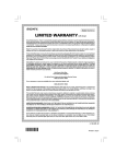
SB Series Brazed Plate Heat Exchanger Installation Manual COLD HOT Exploded view of Schmidt SB Brazed Plate Heat Exchanger. WARNING Before proceeding with installation and operation read entire manual carefully. Failure to do so can cause injury or property damage. Page 2 Table of Contents Product Information.......................................................................4 Description . ..........................................................................4 Thermal Efficiency.................................................................4 Corrosion Free Duty..............................................................4 Low Fouling...........................................................................4 Common Applications ...........................................................4 Technical Data, Dimensions .................................................5 Installation Guide...........................................................................6 Mounting Positions ...............................................................6 Piping Connections . .............................................................7 Typical Piping Configurations................................................8 Soldering and Welding Connections ....................................9 Maintenance.................................................................................. 10 Start-Up and Shut-Down Procedures..................................10 – Start-Up Venting.....................................................10 – Shut Down..............................................................10 Fouling and Cleaning . ........................................................10 Corrosion Resistance .........................................................10 Application Submittal Form......................................................... 11 Page 3 Product Information Description API Schmidt-Bretten SB brazed plate heat exchangers are designed with up to 150 plates - embossed plates of corrosion resistant stainless steel. The plates are brazed together, with every other plate inverted to create contact points between all of the plates. When these points are vacuum brazed together a compact and pressure resistant heat exchanger is formed in which virtually all the material is utilized for heat transfer. Thermal Efficiency The flow pattern produces very high fluid turbulence to increase the effective heat transfer rate. The fluids are in true counter-current flow, resulting in the largest possible temperature difference between the fluids and superior heat transfer rates across the stainless steel plates. Counter-current flow also allows very close approach temperatures between the two circuits. A fluid can be cooled or heated to within just a few degrees of the other fluid. There is no outer shell, as in traditional shell and tube equipment, so virtually the entire heat exchanger is heat transfer surface. This results in extraordinary thermal and economic efficiency. Corrosion Free Duty The plates and nozzles are made of stainless steel, known for very high corrosion resistance. It is the same material used in sanitary, food processing and medical applications. The plates are high vacuum induction brazed with 99.9% pure copper. This produces high strength and very low corrosion potential. Low Fouling The SB brazed plate heat exchanger operates with high fluid turbulence which exhibits a scouring action as it impinges against the heat transfer plates. Turbulence inhibits the production of scale from minerals precipitating out of solution. Common Applications • Steam heating of process liquids • Steam to water heating for district heating and other HVAC applications • Heat recovery, due to the close-approach capability between the fluids • Industrial process cooling or heating of fluids and gases • Refrigerant gas evaporating or condensing • Hydraulic oil cooling (can be designed to use less cooling water) • Lube oil cooling of machinery Page 4 Technical Data, Dimensions API Model Type A B Dimensions C D E SB1 SB2 SB22 SB24 SB3 SB4 SBD4 SB5 SBD5 SB7 SB8 SB9 SB10 SBN1 SBN2 SBN22 SBN24 SBN3 SBN4 SBN5 SBN7 SBE8 SBE9 SBE10 SBE4 SBE5 SBE7 2.87 3.50 3.50 3.50 4.88 4.88 4.88 4.88 4.88 10.59 10.59 10.59 15.08 8.00 9.06 12.80 18.15 6.73 13.07 13.07 20.83 20.83 20.83 20.83 31.42 34.25 B 1.57 1.69 1.69 1.69 2.88 2.88 2.88 2.88 2.88 7.88 6.34 6.34 9.33 Dimensions C 6.69 7.19 10.98 16.34 4.72 11.06 11.06 18.81 18.81 18.11 16.57 27.17 28.46 0.3+0.09N 0.47+0.09N 0.47+0.09N 0.47+0.09N 0.51+0.09N 0.51+0.09N 0.51+0.094N 0.51+0.094N 0.51+0.094N 0.53+0.095N 0.53+0.095N 0.53+0.095N 0.91+0.095N SB1 SB2 SB22 SB24 SB3 SB4 SBD4 SB5 SBD5 SB7 SB8 SB9 SB10 SBN1 SBN2 SBN22 SBN24 SBN3 SBN4 SBN5 SBN7 SBE8 SBE9 SBE10 SBE4 SBE5 SBE7 73 89 89 89 124 124 124 124 124 269 269 269 383 203 230 325 461 171 332 332 529 529 529 529 798 870 40 43 43 43 73 73 73 73 73 200 161 161 237 170 182 279 415 120 281 281 478 478 460 421 690 723 7.0+2.3N 12.0+2.3N 12.0+2.3N 12.0+2.3N 13.0+2.3N 13.0+2.3N 13.0+2.4N 13.0+2.4N 13.0+2.4N 13.5+2.4N 13.5+2.4N 13.5+2.4N 23+2.4N API Model Type A D Page 5 E Max Surface per Number of Plate Plates (sq. ft.) 40 50 100 60 100 110 110 130 130 200 200 300 300 0.15 0.193 0.274 0.366 0.193 0.377 0.377 0.634 0.634 1.453 1.4 2.15 3.23 40 50 100 60 100 110 110 130 130 200 200 300 300 0.014 0.018 0.025 0.034 0.018 0.035 0.035 0.059 0.059 0.135 0.13 0.2 0.3 Max Surface per Number of Plate Plates (sq. m.) Max Flow (gpm) Weight Empty (lbs) 20 50 50 50 75 75 75 75 75 175 282 300 850 1.54+0.11N 2.42+0.13N 3.14+0.18N 4.20+0.31N 2.64+0.13N 3.52+0.29N 3.52+0.37N 4.41+0.53N 4.41+0.59N 21.2+1.2N 22.1+1.2N 25.4+1.8N 87.1+2.8N Max Flow (m3/h) Weight Empty (Kg) 20 50 50 50 75 75 75 75 75 175 282 300 850 0.7+0.05N 1.1+0.06N 1.3+0.08N 2.04+0.14N 1.2+0.06N 1.6+0.13N 1.6+0.17N 2.0+0.24N 2.0+0.27N 9.6+0.54N 10.0+0.54N 11.5+0.8N 39.5+1.25N Installation Guide API Schmidt-Bretten Heat Exchangers should be installed so that there is sufficient space around each unit to perform maintenance. Mounting Positions Heating Applications - The primary side is indicated by a RED label. For heating applications, the heat exchanger can be mounted in any position. However, for any position other than vertical, a loss in performance is possible. Page 6 Refrigeration Applications - The refrigerant side is indicated by a BLUE label. In evaporating and condensing applications, install the heat exchanger in a vertical position to optimize it’s performance. Bracket Mounting and Vibration Isolation It is preferable for the heat exchanger to be supported by a bracket or mounted onto a console. Do not support the unit by the fittings. All items should be supported independently. Transmitted vibrations and pulsations should be minimized by installing a vibration isolator in the fluid lines and by installing a rubber buffer pad between the heat exchanger and its mounting surface. WARNING The heat exchanger may have sharp edges. Exercise caution when handling. Piping Connections Connections to the heat exchanger are identified by a color label. Red Label - primary side in heating systems: hot inlet/outlet Blue Label - primary side in refrigeration applications: refrigerant inlet/outlet Counter-Flow Piping Standard heating connections are NPT threaded. Standard refrigerant connections are ODF solder ports. All connections are on the front side except for two-circuit refrigerant designs where water connections are on the back side. Optional Connections Brazed plate heat exchangers can be supplied with sets of unions, brass unions with external thread or inner solder, steel unions for welding. Page 7 Typical Piping Configurations Heating Application The primary side liquid/gas enters at the top of the left side as indicated by the red label and exits at the bottom. To acheive optimum performance, pipe the secondary circuit in counter-flow with the liquid entering at the bottom and leaving at the top of the heat exchanger. Series Connections Thermal length is a term that refers to the addition of heat transfer surface while preserving the internal fluid velocity to maximize the effective heat transfer rate. Page 8 Refrigerant Condenser The refrigerant gas enters at the top and the condensate (liquid) exits at the bottom. To acheive optimum performance, pipe the water circuit in counter-flow with the water entering at the bottom and leaving at the top of the heat exchanger. Refrigerant Evaporator The refrigerant liquid/gas mixture enters at the bottom on the left side as indicated by the blue label and exits at the top as a vapor. Soldering and Welding Connections Soldering The temperature of the brazing or welding process must not exceed the melting point of the internal brazing material. Use a wet towel around the connection and the plate pack to reduce the amount of heat transmitted to the pack during installation. 1. Clean the soldering assembly surface at the copper tube and heat exchanger connections. • Remove oil or other buildup with a degreasing agent. • Polish the surfaces to remove oxide. 2. Apply the flux to the surface with a brush to remove and prevent oxidation. 3. For refrigerant applications, use dry nitrogen gas on the refrigerant side. 4. Heat the soldering area to the soldering temperature, about 1,200°F. Temperatures above this can melt the SB brazing materials and result in damage. 5. Keep the tube in a fixed position and apply the filler material. Welding 1. Prepare the edge of the tube for welding with a 30° angle. 2. Place the piping into the connection. 3. TIG or MIG weld the tube into the connection, filling the groove formed by the two edges. This method minimizes the heat zone. Page 9 Maintenance Start-Up and Shut-Down Procedures • S tart-Up Venting - During the filling process, the unit must be vented to eliminate any trapped air. This will assure proper performance and longevity of the unit. • S hut Down - The two sides should be shut down slowly and simultaneously. If this is not possible the hot side should be shut down first. If the unit is shut down for an extended period of time, it must be drained and cleaned. This is especially true if there is a risk of frost or if there is the presence of any aggressive media inside the heat exchanger. Fouling and Cleaning Different factors may effect fouling such as fluid velocity, turbulence, flow distribution, surface finish and water quality. Proper maintenance and adequate water treatment can help reduce fouling. Properly sized strainers should be installed where particles are known to exist. Strainers with a mesh size of 16-20 will retain any particles over 0.04” in size. In installations where high calcium hardness or fluid contamination is expected, the heat exchanger should be cleaned periodically by flushing, back-flushing and cleaning the strainers. Following are descriptions for two types of fouling: Scaling Deposits of calcium on the heat transfer surface. This effect increases with temperatures higher than 140°F, concentration, and pH level. Assuring a turbulent flow and lower temperature can help reduce this effect. Particulate Solids in suspension in the heat transfer media. Particulate fouling can be influenced by velocity and media flow, roughness of the surface and physical size of the particles. Corrosion Resistance Corrosion is a complex process influenced by a number of factors. The chart and table below show the resistance of AISI 316 Stainless Steel and Copper against the most common chemicals: Iron < 1.5 ppm Ammonia < 2ppm Sulphide < 0 ppm Free Carbon Acid < 20 ppm Sulfate < 50 ppm pH-Value - 6 - 9 Page 10 Mangan < .05 ppm Nitrate < 100 ppm Chlorides - See Below Application Submittal Form Job: Date: Engineer: Submitted By: Contractor: Approved By: Product Description API Schmidt-Bretten brazed plate heat exchangers consist of as many as 150 pattern embossed stainless steel plates. The plates are brazed together with every other plate turned 180° to create flow channels with two mediums in counter-current direction. The design of the plates creates a high fluid turbulence resulting in outstanding heat transfer rates. The result is a highly efficient heat exchanger that utilizes all of the material in the heat transfer process. Materials of Construction Plates .................................................... AISI316L Stainless Steel Brazing Materials ................................. Copper (99.9% pure) or Nickel (optional) Connections ......................................... Stainless Steel Operating Conditions Max Working Pressure ........................ 450 psi for Copper, 380 psi for Nickel Max Working Temperature .................. 365°F Minimum Working Temperature .......... -148°F PRODUCT SELECTION DATA Side One Side Two Medium (Water, Glycol, Oil, etc.) ________ ________ Concentration (Percent) ________ ________ State of Fluid (Vapor or Liquid) (Degrees F) ________ ________ Inlet Temp (Degrees F) ________ ________ Outlet Temp (Degrees F) ________ ________ Mass Flow Rate (gpm) ________ ________ Max Pressure Drop (psi) ________ ________ Total Heat Transfer (BTUH) ________ ________ Page 11 Other Products Available from API Heat Transfer API Heat Transfer Inc. 2777 Walden Avenue Buffalo, New York 14225 (716) 684-6700 www.apiheattransfer.com Divisions: API Airtech ISO-9001 Certified Air Cooled Aluminum Heat Exchangers Brazed Plate Heat Exchangers SIGMAWIG Welded Plate Heat Exchangers Off-the-shelf, standard units reflects the latest in plate heat exchanger technology for maximum performance and low cost. Ideal for OEM or aftermarket applications. Many Models stocked and ready to ship. Models for process or refrigeration applications. Fully welded and require no gaskets. Available in all 316SS construction, titanium and other higher alloy materials. These units have a design temperature of 750°F and can handle operating pressures as high as 360 psi with an ASME Code stamp. Hubbed Shell and Tube Heat Exchangers SIGMASTAR® Evaporator Systems Straight or U-tube, fixed or removable tubesheet general purpose exchangers designed to cool oil, water, compressed air and other industrial fluids. A variety of port configurations and materials are available. Diameters from 3’’ (7.62 cm) to 12’’ (30.48 cm). Utilizing the SIGMASTAR® plate, this evaporator system is designed to remove water or other solvents, while concentrating solutions. SIGMASTAR® Systems can be pre-assembled and pre-tested prior to shipment for quick and easy start up. OptiDesign® TEMA Shell and Tube Straight-tube, removable bundle exchangers made from standard components. Floating tube sheet for seal leak detection and easy maintenance. Diameters from 3” (7.62 cm) to 42” (106.68 cm). ASME, API, TEMA, ABS and other codes available. A wide variety of TEMA types are available using pre-engineered or custom designs in various sizes and materials. Shell diameters from 6’’ (15.24 cm) to 60’’ (152.4 cm), ASME, TEMA, API, ABS, TUV, PED and other code constructions available. Extended Surface Air-Cooled Heat Exchangers Unique, patented plate-fin design for centrifugal or axial compressor intercooler and aftercooler applications and minimal pressure loss. Design eliminates separators. ASME code design is standard. Diameters from 20” (50.8 cm) to 120” (304.8 cm). High efficiency, brazed aluminum coolers for cooling a wide variety of liquids and gases with ambient air. Lightweight, yet rugged. Capable of cooling multiple fluids in single unit. Models can be supplied with cooling fan and a variety of drives. 91 North Street • P.O. Box 68 Arcade, New York 14009-0068 (585) 496-5755 • Fax: (585) 496-5776 API Basco ISO-9001 Certified Basco®/Whitlock® Shell & Tube Heat Exchangers 2777 Walden Avenue Buffalo, New York 14225 (716) 684-6700 • Fax: (716) 684-2129 API Schmidt-Bretten Americas Plate Heat Exchangers and Thermal Systems 2777 Walden Avenue Buffalo, New York 14225 (716) 684-6700 • Fax: (716) 684-2129 API Schmidt-Bretten GmbH & Co. KG ISO-9001 Certified Plate Heat Exchangers and Thermal Systems Langenmorgen 4 D-75015 Bretten, Germany (49)725253-0 • Fax: (49)725253-200 API Heat Transfer (Suzhou) Co., Ltd. Air Cooled Aluminum Heat Exchangers Shell & Tube Heat Exchangers Plate Heat Exchangers 156 Qingqiu Street, 3rd District Suzhou Industrial Park Suzhou, Jiangsu 215126 China (86)512-88168000 • Fax: (86)512-88168003 Contact your local API Sales Representative or API Heat Transfer directly toll-free: 1-877-API-HEAT e-mail: [email protected] Form SBCBE 8/07 © 2007 API Heat Transfer Printed in USA