1
RFID System
V680 Series
User's Manual
ID Controller
V680-CA5D01-V2
V680-CA5D02-V2
Man. No. Z249-E1-11
Introduction
Thank you for purchasing a V680/V680S-series RFID System. This manual describes the functions, performance, and application methods needed for optimum use of the V680/V680S-series RFID System.
Please observe the following items when using the RFID System.
• Allow the RFID System to be installed and operated only by qualified specialist with a sufficient
knowledge of electrical systems.
• Read and understand this manual before attempting to use the RFID System and use the RFID System correctly.
• Keep this manual in a safe and accessible location so that it is available for reference when required.
READ AND UNDERSTAND THIS DOCUMENT
SECTION 1 Product Overview
SECTION 2 Installation, Connections, and Wiring
SECTION 3 Preparations for Communications
SECTION 4 Functions
SECTION 5 Communications
SECTION 6 Troubleshooting
SECTION 7 Appendices
RFID System
V680-CA5D01-V2
V680-CA5D02-V2
User’s Manual
ID Controller
ID Controller
Introduction SECTION 1 SECTION 2 SECTION 3 SECTION 4 SECTION 5 SECTION 6 SECTION 7
Introduction
Introduction
Introduction
READ AND UNDERSTAND THIS DOCUMENT
Please read and understand this document before using the products. Please consult your OMRON representative if you have any questions or comments.
WARRANTY
OMRON’s exclusive warranty is that the products are free from defects in materials and workmanship for a period of one year (or other period if specified)
from date of sale by OMRON.
OMRON MAKES NO WARRANTY OR REPRESENTATION, EXPRESS OR IMPLIED, REGARDING NON-INFRINGEMENT, MERCHANTABILITY, OR FITNESS FOR PARTICULAR PURPOSE OF THE PRODUCTS. ANY BUYER OR USER ACKNOWLEDGES THAT THE BUYER OR USER ALONE HAS
DETERMINED THAT THE PRODUCTS WILL SUITABLY MEET THE REQUIREMENTS OF THEIR INTENDED USE. OMRON DISCLAIMS ALL OTHER
WARRANTIES, EXPRESS OR IMPLIED.
LIMITATIONS OF LIABILITY
OMRON SHALL NOT BE RESPONSIBLE FOR SPECIAL, INDIRECT, OR CONSEQUENTIAL DAMAGES, LOSS OF PROFITS OR COMMERCIAL LOSS IN
ANY WAY CONNECTED WITH THE PRODUCTS, WHETHER SUCH CLAIM IS BASED ON CONTRACT, WARRANTY, NEGLIGENCE, OR STRICT LIABILITY.
In no event shall responsibility of OMRON for any act exceed the individual price of the product on which liability is asserted.
IN NO EVENT SHALL OMRON BE RESPONSIBLE FOR WARRANTY, REPAIR, OR OTHER CLAIMS REGARDING THE PRODUCTS UNLESS OMRON’S
ANALYSIS CONFIRMS THAT THE PRODUCTS WERE PROPERLY HANDLED, STORED, INSTALLED, AND MAINTAINED AND NOT SUBJECT TO CONTAMINATION, ABUSE, MISUSE, OR INAPPROPRIATE MODIFICATION OR REPAIR.
SUITABILITY FOR USE
THE PRODUCTS CONTAINED IN THIS DOCUMENT ARE NOT SAFETY RATED. THEY ARE NOT DESIGNED OR RATED FOR ENSURING SAFETY OF
PERSONS, AND SHOULD NOT BE RELIED UPON AS A SAFETY COMPONENT OR PROTECTIVE DEVICE FOR SUCH PURPOSES. Please refer to separate catalogs for OMRON's safety rated products.
OMRON shall not be responsible for conformity with any standards, codes, or regulations that apply to the combination of products in the customer’s application or use of the product.
At the customer’s request, OMRON will provide applicable third party certification documents identifying ratings and limitations of use that apply to the products. This information by itself is not sufficient for a complete determination of the suitability of the products in combination with the end product, machine,
system, or other application or use.
The following are some examples of applications for which particular attention must be given. This is not intended to be an exhaustive list of all possible uses
of the products, nor is it intended to imply that the uses listed may be suitable for the products:
• Outdoor use, uses involving potential chemical contamination or electrical interference, or conditions or uses not described in this document.
• Nuclear energy control systems, combustion systems, railroad systems, aviation systems, medical equipment, amusement machines, vehicles, safety
equipment, and installations subject to separate industry or government regulations.
• Systems, machines, and equipment that could present a risk to life or property.
Please know and observe all prohibitions of use applicable to the products.
NEVER USE THE PRODUCTS FOR AN APPLICATION INVOLVING SERIOUS RISK TO LIFE OR PROPERTY WITHOUT ENSURING THAT THE SYSTEM
AS A WHOLE HAS BEEN DESIGNED TO ADDRESS THE RISKS, AND THAT THE OMRON PRODUCT IS PROPERLY RATED AND INSTALLED FOR THE
INTENDED USE WITHIN THE OVERALL EQUIPMENT OR SYSTEM.
PERFORMANCE DATA
Performance data given in this document is provided as a guide for the user in determining suitability and does not constitute a warranty. It may represent the
result of OMRON’s test conditions, and the users must correlate it to actual application requirements. Actual performance is subject to the OMRON Warranty
and Limitations of Liability.
CHANGE IN SPECIFICATIONS
Product specifications and accessories may be changed at any time based on improvements and other reasons.
It is our practice to change model numbers when published ratings or features are changed, or when significant construction changes are made. However,
some specifications of the product may be changed without any notice. When in doubt, special model numbers may be assigned to fix or establish key specifications for your application on your request. Please consult with your OMRON representative at any time to confirm actual specifications of purchased products.
DIMENSIONS AND WEIGHTS
Dimensions and weights are nominal and are not to be used for manufacturing purposes, even when tolerances are shown.
ERRORS AND OMISSIONS
The information in this document has been carefully checked and is believed to be accurate; however, no responsibility is assumed for clerical, typographical,
or proofreading errors, or omissions.
PROGRAMMABLE PRODUCTS
OMRON shall not be responsible for the user’s programming of a programmable product, or any consequence thereof.
COPYRIGHT AND COPY PERMISSION
This document shall not be copied for sales or promotions without permission. This document is protected by copyright and is intended solely for use in conjunction with the product. Please notify us before copying or reproducing this document in any manner, for any other purpose. If copying or transmitting this
document to another, please copy or transmit it in its entirety.
2
RFID System
User's Manual
Introduction
Introduction
Safety Precautions
● Alert Symbols for Safe Use
The following symbols are used in this manual to indicate precautions that must be observed to ensure safe
use of the V680-CA5D@@-V2. The precautions provided here contain important safety information. Be sure to
observe these precautions.
The following signal words are used in this manual.
Indicates a potentially hazardous situation which, if not avoided, will result in minor or
WARNING moderate injury, or may result in serious injury or death. Additionally, there may be
significant property damage.
● Meanings of Alert Symbols
Indicates general prohibitions for which there is no specific symbol.
● Warning
WARNING
This Product is not designed to be used either directly or indirectly in applications that detect
human presence for the purpose of maintaining safety. Do not use this Product as a sensing
device for protecting human lives.
Precautions for Safe Use
Be sure to observe the following precautions to ensure safe use of the Product.
1. Do not use the Product in environments with flammable, explosive, or corrosive gases.
2. Do not attempt to disassemble, repair, or modify the Product.
3. Tighten the base mounting screws and terminal block screws securely.
4. Be sure to use crimp terminals of the specified size for wiring.
5. If any cable has a locking mechanism, make sure that it has been locked before using the cable.
6. Make sure the power supplied by the DC power supply unit is within the rated power supply voltage (24
VDC +10%/15%) before using the Product.
7. Do not connect the power supply in reverse.
8. Do not allow water or wires to enter the Product through gaps in the case. Otherwise, fire or electric shock
may occur.
9. Turn OFF the power to the Controller before attaching or removing an Amplifier or Antenna.
10.If an error is detected in the Product, immediately stop operation and turn OFF the power supply.
Consult with an OMRON representative.
11.Dispose of the Product as industrial waste.
12.Observe all warnings and precautions given in the body of this manual.
RFID System
User's Manual
3
Introduction
Introduction
Precautions for Correct Use
Always observe the following precautions to prevent operation failure, malfunctions, and adverse effects on
performance and equipment.
1. Installation Environment
Do not use the Product in the following locations.
• Locations exposed to corrosive gases, dust, metallic powder, or salts
• Locations not within the specified operating temperature range
• Locations subject to rapid changes in temperature or condensation
• Locations not within the specified operating humidity range
• Locations subject to direct vibration or shock outside the specified ranges
• Locations subject to spray of water, oil, or chemicals
2. Installation
• This Product uses a frequency band of 13.56 MHz to communicate with RF Tags. Some transceivers,
motors, inverters, switching power supplies, etc., generate electrical noise that will affect these communications. If any of these devices are located in the vicinity of the Product, they may affect communications with RF Tags, and may possibly damage the RF Tags. Prior to using the Product in the
vicinity of any of these devices, perform a test to determine whether the Product can be used under
the resulting influence.
• Observe the following precautions to minimize the effects of normal noise.
(1) Ground the ground terminal on the Product and all metal objects in the vicinity of the Product to
100 or less.
(2) Do not use the Product near high-voltage or high-current lines.
• The Product is not waterproof. Do not use it in an environment where mist is present.
• Do not expose the Product to chemicals that adversely affect the Product materials.
• Use a tightening torque of 1.2 N·m max.
• If multiple Antennas are mounted near each other, communications performance may decrease due
to mutual interference. Refer to Installing Antennas in the V680 Series User's Manual for Amplifiers,
Antennas, and RF Tags (Cat. No. Z262, Z248) and check to make sure there is no mutual
interference.
3. Storage
Do not store the Product in the following locations.
• Locations exposed to corrosive gases, dust, metallic powder, or salts
• Locations not within the specified operating temperature range
• Locations subject to rapid changes in temperature or condensation
• Locations not within the specified storage humidity range
• Locations subject to direct vibration or shock outside the specified ranges
• Locations subject to spray of water, oil, or chemicals
4. Cleaning
• Using thinner, benzene, acetone, or kerosene for cleaning may affect the resin parts and the surface
of the case. For detail, refer Chemical Resistance of RF Tags in the V680 Series User's Manual for
Amplifiers, Antennas, and RF Tags (Cat. No. Z262, Z248) and do not use chemicals that affect the
resin parts and the surface of the case.
4
RFID System
User's Manual
Introduction
Communicate with the host device only after confirming that the CIDRW Controller has started. Also,
unstable signals may occur at the host interface when the CIDRW Controller is started. When initializ-
Introduction
5. Communications with the Host Device
ing operation, clear the reception buffer at the host device or take other suitable methods to clear
unwanted signals.
6. Startup Precaution
Never turn OFF the power supply while the CIDRW Controller is starting, including when power is
turned ON, when the mode is changed, or when the CIDRW Controller is being reset. Doing so may
damage the CIDRW Controller.
RFID System
User's Manual
5
Introduction
Introduction Meanings of Symbols
Meanings of Symbols
Indicates particularly important points related to a function, including precautions and application
advice.
Indicates page numbers containing relevant information.
Indicates reference to helpful information and explanations for difficult terminology.
6
RFID System
User's Manual
Introduction
Introduction
Table of Contents
Introduction
Safety Precautions
3
Precautions for Safe Use
3
Precautions for Correct Use
4
Meanings of Symbols
6
Table of Contents
7
SECTION 1 Product Overview
9
Features
10
Using Heat-resistive RF Tags (V680-D1KP58HTN or V680-D1KP58HT)
13
Using V680S-D8KF@@ RF Tags
14
Part Names and Functions
15
System Configuration
21
Application Flowchart
27
SECTION 2 Installation, Connections, and Wiring
29
Installation
30
Connection and Wiring
32
SECTION 3 Preparations for Communications
63
Switch Settings
64
RF Tag Memory Setting
82
Trial Operation
88
SECTION 4 Functions
91
Trigger Input
92
Write Protection
93
RF Tag Service Life Check
103
RF Tag Memory Check
105
RF Tag Memory Error Correction
106
Write Command Memory
107
RFID System
User’s Manual
7
Introduction
Introduction
Noise Monitor Function
SECTION 5 Communications
109
RF Tag Operation and Command Status
110
V600-V680 Command Correspondence
113
V680 Commands
115
V600 Commands
181
SECTION 6 Troubleshooting
247
Self-diagnostic Function
248
Error Lists
249
Errors and Countermeasures
253
Maintenance and Inspection
254
Troubleshooting
255
SECTION 7 Appendices
8
108
261
Specifications and Dimensions
262
Characteristics According to Operating Conditions
266
RF Tag Memory Map
275
RF Tag Memory Capacity and Memory Type
277
ASCII Table
278
Degree of Protection
279
Upgrade information
281
Revision History
282
RFID System
User’s Manual
SECTION 1
SECTION 1
Product Overview
10
Using Heat-resistive RF
Tags (V680-D1KP58HTN or V680-D1KP58HT)
13
Using V680S-D8KF @@ RF Tags
14
Part Names and Functions
15
System Configuration
21
Application Flowchart
27
RFID System
User’s Manual
Product Overview
Features
9
SECTION 1
Product Overview
Features
The V680-CA5D@@-V2 ID Controllers connect to V680-HA63 Amplifiers and V680-HS@@ Antennas, or to
SECTION 1 Features
10
V680-H01 or V680-H01-V2 Antennas, to read and write data for V680-series RF Tags according to
commands from the host device. The ID Controller returns the results of executing these commands as
responses to the host device.
The ID Controller can communicate with RF Tags that conform to ISO 18000-3 (ISO 15693). The ID Controller may not be able
to communicate with RF Tags that are not V680-series RF Tags. Always confirm that communications are possible in advance.
RFID System
User’s Manual
SECTION 1
Product Overview
Differences between the V680-CA5D@@ and V680-CA5D@@-V2
The following functions have been added to the V680-CA5D@@-V2 in addition to those found on the
CA5D@@ can be directly replaced by the V680-CA5D@@-V2.
New Commands Added
The following commands have been added.
READ TAG MEMORY
ERROR CORRECTION
QR
Reads the RF Tag's memory contents. Also uses a memory check code to
inspect data reliability.
WRITE TAG MEMORY
ERROR CORRECTION
QW
Writes data to the memory of the RF Tag. Also writes the memory check code for
the data reliability inspection to the memory of the RF Tag.
READ ID
ID
Reads the RF Tag's ID code.
UID ADDITION SET
US
Sets whether or not UID should be added to the read command (RD) response.
SECTION 1 Features
V680-CA5D@@. These functions are upward-compatible with the V680-CA5D@@, so the V680-
Communications Designations Added
Multi-access, FIFO, and selective have been added to the communications designations.
Note: These designations cannot be used for communications with the V680-D1KP@@.
Connect V680-H01 or V680-H01-V2 Antennas
A DIP switch setting (SW4 pin 8) can be changed to enable using V680-H01 or V680-H01-V2 Antennas.
The V680-H01 and V680-H01-V2 Antennas can be connected only to the V680-CA5D01-V2 ID Controller.
They cannot be connected to the V680-CA5D02-V2 ID Controller.
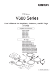
High-speed Data Transmission Supported
High-speed data transmission is possible by setting DIP SW4, pin 10.
The V680-H01 and V680-H01-V2 Antennas do not support the high-speed mode for data communications.
DIP SW4
1
2
3
4
5
6
7
8
9
0
V680-H01 Antenna connection setting (DIP SW4, pin 8)
High-speed Data Transmission setting (DIP SW4, pin 10)
RFID System
User’s Manual
11
SECTION 1
Product Overview
Differences between Version 2.0 and Version 2.1
The following functions have been added to version 2.1 in addition to those found on version 2.0.
These functions are upward-compatible with version 2.0, so version 2.0 can be directly replaced with
SECTION 1 Features
version 2.1.
Parameter Added to V600 PARAMETER SET (SP) Command
A parameter for the write protection method has been added to the PARAMETER SET (SP) command
of the V600 commands.
Write Protect Method Added
By setting the write protection method with the PARAMETER SET (SP) command of the V600 commands, you can use both the V600 EEPROM-type write protection method and the V600 SRAM-type
write protection method.
Differences between Version 2.1 and 2.3
The following functions have been added to version 2.3 in comparison to version 2.1. Functions are
upwardly compatible, so version 2.1 can be replaced with version 2.3.
CA1D Mode Added for RF Tag Memory Setting
If you are using a V680-CA1D/-CA2D ID Controller, always set the RF Tag memory setting to CA1D
Mode. Setting the RF Tag memory setting to CA1D Mode enables reading and writing Heat-resistant
RF Tags (V680-D1KP58HTN and V680-D1KP58HT) that were written by the V680-CA1D/-CA2D.
Parameter Added to PARAMETER SET (SP) Command
A parameter to set the RF Tag memory setting was added to PARAMETER SET (SP) command.
The RF Tag memory setting is made in the ID Controller. A different memory map may be used when reading or writing
Heat-resistant RF Tags (V680-D1KP58HTN and V680-D1KP58HT) that were written by the V680-CA1D/-CA2D I/O
Controller from a Reader/Writer that is manufactured by a company other than OMRON.
Refer to RF Tag Memory Setting under Section 3 Preparations for Communications
p. 82
12
RFID System
User’s Manual
SECTION 1
Product Overview
This section provides information for using Heat-resistive RF Tags (V680-D1KP58HTN or V680-D1KP58HT).
If you are not using a Heat-resistive RF Tag, set the RF Tag memory setting to Standard Mode.
Precautions for Saving Data at High Temperatures
If you are using Heat-resistive RF Tags (V680-D1KP58HTN or V680-D1KP58HT), write the data again
after saving data at a high temperature even if it is not necessary to change the data. A “high temperature” is one between 110C and 200C.
Using the V680-CA1D/-CA2D
If you are using Heat-resistive RF Tags (V680-D1KP58HTN or V680-D1KP58HT) and also using a
V680-CA1D/-CA2D ID Controller, set the RF Tag memory setting of the V680-CA5D01-V2 (version 2.3
or newer) to CA1D Mode.
If you are not using the V680-CA1D/-CA2D ID Controller, the RF Tag memory setting does not need to be changed.
Refer to information in Part Names and Functions.
Combining the V680-CA1D/-CA2D with Other Models
When using other models of ID Controller with the V680-CA1D/-CA2D, make sure that the version
allows setting the RF Tag memory setting to CA1D Mode.
SECTION 1 Using Heat-resistive RF Tags (V680-D1KP58HTN or V680-D1KP58HT)
Using Heat-resistive RF Tags (V680-D1KP58HTN or
V680-D1KP58HT)
Product versions are displayed on the monitor display when the power supply is turned ON.
To use the V680-CA5D01-V2, it must be version 2.3 or newer.
To use the V680-CH@D, it must be version 1.1 or newer.
To use the CS/CJ1W-V680C1@, it must be version 1.2 or newer.
RFID System
User’s Manual
13
SECTION 1
Product Overview
Using V680S-D8KF@@ RF Tags
To use the V680-CA5D0@-V2, it must be version 2.5 or newer. (Production after October 2014)
SECTION 1 Using V680S-D8KF @@ RF Tags
14
RFID System
User’s Manual
SECTION 1
Product Overview
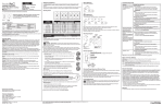
Part Names and Functions
SECTION 1 Part Names and Functions
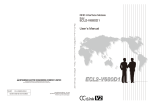
Part Names
V680-CA5D01-V2
Controller Number Switches
Main Indicators
Switch Cover
USB Port
Monitor display
Bar Indicator
RS-422/RS-485 Port
Mode Switch
Antenna Port
Terminating Resistance Switch
Power Supply Terminals
Antenna Operation Indicators
External I/O Port
Ground Terminal
RS-232C Port
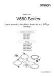
V680-CA5D02-V2
Controller Number Switches Main Indicators
Switch Cover
USB Port
Monitor display
Bar Indicator
RS-422/RS-485 Port
Mode Switch
Terminating Resistance Switch
Antenna Port
Power Supply Terminals
Antenna Operation
Indicators
External I/O Port
Ground Terminal
RS-232C Port
RFID System
User’s Manual
15
SECTION 1
Product Overview
Power Supply and Ground Terminals
Description
Description
SECTION 1 Part Names and Functions
Power supply terminals
Supply 24 VDC power to these terminals.
Recommended power supply: OMRON S8VS-03024.
Ground terminal
The ground terminal. Connect this terminal to an independent ground line connected to 100 . or
less.
External I/O Port
The external I/O port is used to connect external I/O signals.
There are two external I/O signal arrangements that can be used for the same port: the same signal
arrangement as the V600-CA5D@@ and a signal arrangement unique to the V680-CA5D@@-V2.
The desired I/O signal arrangement can be specified using the PARAMETER SET (SP) command. In
Self-execution Mode, the use of ports other than RUN and RST can be set.
Description
V600 I/O
RUN
16
Description
V680 I/O
Turns ON when the ID Controller is operating normally and the communications are possible with the
host device.
BUSY
OUT3
BUSY: Output from when a RF Tag communications command is received from the host device until
RF Tag communications have been completed. This is the default setting.
OUT3: User output 3. This output can be controlled with the CONTROLLER CONTROL (CC) command.
ERROR
OUT4
ERROR: Output for 500 ms when a RF Tag communications error, host communications error, or
hardware error has occurred. The output time can be changed with the PARAMETER SET
(SP) command. This is the default setting.
OUT4: User output 4. This output can be controlled with the CONTROLLER CONTROL (CC) command.
OUT1
OUT1: User output 1. This output can be controlled with the CONTROLLER CONTROL (CC) command.
OUT2
OUT2: User output 2. This output can be controlled with the CONTROLLER CONTROL (CC) command.
COM_O
Common terminal for outputs.
RST
External reset input for emergency stops. The ID Controller is reset when an input is received.
TRG1
V680 Command System
If a trigger communications designation (SI, RI, or PI) is specified, the command received by Antenna
1 will be executed on the rising edge of the TRG1 input. If any other communications designation is
specified, TRG1 is used as user input 1, which can be read using the CONTROLLER CONTROL
(CC) command.
V600 Command System
If pin 6 on DIP switch SW4 (Lower Trigger Execution Setting) is turned ON, any command already
received by Antenna 1 will be executed on the rising edge of the TRG1 Input. If pin 6 is turned OFF,
TRG1 is used as user input 1, which can be read using the CONTROLLER CONTROL (CC) command.
TRG2
V680 Command System
If a trigger communications designation (SI, RI, or PI) is specified, the command received by Antenna
2 will be executed on the rising edge of the TRG2 input. If any other communications designation is
specified, TRG2 is used as user input 2, which can be read using the CONTROLLER CONTROL
(CC) command.
V600 Command System
If pin 6 on DIP switch SW4 (Lower Trigger Execution Setting) is turned ON, any command already
received by Antenna 2 will be executed on the rising edge of the TRG2 input. If pin 6 is turned OFF,
TRG2 is used as user input 2, which can be read using the CONTROLLER CONTROL (CC) command.
COM_I
Common terminal for inputs
RFID System
User’s Manual
SECTION 1
Product Overview
RS-232C Port
The RS-232C port is used to communicate with a host device. A computer, PLC, or similar host device
RS-422/RS-485 Port
The RS-422/RS-485 port is used to communicate with a host device. Computers, PLCs, and similar
host devices with RS-422/RS-485 interfaces can be connected.
USB Port
The USB port is used to connect to a computer via a USB cable. The port is USB 1.1.
Communications with host devices using USB connections can be made using only 1:1 protocol,
regardless of the setting of pin 9 on DIP switch SW3.
The USB port is not a control port. Always use the RS-232C port or RS-422/RS-485 port when building systems.
p. 21
SECTION 1 Part Names and Functions
with an RS-232C interface can be connected.
Antenna Port
The antenna port is used to connect V680-series Amplifiers and Antennas.
Controller Number Switches
The Controller number switches are used to set the number of the ID Controller when connecting more
than one ID Controller to one host device.
Refer to Controller Number Switch Settings (SW1, SW2) for details on this switch.
p. 66
Switch Cover
There are two DIP switches behind the switch cover for making settings.
Refer to DIP Switch Settings (SW3, SW4) for details on these switches.
p. 67
Mode Switch
The mode switch is used to change the ID Controller's operation mode (between Run and
Maintenance Mode).
Refer to Mode Switch Setting for details on this switch.
p. 70
Terminating Resistance Switch
This switch can be use to connect or disconnect the internal terminating resistance.
Refer to Terminating Resistance for details on this switch.
p. 70
RFID System
User’s Manual
17
SECTION 1
Product Overview
Main Indicators
Indicator
Color
SECTION 1 Part Names and Functions
RUN/RST
Green
COMM
Green
Description
Lit while the ID Controller is operating normally.
Red
Lit while external reset signal is being input.
Lit during normal communications with a host device.
Red
Lit when an error is detected for communications with a host device.
Antenna Operation Indicators
Indicator
Color
Description
COMM1
Yellow
Lit during processing of commands for RF Tag communications by Antenna 1.
NORM1/
ERR1
Green
Lights once upon normal completion of processing by Antenna 1.
COMM2
(See note.)
NORM2/
ERR2
(See note.)
Red
Lights once when processing ends in an error at Antenna 1.
Lit during processing of commands for communications with RF Tags by Antenna 2.
Yellow
Green
Lights once upon normal completion of processing by Antenna 2.
Lights once when processing ends in an error at Antenna 2.
Red
Note: The V680-CA5D01-V2 does not have COMM2 or NORM2/ERR2 indicators.
Monitor Display
Indicator
7-segment
display
(2 digits)
Color
Red
Mode
Run Mode
RFID System
User’s Manual
Description
Displays end codes.
Self-execution Mode
Maintenance
Mode
18
Command Execution
Mode
Distance Level Measure- Converts and measures the Antenna output at six levels.
ment Mode
The level is displayed as either “EE” or 01 to 06.
“--” will be displayed if there is no RF Tag in the Antenna’s
interrogation zone.
RF Tag Communications
Test Mode
Communicates with RF Tags and displays end codes.
p. 157
Speed Level Measurement Mode (read/write)
Repeatedly communicates with moving RF Tags and displays the number of successful communications between
01 and 99. The display will show 99 even if more than 99
successful communications were made.
“EE” will be displayed if the first communication after the
RF Tag entered the interrogation zone fails.
Noise Level Measurement Mode
Displays the ambient noise level between 00 and 99.
Communications Success Rate Measurement
Mode
Communicates 100 times with a RF Tag with no retries,
and displays the communications success rate between 01
and 99 (%). If no communications were successful, “EE” is
displayed. If all communications were successful, “FF” is
displayed.
SECTION 1
Product Overview
Run Mode (SW5 OFF)
In Run Mode, the end codes for command processing is displayed. The end code is displayed in 2-digit
hexadecimal, as shown below.
Hexadecimal
0
1
2
3
4
5
6
7
8
9
A
B
C
D
E
F
Display
SECTION 1 Part Names and Functions
The display is lit for normal and warning responses and flashes for error responses.
The error code “15” will be displayed if the operation conditions have not been set and operation is switched to
Self-execution Mode.
Maintenance Mode (SW5 ON)
In Maintenance Mode, the measurement results for each measurement mode is displayed in 2-digit
decimal.
Checking the Version
The version can be checked on the monitor display when turning ON the power.
Checking Method (example shows version 2.4)
1. Turn ON the power for the V680-CA5D0@-V2.
2. The following appears on the monitor display.
RFID System
User’s Manual
19
SECTION 1
Product Overview
Bar Indicator
Color
1
Yellow
The Antenna and the RF Tag are far apart.
The RF Tag travel speed is fast.
2
Yellow
3
Yellow
4
Yellow
5
Yellow
6
Yellow
The Antenna and RF Tag are close.
The RF Tag travel speed is slow.
SECTION 1 Part Names and Functions
Indicator
Description
Bar Indicator
1
20
RFID System
User’s Manual
6
SECTION 1
Product Overview
System Configuration
SECTION 1 System Configuration
1:1 Connection
One host device is connected via the RS-232C, RS-422, or RS-485 interface.
• Using Antennas Other Than the V680-H01 or V680-H01-V2 Antenna
Personal computer
Programmable Controller
(PLC)
RS-232C, RS-422, or
RS-485 interface
ID Controller
V680-CA5D01-V2
V680-CA5D02-V2
Amplifiers
V680-HA63 A/B
Antennas
V680-HS52
V680-HS63
V680-HS65
V680-HS51
RF Tag
Pallet or other object
RFID System
User’s Manual
21
SECTION 1
Product Overview
• Using a V680-H01 or V680-H01-V2 Antenna
SECTION 1 System Configuration
Programmable Controller
(PLC)
Personal computer
RS-232C, RS-422, or
RS-485 interface
ID Controller
V680-CA5D01-V2
Antennas
V680-H01
V680-H01-V2
RF Tag
Pallet or other object
The V680-H01 or V680-H01-V2 Antenna can be connected only to the V680-CA5D01-V2 ID Controller. It cannot be
used with the V680-CA5D02-V2 ID Controller
22
RFID System
User’s Manual
SECTION 1
Product Overview
1:N Connections with RS-232C Connection to Host Device
The host device can be connected via RS-232C and then other ID Controllers can be connected via
SECTION 1 System Configuration
RS-422/RS-485 interfaces.
• Using Antennas Other Than the V680-H01 or V680-H01-V2 Antenna
Programmable Controller
(PLC)
Personal computer
RS-232C
RS-422/RS-485
RS-422/RS-485
RS-422/RS-485
ID Controller
V680-CA5D01-V2
V680-CA5D02-V2
Amplifiers
V680-HA63 A/B
Antennas
V680-HS52
V680-HS63
V680-HS65
V680-HS51
RF Tag
Pallet or other object
RF Tag
Pallet or other object
RFID System
User’s Manual
23
SECTION 1
Product Overview
• Using a V680-H01 or V680-H01-V2 Antenna
SECTION 1 System Configuration
Programmable Controller
(PLC)
Personal computer
RS-232C
RS-422/RS-485
RS-422/RS-485
RS-422/RS-485
ID Controller
V680-CA5D01-V2
Antennas
V680-H01
V680-H01-V2
RF Tag
Pallet or other object
RF Tag
Pallet or other object
The V680-H01 or V680-H01-H01-V2 Antenna can be connected only to the V680-CA5D01-V2 ID Controller. It cannot
be used with the V680-CA5D02-V2 ID Controller
24
RFID System
User’s Manual
SECTION 1
Product Overview
1:N Connections with RS-422/RS-485 Connection to Host Device
The host device and other ID Controllers can all be connected via RS-422 or RS-485 interfaces.
Personal computer
SECTION 1 System Configuration
• Using Antennas Other Than the V680-H01 or V680-H01-V2 Antenna
Programmable Controller
(PLC)
RS-422/RS-485
RS-422/RS-485
RS-422/RS-485
RS-422/RS-485
ID Controller
V680-CA5D01-V2
V680-CA5D02-V2
Amplifiers
V680-HA63 A/B
Antennas
V680-HS52
V680-HS63
V680-HS65
V680-HS51
RF Tag
Pallet or other object
RF Tag
Pallet or other object
RFID System
User’s Manual
25
SECTION 1
Product Overview
• Using a V680-H01 or V680-H01-V2 Antenna
SECTION 1 System Configuration
Programmable Controller
(PLC)
Personal computer
RS-422/RS-485
RS-422/RS-485
RS-422/RS-485
RS-422/RS-485
ID Controller
V680-CA5D01-V2
Antennas
V680-H01
V680-H01-V2
RF Tag
Pallet or other object
RF Tag
Pallet or other object
The V680-H01 or V680-H01-V2 Antenna can be connected only to the V680-CA5D01-V2 ID Controller. It cannot be
used with the V680-CA5D02-V2 ID Controller
26
RFID System
User’s Manual
SECTION 1
Product Overview
Application Flowchart
SECTION 1 Application Flowchart
Install the system.
Preparation
p. 30
Connect the system.
Communications preparation
p. 32
Set the ID Controller's communications conditions.
p. 64
Trial operation
Perform a communications test between the ID Controller and host
device.
p. 89
Perform a communications test between the RF Tags and Antennas.
p. 90.
Check the ambient environment.
Communications
p. 254
Perform actual communications using commands.
p. 109
RFID System
User’s Manual
27
SECTION 1
Product Overview
MEMO
SECTION 1 Application Flowchart
28
RFID System
User’s Manual
SECTION 2
Installation, Connections, and Wiring
SECTION 2
30
Connection and Wiring
32
RFID System
User’s Manual
Installation, Connections, and Wiring
Installation
29
SECTION 2
Installation, Connections, and Wiring
Installation
To increase the reliability of the V680-CA5D@@-V2 ID Controllers and ensure full functionality, install the ID
Controller according to the instructions provided in this section.
Installation Site
SECTION 2 Installation
Do not install the ID Controller in the following locations.
• Locations exposed to ambient temperatures that are not between 10 and 55C or where there are
radical temperature changes resulting in condensation
• Locations exposed to humidity that is not between 25% and 85%
• Locations subject to corrosive gas, flammable gas, dust, salt, or metal powder
• Locations that will expose the ID Controller to direct vibration or shock
• Locations exposed to direct sunlight
• Locations exposed to spray of water, oil, or chemicals
• Locations more than 2,000 m above sea level
Mounting in a Panel
The ID Controller can be used at an ambient temperature range of 10to55C. Be sure to observe the
following precautions.
• Make sure that the ID Controller is provided with sufficient ventilation space.
• Do not install the ID Controller close to heaters, transformers, or large-capacity resistors that radiate
excessive heat.
Installation Method
Mounting Directly in a Panel
Be sure to secure the ID Controller with two M4 screws together with spring washers and flat washers
when enclosing the ID Controller in a panel.
Recommended tightening torque: 1.2 N·m
80
90
95
10
80
Two, M4
30
RFID System
User’s Manual
SECTION 2
Installation, Connections, and Wiring
Mounting to a DIN Track
DIN Track
92
A
OMRON PFP-100N2
(track length: 1 m)
is recommended.
PFP-100N2
DIN Track
SECTION 2 Installation
End Plate
End Plate
Mounting hooks
1) First hook the Controller to part A, and then
press the Controller in direction B to mount the
Controller to the DIN Track.
2) To disconnect the Controller from the DIN Track,
pull the mounting hook downwards, and then lift
the Controller upwards.
PFP-M
End Plate
B
Attaching the End Plates
To mount an End Plate easily, first hook the bottom of the End Plate and then hook the
top on the DIN Track, pull the End Plate downwards and tighten the screw.
Recommended tightening torque: 1.2 N·m.
Mounting Interval
Leave a space of at least 10 mm between V680-CA5D@@-V2 ID Controller. The ID Controllers will
generate heat if they are mounted side-by-side.
End Plate
10 mm min.
10 mm min.
Spacer
Spacer
End Plate
Use at least 2 OMRON DIN Track Spacers. (Each Spacer is 5 mm wide.)
PFP-S
Spacer
RFID System
User’s Manual
31
SECTION 2
Installation, Connections, and Wiring
Connection and Wiring
Power Supply and Ground Wires
The power supply and ground terminals use M3 self-rising screws. The following type of crimp terminals can be connected to these terminals.
Recommended tightening torque: 0.5 N·m
SECTION 2 Connection and Wiring
Examples of Applicable Crimp Terminals
Manufacturer
Model
6.4 max.
Applicable wire
1.25-N3A
(For M3 screw)
J.S.T. Mfg. Co., Ltd.
6.4 max.
V1.25-N3A
1.25-MS3
Forked
0.25 to 1.65 mm2
AWG22 to AWG16
Round
V1.25-MS3
• Provide 24 VDC to the Controller. The allowable fluctuation in the power supply is 24 VDC (15%/+10%).
• ID Controllers have built-in noise countermeasures
against noise superimposed on the power supply line.
Ground noise can be reduced further by attaching a filter to the power supply line.
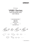
● Recommended Compact DC Power Supply (OMRON)
Model
Output capacity
Input voltage
S8VS-03024
24 VDC, 1.3 A
100 to 240 VAC
Note: The maximum power consumption of the Controller is
30 W (1.3 A at 24 VDC). The inrush current, however,
must be considered when selecting the power supply
capacity. A power supply with an output of 1.3 A min. at
24 VDC is recommended.
• Twisted-pair wire is recommended for the power line.
• To increase resistance to noise, ground to 100 or
less to an independent ground pole.
• Use a class 2 power supply.
DC power supply
Line filter
+ 24 V
Ferrite core
0V
Ground to a resistance of 100 or less
32
RFID System
User’s Manual
Type
SECTION 2
Installation, Connections, and Wiring
To reduce the influence of radiated noise, use a ferrite core.
Use the following procedure.
1. Wire the power supply and ground lines as normal.
ferrite core once so that the ferrite core does not move. The ferrite core should be within 10 cm of the
ID Controller.
SECTION 2 Connection and Wiring
2. Wrap the power supply lines and ground line together around the ferrite core. Loop them around the
3. Close the ferrite core until you hear it click into place.
Ferrite core
RFID System
User’s Manual
33
SECTION 2
Installation, Connections, and Wiring
Wiring I/O Lines
Precautions for Reset Signal Input
• Be sure that the input voltage does not exceed the maximum applicable voltage (26.4 V).
The device may malfunction if the rated voltage is exceeded.
• To improve noise resistance, install the input line 1 m or more away from high-voltage devices and
power lines.
SECTION 2 Connection and Wiring
Reset input
24 VDC
24 VDC
To error output
Precautions for Error Signal Output
• The maximum switching capacity for the output is 100 mA at 24 VDC (15% to +10%).
Do not use voltages or loads that exceed the switching capacity. Doing so may cause malfunctions.
• Use an auxiliary relay (24 VDC, 100 mA max.) to connect the output circuit.
Pin Arrangement
Pin No.
• Controller Terminal Arrangement
Name
V600 I/O
1
V680 I/O
RUN
2
BUSY
OUT3
3
ERROR
OUT4
4
OUT1
5
OUT2
6
COM_O
7
RST
8
TRG1
9
TRG2
10
COM_I
Terminal No.
1
Refer to External I/O Port for details on the external I/O port.
p. 16
34
RFID System
User’s Manual
2
3
4
5
6
7
8
9
10
SECTION 2
Installation, Connections, and Wiring
Mounting Cables
Use the connectors provided with the ID Controller.
Manufacturer
Cable
I/O lines
---
Connector
Crimp terminals
Model
---
Remarks
0.5
mm2
(equivalent to AWG 20)
MC1.5/10-STF-3.5
When connecting 2
lines to each terminal
---
AI0.5-8WH
Phoenix Contact
Crimping Tool
---
AI-TWIN2 0.5-8WH
SECTION 2 Connection and Wiring
When connecting 1 line
to each terminal
---
CRIMPFOX UD6
---
1. Attach the crimp terminals to the sections of the cable where the
sheath has been stripped.
2. Make sure the connector is facing the right direction and insert each
crimp terminal into the correct connector hole.
Connector: MC1.5/10-STF-3.5
(manufactured by Phoenix Contact)
3. Firmly tighten the connector cable screws.
Recommended tightening torque: 0.22 N·m
Use a small flat-blade screwdriver with a uniform thickness. Do not
use a standard screwdriver with a tapered end. A standard screwdriver will not fully insert into the hole.
Small flat-blade screwdriver
with a tip of uniform thickness.
4. Once all of the cables have been connected to the connector,
attach the connector to the ID Controller.
Align the cable connector with the connector on the ID Controller. Hold the connector
body and push the connector firmly into place, and then tighten the connector lock
screws.
Recommended tightening torque: 0.4 N·m
Lock screws
Removing the Connector
Completely loosen the two lock screws, hold the protruding part of the connector, and pull straight out. If
the connector is difficult to remove, press on the ID Controller while pulling on the connector.
Do not connect cables to the connector after attaching the connector to the ID Controller.
RFID System
User’s Manual
35
SECTION 2
Installation, Connections, and Wiring
RS-232C Port
Pin Arrangement
SECTION 2 Connection and Wiring
Pin No.
Symbol
9
2
3
RD
Signal direction
Input
Output
SG
---
---
SD
---
4
RS
5
CS
• ID Controller Terminal Arrangement
Signal name
5
1
Signal ground or common return line
Send data
---
Receive data
---
Clear to send
---
Request to send
9
6
The pin arrangement is different from that of the V680-CA1A. Use an RS-232C cable for the V680-CA5D@@V2.
Connections to Host Device
Example Connection to OMRON PLC
Host device
ID Controller
Pin No. Symbol
Pin No. Symbol
1
GR
GR
---
9
SG
SG
9
3
RD
SD
2
2
SD
RD
3
4
RS
RS
4
Model
Manufacturer
5
CS
CS
5
XW2Z-@@@T
OMRON
(Shield)
Recommended Cable
Note 1. Ground the shield at the host device side to prevent operation errors.
2. Short-circuit pins 4 (RS) and 5 (CS) inside the connector.
3. When creating the cable by yourself, be sure to read the User's Manual of PLC and confirm the signal name and pin arrangement.
Example Connection to IBM PC/AT or Compatible Computer via D-SUB 9-pin Connector
IBM PC/AT or compatible
ID Controller
Pin No. Symbol
Pin No. Symbol
---
GR
GR
---
5
SG
SG
9
2
RD
SD
2
3
SD
RD
3
7
RS
RS
4
Model
Manufacturer
8
CS
CS
5
XW2Z-@@@S-V
OMRON
(Shield)
Recommended Cable
Note 1. The interface cable will have a male connector on the ID Controller and a female connector on the IBM PC/AT or compatible.
2. Ground the shield at the host device to prevent operation errors.
3. When creating the cable by yourself, be sure to read the User's Manual of PC and confirm the signal name and pin arrangement.
Refer to Connections between ID Controllers (1:N) for information on 1:N connections.
p. 40
36
RFID System
User’s Manual
SECTION 2
Installation, Connections, and Wiring
Assembling and Connecting the Communications Connector
Have a connection cable and connector ready.
Controller end
OMRON
XM2S-0911
Hood
OMRON
XM3A-0921
Plug
Note: Hood and Plug of the following are not attached.
Hood: XM2S-0911 equivalent
Plug: XM3A-0921 equivalent
Assembling the Connector
1. Prepare the end of the cable as shown below.
40
35
Insert the cable into the cable bushing.
5
Unravel the braided shield for approximately 10 mm and fold it
SECTION 2 Connection and Wiring
OMRON
XM3B-0922-111
Socket
Host device end
back on the cable bushing.
Apply shield tape to the folded braided shield.
Conductors
Braided shield
Shield tape
Cable bushing
10±1
12
2. Solder the conductors to the plug pins.
Pin No.
9
Plug
Jumper
Cable bushing
Aluminum
tape
Symbol
SG
Signal name
Signal ground
2
SD
Send data
3
RD
Receive data
4 (See note.)
RS
Request to send
5 (See note.)
CS
Clear to send
Note: Short-circuit pins 4 (RS) and 5 (CS) with a jumper.
3. Attach housing A2 of the Hood to the Plug and secure the aluminum-taped portion with the cable
clamp.
Two, M2.6 lock screws
Housing A2
Cable clamp
Housing B2
4. Secure the two connector lock screws and put on housing B2 to complete the connector.
RFID System
User’s Manual
37
SECTION 2
Installation, Connections, and Wiring
Connecting and Disconnecting the Connector
• When connecting the connector, be sure to hold the connector by hand and fully insert the connector.
Secure the connector by tightening the two lock screws with a Phillips screwdriver.
Recommended tightening torque: 0.3 N·m
• When disconnecting the connector, completely loosen the two lock screws. Hold the protruding part
SECTION 2 Connection and Wiring
38
of the connector hood by hand and pull the connector straight out. If the connector is difficult to disconnect, hold the ID Controller with your hand while pulling on the connector.
Lock screws
RFID System
User’s Manual
SECTION 2
Installation, Connections, and Wiring
RS-422/RS-485 Port
Pin Arrangement
Pin No.
Name
Details
RDA()
Receive data
2
RDB(+)
Receive data
3
SDA()
Send data
4
SDB(+)
Send data
5
SG
Terminal No.
1
2
3
4
SECTION 2 Connection and Wiring
1
• ID Controller Terminal Arrangement
5
SG
Note: The port can be used as an RS-485 port if terminals 1 and
3, and 2 and 4 are short-circuited.
Connections to Host Device
RS-422 Connections
Host device
(Shield)
ID Controller
SDA()
RDA()
SDB()
RDB()
RDA()
SDA()
RDB()
SDB()
SG
SG
GR
Note: Ground the shield at the host device to prevent operation errors.
RS-485 Connections
ID Controller
Host device
RDA()
RDB()
+
SDA()
SDB()
SG
Note: Short-circuit terminals 1 and 3, and 2 and 4. Do not connect anything to the ID Controller signal ground.
RDA(−) RDB(+) SDA(−) SDB(+) SG
Reception
terminating
resistance
Transmission
terminating
resistance
Terminating resistance: 220 () for RS-422, 110 () for RS-485
Note: Turn ON terminating resistance only at the ID Controllers at the both ends
of the trunk cable. Turn OFF the terminating resistance at all ID Controllers
in between. Normal transmissions will not be possible if terminating
resistance is turned ON for the ID Controllers in between.
RFID System
User’s Manual
39
SECTION 2
Installation, Connections, and Wiring
Connections between ID Controllers (1:N)
RS-232C Connection to the Host Device
SW 6: ON
(terminating
resistance)
RS-232C
SW 6: OFF
(no terminating
resistance)
SW 6: OFF
(no terminating
resistance)
RS-422
RS-422
SW 6: ON
(terminating
resistance)
RS-422
Host device
SECTION 2 Connection and Wiring
ID Controller
ID Controller
Max. length: 15 m
ID Controller
ID Controller
Total length: 500 m max.
Pin No. Symbol
Pin No. Symbol
Pin No. Symbol
Pin No. Symbol
1
RDA(−)
1
RDA(−)
1
RDA(−)
1
RDA(−)
2
RDB(+)
2
RDB(+)
2
RDB(+)
2
RDB(+)
3
SDA(−)
3
SDA(−)
3
SDA(−)
3
SDA(−)
4
SDB(+)
4
SDB(+)
4
SDB(+)
4
SDB(+)
5
SG
5
SG
5
SG
5
SG
SW 6: OFF
(no terminating
resistance)
SW 6: ON
(terminating
resistance)
RS-232C
RS-485
SW 6: OFF
(no terminating
resistance)
RS-485
SW 6: ON
(terminating
resistance)
RS-485
Host device
ID Controller
ID Controller
Max. length: 15 m
ID Controller
ID Controller
Total length: 500 m max.
Pin No. Symbol
Pin No. Symbol
Pin No. Symbol
Pin No. Symbol
1
RDA(−)
1
RDA(−)
1
RDA(−)
1
RDA(−)
2
RDB(+)
2
RDB(+)
2
RDB(+)
2
RDB(+)
3
SDA(−)
3
SDA(−)
3
SDA(−)
3
SDA(−)
4
SDB(+)
4
SDB(+)
4
SDB(+)
4
SDB(+)
5
SG
5
SG
5
SG
5
SG
Note: Short-circuit terminals 1 and 3, and 2 and 4 to use RS-485 communication.
Refer to Connections to Host Device for information on RS-232C connections between the host device and ID Controllers.
p. 36
If the first communications received by an ID Controller are via the RS-232C interface, reception of RS-422/RS-485
communications will be prohibited. If the first communications are received via RS-422/RS-485, reception of RS-232C
communications will be prohibited. Therefore, when changing the system configuration of an ID Controller, always turn
OFF the power supply before changing the connections.
40
RFID System
User’s Manual
SECTION 2
Installation, Connections, and Wiring
RS-422 Connection to Host Device
SW 6: OFF
(no terminating
resistance)
SW 6: OFF
(no terminating
resistance)
Host device
(terminating
resistance
connected)
RS-422
RS-422
SW 6: OFF
(no terminating
resistance)
RS-422
RS-422
ID Controller
ID Controller
Total length: 500 m max.
Pin No. Symbol
Pin No. Symbol
Pin No. Symbol
Pin No. Symbol
1
RDA(−)
1
RDA(−)
1
RDA(−)
1
RDA(−)
2
RDB(+)
2
RDB(+)
2
RDB(+)
2
RDB(+)
3
SDA(−)
3
SDA(−)
3
SDA(−)
3
SDA(−)
4
SDB(+)
4
SDB(+)
4
SDB(+)
4
SDB(+)
5
SG
5
SG
5
SG
5
SG
SECTION 2 Connection and Wiring
ID Controller
ID Controller
SW 6: ON
(terminating
resistance)
Refer to RS-422 Connections for information on RS-422 connections between the host device and ID Controllers.
p. 39
If the first communications received by an ID Controller are via the RS-232C interface, reception of RS-422/RS-485
communications will be prohibited. If the first communications are received via RS-422/RS-485, reception of RS-232C
communications will be prohibited. Therefore, when changing the system configuration of an ID Controller, always turn
OFF the power supply before changing the connections.
RS-485 Connection to the Host Device
SW 6: OFF
(no terminating
resistance)
SW 6: OFF
(no terminating
resistance)
Host device
(terminating
resistance
connected)
RS-485
RS-485
ID Controller
SW 6: OFF
(no terminating
resistance)
RS-485
ID Controller
SW 6: ON
(terminating
resistance)
RS-485
ID Controller
ID Controller
Total length: 500 m max.
Pin No. Symbol
Pin No. Symbol
Pin No. Symbol
Pin No. Symbol
1
RDA(−)
1
RDA(−)
1
RDA(−)
1
RDA(−)
2
RDB(+)
2
RDB(+)
2
RDB(+)
2
RDB(+)
3
SDA(−)
3
SDA(−)
3
SDA(−)
3
SDA(−)
4
SDB(+)
4
SDB(+)
4
SDB(+)
4
SDB(+)
5
SG
5
SG
5
SG
5
SG
Note: Short-circuit terminals 1 and 3, and 2 and 4 to use RS-485 communications.
Refer to RS-485 Connections for information on RS-485 connections between the host device and ID Controllers.
p. 39
If the first communications received by an ID Controller are via the RS-232C interface, reception of RS-422/RS-485
communications will be prohibited. If the first communications are received via RS-422/RS-485, reception of RS-232C
communications will be prohibited. Therefore, when changing the system configuration of an ID Controller, always turn
OFF the power supply before changing the connections.
RFID System
User’s Manual
41
SECTION 2
Installation, Connections, and Wiring
Mounting Cables
Use the connectors provided with the ID Controller.
Cable
Manufacturer
Model
Remarks
---
---
0.5 mm2 (equivalent to AWG 20)
RS-422 lines
Connector
Crimp terminals
MC1.5/5-STF-3.5
SECTION 2 Connection and Wiring
When connecting 1 line
to each terminal
When connecting 2 lines
to each terminal
---
AI0.5-8WH
Phoenix Contact
Crimping Tool
---
AI-TWIN2 0.5-8WH
---
CRIMPFOX UD6
---
1. Attach the crimp terminals to the sections of the cable where the
sheath has been stripped.
2. Make sure the connector is facing the right direction and insert each
crimp terminal into the correct connector hole.
Connector: MC1.5/5-STF-3.5
(manufactured by Phoenix Connector)
3. Firmly tighten the connector cable screws.
Recommended tightening torque: 0.22 N·m
Use a small flat-blade screwdriver with a uniform thickness. Do not use a standard screwdriver with a tapered end. A standard screwdriver will not fully
insert into the hole.
Small flat-blade screwdriver
with a tip of uniform thickness.
4. Once all of the cables have been connected to the connector,
attach the connector to the ID Controller.
Align the cable connector with the connector on the ID Controller. Hold the connector
body and push the connector firmly into place, and then tighten the connector lock
screws.
Recommended tightening torque: 0.4 N·m
Lock screws
Removing the Connector
Completely loosen the two lock screws, hold the protruding part of the connector, and pull straight out. If the connector
is difficult to remove, press on the ID Controller while pulling on the connector.
Do not connect cables to the connector after attaching the connector to the ID Controller.
42
RFID System
User’s Manual
SECTION 2
Installation, Connections, and Wiring
USB Port
The USB port is connected to a USB cable (Series A-Mini USB series B connectors).
The USB port is not a control port. Always use the RS-232C port or RS-422/RS-485 port for system configuration.
p. 21
SECTION 2 Connection and Wiring
Pin Arrangement
• Controller Terminal Arrangement
Pin No.
Name
Description
1
VBUS
Power supply
2
D
USB data ()
3
D+
USB data (+)
5
GND
Ground
Terminal No.
Pin No. Symbol
1 2 3
4 5
Pin No. Symbol
1
VBUS
1
VBUS
2
D−
2
D−
3
D+
3
D+
4
GND
5
GND
-
GR
-
GR
Connecting and Disconnecting Connectors
1. Connect the Mini USB series B end of the connector to the ID Controller.
Series B end
Series A end
A cap is attached to the connectors at shipment. Leave this cap on if USB is not being used to prevent dust or foreign
matter from entering the connectors and to prevent static electricity.
Removing Connectors
Hold the base of the connector and pull straight out. If the connector is difficult to remove, press the ID Controller while
pulling on the connector.
RFID System
User’s Manual
43
SECTION 2
Installation, Connections, and Wiring
2. Connect the Series A end of the connector to the host device.
Align the connectors and insert the connector straight in.
SECTION 2 Connection and Wiring
3. Removing the Connector from the Host Device
Close the software on the host device and pull the connector straight out.
If the connector is removed while the software is running on the host
device, the software will not operate properly, which will cause a fatal
error.
Installing Ferrite Cores
Noise resistance may be low because USB is being used.
Noise resistance can be improved by using the ferrite core listed below.
Manufacturer
SEIWA
Model
E04SR301334
1. Install the ferrite core listed above to the cable.
Attach the ferrite core to the Mini USB Series B end. Close the ferrite core until it
snaps shut. The ferrite core should be 10 cm or less from the connector.
44
RFID System
User’s Manual
10 cm max.
SECTION 2
Installation, Connections, and Wiring
Installing the USB Driver
When connecting the ID Controller to the host device for the first time, the USB driver must be installed
on the computer.
Downloading the USB Driver
Download the USB driver for the V680-CA5D@@-V2.
Installing the USB Driver on the Computers
The USB Driver can be used on Windows 2000 or XP. Install the driver on the host device following the
procedure corresponding to the operating system being used.
Operation may not be possible on other operating systems.
Windows 2000
SECTION 2 Connection and Wiring
For details, ask your OMRON representative for information on the USB driver.
1. Turn ON the power to the computer and start Windows 2000.
2. Connect the ID Controller to the computer via USB.
Refer to USB Port for information on the connection method.
p. 43
The following dialog box will be displayed when the ID Controller is connected via USB.
3. Once the following dialog box has been displayed, click the Next Button.
RFID System
User’s Manual
45
SECTION 2
Installation, Connections, and Wiring
4. Select Search for a suitable driver for my device (recommended) and click the Next Button.
SECTION 2 Connection and Wiring
5. Select Specify a location and click the Next Button.
6. Click the Browse Button and select the folder where the downloaded V680-CA5D_100.inf is to be
saved.
46
RFID System
User’s Manual
SECTION 2
Installation, Connections, and Wiring
7. Click the Next Button.
SECTION 2 Connection and Wiring
The following dialog box will be displayed when the software installation has been completed.
8. Click the Finish Button.
RFID System
User’s Manual
47
SECTION 2
Installation, Connections, and Wiring
Checking Installation
Use the following procedure to confirm that the driver has been correctly installed.
1. Connect the ID Controller to the computer via USB.
SECTION 2 Connection and Wiring
2. Select Settings - Control Panel - System from the Windows Start Menu.
3. Click the Device Manager Button on the Hardware Tab Page.
4. Select Ports (COM & LPT) and check that OMRON RFID USB COM is displayed.
If the driver is correctly installed the property window for the V680-CA5D@@-V2 will be as follows:
Communications with the ID Controller can be performed with the COM number displayed in parentheses after OMRON RFID
USB COM.
48
RFID System
User’s Manual
SECTION 2
Installation, Connections, and Wiring
Windows XP
1. Turn ON the power to the computer and start Windows XP.
SECTION 2 Connection and Wiring
2. Connect the ID Controller to the computer via USB.
Refer to USB Port for details on the connection method.
p. 43
Wait for the following dialog box to be displayed.
3. When the following dialog box is displayed, select Install from a list or specific location (Advanced) and
click the Next Button.
4. Click the Browse Button and select the folder in which the downloaded V680-CA5D_100.inf file is to be
saved. Then click the Next Button.
RFID System
User’s Manual
49
SECTION 2
Installation, Connections, and Wiring
5. Click the Continue Button.
SECTION 2 Connection and Wiring
When the following dialog is displayed, installation is completed.
6. Click the Finish Button.
50
RFID System
User’s Manual
SECTION 2
Installation, Connections, and Wiring
Checking Installation
Use the following procedure to confirm that the driver has been correctly installed.
1. Connect the ID Controller to the computer via USB.
SECTION 2 Connection and Wiring
2. Select Control Panel - Performance and Maintenance from the Windows Start Menu.
3. Click the System Icon.
4. Click the Device Manager Button on the Hardware Tab Page.
5. Select Ports (COM & LPT) and check that OMRON RFID USB COM is displayed.
If the driver is correctly installed the property window for the V680-CA5D@@-V2 will be as follows:
Communications with the ID Controller can be performed with the COM number displayed in parentheses after OMRON RFID
USB COM.
RFID System
User’s Manual
51
SECTION 2
Installation, Connections, and Wiring
Windows Vista
1. Turn ON the power to the personal computer and start Windows Vista.
SECTION 2 Connection and Wiring
2. Connect the ID Controller to the computer via USB.
For details on connection methods, refer to USB Port.
p. 43
Wait for the following window to be displayed.
3. When the following window is displayed, select Locate and install driver software
(recommended) Button.
52
RFID System
User’s Manual
SECTION 2
Installation, Connections, and Wiring
4. When the following window is displayed, select I don’t have the disc. Show me other options. Button.
SECTION 2 Connection and Wiring
5. When the following window is displayed, select Browse my computer for driver software
(advanced) Button.
RFID System
User’s Manual
53
SECTION 2
Installation, Connections, and Wiring
6. Click the Browse Button, and select the folder in which the downloaded file V680-CA5D_200.inf is
saved. Then click the Next Button.
SECTION 2 Connection and Wiring
7. When the following window is displayed, select Install this driver software anyway Button.
When the following window is displayed, installation is completed.
8. Click the Close Button.
54
RFID System
User’s Manual
SECTION 2
Installation, Connections, and Wiring
Checking Installation
Check that the driver is correctly installed.
1. Connect the ID Controller to the personal computer via USB.
SECTION 2 Connection and Wiring
2. Select Control Panel - System from the Windows Start Menu.
3. Click the Device Manager Button.
4. Select Ports (COM & LPT), and check that OMRON RFID USB COM is displayed.
If the driver is correctly installed, the property window for the V680-CA5D will be displayed as follows:
Communications with the ID Controller can be performed with the COM number displayed in parentheses after OMRON RFID
USB COM.
RFID System
User’s Manual
55
SECTION 2
Installation, Connections, and Wiring
Windows 7
1. Turn ON the power to the personal computer and start Windows 7.
SECTION 2 Connection and Wiring
2. Connect the ID Controller to the computer via USB.
Refer to USB Port for information on the connection method.
p. 43
3. Select Settings - Control Panel - System and Security from the Windows Start Menu.
4. Click the Device Manager Button.
56
RFID System
User’s Manual
SECTION 2
Installation, Connections, and Wiring
5. Right-click the Other devices - V680-CA5D and click the Properties.
SECTION 2 Connection and Wiring
6. Click the Update Driver Button.
7. Once the following dialog box has been displayed, click the Browse my computer for driver software
Button.
RFID System
User’s Manual
57
SECTION 2
Installation, Connections, and Wiring
8. Click the Browse Button and select the folder where the downloaded V680-CA5D_100.inf is to be
saved. Then click the Next Button.
SECTION 2 Connection and Wiring
9. Click the Install this driver software anyway Button.
The following dialog box will be displayed when the software installation has been completed.
10. Click the Close Button.
58
RFID System
User’s Manual
SECTION 2
Installation, Connections, and Wiring
Checking Installation
Use the following procedure to confirm that the driver has been correctly installed.
1. Turn ON the power to the personal computer and start Windows 7.
SECTION 2 Connection and Wiring
2. Connect the ID Controller to the personal computer via USB.
Refer to USB Port for information on the connection method.
p. 43
3. Select Settings - Control Panel - System and Security from the Windows Start Menu.
4. Click the Device Manager Button.
RFID System
User’s Manual
59
SECTION 2
Installation, Connections, and Wiring
5.
SECTION 2 Connection and Wiring
6. Select Ports (COM & LPT), and check that OMRON RFID USB COM is displayed.
If the driver is correctly installed, the property window for the V680-CA5D will be displayed as follows:
Communications with the ID Controller can be performed with the COM number displayed in parentheses after OMRON RFID
USB COM.
60
RFID System
User’s Manual
SECTION 2
Installation, Connections, and Wiring
Antenna Port
Connecting and Removing the Connector
matching the white mark on the ID Controller with the white mark on
the connector.
2. Press the connector in vertically until it locks.
Ring
Be sure to hold onto the base of the connector. The connector will not lock if
Base of connector
the ring is held.
SECTION 2 Connection and Wiring
1. Hold the base of the connector, and insert the connector while
3. To remove the connector, hold onto the ring and pull the connector
straight out.
The cable cannot be removed if the base of the connector is held. Never
pull excessively on the cable. Doing so will cause broken wires and damage.
Ring
Do not remove or connect the connector when the power is turned ON.
Doing so may cause malfunctions.
RFID System
User’s Manual
61
SECTION 2
Installation, Connections, and Wiring
MEMO
SECTION 2 Connection and Wiring
62
RFID System
User’s Manual
SECTION 3
Preparations for Communications
RF Tag Memory Setting
82
Trial Operation
88
RFID System
User’s Manual
Preparations for Communications
64
SECTION 3
Switch Settings
63
SECTION 3
Preparations for Communications
Switch Settings
Opening the Cover
Open the cover by inserting a small screwdriver into the groove on the cover.
Controller Number Switches (SW1, SW2)
DIP Switch (SW3)
DIP Switch (SW4)
SECTION 3 Switch Settings
Mode Switch (SW5)
Terminating
Resistance
Switch (SW6)
Setting Methods
Use the provided screwdriver to make switch settings as shown in the following diagram.
Rotary Switch Settings (SW1, SW2)
DIP Switch Settings (SW3, SW4)
Toggle Switch Settings (SW5, SW6)
Default Settings
Name
64
SW1
Controller number upper digit (0 to 9)
0
SW2
Controller number lower digit (0 to 9)
0
RFID System
User’s Manual
Default
setting
Description
Controller No. 00
Reference
p. 66
SECTION 3
Preparations for Communications
Name
Default
setting
Description
SW3, pin 1
SW enable switch
OFF
DIP Switches enabled
SW3, pin 2
Reserved by system.
OFF
(Not used)
Baud rate: 9600 bps
Baud rate setting 1
OFF
SW3, pin 4
Baud rate setting 2
OFF
SW3, pin 5
Data length
OFF
Data length: 7 bits
SW3, pin 6
Parity 1
OFF
Parity: Even
SW3, pin 7
Parity 2
OFF
SW3, pin 8
Stop bit length
OFF
Stop bits: 2
SW3, pin 9
Communications protocol
OFF
1:1
SW3, pin 10
Command system
OFF
V680 commands
Distance level measurement
p. 67
SW4, pin 1
Test Mode switch setting 1
OFF
SW4, pin 2
Test Mode switch setting 2
OFF
SW4, pin 3
Test Mode switch setting 3
OFF
SW4, pin 4
Antenna specification for test execution
OFF
Antenna 1
SW4, pin 5
Write verification
OFF
With write verification
SW4, pin 6
Lower trigger execution setting
OFF
None
SW4, pin 7
Write protection function disable
OFF
Enabled
OFF
Connection to antennas other
than the V680-H01 (See Note1.)
SW4, pin 8
V680-H01 Antenna connection setting
SW4, pin 9
Run Mode setting
OFF
Command Execution Mode
SW4, pin 10
High-speed Data Transmission setting
OFF
Normal mode (See Note2.)
SW5
Mode switch
OFF
Run Mode
SW6
Terminating resistance
OFF
No terminating resistance
p. 68
SECTION 3 Switch Settings
SW3, pin 3
Reference
p. 70
Note1. Set this pin to OFF when the V680-H01-V2 Antenna is connected.
For details, refer to SW4, pin 8 (V680-H01 Antenna connection setting) of this chapter.
p. 69
2. When using V680S-D8KF@@ RF Tags, the Normal Mode communications speed will be used even if the High-speed
Mode is set.
RFID System
User’s Manual
65
SECTION 3
Preparations for Communications
Controller Number Switch Settings (SW1, SW2)
Controller Numbers
If more than one Controller is connected to a single host device, the host device must be able to distinguish them. For this reason, a different Controller number must be set for each Controller.
Controller numbers are included in 1:N protocol commands and responses. Communications are not
possible if the Controller numbers are not set correctly.
SW1 and SW2 are enabled only when the DIP switch is enabled (i.e., when pin 1 on SW3 is OFF). If the internal settings are enabled (i.e., if pin 1 on SW3 is ON), the values specified by the PARAMETER SET (SP) command will be
enabled.
Setting Controller Numbers
SW1
SW2
Upper digit
Lower digit
0
0
0
SW1
SW1
0
1
1
9 0 1
0
2
2
9 0 1
0
3
3
0
4
4
4 5 6
4 5 6
0
5
5
SW2
SW2
0
6
6
0
7
7
9 0 1
9 0 1
0
8
8
0
9
9
1
0
10
1
1
11
Controller No.
30
3
1
31
3
2
Setting prohibited
3
3
Setting prohibited
:
:
:
9
9
Setting prohibited
7 8
7 8
7 8
7 8
4 5 6
0
2 3
3
Controller No. 0
2 3
:
29
2 3
:
9
2 3
:
2
Setting Examples
4 5 6
SECTION 3 Switch Settings
p. 240
Controller No. 17
The Controller number switch is factory-set to 00.
Do not set the Controller number switch to between 32 and 99.
When rotary switch SW1 is set to 8, the ID Controller will be in Host Communications Trigger Send Mode. If the mode
switch is turned OFF in this mode, a response frame will be sent to the host device.
p. 80
66
RFID System
User’s Manual
SECTION 3
Preparations for Communications
DIP Switch Settings (SW3, SW4)
SW3, Pin 1 (SW Enable Switch)
SW3, pin 1
Description
OFF
DIP switch enabled
ON
Internal settings enabled
Note: SW1, SW2, SW3 (pins 3 to 9), and SW4 (pins 5 to 7) are enabled only when the DIP switches
are enabled.
When the internal settings are enabled, the values specified by the TR and SP commands are valid.
The default values will be enabled if values have not been specified using the TR and SP commands.
SECTION 3 Switch Settings
p. 238, p. 240
SW3, Pin 2 (RF Tag Memory Setting)
SW3, pin 2
Description
OFF
Standard Mode
ON
CA1D Mode
SW3, Pins 3 and 4 (Baud Rate)
SW3, pin 3
SW3, pin 4
OFF
ON
Description
OFF
9,600 bps
ON
19,200 bps
OFF
38,400 bps
ON
115,200 bps
SW3, Pin 5 (Data Length)
SW3, pin 5
Description
OFF
7 bits
ON
8 bits
SW3, Pins 6 and 7 (Parity)
SW3, pin 6
SW3, pin 7
OFF
ON
Description
OFF
Even
ON
None
OFF
Odd
ON
Even
SW3, Pin 8 (Stop Bit Length)
SW3, pin 8
Description
OFF
2 bits
ON
1 bit
SW3, Pin 9 (Communications Protocol)
SW3, pin 9
Description
OFF
1:1
ON
1:N
RFID System
User’s Manual
67
SECTION 3
Preparations for Communications
SW3, Pin 10 (Command System)
SW3, pin 10
Description
OFF
V680 commands
ON
V600 commands
SW4, Pins 1, 2, and 3 (Maintenance Mode Switch Settings)
SW4,
pin 1
SW4,
pin 2
SW4,
pin 3
OFF
OFF
SECTION 3 Switch Settings
OFF
ON
OFF
ON
ON
Description
Distance Level Measurement Mode
ON
RF Tag Communications Test Mode
OFF
Speed Level Measurement Mode, Read
ON
Speed Level Measurement Mode, Write
OFF
Noise Level Measurement Mode
OFF
Communications Success Rate Measurement Mode
ON
Host Communications Monitor Mode
Maintenance Mode cannot be used when a V680-H01 or V680-H01-V2 Antenna is used.
For details, refer to Maintenance Mode.
p. 73
SW4, Pin 4 (Antenna Specification)
SW4, pin 4
Description
OFF
Antenna 1
ON
Antenna 2
Note: This setting is valid only in Maintenance Mode.
SW4, Pin 5 (Write Verification)
SW4, pin 5
Description
OFF
With write verification
ON
Without write verification
SW4, Pin 6 (Lower Trigger Execution)
SW4, pin 6
Description
OFF
None
ON
Enabled (on rising edge)
Note: This setting is valid only when pin 10 on DIP switch SW3 (command system) is ON.
SW4, Pin 7 (Write Protection Function)
SW4, pin 7
68
RFID System
User’s Manual
Description
OFF
Enabled
ON
Disabled
SECTION 3
Preparations for Communications
SW4, pin 8 (V680-H01 Antenna connection setting)
SW4, pin 8
Description
OFF
Connection to antennas other than the V680-H01(See Note.)
ON
Allows connection of the V680-H01 Antenna.
Note: Set this pin to OFF when the V680-H01-V2 Antenna is connected.
The V680-H01 or V680-H01-V2 Antenna can be connected only to the V680-CA5D01-V2 ID Controller. It cannot be
used with the V680-CA5D02-V2 ID Controller.
Differences between the V680-H01 and V680-H01-V2
V680-H01
SECTION 3 Switch Settings
Model
V680-H01-V2
Externals
(The size is the same)
Indicators
1 LED are in front of the Antenna.
12 LED are in front of the Antenna.
DIP switch
None
4 DIP switches are in the back of the Antenna.
Maintenance Mode
The maintenance mode cannot be used.
The maintenance mode can be used.
Setting of DIP switch
of V680-CA5D@@
SW4, pin 8 : ON
SW4, pin 8 : OFF
Setting of DIP switch of V680-H01-V2
ON
ON
1 2 3 4
SW1
Setting switch
protection cover
Setting
Note: Please attach a setting switch protection cover after setting switch.
Function
Default setting
SW1-1
Controller selection
OFF:V680-CA5D01-V@, CS1W-V680C11, or CJ1W-V680C11
ON: V680-CA1D/-CA2D See Note.
OFF
SW1-2
RF Tag selection
OFF:V680-D1KP@@ (EEPEOM RF Tags)
ON: V680-D@KF@@ (FRAM RF Tags)
OFF
SW1-3
Reserved by System (Always set this Switch to OFF.)
---
SW1-4
Reserved by System (Always set this Switch to OFF.)
---
Note: Only when the V680-D1KP58HT is used, it is possible to connect it with the V680-CA1D/-CA2D.
When the V680-CA5D01-V@, CS1W-V680-C11 and CJ1W-V680C11 is used, set SW1-1 of the antenna to turning off.
For details, refer to either of the following User’s Manuals.
Cat. No. Z262 V680 Series User's Manual for Amplifiers, Antennas, and RF Tags (EEPROM)
Cat. No. Z248 V680 Series User's Manual for Amplifiers, Antennas, and RF Tags (FRAM)
RFID System
User’s Manual
69
SECTION 3
Preparations for Communications
SW4, Pin 9 (Run Mode)
SW4, pin 9
Description
OFF
Command Execution Mode
ON
Self-execution Mode
Self-execution Mode will not work if pin 10 on DIP switch SW3 (V600 commands) is ON.
SW4-10 (High-speed Data Transmission setting)
SW4, pin 8
Description
SECTION 3 Switch Settings
OFF
Normal mode
ON
High-speed mode
The high-speed mode cannot be used with the V680-H01 or V680-H01-V2 Antenna.
For information on communication times, refer to RF Tag Communications Time and Turn Around Time (Reference).
When using multi-access, selective, or FIFO communications options, normal-mode communications speed will be
used regardless of this setting.
p. 267
When using V680S-D8KF@@ RF Tags, the Normal Mode communications speed will be used even if the High-speed
Mode is set.
Mode Switch Setting
SW5
Description
OFF
Run Mode
ON
Maintenance Mode
Maintenance Mode cannot be used when a V680-H01 or V680-H01-V2 Antenna is used.
Terminating Resistance
If two or more ID Controller are connected to one host device, be sure to turn ON the terminating resistance of only the Controllers or host devices at each end of the serial connection and turn OFF the terminating resistance of any other device. Incorrect settings will result in unstable operation.
This switch is used to set internal terminating resistance.
SW6
70
RFID System
User’s Manual
Description
OFF
Terminating resistance OFF
ON
Terminating resistance ON
SECTION 3
Preparations for Communications
Operation Modes
The V680-CA5D@@-V2 ID Controller has two operation modes: Run Mode and Maintenance Mode.
Run Mode
There are two Run Modes: Command Execution Mode and Self-execution Mode.
The Run Mode at startup (when the power is turned ON) can be selected using pin 9 on SW4. The
mode can also be changed by executing an OPERATION MODE CHANGE command (MO) from the
host device.
Power ON
SECTION 3 Switch Settings
SW4, pin 9 OFF
Command
Execution Mode
OPERATION MODE CHANGE command (MO)
SW4, pin 9 ON
Self-execution
Mode
Command Execution Mode
In this mode, commands are executed from the host device to perform operations and the results are
returned to the host device as responses.
Host device
Command
ID Controller
Antenna
RF Tag
Response
RFID System
User’s Manual
71
SECTION 3
Preparations for Communications
Self-execution Mode
The operation conditions must be registered in Command Execution Mode using the OPERATION CONDITION SET
(SE) command.
p. 163
Self-completion operation can be performed so that communications with RF Tags are automatically
executed according to the operation conditions registered in the ID Controller, the results of communications with the RF Tags are judged (judgment conditions), and the results are output to the four exterSECTION 3 Switch Settings
nal outputs (OUT1, OUT2, OUT3, and OUT4) or the RS-232C port. A very simple system can be built
because the ID Controller does not need to be controlled from the host device.
The following operation conditions can be registered.
Item
Settings
Execution processing
Only RF Tag communications commands can be used.
The only RA and RI communications modes can be used.
Judgment conditions
One of the following can be set for each output.
1) Output judgment of RF Tag communications results.
2) Output results of comparing response data to set data.
Result output
The following five outputs can be set for when judgment conditions have been met. (See note.)
Judgment conditions can be set for each output.
1) Output to OUT1. The output time can be set.
2) Output to OUT2. The output time can be set.
3) Output to OUT3. The output time can be set.
4) Output to OUT4. The output time can be set.
5) Return the response to the host computer.
Note: There are 2 external outputs (OUT1 and OUT2) if the I/O arrangement is set to the same I/O arrangement as the
V600(V680-CA5D@@-V2).
Self-execution Mode will not work if the V600 command system is set. For the V680 command system, either 2 outputs
(default setting of 0) or 4 outputs can be switched. Refer to PARAMETER SET (SP) for details.
p. 157
The operation conditions are stored in the ID Controller's internal non-volatile memory and do not need to be set again
each time the power is turned ON.
72
RFID System
User’s Manual
SECTION 3
Preparations for Communications
Maintenance Mode
Maintenance Mode is used to perform tests corresponding to actual operation. Maintenance Mode can
be used to simply measure the communications performance in a particular environment, making it
useful for checking during system installation and operation.
The following five modes are available within Maintenance Modes.
Description
Measures the Antenna and RF Tag installation distance in relation to the RF Tag interrogation
zone and displays the result on the bar indicator.
RF Tag Communications Test
Mode
Communications with RF Tags and displays the end code on the monitor display to indicate
the result.
Speed Level Measurement
Mode
Measures the number of times that communications can be performed consecutively based on
the speed RF Tags pass through the Antenna interrogation zone and displays the result as a
speed level on the bar indicator and monitor display.
Noise Level Measurement
Mode
Measures the ambient noise level in the installation environment and displays the result on the
monitor display.
Communications Success
Rate Measurement Mode
Executes communications with a RF Tag 100 times with no retries and displays the result as a
communications success rate on the monitor display.
Host Communications Monitor Outputs the communications commands and responses exchanged with the host device from
Mode
the USB port.
Maintenance Mode cannot be used when the V680-H01 Antenna is connected.
SECTION 3 Switch Settings
Mode
Distance Level Measurement
Mode
Maintenance Mode cannot be used when the V680-H01-V2 Antenna is connected and SW1 pin 1 is turned OFF.
Regardless of the mode setting, the Unit will operate in RF Tag Communications Test Mode.
Maintenance Mode can be used with version 2.2 or newer when SW1 pin 1 is turned OFF on the V680-H01-V2. Use the
VERSION READ (VS) command to read the product version. For details on the VERSION READ (VS) command, refer
to VERSION READ (VS) under V680 Commands or V600 Commands in Section 3 Commands.
p. 176, p. 233
Using Maintenance Mode
1. Set Test Mode.
Set pins 1 to 3 on DIP switch SW4 to the Test Mode to be used.
p. 68
2. Set the Mode Switch (SW5).
Turn ON the power and turn ON the mode switch (SW5) to change to Maintenance Mode.
If the power is turned ON with the mode switch (SW5) already set to
ON, the Controller will enter Maintenance Mode.
If the power supply is turned ON with the mode switch (SW5) turned ON, the ID Controller will start in Maintenance
Mode. If Maintenance Mode is entered during command execution (other than in Host Communications Monitor Mode),
all current processing will be canceled. If a write command was being executed, part of the contents of the RF Tag may
have been overwritten.
To switch to another mode, change the Test Mode on pins 1 to 3 on DIP switch SW4 then turn ON the mode switch
(SW5).
RFID System
User’s Manual
73
SECTION 3
Preparations for Communications
Distance Level Measurement Mode
Distance Level Measurement Mode can be used to easily check the installation positions of Antennas
and RF Tags without connecting to a host device. In this mode, the monitor display and bar indicator
show how far the installation distance between Antenna and RF Tags is in relation to the interrogation
zone.
The distance level changes dramatically depending on the ambient environment. Use it as a guide for the installation
position and perform sufficient tests in Run Mode in the actual installation environment. Levels higher than distance
level 4 may not be displayed, but this does not indicate an error and performance in Run Mode will not be affected.
SECTION 3 Switch Settings
1. Change to Distance Level Measurement Mode.
SW4, pin 1: OFF, SW4, pin 2: OFF, SW4, pin 3: OFF, SW5: ON
2. Place RF Tags within the Antenna interrogation zone.
Distance level 1
A right picture is an image at the distance level.
RF Tag
2
3
The level indication might not become it in the order from 1 to 6 according to the combination of RF Tag and the antenna.
4
5
6
Antenna
3. The distance level will be displayed on the bar indicator and monitor display.
The level at which normal reading was possible will be displayed between 01 and 06. If there is no RF Tag in the Antenna’s interrogation zone, “--” will be displayed. The measurement result is also output from the USB port.
Monitor display
Bar indicator
1
Output from the USB Port
The distance level and Antenna channel are output from the USB port.
DL 06 1 0 * [CR]
Resend Flag (Always "0".)
Antenna channel ("1": channel 1, "2": channel 2)
Distance level ("01" to "06")
74
RFID System
User’s Manual
6
SECTION 3
Preparations for Communications
Speed Level Measurement Mode (Read/Write)
Speed Level Measurement Mode can be used to check the RF Tag movement speed and applicable
number of bytes without connecting to a host device. In this mode, the margin available for the RF Tag
movement speed in relation to the number of bytes being accessed is displayed on the bar indicator.
The Speed Level Measurement Mode simulates writing data. Actually data is not written to the RF Tag.
The speed level is measured for the number of test bytes set in advance using the PARAMETER SET (SP) command.
Refer to PARAMETER SET (SP) for details.
SECTION 3 Switch Settings
p. 157
1. Change to Speed Level Measurement Mode.
Reading
SW4, pin 1: OFF, SW4, pin 2: ON, SW4, pin 3: OFF, SW5: ON
Writing
SW4, pin 1: OFF, SW4, pin 2: ON, SW4, pin 3: ON, SW5: ON
2. Move the RF Tags.
Speed level 3
Travel
RF Tag
3
2
1
Antenna
3. The speed level will be displayed on the bar indicator and monitor
display.
Monitor display
The number of successful communications between 01 and 99 is displayed on the
monitor display. (“--” is displayed to indicate standby status.) The display will show
99 even if more than 99 successful communications were made. “EE” will be dis-
Bar indicator
1
6
played if the first communication after the RF Tag entered the interrogation zone
fails. The bar indicator will show the speed level. One LED in the bar indicator will
light for each 2 successful communications (all six LEDs will be lit after 12 successful communications). The measurement result
is also output from the USB port.
Output from the USB Port
The number of successful communications and the Antenna channel are output from the USB port.
SL 99 1 0 * [CR]
Resend Flag (Always "0".)
Antenna channel ("1": channel 1, "2": channel 2)
Number of continuous successful communications ("01" to "99" or "EE")
RFID System
User’s Manual
75
SECTION 3
Preparations for Communications
Noise Level Measurement Mode
Noise Level Measurement Mode enables checking spatial noise, noise sources, and the effectiveness
of noise countermeasures without connecting to a host device. This mode measures the noise level in
the surrounding environment and displays the result on the monitor display. A noise level between 00
and 99 can be output from the USB port as the result.
1. Change to the Noise Level Measurement Mode.
SW4, pin 1: ON, SW4, pin 2: OFF, SW4, pin 3: OFF, SW5: ON
SECTION 3 Switch Settings
2. Measuring the noise level will be started.
Antenna
3. The noise level measurement results will be displayed on the
monitor display.
Monitor display
The noise in the surrounding environment is displayed between “00” and “99”.
The measurement result is also output from the USB port.
Output from the USB Port
The noise level and Antenna channel are output from the USB port.
NL 00 1 0 * [CR]
Resend Flag (Always "0".)
Antenna channel ("1": channel 1, "2": channel 2)
Noise level ("00" to "99")
76
RFID System
User’s Manual
SECTION 3
Preparations for Communications
Communications Success Rate Measurement Mode
Communications Success Rate Measurement Mode can be used to check the percentage of communications that are successful without connecting to a host device. This mode displays the rate of successful communications without retries between Antennas and RF Tags on the monitor display.
Data is read to measure the communications success rate.
1. Change to Communications Success Rate Measurement Mode.
SECTION 3 Switch Settings
SW4, pin 1: ON, SW4, pin 2: ON, SW4, pin 3: OFF, SW5: ON
2. Place a RF Tag inside the Antenna interrogation zone.
RF Tag
100
communications
Antenna
3. The communications success rate will be displayed on the monitor
display.
Monitor display
The communications success rate is displayed between 00 and 99 (%). If no
communications were successful, “EE” will be displayed. If all communications
were successful, “FF” will be displayed. The measurement result is also output
from the USB port.
Output from the USB Port
The communications success rate and the Antenna channel are output from the USB port.
CL FF 1 0 * [CR]
Resend Flag (Always "0".)
Antenna channel ("1": channel 1, "2": channel 2)
Communications success rate ("EE", "10" to "99", or "FF")
RFID System
User’s Manual
77
SECTION 3
Preparations for Communications
Host Communications Monitor Mode (Protocol Analyzer)
Commands sent by serial communications (RS-232C, RS-422, or RS-485) from the host device and
execution result responses can be output to the monitor port (USB) to enable application as a host
communications line protocol analyzer.
1. Change to Monitor Mode.
SW4, pin 1: ON, SW4, pin 2: ON, SW4, pin 3: ON, SW5: ON
The mode can also be changed by executing an OPERATION MODE
SECTION 3 Switch Settings
CHANGE command (MO) from the host device while in Run Mode.
p. 161
2. Connect a monitor device (e.g., a personal computer) to the ID Controller via the USB port.
3. Commands and responses from communications with the host device will be output to the monitor
device.
Monitor
Host device
Monitor
RDSTH100100010*CR
RD72*CR
Command
RDSTH100100010*CR
Antenna
Personal computer
Response
RD72*CR
Programmable Controller
(PLC)
78
RFID System
User’s Manual
SECTION 3
Preparations for Communications
Convenient Functions
RF Tag Communications Test Mode
RF Tag Communications Test Mode can be used to check RF Tag communications without connecting
to a host device. In this mode, the ID Controller communications with RF Tags and displays the end
codes on the monitor display as the results. The measurement result is also output from the USB port
to enable checking on a monitor device, e.g., when the ID Controller is installed in a panel and the
monitor display is not visible.
Data is read to check RF Tag communications. Writing is not checked.
PARAMETER SET (SP) command. Refer to PARAMETER SET (SP) for details.
p. 157
1. Set the Antenna to be used and turn ON the power supply.
Antenna channel setting: SW4, pin 4
SECTION 3 Switch Settings
Communications are checked using RF Tag communications for the number of test bytes set in advance using the
2. Place the ID Controller in Communications Test Mode.
SW4, pin 1: OFF, SW4, pin 2: OFF, SW4, pin 3: ON, SW5: ON
3. Start the test.
RRF Tag
Antenna
4. The result of communicating with the RF Tag is displayed on the
monitor display.
Monitor display
The end code is displayed on the monitor display. The measurement result is also
output from the USB port.
Output from the USB Port
The end code and the Antenna channel are output from the USB port.
TL 00 1 0 * [CR]
Resend Flag (Always "0".)
Antenna channel ("1": channel 1, "2": channel 2)
End code
p. 180
RFID System
User’s Manual
79
SECTION 3
Preparations for Communications
Host Communications Check Mode
Host Communications Check Mode can be used to check if data sent from the ID Controller is reaching
the external device. In this mode, a response is sent to the host device from the ID Controller, making it
easier to identify communications setting or wiring errors that cause faults in connections between ID
Controllers and host devices.
1. Set pins 3 to 8 on DIP switch SW3 to the desired communications settings and turn ON the power.
SECTION 3 Switch Settings
p. 67
2. Turn OFF the mode switch (SW5) if it is ON.
3. Set rotary switch SW1 to 8.
4. Turn ON the mode switch (SW5).
Response frames will be sent to the host device in the following order:
1. A response frame is sent from the RS-232C port
2. A response frame is sent from the RS-422/RS-485 port.
3. A response frame is sent from the USB port.
These three steps will be repeated each time the mode switch (SW5)
is turned ON until rotary switch SW1 is returned to its normal setting.
Always return the rotary switch (SW1) to its normal setting after completing checking communications with the host
device.
80
RFID System
User’s Manual
SECTION 3
Preparations for Communications
Responses to the Host Device
· Pin 1 on DIP Switch SW3 Turned OFF (DIP Switch Settings Enabled)
The communications settings from pins 3 to 8 of DIP switch SW3 are output as the response.
· Pin 1 on DIP Switch SW3 Turned ON (Internal Settings Enabled)
The communications settings made with the COMMUNICATIONS SET (TR) command are output as
the response.
TR 3 7 2 2 * [CR]
Stop bit length
"1": 1 bit
"2": 2 bits (default)
SECTION 3 Switch Settings
Parity
"0": None
"1": Odd
"2": Even (default)
Data length
"7": 7 bits (default)
"8": 8 bits
Baud rate
"3": 9,600 bps (default)
"4": 19,200 bps
"5": 38,400 bps
"6": 115,200 bps
RFID System
User’s Manual
81
SECTION 3
Preparations for Communications
RF Tag Memory Setting
Introduction
The address maps in the RF Tags for the V680-D1KP@@ (except for the V680-D1KP58HT) are reversed
between the V680-CA1D/-CA2D and V680-CA5D01-V2 (with RF Tag memory setting set to CA1D Mode
for version 2.3 or newer) ID Controllers and the V680-CA5D01-V2 (version 2.1 or older) and V680CA5D01-V2 (with RF Tag memory setting set to Standard Mode for version 2.3 or newer) ID Controllers.
Therefore, when you use RF Tags with a V680-CA1D/-CA2D ID Controller, always set the RF Tag memory setting to CA1D Mode in any other models of ID Controller that are used for the same RF Tags.
SECTION 3 RF Tag Memory Setting
Reading/writing
OK
V680-CA5D01-V2
(Version 2.3 or newer:
Tag memory setting set
to CA1D Mode.)
V680-CA1D/-CA2D
Address map in
RF Tags reversed.
Reading/writing
OK
V680-CA5D01-V2
V680-CA5D01-V2
(Version 2.1 or older)
(Version 2.3 or newer: Tag
memory setting set to
Standard Mode.)
■ Applicable RF Tags
Only the V680-D1KP@@ RF Tags can be used when the RF Tag memory setting is set to CA1D Mode.
V680-D@KF@@ RF Tags cannot be used.
RF Tags That Can Be Used
RF Tags That Cannot Be Used
Models
Models
V680-D1KP58HT
V680-D2KF52M
V680-D1KP58HTN
V680-D2KF52M-BT01
V680-D1KP52MT
V680-D2KF52M-BT11
V680-D1KP52MT-BT01
V680-D8KF67
V680-D1KP52MT-BT11
V680-D8KF67M
V680-D1KP53M
V680-D8KF68
V680-D1KP66T
V680-D32KF68
V680-D1KP66MT
V680S-D2KF67
V680S-D2KF67M
V680S-D2KF68
V680S-D2KF68M
V680S-D8KF67
V680S-D8KF67M
V680S-D8KF68
V680S-D8KF68M
82
RFID System
User’s Manual
SECTION 3
Preparations for Communications
CA1D Mode Setting for RF Tag Memory and Write Protection
When setting the RF Tag memory setting to CA1D Mode, always disable write protection.
Determining the RF Tag Memory Setting
Use the following flowchart to determine if the RF Tag memory setting should be set to Standard Mode
or CA1D Mode.
START
YES
V680-CA1D/-CA2D
used?
YES
NO
NO
Set the Tag memory setting
to Standard Mode.
Set the Tag memory setting
to CA1D Mode.
Systems without Heat-resistive RF Tags (V680-D1KP58HTN or
V680-D1KP58HT)
SECTION 3 RF Tag Memory Setting
Heat-resistive Tags
(V680-D1KP58HT or
V680-D1-KP58HTN)
used?
Set the RF Tag memory setting to Standard Mode.
Using the DIP Switch Settings (Setting SW3 Pin 1 to OFF)
SW3 Pin 2: Turn OFF this pin to set the RF Tag memory setting to Standard Mode (i.e., to disable
CA1D Mode).
Using Internal Settings (Setting SW3 Pin 1 to ON)
Use the PARAMETER SET (SP) command to set the RF Tag memory setting to Standard Mode. Process code L: Set the RF Tag memory setting to Standard Mode. For the V600 protocol, set the RF Tag
memory setting to 0. For the V680 protocol, set the RF Tag memory setting to 00.
Standard Mode is the default RF Tag memory setting.
For details on the PARAMETER SET (SP) command, refer to PARAMETER SET (SP) under V680 Commands or V600
Commands in Section 5 Communications.
p. 157, p. 240
RFID System
User’s Manual
83
SECTION 3
Preparations for Communications
Systems with Heat-resistive RF Tags (V680-D1KP58HTN or
V680-D1KP58HT) That Do Not Use the V680-CA1D/-CA2D
Set the RF Tag memory setting to Standard Mode.
Using the DIP Switch Settings (Setting SW3 Pin 1 to OFF)
SW3 Pin 2: Turn OFF this pin to set the RF Tag memory setting to Standard Mode (i.e., disable CA1D
Mode).
Using Internal Settings (Setting SW3 Pin 1 to ON)
SECTION 3 RF Tag Memory Setting
Use the PARAMETER SET (SP) command to set the RF Tag memory setting to Standard Mode. Process code L: Set the RF Tag memory setting to Standard Mode. For the V600 protocol, set the RF Tag
memory setting to 0. For the V680 protocol, set the RF Tag memory setting to 00.
Standard Mode is the default RF Tag memory setting.
For details on the PARAMETER SET (SP) command, refer to PARAMETER SET (SP) under V680 Commands or V600
Commands in Section 5 Communications.
p. 157, p. 240
■ Precautions for Saving Data at High Temperatures
If you are using Heat-resistive RF Tags, write the data again after saving data at a high temperature
even if it is not necessary to change the data. A "high temperature" is one between 110C and 200C.
Using the V680-CA1D/-CA2D
Set the RF Tag memory setting to CA1D Mode.
■ Setting the RF Tag Memory Setting to CA1D Mode
When changing an existing system to use the V680-CA1D/-CA2D, there are restrictions in the command system and write protection function.
The following settings are required if the RF Tag memory setting is set to CA1D Mode.
Using the DIP Switch Settings (Setting SW3 Pin 1 to OFF)
1.SW3 Pin 9: Turn ON the communications protocol setting to set the communications protocol to 1:N.
2.SW3 Pin 10: Turn ON the command system setting to set the command system to V600 commands.
3.SW4 Pin 7: Turn ON the write protection function setting to disable write protection.
4.SW3 Pin 2: Turn ON the RF Tag memory setting to set CA1D Mode.
Using Internal Settings (Setting SW3 Pin 1 to ON)
1.Process code J in PARAMETER SET (SP) command: Set the command system setting to 0 to set
the command system to V600 commands.
2.Process code H in PARAMETER SET (SP) command: Set the write protection function setting to 1 to
disable write protection.
3.Process code L in PARAMETER SET (SP) command: Set the RF Tag memory setting to 1 to set
CA1D Mode.
84
RFID System
User’s Manual
SECTION 3
Preparations for Communications
Standard Mode is the default RF Tag memory setting.
For details on the PARAMETER SET (SP) command, refer to PARAMETER SET (SP) under V680 Commands or V600
Commands in Section 5 Communications.
p. 157, p. 240
SECTION 3 RF Tag Memory Setting
RFID System
User’s Manual
85
SECTION 3
Preparations for Communications
■ Operation When RF Tag Memory Setting Is Set to Standard Mode
When data that was written to a V680-D1KP58HTN RF Tag with the V680-CA1D/-CA2D ID Controller
is read from a V680-CA5D01-V2 ID Controller, the data is read from addresses that are reversed in
one-block (eight-byte) units.
If you are going to use a V680-CA5D01-V2 ID Controller in the same line as a V680-CA1D/-CA2D ID
Controller, use a V680-CA5D01-V2 ID Controller with version 2.3 or newer and set the RF Tag memory
setting to CA1D Mode.
SECTION 3 RF Tag Memory Setting
Address
86
0000 hex
0001 hex
0002 hex
0003 hex
0004 hex
0005 hex
0006 hex
0007 hex
:
:
03E0 hex
03E1 hex
03E2 hex
03E3 hex
03E4 hex
03E5 hex
03E6 hex
03E7 hex
RFID System
User’s Manual
Data written with
V680-CA1D/-CA2D
Data read with V680-CA5D01-V2 (version
2.1 or older) or V680-CA5D01-V2 (version
2.3 or newer with Tag memory setting set to
Standard Mode)
01 hex
23 hex
45 hex
67 hex
89 hex
AB hex
CD hex
EF hex
:
:
00 hex
00 hex
00 hex
00 hex
00 hex
00 hex
00 hex
00 hex
Addresses are
reversed by block.
00 hex
00 hex
00 hex
00 hex
00 hex
00 hex
00 hex
00 hex
:
:
01 hex
23 hex
45 hex
67 hex
89 hex
AB hex
CD hex
EF hex
SECTION 3
Preparations for Communications
■ Operation When RF Tag Memory Setting Is Set to CA1D Mode
If the RF Tag memory setting for the V680-CA5D01-V2 (version 2.3 or newer) is set to CA1D Mode,
data is read from or written to addresses that are reversed in block units for the V680-D1KP@@ (except
for the V680-D1KP58HT) in the same way as for the V680-CA1D/-CA2D.
Therefore, data can be read from the same addresses as those to which data was written by the V680CA1D/-CA2D.
Address
Data read with V680-CA5D01-V2
(version 2.3 or newer with Tag
memory setting set to CA1D Mode)
SECTION 3 RF Tag Memory Setting
0000 hex
0001 hex
0002 hex
0003 hex
0004 hex
0005 hex
0006 hex
0007 hex
:
:
03E0 hex
03E1 hex
03E2 hex
03E3 hex
03E4 hex
03E5 hex
03E6 hex
03E7 hex
Data written with
V680-CA1D/-CA2D
01 hex
01 hex
23 hex
23 hex
45 hex
45 hex
67 hex
67 hex
89 hex
89 hex
AB hex
AB hex
CD hex
CD hex
EF hex
EF hex
: Same as data read with :
:
:
V680-CA1D/-CA2D.
00 hex
00 hex
00 hex
00 hex
00 hex
00 hex
00 hex
00 hex
00 hex
00 hex
00 hex
00 hex
00 hex
00 hex
00 hex
00 hex
RFID System
User’s Manual
87
SECTION 3
Preparations for Communications
Trial Operation
Turn ON power.
• Check that the supply voltage and the connection of power supply
terminals are correct.
• Check that the supply voltage to the I/O terminals is correct.
• Check that the RUN indicator on the Controller and the POWER indicator on the Antenna are lit.
SECTION 3 Trial Operation
Check operation of
external input terminal.
• Check stop operation using a reset input.
Test host device
communications online
• Check the communications between the host device and Controller
with the TEST command.
Check communications
with the READ command.
Trial operation of the
system
• Check communications between Antennas and RF Tags with the
READ command.
• Check the whole system and I/O status while executing actual
commands.
END
During installation, use the Maintenance Mode to adequately check the environment and installation.
p. 73
88
RFID System
User’s Manual
SECTION 3
Preparations for Communications
Communications Test with Host Device
The TEST command is used to perform a communications test of the communications between the
Controller and host device. This test enables the cable connections and processing operation of communications to be checked before the trial operation of the whole system.
1. Create a simple communications program on the host device and send the TEST command (TS).
If the communications line is normal, the Controller will return the data it received.
Host device TEST command
SECTION 3 Trial Operation
TSXXX...............XXX*
Test data: 262 characters max.
1) Send
Host device response
TS0000XXX...............XXX*
Test data response
2) Receive
Refer TEST Command (TS) for details on the TEST command.
p. 175
Example
Sending Message Data “OMRON” from Controller No. 2.
Command
Command
code
Controller No.
@
0
1
1
0
2
T
S
O
M
2
2
FCS
Message data
R
O
N
2
4
Terminator
*
2
5
CR
2
Response
Fixed Resend
Command
End code value flag
code
Controller No.
@
0
1
1
0
2
2
T
S
2
0
0
2
0
0
1
1
O
FCS
Message data
M
R
5
O
N
2
4
2
Terminator
*
CR
2
RFID System
User’s Manual
89
SECTION 3
Preparations for Communications
Communications Test between RF Tags and the Antenna
Actual commands can be sent from the host device to test whether communications between RF Tags
and the Antenna are normal.
1. Send a READ command (communications designation “SA”) from the host device.
For details on the READ command, refer to READ (RD).
SECTION 3 Trial Operation
p. 126
2. Position a RF Tag near the Antenna communications surface.
The Controller will read the RF Tag data once the RF Tag enters the Antenna's interrogation zone. An
error code will be displayed on the monitor display if communications are not successful.
If the end code “00” is not displayed on the monitor display, check List of End Codes and correct the error.
p. 180
90
RFID System
User’s Manual
SECTION 4
Functions
Trigger Input
92
Write Protection
93
RF Tag Memory Check
105
RF Tag Memory Error Correction
106
Write Command Memory
107
Noise Monitor Function
108
RFID System
User’s Manual
Functions
103
SECTION 4
RF Tag Service Life Check
91
SECTION 4
Functions
Trigger Input
There is one trigger input for each Antenna (two total) which can be used to tell the ID Controller when
to start RF Tag processing. Once the ID Controller has received a command, it will wait for the rising
edge of the trigger input and then communicate with the RF Tag.
Command
received?
N
Y
Trigger
input active?
N
Note: Processing is not stopped even if the trigger input changes during
command processing.
Y
SECTION 4 Trigger Input
Command
processed
Response
processed
If auto commands are used, the ID Controller will wait from the rising edge of the Trigger input for a RF
Tag to enter the interrogation zone. This means that read/write processing will not start after a command is received until the rising edge of the trigger input, even if a RF Tag approaches.
Auto command received
Trigger input goes active
Waiting for trigger
input (See note.)
RF Tag approaches Response sent
Waiting for RF Tag to
approach
Waiting for RF Tag Waiting to receive
communications
a command
Note: Read/write processing will not start while the ID Controller is waiting for the trigger input, even if
a RF Tag approaches.
92
RFID System
User’s Manual
SECTION 4
Functions
Write Protection
Write protection can be set to protect important data stored in the memory of an RF Tag, such as product
numbers and models from being mistakenly overwritten. After important data has been written to memory, it
can be write-protected using the following method.
The write protection function is supported only for these OMRON ID Controllers. It is not valid for Reader/Writers manufactured
by other companies.
Setting Write Protection
The ID Controller and RF Tag each have enable and disable settings for write protection. Always make
the settings in both the ID Controller and RF Tag when setting write protection.
V600 commands. Use the settings that match the command being used.
Setting Write Protection When Using V680 Commands
1. Set the write protection setting of the ID Controller to “Enable.”
• Using the DIP Switch (when pin 1 on SW3 is set to OFF):
Pin 7 on SW4: Set write protection to “OFF” to enable write protection.
SECTION 4 Write Protection
Also, the memory map for RF Tag write protection settings differs when using V680 commands and
• Using the Internal Setting (when pin 1 on SW3 is set to ON):
PARAMETER SET (SP) COMMAND processing code “H”: Set the write protection setting to “01” to
enable write protection.
Write protection is enabled as the default setting.
For details on the PARAMETER SET (SP) COMMAND, refer to Command and Response Formats.
p.184
RFID System
User’s Manual
93
SECTION 4
Functions
2. Set the write protection setting of the RF Tag.
When the start address and end address for write protection are written into RF Tag address 0000H to
0003H, the area from the start address to the end address is write-protected. The most significant bit of
address 0000H is used to enable or disable write protection.
Memory Map for RF Tag Write Protection Settings
Address
0000H
Bit
7
6
5
Enable/
disable
4
3
2
1
0
Upper two digits of start address (00 to 7F)
0001H
Lower two digits of start address (00 to FF)
0002H
Upper two digits of end address (00 to FF)
0003H
Lower two digits of end address (00 to FF)
SECTION 4 Write Protection
• Most Significant Bit of Address 0000H
1: Write-protected (Enabled)
0: Not write-protected (Disabled)
• Area in RF Tag Memory That Can Be Write Protected
Start address: 0004H to 7FFFH
End address: 0004H to FFFFH
To use write protection, use one operation to write to the write protection setting area (addresses 0000H to 0003H) and a separate operation to write to other addresses (address 0004H or higher) in the RF Tag. A write protection error will occur if the most
significant bit of address 0000H is 1 and a write operation is performed that includes both addresses in the RF Tag write protection settings area and other addresses in the RF Tag.
When write protection is not set in the write protection setting area (addresses 0000H to 0003H) of the RF Tag, the write protection setting area can be used for user memory. When the write protection setting area of the RF Tag is used for user memory, be
sure to disable the write protection setting of the ID Controller.
94
RFID System
User’s Manual
SECTION 4
Functions
Example of Write Protection
Start Address Is Lower Than the End Address
The memory area between the start address and end address will be write-protected.
0000H
Address
Bit
Upper digits
1
0000H
0
0
Lower digits
0
0
0
8
0
0001H
0
1
0
1
0
0
0
0
0
(Hex)
0
1
0
1
0
0
0120H
Writeprotected
5
0
0
0
0
0003H
0015H
0
0
0
1
0002H
0
1
1
0
0
0
2
0
Start Address Is Equal to End Address
Only the selected address (one byte) will be write-protected.
0000H
Address
Bit
Upper digits
1
0000H
0
0
Lower digits
0
0
0
8
0001H
0
0
0
0
1
0
0
0
0
0
0
0
0
0
(Hex)
0
1
0
0
0
1
0021H
1
0
0003H
0
0
2
0002H
0
Writeprotected
SECTION 4 Write Protection
03E7H
0
1
0
0
0
2
1
03E7H
End Address Is Higher than the Last RF Tag Address
The memory area between the start address and the last RF Tag address will be write-protected.
0000H
Address
0000H
0001H
0002H
0003H
Bit
Upper digits
1
0
0
Lower digits
0
0
0
8
0
0
0
0
1
1
0
0
0
0
0
0
0
0
1
1
1
1
0
1
(Hex)
0
0
1
1
1
1
0
0
F
1
3
3
0300H
F
03E7H
Writeprotected
The write protection setting area of the RF Tag cannot be write-protected.
RFID System
User’s Manual
95
SECTION 4
Functions
Start Address Is Higher Than End Address
The memory area between the start address and the last RF Tag address, as well as the area between
0004H and the end address will be write-protected.
Address
Bit
0000H
Upper digits
1
0
0
0
Lower digits
0
0
0
0
1
0
0
0
8
0001H
0
0
0
0
0
0
0
1
SECTION 4 Write Protection
0000 H
0004 H
0015 H
Start address
0120 H
0
0
0
0
0
0
1
0
1
Last address
0
0
0
0003H
1
1
2
0002H
0
0
1
5
Write-protected area
Write-protected area
03E7 H
The write protection setting area of the RF Tag cannot be write-protected.
Disabling Write Protection When Using V680 Commands
Disabling RF Tag Write Protection for Part of the Area Being Used:
To temporarily disable write protection when you want to, for example, rewrite data that is being writeprotected, set the most significant bit of address 0000H for the RF Tag memory to “0.”
Disabling Write Protection for all OMRON-made RFID systems:
To disable write protection in order to, for example, use the entire memory area of the RF Tag as user
memory, use either of the following methods to set all of the ID Controllers.
• Using the DIP Switch (when pin 1 on SW3 is set to OFF):
Pin 7 on SW4: Set write protection to “ON” to disable write protection.
• Using the Internal Setting (when pin 1 on SW3 is set to ON):
PARAMETER SET (SP) COMMAND processing code “H”: Set the write protection setting to ”00” to
disable write protection.
Precautions on Using Write Protection
The write protection function is supported only for these OMRON ID Controllers. It is not valid for reader/writers manufactured by other companies.
For details on the PARAMETER SET (SP) COMMAND, refer to Command and Response Formats.
p.184
96
RFID System
User’s Manual
SECTION 4
Functions
Setting Write Protection When Using V600 Commands
There are separate write protection setting methods for the EEPROM (Battery-less) Data Carrier
(V600-D23P@@) and the S-RAM (Built-in Battery) Data Carrier of the V600 Series.
When using V600 commands with a V680-series ID Controller, the conventional write protection setting method can be used by selecting the ID Controller internal setting and the RF Tag type.
- EEPROM Data Carrier: For the V680-D1KP@@, use the V600 EEPROM write protection method.
- F-RAM Data Carrier: For the V680-D2K/8K/32KF@@, use the V600 S-RAM write protection method.
The ID Controller automatically switches between the V600 EEPROM write protection method and the V600 S-RAM
write protection method according to the RF Tag being used, so the user does not need to make this setting.
trollers that are version 2.1 or newer. For details on Checking the Version, refer to page 19.
To set the same RF Tag write protection setting area for EEPROM and F-RAM, use the V680 write protection method.
1. Set the write protection setting of the ID Controller to “Enable.”
SECTION 4 Write Protection
The V600 EEPROM write protection method and the V600 S-RAM write protection method can be used only on ID Con-
• Using the DIP Switch (when pin 1 on SW3 is set to OFF):
Pin 7 on SW4: Set write protection to “OFF” to enable write protection.
• Using the Internal Setting (when pin 1 on SW3 is set to ON):
PARAMETER SET (SP) COMMAND processing code “H”: Set the write protection setting to “1” to
enable write protection.
Write protection is enabled as the default setting.
For details on the PARAMETER SET (SP) COMMAND, refer to Command and Response Formats.
p.184
2. Set the Write Protection Method
INTERNAL SET (SP) COMMAND processing code “J”: Set to either the V600 write protection method
or the V680 write protection method.
For details on the PARAMETER SET (SP) COMMAND, refer to Command and Response Formats.
p.184
3. Set the write protection setting of the RF Tag.
RFID System
User’s Manual
97
SECTION 4
Functions
Setting Write Protection for V600 EEPROM Models
(Setting the V600 Write Protection Method and Using the V680-D1KP@@)
When the end address for write protection is written into RF Tag address 0000H, the area from address
0001H to the end address is write-protected.
The most significant bit of RF Tag address 0000H is used to enable or disable write protection.
For this reason, addresses from 0080H to 03E7H cannot be used as end addresses.
When the end address is set to 00 hex, the area from address 0001H to 03E7 is write-protected.
The V600 EEPROM write protection method and the V600 S-RAM write protection method can be used only on ID Controllers that are version 2.1 or newer. For details on Checking the Version, refer to page 19.
Memory Map for V600 EEPROM RF Tag Write Protection Settings
Address
Bit
7
6
5
4
SECTION 4 Write Protection
Enable/
disable
0000H
3
2
1
0
End address
• Most Significant Bit of Address 0000H
1: Write-protected (Enabled)
0: Not write-protected (Disabled)
• Area in Which the End Address Can Be Set
End address: 00H, 01H to 7FH
To use write protection, one operation to write to the write protection setting area (address 0000H) and a separate operation to write to other addresses (address 0001H hex or higher). A write protection error will occur if the most significant
bit of address 0000H is 1 and a write operation is performed that includes both addresses in the RF Tag write protection
settings area and other addresses in the RF Tag.
Example of Write Protection
Write Protecting Addresses 0001H to 0012H
Address
Address
Bit
0000H
7
6
5
4
3
2
1
0
1
0
0
1
0
0
1
0
9
0000H
Writeprotected
area
2
0012H
03E7H
Setting 00 hex as the End Address
All addresses except address 0000H will be write-protected.
Address
Address
0000H
Bit
7
6
1
0
8
5
4
3
2
0
0
0
0
1
0
0
0
0000H
Writeprotected
area
0
03E7H
The write protection setting area of the RF Tag cannot be write-protected.
98
RFID System
User’s Manual
SECTION 4
Functions
Setting Write Protection for V600 S-RAM Model
(Setting the V600 Write Protection Method and Using the V680-D2K/8K/32K@@)
When the start address and end address for write protection are written into RF Tag addresses 0002H
to 0005H, the area from the start address to the end address is write-protected.
The most significant bit of address 0002H is used to enable or disable write protection.
In V600 S-RAM write protection, addresses 0000H and 0001H are always write-protected regardless of
whether write protection is enabled or disabled.
The V600 EEPROM write protection method and the V600 S-RAM write protection method can be used only on ID Controllers that are version 2.1 or newer. For details on Checking the Version, refer to page 19.
Memory Map for V600 S-RAM RF Tag Write Protection Settings
Address
7
6
Enable/
disable
5
4
3
2
1
0
SECTION 4 Write Protection
0002H
Bit
Upper two digits of start address (00 to 7F)
0003H
Lower two digits of start address (00 to FF)
0004H
Upper two digits of end address (00 to FF)
0005H
Lower two digits of end address (00 to FF)
• Most Significant Bit of Address 0002H
1: Write-protected (Enabled)
0: Not write-protected (Disabled)
• Area in RF Tag Memory That Can Be Write Protected
Start address: 0006H to 7FFFH
End address: 0006H to FFFFH
To use write protection, one operation to write to the write protection setting area (addresses 0002H to 0005H) and a
separate operation to write to other addresses (address 0006H or higher). A write protection error will occur if the most
significant bit of address 0002H is 1 and a write operation is performed that includes both addresses in the RF Tag write
protection settings area and other addresses in the RF Tag.
RFID System
User’s Manual
99
SECTION 4
Functions
Example of Write Protection
Start Address Lower Than the End Address
The memory area between the start address and end address will be write-protected.
Address
Bit
Upper digits
1
0002H
0
0
0
0
0
8
0
0003H
0
0
0
0
1
0
1
0
0
0
0000H
0
0015H
0
1
5
0
0
0
0
0005H
0
0
1
0004H
Address
Lower digits
Writeprotected
area
0120H
0
1
0
0
1
1
0
0
0
2
0
SECTION 4 Write Protection
7FFFH
Start Address Equal to End Address
Only the selected address (one byte) will be write-protected.
Address
Address
Bit
Upper digits
1
0002H
0
0
Lower digits
0
0
0
8
0
0003H
0
0
0
0
0
1
0
0
0
0
1
0021H
1
0
0
0
0
1
0
0
0
0
0005H
0
0
2
0004H
0000H
0
0
0
0
1
Writeprotected
area
0
2
1
7FFFH
End Address Higher than Last RF Tag Address
The memory area between the start address and the last RF Tag address will be write-protected.
Address
Address
0002H
0003H
0004H
0005H
Bit
Upper digits
1
0
0
Lower digits
0
0
0
8
0
0
0
1
0
0
0
1
1
0
1
1
1
1
1
1
1
F
1
F
0
0
F
1
1
3
0
1
0000H
1
1
1
1
F
0300H
7FFFH
Writeprotected
area
The write protection setting area of the RF Tag cannot be write-protected.
Addresses 0000H and 0000H are always write-protected, regardless of the setting of the write protection function.
100
RFID System
User’s Manual
SECTION 4
Functions
Start Address Higher Than End Address
The memory area between the start address and the last RF Tag address, as well as the area between
0006H and the end address will be write-protected.
Address
0002H
0003H
0004H
0005H
Bit
Upper digits
1
0
0
Lower digits
0
0
0
8
0
0
1
0
0
0
0
0
0
0
0
0
0
0
1
0
0
0
0
0
0
1
1
2
0
0
0
0
1
0
1
1
5
SECTION 4 Write Protection
Address
0000H
0006H
Last address
0015H
End address
0120H
Writeprotected
area
Writeprotected
area
7FFFH
The write protection setting area of the RF Tag cannot be write-protected.
Addresses 0000H and 0001H are always write-protected, regardless of the setting of the write protection function.
RFID System
User’s Manual
101
SECTION 4
Functions
Setting Write Protection for V680 Models
The same method is used as that for setting RF Tags when using V680 commands. Refer to step 2
(Set the write protection function of the RF Tag) of Setting Write Protection when Using V680 Commands.
Disabling Write Protection When Using V600 Commands
Disabling RF Tag write protection for part of the area being used:
To temporarily disable write protection when you want to, for example, rewrite data that is being writeprotected, set the most significant bit of the following address for the RF Tag memory to “0.”
- V600 EEPROM write protection
- V600 S-RAM write protection
- V600 write protection
Address 0000H
Address 0002H
Address 0000H
SECTION 4 Write Protection
Disabling Write Protection for all OMRON-made RFID Systems:
To disable write protection in order to, for example, use the entire memory area of the RF Tag as user
memory, use either of the following methods to set all of the ID Controllers.
• Using the DIP Switch (when pin 1 on SW3 is set to OFF):
Pin 7 on SW4: Set the write protection setting to “ON” to disable write protection.
• Using the internal setting (when pin 1 on SW3 is set to ON):
PARAMETER SET (SP) COMMAND processing code “H”: Set the write protection setting to “00” to
disable write protection.
Precautions on Using Write Protection
The write protection function is supported only for these OMRON ID Controllers. It is not valid for reader/writers manufactured by
other companies.
For details on the PARAMETER SET (SP) COMMAND, refer to Command and Response Formats.
p.184
102
RFID System
User’s Manual
SECTION 4
Functions
RF Tag Service Life Check
The OVERWRITE COUNT CONTROL command (MDS/MDL) can be used to determine whether the RF Tag
overwrite limit has been exceeded. With the MDS command, the overwrite count is subtracted from the data in
the user-specified overwrite count control area to determine whether the number of overwrites has been
exceeded. The MDL command can also be used to determine whether the overwrite count (100,000 times)
has been exceeded. The overwrite count is added to the data in the user-specified overwrite count control
area to determine whether 100,000 overwrites has been exceeded.
MDS Command
The overwrite count control area consists of 3 bytes from the specified start address. The decrement
value from the overwrite count is written in this area, and if this value is 0 (00 hex), an end code 76 will
of overwrites must be written to the overwrite count control area beforehand.
The user-specified number of overwrites can be set to up to 16,700,000. The overwrite life of EEPROM
RF Tags is 100,000 (0186A0 hex) at 25C or lower. Set the maximum number of overwrites to 100,00
or less. The number of overwrites is written to the control area using a hexadecimal value, and can be
read using the READ command.
If the control area data is already 0, the control area value will not be refreshed, and only a warning will
be returned as a response. When the refresh count is set as 00 hex, the count will not be updated, and
only an overwrite count check will be performed.
For details on the command format, refer to OVERWRITE
COUNT CONTROL (MD S/L).
Area start address
p. 133
Upper digit
Middle digit
Lower digit
SECTION 4 RF Tag Service Life Check
be given as a warning. Therefore, to enable control of the number of overwrites, the maximum number
3 bytes
Example Using the OVERWRITE COUNT
(MDS) Command
The overwrite count control area consists of 3 bytes starting from address 0010 hex.
2) The overwrite count of 5 is written.
1) The overwrite count of 100,000 times is written.
“WTSTH100100186A0”
0010 hex
0011 hex
0012 hex
01 hex
86 hex
A0 hex
“MDSTS1001005”
The count is decremented 5 times from 100,000 to
produce the following.
0010 hex
0011 hex
0012 hex
01 hex
86 hex
9B hex
3)The following memory status will exist after the
accumulated decremented count is 100,000 times.
If “MDSTS1001000” is executed now, “MD76”
(overwrite count exceeded) will be returned.
0010 hex
0011 hex
0012 hex
00 hex
00 hex
00 hex
RFID System
User’s Manual
103
SECTION 4
Functions
MDL Command
The overwrite count control area consists of 3 bytes from
the specified start address. The increment value from the
overwrite count is written to this area, and if this value is
Area start address
100,000 (0186A0 hex) or higher, an end code of 76 will be
given as a warning. The number of overwrites is con-
Upper digit
Middle digit
Lower digit
3 bytes
trolled using a hexadecimal value, and can be read using
the READ command.
If the control area data is already 100,000 or higher, the
control area value will not be refreshed, and only a warning will be returned as a response. When the refresh
count is set as 00 hex, the count will not be updated, and
only an overwrite count check will be performed.
SECTION 4 RF Tag Service Life Check
For details on the command format, refer to OVERWRITE COUNT CONTROL (MD S/L).
p. 133
Example Using Overwrite Count Control Command (MDL)
In the following example, the three bytes starting from address 0010 hex is the overwrite count control
area.
1)The control area is cleared.
2)The overwrite count of 4 is entered.
“WTSTH10010000000”
0010 hex
0011 hex
0012 hex
“MDSTL1001004”
00 hex
00 hex
00 hex
3)Next, the overwrite count of 5 is entered.
“MDSTL1001005”
The total overwrite count becomes 9 times.
0010 hex
0011 hex
0012 hex
00 hex
00 hex
09 hex
0010 hex
0011 hex
0012 hex
00 hex
00 hex
04 hex
4)The following memory status will exist after the
accumulated count has reached 100,000 times.
If “MDSTS1001000” is executed now, “MD7610”
(overwrite count exceeded) will be returned.
0010 hex
0011 hex
0012 hex
01 hex
86 hex
A0 hex
Do not execute the MDS command and MDL command for the same RF Tag. Doing so will prevent managing the service life.
104
RFID System
User’s Manual
SECTION 4
Functions
RF Tag Memory Check
The DATA CHECK command (MD C/K) performs a memory check. A CRC (Cyclic Redundancy Check) code
calculation, write, and comparison are made using the check block unit specified by the user.
The CRC code is calculated from the generated polynomial expression x16 + x12 + x5 + 1.
Address
0000 hex
0001 hex
Area start
address
Check code
calculation area
(Number of check
block bytes −2)
Number of check
block bytes
CRC (leftmost)
CRC (rightmost)
Check code area
(2 bytes)
For details on the command format, refer to DATA CHECK (MD
SECTION 4 RF Tag Memory Check
The calculation area is the portion of the check block
specified by the start address and the number of bytes
excluding the last two bytes. The last two bytes are the
check code area.
When check code write is specified (process designation:
K), the CRC of the calculation area data is calculated and
written to the check code area. When data comparison is
specified (process designation: C), the CRC of the calculation area data is calculated and a comparison made
with the check code area data. If they coincide, an end
code of 00 will be returned for the V680 command (75
will be returned for the V600 command), and if they do
not coincide, an end code of 76 will be returned as a
warning.
C/K).
p. 135
Example of RF Tag Memory Check
In the following example, the data in address 0010 to 0012 hex is checked.
1) In this example, the following data already exists in
the memory.
0010 hex
0011 hex
0012 hex
0013 hex
0014 hex
12 hex
34 hex
56 hex
3)Execute MDSTC1001005 (code verification).
The normal response MD0010 will be returned if the
data coincides.
0010 hex
0011 hex
0012 hex
0013 hex
0014 hex
12 hex
34 hex
56 hex
5C hex
D6 hex
2) Execute MDSTK1001005 (code calculation).
The CRC code 5CD6 calculated from the data
123456 is written to addresses 0013H and 0014H.
0010 hex
0011 hex
0012 hex
0013 hex
0014 hex
12 hex
34 hex
56 hex
5C hex
D6 hex
If a data error occurs, MD7610 (a data error warning)
will be returned.
0010 hex
0011 hex
0012 hex
0013 hex
0014 hex
00 hex
34 hex
56 hex
5C hex
D6 hex
Data error
RFID System
User’s Manual
105
SECTION 4
Functions
RF Tag Memory Error Correction
The WRITE TAG MEMORY ERROR CORRECTION (QW) command writes a RF Tag memory check and 5byte error correct code after the write data. The READ TAG MEMORY ERROR CORRECTION (QR)
command performs a RF Tag memory check and makes 1-bit memory error corrections.
Address
SECTION 4 RF Tag Memory Error Correction
When a 1-bit memory error is corrected, an
end code of 77 will warn that a 1-bit memory
error occurred, and the normal data with the
error corrected will be returned.
When a memory error of 2 bits or more is
detected, an end code of 76 will warn that a
fatal error occurred, and the read data will
not be returned.
0000 hex
0001 hex
Area start
address
Check code
calculation area
Area end
address
Error correction
code calculation
area
Memory check code (leftmost)
Memory check code (rightmost)
Error correct code (leftmost)
Error correct code (mid)
Error correct code (rightmost)
For details on the command format, refer to READ TAG MEMORY ERROR CORRECTION (QR) and WRITE TAG MEMORY
ERROR CORRECTION (QW).
p. 146, p. 148
Example of RF Tag Memory Error Correction
In the following example, the data in address 0010 to 0015 hex is checked.
1) Send WRITE TAG MEMORY ERROR CORRECTION (QW).
Command: QWSTH10010313233343536 * (CR)
2) Data is written to address 0010 to 0015 hex, then a
RF Tag memory check and 5-byte error correct code
are written to address 0016 to 001A hex.
Address
0010 hex
31
0011 hex
32
0012 hex
33
0013 hex
34
0014 hex
35
Write data
(check code
calculation
area)
0015 hex
36
0016 hex
FD
Memory check code (leftmost)
0017 hex
11
Memory check code (rightmost)
0018 hex
00
Error correct code (leftmost)
0019 hex
0C
Error correct code (mid)
001A hex
3C
Error correct code (rightmost)
3)Send READ TAG MEMORY ERROR CORRECTION
(QR).
Command: QRSTH100100006 * (CR)
• When the read data coincides:
Response: QR0010313233343536 * (CR)
• When a memory error of 2 bits or more is
detected:
Response: QR76 * (CR)
106
RFID System
User’s Manual
• When a 1-bit memory error is corrected:
Response: QR7710313233343536 * (CR)
SECTION 4
Functions
Write Command Memory
A write command executed by the V680-CA5D@@-V2 ID Controller is stored in memory until the next
write command is executed or until the power is reset. Write commands include WRITE, EXPANSION
WRITE, AUTO WRITE, and POLLING AUTO WRITE. The write command stored in memory can be
executed using the WRITE REPEAT (RP) command.
ID Controller
Memory
Memory initialized
Operation
Power ON
WRITE command 1
WRITE REPEAT command
WRITE REPEAT command
WRITE command 2
WRITE command 1
WRITE command 1 executed
WRITE command 1
WRITE command 1 executed
WRITE command 1
READ command 1 executed
WRITE command 1
WRITE command 1 executed
WRITE command 2
WRITE command 2 executed
SECTION 4 Write Command Memory
Read command 1
Operation
RFID System
User’s Manual
107
SECTION 4
Functions
Noise Monitor Function
When executing commands for RF Tag communications, the maximum value of the noise level can be
attached to the response data to constantly monitor noise conditions.
The noise monitor function cannot be used when the V680-H01 Antenna is connected.
The noise monitor function cannot be used when the controller selection (SW1 pin 1) is set to ON for an V680-H01-V2
Antenna.
To use the noise monitor function it must be enabled using the PARAMETER SET (SP) command.
p. 157
SECTION 4 Noise Monitor Function
Response Examples
● Noise Monitor Function Enabled
RD 00 1 0 . . . . . . [01] * CR
Maximum noise level ("01" to "99")
Read data
Resend Flag (Always "0".)
Antenna channel ("1": channel 1, "2": channel 2)
End code
● Noise Monitor Function Disabled
RD 00 1 0 . . . . . . * CR
Read data
Resend Flag (Always "0".)
Antenna channel ("1": channel 1, "2": channel 2)
End code
108
RFID System
User’s Manual
SECTION 5
Communications
RF Tag Operation and Command Status
110
V600-V680 Command Correspondence
113
V680 Commands
115
V600 Commands
181
SECTION 5
Communications
RFID System
User’s Manual
109
SECTION 5
Communications
RF Tag Operation and Command Status
Communications Control Protocol
The communications control procedure conforms to OMRON's SYSWAY protocol.
(1) The first right to send is held by the host device, and it is transferred to the ID Controller after a
command is sent.
(2) When a response is returned from the ID Controller, the right to send is transferred back to the host
device.
(3) The right to send is transferred by using a carriage return (CR).
(4) This protocol supports both 1:1 protocol and 1:N protocol.
(5) The 1:N protocol features one host device connected to more than one ID Controller (32 maximum).
A Controller number is added to the end of each command and response to identify the ID Controllers.
FCS (Frame Check Sequence) and horizontal parity are used to provide strict error detection.
(6) The 1:1 protocol features one host device connected to one ID Controller. To simplify the protocol,
horizontal parity is not used.
(7) The 1:N protocol can be specified even with a 1:1 connection (i.e., N = 1) to add a horizontal parity
SECTION 5 RF Tag Operation and Command Status
check.
Explanation
1. The host device sends a command to the ID
Controller.
3. For read commands, the read data and
response are sent to the host device. For write
2. The ID Controller analyzes the command from
commands, a response indicating that
the host device, transmits the command, and
processing is completed is sent to the host
writes data to or reads data from the memory in
device.
the RF Tag.
Antenna
Host device
Communications
RFTag
Controller
(1)
Command
(3)
Response
110
RFID System
User’s Manual
(2)
Communication between
Antenna and RF Tag
SECTION 5
Communications
Command Receiving Status
The status of the ID Controller for commands from the host device is described in this section
Command Standby Status
No command processing is being performed in this status and ID Controller commands can be
received.
Processing Command Status
This status exists from the time from when a READ, WRITE, AUTO READ, or AUTO WRITE command
is received until a response indicating that command processing has been completed is returned.
When using V680 commands, commands can be sent to the other Antenna while a command is being
executed. When using V600 commands, commands cannot be sent to the other Antenna while a
command is being executed.
Polling Auto Subcommand Standby Status
1.Until processing with the RF Tag is ended, and the processing results are returned as the response
to a command to request polling processing results.
2.Until polling processing is aborted with a command.
In this status, only a POLLING subcommand (REQUEST or ABORT), an ABORT command, or a host
command can be received for the same Antenna.
When a response is being returned from the ID Controller to the host device, the ID Controller cannot correctly receive
commands from the host device. Do not send commands while a response is being returned.
RFID System
User’s Manual
SECTION 5 RF Tag Operation and Command Status
This status exists from the time when a POLLING AUTO command until the following times:
111
SECTION 5
Communications
Data Code Designation
Data to be read or written is specified in the command to be handled as either ASCII (JIS8 code) character data or as hexadecimal data.
ASCII (JIS8 Code) Designation
• Each data character is allocated 1 byte (1 address) of RF Tag
• RF Tag
memory and stored as ASCII (JIS8 code).
Address
0010 hex
4
F
“O”
0011 hex
4
D
“M”
0012 hex
5
2
“R”
0013 hex
4
F
“O”
0014 hex
4
E
“N”
• ASCII Designation Example Using 1:1 Protocol
W
T
Command
code
S
T
A
1
0
Communications ASCII Antenna
designation
desig- designation
nation
0
1
0
O
M
Start address
1 byte
R
O
N
Write data
*
CR
Terminator
SECTION 5 RF Tag Operation and Command Status
• ASCII Designation Example Using 1:N Protocol
@
0
Controller No.
W
T
S
T
A
1
0
Command Communications ASCII Antenna
code
designation
desig- designation nation
Controller No.
0
1
0
O
M
Start address
R
O
N
*
FCS
Write data
FCS
Terminator
Hexadecimal Designation
• Each character is handled as hexadecimal data. Therefore, only
• RF Tag
characters 0 to F can be received.
Address
• Each two characters of data is stored as is in 1 byte (1 address)
of RF Tag memory. Therefore, always set two-character units (i.e.,
0010 hex
1
9
0011 hex
9
6
an even number of characters) for write commands. A command
1 byte
error will occur if an odd number of characters is mistakenly set.
• Hexadecimal Designation Example Using 1:1 Protocol
W
T
S
T
H
1
0
Command Communications Hexa- Antenna
decimal designation
code
designation
designation
0
1
0
1
Start address
9
9
6
Write data
*
CR
Terminator
• Hexadecimal Designation Example Using 1:N Protocol
@
0
Controller No.
Controller No.
112
RFID System
User’s Manual
W
T
S
T
H
1
0
Command Communications Hexa- Antenna
decimal designation
code
designation
designation
0
1
Start address
0
1
9
9
Write data
6
CR
FCS
*
FCS
Terminator
CR
SECTION 5
Communications
V600-V680 Command Correspondence
Either V680 or V600 commands can be used for the V680-series ID Controllers. V600 commands can be
used in applications in which V600-series ID Controllers were previously used so that the application does not
have to be changed. V680 command can be used to take advanRF Tage of newly implemented functions.
The command series that is being used is specified on pin 10 of DIP switch SW3. V680 and V600 commands
corresponds as shown in the following tables.
Commands for RF Tag Communications
V680 Commands
Command
code
Name
V600 Commands
Data
designation
ST
A/H
ST
A/H
SA
A/H
AUTO READ
AR
A/H
PA
A/H
POLLING AUTO READ
PR
A/H
ST
A/H
WRITE
WT
A/H
ST
A/H
EXPANSION WRITE
XW
A/H
SA
A/H
AUTO WRITE
AW
A/H
READ
RD
WRITE
WT
DATA FILL
DF
Command
code
Data
designation
READ
RD
A/H
EXPANSION READ
XR
A/H
Name
PA
A/H
POLLING AUTO WRITE
PW
A/H
ST
A/H
DATA FILL
DF
A/H
SA
A/H
AUTO DATA FILL
AF
A/H
DATA CHECK
MD
ST
C/K
DATA CHECK
MD
C/K
OVERWRITE COUNT CONTROL
MD
ST
S/L
OVERWRITE COUNT CONTROL
MD
S/L
WRITE REPEAT
RP
-
-
WRITE REPEAT
RP
-
COPY
CP
ST
H
COPY
CP
H
AUTO COPY
AP
ST
H
AUTO COPY
AP
H
LARGE READ
ER
ST
A/H
LARGE READ
ER
A/H
READ TAG MEMORY ERROR
CORRECTION
QR
ST
A/H
-
-
-
WRITE TAG MEMORY ERROR
CORRECTION
QW
ST
A/H
-
-
-
SECTION 5 V600-V680 Command Correspondence
Communications
designation
Communications Subcommands
V680 Commands
V600 Commands
Command
code
Data
designation
PC
C/E
COMMAND PROCESSING TERMINATE
AA
-
ABORT
XZ
-
Name
POLLING QUERY
Name
POLLING QUERY
Command
code
Data
designation
PR
C/E
PW
C/E
COMMAND PROCESSING TERMINATE
AA
-
ABORT
XZ
-
RFID System
User’s Manual
113
SECTION 5
Communications
Controller Control Commands
V680 Commands
Name
COMMUNICATIONS SET
SECTION 5 V600-V680 Command Correspondence
114
V600 Commands
Command
code
TR
Name
Command
code
COMMUNICATIONS SET
TR
SP
PARAMETER SET
SP
PARAMETER SET
OPERATION MODE CHANGE
MO
-
-
OPERATION CONDITION SET
SE
-
-
RESPONSE RESEND
RR
-
-
CONTROLLER CONTROL
CC
CONTROLLER CONTROL
CC
READ ERROR INFORMATION
CF
READ ERROR INFORMATION
CF
READ HISTORY INFORMATION
HI
-
-
Host Commands
V680 Commands
Name
V600 Commands
Command
code
Name
Command
code
TEST
TS
TEST
TS
VERSION READ
VS
VERSION READ
VS
Evaluation Commands
V680 Commands
Name
NOISE DETECTION
RFID System
User’s Manual
V600 Commands
Command
code
NS
Name
-
Command
code
-
SECTION 5
Communications
V680 Commands
Communications Designation Function
Communications with the RF Tag are performed according to the communications designation listed in
the following table.
Name
Symbol
Description
ST
When the ID Controller receives a command, it communicates with the RF Tag and then
returns a response.
Single auto
SA
When the ID Controller receives a command, it waits to detect a RF Tag in the Antenna's
interrogation zone. When the ID Controller detects a RF Tag, it communicates with the RF
Tag and then returns a response.
Single input trigger
SI
When the ID Controller receives a command, it communicates with the RF Tag on the rising edge of the TRG external input and then returns a response.
Repeat auto
RA
The ID Controller repeats the operation for a single auto designation (SA) as RF Tags
enter the Antenna's interrogation zone. The ID Controller communicates with each RF Tag
in the interrogation zone only once even if the RF Tag remains in the area.
Repeat input trigger
RI
The ID Controller repeats the operation for a single input trigger designation (SI).
Polling auto
PA
The ID Controller performs the operation for a single auto designation (SA) and then
returns a response when it receives a POLLING QUERY (PC) command.
Polling input trigger
PI
The ID Controller performs the operation for a single input trigger designation (SI) and then
returns a response when it receives a POLLING QUERY (PC) command.
FIFO trigger
(See note.)
FT
When the ID Controller receives a command, it returns a response. After communicating,
all further operations with that RF Tag are prohibited. The ID Controller communicates with
only one operable RF Tag in the interrogation zone. If a RF Tag that has operated for a single trigger designation (ST) is within the interrogation zone, the ID Controller will not communicate with it a second time.
FIFO repeat
(See note.)
FR
When the ID Controller receives a command, it waits until a RF Tag is detected within the
Antenna's interrogation zone, then returns a response. After communicating, all further
operations with that RF Tag are prohibited. After returning the response, the ID Controller
again waits for a RF Tag to approach it, and continues until the COMMAND PROCESSING
TERMINATE (AA) command is received. The ID Controller communicates with only one
operable RF Tag in the interrogation zone.
Multi-access trigger
(See note.)
MT
When the ID Controller receives a command, it communicates with all RF Tags in the interrogation zone, then it returns a response after it has communicated with them all. After
communicating, all further operations with that RF Tag are prohibited.
Multi-access repeat
(See note.)
MR
When the ID Controller receives a command, it waits for a RF Tag to approach it. It communicates with each RF Tag in the interrogation zone, and returns a response. After communicating, all further operations with that RF Tag are prohibited. After returning the
response, the ID Controller again waits for a RF Tag to approach it, and continues until the
COMMAND PROCESSING TERMINATE (AA) command is received.
Selective (See note.)
SL
The ID Controller performs a single trigger designation (ST) operation, and communicates
only with RF Tags having the UID that is designated by the command from among all of the
RF Tags in the Antenna's interrogation zone.
SECTION 5 V680 Commands
Single trigger
Note: These designations cannot be used for communications with the V680-D1KP@@.
RFID System
User’s Manual
115
SECTION 5
Communications
Single Trigger Communications Designation (ST)
With a Single trigger communications designation (ST), the ID Controller communicates with the RF
Tag when the command is received from the host device. When the ID Controller has completed communicating with the RF Tag, it sends a response to the host device and then waits for another command. If there is no RF Tag in the communications error when the ID Controller receives the command
from the host device, the ID Controller returns a RF Tag missing error (error code: 72). Use a sensor or
other means to confirm the presence of a RF Tag before sending the command.
The Controller communicates with
a RF Tag in the antenna's interrogation
zone when a command is received from
the host device. If there is no RF Tag, a
"no Tag" error is returned in the response.
RF Tag
Antenna
Host device to Controller
Note: Response made even if there is no RF Tag.
ST Mode command
SECTION 5 V680 Commands
Response
(See note.)
Controller to host device
- Processing completed. -
Communications
Between Controller and RF Tag
RF Tag
(RF Tag movement)
Auto Communications Designations (SA, RA, and PA)
With an auto communications designation, the ID Controller communicates with RF Tags that are automatically detected. When the ID Controller receives the command from the host device, it automatically
detects and communicated with any RF Tag that enters the Antenna's interrogation zone.
Communications start when the
RF Tag enters the antenna's
interrogation zone.
RF Tag
Antenna
Single Auto Designation (SA)
With a single auto designation, the ID Controller communicates with the RF Tag, returns a response to
the host device, and then enters command standby status.
Host device to Controller
SA Mode command
Response
Controller to host device
Between Controller and RF Tag
(RF Tag movement)
116
RFID System
User’s Manual
Communications
RF Tag
- Processing completed. -
SECTION 5
Communications
Repeat Auto Designation (RA)
A repeat auto designation causes the ID Controller to repeat the operation for a single auto designation
(SA). Once the ID Controller has communicated with a RF Tag, it will not communicate again with the
same RF Tag until the RF Tag leaves the Antenna's interrogation zone. The COMMAND
PROCESSING TERMINATE command (AA) is used to cancel processing.
Host device to Controller
AA
command
RA Mode
command
Response
Controller to host device
Waiting for RF Tag
Communications A
Between Controller and RF Tag
Waiting for
new RF Tag
Response
Communications B
RF Tag A
(RF Tag movement)
Waiting for
new RF Tag
RF Tag B
Response
Response
Processing
completed.
Communications C
RF Tag C
Polling Auto Designation (PA)
A polling auto designation causes the ID Controller to return a response indicating reception of a polling command and then perform the operation for a single auto designation (SA). The ID Controller
POLLING QUERY command (PC) (see note 2) is also used to cancel processing.
Note 1. A process designation of C is used to request the response.
2. A process designation of E is used to cancel polling.
Host device to Controller
Controller to host device
Between Controller and RF Tag
(RF Tag movement)
PC
command
PA Mode command
PC
command
Response
Response
(Accepted)
(No communication)
Communications
Waiting for RF Tag
Response - Processing completed.
(Results of communications)
SECTION 5 V680 Commands
does not return a response until it receives the POLLING QUERY command (PC) (see note 1). The
RF Tag
RFID System
User’s Manual
117
SECTION 5
Communications
External Trigger Communications Designations (SI, RI, and PI)
The ID Controller communicates with a RF Tag on the rising edge of the TRG external input signal.
These designations can be used to accurately perform communications even on high-speed lines
because communications can be directly controlled with the output of a sensor that detects when RF
Tags are in the Antenna's interrogation zone.
To external input on ID Controller
When the Controller receives a
command from the host device, it will go
on standby and wait for an input signal.
(A sensor is just one example of a
possible input device.)
When the input signal is received, the
Controller will communicate with the RF
Tag in the antenna's interrogation zone.
If there is no RF Tag, a "no Tag" error will
be returned.
RF Tag
Antenna
Single Input Trigger Designation (SI)
With a single input trigger designation, processing is ended when the ID Controller has completed
SECTION 5 V680 Commands
communicating with the RF Tag.
Host device to Controller
Note: Response made even if there is no RF Tag.
SI Mode command
Response
(See note.)
Controller to host device
- Processing completed -
Communications
Waiting for
input
Between Controller and RF Tag
External input
Repeat Input Trigger Designation (RI)
A repeat input trigger designation causes the ID Controller to repeat the operation for a single input
trigger designation (SI). The ID Controller communicates with a RF Tag each time it detects the rising
edge or the TRG external input signal. The COMMAND PROCESSING TERMINATE command (AA) is
used to cancel processing.
Host device to Controller
SI Mode command
Note: Response made even if there is no RF Tag.
Response
(See note.)
Controller to host device
Communications
Between Controller and RF Tag
Waiting
for input
External input
AA command
Response
(See note.)
Response
- Processing
completed -
(Canceled)
Communications
Waiting for input
Polling Input Trigger Designation (PI)
A polling auto designation causes the ID Controller to return a response indicating reception of a polling command and then perform the operation for a single input trigger designation (SI). The ID Controller does not return a response until it receives the POLLING QUERY command (PC) (see note 1). The
POLLING QUERY command (PC) (see note 2) is also used to cancel processing.
Note 1. A process designation of C is used to request the response.
2. A process designation of E is used to cancel polling.
Host device to Controller
Controller to host device
PI Mode command
Response
(Accepted)
Between Controller and RF Tag
External input
118
RFID System
User’s Manual
PC command
PC command
Response
(No communication)
Communications
Waiting for input
Response
- Processing completed -
(Results of communications)
SECTION 5
Communications
FIFO Communications Designations (FT/FR)
The ID Controller communicates in turn with each of the RF Tags entering the Antenna's interrogation
zone. Because all further processing with the RF Tag is prohibited after communicating, the ID Controller
can only communicate with each new RF Tag that enters the Antenna's interrogation zone.
If two or more RF Tags enter the Antenna's interrogation zone at the same time, an error will result.
If a RF Tag whose access is prohibited leaves the Antenna's interrogation zone, it becomes once again
capable of communicating.
The ID Controller communicates in
turn with each of the RF Tags
entering the Antenna's communications area. If two or more RF Tags
enter the Antenna's interrogation
zone at the same time, a RF Tag
missing error is returned.
RF Tag
Antenna
After communicating with a RF Tag, access to that RF Tag is prohibited and the ID Controller sends a
response to the host device and then waits for another command.
Host device to Controller
FIFO command
- Processing
completed -
Response
Controller to host device
Communications
Between Controller and RF Tag
SECTION 5 V680 Commands
FIFO Trigger Designation (FT)
RF Tag
RF Tag movement
FIFO Repeat Designation (FR)
The operation of the FIFO trigger designation (FT) is repeated.
Host device to Controller
AA
command
FIFO command
Response
Controller to host device
Between Controller and RF Tag
RF Tag movement
Wait for a
RF Tag
Communications
A
Wait for a new RF Tag
RF Tag A
Response
Response
Communications
B
Wait for a
new RF Tag
RF Tag B
Response
- Processin
completed
Communications
C
RF Tag C
Note: FIFO communications designations (FT/FR) cannot be used for communicating with V680D1KP@@ RF Tags.
RFID System
User’s Manual
119
SECTION 5
Communications
Multi-access Communications Designations (MT/MR)
The ID Controller communicates with all RF Tags inside the Antenna's interrogation zone.
The ID Controller communicates with
all RF Tags inside the Antenna's
interrogation zone. After communicating with them all, it returns a
communications completed
response (an end code of 03).
RF Tag 1
RF Tag 2
Antenna
Multi-access Trigger Designation (MT)
Processing ends when the ID Controller has finished communicating with the RF Tags.
Host device to Controller
Multi-access
command
Controller to host device
Response 2
Response 1
SECTION 5 V680 Commands
Between Controller and RF Tag
- Processing
completed -
Communications 2
Communications 1
RF Tag movement
Communications completed
response
RF Tag 1
RF Tag 2
Multi-access Repeat Designation (MR)
The operation of the multi-access trigger designation (MT) is repeated.
Host device to Controller
Multi-access
command
AA command
Controller to host device
Response 2
Response 1
Response
- Processing
completed -
Waiting for a RF Tag
Between Controller and RF Tag
RF Tag movement
Communications 1
Communications 2
RF Tag 1
RF Tag 2
Note: Multi-access communications designations (MT/MR) cannot be used for communicating with
V680-D1KP@@ RF Tags.
Selective Communications Designation (SL)
The ID Controller communicates only with RF Tags having the UID that is designated by the command
from among all of the RF Tags in the Antenna's interrogation zone.
RF Tag
The ID Controller communicates only
with RF Tags having the UID that is
designated by the command from
among all of the RF Tags in the
Antenna's interrogation zone.
Antenna
Note: The selective communications designation (SL) cannot be used for communicating with V680D1KP@@ RF Tags.
120
RFID System
User’s Manual
SECTION 5
Communications
Command and Response Formats
This section describes the formats of the commands sent from the host device to the ID Controller and
the responses returned by the ID Controller to the host device.
Command Frame
1:1 Protocol
Command code
×
×
Data
UID
×
...
×
×
×
×
×
0 or 16
2
...
Terminator
×
×
*
n
CR
2
1:N Protocol
Command code
Controller No.
@
0
1
1
×
×
2
×
×
2
Data
UID
×
×
...
×
×
×
0 or 16
×
...
Terminator
FCS
×
×
n
×
×
2
*
CR
2
FCS calculation range
The shaded portion is added for the 1:N protocol.
The Controller No. is given as a decimal number between 00 and 31.
Description
When using 1:N protocol, the Controller number (00 to 31) is added after the @ mark and the 0. (In decimal)
Command code
A code that specifies the command to be executed.
UID
A unique identifier used to identify RF Tags.
Data
Data that specifies parameters for command execution (e.g., addresses or number of bytes), write data, etc.
FCS
Horizontal parity check data that is added when using 1:N protocol.
Terminator
Indicates the end of the command.
RFID System
User’s Manual
SECTION 5 V680 Commands
Name
Controller No.
121
SECTION 5
Communications
Response Frame
1:1 Protocol
Command code
×
End code
×
×
Antenna
desig- Resend
nation flag
×
2
2
×
×
1
1
...
×
Terminator
Data
UID
×
×
×
×
...
×
0 or 16
×
×
*
CR
n
2
1:N Protocol
Command code
Controller No.
@
0
1
1
×
×
×
2
×
2
End code
×
×
2
Antenna
desigResend
nation
flag
×
×
1
1
Data
UID
×
×
...
×
×
×
×
0 or 16
...
Terminator
FCS
×
×
n
×
×
*
2
CR
2
FCS calculation range
Name
SECTION 5 V680 Commands
122
Description
Command code
For all commands other than an RP or PC command, the data that is in the transmitted command
frame is added and returned.
End code
Indicates the execution result for the command.
Refer to List of End Codes for information on end codes.
p. 180
Antenna designation
Indicates the number of the Antenna used for communications.
“1”: Antenna 1
“2”: Antenna 2
Resend flag
A flag indicating the response for resends.
“0”: Response after normal command processing
“1”: Response returned for a RESPONSE RESEND (RR) command.
Data
The result of executing the command and the obtained data (for example, the read data).
FCS
Horizontal parity check data that is added when using 1:N protocol.
Note: Other than the above items, the same data as the command frame is returned in the response.
RFID System
User’s Manual
SECTION 5
Communications
List of Commands
Commands can be classified into five major types.
Commands for RF Tag Communications
The following commands are used to communicate with RF Tags.
Command
code
Name
Process
designation
Description
Page
p. 126
RD
READ
A/H
Reads up to 2 KB of data from a RF Tag.
WT
WRITE
A/H
Writes up to 2 KB of data to the memory of a RF Tag.
p. 128
DF
DATA FILL
A/H
Writes the specified data to the specified number of bytes beginning
from the specified start address.
p. 130
MD
DATA CHECK
C/K
p. 135
Used to manage the number of times data is written to a RF Tag.
p. 133
RP
WRITE REPEAT
-
Executes the most recently executed write command again.
p. 137
ID
READ ID
H
Reads the RF Tag's ID code.
p. 138
CP
COPY
H
Reads data from the memory of a RF Tag using one Antenna and
p. 139
writes it to the memory of the RF Tag in the other Antenna's interrogation zone.
AP
AUTO COPY
H
Waits for RF Tags to approach and then reads data from the memory
of a RF Tag using one Antenna and writes it to the memory of the RF
Tag in the other Antenna's interrogation zone.
p. 141
ER
LARGE READ
A/H
Reads up to 8 KB of data from a RF Tag.
p. 143
QR
READ TAG MEMA/H
ORY ERROR CORRECTION
Reads data from the memory of a RF Tag.
Also checks the memory check code in the RF Tag to determine the
accuracy of the data.
p. 146
QW
WRITE TAG MEM- A/H
ORY ERROR CORRECTION
Writes data to the memory of the RF Tag. Also writes the memory
check code for the data reliability inspection to the memory of the RF
Tag.
p. 148
SECTION 5 V680 Commands
Checks the memory check code in the RF Tag.
OVERWRITE
S/L
COUNT CONTROL
Communications Subcommands
The following commands are used to cancel command execution.
Command
code
Name
Process
designation
Description
Page
PC
POLLING QUERY
C/E
Queries or cancels polling processing.
p. 150
AA
COMMAND PROCESSING TERMINATE
-
Forcefully ends communications with a RF Tag.
p. 152
XZ
ABORT
-
Resets the ID Controller to the status entered immediately after turn- p. 153
ing ON the power supply. The ID Controller does not send a response.
Do not use the ABORT command while the ID Controller is communicating with a RF Tag.
RFID System
User’s Manual
123
SECTION 5
Communications
Controller Control Commands
The controller control commands are used to set communication parameters or when resending the
response.
Command
code
Name
Description
Page
US
UID ADDITION SET
Sets whether or not UID should be added to the read command (RD)
response.
p. 154
TR
COMMUNICATIONS SET
Sets serial communications parameters for communicating with the
host device.
p. 155
SP
PARAMETER SET
Sets, reads, or initializes ID Controller parameters.
p. 157
MO
OPERATION MODE CHANGE
Changes the operation mode.
p. 161
SE
OPERATION CONDITION SET
Sets operation conditions for Self Execution Mode.
p. 163
RR
RESPONSE RESEND
Resends the last response that was sent.
p. 168
CC
CONTROLLER CONTROL
Controls or confirms ID Controller I/O.
p. 169
CF
READ ERROR INFORMATION
Reads the error log.
p. 171
HI
READ HISTORY INFORMATION Reads the ID Controller's history information.
p. 173
SECTION 5 V680 Commands
Host Commands
The following commands are used to control the ID Controller.
Command
code
Name
Description
Page
TS
TEST
Checks the communications conditions between the ID Controller and
host device. The data sent by the host device is returned by the ID
Controller without modification.
p. 175
VS
VERSION READ
Reads the software version of the ID Controller.
p. 176
Evaluation Command
The following command is used to check ambient noise.
Command
code
NS
124
RFID System
User’s Manual
Name
NOISE DETECTION
Description
Measures noise under normal conditions. The ID Controller returns
the noise level as the results of the measurement.
Page
p. 177
SECTION 5
Communications
FCS Calculation Example
Reading 5 Bytes Started from Address 0010 hex
@
0
0
Data
Command
code
Controller No.
2
R
D
FCS
S
H
T
1
0
0
1
0
0
0
0
5
1
E
Terminator
*
CR
FCS calculation range
Original data
ASCII (hex)
Binary
@
40
0100
0000
0
30
0011
0000
0
30
0011
0000
2
32
0011
0010
0101
0010
XOR
XOR
XOR
R
Converted to
ASCII
52
Converted to
binary
XOR
XOR
D
44
0100
0100
S
53
0101
0011
T
54
0101
0100
H
48
0100
1000
1
31
0011
0001
0
30
0011
0000
0
30
0011
0000
1
31
0011
0001
0
30
0011
0000
XOR
XOR
SECTION 5 V680 Commands
XOR
XOR
XOR
XOR
XOR
XOR
XOR
0
30
0011
0000
0
30
0011
0000
0
30
0011
0000
XOR
5
35
0011
0101
XOR
XOR
Exclusive OR
0001
1110
Converted to
hexadecimal
FCS data: 1E
RFID System
User’s Manual
125
SECTION 5
Communications
Commands for RF Tag Communications
This section describes the commands that are used to communicate with RF Tags.
READ (RD)
The READ command reads up to 2 KB of data from a RF Tag.
1:1 Protocol
Command
Command
code
R
D
Antenna designation
Communi- Data
desigcations
UID
designation nation
×
×
A/H
1/2
1
1
2
2
×
×
...
Read area start address
×
×
×
×
×
×
No. of bytes to read
×
×
×
4
4
0 or 16
×
Terminator
*
CR
2
SECTION 5 V680 Commands
Communications designation
Specifies the method of communications with the RF Tag.
Refer to Communications Designation Function for details on the communications designation.
p. 115
Data designation
Specifies the code format when sending the read data response.
“A”: ASCII
“H”: Hexadecimal
Antenna designation
Specifies the Antenna with which to communicate.
“1”: Antenna 1
“2”: Antenna 2
UID
A unique identifier used to identify RF Tags.
Added only for the selective communications designation (SL).
Read area start address
Specifies the start address of the area in the RF Tag from which data is to be read from in 4-digit
hexadecimal.
Setting range: 0000 to FFFF hex
No. of bytes to read
Specifies the number of bytes to read from the RF Tag in 4-digit hexadecimal.
The maximum number of bytes that can be read with one command is as follows: V680-D1KP@@:
1,000 bytes, V680-D2KF@@/V680S-D2KF@@: 2,000 bytes, and V680-D8KP@@/-D32KF@@:
2,048 bytes,
Setting range: 0001 to 0800 hex
1000 Byte RF Tags (V680-D1KP@@)
ASCII: 1000 bytes (1000 characters)
Hexadecimal: 1000 bytes (2000 characters)
8-/32-KB RF Tags (V680-D8KF@@/-D32KF@@)
ASCII: 2048 bytes (2048 characters)
Hexadecimal: 2048 bytes (4096 characters)
2000 Byte RF Tags (V680-D2KF@@/V680SD2KF@@)
ASCII: 2000 bytes (2000 characters)
Hexadecimal: 2000 bytes (4000 characters)
Response
Communications Designation Other Than PA or PI
Antenna
Resend flag
Command
desigcode
End code nation
R
D
0
2
0
×
0
1
1
2
×
×
UID
...
Read data
×
×
×
0 or 16
×
...
n
×
Terminator
×
*
CR
2
Communications Designation of PA or PI
Command
code
R
Antenna
designaEnd code tion
D
2
126
0
1
2
×
0
1
1
Resend
flag
Terminator
*
CR
2
UID
A unique identifier used to identify RF Tags.
Added in the following cases:
Added when the ADD UID (US) command is set to add a UID.
Added for multi-access communications designations (MT/MR).
Read data
The data read from the RF Tag.
The number of characters will be the same as the specified number of bytes to read for ASCII
data and twice that number for hexadecimal data.
RFID System
User’s Manual
SECTION 5
Communications
1:N Protocol
Command
Antenna designation
Communi- Data
Command cations
desigcode
designation nation
Controller No.
@
0
1
1
×
×
R
2
D
×
×
2
2
A/H
1/2
1
1
×
Read area start address
UID
×
×
×
×
×
×
0or16
×
×
No. of bytes to read
×
×
×
4
FCS
×
×
4
×
2
Terminator
*
CR
2
Specifies the method of communications with the RF Tag.
Refer to Communications Designation Function for details on the communications designation.
p. 115
Data designation
Specifies the code format when sending the read data response.
“A”: ASCII
“H”: Hexadecimal
Antenna designation
Specifies the Antenna with which to communicate.
“1”: Antenna 1
“2”: Antenna 2
UID
A unique identifier used to identify RF Tags.
Added only for the selective communications designation (SL).
Read area start address
Specifies the start address of the area in the RF Tag from which data is to be read from in 4-digit
hexadecimal.
Setting range: 0000 to FFFF hex
No. of bytes to read
Specifies the number of bytes to read from the RF Tag in 4-digit hexadecimal.
The maximum number of bytes that can be read with one command is as follows: V680-D1KP@@:
1,000 bytes, V680-D2KF@@/V680S-D2KF@@: 2,000 bytes, and V680-D8KP@@/-D32KF@@:
2,048 bytes,
Setting range: 0001 to 0800 hex
1000 Byte RF Tags (V680-D1KP@@)
ASCII: 1000 bytes (1000 characters)
Hexadecimal: 1000 bytes (2000 characters)
8-/32-KB RF Tags (V680-D8KF@@/-D32KF@@)
ASCII: 2048 bytes (2048 characters)
Hexadecimal: 2048 bytes (4096 characters)
2000 Byte RF Tags (V680-D2KF@@/V680SD2KF@@)
ASCII: 2000 bytes (2000 characters)
Hexadecimal: 2000 bytes (4000 characters)
SECTION 5 V680 Commands
Communications
designation
Response
Communications Designation Other Than PA or PI
Antenna designation
Controller No.
@
0
1
1
×
×
Resend
flag
Command
End code
code
R
2
D
0
2
0
2
×
0
1
1
Read data
UID
×
...
×
×
×
×
×
...
n
0or16
×
FCS
×
×
×
2
Terminator
*
CR
2
Communications Designation of PA or PI
Antenna designation
Command
code
Controller No.
@
0
1
1
×
×
2
R
D
2
Resend
FCS
flag
End code
0
1
2
×
0
1
1
×
×
2
Terminator
*
CR
2
UID
A unique identifier used to identify RF Tags.
Added in the following cases:
Added when the ADD UID (US) command is set to add a UID.
Added for multi-access communications designations (MT/MR).
Read data
The data read from the RF Tag.
The number of characters will be the same as the specified number of bytes to read for ASCII
data and twice that number for hexadecimal data.
RFID System
User’s Manual
127
SECTION 5
Communications
WRITE (WT)
The WRITE command writes up to 2 KB of data to the memory of a RF Tag.
Data communications between an RF Tag and Antenna for the V680 Series is performed in block units (units of 8 bytes).
If a write error occurs, the data for one block may be wrong.
1:1 Protocol
Command
Antenna designation
Communi- Data
Command cations
desigdesignation nation
code
W
×
T
×
A/H
1/2
1
1
2
2
×
×
Write area start address
UID
...
×
×
×
×
×
×
×
×
...
4
0 or 16
Terminator
Write data
×
×
n
*
CR
2
SECTION 5 V680 Commands
Communications
designation
Specifies the method of communications with the RF Tag.
Refer to Communications Designation Function for details on the communications designation.
p. 115
Data designation
Specifies the code format when sending the RF Tag write data.
“A”: ASCII
“H”: Hexadecimal
Antenna designation
Specifies the Antenna with which to communicate.
“1”: Antenna 1
“2”: Antenna 2
UID
A unique identifier used to identify RF Tags.
Added only for the selective communications designation (SL).
Write area start address
Specifies the start address of the area in the RF Tag to which data is to be written in 4-digit hexadecimal.
Setting range: 0000 to FFFF hex
Write data
Specified the data to be written to the RF Tag.
The maximum number of bytes that can be written with one command is as follows: V680D1KP@@: 1,000 bytes, V680-D2KF@@/V680S-D2KF@@: 2,000 bytes, and V680-D8KP@@/D32KF@@: 2,048 bytes,
1000 Byte RF Tags (V680-D1KP@@)
ASCII: 1000 bytes (1000 characters)
Hexadecimal: 1000 bytes (2000 characters)
8-/32-KB RF Tags (V680-D8KF@@/-D32KF@@)
ASCII: 2048 bytes (2048 characters)
Hexadecimal: 2048 bytes (4096 characters)
2000 Byte RF Tags (V680-D2KF@@/V680SD2KF@@)
ASCII: 2000 bytes (2000 characters)
Hexadecimal: 2000 bytes (4000 characters)
Response
Communications Designation Other Than PA or PI
Resend
Antenna flag
desigEnd code nation
Command
code
W
0
T
0
2
2
×
0
1
1
×
UID
×
...
0 or 16
Terminator
×
×
*
CR
2
Note: When using the multi-access trigger communications designation (MT), the ID controller returns
an end code of 03 after communicating with all RF Tags.
Communications Designation of PA or PI
Command
code
R
D
2
UID
128
RFID System
User’s Manual
Antenna
designaEnd code tion
0
1
2
×
0
1
1
Resend
flag
Terminator
*
CR
2
A unique identifier used to identify RF Tags.
Added only for multi-access communications designations (MT/MR).
SECTION 5
Communications
1:N Protocol
Command
Antenna designation
Communi- Data
Command cations
desigdesignation nation
UID
code
Controller No.
@
0
1
1
×
×
W
2
T
×
×
2
2
A/H
1/2
1
1
×
Write area start address
...
×
×
×
×
×
×
×
×
...
n
4
0 or 16
FCS
Write data
×
×
×
×
×
Terminator
*
2
CR
2
Specifies the method of communications with the RF Tag.
Refer to Communications Designation Function for details on the communications designation.
p. 115
Data designation
Specifies the code format when sending the RF Tag write data.
“A”: ASCII
“H”: Hexadecimal
Antenna designation
Specifies the Antenna with which to communicate.
“1”: Antenna 1
“2”: Antenna 2
UID
A unique identifier used to identify RF Tags.
Added only for the selective communications designation (SL).
Write area start address
Specifies the start address of the area in the RF Tag to which data is to be written in 4-digit hexadecimal.
Setting range: 0000 to FFFF hex
Write data
Specified the data to be written to the RF Tag.
The maximum number of bytes that can be written with one command is as follows: V680D1KP@@: 1,000 bytes, V680-D2KF@@/V680S-D2KF@@: 2,000 bytes, and V680-D8KP@@/D32KF@@: 2,048 bytes,
1000 Byte RF Tags (V680-D1KP@@)
ASCII: 1000 bytes (1000 characters)
Hexadecimal: 1000 bytes (2000 characters)
8-/32-KB RF Tags (V680-D8KF@@/-D32KF@@)
ASCII: 2048 bytes (2048 characters)
Hexadecimal: 2048 bytes (4096 characters)
2000 Byte RF Tags (V680-D2KF@@/V680SD2KF@@)
ASCII: 2000 bytes (2000 characters)
Hexadecimal: 2000 bytes (4000 characters)
SECTION 5 V680 Commands
Communications
designation
Response
Communications Designation Other Than PA or PI
Command
code
Controller No.
@
0
1
1
×
×
W
2
T
0
0
2
Resend
flag
Antenna
designation
End
code
2
UID
×
0
1
1
×
FCS
...
×
×
0 or 16
×
Terminator
×
×
2
*
CR
2
Note: When using the multi-access trigger communications designation (MT), the ID controller returns
an end code of 03 after communicating with all RF Tags.
Communications Designation of PA or PI
Command
code
Controller No.
@
0
1
1
UID
×
×
2
W
T
2
Antenna
designation
End
code
0
1
2
Resend
flag
FCS
×
0
1
1
×
Terminator
×
2
*
CR
2
A unique identifier used to identify RF Tags.
Added only for multi-access communications designations (MT/MR).
RFID System
User’s Manual
129
SECTION 5
Communications
DATA FILL (DF)
The DATA FILL command writes the designated data for the specified number of bytes beginning from
the specified start address.
The communication between RF Tag and the antenna of the V680 series is a block unit (8bytes).
There is a possibility to which data is mistaken with the block unit when the writing error occurs.
1:1 Protocol
Command
Communi- Data
desigCommand cations
designation nation
code
D
×
F
2
×
2
Antenna designation
Write area start
address
UID
A/H
1/2
1
1
×
×
...
×
×
×
×
×
No. of bytes to write
×
×
×
×
4
0or16
×
Designated data
×
4
×
×
2or4
×
Terminator
*
CR
2
SECTION 5 V680 Commands
Communications
designation
Specifies the method of communications with the RF Tag.
Refer to Communications Designation Function for details on the communications designation.
p. 115
Data designation
Specifies the code format when sending the RF Tag write data.
“A”: ASCII
“H”: Hexadecimal
Antenna designation
Specifies the Antenna with which to communicate.
“1”: Antenna 1
“2”: Antenna 2
UID
A unique identifier used to identify RF Tags.
Added only for the selective communications designation (SL).
Write area start address
Specifies the start address of the area in the RF Tag to which data is to be written in 4-digit hexadecimal.
Setting range: 0000 to FFFF hex (When 0000 hex is specified: Writes up to the end address.)
No. of bytes to write
Specifies the number of bytes of data to write to the RF Tag in 4-digit hexadecimal.
Setting range: 0001 to 0800 hex
Designated data
Specified the data to be written to the RF Tag.
ASCII: 2 digits specified.
Hexadecimal: 4 digits specified.
Response
Command
code
D
F
2
Antenna
Resend flag
desigEnd code nation
0
0
2
×
0
1
1
×
×
UID
...
0or16
Terminator
×
×
*
CR
2
Note: When using the multi-access trigger communications designation (MT), the ID controller returns
an end code of 03 after communicating with all RF Tags.
UID
130
RFID System
User’s Manual
A unique identifier used to identify RF Tags.
Added only for multi-access communications designations (MT/MR).
SECTION 5
Communications
Example
In this example, 0101 hex is written to RF Tag memory for 0006 hex bytes starting from address 0030
hex using Antenna 1. The communications designation is “ST”.
Command
Communi- Data
desigCommand cations
designation nation
code
D
S
F
2
T
2
Antenna designation
Write area start address
H
1
1
1
0
0
3
4
0
No. of bytes to write
0
0
0
6
Terminator
Designated data
0
0
1
*
1
4
4
CR
2
Response
Command
code
D
Resend flag
Antenna
desigEnd code nation
F
2
0
0
2
Terminator
1
0
1
1
*
CR
2
Before Writing
2
3
3
3
3
3
3
3
F
0
1
2
3
4
5
6
After Writing
002F hex
0030 hex
0031 hex
0032 hex
0033 hex
0034 hex
0035 hex
0036 hex
2
0
0
0
0
0
0
3
SECTION 5 V680 Commands
002F hex
0030 hex
0031 hex
0032 hex
0033 hex
0034 hex
0035 hex
0036 hex
F
1
1
1
1
1
1
6
RFID System
User’s Manual
131
SECTION 5
Communications
1:N Protocol
Command
Communications
designation
Antenna designation
Data
Command
desigUID
Controller No. code
nation
@
0
1
×
×
D
2
1
× A/H 1/2
×
F
2
1
2
×
…
×
1
×
Write area start
address
×
×
×
×
×
No. of bytes
to write
×
4
0 or 16
×
×
Designated data
×
×
×
×
2 or 4
4
×
Terminator
FCS
×
×
*
2
CR
2
SECTION 5 V680 Commands
Communications
designation
Specifies the method of communications with the RF Tag.
Refer to Communications Designation Function for details on the communications designation.
p. 115
Data designation
Specifies the code format when sending the RF Tag write data.
“A”: ASCII
“H”: Hexadecimal
Antenna designation
Specifies the Antenna with which to communicate.
“1”: Antenna 1
“2”: Antenna 2
UID
A unique identifier used to identify RF Tags.
Added only for the selective communications designation (SL).
Write area start address
Specifies the start address of the area in the RF Tag to which data is to be written in 4-digit hexadecimal.
Setting range: 0000 to FFFF hex
No. of bytes to write
Specifies the number of bytes of data to write to the RF Tag in 4-digit hexadecimal.
Setting range: 000 hex, 0001 to 0800 hex (When 0000 hex is specified: Writes up to the end
address.)
Response
Command
code
Controller No.
@
0
1
1
×
×
2
D
F
2
Antenna
Resend flag
desigEnd code nation
0
0
2
×
1
0
1
×
×
FCS
UID
...
0 or 16
×
×
Terminator
×
×
2
*
CR
2
Note: When using the multi-access trigger communications designation (MT), the ID controller returns
an end code of 03 after communicating with all RF Tags.
UID
132
RFID System
User’s Manual
A unique identifier used to identify RF Tags.
Added only for multi-access communications designations (MT/MR).
SECTION 5
Communications
OVERWRITE COUNT CONTROL (MD S/L)
The OVERWRITE COUNT CONTROL command is used to manage overwrite counts for EEPROM RF
Tags. The specified overwrite count control area data is updated to enable determining when the
EEPROM's write life has expired.
Data communications between an RF Tag and Antenna for the V680 Series is performed in block units (units of 8 bytes).
If a write error occurs, the data for one block may be wrong.
1:1 Protocol
Command
Communi- Mode
desigCommand cations
code
designation nation
M
×
D
2
×
2
Antenna designation
Area start address
UID
S/L
1/2
1
1
×
×
...
×
×
×
×
0 or 16
×
4
×
Decrement
Terminator
count
×
×
*
2
CR
2
Specifies the method of communications with the RF Tag.
Refer to Communications Designation Function for details on the communications designation.
p. 115
Mode designation
Specifies the check process.
“S”: Subtraction (Overwrite control count can be set by user.) (16,700,000 writes max.)
(See note.)
“L”: Addition (Overwrite control count fixed at 100,000 writes.)
Antenna designation
Specifies the Antenna with which to communicate.
“1”: Antenna 1
“2”: Antenna 2
UID
A unique identifier used to identify RF Tags.
Added only for the selective communications designation (SL).
Area start address
Specifies the start address of the overwrite count control area in 4-digit hexadecimal.
Setting range: 0000 to FFFD hex
Decrement count
Specifies the number of refresh operations in 2-digit hexadecimal.
Setting range: 00 to FF hex (00 hex: Performs overwrite count check only.)
SECTION 5 V680 Commands
Communications
designation
Refer to RF Tag Service Life Check for details.
p. 103
Note: The write life for EEPROM RF Tags is 300,000 writes at 40C.
Response
Command
code
M
Antenna
desigEnd code nation
×
D
2
×
2
Resend flag
UID
×
0
1
1
×
×
...
0 or 16
Terminator
×
×
*
CR
2
Note: When using the multi-access trigger communications designation (MT), the ID controller returns
an end code of 03 after communicating with all RF Tags.
End code
Indicates the execution result for the command.
00: Normal end
76: Data error warning
Refer to List of End Codes for information on other end codes.
p. 180
UID
A unique identifier used to identify RF Tags.
Added only for multi-access communications designations (MT/MR).
RFID System
User’s Manual
133
SECTION 5
Communications
1:N Protocol
Command
Communi- Mode
desigCommand cations
code
designation nation
Controller No.
@
0
1
1
×
×
M
2
D
×
2
×
2
Antenna designation
UID
S/L
1/2
1
1
×
×
...
Area start address
×
×
×
×
0 or 16
×
×
4
Decrement
count
×
×
FCS
×
×
2
2
Terminator
*
CR
2
SECTION 5 V680 Commands
Communications
designation
Specifies the method of communications with the RF Tag.
Refer to Communications Designation Function for details on the communications designation.
p. 115
Mode designation
Specifies the check process.
“S”: Subtraction (Overwrite control count can be set by user.) (16,700,000 writes max.)
(See note.)
“L”: Addition (Overwrite control count fixed at 100,000 writes.)
Antenna designation
Specifies the Antenna with which to communicate.
“1”: Antenna 1
“2”: Antenna 2
UID
A unique identifier used to identify RF Tags.
Added only for the selective communications designation (SL).
Area start address
Specifies the start address of the overwrite count control area in 4-digit hexadecimal.
Setting range: 0000 to FFFD hex
Decrement count
Specifies the number of refresh operations in 2-digit hexadecimal.
Setting range: 00 to FF hex (00 hex: Performs overwrite count check only.)
Refer to RF Tag Service Life Check for details.
p. 103
Note: The write life for EEPROM RF Tags is 300,000 writes at 40C.
Response
Controller No.
@
0
1
1
×
×
2
Antenna
Resend flag
desigCommand
End code nation
code
M
D
2
×
×
2
×
1
0
1
×
×
UID
...
0 or 16
FCS
×
×
×
Terminator
×
2
*
CR
2
Note: When using the multi-access trigger communications designation (MT), the ID controller returns
an end code of 03 after communicating with all RF Tags.
End code
Indicates the execution result for the command.
00: Normal end
76: Data error warning
Refer to List of End Codes for information on other end codes.
p. 180
UID
134
RFID System
User’s Manual
A unique identifier used to identify RF Tags.
Added only for multi-access communications designations (MT/MR).
SECTION 5
Communications
DATA CHECK (MD C/K)
The DATA CHECK command is used to write or verify the CRC code in the specified check block. The
CRC code is generated using the following polynomial X16 + X12 + X5 + 1.
Data communications between an RF Tag and Antenna for the V680 Series is performed in block units (units of 8 bytes).
If a write error occurs, the data for one block may be wrong.
1:1 Protocol
Command
Antenna designation
Communi- Process
Command cations
designUID
code
designation ation
M
×
D
×
2
2
C/K
1/2
1
1
×
×
...
Check block
start address
×
×
×
×
0 or 16
×
4
No. of check
block bytes Terminator
×
×
×
*
2
CR
2
Specifies the method of communications with the RF Tag.
Refer to Communications Designation Function for details on the communications designation.
p. 115
Process designation
Specifies the check process.
“C”: Check code verification
“K”: Check code calculation
Antenna designation
Specifies the Antenna with which to communicate.
“1”: Antenna 1
“2”: Antenna 2
UID
A unique identifier used to identify RF Tags.
Added only for the selective communications designation (SL).
Check block start address
Specifies the start address of the check block in 4-digit hexadecimal.
Setting range: 0000 to FFFD hex
No. of check block bytes
Specifies the number of bytes in the check block in 2-digit hexadecimal.
Setting range: 00 hex, 03 to FF hex (Specify 00 hex for 256 bytes.)
SECTION 5 V680 Commands
Communications
designation
Specify the number of bytes in the check code calculation area plus two for the number of check
block bytes.
Refer to RF Tag Memory Error Correction for details.
p. 106
Response
Antenna
Resend flag
desigCommand
End code nation
code
M
×
D
2
×
2
×
0
1
1
×
×
UID
...
0 or 16
Terminator
×
×
*
CR
2
Note: When using the multi-access trigger communications designation (MT), the ID controller returns
an end code of 03 after communicating with all RF Tags.
End code
Indicates the execution result for the command.
00: Normal end, Data normal (only when verification is performed)
76: Data error warning (only when verification is performed)
Refer to List of End Codes for information on other end codes.
p. 180
UID
A unique identifier used to identify RF Tags.
Added only for multi-access communications designations (MT/MR).
Refer to RF Tag Memory Error Correction for details on memory checks.
p. 106
RFID System
User’s Manual
135
SECTION 5
Communications
1:N Protocol
Command
Antenna
designation
Communi- Process
Command cations
designcode
designation ation
Controller No.
@
0
1
1
×
×
M
D
×
2
2
×
2
C/K
1/2
1
1
×
×
...
No. of check
block bytes
Check block
start address
UID
×
×
×
×
×
×
4
0 or 16
×
×
FCS
×
2
×
2
Terminator
*
CR
2
SECTION 5 V680 Commands
Communications
designation
Specifies the method of communications with the RF Tag.
Refer to Communications Designation Function for details on the communications designation.
p. 115
Process designation
Specifies the check process.
“C”: Check code verification
“K”: Check code calculation
Antenna designation
Specifies the Antenna with which to communicate.
“1”: Antenna 1
“2”: Antenna 2
UID
A unique identifier used to identify RF Tags.
Added only for the selective communications designation (SL).
Check block start address
Specifies the start address of the check block in 4-digit hexadecimal.
Setting range: 0000 to FFFD hex
No. of check block bytes
Specifies the number of bytes in the check block in 2-digit hexadecimal.
Setting range: 00 hex, 03 to FF hex (Specify 00 hex for 256 bytes.)
Specify the number of bytes in the check code calculation area plus two for the number of check
block bytes.
Refer to RF Tag Memory Error Correction for details.
p. 106
Response
Antenna
Resend flag
desigCommand
code
End code nation
Controller No.
@
1
×
×
0
2
1
M
D
2
×
×
2
×
0
1
1
×
×
FCS
UID
...
0 or 16
×
×
×
Terminator
×
*
2
CR
2
Note: When using the multi-access trigger communications designation (MT), the ID controller returns
an end code of 03 after communicating with all RF Tags.
End code
Indicates the execution result for the command.
00: Normal end, Data normal (only when verification is performed)
76: Data error warning (only when verification is performed)
Refer to List of End Codes for information on other end codes.
p.180
UID
A unique identifier used to identify RF Tags.
Added only for multi-access communications designations (MT/MR).
Refer to RF Tag Memory Error Correction for details on memory checks.
p. 106
136
RFID System
User’s Manual
SECTION 5
Communications
WRITE REPEAT (RP)
The WRITE REPEAT command is used to execute the most recently executed write command again.
Data communications between an RF Tag and Antenna for the V680 Series is performed in block units (units of 8 bytes).
If a write error occurs, the data for one block may be wrong.
1:1 Protocol
Command
Command
code
Terminator
R
*
P
2
CR
2
Response
Antenna
Resend flag
Command
desigcode
End code nation
×
×
0
2
0
2
×
0
1
1
×
×
Terminator
UID
...
×
×
*
0 or 16
CR
2
Note: When using the multi-access trigger communications designation (MT) for a previously exeRF Tags.
Command code
The command code is the same as the last write command that was executed.
UID
A unique identifier used to identify RF Tags.
Added only for multi-access communications designations (MT/MR) for a previously executed
write command.
Write command information is cleared at the following time.
When the ID Controller's power supply is reset.
If a WRITE REPEAT command is executed after write command information has been cleared, a command input error
SECTION 5 V680 Commands
cuted write command, the ID controller returns an end code of 03 after communicating with all
will occur.
1:N Protocol
Command
Command
code
Controller No.
@
0
1
1
×
×
R
P
×
×
2
2
Terminator
FCS
*
2
CR
2
Response
Antenna
Resend flag
desigCommand
End code nation
code
Controller No.
@
0
1
1
×
×
2
×
×
2
0
0
2
×
0
1
1
×
×
UID
...
FCS
×
×
0 or 16
×
×
2
Terminator
*
CR
2
Note: When using the multi-access trigger communications designation (MT) for a previously
executed write command, the ID controller returns an end code of 03 after communicating with
all RF Tags.
Command code
The command code is the same as the last write command that was executed.
UID
A unique identifier used to identify RF Tags.
Added only for multi-access communications designations (MT/MR) for a previously executed
write command.
Write command information is cleared at the following time.
When the ID Controller's power supply is reset.
If a WRITE REPEAT command is executed after write command information has been cleared, a command input error
will occur.
RFID System
User’s Manual
137
SECTION 5
Communications
READ ID
Reads the RF Tag's ID code.
1:1 Protocol
Command
Communi- Data
desigCommand cations
designation nation
code
I
×
D
×
2
2
Antenna designation
Terminator
H
1/2
1
1
*
CR
2
Communications designation
Specifies the method of communications with the RF Tag.
The selective communications designation (SL) cannot be used.
Refer to Communications Designation Function for details on the communications designation.
p. 115
Data designation
“H”: This designation is fixed.
Antenna designation
Specifies the Antenna with which to communicate.
“1”: Antenna 1
“2”: Antenna 2
SECTION 5 V680 Commands
Response
Antenna
designa- Resend flag
End code tion
Command
code
I
0
D
2
0
2
×
0
1
1
UID
×
×
Terminator
UID
...
×
*
×
0 or 16
CR
2
A unique identifier used to identify RF Tags.
Note: Not added when an error is generated.
1:N Protocol
Command
Antenna designation
Communications Data
Command designa- designation
Terminator
FCS
code
tion
Controller No.
@
0
1
1
×
×
I
D
×
2
2
2
×
H
1/2
1
1
×
×
*
CR
2
2
Communications designation
Specifies the method of communications with the RF Tag.
The selective communications designation (SL) cannot be used.
Refer to Communications Designation Function for details on the communications designation.
p. 115
Data designation
“H”: This designation is fixed.
Antenna designation
Specifies the Antenna with which to communicate.
“1”: Antenna 1
“2”: Antenna 2
Response
Antenna
Resend flag
desigCommand
End code nation
code
Controller No.
@
0
1
1
UID
×
×
2
I
D
2
0
0
2
×
0
1
1
×
×
UID
...
0 or 16
FCS
×
×
×
×
2
Terminator
*
CR
2
A unique identifier used to identify RF Tags.
Note: Not added when an error is generated.
The ID code is written in the memory of the RF Tag and may be affected by data retention characteristics at high temperatures. Take suitable precautions when using the READ ID command for RF Tags operating at high temperatures.
138
RFID System
User’s Manual
SECTION 5
Communications
COPY (CP)
The COPY command reads data from the memory of a RF Tag using one Antenna and writes it to the
memory of the RF Tag in the other Antenna's interrogation zone. This command cannot be used with
the V680-CA5D01-V2.
Data communications between an RF Tag and Antenna for the V680 Series is performed in block units (units of 8 bytes).
If a write error occurs, the data for one block may be wrong.
1:1 Protocol
Command
Communi- Data
desigCommand cations
designation nation
code
C
×
P
2
×
2
Antenna
designation
UID
H
1/2
1
1
×
×
...
Read area start address
×
×
×
×
0 or 16
×
4
×
No. of bytes to copy Destination start address Terminator
×
×
×
×
4
×
×
×
4
×
*
CR
2
Specifies the method of communications with the RF Tag.
Refer to Communications Designation Function for details on the communications designation.
p. 115
Data designation
Always “H”.
Antenna designation
Specifies the Antenna with which to communicate.
“1”: Reads from Antenna 1 and writes to Antenna 2.
“2”: Reads from Antenna 2 and writes to Antenna 1.
UID
A unique identifier used to identify RF Tags.
Only in the case of the selective communications designation (SL), the UID of the RF Tag that is
being written to is added to the data.
Read area start address
Specifies the start address of the area in the RF Tag from which data is to be read from in 4-digit
hexadecimal.
Setting range: 0000 to FFFF hex
No. of bytes to copy
Specifies the number of bytes of data to copy in 4-digit hexadecimal.
Setting range: 0001 to 0800 hex
Destination start address
Specifies the start address of the area in the RF Tag to which data is to be written in 4-digit hexadecimal.
Setting range: 0000 to FFFF hex
SECTION 5 V680 Commands
Communications
designation
The communications designation for the Antenna that reads data is always single trigger (ST). The communications
designation specified in the command is used for the Antenna that writes data.
For a communications designation that specifies repeating, data writing will be repeated for other RF Tags after data is
written to the first RF Tag.
Response
Antenna
desigCommand
End code nation
code
C
P
2
0
0
2
Resend flag
UID
×
0
1
1
×
×
...
0 or 16
Terminator
×
×
*
CR
2
Note: When using the multi-access trigger communications designation (MT), the ID controller returns
an end code of 03 after communicating with all RF Tags.
UID
A unique identifier used to identify RF Tags.
In the case of multi-access communications designations (MT/MR), the UID of the RF Tag that is
being written to is added to the data.
RFID System
User’s Manual
139
SECTION 5
Communications
1:N Protocol
Command
Communi- Data
desigCommand cations
designationnation
code
Controller No.
@
0
1
1
×
×
C
×
P
×
2
2
2
Antenna
designation
Read area start
address
UID
H
1/2
1
1
×
...
×
×
×
×
×
×
×
×
4
0 or 16
Destination start
address
No. of bytes to copy
×
×
×
×
4
×
×
4
×
FCS
×
×
2
Terminator
*
CR
2
SECTION 5 V680 Commands
Communications designation
Specifies the method of communications with the RF Tag.
Refer to Communications Designation Function for details on the communications designation.
p. 115
Data designation
Always “H”.
Antenna designation
Specifies the Antenna with which to communicate.
“1”: Reads from Antenna 1 and writes to Antenna 2.
“2”: Reads from Antenna 2 and writes to Antenna 1.
UID
A unique identifier used to identify RF Tags.
Only in the case of the selective communications designation (SL), the UID of the RF Tag that is
being written to is added to the data.
Read area start address
Specifies the start address of the area in the RF Tag from which data is to be read from in 4-digit
hexadecimal.
Setting range: 0000 to FFFF hex
No. of bytes to copy
Specifies the number of bytes of data to copy in 4-digit hexadecimal.
Setting range: 0001 to 0800 hex
Destination start address
Specifies the start address of the area in the RF Tag to which data is to be written in 4-digit hexadecimal.
Setting range: 0000 to FFFF hex
The communications designation for the Antenna that reads data is always single trigger (ST). The communications
designation specified in the command is used for the Antenna that writes data.
For a communications designation that specifies repeating, data writing will be repeated for other RF Tags after data is
written to the first RF Tag.
Response
Controller No.
@
0
1
1
×
×
2
Antenna
Resend flag
desigCommand
UID
End code nation
code
C
P
2
×
×
2
×
0
1
1
×
×
...
0 or 16
FCS
×
×
×
×
2
Terminator
*
CR
2
Note: When using the multi-access trigger communications designation (MT), the ID controller returns
an end code of 03 after communicating with all RF Tags.
UID
140
RFID System
User’s Manual
A unique identifier used to identify RF Tags.
In the case of multi-access communications designations (MT/MR), the UID of the RF Tag that is
being written to is added to the data.
SECTION 5
Communications
AUTO COPY (AP)
When the ID Controller receives an AUTO COPY command, it waits for RF Tags to approach and then
reads data from the memory of a RF Tag using one Antenna and writes it to the memory of the RF Tag in
the other Antenna's interrogation zone. This command cannot be used with the V680-CA5D01-V2.
Data communications between an RF Tag and Antenna for the V680 Series is performed in block units (units of 8 bytes).
If a write error occurs, the data for one block may be wrong.
1:1 Protocol
Command
Antenna
Communi- Data designation
Command cations
desigdesignation nation
code
A
×
P
2
×
2
H
1/2
1
1
×
Read area start
address
UID
×
...
×
×
×
×
0 or 16
×
4
×
No. of bytes to copy
×
×
×
×
4
Destination start
address
×
×
×
4
Terminator
×
*
CR
2
Specifies the method of communications with the RF Tag.
Refer to Communications Designation Function for details on the communications designation.
p. 115
Data designation
Always “H”.
Antenna designation
Specifies the Antenna with which to communicate.
“1”: Reads from Antenna 1 and writes to Antenna 2.
“2”: Reads from Antenna 2 and writes to Antenna 1.
UID
A unique identifier used to identify RF Tags.
Only in the case of the selective communications designation (SL), the UID of the RF Tag that is
being written to is added to the data.
Read area start address
Specifies the start address of the area in the RF Tag from which data is to be read from in 4-digit
hexadecimal.
Setting range: 0000 to FFFF hex
No. of bytes to copy
Specifies the number of bytes of data to copy in 4-digit hexadecimal.
Setting range: 0001 to 0800 hex
Destination start address
Specifies the start address of the area in the RF Tag to which data is to be written in 4-digit hexadecimal.
Setting range: 0000 to FFFF hex
SECTION 5 V680 Commands
Communications
designation
The communications designation for the Antenna that reads data is always “single auto” (SA). The communications
designation specified in the command is used for the Antenna that writes data.
For a communications designation that specifies repeating, data writing will be repeated for other RF Tags after data is
written to the first RF Tag.
Response
Antenna
Resend flag
desigCommand
End code nation
code
A
P
2
0
0
2
×
1
0
1
×
×
UID
...
0 or 16
Terminator
×
×
*
CR
2
Note: When using the multi-access trigger communications designation (MT), the ID controller returns
an end code of 03 after communicating with all RF Tags.
UID
A unique identifier used to identify RF Tags.
In the case of multi-access communications designations (MT/MR), the UID of the RF Tag that is
being written to is added to the data.
RFID System
User’s Manual
141
SECTION 5
Communications
1:N Protocol
Command
Communi- Data
desigCommand cations
designation nation
code
Controller No.
@
0
1
1
×
×
A
P
×
2
2
×
2
Antenna
designation
Read area start
address
UID
H
1/2
1
1
×
×
...
×
×
×
×
×
No. of bytes to copy
×
×
4
0 or 16
×
×
×
Destination start
address
×
4
×
×
4
×
FCS
×
×
2
Terminator
*
CR
2
SECTION 5 V680 Commands
Communications designation
Specifies the method of communications with the RF Tag.
Refer to Communications Designation Function for details on the communications designation.
p. 115
Data designation
Always “H”.
Antenna designation
Specifies the Antenna with which to communicate.
“1”: Reads from Antenna 1 and writes to Antenna 2.
“2”: Reads from Antenna 2 and writes to Antenna 1.
UID
A unique identifier used to identify RF Tags.
Only in the case of the selective communications designation (SL), the UID of the RF Tag that is
being written to is added to the data.
Read area start address
Specifies the start address of the area in the RF Tag from which data is to be read from in 4-digit
hexadecimal.
Setting range: 0000 to FFFF hex
No. of bytes to copy
Specifies the number of bytes of data to copy in 4-digit hexadecimal.
Setting range: 0001 to 0800 hex
Destination start address
Specifies the start address of the area in the RF Tag to which data is to be written in 4-digit hexadecimal.
Setting range: 0000 to FFFF hex
The communications designation for the Antenna that reads data is always “single auto” (SA). The communications
designation specified in the command is used for the Antenna that writes data.
For a communications designation that specifies repeating, data writing will be repeated for other RF Tags after data is
written to the first RF Tag.
Response
Controller No.
@
0
1
1
×
×
2
Antenna Resend flag
desigCommand
UID
End code nation
code
A
P
2
×
×
2
×
0
1
1
×
×
...
0 or 16
FCS
×
×
×
×
2
Terminator
*
CR
2
Note: When using the multi-access trigger communications designation (MT), the ID controller returns
an end code of 03 after communicating with all RF Tags.
UID
142
RFID System
User’s Manual
A unique identifier used to identify RF Tags.
In the case of multi-access communications designations (MT/MR), the UID of the RF Tag that is
being written to is added to the data.
SECTION 5
Communications
LARGE READ (ER)
The LARGE READ command reads up to 8 KB of data from a RF Tag. If there is no RF Tag, the ID
Controller returns an error response with an error code of 72 (RF Tag missing error).
1:1 Protocol
Command
Antenna
Communi- Data designation
Command cations
desigdesignation nation
code
E
R
×
2
×
A/H
1/2
1
1
2
×
Read area start
address
UID
×
...
×
×
×
×
0 or 16
×
No. of bytes to read
×
×
×
×
4
×
4
Terminator
*
CR
2
Specifies the method of communications with the RF Tag.
Communications designations other than single trigger (ST), single auto (SA), single input trigger
(SI), and selective (SL) cannot be used.
Refer to Communications Designation Function for details on the communications designation.
p. 115
Data designation
Specifies the code format when sending the read data response.
“A”: ASCII
“H”: Hexadecimal
Antenna designation
Specifies the Antenna with which to communicate.
“1”: Antenna 1
“2”: Antenna 2
UID
A unique identifier used to identify RF Tags.
Added only for the selective communications designation (SL).
Read area start address
Specifies the start address of the area in the RF Tag from which data is to be read from in 4-digit
hexadecimal.
Setting range: 0000 to FFFF hex
No. of bytes to read
Specifies the number of bytes to read from the RF Tag in 4-digit hexadecimal.
Up to 8,192 bytes can be read with one command.
Setting range: 0001 to 2000 hex
1000 Byte RF Tags (V680-D1KP@@)
ASCII: 1000 bytes (1000 characters)
Hexadecimal: 1000 bytes (2000 characters)
8-/32-KB RF Tags (V680-D8KF68/-D32KF68)
ASCII: 8192 bytes (8192 characters)
Hexadecimal: 8192 bytes (16384 characters)
2000 Byte RF Tags (V680-D2KF@@)
ASCII: 2000 bytes (2000 characters)
Hexadecimal: 2000 bytes (4000 characters)
SECTION 5 V680 Commands
Communications
designation
Response
Response When the Read Data Consists of 2,048 or Fewer Characters
Antenna
Resend flag
Command
desigEnd code nation
code
E
R
2
0
0
2
×
1
0
1
×
×
UID
...
0 or 16
Read data
×
×
×
×
...
n
×
Terminator
×
*
CR
2
RFID System
User’s Manual
143
SECTION 5
Communications
Response When the Read Data Consists of More Than 2,048 Characters
ID Controller
Host device
Communications
designation
E
R
Read area start
address
2,055 characters max. per frame
2,048 characters
* CR
A/H 1/2
UID
No. of bytes to
read
ER
00
10
Read data 1
CR Frame 1
20 ms
2,048 characters
Read data 2
CR Frame 2
Read data (n-1)
CR
:
Frame
(n-1)
2,048 characters
Read data n
Frame n
UID
A unique identifier used to identify RF Tags.
In the case of multi-access communications designations (MT/MR), the UID of the RF Tag that is
being written to is added to the data.
Read data
The data read from the RF Tag.
The number of characters will be the same as the specified number of bytes to read for ASCII
data and twice that number for hexadecimal data.
SECTION 5 V680 Commands
144
*CR
RFID System
User’s Manual
SECTION 5
Communications
1:N Protocol
Command
Antenna
Communi- Data designation
cations
desigCommand
designation nation
code
Controller No.
@
0
1
1
×
×
E
R
×
2
2
×
2
A/H
1/2
1
1
×
Read area start
address
UID
×
...
×
×
×
×
0 or 16
×
No. of bytes to read
×
×
×
×
4
FCS
×
×
4
×
Terminator
*
2
CR
2
Specifies the method of communications with the RF Tag.
Refer to Communications Designation Function for details on the communications designation.
p. 115
Data designation
Specifies the code format when sending the read data response.
“A”: ASCII
“H”: Hexadecimal
Antenna designation
Specifies the Antenna with which to communicate.
“1”: Antenna 1
“2”: Antenna 2
UID
A unique identifier used to identify RF Tags.
In the case of multi-access communications designations (MT/MR), the UID of the RF Tag that is
being written to is added to the data.
Read area start address
Specifies the start address of the area in the RF Tag from which data is to be read from in 4-digit
hexadecimal.
Setting range: 0000 to FFFF hex
No. of bytes to read
Specifies the number of bytes to read from the RF Tag in 4-digit hexadecimal.
Up to 8,192 bytes can be read with one command.
Setting range: 0001 to 2000 hex
2000 Byte RF Tags (V680-D2KF@@)
ASCII: 2000 bytes (2000 characters)
Hexadecimal: 2000 bytes (4000 characters)
1000 Byte RF Tags (V680-D1KP@@)
ASCII: 1000 bytes (1000 characters)
Hexadecimal: 1000 bytes (2000 characters)
8-/32-KB RF Tags (V680-D8KF68/-D32KF68)
ASCII: 8192 bytes (8192 characters)
Hexadecimal: 8192 bytes (16384 characters)
SECTION 5 V680 Commands
Communications
designation
Response
Response When the Read Data Consists of 2,048 or Fewer Characters
Antenna
Resend flag
desigCommand
End code nation
code
Controller No.
@
1
×
×
0
E
2
2
1
R
0
0
2
×
1
0
×
×
UID
...
×
×
...
×
0 or 16
1
FCS
Read data
×
×
×
×
×
2
n
Terminator
*
CR
2
Response When the Read Data Consists of More Than 2,048 Characters
ID Controller
Host device
Communications
designation
@
0
E
R
Read area
start address
Controller
No.
2,061 characters max. per frame
2,048 characters
* CR
A/H 1/2
UID
No. of bytes
to read
SOH Fixed value Controller No.
ER
00
Read data 1
10
FCS CR Frame 1
20 ms
2,048 characters
SOH Fixed value Controller No.
Read data 2
FCS CR Frame 2
:
SOH Fixed value Controller No.
Read data (n-1)
FCS CR
Frame
(n-1)
2,048 characters
SOH Fixed value Controller No.
Read data n
FCS
*CR Frame n
UID
Added when the ADD UID (US) command is set to add a UID, or when a multi-access communications designation (MT/MR) is specified.
Read data
The data read from the RF Tag.
The number of characters will be the same as the specified number of bytes to read for ASCII
data and twice that number for hexadecimal data.
RFID System
User’s Manual
145
SECTION 5
Communications
READ TAG MEMORY ERROR CORRECTION (QR)
Reads RF Tag data from the area written by the WRITE TAG MEMORY ERROR CORRECTION (QW)
command, and performs 1-bit error correction. Be sure to read the same area that was written by the
QW command.
1:1 Protocol
Command
Antenna
Communi- Data designation
desigCommand cations
designation nation
code
Q
R
×
×
2
2
A/H
1/2
1
1
×
Read area start
address
UID
...
×
×
×
×
×
×
No. of bytes to read
×
×
×
×
4
4
0 or 16
×
Terminator
*
CR
2
SECTION 5 V680 Commands
Communications
designation
Specifies the method of communications with the RF Tag.
Refer to Communications Designation Function for details on the communications designation.
p. 115
Data designation
Specifies the code format when sending the read data response.
“A”: ASCII
“H”: Hexadecimal
Antenna designation
Specifies the Antenna with which to communicate.
“1”: Antenna 1
“2”: Antenna 2
UID
A unique identifier used to identify RF Tags.
Added only for the selective communications designation (SL).
Read area start address
Specifies the start address of the area in the RF Tag from which data is to be read from in 4-digit
hexadecimal.
Setting range: 0000 to FFFA hex
No. of bytes to read
Specifies the number of bytes to read from the RF Tag in 4-digit hexadecimal.
Up to 510 bytes can be read with one command.
Setting range: 0001 to 01FE hex
ASCII: 510 bytes (510 characters)
Hexadecimal: 510 bytes (1,020 characters)
Response
Communications Designation Other Than PA or PI
Antenna
Command
desigEnd code nation
code
Q
0
R
2
×
0
2
Resend flag
0
1
Read data
UID
×
...
×
×
×
×
×
n
0 or 16
1
...
Terminator
×
×
*
CR
2
Note: When using the multi-access trigger communications designation (MT), the ID controller returns
an end code of 03 after communicating with all RF Tags.
Communications Designation of PA or PI
Command
code
Q
R
Antenna
Resend flag
desigEnd code nation
0
2
146
1
2
×
1
0
1
×
×
Terminator
UID
...
0 or 16
×
×
*
CR
2
Antenna designation
Specifies the Antenna with which to communicate.
“1”: Antenna 1
“2”: Antenna 2
Note: If a host communications error (other than error code 15) is generated, a “0” will be added.
UID
Added when the ADD UID (US) command is set to add a UID, or when a multi-access communications designation (MT/MR) is specified.
Read data
The data read from the RF Tag.
The number of characters will be the same as the specified number of bytes to read for ASCII
data and twice that number for hexadecimal data.
RFID System
User’s Manual
SECTION 5
Communications
1:N Protocol
Command
Antenna
designation
Communi- Data
Command cations
desigcode
designation nation
Controller No.
@
0
1
1
×
×
Q
2
R
×
×
2
2
A/H
1/2
1
1
×
Read area
start address
UID
...
×
×
×
×
×
×
No. of bytes to read
×
×
×
×
×
×
4
4
0 or 16
FCS
×
2
Terminator
*
CR
2
Specifies the method of communications with the RF Tag.
Refer to Communications Designation Function for details on the communications designation.
p. 115
Data designation
Specifies the code format when sending the read data response.
“A”: ASCII
“H”: Hexadecimal
Antenna designation
Specifies the Antenna with which to communicate.
“1”: Antenna 1
“2”: Antenna 2
UID
A unique identifier used to identify RF Tags.
Added only for the selective communications designation (SL).
Read area start address
Specifies the start address of the area in the RF Tag from which data is to be read from in 4-digit
hexadecimal.
Setting range: 0000 to FFFF hex
No. of bytes to read
Specifies the number of bytes to read from the RF Tag in 4-digit hexadecimal.
Up to 510 bytes can be read with one command.
Setting range: 0001 to 01FE hex
ASCII: 510 bytes (510 characters)
Hexadecimal: 510 bytes (1,020 characters)
Response
SECTION 5 V680 Commands
Communications
designation
Communications Designation Other Than PA or PI
Controller No.
@
0
1
×
×
Antenna
Resend flag
desigCommand
End code nation
code
Q
2
1
R
0
2
0
×
2
1
0
×
UID
...
×
1
FCS
Read data
×
×
×
×
...
×
n
0 or 16
×
×
×
2
Terminator
*
CR
2
Note: When using the multi-access trigger communications designation (MT), the ID controller returns
an end code of 03 after communicating with all RF Tags.
Communications Designation of PA or PI
Command
code
Controller No.
@
1
0
×
×
1
Q
2
R
2
Antenna
Resend flag
desigEnd code nation
0
1
2
×
1
0
1
×
×
UID
...
0 or 16
FCS
×
×
×
×
2
Terminator
*
CR
2
Antenna designation
Specifies the Antenna with which to communicate.
“1”: Antenna 1
“2”: Antenna 2
Note: If a host communications error (other than error code 15) is generated, a “0” will be added.
UID
Added when the ADD UID (US) command is set to add a UID, or when a multi-access communications designation (MT/MR) is specified.
Read data
The data read from the RF Tag.
The number of characters will be the same as the specified number of bytes to read for ASCII
data and twice that number for hexadecimal data.
RFID System
User’s Manual
147
SECTION 5
Communications
WRITE TAG MEMORY ERROR CORRECTION (QW)
Writes data to a RF Tag. A RF Tag memory check and 5-byte error correct code are written consecutively after the written data. Do not change this code, as it is required by the READ TAG MEMORY
ERROR CORRECTION (QR) command.
Data communications between an RF Tag and Antenna for the V680 Series is performed in block units (units of 8 bytes).
If a write error occurs, the data for one block may be wrong.
1:1 Protocol
Command
Antenna
designation
Communi- Data
Command cations
desigcode
designation nation
Q
×
W
×
A/H
1/2
1
1
2
2
Write area start address
UID
×
...
×
×
×
×
×
0 or 16
×
×
Write data
×
×
4
...
×
Terminator
×
*
n
CR
2
SECTION 5 V680 Commands
Communications
designation
Specifies the method of communications with the RF Tag.
Refer to Communications Designation Function for details on the communications designation.
p. 115
Data designation
Specifies the code format when sending the read data response.
“A”: ASCII
“H”: Hexadecimal
Antenna designation
Specifies the Antenna with which to communicate.
“1”: Antenna 1
“2”: Antenna 2
UID
A unique identifier used to identify RF Tags.
Added only for the selective communications designation (SL).
Read area start address
Specifies the start address of the area in the RF Tag from which data is to be read from in 4-digit
hexadecimal.
Setting range: 0000 to FFFA hex
No. of bytes to read
Specifies the number of bytes to read from the RF Tag in 4-digit hexadecimal.
Up to 510 bytes can be read with one command.
ASCII: 510 bytes (510 characters)
Hexadecimal: 510 bytes (1020 characters)
Response
Communications Designation Other Than PA or PI
Antenna
Resend flag
desigCommand
End code nation
code
Q
0
W
2
×
0
2
×
0
1
UID
...
×
Terminator
×
×
*
0 or 16
1
CR
2
Note: When using the multi-access trigger communications designation (MT), the ID controller returns
an end code of 03 after communicating with all RF Tags.
Communications Designation of PA or PI
Antenna
Resend flag
Command
desigcode
End code nation
Q
W
2
UID
148
RFID System
User’s Manual
0
1
2
×
1
0
1
×
×
UID
...
0 or 16
Terminator
×
×
*
CR
2
A unique identifier used to identify RF Tags.
In the case of multi-access communications designations (MT/MR), the UID of the RF Tag that is
being written to is added to the data.
SECTION 5
Communications
1:N Protocol
Command
Communi- Data
Command cations
desigdesignation nation
code
Controller No.
@
1
×
×
0
Q
2
1
W
×
×
2
2
Antenna
designation
Read area
start address
UID
A/H
1/2
1
1
×
...
×
×
×
×
×
0 or 16
Write data
×
×
×
×
...
×
FCS
×
n
4
×
×
2
Terminator
*
CR
2
Specifies the method of communications with the RF Tag.
Refer to Communications Designation Function for details on the communications designation.
p. 115
Data designation
Specifies the code format when sending the read data response.
“A”: ASCII
“H”: Hexadecimal
Antenna designation
Specifies the Antenna with which to communicate.
“1”: Antenna 1
“2”: Antenna 2
UID
A unique identifier used to identify RF Tags.
Added only for the selective communications designation (SL).
Read area start address
Specifies the start address of the area in the RF Tag from which data is to be read from in 4-digit
hexadecimal.
Setting range: 0000 to FFFA hex
No. of bytes to read
Specifies the number of bytes to read from the RF Tag in 4-digit hexadecimal.
Up to 510 bytes can be read with one command.
ASCII: 510 bytes (510 characters)
Hexadecimal: 510 bytes (1,020 characters)
Response
SECTION 5 V680 Commands
Communications
designation
Communications Designation Other Than PA or PI
Antenna
Resend flag
desigCommand
code
End code nation
Controller No.
@
0
1
1
×
×
Q
2
W
0
2
0
2
×
1
0
×
×
UID
...
FCS
×
×
×
0 or 16
1
Terminator
*
×
CR
2
2
Note: When using the multi-access trigger communications designation (MT), the ID controller returns
an end code of 03 after communicating with all RF Tags.
Communications Designation of PA or PI
Command
code
Controller No.
@
0
1
1
UID
×
×
2
Q
W
2
Antenna
Resend flag
desigEnd code nation
0
1
2
×
1
0
1
×
×
UID
...
0 or 16
FCS
×
×
×
×
2
Terminator
*
CR
2
A unique identifier used to identify RF Tags.
In the case of multi-access communications designations (MT/MR), the UID of the RF Tag that is
being written to is added to the data.
RFID System
User’s Manual
149
SECTION 5
Communications
Communications Subcommands
Communications subcommands are used in combination with commands for RF Tag communications.
They cannot be used by themselves to communicate with a RF Tag.
POLLING QUERY (PC)
1:1 Protocol
Command
Query/cancel designation
Antenna designation
Command
code
P
C
Terminator
C/E
1/2
1
1
2
*
CR
2
SECTION 5 V680 Commands
Query/cancel designation
Specifies querying or canceling polling auto processing.
“C”: Processing results query
“E”: Processing cancelled.
Antenna designation
Specifies the Antenna with which to communicate.
“1”: Antenna 1
“2”: Antenna 2
Response When a Processing Results Query Is Executed after RF Tag Communications
The ID Controller returns a response according to the specifications of the polling command that was
executed.
Response When a Processing Results Query Is Executed before RF Tag Communications
Response
Antenna
Resend flag
Command
desigEnd code nation
Terminator
code
@
@
0
2
2
×
0
1
1
2
Command code
*
CR
2
The command code is the same as the only specified when polling processing was executed.
Response When Canceling Processing Results
Resend flag
Response
Antenna
desigEnd code nation
Command
code
@
@
0
2
0
2
×
0
1
1
Processing
cancel timing Terminator
×
0
2
*
CR
2
Command code
The command code is the same as the only specified when polling processing was executed.
Processing cancel timing
Indicates the timing when polling processing was canceled.
“00”: There was no RF Tag in the interrogation zone when polling processing was canceled.
“01”: Communications were in progress with the RF Tag or processing had been completed when
polling processing was canceled.
Response for a Processing Results Query for an Antenna That Is Not Executing Polling Processing
Response
Antenna
desig- Resend flag
Command
End code nation
Terminator
code
P
C
2
150
RFID System
User’s Manual
1
5
2
×
0
1
1
*
CR
2
SECTION 5
Communications
1:N Protocol
Command
Query/cancel designation
Antenna designation
Command
code
Controller No.
@
0
1
1
×
×
P
C
2
2
FCS
C/E
1/2
1
1
×
Terminator
×
*
CR
2
2
Query/cancel designation
Specifies querying or canceling polling auto processing.
“C”: Processing results query
“E”: Processing results cancel
Antenna designation
Specifies the Antenna with which to communicate.
“1”: Antenna 1
“2”: Antenna 2
Response When a Processing Results Query Is Executed after RF Tag Communications
The ID Controller returns a response according to the specifications of the polling command that was
executed.
Command
code
Controller No.
@
0
1
1
×
×
@
@
Antenna
Resend flag
desigEnd code nation
FCS
0
2
2
2
2
Command code
×
0
1
1
Terminator
*
×
×
CR
2
2
The command code is the same as the only specified when polling processing was executed.
Response When Canceling Processing Results
Response
Resend flag
Antenna
desigCommand
End code nation
code
Controller No.
@
0
1
1
×
×
@
@
0
2
2
0
2
Processing
cancel timing
×
0
1
1
×
0
FCS
×
2
×
SECTION 5 V680 Commands
Response When a Processing Results Query Is Executed before RF Tag Communications
Response
Terminator
*
CR
2
2
Command code
The command code is the same as the only specified when polling processing was executed.
Processing cancel timing
Indicates the timing when polling processing was canceled.
“00”: There was no RF Tag in the interrogation zone when polling processing was canceled.
“01”: Communications were in progress with the RF Tag or processing had been completed when
polling processing was canceled.
Response for a Processing Results Query for an Antenna That Is Not Executing Polling Processing
Response
Antenna
desig- Resend flag
Command
FCS
code
End code nation
Controller No.
@
0
1
1
×
×
2
P
C
2
1
5
2
×
0
1
1
×
×
2
Terminator
*
CR
2
RFID System
User’s Manual
151
SECTION 5
Communications
COMMAND PROCESSING TERMINATE (AA)
The COMMAND PROCESSING TERMINATE command cancels any command except for polling
commands and returns the ID Control to command standby status.
1:1 Protocol
Command
Antenna
designation
Process
Command desigTerminator
code
nation
A
A
2
0
1/2
1
1
*
CR
2
Response
Command
code
A
Resend flag
Processing
Antenna
cancel
desigTerminator
timing
End code nation
A
×
2
×
2
1/2
0
1
1
Processing cancel timing
×
0
*
CR
2
2
SECTION 5 V680 Commands
Indicates the timing when polling processing was cancelled.
“00”: Command was cancelled before a RF Tag was detected.
“01”: Command was cancelled after a RF Tag was detected.
1:N Protocol
Command
Antenna designation
Process
Command desigFCS
nation
code
Terminator
Controller No.
@
0
1
1
×
×
A
A
2
2
0
1/2
1
1
×
×
*
2
CR
2
Response
Command
code
Controller No.
@
0
1
1
×
×
2
A
A
2
Processing cancel timing
152
RFID System
User’s Manual
Resend flag
Antenna
Processing
desigEnd code nation
cancel timing
×
×
2
1/2
0
1
1
×
0
2
FCS
×
×
2
Terminator
*
CR
2
Indicates the timing when polling processing was canceled.
“00”: Command was canceled before a RF Tag was detected.
“01”: Command was canceled after a RF Tag was detected.
SECTION 5
Communications
ABORT (XZ)
The ABORT command can be used to reset the ID Controller to command standby status during communications with the host device or a RF Tag if any sort of trouble occurs, e.g., if the ID Controller does
not return a response. The ID Controller will return to command standby status after it is reset. The ID
Controller does not return a response to the ABORT command.
1:1 Protocol
Command
Command
Terminator
code
X
*
Z
2
CR
2
About 100 ms is required after the ID Controller receives the ABORT command before it can receive the next command.
1:N Protocol
Command
code
Controller No.
@
0
1
1
×
×
2
X
Z
2
FCS
×
×
2
Terminator
*
CR
2
About 100 ms is required after the ID Controller receives the ABORT command before it can receive the next command.
RFID System
User’s Manual
SECTION 5 V680 Commands
Command
153
SECTION 5
Communications
CONTROLLER CONTROL Commands
UID ADDITION SET (US)
Sets whether or not UID should be added to the read command (RD) response or read RF Tag memory error correction (QR) response.
1:1 Protocol
Command
Process
Command desig- Fixed
code
nation value Terminator
U
S
2
×
0
1
1
*
CR
2
Process designation
Specify whether or not to add a UID.
“0”: Do not add a UID
“1” Add a UID
Response
SECTION 5 V680 Commands
Resend flag
Terminator
Command
Fixed
End code value
code
U
S
0
2
0
2
0
0
1
1
*
CR
2
1:N Protocol
Command
Process
Command desig- Fixed
nation value
code
Controller No.
@
0
1
1
×
×
U
2
S
2
Process designation
×
0
1
1
FCS
×
Terminator
*
×
CR
2
2
Specify whether or not to add a UID.
“0”: Do not add a UID
“1” Add a UID
Response
Command
code
Controller No.
154
@
0
1
1
RFID System
User’s Manual
×
×
2
U
S
2
Fixed
End code value
0
0
2
Resend flag
FCS
0
0
1
1
×
×
2
Terminator
*
CR
2
SECTION 5
Communications
COMMUNICATIONS SET (TR)
The COMMUNICATIONS SET command is used to set serial communications parameters. To use the
ID Controller with the new parameters, either restart the ID Controller or execute the ABORT command
(XZ).
This command is valid only when internal settings are enabled (i.e., when pin 1 on SW3 is ON).
1:1 Protocol
Command
Parity
Baud Data
Stop
rate length
bit
Command desig- desiglength Terminator
nation nation
code
T
R
2
×
×
×
×
1
1
1
1
*
CR
2
Specify the baud rate.
“3”: 9,600 bps
“4”: 19,200 bps
“5”: 38,400 bps
“6”: 115,200 bps
Default setting: 9,600 bps
Data length designation
Specify the data length.
“7”: 7 bits
“8”: 8 bits
Default setting: 7 bits
Parity
Specify the type of parity.
“0”: None
“1”: Odd parity
“2”: Even parity
Default setting: Even parity
Stop bit length
Specify the number of stop bits.
“1”: 1 bit
“2”: 2 bits
Default setting: 2 bits
SECTION 5 V680 Commands
Baud rate designation
Response
Fixed Resend flag
Command
End code value
code
Terminator
T
R
2
0
0
2
0
0
1
1
*
CR
2
RFID System
User’s Manual
155
SECTION 5
Communications
1:N Protocol
Command
Baud
rate
Command designation
code
Controller No.
SECTION 5 V680 Commands
156
@
0
1
1
×
×
T
R
2
2
Data
length
designation
Parity
Stop
bit
length
×
×
×
×
1
1
1
1
Terminator
FCS
×
×
*
CR
2
2
Baud rate designation
Specify the baud rate.
“3”: 9,600 bps
“4”: 19,200 bps
“5”: 38,400 bps
“6”: 115,200 bps
Default setting: 9,600 bps
Data length designation
Specify the data length.
“7”: 7 bits
“8”: 8 bits
Default setting: 7 bits
Parity
Specify the type of parity.
“0”: None
“1”: Odd parity
“2”: Even parity
Default setting: Even parity
Stop bit length
Specify the number of stop bits.
“1”: 1 bit
“2”: 2 bits
Default setting: 2 bits
Response
Fixed
Command
End code value
code
Controller No.
@
0
1
1
RFID System
User’s Manual
×
×
2
T
R
2
0
0
2
Resend flag
FCS
0
0
1
1
×
×
2
Terminator
*
CR
2
SECTION 5
Communications
PARAMETER SET (SP)
The PARAMETER SET command is used to set conditions for communicating with RF Tags. The various parameters are set in the ID Controller.
The ID Controller does not need to be reset when internal settings are changed. The new settings are effective immediately.
A memory error will occur if the power supply is interrupted while parameters are being changed.
1:1 Protocol
Command
Command Process Parameter data
(when there are changes) Terminator
code
code
×
×
×
×
×
*
CR
S
P (Upper (Lower ×
digit)
digit)
2
2
0 to 4
2
Specifies the process to perform for the parameter.
“0”: Change internal setting.
“1”: Read internal setting.
“9”: Return initial setting to default value.
Process code
(Lower digit)
Specifies the parameter.
“1”: Controller No. (See note 1.)
“2”: Write verification enable (See note 1.)
“3”: Reception sensitivity
“9”: RF Tag communications procedure (See note 1.)
“C”: Error output time
“D”: Number of test bytes setting
“E”: RF Tag history noise detection enable (Noise monitor function setting)
“F”: Output contact mode setting
“G”: Noise detection count setting
“H”: Write protection setting (See note 1.)
“L”: RF Tag memory setting (See notes 1 and 2.)
Parameter data
(when there are changes)
Data No. (See note 3.)
SECTION 5 V680 Commands
Process code
(Upper digit)
Settable values
“1”
Specify 2 decimal digits. “00” to “31” (unit number)
Default value: “00”
“2”
“0”: Without verification
“1”With verification (default value)
“3”
“0”: Weak
“1”: Standard (default value)
“9”
“00”: 1:1 protocol (default value)
“01”: 1:N protocol
RFID System
User’s Manual
157
SECTION 5
Communications
Parameter data
(when there are changes)
Data No. (See note 2.)
Settable values
“C”
Specify 4 decimal digits. “0000” to “9999” (ms)
“0000”: Infinite, Default value: “0500” (ms)
“D”
Specify 4 hexadecimal digits. “0001” to “0800” (bytes)
Default value: “0001” (bytes)
“E”
“00”: No noise detection for communications history (default value)
Noise monitor function disabled.
“01”: Noise detection for communications history
Noise monitor function enabled.
“F”
“00”: Two Output Mode
BUSY, ERROR, OUT1, and OUT2 (default value)
“01”: Four Output Mode
OUT1, OUT2, OUT3, and OUT4
“G”
Specify 4 decimal digits. “0001” to “0100” (times)
Default value: “0010” (times)
“H”
“00”: Write protection OFF
“01”: Write protection ON (default value)
“L”
“00”: Standard Mode (default value)
“01”: CA1D Mode
SECTION 5 V680 Commands
Note 1: Parameters 1, 2, 9, H, and L are valid only when internal settings are enabled (i.e., when SW3 pin 1 is ON).
Note 2: Parameter L is enabled only with version 2.2 or newer.
Note 3: The data number of the parameter data is the number specified for the lower digit of the process code.
The settable values for the data number are the same as for the parameter specified by the lower digit of the process
code.
Response
Fixed
Command
End code value
code
P
S
2
0
0
2
Parameter data
Resend flag
Terminator
Parameter data
0
0
1
1
×
×
×
1 to 4
×
*
CR
2
Attached only when parameter data is being obtained.
Parameter L can be used with version 2.2 or newer. Refer to page 19 for the procedure to check the version.
158
RFID System
User’s Manual
SECTION 5
Communications
1:N Protocol
Command
Fixed
SOH value
@
0
Controller No.
Command Process Parameter data
(when there are changes)
FCS
code
code
×
×
×
×
×
×
×
×
S
P
×
×
(Upper (Lower
digit)
1
1
2
2
Terminator
*
CR
digit)
2
0 to 4
2
2
Specifies the process to perform for the parameter.
“0”: Change internal setting.
“1”: Read internal setting.
“9”: Return initial setting to default value.
Process code
(Lower digit)
Specifies the parameter.
“1”: Controller No. (See note 1.)
“2”: Write verification enable (See note 1.)
“3”: Reception sensitivity
“9”: RF Tag communications procedure (See note 1.)
“C”: Error output time
“D”: Number of test bytes setting
“E”: RF Tag history noise detection enable (Noise monitor function setting)
“F”: Output contact mode setting
“G”: Noise detection count setting
“H”: Write protection setting (See note 1.)
“L”: RF Tag memory setting (See notes 1 and 2.)
Parameter data
(when there are changes)
Data No. (See note 3.)
SECTION 5 V680 Commands
Process code
(Upper digit)
Settable values
“1”
Specify 2 decimal digits. “00” to “31” (unit number)
Default value: “00”
“2”
“0”: Without verification
“1”With verification (default value)
“3”
“0”: Weak
“1”: Standard
“9”
“00”: 1:1 protocol (default value)
“01”: 1:N protocol
“C”
Specify 4 decimal digits. “0000” to “9999” (ms)
“0000”: Infinite, Default value: “0500” (ms)
“D”
Specify 4 hexadecimal digits. “0001” to “0800” (bytes)
Default value: “0001” (bytes)
“E”
“00”: No noise detection for communications history (default value)
Noise monitor function disabled.
“01”: Noise detection for communications history
Noise monitor function enabled.
“F”
“00”: Two Output Mode
BUSY, ERROR, OUT1, and OUT2 (default value)
“01”: Four Output Mode
OUT1, OUT2, OUT3, and OUT4
“G”
Specify 4 decimal digits. “0001” to “0100” (times)
Default value: “0010” (times)
“H”
“00”: Write protection OFF
“01”: Write protection ON (default value)
“L”
“00”: Standard Mode (default value)
“01”: CA1D Mode
Note 1: Parameters 1, 2, 9, H, and L are valid only when internal settings are enabled (i.e., when SW3 pin 1 is ON).
Note 2: Parameter L is enabled only with version 2.2 or newer.
Note 3: The data number of the parameter data is the number specified for the lower digit of the process code.
The settable values for the data number are the same as for the parameter specified by the lower digit of the process
code.
RFID System
User’s Manual
159
SECTION 5
Communications
Response
Command
code
Controller No.
@
0
1
1
×
×
2
Parameter data
P
S
2
Fixed
End code value
0
0
2
Resend flag
FCS
Parameter data
0
0
1
1
×
×
×
1 to 4
×
×
×
2
Terminator
*
CR
2
Attached only when parameter data is being obtained.
Parameter L can be used with version 2.2 or newer. Refer to page 19 for the procedure to check the version.
SECTION 5 V680 Commands
160
RFID System
User’s Manual
SECTION 5
Communications
OPERATION MODE CHANGE (MO)
The OPERATION MODE CHANGE command is used to change the mode of the ID Controller.
1:1 Protocol
Command
Execution
designation
Process
Command designation
code
M
O
2
Terminator
×
×
1
1
*
CR
2
Process designation
Specifies the operation mode of the ID Controller.
S: Self Execution Mode
C: Command Execution Mode
P: Host Communications Monitor Mode
Execution designation
Always “0”.
Before changing the operation mode to Self Execution Mode, use the OPERATION CONDITION SET command to set
the operation conditions. If the OPERATION MODE CHANGE command is executed with the process designation set to
p. 163
If the OPERATION MODE CHANGE command is executed in Host Communications Monitor Mode with the process
designation set to “S,” an execution status error (end code 15) will occur. To change from Host Communications Monitor
Mode to Self Execution Mode, first change to Command Execution Mode.
Response
Fixed
Command
End code value
code
M
0
O
2
0
2
SECTION 5 V680 Commands
“S” when the operation conditions have not been set, an execution status error (end code 15) will occur.
Resend flag
Terminator
0
0
1
1
*
CR
2
1:N Protocol
Command
Process
Command designation
code
Controller No.
@
0
1
1
×
×
M
O
2
2
×
×
1
1
Execution
designation
FCS
×
×
2
Terminator
*
CR
2
Process designation
Specifies the operation mode of the ID Controller.
S: Self Execution Mode
C: Command Execution Mode
P: Host Communications Monitor Mode
Execution designation
Always “0”.
Before changing the operation mode to Self Execution Mode, use the OPERATION CONDITION SET command to set
the operation conditions. If the OPERATION MODE CHANGE command is executed with the process designation set to
“S” when the operation conditions have not been set, an execution status error (end code 15) will occur.
p. 163
If the OPERATION MODE CHANGE command is executed in Host Communications Monitor Mode with the process
designation set to “S,” an execution status error (end code 15) will occur. To change from Host Communications Monitor
Mode to Self Execution Mode, first change to Command Execution Mode.
RFID System
User’s Manual
161
SECTION 5
Communications
Response
Command
code
Controller No.
@
0
1
1
SECTION 5 V680 Commands
162
RFID System
User’s Manual
×
×
2
M
O
2
Fixed
End code value
0
0
2
Resend flag
FCS
0
0
1
1
×
×
2
Terminator
*
CR
2
SECTION 5
Communications
OPERATION CONDITION SET (SE)
The OPERATION CONDITION SET command is used to set operation conditions for the Self Execution Mode. Always set the operation conditions in the following order from 1 to 5.
1. Clear the Operation Conditions
Command
Command Process
code
code
S
2
E
2
Terminator
0
*
2
CR
2
Process code
Always “20”.
Response
Command
code
S
Fixed Resend
End code value flag
Terminator
×
E
2
×
2
0
0
1
1
*
CR
2
Command
Command
code
S
Process
code
0
E
2
0
Operation
condition
parameter
×
2
×
Execution Command
×
×
...
n
2
×
Terminator
×
*
CR
2
Process code
Always “00”.
Operation condition
parameter
“C1”: Sets an execution command for channel 1.
“C2”: Sets an execution command for channel 2.
Note: “C2” will result in an error (15) if specified for a One-channel Controller (V680-CA5D01-V2).
Also, if execution commands are not set for both channels 1 and 2 for a Two-channel Controller
(V680-CA5D02-V2), the output conditions cannot be set.
Execution command string
Specifies the command to be executed, with the following restrictions.
1. Only RF Tag communications commands can be set: RD, WT, DF, or MD.
2. The communications designation must be RA or RI.
3. A maximum of 256 bytes can be written (for either ASCII or hexadecimal data)
The execution command will be set to “XX” if the execution command string is omitted.
SECTION 5 V680 Commands
2. Set the Execution Command
Response
Command
code
S
E
2
Fixed Resend
End code value flag
Terminator
×
×
2
0
0
1
1
*
CR
2
RFID System
User’s Manual
163
SECTION 5
Communications
3. Set the Output Conditions
Command
Command
code
S
Process
code
0
E
2
Operation
condition
parameter
×
0
Comparison
antenna Condition A
×
×
×
2
2
2
×
×
Comparison
parameter A
×
2
...
n
×
Operator Condition B
Comparison
parameter B
×
×
×
2
×
×
2
...
×
Output parameter
×
×
×
n
Terminator
×
4
*
CR
2
Note: There are the following three patterns for comparison conditions A and B depending on the conditions.
When Data Criteria Are Used for Conditions A and B
Number of data
Comparison
parameters A and B bytes A and B
×
×
×
×
×
4
×
Comparison parameters
A and B
×
...
2
×
n
When “ER” Is Specified as the Communications Criteria for Conditions A and B
Comparison parameters A and B
×
×
×
×
×
×
×
×
8
When “OK” or “AL” Is Specified as the Communications Judgements Conditions A and B
There are no parameters in this case.
SECTION 5 V680 Commands
Process code
Always “00”.
Operation condition parameter
“S1”: OUT1 output condition setting
“S2”: OUT2 output condition setting
“S3”: OUT3 output condition setting
“S4”: OUT4 output condition setting
Note: “S3” or “S4” will result in an error (15) in Two Output Mode. Also, if output conditions
are not set for OUT1 through OUT3, the execution command output destination cannot be
set.
Comparison antenna
“01”: Compare to channel 1
“02”: Compare to channel 2
“XX”: No output
Conditions
A and B
Data criteria
“==”: Criteria data match, “!=”: Criteria data does not match,
“>=”: Equal to or higher than criteria, “<=”: Equal to or less than criteria,
Data criteria can be used only for READ commands.
Communications criteria
“OK”: Communication OK, “ER”: Communications error, “AL”: Always
Data offsets A and B
Specifies the offset to the portion of the read data to use as the criteria.
Setting range: 0000 to FFFF hex
Number of data bytes A and B
Specifies the number of bytes to use as the criteria.
Setting range: 01 to 10 hex
When conditions A
and B are data criteCompariria
son parameters A and When conditions A
B
and B are “ER” communications criteria
Specifies the comparison data to use as the data criteria.
(The same length as the designated number of data bytes for either ASCII and hexadecimal data.)
Operator
Operator between condition A and condition B
“&&”: AND, “++”: OR
Output parameter
Specifies the output ON time in milliseconds.
Setting range: “0001” to “9999” (ms), (“0000”: Hold until next judgment)
Response
Command
code
S
E
2
164
RFID System
User’s Manual
Fixed Resend
End code value flag
Terminator
×
×
2
0
0
1
1
*
CR
2
Specifies the error code.
“00000000” specifies all error codes.
Example: “707A0000”specifies a RF Tag communications error and address error.
SECTION 5
Communications
4. Set the Output Destination for the Execution Command
Command
Command
code
S
Host communications
Operation output destination
condition
parameter
Condition A
Process
code
0
E
×
0
2
×
×
×
×
2
2
2
×
Comparison
parameter A
×
2
...
×
Operator Condition B
×
n
×
2
×
×
Comparison
parameter B
×
2
...
n
×
Terminator
*
CR
2
Note: There are the following three patterns for comparison conditions A and B depending on the conditions.
When Data Criteria Are Used for Conditions A and B
Number of data
Comparison
parameters A and B bytes A and B
×
×
×
×
×
4
×
Comparison parameters
A and B
×
×
...
2
n
When “ER” Is Specified as the Communications Criteria for Conditions A and B
Comparison parameters A and B
×
×
×
×
×
×
×
×
8
When “OK” or “AL” Is Specified as the Communications Judgements Conditions A and B
There are no parameters in this case.
Always “00”.
Operation condition parameter
“U1”: Sets the output destination for the execution command for channel 1.
“U2”: Sets the output destination for the execution command for channel 2.
Note: “U2” will result in an error (15) if specified for a One-channel Controller (V680CA5D01-V2). For a Two-channel Controller (V680-CA5D02-V2), set the execution command
output destination for both channels 1 and 2.
Host communications output
destination
“01”: Output from RS-232C.
“02”: Output from RS-485.
“03”: Output from USB.
“XX”: Do not output.
Conditions
A and B
Data criteria
“==”: Criteria data match, “!=”: Criteria data does not match,
“>=”: Equal to or higher than criteria, “<=”: Equal to or less than criteria,
Data criteria can be used only for READ commands.
Communications
criteria
“OK”: Communication OK, “ER”: Communications error, “AL”: Always
Data offsets A and B
Specifies the offset to the portion of the read data to use as the criteria.
Setting range: 0000 to FFFF hex
Number of data bytes A and B
Specifies the number of bytes to use as the criteria.
Setting range: 01 to 10 hex
When conditions
A and B are data
criteria
SECTION 5 V680 Commands
Process code
Specifies the comparison data to use as the data criteria.
(The same length as the designated number of data bytes for either ASCII and hexadecimal
data.)
Comparison parameters A and When conditions
A and B are “ER”
B
communications
criteria
Specifies the error code.
“00000000” specifies all error codes.
Example: “707A0000”specifies a RF Tag communications error and address error.
Operator
Operator between condition A and condition B
“&&”: AND, “++”: OR
Response
Command
code
S
E
2
Fixed Resend
End code value flag
Terminator
×
×
2
0
0
1
1
*
CR
2
RFID System
User’s Manual
165
SECTION 5
Communications
5. Read the Output Conditions
Command
Command Process
code
code
S
1
E
2
Terminator
0
*
2
CR
2
Process code
Always “10”.
Response
Command
code
S
E
Fixed Resend
End code value flag
×
2
Read data
SECTION 5 V680 Commands
166
RFID System
User’s Manual
×
2
0
0
1
1
Read data
C1...;C2...;S1...;S2...;S3...;S4...;U1...;U2...
n
Terminator
*
CR
2
“XX” will be output for parameters that are not used for a One-channel Controller (V680-CA5D01V2) or in Two Output Mode. If a condition is not set, “ “ (no setting) will be output.
SECTION 5
Communications
Setting Procedure
Always use the following procedure to set operation conditions.
1. Clear the operation conditions.
Command: SE20*[CR]
Response SE0000*[CR]
2. Set the command string to execute.
Channel 1 Command String (Reads 10 hex bytes starting from address 0010 hex from channel 1 with an RA communications designation.)
Command: SE00C1RDRAH100100010*[CR]
Response SE0000*[CR]
Channel 2 Command String (No Setting)
Command: SE00C2XX*[CR] Note: For the V680-CA5D01-V2, this would produce a format error (end code: 14).
Response SE0000*[CR]
With the V680-CA5D02-V2, always set a command string even if there is no execution command to be executed.
If execution commands are not set for both channel 1 and channel 2, outputs and conditions will not be set.
For the V680-CA5D01-V2, set an execution command only for channel 1.
OUT1 Output Condition (Turn ON output OUT1 for 100 ms if the 2 bytes of data from 0000 bytes of the data read from
channel 1 is greater than 1234.)
Command: SE00S101>=00000212340100*[CR]
Response SE0000*[CR]
OUT2 Output Condition (Turn ON output OUT2 for 100 ms for any error for channel 1.)
Command: SE00S201ER000000000100*[CR]
Response SE0000*[CR]
OUT3 Output Condition (No Setting)
Command: SE00S3XX*[CR]
SECTION 5 V680 Commands
3. Set the conditions.
Note: OUT3 cannot be set in Two Output Mode. An execution condition error (end code: 15) would occur.
Response SE0000*[CR]
OUT4 Output Condition (No Setting)
Command: SE00S4XX*[CR]
Note: OUT4 cannot be set in Two Output Mode. An execution condition error (end code: 15) would occur.
Response SE0000*[CR]
4. Set the output destination.
Channel 1 Execution Command Output Setting (Always output the execution command for channel 1 from RS-232C.)
Command: SE00U101AL*[CR]
Response SE0000*[CR]
Channel 2 Execution Command Output Setting (No Setting)
Command: SE00U2XX*[CR] Note: For the V680-CA5D01-V2, this would produce a format error (end code: 14).
Response SE0000*[CR]
With the V680-CA5D02-V2, always set a command string for both channel 1 and channel 2 even if there is no execution
command to be executed.
5. Read the operation conditions.
Reading Operation Conditions
Command: SE10*[CR]
Response: SE00 C1RDRAH100100010 ; C2XX ; S101>=00000212340100; S201ER000000000100; S3XX; S4XX; U101AL; U2XX*[CR]
CH1 command
OUT1 output condition
CH2 command
OUT2 output condition
OUT3 output condition
OUT4 output condition
CH1 output
setting
CH2 output
setting
RFID System
User’s Manual
167
SECTION 5
Communications
RESPONSE RESEND (RR)
The RESPONSE RESEND command causes the ID Controller to resend the most recent response.
The RESPONSE RESEND command cannot be used to reset a response for the LARGE READ (ER) command.
1:1 Protocol
Command
Command
Terminator
code
R
*
R
2
CR
2
When There Was an Immediately Preceding Response
The ID Controller resends the most recent response, but sets the Resend Flag to “1”. The response
formats are the same as for the individual commands.
When There Was No Immediately Preceding Response
Response
SECTION 5 V680 Commands
Command
End code
code
R
R
×
2
×
2
Fixed
value
Resend flag
Terminator
0
0
1
1
*
CR
2
1:N Protocol
Command
Command
code
Controller No.
@
0
1
1
×
×
R
R
×
×
2
2
Terminator
FCS
*
2
CR
2
When There Was an Immediately Preceding Response
The ID Controller resends the most recent response, but sets the Resend Flag to “1”.
The response formats are the same as for the individual commands.
When There Was No Immediately Preceding Response
Response
Command
code
Controller No.
168
@
0
1
1
RFID System
User’s Manual
×
×
2
R
R
2
Fixed
End code value
×
×
2
Resend flag
FCS
0
0
1
1
×
×
2
Terminator
*
CR
2
SECTION 5
Communications
CONTROLLER CONTROL (CC)
The CONTROLLER CONTROL command is used to manipulate or read I/O.
1:1 Protocol
Command
OUT4
OUT2
control
control
Command OUT1
OUT3
control
Terminator
code
control
C
C
2
×
×
×
×
1
1
1
1
*
CR
2
0: Read
1: Turn ON
2: Turn OFF
OUT3/OUT4 controls
Output setting: Two Output Mode (BUSY, ERROR, OUT1, and OUT2)
Always “0”.
Output setting: Four Output Mode (OUT1, OUT2, OUT3, and OUT4)
0: Read
1: Turn ON
2: Turn OFF
SECTION 5 V680 Commands
OUT1/OUT2 controls
Response
OUT4
OUT2
Output
Output
TRG2
status
status
Input status
Resend flag
OUT3
OUT1
Fixed TRG1
Command
Output
Output
End code value Input status
Terminator
code
status
status
C
C
2
×
×
2
0
0
0
0
0
0
0
0
1
1
1
1
1
1
1
1
*
CR
2
TRG1/2 Input status
The current input status
0: OFF
1: ON
OUT1/2 Output status
The output status of OUT1 and OUT2 after execution.
0: OFF
1: ON
OUT3/4 Output status
The output status of OUT3 and OUT4 after execution.
Output setting: Two Output Mode (BUSY, ERROR, OUT1, and OUT2)
X: Fixed
Output setting: Four Output Mode (OUT1, OUT2, OUT3, and OUT4)
0: OFF
1: ON
RFID System
User’s Manual
169
SECTION 5
Communications
1:N Protocol
Command
OUT4
OUT2
control
control
Command OUT1
OUT3
code
control
control
Controller No.
@
0
1
1
×
×
C
C
2
2
×
×
×
×
1
1
1
1
Terminator
FCS
×
×
*
2
CR
2
OUT1/OUT2 controls
0: Read
1: Turn ON
2: Turn OFF
OUT3/OUT4 controls
Output setting: Two Output Mode (BUSY, ERROR, OUT1, and OUT2)
Always “0”.
Output setting: Four Output Mode (OUT1, OUT2, OUT3, and OUT4)
0: Read
1: Turn ON
2: Turn OFF
Response
SECTION 5 V680 Commands
170
Command
code
Controller No.
@
0
1
1
×
×
C
2
C
2
OUT4
OUT2
Output
Output
TRG2
status
status
Resend flag Input status
OUT3
OUT1
TRG1
Fixed
Output
Output
End code value
Input status status
status
×
×
2
0
0
0
0
0
0
0
0
1
1
1
1
1
1
1
1
FCS
×
Terminator
×
2
*
CR
2
TRG1/2 Input status
The current input status
0: OFF
1: ON
OUT1/2 Output status
The output status of OUT1 and OUT2 after execution.
0: OFF
1: ON
OUT3/4 Output status
The output status of OUT3 and OUT4 after execution.
Output setting: Two Output Mode (BUSY, ERROR, OUT1, and OUT2)
X: Fixed
Output setting: Four Output Mode (OUT1, OUT2, OUT3, and OUT4)
0: OFF
1: ON
RFID System
User’s Manual
SECTION 5
Communications
READ ERROR INFORMATION (CF)
The READ ERROR INFORMATION command is used to read error log information from the Controller.
1:1 Protocol
Command
Process
Command desig- Fixed
nation value Terminator
code
C
F
2
×
0
1
1
*
CR
2
Process designation
Specifies the process to execute.
“0”: Read error information
“1”: Clear error information
Response
Fixed
Command
End code value
code
C
×
F
×
2
New error log information
×
0
0
1
1
×
...
×
Terminator
×
*
CR
2
n
New error log information
Up to 30 records of error log information will be returned.
Error log information is returned in chronological order with the newest records first. Each record
is five characters long.
RD 1 70 ;
Generated end code
Head No. with error (for communications with RF Tags only)
A space will be output for when the error is not a communications error.
Error command
SECTION 5 V680 Commands
2
Resend flag
Example
This example shows the response for when a format error occurred for a command and then a RF Tag
communications error occurred for a READ command. Both errors occurred for Antenna 1.
Response
Fixed Resend
Command
End code value flag
code
C
F
2
×
×
2
0
0
1
1
R
New error log information
D
1
7
0
;
R
n
D
Terminator
1
4
;
*
CR
2
RFID System
User’s Manual
171
SECTION 5
Communications
1:N Protocol
Command
@
0
1
1
×
×
Fixed
value
Process
Command designation
code
Controller No.
C
F
2
2
Process designation
FCS
×
0
1
1
×
×
Terminator
*
2
CR
2
Specifies the process to execute.
“00”: Read error information
“01”: Clear error information
Response
Command
Fixed Resend
New error log information
End code value flag
code
Controller No.
@
1
0
1
×
×
2
C
F
2
New error log information
SECTION 5 V680 Commands
172
×
×
2
0
1
0
1
×
×
...
×
n
×
FCS
×
×
2
Terminator
*
CR
2
Up to 30 records of error log information will be returned.
Error log information is returned in chronological order with the newest records first. Each record
is five characters long.
RD 1 70 ;
Generated end code
Head No. with error (for communications with RF Tags only)
A space will be output for when the error is not a communications error.
Error command
RFID System
User’s Manual
SECTION 5
Communications
READ HISTORY INFORMATION (HI)
The READ HISTORY INFORMATION command is used to read the history information of RF Tag communications.
1:1 Protocol
Command
Process
Command desigcode
nation
H
I
2
Antenna designation
Terminator
×
1/2
1
1
*
CR
2
Process designation
Specifies the process to execute.
“0”: Read history information.
“1”: Clear history information.
Antenna designation
Specifies the Antenna with which to communicate.
“1”: Antenna 1
“2”: Antenna 2
The error log information will not be cleared even if clearing the Controller history information is specified (process designation 1). Use the READ ERROR INFORMATION (CF) command to clear the error log information.
Response
Command
code
H
Antenna designation
Resend
flag Controller history information Terminator
End code
×
I
×
2
2
×
1/2
0
1
1
Controller history
information
×
...
×
×
*
CR
2
n
Up to 30 records of Controller history information will be returned.
History information is returned in chronological order with the newest records first. Each record is
five characters long.
SECTION 5 V680 Commands
p. 163
RD 1 70 12 ;
Noise level when error occurred
("00" to "99", "XX" when noise is not detected)
Generated end code
Head No. with error (for communications with RF Tags only)
A space will be output for when the error is not a communications error.
Error command
Example
This example shows the response for when an address error occurred for a READ command and then
a protection error occurred for a WRITE command. Both errors occurred for Antenna 1.
Response
Fixed Resend
Command
End code value flag
code
H
1
2
×
×
2
0
0
1
1
W
New error log information
T
1
7
D
0
5
;
R
12
D
1
Terminator
7
A
1
2
;
*
CR
2
RFID System
User’s Manual
173
SECTION 5
Communications
1:N Protocol
Command
Controller No.
@
0
1
1
×
×
Fixed
value
Process
Command designation
code
C
F
2
2
FCS
×
0
1
1
×
×
Terminator
*
2
CR
2
Process designation
Specifies the process to execute.
“0”: Read history information.
“1”: Clear history information.
Antenna designation
Specifies the Antenna with which to communicate.
“1”: Antenna 1
“2”: Antenna 2
The error log information will not be cleared even if clearing the Controller history information is specified (process designation 1). Use the READ ERROR INFORMATION (CF) command to clear the error log information.
p. 163
SECTION 5 V680 Commands
Response
Command
Fixed Resend
New error log information
End code value flag
code
Controller No.
@
0
1
1
×
×
2
C
F
2
Controller history information
×
×
2
0
0
1
1
×
×
...
×
n
×
FCS
×
×
2
Terminator
*
CR
2
Up to 30 records of Controller history information will be returned.
History information is returned in chronological order with the newest records first. Each record is
five characters long.
RD 1 70 ;
Generated end code
Head No. with error (for communications with RF Tags only)
A space will be output for when the error is not a communications error.
Error command
174
RFID System
User’s Manual
SECTION 5
Communications
Host Commands
TEST Command (TS)
The TEST command is used to test communications between the host device and ID Controller. The
TEST command is used to send a text message from the host device to the ID Controller. The ID Controller returns the same text message unaltered.
1:1 Protocol
Command
Command
code
T
Message data
×
×
S
2
Terminator
...
×
×
*
n
CR
2
Message data
Any text string to use to text communications.
Number of characters: 262 max.
Command
code
T
Fixed Resend
End code value flag
S
×
2
×
2
0
0
1
1
Terminator
Message data
×
×
×
...
SECTION 5 V680 Commands
Response
×
*
n
CR
2
1:N Protocol
Command
Command
code
Controller No.
@
0
1
1
×
×
T
S
Message data
×
×
2
2
×
...
FCS
×
×
n
Message data
×
Terminator
CR
*
2
2
Any text string to use to text communications.
Number of characters: 262 max.
Response
Fixed
Command
End code value
code
Controller No.
@
0
1
1
×
×
2
T
S
2
×
×
2
Resend flag
Message data
0
0
1
1
×
×
×
n
...
FCS
×
×
×
2
Terminator
*
CR
2
RFID System
User’s Manual
175
SECTION 5
Communications
VERSION READ (VS)
The VERSION READ command is used to read the Controller's software model, software version, and
software creation date.
1:1 Protocol
Command
Command
Terminator
code
R
*
R
2
CR
2
Response
Resend flag
Fixed
Command
End code value
code
V
0
S
2
0
2
Terminator
0
0
Software model
;
Software version
;
Creation date
1
1
18
1
4
1
10
SECTION 5 V680 Commands
Software model
The software model.
V680-CA5D0*$000000
Software version
The software version.
*.**
Software creation date
The software creation date.
20**/**/**
*
CR
2
1:N Protocol
Command
Command
code
Controller No.
@
0
1
1
×
×
R
*
×
×
R
2
2
Terminator
FCS
2
CR
2
Response
Resend flag
Controller No.
176
@
0
1
1
×
×
Command
code
V
2
S
2
End
code
0
0
2
Fixed
value
FCS
0
0
Software model
;
Software version
;
Creation date
1
1
18
1
4
1
4
Software model
The software model.
V680-CA5D0*$000000
Software version
The software version.
*.**
Software creation date
The software creation date.
20**/**/**
RFID System
User’s Manual
×
×
2
Terminator
*
CR
2
SECTION 5
Communications
Evaluation Command
NOISE DETECTION (NS)
The NOISE DETECTION command is used to check the noise level when the command is received.
This Command cannot be used when the V680-H01 Antenna is connected.
1:1 Protocol
Command
Antenna
designation
Terminator
Command Fixed
code
value
N
S
2
0
1/2
1
1
*
CR
2
Fixed value
Always “0”.
Antenna designation
Specifies the Antenna with which to communicate.
“1”: Antenna 1
“2”: Antenna 2
SECTION 5 V680 Commands
Response
Resend flag
Antenna
desigCommand
End code nation
code
N
S
2
×
×
Average Maximum Minimum
noise level noise level noise level Terminator
1/2
0
1
1
2
×
×
2
×
×
2
×
×
2
*
CR
2
Average noise level
Gives the average noise level that was measured.
“00” to “99”
Maximum noise level
Gives the maximum noise level that was measured.
“00” to “99”
Minimum noise level
Gives the minimum noise level that was measured.
“00” to “99”
RFID System
User’s Manual
177
SECTION 5
Communications
1:N Protocol
Command
Command Fixed
value
code
Controller No.
@
0
1
1
×
×
N
2
S
2
Antenna
designation
FCS
0
1/2
1
1
×
×
Terminator
*
2
CR
2
Fixed value
Always “0”.
Antenna designation
Specifies the Antenna with which to communicate.
“1”: Antenna 1
“2”: Antenna 2
Response
Command
code
Controller No.
SECTION 5 V680 Commands
178
@
0
1
1
×
×
N
2
S
2
Resend flag
Antenna
Average
Maximum Minimum
designoise level noise level noise level
End code nation
×
×
2
1/2
0
1
1
×
×
2
×
×
2
×
×
2
FCS
×
×
2
Average noise level
Gives the average noise level that was measured.
“00” to “99”
Maximum noise level
Gives the maximum noise level that was measured.
“00” to “99”
Minimum noise level
Gives the minimum noise level that was measured.
“00” to “99”
RFID System
User’s Manual
Terminator
*
CR
2
SECTION 5
Communications
Other Command Codes
UNDEFINED COMMAND RESPONSE (IC)
If the ID Controller receives a command code that it cannot interpret, it will return a response for the
undefined command.
1:1 Protocol
Response
Command
code
I
Fixed Resend
End code value flag
Terminator
×
C
×
2
2
0
×
1
1
*
CR
2
1:N Protocol
Response
Resend flag
Command
Fixed
code
End code value
Controller No.
@
0
1
1
×
×
I
×
C
2
2
2
×
FCS
0
×
1
1
×
Terminator
×
*
2
CR
2
If an error occurs during communications with the host device or the RF Tag, error information is provided in the end code.
1:1 Protocol
Response
Command
code
×
×
Fixed Resend
End code value flag
Terminator
×
×
2
2
0
×
1
1
*
CR
2
SECTION 5 V680 Commands
Error Response
1:N Protocol
Response
Resend flag
Command
Fixed
code
End code value
Controller No.
@
0
1
1
×
×
2
×
×
2
×
×
2
FCS
0
×
1
1
×
×
2
Terminator
*
CR
2
RFID System
User’s Manual
179
SECTION 5
Communications
List of End Codes
End codes are expressed in 2-digit hexadecimal.
Classification
Normal end
End code
00
Name
Normal end
Command processing terminated.
Polling command query (after communications with RF Tag were completed normally)
Polling command canceled.
Normal end (no error) for DATA CHECK command or OVERWRITE COUNT
CONTROL command
01
Host communications
error
SECTION 5 V680 Commands
RF Tag communications
error
System error
Polling command received.
02
Polling command query (no results information)
03
Multi-access communications ended
10
Parity error
11
Framing error
12
Overrun error
13
FCS error
14
Format error
15
Execution condition error
18
Frame length error
70
RF Tag communications error
71
Mismatch error
72
RF Tag missing error
76
Error end (verification error or overwrite count exceeded) for DATA CHECK
command, OVERWRITE COUNT CONTROL command or Data check error in
READ TAG MEMORY ERROR CORRECTION command
77
Data check warning in READ TAG MEMORY ERROR CORRECTION command
79
RF Tag error
7A
Address error
7C
Antenna not connected error
7D
Write protected error
92
Antenna internal power supply voltage error
93
Internal memory error
9C
Number of Antennas error
Former Antenna setting error
Refer to Error Lists for details on error checks.
p. 249
180
RFID System
User’s Manual
SECTION 5
Communications
V600 Commands
Read/Write Functions
Read/Write Command Processing
The normal (not auto) read/write functions are used for communications with RF Tags within a fixed
area. Therefore, check that the RF Tag is within the Antenna's interrogation zone before sending read/
write commands. If a RF Tag is not present, a RF Tag missing error response will be returned.
(Host device)
(ID Controller)
(RF Tag)
No RF Tag in area
1. Confirm that the RF Tag is within the
interrogation zone before sending the command
RF Tag
from the host device.
Read/write
command
2. The ID Controller performs read or write
Read/write
processing
RF Tag
processing according to the command.
Controller returns a processing completed
Command
completed
Moved
response to the host device. The host device
receives the response and then moves the
workpiece (with RF Tag) along the production
line.
Auto Read/Write Functions
SECTION 5 V600 Commands
3. After processing has been completed, the ID
Response
Auto Command Processing
The ID Controller does not return a response for AUTO commands until a RF Tag is within range. The
communications path with the host device is busy during this time.
(Host device)
(ID Controller)
(RF Tag)
1. An AUTO command is sent for an Antenna from
the host device.
AUTO
command
Antenna 1
No RF Tag in area
2. The ID Controller does not return a response
while the RF Tag is not in range, so the host
device is in busy status.
Busy
Antenna 1
No RF Tag in area
3. Read or write processing is performed when the
RF Tag passes in front of the Antenna.
Busy
4. After processing has been completed, the ID
Read/write
processing
Antenna 1
RF Tag
Response
RF Tag out of area
Controller sends a processing completed
response for the AUTO command to the host
Antenna 1
Command
completed
device.
Antenna 1
processing
completed
RFID System
User’s Manual
181
SECTION 5
Communications
Using AUTO READ/AUTO WRITE Commands
Normally, read/write commands are used when a RF Tag is in the interrogation zone. The AUTO READ
and AUTO WRITE commands are used for moving RF Tags.
● READ or WRITE Command
Antenna
● AUTO READ or AUTO WRITE Command
• Communications are more
Antenna
• If an AUTO command is used,
approaching RF Tags can be
reliable because a greater
detected automatically.
communications range is pos-
• If the RF Tag speed is slow
sible compared to a moving RF
and positioning is accurate,
Tag.
RF Tag
RF Tag
the communications range is
Stationary
Moving
restricted only minimally.
● Command Application
Item
Application method
Description
Precautions
SECTION 5 V600 Commands
The next AUTO command is
• A timer can be used effec-
set when a response to the
tively when RF Tags pass
previous command is
through the Antenna's inter- • Application is possible only
received.
rogation zone at a fixed
when communicating more
cycle.
than once with the same RF
RF Tag
• A timer can be used effec-
• The RF Tag speed must be
consistent.
Tag is not required.
tively when time is required
Sending
commands
using a timer
Antenna
until the next RF Tag arrives.
• A timer can be used to prevent repeating the same
communication with the
same RF Tag by waiting for
the RF Tag to leave the
interrogation zone after the
communication has been
completed.
The next AUTO command is
Trigger
• A trigger can be used effec- • Trigger processing is
set when a trigger is received
tively, for example, when it is
after receiving a response to
necessary to confirm the
the previous command.
completion of a previous
RF Tag
RF Tag
process before sending the
AUTO command.
Trigger
Antenna
• The trigger must be
received before the next RF
Tag approaches.
182
RFID System
User’s Manual
required.
SECTION 5
Communications
Polling Function
This section describes command processing when two Antennas are connected to one ID Controller.
With normal AUTO commands, the ID Controller does not return a response while the RF Tag is not in
range, i.e., the communications path with the host device is busy and the host device cannot send a
command to the other Antenna connected to the same ID Controller.
With a POLLING AUTO command, however, the ID Controller returns a response only when a request
is received from the host device. Therefore, the communications path does not continue to remain in
busy status and the host device can send a command to the other Antenna connected to the same ID
Controller.
(Host device)
(ID Controller)
(RF Tag)
1. A POLLING AUTO command is sent to Antenna
POLLING AUTO
command
(Antenna 1)
1.
Response
No RF Tag in area
(Antenna 1)
2. After receiving the command, the ID Controller
immediately returns a response indicating that
the command was received.
POLLING AUTO
command
(Antenna 2)
3. A POLLING AUTO command is sent to Antenna
No RF Tag in area
(Antenna 2)
4. After receiving the command, the ID Controller
immediately returns a response indicating that
the command was received.
Subcommand
(Query to
antenna 1)
5. The host device can send subcommands to
Response
No RF Tag in area
query processing status, or abort polling auto
processing.
(No Tag near
antenna 1)
Subcommand
(Query to
antenna 2)
6. If the RF Tag is not in range, an out-of-range
Response
No RF Tag in area
(No Tag near
antenna 2)
Read/write
processing
Subcommand
SECTION 5 V600 Commands
2.
Response
response will be returned for the query
subcommand.
RF Tag
(Antenna 1)
7. Read or write processing is performed when the
RF Tag passes in front of the Read/Write
(Query to
antenna 1)
Antenna.
Response
(Antenna 1
processing
completed)
RF Tag out of area
8. After processing has been completed, the ID
Controller returns a response with the processing
results for Antenna 1 to the host device for the
query subcommand.
RFID System
User’s Manual
183
SECTION 5
Communications
Command and Response Formats
1:1 Protocol
271 characters max. per frame
Command code
×
Data
×
×
×
2
Terminator
...
×
*
n
CR
2
1:N Protocol
271 characters max. per frame
Controller No.
@
×
Command code
×
3
×
×
2
Data
×
...
×
n
FCS
×
×
×
2
Terminator
*
CR
2
The Controller No. is given as a decimal number between 00 and 31.
Name
Description
SECTION 5 V600 Commands
Controller No.
The Controller number (00 to 31) is included only for 1:N protocol. The Controller number must be
preceded by the @ mark and is specified as a decimal value.
Command code
A 2-character code that specifies the command to be executed is added.
The same command code is returned in the response.
Data
Command and response information is entered here.
ASCII/Hexadecimal designation, process designation, and mode designation
Destination Antenna designation
Start address
Write data or number of read bytes
FCS (See note.)
Horizontal parity check data that is added when using 1:N protocol.
Terminator
Indicates the end of the command or response.
Note: Refer to FCS Calculation Example for details on calculation programs for the FCS.
p. 186
184
RFID System
User’s Manual
SECTION 5
Communications
Command List
Commands can be classified into three major types.
Commands for RF Tag Communications
The following commands are used to communicate with RF Tags.
Command
code
Name
Description
Page
RD
READ
Reads memory data from the RF Tag.
p. 187
WT
WRITE
Writes data to the memory of the RF Tag.
p. 189
XR
EXPANSION READ
Reads up to 2 KB of data from the RF Tag by dividing the response into frames. p. 191
XW
EXPANSION
WRITE
Writes up to 2 KB of data from the RF Tag by dividing the command into frames. p. 195
ER
LARGE READ
Reads up to 8 KB of data from a RF Tag.
AR
AUTO READ
Reads data from RF Tag memory when the RF Tag approaches.
p. 203
AW
AUTO WRITE
Writes data to RF Tag memory when the RF Tag approaches.
p. 205
DF
DATA FILL
Writes the specified data to the specified number of bytes beginning from the
specified start address.
p. 207
AF
AUTO DATA FILL
Writes the specified data to the specified number of bytes beginning from the
specified start address when the RF Tag approaches.
p. 210
CP
COPY
Reads data from the memory of a RF Tag using one Antenna and writes it to the p. 212
memory of the RF Tag in the other Antenna's interrogation zone.
AP
AUTO COPY
Waits for RF Tags to approach and then reads data from the memory of a RF
Tag using one Antenna and writes it to the memory of the RF Tag in the other
Antenna's interrogation zone.
p. 214
PR
POLLING
AUTO READ
Reads data from RF Tag memory when the RF Tag approaches. The processing results can be queried later using a subcommand.
p. 216
PW
POLLING
AUTO WRITE
Writes data to RF Tag memory when the RF Tag approaches. The processing
results can be queried later using a subcommand.
p. 220
MD C/K
DATA CHECK
Checks the memory check code in the RF Tag.
p. 224
MD S/L
OVERWRITE
COUNT CONTROL
Used to manage the number of times data is written to a RF Tag.
p. 226
RP
WRITE REPEAT
Executes the most recently executed write command again.
p. 228
p. 199
SECTION 5 V600 Commands
Communications Subcommands
The following commands are used to cancel command execution.
Command
code
Name
Description
Page
AA
COMMAND PROCESSING TERMINATE
Forcefully ends communications with a RF Tag.
p. 230
XZ
ABORT
Resets the ID Controller to the status entered immediately after turning ON the
power supply. The ID Controller does not send a response. Do not use the
ABORT command while the ID Controller is communicating with a RF Tag.
p. 231
RFID System
User’s Manual
185
SECTION 5
Communications
Host Commands
The following commands are used to control the ID Controller.
Command
code
Name
Description
Page
TS
TEST
Checks the communications conditions between the ID Controller and host
device. The data sent by the host device is returned by the ID Controller without
modification.
p. 232
VS
VERSION READ
Returns the software version of the ID Controller.
p. 233
CC
CONTROLLER
CONTROL
Controls ID Controller I/O.
p. 234
CF
READ ERROR
INFORMATION
Reads the error log.
p. 236
TR
COMMUNICATIONS SET
Sets serial communications parameters for communicating with the host device. p. 238
SP
PARAMETER SET
Sets, reads, or initializes ID Controller parameters.
p. 240
SECTION 5 V600 Commands
FCS Calculation Example
Reading 5 Bytes Started from Address 0010 hex
Controller No.
@
0
2
Command
code
R
D
Data
Terminator
FCS
H
1
0
0
1
0
0
5
2
9
CR
*
FCS calculation range
ASCII (hex)
Original data
Binary
@
40
0100 0000
0
30
0011 0000
2
32
0011 0010
R
52
0101 0010
XOR
XOR
XOR
XOR
D
Converted to
ASCII
44
Converted to
binary
0100 0100
XOR
48
0100 1000
1
31
0011 0001
0
30
0011 0000
0
30
0011 0000
1
31
0011 0001
0
30
0011 0000
0
30
0011 0000
5
35
0011 0101
H
XOR
XOR
XOR
XOR
XOR
XOR
XOR
Exclusive OR
0010
1001
Converted to
hexadecimal
FCS data: 29
186
RFID System
User’s Manual
SECTION 5
Communications
Commands for RF Tag Communications
This section describes the commands that are used to communicate with RF Tags.
READ (RD)
The READ command reads data from a RF Tag. If there is no RF Tag in the interrogation zone, the ID
Controller will return an error response with an error code of 72 (RF Tag missing error).
1:1 Protocol
Command
Data
Command designation
code
R
D
Antenna
designation
Read area
start address
A/H
1/2
1
1
2
×
×
×
No. of bytes
to read
×
×
4
Terminator
×
*
2
CR
2
Specifies the code format when sending the read data response.
“A”: ASCII
“H”: Hexadecimal
Antenna designation
Specifies the Antenna with which to communicate.
“1”: Antenna 1
“2”: Antenna 2
Read area start address
Specifies the start address of the area in the RF Tag from which data is to be read from in 4-digit
hexadecimal.
Setting range: 0000 to FFFF hex
No. of bytes to read
Specifies the number of bytes of data to read from the RF Tag in 2-digit hexadecimal.
Up to 256 bytes can be read with one command.
Setting range: 00 to FF hex (Specify 00 hex for 256 bytes.)
ASCII: 256 bytes (256 characters)
Hexadecimal: 256 bytes (512 characters)
SECTION 5 V600 Commands
Data designation
Response
Command
code
R
D
Read data
End code
0
2
End code
0
2
×
×
...
n
×
Terminator
×
*
CR
2
Indicates the execution result for the command.
“00” indicates a normal end.
Refer to List of End Codes for information on other end codes.
p. 245
Read data
The data read from the RF Tag.
The number of characters will be the same as the specified number of bytes to read for ASCII
data and twice that number for hexadecimal data.
RFID System
User’s Manual
187
SECTION 5
Communications
1:N Protocol
Command
Controller No.
@
×
×
Data
Command desigcode
nation
R
3
D
Antenna
designation
Read area start
address
A/H
1/2
1
1
2
×
×
×
No. of bytes
to read
×
×
4
FCS
×
×
2
Terminator
×
*
2
CR
2
SECTION 5 V600 Commands
Data designation
Specifies the code format when sending the read data response.
“A”: ASCII
“H”: Hexadecimal
Antenna designation
Specifies the Antenna with which to communicate.
“1”: Antenna 1
“2”: Antenna 2
Read area start address
Specifies the start address of the area in the RF Tag from which data is to be read from in 4-digit
hexadecimal.
Setting range: 0000 to FFFF hex
No. of bytes to read
Specifies the number of bytes of data to read from the RF Tag in 2-digit hexadecimal.
Up to 256 bytes can be read with one command.
ASCII: 256 bytes (256 characters)
Hexadecimal: 256 bytes (512 characters)
Setting range: 00 to FF hex (Specify 00 hex for 256 bytes.)
Response
Controller No.
@
×
3
End code
×
Command
End code
code
R
D
2
0
0
2
Read data
×
×
...
n
×
FCS
×
×
×
2
Terminator
*
CR
2
Indicates the execution result for the command.
“00” indicates a normal end.
Refer to List of End Codes for information on other end codes.
p. 245
Read data
188
RFID System
User’s Manual
The data read from the RF Tag.
The number of characters will be the same as the specified number of bytes to read for ASCII
data and twice that number for hexadecimal data.
SECTION 5
Communications
WRITE (WT)
The WRITE command writes data to a RF Tag. If there is no RF Tag in the interrogation zone, the ID
Controller will return an error response with an error code of 72 (RF Tag missing error).
Data communications between an RF Tag and Antenna for the V680 Series is performed in block units (units of 8 bytes).
If a write error occurs, the data for one block may be wrong.
1:1 Protocol
Command
Data
Command designation
code
W
T
Antenna
designation
Write area start
address
A/H
1/2
1
1
2
×
×
×
4
×
Terminator
Write data
×
×
×
n
×
*
CR
2
Specifies the code format when sending the RF Tag write data.
“A”: ASCII
“H”: Hexadecimal
Antenna designation
Specifies the Antenna with which to communicate.
“1”: Antenna 1
“2”: Antenna 2
Write area start address
Specifies the start address of the area in the RF Tag to which data is to be written in 4-digit
hexadecimal.
Setting range: 0000 to FFFF hex
Write data
Specified the data to be written to the RF Tag.
Up to 256 bytes can be written with one command.
ASCII: 256 bytes (256 characters)
Hexadecimal: 256 bytes (512 characters)
Note: When hexadecimal is designated, set two characters for each byte.
SECTION 5 V600 Commands
Data designation
Response
Command
End code
code
W
T
2
End code
0
0
2
Terminator
*
CR
2
Indicates the execution result for the command.
“00” indicates a normal end.
Refer to List of End Codes for information on other end codes.
p. 245
RFID System
User’s Manual
189
SECTION 5
Communications
1:N Protocol
Command
Controller No.
@
×
×
Data
Command desigcode
nation
W
T
2
3
Antenna
designation
Write area start
address
A/H
1/2
1
1
×
×
×
×
4
Write data
×
×
×
n
FCS
×
×
×
Terminator
*
2
CR
2
SECTION 5 V600 Commands
Data designation
Specifies the code format when sending the RF Tag write data.
“A”: ASCII
“H”: Hexadecimal
Antenna designation
Specifies the Antenna with which to communicate.
“1”: Antenna 1
“2”: Antenna 2
Write area start address
Specifies the start address of the area in the RF Tag to which data is to be written in 4-digit
hexadecimal.
Setting range: 0000 to FFFF hex
Write data
Specified the data to be written to the RF Tag.
Up to 256 bytes can be written with one command.
ASCII: 256 bytes (256 characters)
Hexadecimal: 256 bytes (512 characters)
Note: When hexadecimal is designated, set two characters for each byte.
Response
Controller No.
@
×
3
End code
×
Command
End code
code
W
T
2
0
0
2
FCS
×
×
2
Terminator
*
CR
2
Indicates the execution result for the command.
“00” indicates a normal end.
Refer to List of End Codes for information on other end codes.
p. 245
190
RFID System
User’s Manual
SECTION 5
Communications
EXPANSION READ (XR)
The EXPANSION READ command reads up to 2 KB of data from a RF Tag by dividing the response
into frames. If there is no RF Tag in the interrogation zone, the ID Controller will return an error
response with an error code of 72 (RF Tag missing error).
The host device cannot send another command to the ID Controller until all response frames have
been received. (Excluding the AA command and XZ command.)
1:1 Protocol
Command
Data
Command designation
code
X
R
Antenna
designation
Read area start
address
A/H
1/2
1
1
2
×
×
×
No. of bytes to read
×
×
×
×
4
×
4
Terminator
*
CR
2
Specifies the code format when sending the read data response.
“A”: ASCII
“H”: Hexadecimal
Antenna designation
Specifies the Antenna with which to communicate.
“1”: Antenna 1
“2”: Antenna 2
Read area start address
Specifies the start address of the area in the RF Tag from which data is to be read from in 4-digit
hexadecimal.
Setting range: 0000 to FFFF hex
No. of bytes to read
Specifies the number of bytes to read from the RF Tag in 4-digit hexadecimal.
The maximum number of bytes that can be read with one command is as follows: V680-D1KP@@:
1,000 bytes, V680-D2KF@@/V680S-D2KF@@: 2,000 bytes, and V680-D8KP@@/-D32KF@@:
2,048 bytes,
Setting range: 0001 to 0800 hex
1000 Byte RF Tags (V680-D1KP@@)
ASCII: 1000 bytes (1000 characters)
Hexadecimal: 1000 bytes (2000 characters)
8-/32-KB RF Tags (V680-D8KF@@/-D32KF@@)
ASCII: 2048 bytes (2048 characters)
Hexadecimal: 2048 bytes (4096 characters)
2000 Byte RF Tags (V680-D2KF@@/V680SD2KF@@)
ASCII: 2000 bytes (2000 characters)
Hexadecimal: 2000 bytes (4000 characters)
SECTION 5 V600 Commands
Data designation
Response
Responses with 256 or Fewer Characters
Command
code
X
R
0
2
End code
0
2
Terminator
Read data
End code
×
×
...
n
×
×
*
CR
2
Indicates the execution result for the command.
“00” indicates a normal end.
Refer to List of End Codes for information on other end codes.
p. 245
Read data
The data read from the RF Tag.
The number of characters will be the same as the specified number of bytes to read for ASCII
data and twice that number for hexadecimal data.
RFID System
User’s Manual
191
SECTION 5
Communications
Responses Longer Than 256 Characters
If the response containing the read data is longer than 256 characters, the response is divided into
multiple frames as shown below. Only the final response frame ends in a terminator (*CR). All other
frames end in a delimiter (CR).
When the ID Controller sends any response frame except for the last one, it will wait for the host device
to return a delimiter (CR). When the ID Controller receives the delimiter, it will send the next response
frame.
ID Controller
Host device
XR
A/H
1/2
Start address
No. of read bytes
1 frame = 256 characters max. per frame
250 characters
*CR
XR
CR
00
Read data 1
254 characters
Read data 2
CR Frame 1
CR Frame 2
CR
:
:
CR
Read data (n-1)
CR
254 characters max.
Read data n
SECTION 5 V600 Commands
192
RFID System
User’s Manual
CR Frame
(n-1)
*CR Frame n
SECTION 5
Communications
1:N Protocol
Antenna
designation
Command
Controller No.
@
×
×
Data
Command desigcode
nation
X
3
R
2
Read area start
address
A/H 1/2
1
×
×
1
×
×
FCS
No. of bytes to read
×
×
4
×
×
×
×
Terminator
*
2
4
CR
2
Specifies the code format when sending the read data response.
“A”: ASCII
“H”: Hexadecimal
Antenna designation
Specifies the Antenna with which to communicate.
“1”: Antenna 1
“2”: Antenna 2
Read area start address
Specifies the start address of the area in the RF Tag from which data is to be read from in 4-digit
hexadecimal.
Setting range: 0000 to FFFF hex
No. of bytes to read
Specifies the number of bytes to read from the Tag in 4-digit hexadecimal.
The maximum number of bytes that can be read with one command is as follows: V680-D1KP@@:
1,000 bytes, V680-D2KF@@/V680S-D2KF@@: 2,000 bytes, and V680-D8KP@@/-D32KF@@:
2,048 bytes,
Setting range: 0001 to 0800 hex
1000 Byte Tags (V680-D1KP@@)
ASCII: 1000 bytes (1000 characters)
Hexadecimal: 1000 bytes (2000 characters)
8-/32-KB Tags (V680-D8KF@@/-D32KF@@)
ASCII: 2048 bytes (2048 characters)
Hexadecimal: 2048 bytes (4096 characters)
2000 Byte RF Tags (V680-D2KF@@/V680SD2KF@@)
ASCII: 2000 bytes (2000 characters)
Hexadecimal: 2000 bytes (4000 characters)
Response
Responses with 256 or Fewer Characters
Controller No.
@
×
3
End code
×
Command
End code
code
X
R
2
0
0
2
FCS
Read data
×
×
...
n
×
×
×
×
2
SECTION 5 V600 Commands
Data designation
Terminator
*
CR
2
Indicates the execution result for the command.
“00” indicates a normal end.
Refer to List of End Codes for information on other end codes.
p. 245
Read data
The data read from the RF Tag.
The number of characters will be the same as the specified number of bytes to read for ASCII
data and twice that number for hexadecimal data.
RFID System
User’s Manual
193
SECTION 5
Communications
Responses Longer Than 256 Characters
If the response containing the read data is longer than 256 characters, the response is divided into
multiple frames as shown below. Only the final response frame ends in a terminator (*CR). All other
frames end in a delimiter (CR). When the ID Controller sends any response frame except for the last
one, it will wait for the host device to return a delimiter (CR). When the ID Controller receives the delimiter, it will send the next response frame.
ID Controller
Host device
256 characters max. per frame
@Controller No.
XR
A/H
1/2 Start address No. of read bytes
FCS *CR
245 ASCII characters, 244 hex characters
@Controller No.
@Controller No. FCS CR
@Controller No.
XR
00
Read data 1
249 ASCII characters, 248 hex characters
Read data 2
FCS CR Frame 1
FCS CR Frame 2
@Controller No. FCS CR
:
:
@Controller No. FCS CR
@Controller No.
@Controller No. FCS CR
SECTION 5 V600 Commands
RFID System
User’s Manual
Frame
FCS CR (n-1)
249 ASCII characters, 248 hex characters
@Controller No.
194
Read data (n-1)
Read data n
FCS
*CR Frame n
SECTION 5
Communications
EXPANSION WRITE (XW)
The EXPANSION WRITE command writes up to 2 KB of data to a RF Tag by dividing the command
into frames. If there is no RF Tag in the interrogation zone, the ID Controller will return an error
response with an error code of 72 (RF Tag missing error).
The host device cannot send another command to the ID Controller until all response frames have
been received. (Excluding the AA command and XZ command.).
Data communications between an RF Tag and Antenna for the V680 Series is performed in block units (units of 8 bytes).
If a write error occurs, the data for one block may be wrong.
1:1 Protocol
Command
First Frame
X
W
Antenna
designation
Write area start
address
A/H
1/2
1
1
2
×
×
×
Write data
×
×
×
4
×
n
Terminator
×
*
CR
1 or 2
Data designation
Specifies the code format for sending the write data to the RF Tag.
“A”: ASCII
“H”: Hexadecimal
Antenna designation
Specifies the Antenna with which to communicate.
“1”: Antenna 1
“2”: Antenna 2
Write area start address
Specifies the start address of the area from which data is to be written in 4-digit hexadecimal.
Setting range: 0000 to FFFF hex
Write data
Specified the data to be written to the RF Tag.
Number of characters: 1 to 257
Delimiter
CR: Indicates the end of the frame when there is another frame.
Terminator
*CR: Indicates the end of the frame when there is not another frame.
SECTION 5 V600 Commands
Data
Command designation
code
All Other Frames
Write data
×
×
×
×
×
n
Terminator
×
×
×
*
CR
1 or 2
Write data
Specified the data to be written to the RF Tag.
Number of characters: 0 to 265
Delimiter
CR: Indicates the end of the frame when there is another frame.
Terminator
*CR: Indicates the end of the frame when there is not another frame.
RFID System
User’s Manual
195
SECTION 5
Communications
Response
Command
End code Terminator
code
X
W
2
0
0
2
*
CR
2
End code
Indicates the execution result for the command.
“00” indicates a normal end.
Refer to List of End Codes for information on other end codes.
p. 245
Dividing Frames
If the command length is longer than 271 characters, divide the command into separate frames before
sending the command.
When the ID Controller receives any frame except for the last frame, it will return a delimiter (CR) to the
host device, indicating that the ID Controller is ready to accept the next command frame.
SECTION 5 V600 Commands
Method for Dividing Frames
1. Divide the command into frames with 271 or fewer characters each.
2. Attach the terminator (*CR) to the last frame (frame n) only. Attach the delimiter (CR) to the end of all
other frames.
3. Be sure to include the command code, data designation, antenna designation, and start address in
the first frame (frame 1). If any of these parameters is omitted, a command input error will occur.
Write data does not have to be included in the first frame.
4. Make sure that data is divided correctly without any single frames containing only AA*CR or XZ*CR
(i.e., “@Controller No., AA, FCS,*CR” or “@Controller No., XZ, FCS,*CR”).
Host device
ID Controller
271 characters max. per frame
Frame 1
XW
A/H
1/2
Start address
Write data 1
CR
CR
Write data 2
Frame 2
:
Frame
(n-1)
CR
CR
:
:
CR
Write data (n-1)
CR
CR
Frame n
Write data n
*CR
X W
196
RFID System
User’s Manual
0
0
* CR
SECTION 5
Communications
1:N Protocol
Command
First Frame
Controller No.
@
×
×
Antenna
designation
Data
Command desigWrite area start address
code
nation
X
W
2
3
A/H
1/2
1
1
×
×
×
×
Write data
×
×
×
4
FCS
×
n
×
×
Terminator
*
2
CR
1 or 2
Specifies the code format for sending the write data to the RF Tag.
“A”: ASCII
“H”: Hexadecimal
Antenna designation
Specifies the Antenna with which to communicate.
“1”: Antenna 1
“2”: Antenna 2
Write area start address
Specifies the start address of the area from which data is to be written in 4-digit
Setting range: 0000 to FFFF hex
Write data
Specified the data to be written to the RF Tag.
Number of characters: 1 to 257
Delimiter
CR: Indicates the end of the frame when there is another frame.
Terminator
*CR: Indicates the end of the frame when there is not another frame.
SECTION 5 V600 Commands
Data designation
All Other Frames
Controller No.
@
×
×
3
Write data
Write data
×
×
×
×
×
n
FCS
×
×
×
×
×
2
Terminator
*
CR
1 or 2
Specified the data to be written to the RF Tag.
Number of characters: 0 to 265
Delimiter
CR: Indicates the end of the frame when there is another frame.
Terminator
*CR: Indicates the end of the frame when there is not another frame.
RFID System
User’s Manual
197
SECTION 5
Communications
Response
Controller No.
@
×
×
3
Command
End code
code
X
W
2
0
0
2
End code
FCS
×
Terminator
×
*
CR
2
2
Indicates the execution result for the command.
“00” indicates a normal end.
Refer to List of End Codes for information on other end codes.
p. 245
Dividing Frames
If the command length is longer than 271 characters, divide the command into separate frames before
sending the command
When the ID Controller receives any frame except for the last frame, it will return a delimiter (CR) to the
SECTION 5 V600 Commands
host device, indicating that the ID Controller is ready to accept the next command frame.
Method for Dividing Frames
1. Divide the command into frames with 271 or fewer characters each.
2. Attach the terminator (* CR) to the last frame (frame n) only. Attach the delimiter (CR) to the end of
all other frames.
3. Be sure to include the command code, data designation, antenna designation, and start address in
the first frame (frame 1). If any of these parameters is omitted, a command input error will occur.
Write data does not have to be included in the first frame
4. Make sure that data is divided correctly without any single frames containing only AA*CR or XZ*CR
(i.e., “@Controller No., AA, FCS,*CR” or “@Controller No., XZ, FCS,*CR”).
5. Be sure to include the Controller number and FCS in all frames.
ID Controller
Host device
271 characters max. per frame
Frame 1 @Controller No.
XW
A/H
1/2 Start address
Write data 1
FCS CR
@Controller No. FCS CR
Frame 2 @Controller No.
Write data 2
FCS CR
@Controller No. FCS CR
:
Frame
(n-1)
:
:
@Controller No.
Frame n @Controller No.
Write data (n-1)
Write data n
FCS CR
FCS
* CR
@Controller No. FCS CR
@Controller No. FCS CR
@
Controller No.
198
RFID System
User’s Manual
x
W
0
0
*
FCS
CR
SECTION 5
Communications
LARGE READ (ER)
The LARGE READ command reads up to 8 KB of data from a RF Tag. If there is no RF Tag, the ID
Controller returns an error response with an error code of 72 (RF Tag missing error).
1:1 Protocol
Command
Antenna
designation
Data
Command desigcode
nation
E
R
Read area start
address
A/H
1/2
1
1
2
×
×
×
No. of bytes to read
×
×
×
×
4
4
×
Terminator
*
CR
2
Specifies the code format when sending the read data response.
“A”: ASCII
“H”: Hexadecimal
Antenna designation
Specifies the Antenna with which to communicate.
“1”: Antenna 1
“2”: Antenna 2
Read area start address
Specifies the start address of the area in the RF Tag from which data is to be read from in 4-digit
hexadecimal.
Setting range: 0000 to FFFF hex
No. of bytes to read
Specifies the number of bytes to read from the RF Tag in 4-digit hexadecimal.
The maximum number of bytes that can be read with one command is as follows: V680-D1KP@@:
1,000 bytes, V680-D2KF@@/V680S-D2KF@@: 2,000 bytes, and V680-D8KP@@/-D32KF@@:
2,048 bytes,
Setting range: 0001 to 2000 hex
1000 Byte RF Tags (V680-D1KP@@)
ASCII: 1000 bytes (1000 characters)
Hexadecimal: 1000 bytes (2000 characters)
8-/32-KB RF Tags (V680-D8KF@@/-D32KF@@)
ASCII: 8192 bytes (8192 characters)
Hexadecimal: 8192 bytes (16384 characters)
2000 Byte RF Tags (V680-D2KF@@/V680SD2KF@@)
ASCII: 2000 bytes (2000 characters)
Hexadecimal: 2000 bytes (4000 characters)
SECTION 5 V600 Commands
Data designation
Response
Responses of 245 Characters or Fewer
Command
End code
code
E
R
2
0
0
2
Read data
×
×
...
n
×
Terminator
×
*
CR
2
RFID System
User’s Manual
199
SECTION 5
Communications
Responses Longer Than 245 Characters
If the response containing the read data is longer than 245 characters, the response is divided into
multiple frames as shown below. Only the final response frame ends in a terminator (*CR). All other
frames end in a delimiter (CR).
By default, each response frame is separated by 20 ms. The interval between frames can be changed
using the PARAMETER SET (SP) command.
p. 240
ID Controller
Host device
ER
A/H
1/2
Start address
No. of read bytes
*CR
ER
00
245 characters max. per frame
240 characters
Read data 1
CR Frame 1
240 characters
Read data 2
CR Frame 2
20 ms
:
Read data (n-1)
Frame
CR (n-1)
240 characters or less
SECTION 5 V600 Commands
200
Read data n
End code
* CR Frame n
Indicates the execution result for the command.
“00” indicates a normal end.
Refer to List of End Codes for information on other end codes.
p. 245
Read data
RFID System
User’s Manual
The data read from the RF Tag.
The number of characters will be the same as the specified number of bytes to read for ASCII
data and twice that number for hexadecimal data.
SECTION 5
Communications
1:N Protocol
Command
Data
Command desigController No. code
nation
@
×
×
E
3
R
2
Antenna
designation
Read area start
address
A/H
1/2
1
1
×
×
×
FCS
No. of bytes to read
×
×
×
×
4
×
×
×
Terminator
*
2
4
CR
2
Specifies the code format when sending the read data response.
“A”: ASCII
“H”: Hexadecimal
Antenna designation
Specifies the Antenna with which to communicate.
“1”: Antenna 1
“2”: Antenna 2
Read area start address
Specifies the start address of the area in the RF Tag from which data is to be read from in 4-digit
hexadecimal.
Setting range: 0000 to FFFF hex
No. of bytes to read
Specifies the number of bytes to read from the RF Tag in 4-digit hexadecimal.
The maximum number of bytes that can be read with one command is as follows: V680-D1KP@@:
1,000 bytes, V680-D2KF@@/V680S-D2KF@@: 2,000 bytes, and V680-D8KP@@/-D32KF@@:
2,048 bytes,
Setting range: 0001 to 2000 hex
1000 Byte RF Tags (V680-D1KP@@)
ASCII: 1000 bytes (1000 characters)
Hexadecimal: 1000 bytes (2000 characters)
8-/32-KB RF Tags (V680-D8KF@@/-D32KF@@)
ASCII: 8192 bytes (8192 characters)
Hexadecimal: 8192 bytes (16384 characters)
2000 Byte RF Tags (V680-D2KF@@/V680SD2KF@@)
ASCII: 2000 bytes (2000 characters)
Hexadecimal: 2000 bytes (4000 characters)
Response
Responses of 250 Characters or Fewer
Controller No.
@
×
3
×
Command
code
E
R
2
End code
0
0
2
FCS
Read data
×
×
...
n
×
×
×
×
2
SECTION 5 V600 Commands
Data designation
Terminator
*
CR
2
RFID System
User’s Manual
201
SECTION 5
Communications
Responses Longer Than 250 Characters
If the response containing the read data is longer than 250 characters, the response is divided into
multiple frames as shown below. Only the final response frame ends in a terminator (*CR). All other
frames end in a delimiter (CR).
By default, each response frame is separated by 20 ms. The interval between frames can be changed
using the PARAMETER SET (SP) command.
p. 240
ID Controller
Host device
@Controller No.
ER
A/H
1/2 Start address No. of read bytes FCS *CR
@Controller No.
250 characters max. per frame
240 characters
Read data 1
ER
00
@Controller No.
FCS CR Frame 1
240 characters
20 ms
Read data 2
FCS CR Frame 2
:
@Controller No.
Read data (n-1)
FCS CR
Frame
(n-1)
240 characters
@Controller No.
SECTION 5 V600 Commands
202
End code
Read data n
FCS
*CR Frame n
Indicates the execution result for the command.
“00” indicates a normal end.
Refer to List of End Codes for information on other end codes.
p. 245
Read data
RFID System
User’s Manual
The data read from the RF Tag.
The number of characters will be the same as the specified number of bytes to read for ASCII
data and twice that number for hexadecimal data.
SECTION 5
Communications
AUTO READ (AR)
The AUTO READ command Reads data from RF Tag memory when the RF Tag approaches. The ID
Controller will return a response when communications with the RF Tag have been completed.
1:1 Protocol
Command
Data
Command desigcode
nation
A
R
Antenna
designation
Read area start No. of bytes to
Terminator
address
read
A/H
1/2
1
1
2
×
×
×
×
×
×
4
*
2
CR
2
Specifies the code format when sending the read data response.
“A”: ASCII
“H”: Hexadecimal
Antenna designation
Specifies the Antenna with which to communicate.
“1”: Antenna 1
“2”: Antenna 2
Read area start address
Specifies the start address of the area in the RF Tag from which data is to be read from in 4-digit
hexadecimal.
Setting range: 0000 to FFFF hex
No. of bytes to read
Specifies the number of bytes of data to read from the RF Tag in 2-digit hexadecimal.
Up to 256 bytes can be read with one command.
Setting range: 00 to FF hex (Specify 00 hex for 256 bytes.)
ASCII: 256 bytes (256 characters)
Hexadecimal: 256 bytes (512 characters)
Response
Command
code
A
0
2
End code
0
2
Terminator
Read data
End code
R
×
×
...
n
×
×
*
SECTION 5 V600 Commands
Data designation
CR
2
Indicates the execution result for the command.
“00” indicates a normal end.
Refer to List of End Codes for information on other end codes.
p. 245
Read data
The data read from the RF Tag.
The number of characters will be the same as the specified number of bytes to read for ASCII
data and twice that number for hexadecimal data.
RFID System
User’s Manual
203
SECTION 5
Communications
1:N Protocol
Command
Controller No.
@
×
×
Data
Command designation
code
A
R
2
3
Antenna
designation
Read area start
address
A/H
1/2
1
1
×
×
×
No. of bytes
to read
×
×
4
×
Terminator
FCS
×
2
×
*
2
CR
2
SECTION 5 V600 Commands
Data designation
Specifies the code format when sending the read data response.
“A”: ASCII
“H”: Hexadecimal
Antenna designation
Specifies the Antenna with which to communicate.
“1”: Antenna 1
“2”: Antenna 2
Read area start address
Specifies the start address of the area in the RF Tag from which data is to be read from in 4-digit
hexadecimal.
Setting range: 0000 to FFFF hex
No. of bytes to read
Specifies the number of bytes of data to read from the RF Tag in 2-digit hexadecimal.
Up to 256 bytes can be read with one command.
Setting range: 00 to FF hex (Specify 00 hex for 256 bytes.)
ASCII: 256 bytes (256 characters)
Hexadecimal: 256 bytes (512 characters)
Response
Command
End code
Controller No. code
@
×
×
3
End code
A
R
2
0
0
2
FCS
Read data
×
×
...
n
×
×
×
×
2
Terminator
*
CR
2
Indicates the execution result for the command.
“00” indicates a normal end.
Refer to List of End Codes for information on other end codes.
p. 245
Read data
204
RFID System
User’s Manual
The data read from the RF Tag.
The number of characters will be the same as the specified number of bytes to read for ASCII
data and twice that number for hexadecimal data.
SECTION 5
Communications
AUTO WRITE (AW)
The AUTO WRITE command writes data to RF Tag memory when the RF Tag approaches. The ID
Controller will return a response when communications with the RF Tag have been completed.
Data communications between an RF Tag and Antenna for the V680 Series is performed in block units (units of 8 bytes).
If a write error occurs, the data for one block may be wrong.
1:1 Protocol
Command
Data
Command desigcode
nation
A
W
Antenna
designation
Write area start
address
A/H 1/2
2
1
×
×
1
×
×
Write data
×
×
4
×
n
Terminator
×
*
CR
2
Specifies the code format when sending the RF Tag write data.
“A”: ASCII
“H”: Hexadecimal
Antenna designation
Specifies the Antenna with which to communicate.
“1”: Antenna 1
“2”: Antenna 2
Write area start address
Specifies the start address of the area in the RF Tag to which data is to be written in 4-digit
hexadecimal.
Setting range: 0000 to FFFF hex
Write data
Specified the data to be written to the RF Tag.
Up to 256 bytes can be written with one command.
ASCII: 256 bytes (256 characters)
Hexadecimal: 256 bytes (512 characters)
Note: When hexadecimal is designated, set two characters for each byte.
SECTION 5 V600 Commands
Data designation
Response
Command
End code Terminator
code
A
W
2
End code
0
0
2
*
CR
2
Indicates the execution result for the command.
“00” indicates a normal end.
Refer to List of End Codes for information on other end codes.
p. 245
RFID System
User’s Manual
205
SECTION 5
Communications
1:N Protocol
Command
Controller No.
@
×
×
Data
Command designation
code
A
3
W
2
Antenna
designation
Write area start
address
A/H 1/2
1
×
×
1
×
×
4
×
×
×
n
Terminator
FCS
Write data
×
×
×
*
2
CR
2
SECTION 5 V600 Commands
Data designation
Specifies the code format when sending the RF Tag write data.
“A”: ASCII
“H”: Hexadecimal
Antenna designation
Specifies the Antenna with which to communicate.
“1”: Antenna 1
“2”: Antenna 2
Write area start address
Specifies the start address of the area in the RF Tag to which data is to be written in 4-digit
hexadecimal.
Setting range: 0000 to FFFF hex
Write data
Specified the data to be written to the RF Tag.
Up to 256 bytes can be written with one command.
ASCII: 256 bytes (256 characters)
Hexadecimal: 256 bytes (512 characters)
Note: When hexadecimal is designated, set two characters for each byte.
Response
Controller No.
@
×
3
End code
×
Command
code
A
W
2
FCS
End code
0
0
2
×
×
Terminator
*
2
CR
2
Indicates the execution result for the command.
“00” indicates a normal end.
Refer to List of End Codes for information on other end codes.
p. 245
206
RFID System
User’s Manual
SECTION 5
Communications
DATA FILL (DF)
The DATA FILL command writes the specified data to the specified number of bytes beginning from the
specified start address. If there is no RF Tag in the interrogation zone, the ID Controller will return an
error response with an error code of 72 (RF Tag missing error).
Data communications between an RF Tag and Antenna for the V680 Series is performed in block units (units of 8 bytes).
If a write error occurs, the data for one block may be wrong.
1:1 Protocol
Command
Data
Command designation
code
D
F
2
Antenna
designation
Write area start
address
A/H 1/2
1
×
×
×
1
4
×
No. of bytes
to write
×
×
2
Designated data
×
×
×
2 or 4
×
Terminator
*
CR
2
Specifies the code format when sending the read data response.
“A”: ASCII
“H”: Hexadecimal
Antenna designation
Specifies the Antenna with which to communicate.
“1”: Antenna 1
“2”: Antenna 2
Write area start address
Specifies the start address of the area in the RF Tag to which data is to be written in 4-digit
hexadecimal.
Setting range: 0000 to FFFF hex
No. of bytes to write
When specifying in odd bytes, this writes the 1 digit prior to the designated data for ASCII code
specification, or the 2 digits of the designated data for hexadecimal specification, to the last 1 byte
of data in the RF Tag.
Specifiable range: 01 to FF hex, 00 hex (The maximum of 256 bytes will be written if 00 hex is
specified.)
Designated data
Specified the data to be written to the RF Tag.
ASCII: 2 digits specified.
Hexadecimal: 4 digits specified.
SECTION 5 V600 Commands
Data designation
Response
Command
End code Terminator
code
D
F
2
End code
0
0
2
*
CR
2
Indicates the execution result for the command.
“00” indicates a normal end.
Refer to List of End Codes for information on other end codes.
p. 245
RFID System
User’s Manual
207
SECTION 5
Communications
Example 1
The following example fills 6 bytes (0006 hex) of memory starting from address 0030 hex with 0101 hex
for a RF Tag in which the same data as the address is written.
Command
R/W Head channel
designation
Data
Command designation
code
D
F
2
Write area start
address
H
1/2
1
1
0
0
3
No. of bytes
to write
0
0
6
4
Terminator
Designated data
0
0
1
1
CR
*
4
2
2
Response
Command
code
D
End code
0
F
0
2
Terminator
CR
*
2
2
After Writing
Before Writing
SECTION 5 V600 Commands
2
3
3
3
3
3
3
3
002F hex
0030 hex
0031 hex
0032 hex
0033 hex
0034 hex
0035 hex
0036 hex
002F hex
0030 hex
0031 hex
0032 hex
0033 hex
0034 hex
0035 hex
0036 hex
F
0
1
2
3
4
5
6
2
0
0
0
0
0
0
3
F
1
1
1
1
1
1
6
Example 2
The following example fills 5 bytes (0005 hex) of memory starting from address 0030 hex with 1234 hex
for a RF Tag in which the same data as the address is written.
Command
Data
Command designation
code
D
F
R/W Head channel
designation
Write area start
address
H
1/2
1
1
2
0
0
3
No. of bytes
to write
0
4
0
5
Terminator
Designated data
1
3
2
4
2
4
CR
*
2
Response
Command
code
D
F
2
End code
0
0
2
Terminator
CR
*
2
After Writing
Before Writing
002F hex
0030 hex
0031 hex
0032 hex
0033 hex
0034 hex
0035 hex
0036 hex
208
RFID System
User’s Manual
2
3
3
3
3
3
3
3
F
0
1
2
3
4
5
6
002F hex
0030 hex
0031 hex
0032 hex
0033 hex
0034 hex
0035 hex
0036 hex
2
1
3
1
3
1
3
3
F
2
4
2
4
2
5
6
SECTION 5
Communications
1:N Protocol
Command
Controller No.
@
×
×
Data
Command desigcode
nation
D
F
3
2
Antenna
designation
Write area start
address
A/H 1/2
1
×
×
1
×
×
4
No. of bytes
to write
×
×
2
Designated data
×
×
×
×
FCS
×
×
2 or 4
2
Terminator
*
CR
2
Specifies the code format when sending the read data response.
“A”: ASCII
“H”: Hexadecimal
Antenna designation
Specifies the Antenna with which to communicate.
“1”: Antenna 1
“2”: Antenna 2
Write area start address
Specifies the start address of the area in the RF Tag to which data is to be written in 4-digit hexadecimal.
Setting range: 0000 to FFFF hex
No. of bytes to write
When specifying in odd bytes, this writes the 1 digit prior to the designated data for ASCII code
specification, or the 2 digits of the designated data for hexadecimal specification, to the last 1 byte
of data in the RF Tag.
Specifiable range: 01 to FF hex, 00 hex (The maximum of 256 bytes will be written if 00 hex is
specified.)
Designated data
Specified the data to be written to the RF Tag.
ASCII: 2 digits specified.
Hexadecimal: 4 digits specified.
Response
Controller No.
@
×
3
End code
×
Command
code
End code
D
F
2
0
0
2
FCS
×
×
2
Terminator
*
CR
2
SECTION 5 V600 Commands
Data designation
Indicates the execution result for the command.
“00” indicates a normal end.
Refer to List of End Codes for information on other end codes.
p. 245
RFID System
User’s Manual
209
SECTION 5
Communications
AUTO DATA FILL (AF)
The AUTO DATA FILL command writes the specified data to the specified number of bytes beginning
from the specified start address when the RF Tag approaches. A response will be returned when communications with the RF Tag have been completed.
Data communications between an RF Tag and Antenna for the V680 Series is performed in block units (units of 8 bytes).
If a write error occurs, the data for one block may be wrong.
1:1 Protocol
Command
Data
Command designation
code
A
F
2
Antenna
designation
Write area start
address
A/H
1/2
1
1
×
×
×
4
×
No. of bytes
to write
×
×
2
Designated data
×
×
×
2 or 4
×
Terminator
*
CR
2
SECTION 5 V600 Commands
Data designation
Specifies the code format when sending the read data response.
“A”: ASCII
“H”: Hexadecimal
Antenna designation
Specifies the Antenna with which to communicate.
“1”: Antenna 1
“2”: Antenna 2
Write area start address
Specifies the start address of the area in the RF Tag to which data is to be written in 4-digit
hexadecimal.
Setting range: 0000 to FFFF hex
No. of bytes to write
When specifying in odd bytes, this writes the 1 digit prior to the designated data for ASCII code
specification, or the 2 digits of the designated data for hexadecimal specification, to the last 1 byte
of data in the RF Tag.
Specifiable range: 01 to FF hex, 00 hex (The maximum of 256 bytes will be written if 00 hex is
specified.)
Designated data
Specified the data to be written to the RF Tag.
ASCII: 2 digits specified.
Hexadecimal: 4 digits specified.
Response
Command
End code Terminator
code
A
F
2
End code
0
0
2
*
CR
2
Indicates the execution result for the command.
“00” indicates a normal end.
Refer to List of End Codes for information on other end codes.
p. 245
210
RFID System
User’s Manual
SECTION 5
Communications
1:N Protocol
Command
Controller No.
@
×
×
Antenna
designation
Data
Write area start
Command desigaddress
code
nation
A
3
F
A/H
1/2
1
1
2
×
×
×
No. of bytes
to write
×
4
×
×
2
Designated data
×
×
×
FCS
×
×
2 or 4
×
2
Terminator
*
CR
2
Specifies the code format when sending the read data response.
“A”: ASCII
“H”: Hexadecimal
Antenna designation
Specifies the Antenna with which to communicate.
“1”: Antenna 1
“2”: Antenna 2
Write area start address
Specifies the start address of the area in the RF Tag to which data is to be written in 4-digit
hexadecimal.
Setting range: 0000 to FFFF hex
No. of bytes to write
When specifying in odd bytes, this writes the 1 digit prior to the designated data for ASCII code
specification, or the 2 digits of the designated data for hexadecimal specification, to the last 1 byte
of data in the RF Tag.
Specifiable range: 01 to FF hex, 00 hex (The maximum of 256 bytes will be written if 00 hex is
specified.)
Designated data
Specified the data to be written to the RF Tag.
ASCII: 2 digits specified.
Hexadecimal: 4 digits specified.
Response
Controller No.
@
×
3
End code
×
Command
code
A
F
2
FCS
End code
0
0
2
×
×
Terminator
*
2
CR
2
SECTION 5 V600 Commands
Data designation
Indicates the execution result for the command.
“00” indicates a normal end.
Refer to List of End Codes for information on other end codes.
p. 245
RFID System
User’s Manual
211
SECTION 5
Communications
Copy (CP)
The COPY command reads data from the memory of the RF Tag in one Antenna's interrogation zone
and writes it to the memory of the RF Tag in the other Antenna's interrogation zone. If there is no RF
Tag to copy data from, the ID Controller will return an error response with an error code of 72 (RF Tag
missing error). If there is no RF Tag to write to, the ID Controller will return an error response with an
error code of 76 (copy error).
This command cannot be used with the V680-CA5D01-V2.
Data communications between an RF Tag and Antenna for the V680 Series is performed in block units (units of 8 bytes).
If a write error occurs, the data for one block may be wrong.
1:1 Protocol
Command
Data
Command designation
code
SECTION 5 V600 Commands
C
P
2
Antenna
designation
Read area start
address
H
1/2
1
1
×
×
×
×
Destination start
address
No. of bytes to copy
×
4
×
×
4
×
×
×
×
4
Terminator
×
*
CR
2
Data designation
Always “H”.
Antenna designation
Specifies the Antenna with which to communicate.
“1”: Reads from Antenna 1 and writes to Antenna 2.
“2”: Reads from Antenna 2 and writes to Antenna 1.
Read area start address
Specifies the start address of the area in the RF Tag from which data is to be read from in 4-digit
hexadecimal.
Setting range: 0000 to FFFF hex
No. of bytes to copy
Specifies the number of bytes of data to copy in 4-digit hexadecimal.
Setting range: 0001 to 0800 hex
Destination start address
Specifies the start address of the area in the RF Tag to which data is to be written in 4-digit
hexadecimal.
Setting range: 0000 to FFFF hex
Response
Command
code
C
P
2
End code
End code Terminator
0
0
2
*
CR
2
Indicates the execution result for the command.
“00” indicates a normal end.
Refer to List of End Codes for information on other end codes.
p. 245
212
RFID System
User’s Manual
SECTION 5
Communications
1:N Protocol
Command
Controller No.
@
×
×
Data
Command desigcode
nation
C
P
2
3
Antenna
designation
Read area start
address
H
1/2
1
1
×
×
×
×
4
No. of bytes to copy
×
×
×
4
×
Destination start address
×
×
×
4
×
FCS
Terminator
×
×
*
2
CR
2
Data designation
Always “H”.
Antenna designation
Specifies the Antenna with which to communicate.
“1”: Reads from Antenna 1 and writes to Antenna 2.
“2”: Reads from Antenna 2 and writes to Antenna 1.
Read area start address
Specifies the start address of the area in the RF Tag from which data is to be read from in 4-digit
hexadecimal.
Setting range: 0000 to FFFF hex
No. of bytes to copy
Specifies the number of bytes of data to copy in 4-digit hexadecimal.
Setting range: 0001 to 0800 hex
Destination start address
Specifies the start address of the area in the RF Tag to which data is to be written in 4-digit
hexadecimal.
Setting range: 0000 to FFFF hex
SECTION 5 V600 Commands
Response
Controller No.
@
×
3
End code
×
Command
code
C
P
2
End code
0
0
2
FCS
×
×
2
Terminator
*
CR
2
Indicates the execution result for the command.
“00” indicates a normal end.
Refer to List of End Codes for information on other end codes.
p. 245
RFID System
User’s Manual
213
SECTION 5
Communications
AUTO COPY (AP)
When the ID Controller receives the AUTO COPY command, it waits for RF Tags to approach and then
reads data from the memory of the RF Tag using one Antenna and writes it to the memory of the RF
Tag in the other Antenna's interrogation zone. An error response (end code 76: copy error) will be
returned if there is no RF Tag at the copy destination.
This command cannot be used with the V680-CA5D01-V2.
Data communications between an RF Tag and Antenna for the V680 Series is performed in block units (units of 8 bytes).
If a write error occurs, the data for one block may be wrong.
1:1 Protocol
Command
Data
Command designation
code
A
P
SECTION 5 V600 Commands
2
Antenna
designation
Read area start
address
H
1/2
1
1
×
×
×
×
No. of bytes to copy
×
4
×
×
4
×
Destination start
address
×
×
×
4
Terminator
×
*
CR
2
Data designation
Always “H”.
Antenna designation
Specifies the Antenna with which to communicate.
“1”: Reads from Antenna 1 and writes to Antenna 2.
“2”: Reads from Antenna 2 and writes to Antenna 1.
Read area start address
Specifies the start address of the area in the RF Tag from which data is to be read from in 4-digit
hexadecimal.
Setting range: 0000 to FFFF hex
No. of bytes to copy
Specifies the number of bytes of data to copy in 4-digit hexadecimal.
Setting range: 0001 to 0800 hex
Destination start address
Specifies the start address of the area in the RF Tag to which data is to be written in 4-digit
hexadecimal.
Setting range: 0000 to FFFF hex
Response
Command
code
A
P
2
End code
End code Terminator
0
0
2
*
CR
2
Indicates the execution result for the command.
“00” indicates a normal end.
Refer to List of End Codes for information on other end codes.
p. 245
214
RFID System
User’s Manual
SECTION 5
Communications
1:N Protocol
Command
Controller No.
@
×
×
Data
Command desigcode
nation
A
P
2
3
Antenna
designation
Read area start
address
H
1/2
1
1
×
×
×
×
4
No. of bytes to copy
×
×
×
×
Destination start address
×
×
4
×
4
×
FCS
Terminator
×
×
2
*
CR
2
Data designation
Always “H”.
Antenna designation
Specifies the Antenna with which to communicate.
“1”: Reads from Antenna 1 and writes to Antenna 2.
“2”: Reads from Antenna 2 and writes to Antenna 1.
Read area start address
Specifies the start address of the area in the RF Tag from which data is to be read from in 4-digit
hexadecimal.
Setting range: 0000 to FFFF hex
No. of bytes to copy
Specifies the number of bytes of data to copy in 4-digit hexadecimal.
Setting range: 0001 to 0800 hex
Destination start address
Specifies the start address of the area in the RF Tag to which data is to be written in 4-digit
hexadecimal.
Setting range: 0000 to FFFF hex
SECTION 5 V600 Commands
Response
Controller No.
@
×
3
End code
×
Command
code
A
P
2
FCS
End code
0
0
2
×
×
2
Terminator
*
CR
2
Indicates the execution result for the command.
“00” indicates a normal end.
Refer to List of End Codes for information on other end codes.
p. 245
RFID System
User’s Manual
215
SECTION 5
Communications
POLLING AUTO READ (PR)
When the ID Controller receives a POLLING AUTO READ command from the host device, it immediately sends a response acknowledging that the command was received. Data is then read when a RF
Tag approaches. During this interval, subcommand can be used to check on the command processing
results. Command can also be sent to the other Antenna during this interval.
1:1 Protocol
Command
Data
Command desigcode
nation
P
R
Antenna
designation
A/H
1/2
1
1
2
No. of bytes
to read
Terminator
Read area start
address
×
×
×
4
×
×
×
2
*
CR
2
SECTION 5 V600 Commands
Data designation
Specifies the code format when sending the read data response.
“A”: ASCII
“H”: Hexadecimal
Antenna designation
Specifies the Antenna with which to communicate.
“1”: Antenna 1
“2”: Antenna 2
Read area start address
Specifies the start address of the area in the RF Tag from which data is to be read from in 4-digit
hexadecimal.
Setting range: 0000 to FFFF hex
No. of bytes to read
Specifies the number of bytes of data to read from the RF Tag in 2-digit hexadecimal.
Up to 256 bytes can be read with one command.
Setting range: 00 to FF hex (Specify 00 hex for 256 bytes.)
ASCII: 256 bytes (256 characters)
Hexadecimal: 256 bytes (512 characters)
Response
Command
code
P
R
2
End code
End code Terminator
7
4
2
*
CR
2
Indicates the execution result for the command.
“74”: Polling command received
The only error codes that may be returned here are 74 and communications errors with the host
device.
Refer to List of End Codes for information on other end codes.
p. 245
216
RFID System
User’s Manual
SECTION 5
Communications
Subcommand
Query/cancel designation
Antenna designation
Command
code
P
R
Terminator
C/E
1/2
1
1
2
*
CR
2
Query/cancel designation
Specifies querying or canceling polling auto processing.
“C”: Processing results query
“E”: Processing results cancel
Antenna designation
Specifies the Antenna for querying or canceling.
“1”: Antenna 1
“2”: Antenna 2
Subcommand Response
Command
code
P
End code
R
End code
0
2
Read data
×
×
...
n
×
Terminator
×
*
CR
2
Indicates the execution result for the command.
“00”: Normal end
“74”: No RF Tag has approached when polling auto processing results were requested.
“75”: No RF Tag has approached when polling auto processing was cancelled.
“76”: Communications processing was in progress or completed when polling auto processing
was cancelled.
Refer to List of End Codes for information on other end codes.
p. 245
Read data
SECTION 5 V600 Commands
2
0
The data that was read according to the command that was executed.
RFID System
User’s Manual
217
SECTION 5
Communications
1:N Protocol
Antenna designation
Command
Data
Command desigController No. code
nation
@
×
×
P
3
R
2
No. of bytes
to read
Read area start
address
A/H
1/2
1
1
×
×
×
×
4
×
×
2
FCS
×
×
2
Terminator
*
CR
2
Data designation
Specifies the code format when sending the read data response.
“A”: ASCII
“H”: Hexadecimal
Antenna designation
Specifies the Antenna with which to communicate.
“1”: Antenna 1
“2”: Antenna 2
Read area start address
Specifies the start address of the area in the RF Tag from which data is to be read from in 4-digit
hexadecimal.
Setting range: 0000 to FFFF hex
No. of bytes to read
Specifies the number of bytes of data to read from the RF Tag in 2-digit hexadecimal.
Up to 256 bytes can be read with one command.
Setting range: 00 to FF hex (Specify 00 hex for 256 bytes.)
ASCII: 256 bytes (256 characters)
Hexadecimal: 256 bytes (512 characters)
SECTION 5 V600 Commands
Response
Controller No.
@
×
3
End code
×
Command
End code
code
P
R
2
7
4
2
FCS
×
×
2
Terminator
*
CR
2
Indicates the execution result for the command.
“74”: Polling command received
Refer to List of End Codes for information on other end codes.
p. 245
218
RFID System
User’s Manual
SECTION 5
Communications
Query/cancel designation
Subcommand
Controller No.
@
×
×
Antenna designation
Command
code
P
R
2
3
FCS
C/E
1/2
1
1
×
Terminator
×
*
2
CR
2
Query/cancel designation
Specifies querying or canceling polling auto processing.
“C”: Processing results query
“E”: Processing results cancel
Antenna designation
Specifies the Antenna for querying or canceling.
“1”: Antenna 1
“2”: Antenna 2
Subcommand Response
Controller No.
@
×
×
3
P
R
2
0
0
2
FCS
Read data
×
×
...
n
×
×
×
×
2
Terminator
*
CR
2
Indicates the execution result for the command.
“00”: Normal end
“74”: No RF Tag has approached when polling auto processing results were requested.
“75”: No RF Tag has approached when polling auto processing was cancelled.
“76”: Communications processing was in progress or completed when polling auto processing
was cancelled.
Refer to List of End Codes for information on other end codes.
p. 245
Read data
The data that was read according to the command that was executed.
RFID System
User’s Manual
SECTION 5 V600 Commands
End code
Command
End code
code
219
SECTION 5
Communications
POLLING AUTO WRITE (PW)
When the ID Controller receives a POLLING AUTO WRITE command from the host device, it immediately sends a response acknowledging that the command was received. Data is then written when a
RF Tag approaches. During this interval, subcommand can be used to check on the command processing results. Command can also be sent to the other Antenna during this interval.
Data communications between an RF Tag and Antenna for the V680 Series is performed in block units (units of 8 bytes).
If a write error occurs, the data for one block may be wrong.
1:1 Protocol
Command
Data
Command desigcode
nation
P
W
Antenna
designation
Write area start
address
A/H
1/2
1
1
2
×
×
×
4
×
Terminator
Write data
×
×
×
n
×
*
CR
2
SECTION 5 V600 Commands
Data designation
Specifies the code format when sending the RF Tag write data.
“A”: ASCII
“H”: Hexadecimal
Antenna designation
Specifies the Antenna with which to communicate.
“1”: Antenna 1
“2”: Antenna 2
Write area start address
Specifies the start address of the area in the RF Tag to which data is to be written in 4-digit
hexadecimal.
Setting range: 0000 to FFFF hex
Write data
Specified the data to be written to the RF Tag.
Up to 256 bytes can be written with one command.
ASCII: 256 bytes (256 characters)
Hexadecimal: 256 bytes (512 characters)
Note: When hexadecimal is designated, set two characters for each byte.
Response
Command
code
P
W
2
End code
End code Terminator
7
4
2
*
CR
2
Indicates the execution result for the command.
“74”: Polling command received
The only error codes that may be returned here are 74 and communications errors with the host
device.
Refer to List of End Codes for information on other end codes.
p. 245
220
RFID System
User’s Manual
SECTION 5
Communications
Subcommand
Query/cancel designation
Antenna designation
Command
code
P
W
Terminator
C/E
1/2
1
1
2
*
CR
2
Query/cancel designation
Specifies querying or canceling polling auto processing.
“C”: Processing results query
“E”: Processing results cancel
Antenna designation
Specifies the Antenna for querying or canceling.
“1”: Antenna 1
“2”: Antenna 2
Subcommand Response
Command
End code Terminator
code
P
W
End code
0
0
2
*
CR
2
Indicates the execution result for the command.
“00”: Normal end
“74”: No RF Tag has approached when polling auto processing results were requested.
“75”: No RF Tag has approached when polling auto processing was cancelled.
“76”: Communications processing was in progress or completed when polling auto processing
was cancelled.
Refer to List of End Codes for information on other end codes.
p. 245
RFID System
User’s Manual
SECTION 5 V600 Commands
2
221
SECTION 5
Communications
1:N Protocol
Command
Controller No.
@
×
×
Data
Command designation
code
P
3
W
2
Antenna
designation
Write area start
address
A/H
1/2
1
1
×
×
×
Write data
×
4
×
×
×
n
FCS
×
×
×
Terminator
*
2
CR
2
SECTION 5 V600 Commands
Data designation
Specifies the code format when sending the RF Tag write data.
“A”: ASCII
“H”: Hexadecimal
Antenna designation
Specifies the Antenna with which to communicate.
“1”: Antenna 1
“2”: Antenna 2
Write area start address
Specifies the start address of the area in the RF Tag to which data is to be written in 4-digit
hexadecimal.
Setting range: 0000 to FFFF hex
Write data
Specified the data to be written to the RF Tag.
Up to 256 bytes can be written with one command.
ASCII: 256 bytes (256 characters)
Hexadecimal: 256 bytes (512 characters)
Note: When hexadecimal is designated, set two characters for each byte.
Response
Command
Controller No. code
@
×
3
End code
×
P
W
2
FCS
End code
0
0
2
×
×
2
Terminator
*
CR
2
Indicates the execution result for the command.
“74”: Polling command received
The only error codes that may be returned here are 74 and communications errors with the host
device.
Refer to List of End Codes for information on other end codes.
p. 245
222
RFID System
User’s Manual
SECTION 5
Communications
Subcommand
Controller No.
@
×
×
Query/cancel designation
Antenna designation
Command
code
P
W
2
3
FCS
C/E
1/2
1
1
×
×
Terminator
*
CR
2
2
Query/cancel designation
Specifies querying or canceling polling auto processing.
“C”: Processing results query
“E”: Processing results cancel
Antenna designation
Specifies the Antenna for querying or canceling.
“1”: Antenna 1
“2”: Antenna 2
Subcommand Response
Controller No.
@
×
3
P
W
2
0
0
2
FCS
×
×
2
Terminator
*
CR
2
Indicates the execution result for the command.
“00”: Normal end
“74”: No RF Tag has approached when polling auto processing results were requested.
“75”: No RF Tag has approached when polling auto processing was cancelled.
“76”: Communications processing was in progress or completed when polling auto processing
was cancelled.
Refer to List of End Codes for information on other end codes.
p. 245
RFID System
User’s Manual
SECTION 5 V600 Commands
End code
×
Command
End code
code
223
SECTION 5
Communications
DATA CHECK (MD C/K)
The DATA CHECK command is used to write or verify the CRC code in the specified check block. The
CRC code is generated using the following polynomial X16 + X12 + X5 + 1.
Data communications between an RF Tag and Antenna for the V680 Series is performed in block units (units of 8 bytes).
If a write error occurs, the data for one block may be wrong.
1:1 Protocol
Command
Antenna
designation
Process
Check block
Command desigstart address
code
nation
M
D
C/K
1/2
1
1
2
×
×
×
4
No. of check
block bytes Terminator
×
×
×
2
*
CR
2
SECTION 5 V600 Commands
Process designation
Specifies the check process.
“C”: Check code verification
“K”: Check code calculation
Antenna designation
Specifies the Antenna with which to communicate.
“1”: Antenna 1
“2”: Antenna 2
Check block start address
Specifies the start address of the check block in 4-digit hexadecimal.
Setting range: 0000 to FFFD hex
No. of check block bytes
Specifies the number of bytes in the check block in 2-digit hexadecimal.
Setting range: 00 hex, 03 to FF hex (Specify 00 hex for 256 bytes.)
Specify the number of bytes in the check code calculation area plus two for the number of check
block bytes.
Refer to RF Tag Memory Error Correction for details.
p. 106
Response
Command
code
M
End code
×
D
2
×
2
Terminator
*
CR
2
End code
Indicates the execution result for the command.
00: Normal end
75: Data normal (only when verification is performed)
76: Data error warning (only when verification is performed)
Refer to List of End Codes for information on other end codes.
p. 245
Refer to RF Tag Memory Error Correction for details on memory checks.
p. 106
224
RFID System
User’s Manual
SECTION 5
Communications
1:N Protocol
Command
Command
Controller No. code
@
×
×
M
D
2
3
Antenna
designation
Process
Check block
desigstart address
nation
C/K 1/2
1
×
×
1
No. of check
block bytes
×
×
4
×
×
2
FCS
×
×
2
Terminator
*
CR
2
Process designation
Specifies the check process.
“C”: Check code verification
“K”: Check code calculation
Antenna designation
Specifies the Antenna with which to communicate.
“1”: Antenna 1
“2”: Antenna 2
Check block start address
Specifies the start address of the check block in 4-digit hexadecimal.
Setting range: 0000 to FFFD hex
No. of check block bytes
Specifies the number of bytes in the check block in 2-digit hexadecimal.
Setting range: 00 hex, 03 to FF hex (Specify 00 hex for 256 bytes.)
Response
Controller No.
@
×
×
Command
code
M
D
2
3
End code
End code
×
×
2
FCS
×
×
2
Terminator
*
CR
2
SECTION 5 V600 Commands
Specify the number of bytes in the check code calculation area plus two for the number of check
block bytes.
Refer to RF Tag Memory Error Correction Function for details.
p. 106
Indicates the execution result for the command.
00: Normal end
75: Data normal (only when verification is performed)
76: Data error warning (only when verification is performed)
Refer to List of End Codes for information on other end codes.
p. 245
Refer to RF Tag Memory Error Correction for details on memory checks.
p. 106
RFID System
User’s Manual
225
SECTION 5
Communications
OVERWRITE COUNT CONTROL (MD S/L)
The OVERWRITE COUNT CONTROL command is used to manage overwrite counts for EEPROM RF
Tags.
The specified overwrite count control area data is updated to enable determining when the EEPROM's
write life has expired.
Data communications between an RF Tag and Antenna for the V680 Series is performed in block units (units of 8 bytes).
If a write error occurs, the data for one block may be wrong.
1:1 Protocol
Command
Antenna
Mode designation
Command designation
Area start address
code
M
D
S/L
1/2
1
1
2
×
×
×
4
×
Decrement
Terminator
count
×
×
2
*
CR
2
SECTION 5 V600 Commands
Mode designation
Specifies the check process.
“S”: Subtraction (Overwrite control count can be set by user.) (16,700,000 writes max.)
(See note.)
“L”: Addition (Overwrite control count fixed at 100,000 writes.)
Antenna designation
Specifies the Antenna with which to communicate.
“1”: Antenna 1
“2”: Antenna 2
Area start address
Specifies the start address of the overwrite count control area in 4-digit hexadecimal.
Setting range: 0000 to FFFD hex
Decrement count
Specifies the number of refresh operations in 2-digit hexadecimal.
Setting range: 00 to FF hex (00 hex: Performs overwrite count check only)
Refer to RF Tag Service Life Check for details.
p. 103
Note: The write life for EEPROM RF Tags is 300,000 writes at 40C.
When set to @@@6H to @@@7H or @@@EH to @@@FH, an address error (code: 7A (hexadecimal)) will be returned as
the end code.
Response
Command
End code Terminator
code
M
D
2
End code
7
5
2
*
CR
2
Indicates the execution result for the command.
75: Normal end
76: Data error warning
Refer to List of End Codes for information on other end codes.
p. 245
226
RFID System
User’s Manual
SECTION 5
Communications
1:N Protocol
Command
Controller No.
@
×
×
Antenna
Mode designation
Command desigArea start address
nation
code
M
3
D
2
S/L
1/2
1
1
×
×
×
×
4
Decrement
count
×
×
2
FCS
×
×
2
Terminator
*
CR
2
Mode designation
Specifies the check process.
“S”: Subtraction (Overwrite control count can be set by user.) (16,700,000 writes max.)
(See note.)
“L”: Addition (Overwrite control count fixed at 100,000 writes.)
Antenna designation
Specifies the Antenna with which to communicate.
“1”: Antenna 1
“2”: Antenna 2
Area start address
Specifies the start address of the overwrite count control area in 4-digit hexadecimal.
Setting range: 0000 to FFFD hex
Decrement count
Specifies the number of refresh operations in 2-digit hexadecimal.
Setting range: 00 to FF hex (00 hex: Performs overwrite count check only)
Note: The write life for EEPROM RF Tags is 300,000 writes at 40C.
When set to @@@6H to @@@7H or @@@EH to @@@FH, an address error (code: 7A (hexadecimal)) will be returned as
the end code.
Response
Controller No.
@
×
3
End code
×
Command
End code
code
M
D
2
7
5
2
FCS
×
×
2
SECTION 5 V600 Commands
Refer to RF Tag Service Life Check for details.
p. 103
Terminator
*
CR
2
Indicates the execution result for the command.
75: Normal end
76: Data error warning
Refer to List of End Codes for information on other end codes.
p. 245
RFID System
User’s Manual
227
SECTION 5
Communications
WRITE REPEAT (RP)
The WRITE REPEAT command is used to execute the most recently executed write command again.
Data communications between an RF Tag and Antenna for the V680 Series is performed in block units (units of 8 bytes).
If a write error occurs, the data for one block may be wrong.
1:1 Protocol
Command
Command
Terminator
code
R
*
P
2
CR
2
Response
Command
End code
code
×
×
0
SECTION 5 V600 Commands
2
0
2
Terminator
*
CR
2
Command code
The command code is the same as the last write command that was executed.
End code
Indicates the execution result for the command.
“00” indicates a normal end.
Refer to List of End Codes for information on other end codes.
p. 245
Write command information is cleared at the following time.
When the ID Controller's power supply is reset.
If a WRITE REPEAT command is executed after write command information has been cleared, a command input error
will occur.
228
RFID System
User’s Manual
SECTION 5
Communications
1:N Protocol
Command
Controller No.
@
×
×
Command
code
R
P
FCS
×
2
3
Terminator
*
×
2
CR
2
Response
Controller No.
@
×
×
Command
code
End code
×
×
2
3
0
0
2
FCS
×
×
2
Terminator
*
CR
2
Command code
The command code is the same as the last write command that was executed.
End code
Indicates the execution result for the command.
“00” indicates a normal end.
Refer to List of End Codes for information on other end codes.
p. 245
When the ID Controller's power supply is reset.
If a WRITE REPEAT command is executed after write command information has been cleared, a command input error
will occur.
RFID System
User’s Manual
SECTION 5 V600 Commands
Write command information is cleared at the following time.
229
SECTION 5
Communications
Communications Subcommands
Communications subcommands are used in combination with commands for RF Tag communications.
They cannot be used by themselves to communicate with a RF Tag.
COMMAND PROCESSING TERMINATE (AA)
The COMMAND PROCESSING TERMINATE command cancels any command except for polling
commands and returns the ID Control to command standby status. This command can also be used to
cancel communications for expansion commands with divided frames before completion of the expansion command.
1:1 Protocol
Command
Command
code
A
A
Terminator
*
2
CR
2
Response
SECTION 5 V600 Commands
Command
End code
code
A
A
2
Terminator
×
×
*
2
CR
2
End code
Indicates the execution result for the command.
14: No automatic or normal commands being processed.
75: Processing terminated before a RF Tag was detected.
76: Processing terminated while reading from or writing to a RF Tag.
Refer to List of End Codes for information on other end codes.
p. 245
1:N Protocol
Command
Controller No.
@
×
×
Command
code
A
A
FCS
2
3
Terminator
×
×
*
CR
2
2
Response
Controller No.
@
×
3
End code
×
Command
End code
code
A
A
2
×
×
2
FCS
×
×
2
Terminator
*
CR
2
Indicates the execution result for the command.
14: No automatic or normal commands being processed.
75: Processing terminated before a RF Tag was detected.
76: Processing terminated while reading from or writing to a RF Tag.
Refer to List of End Codes for information on other end codes.
p. 245
230
RFID System
User’s Manual
SECTION 5
Communications
ABORT (XZ)
The ABORT command can be used to reset the ID Controller to command standby status during communications with the host device or a RF Tag if any sort of trouble occurs, e.g., if the ID Controller does
not return a response. The ID Controller does not return a response to the ABORT command.
1:1 Protocol
Command
Command
Terminator
code
X
Z
*
2
CR
2
About 100 ms is required after the ID Controller receives the ABORT command before it can receive the next command.
1:N Protocol
Command
Controller No.
×
3
×
X
Z
2
FCS
×
×
2
Terminator
*
CR
2
About 100 ms is required after the ID Controller receives the ABORT command before it can receive the next command.
RFID System
User’s Manual
SECTION 5 V600 Commands
@
Command
code
231
SECTION 5
Communications
Host Commands
TEST (TS)
The TEST command is used to test communications between the host device and ID Controller. The
TEST command is used to send a text message from the host device to the ID Controller. The ID Controller returns the same text message unaltered.
1:1 Protocol
Command
Command
code
T
S
Terminator
Message data
×
×
×
2
...
×
*
n
CR
2
Message data
Any text string to use to text communications.
Number of characters: 262 max.
Response
SECTION 5 V600 Commands
Command
code
T
S
Message data
×
×
...
×
2
Terminator
*
×
n
CR
2
1:N Protocol
Command
Controller No.
@
×
Command
code
×
T
S
Message data
×
×
2
3
×
...
FCS
×
n
Message data
×
×
Terminator
*
CR
2
2
Any text string to use to text communications.
Number of characters: 262 max.
Response
Controller No.
@
×
3
232
RFID System
User’s Manual
×
Command
code
T
S
2
Message data
×
×
×
n
...
FCS
×
×
×
2
Terminator
*
CR
2
SECTION 5
Communications
■ VERSION READ (VS)
The VERSION READ command is used to read the Controller's software model, software version, and
software creation date.
1:1 Protocol
Command
Command code Terminator
V
*
S
2
CR
2
Response
Terminator
Command code
V
S
Software model
;
18
1
2
Software version
;
Creation date
4
1
10
The software model.
V680-CA5D0*$000000
Software version
The software version.
*.**
Software creation date
The software creation date.
20**/**/**
CR
2
SECTION 5 V600 Commands
Software model
*
1:N Protocol
Command
Command code
Controller No.
@
×
V
×
S
2
3
Terminator
FCS
×
×
2
*
CR
2
Response
FCS
Controller No. Command code
@
×
×
V
3
S
2
Software model
18
Software version
1
Software model
The software model.
V680-CA5D0*$000000
Software version
The software version.
*.**
Software creation date
Software creation date
20**/**/**
4
Creation date
1
4
×
×
2
Terminator
*
CR
2
RFID System
User’s Manual
233
SECTION 5
Communications
CONTROLLER CONTROL (CC)
The CONTROLLER CONTROL command is used to manipulate or read I/O.
1:1 Protocol
Command
Command Process OUT1
control
code
code
C
C
0
2
0
2
OUT2
control
Terminator
×
×
1
1
*
CR
2
Process code
Always “00”.
OUT1/OUT2 controls
0: No operation
1: Turn ON
2: Turn OFF
Response
SECTION 5 V600 Commands
234
Command
code
C
C
End code
0
2
0
2
End code
Input
status
×
×
2
Output
status
×
×
2
Terminator
*
CR
2
Indicates the execution result for the command.
“00” indicates a normal end.
Refer to List of End Codes for information on other end codes.
p. 245
Input status
The current input status (1st character: TRG1, 2nd character: TRG2)
0: OFF
1: ON
Output status
The output status after processing (1st character: OUT1, 2nd character: OUT2)
0: OFF
1: ON
RFID System
User’s Manual
SECTION 5
Communications
1:N Protocol
Command
Command
code
Controller No.
×
@
×
C
C
Process
code
0
2
3
OUT1 OUT2
control control
×
×
1
1
0
2
FCS
×
×
Terminator
*
CR
2
2
Process code
Always “00”.
OUT1/OUT2 controls
0: No operation
1: Turn ON
2: Turn OFF
Response
Controller No.
@
×
Command
code
×
3
C
2
0
0
2
Input
status
×
×
2
Output
status
×
×
2
FCS
×
×
2
Terminator
*
CR
2
Indicates the execution result for the command.
“00” indicates a normal end.
SECTION 5 V600 Commands
End code
C
End code
Refer to List of End Codes for information on other end codes.
p. 245
Input status
The current input status (1st character: TRG1, 2nd character: TRG2)
0: OFF
1: ON
Output status
The output status after processing (1st character: OUT1, 2nd character: OUT2)
0: OFF
1: ON
RFID System
User’s Manual
235
SECTION 5
Communications
READ ERROR INFORMATION (CF)
The READ ERROR INFORMATION command is used to read the most recent error log information
stored in the Controller.
1:1 Protocol
Command
Command Process
code
code
C
F
×
×
2
Terminator
*
2
CR
2
Process code
Specifies the process to execute.
“00”: Read error information
“01”: Clear error information
Response
Command
End code
code
SECTION 5 V600 Commands
C
F
2
0
0
New error log information
R
D
2
End code
1
7
0
R
D
Terminator
1
4
n
*
CR
2
Indicates the execution result for the command.
“00” indicates a normal end.
Refer to List of End Codes for information on other end codes.
p. 245
New error log information
Up to 30 records of error log information will be returned.
Error log information is returned in chronological order with the newest records first. Each record
is five characters long.
RD 1 70
Generated error code
Head No. with error (for communications with RF Tags only)
A space will be output for when the error is not a communications error.
Error command
236
RFID System
User’s Manual
SECTION 5
Communications
1:N Protocol
Command
Controller No.
@
×
Command
code
×
C
F
Process
code
2
3
×
×
FCS
2
Process code
×
×
Terminator
*
CR
2
2
Specifies the process to execute.
“00”: Read error information
“01”: Clear error information
Response
Controller No.
@
×
3
×
Command
code
C
F
0
2
End code
0
FCS
New error log information
End code
R
D
1
7
2
0
R
D
1
n
4
Terminator
×
×
2
*
CR
2
Indicates the execution result for the command.
“00” indicates a normal end.
New error log information
Up to 30 records of error log information will be returned.
Error log information is returned in chronological order with the newest records first. Each record
is five characters long.
RD 1 70
Generated error code
Head No. with error (for communications with RF Tags only)
A space will be output for when the error is not a communications error.
Error command
RFID System
User’s Manual
SECTION 5 V600 Commands
Refer to List of End Codes for information on other end codes.
p. 245
237
SECTION 5
Communications
COMMUNICATIONS SET (TR)
The COMMUNICATIONS SET command is used to set serial communications parameters. To use the
ID Controller with the new parameters, either restart the ID Controller or execute the ABORT command
(XZ).
This command is valid only when internal settings are enabled (i.e., when pin 1 on SW3 is ON).
1:1 Protocol
Command
Baud Data length Stop bit
rate
designation length
Command desigTerminator
Parity
nation
code
T
R
2
×
×
×
×
1
1
1
1
*
CR
2
SECTION 5 V600 Commands
Baud rate designation
Specify the baud rate.
“3”: 9,600 bps
“4”: 19,200 bps
“5”: 38,400 bps
“6”: 115,200 bps
Default setting: 9,600 bps
Data length designation
Specify the data length.
“7”: 7 bits
“8”: 8 bits
Default setting: 7 bit
Parity
Specify the type of parity.
“0”: No parity
“1”: Odd parity
“2”: Even parity
Default setting: Even parity
Stop bit length
Specify the number of stop bits.
“1”: 1 bit
“2”: 2 bits
Default setting: 2 bits
Response
Command
code
T
End code Terminator
R
2
End code
0
0
2
*
CR
2
Indicates the execution result for the command.
“00” indicates a normal end.
Refer to List of End Codes for information on other end codes.
p. 245
238
RFID System
User’s Manual
SECTION 5
Communications
1:N Protocol
Command
Controller No.
@
×
×
Baud Data length
rate designation
Command designation
Parity
code
T
3
R
2
Stop bit
length
FCS
×
×
×
×
1
1
1
1
×
×
Terminator
*
2
CR
2
Specify the baud rate.
“3”: 9,600 bps
“4”: 19,200 bps
“5”: 38,400 bps
“6”: 115,200 bps
Default setting: 9,600 bps
Data length designation
Specify the data length.
“7”: 7 bits
“8”: 8 bits
Default setting: 7 bits
Parity
Specify the type of parity.
“0”: No parity
“1”: Odd parity
“2”: Even parity
Default setting: Even parity
Stop bit length
Specify the number of stop bits.
“1”: 1 bit
“2”: 2 bits
Default setting: 2 bits
SECTION 5 V600 Commands
Baud rate designation
Response
Command
Controller No. code
@
×
3
End code
×
T
R
2
FCS
End code
0
0
2
×
×
2
Terminator
*
CR
2
Indicates the execution result for the command.
“00” indicates a normal end.
Refer to List of End Codes for information on other end codes.
p. 245
RFID System
User’s Manual
239
SECTION 5
Communications
PARAMETER SET (SP)
The PARAMETER SET command is used to set conditions for communicating with RF Tags. The various parameters are set in the ID Controller.
The ID Controller does not need to be reset when internal settings are changed. The new settings are effective immediately.
A memory error will occur if the power supply is interrupted while parameters are being changed.
1:1 Protocol
Command
Command
code
S
P
2
Process
code
×
×
(Upper (Lower
digit) digit)
2
Parameter data
(when there are
changes)
×
×
×
*
0 to 4
CR
2
SECTION 5 V600 Commands
Process code
(Upper digit)
Specifies the process to perform for the parameter.
“0”: Change internal setting.
“1”: Read internal setting.
“9”: Return initial setting to default value.
Process code
(Lower digit)
Specifies the parameter.
“1”: Controller No. (See note 1.)
“2”: Write verification enable (See note 1.)
“3”: Reception sensitivity
“9”: RF Tag communications procedure (See note 1.)
“B”: Lower trigger enable/disable (See note 1.)
“C”: Error output time
“D”: Number of test bytes setting
“E”: Noise monitor function setting
“G”: Noise detection count setting
“H”: Write protection setting (See note 1.)
“J”: Write protection method setting (See note 2.)
“L”: RF Tag memory setting (See notes 1 and 3.)
Parameter data
(when there are changes)
240
×
Terminator
RFID System
User’s Manual
Data No.
(See note 4.)
Settable values
“1”
Specify 2 decimal digits. “00” to “31” (unit number)
Default value: “00”
“2”
“0”: Without verification
“1”: With verification (default value)
“3”
“0”: Low
“1”: Standard (default value)
“9”
“0”: 1:1 protocol (default value)
“1”: 1:N protocol
“B”
“0”: Disabled (default value)
“1”: Enabled
SECTION 5
Communications
Parameter data
(when there are changes)
“C”
Specify 4 decimal digits. “0000” to “9999” (ms)
“0000”: Infinite, Default value: “0500” (ms)
“D”
Specify 4 hexadecimal digits. ”0001” to “0800” (bytes)
Default value: “0001” (bytes)
“E”
“0”: Noise monitor function OFF (default value)
“1”: Noise monitor function ON
“G”
Specify 4 decimal digits. “0001” to “0100” (times)
Default value: “0010” (times)
“H”
“0”: Write protection OFF (default value)
“1”: Write protection ON
“J”
“0”: V680 write protection (default value)
“1”: V600 write protection
“L”
“0”: Standard Mode (default value)
“1”: CA1D Mode
Note 1: Parameters 1, 2, 9, B, H, and L are valid only when internal settings are enabled (i.e., when SW3 pin 1 is ON).
Note 2: Parameter J is valid only for version 2.1 or newer.
Note 3: Parameter L is enabled only with version 2.2 or newer.
Note 4: The data number of the parameter data is the number specified for the lower digit of the process code.
The settable values for the data number are the same as for the parameter specified by the lower digit of the process code.
SECTION 5 V600 Commands
Response
Command
End code
code
0
P
S
2
0
2
End code
Terminator
Parameter data
×
×
×
1 to 4
×
*
CR
2
Indicates the execution result for the command.
“00” indicates a normal end.
Refer to List of End Codes for information on other end codes.
p. 245
Parameter data
Attached only when parameter data is being obtained.
Parameter J can be used with version 2.1 or newer. Parameter L can be used with version 2.2 or newer.
Refer to page 19 for the procedure to check the version.
RFID System
User’s Manual
241
SECTION 5
Communications
1:N Protocol
Command
Controller No.
@
×
×
Command
code
S
P
Process
code
×
×
(Upper (Lower
digit) digit)
2
3
Parameter data
(when there are
changes)
×
×
FCS
×
×
×
0 to 4
2
×
Terminator
*
CR
2
2
SECTION 5 V600 Commands
Process code
(Upper digit)
Specifies the process to perform for the parameter.
“0”: Change internal setting.
“1”: Read internal setting.
“9”: Return initial setting to default value.
Process code
(Lower digit)
Specifies the parameter.
“1”: Controller No. (See note 1.)
“2”: Write verification enable (See note 1.)
“3”: Reception sensitivity
“9”: RF Tag communications procedure (See note 1.)
“B”: Lower trigger enable/disable (See note 1.)
“C”: Error output time
“D”: Number of test bytes setting
“E”: Noise monitor function setting
“G”: Noise detection count setting
“H”: Write protection setting (See note 1.)
“J”: Write protection method setting (See note 2.)
“L”: RF Tag memory setting (See notes 1 and 3.)
Parameter data
(when there are changes)
Data No.
(See note 4.)
Settable values
“1”
Specify 2 decimal digits. “00” to “31” (unit number)
Default value: “00”
“2”
“0”: Without verification
“1”: With verification (default value)
“3”
“0”: Low
“1”: Standard (default value)
“9”
“0”: 1:1 protocol (default value)
“1”: 1:N protocol
“B”
“0”: Disabled (default value)
“1”: Enabled
“C”
Specify 4 decimal digits. “0000” to “9999” (ms)
“0000”: Infinite, Default value: “0500” (ms)
“D”
Specify 4 hexadecimal digits. “0001” to “0800” (bytes)
Default value: “0001” (bytes)
“E”
“0”: Noise monitor function OFF (default value)
“1”: Noise monitor function ON
“G”
Specify 4 decimal digits. “0001” to “0100” (times)
Default value: “0010” (times)
“H”
“0”: Write protection OFF (default value)
“1”: Write protection ON
“J”
“0”: V680 write protection (default value)
“1”: V600 write protection
“L”
“0”: Standard Mode (default value)
“1”: CA1D Mode
Note 1: Parameters 1, 2, 9, B, H, and L are valid only when internal settings are enabled (i.e., when SW3 pin 1 is ON).
Note 2: Parameter J is valid only for version 2.1 or newer.
Note 3: Parameter L is enabled only with version 2.2 or newer.
Note 4: The data number of the parameter data is the number specified for the lower digit of the process code.
The settable values for the data number are the same as for the parameter specified by the lower digit of the process
code.
Response
Controller No.
@
×
3
242
RFID System
User’s Manual
×
Command
End code
code
P
S
2
0
0
2
FCS
Parameter data
×
×
×
1 to 4
×
×
×
2
Terminator
*
CR
2
SECTION 5
Communications
End code
Indicates the execution result for the command.
“00” indicates a normal end.
Refer to List of End Codes for information on other end codes.
p. 245
Parameter data
Attached only when parameter data is being obtained.
Parameter J can be used with version 2.1 or newer. Parameter L can be used with version 2.2 or newer.
Refer to page 19 for the procedure to check the version.
SECTION 5 V600 Commands
RFID System
User’s Manual
243
SECTION 5
Communications
Other Command Codes
UNDEFINED COMMAND RESPONSE (IC)
If the ID Controller receives a command code that is not in the list of commands, it will return a
response for the undefined command to the host device.
1:1 Protocol
Response
Command
code
Terminator
I
*
C
2
CR
2
1:N Protocol
Response
Command
code
Controller No.
×
@
×
I
FCS
×
C
2
3
×
Terminator
*
2
CR
2
SECTION 5 V600 Commands
Error Response
If an error occurs during communications with the host device or the RF Tag, error information is provided in the end code.
1:1 Protocol
Response
Command
code
×
×
End code Terminator
×
2
×
CR
*
2
2
1:N Protocol
Response
Command
Controller No. code
@
×
3
244
RFID System
User’s Manual
×
×
×
2
FCS
End code
×
×
2
×
×
2
Terminator
*
CR
2
SECTION 5
Communications
List of End Codes
End codes are expressed in 2-digit hexadecimal.
Classification
Normal end
End code
Name
00
Normal end
74
Polling command received or polling command query (no results information).
75
Auto command cancelled. (Processing cancelled before a RF Tag was detected.)
Polling command cancelled. (Processing cancelled before a RF Tag was detected.)
Normal end for DATA CHECK command or OVERWRITE COUNT CONTROL command
(no error)
76
Auto command cancelled. (Processing cancelled after a RF Tag was detected.)
10
Parity error
11
Framing error
12
Overrun error
13
FCS error
Polling command cancelled. (Processing cancelled after a RF Tag was detected.)
Host communications
error
14
Format error
SECTION 5 V600 Commands
Execution condition error
18
RF Tag communications
error
RF Tag memory warning
System error
Frame length error
70
RF Tag communications error
71
Mismatch error
72
RF Tag missing error
76
Copy error
7A
Address error
7C
Antenna not connected error
7D
Write protected error
76
Error end (verification error or overwrite count exceeded) for DATA CHECK
command or OVERWRITE COUNT CONTROL command
92
Antenna internal power supply voltage error
93
Internal memory error
Refer to Error Lists for details on error codes
p. 249
RFID System
User’s Manual
245
SECTION 5
Communications
MEMO
SECTION 5 V600 Commands
246
RFID System
User’s Manual
SECTION 6
Troubleshooting
Self-diagnostic Function
248
Error Lists
249
Errors and Countermeasures
253
Maintenance and Inspection
254
Troubleshooting
255
SECTION 6
Troubleshooting
RFID System
User’s Manual
247
SECTION 6
Troubleshooting
Self-diagnostic Function
Details of Errors
Fatal Errors
If a CPU error or internal memory error occurs, the RUN/RST indicator will go out and RUN outputs will
turn OFF. For internal memory errors, the COMM indicator will light red.
For Antenna supply voltage errors, the RUN/RST indicator will light green. RUN outputs will not turn OFF.
Nonfatal Errors
If an error occurs in communications between the ID Controller and host device or between the Antenna
and a RF Tag, an error code will be displayed on the monitor display (error code display mode). Details
of up to 30 errors can be stored in memory and can be read with a command from the host device.
Display and Output Status during Operation
Two Output Mode
Output terminal
Indicator
Monitor
Status
SECTION 6 Self-diagnostic Function
Test
RUN
Processing
communications
Communications
processing interval
Communications
normal
Communications
error
Waiting for data
send/receive
Sending/receiving
data
Communications
normal
Host communications
error
End code
Error code
End code
Error code
Communications error
Error code
CPU error
Fatal
error
Antenna power supply
error
Internal memory error
Emergency External reset input ON
stop
: Lit yellow
: Not lit
: Lit green
: Lit red
USR: Set with a CONTROLLER CONTROL command.
Four Output Mode
Output terminal
Indicator
Status
Test
RUN
Processing
communications
Communications
processing interval
Communications
normal
Communications
error
Waiting for data
send/receive
Sending/receiving
data
Communications
normal
Host communications
error
Communications error
CPU error
Fatal
error
Antenna power supply
error
Internal memory error
Emergency External reset input ON
stop
: Lit yellow
: Not lit
: Lit green
: Lit red
USR: Set with a CONTROLLER CONTROL command.
248
RFID System
User’s Manual
Monitor
End code
Error code
End code
Error code
Error code
SECTION 6
Troubleshooting
Error Lists
V680 Commands
Communications Errors
Type
Error
code
Name
Parity error
11
Framing error
12
Overrun error
Communications error between host device and ID Controller
Incorrect communications format settings
Malfunction due to noise
13
FCS error
Incorrect calculation of FCS
14
Command input error
Incorrect command format
15
Execution status error
A communications command was received by an Antenna executing a
polling command.
A COPY (CP) command was received by an Antenna processing polling.
A WRITE REPEAT (RP) command was received but there is no write
command in memory.
A COMMAND PROCESS TERMINATE (AA) command was received but
there is no command to terminate.
A POLLING QUERY (PC) command was received although no polling
processing has been started.
A SELF EXECUTION START (MO) command was received but no operation conditions have been set.
A PARAMETER SET (SP) command was received when executing a RF
Tag communications command.
OPERATION CONDITION SET (SE) commands were executed in the
wrong order.
18
Frame length error
The number of characters per command frame exceeds the specified value.
70
Communications error
There is an error in communications between Antennas and RF Tags.
Installation problem, e.g., travel speed through interrogation zone or distance
Malfunction due to an obstruction.
71
Mismatch error
Write has not been processed correctly.
72
RF Tag missing error
No RF Tag in interrogation zone when read/write was executed.
7A
Address designation
error
An address outside the RF Tag memory area has been designated.
The area start address has not been correctly designated when using the
MDS/MDL command.
7C
Amplifier error
Cannot communicate due to Amplifier error.
Amplifier not connected.
An Antenna other than the one specified by the V680-H01 Antenna connection setting is connected.
7D
Write protection error
A write-protected area was specified for a write command.
SECTION 6 Error Lists
10
Host communications
error
RF Tag communications
error
Details
• Host communications errors are those that occur during communications between the host device and ID
Controller.
• RF Tag communications errors are those that occur during communications between the ID Controller,
Antennas, and RF Tags.
• The error details are all logged in the ID Controller memory and the error codes are displayed on the monitor
display. Error data can be read using the READ ERROR INFORMATION (CF) command.
Note 1. If a RF Tag communications error (error code 70) or mismatch error (error code 71) occurs when a
write command is executed, some or all of the data in may have been overwritten. Overwritten data is
not limited to data in the WRITE command.
Refer to RF Tag Memory Map for details on memory block.
p. 275
RFID System
User’s Manual
249
SECTION 6
Troubleshooting
2. An Amplifier error (error code 7C) will occur if an Amplifier is not connected to the ID Controller when
using an Antenna with a Separate Amplifier. A RF Tag missing error (error code 72) will occur if the
Antenna is not connected to the Amplifier.
3. If the RF Tag moves out of the interrogation zone while a write command is being executed, all of the
RF Tag data may not be written and a RF Tag communications error (error code 70) will occur.
Warning
code
76
77
SECTION 6 Error Lists
250
Name
Details
RF Tag overwrite count exceeded
Overwrite count exceeded warning for the OVERWRITE COUNT CONTROL (MDS/MDL) command
RF Tag memory check error
Memory error detection warning for the DATA CHECK
(MDC) command
Data check error in READ TAG MEMORY ERROR
CORRECTION command
The check code of the READ TAG MEMORY ERROR
CORRECTION (QR) command is incorrect, and bit
correction is not possible.
Data check warning in READ TAG MEMORY ERROR
CORRECTION command
There is an error in the data read with the READ TAG
MEMORY ERROR CORRECTION (QR) command, 1bit error correction was performed, and the data check
ended normally. The returned read data can be used
as it is.
This warning data is not stored in the ID Controller memory.
System Errors
Error
code
Name
Details
Antenna internal power
supply voltage error
There is an error in the power supply voltage supplied from the ID Controller to the
Antennas.
Have a spare ID Controller on hand.
93
Internal memory error
Possible ID Controller error or noise error
Cycle the power.
Turn ON reset input.
Set the communications conditions again with the SP command. (Have a spare ID
Controller on hand in case the ID Controller does not recover normally.)
9C
Antenna connection error:
Power consumption too
high
V680-H01 connection setting error
Too many Antennas are connected or the specified power consumption has been
exceeded.
An Antenna other than the one specified by the V680-H01 Antenna connection setting
is connected.
92
RFID System
User’s Manual
SECTION 6
Troubleshooting
V600 Commands
Communications Errors
Type
Host communications
error
RF Tag communications
error
Name
Details
10
Parity error
11
Framing error
12
Overrun error
Communications error between host device and ID Controller
Incorrect communications format settings
Malfunction due to noise
13
FCS error
Incorrect calculation of FCS
14
Command input error
Incorrect command format
18
Frame length error
The number of characters per command frame exceeds the specified
value.
70
Communications error
There is an error in communications between Antennas and RF Tags.
Installation problem, e.g., travel speed through interrogation zone or
distance
Malfunction due to an obstruction.
71
Mismatch error
Write has not been processed correctly.
72
RF Tag missing error
No RF Tag in interrogation zone when read/write was executed.
76
Copy error
Copy has not been processed correctly.
7A
Address designation error
An address outside the RF Tag memory area has been designated.
The area start address has not been correctly designated when using the
MDS/MDL command.
7C
Antenna error
Antenna has not been connected.
7D
Write protection error
A write-protected area was specified for a write command.
Host communications errors are those that occur during communications between the host device and ID
Controller.
RF Tag communications errors are those that occur during communications between the ID Controller,
Antennas, and RF Tags.
The error details are all logged in the ID Controller memory and the error codes are displayed on the monitor
SECTION 6 Error Lists
Error
code
display. Error data can be read using the READ ERROR INFORMATION (CF) command.
Note1. If a RF Tag communications error (error code 70), mismatch error (error code 71), or copy error (error
code 76) occurs when a write command is executed, some or all of the data in may have been
overwritten. Overwritten data is not limited to data in the WRITE command.
Refer to RF Tag Memory Map for details on memory block.
p. 275
2. An Amplifier error (error code 7C) will occur if an Amplifier is not connected to the ID Controller when
using an Antenna with a Separate Amplifier. A RF Tag missing error (error code 72) will occur if the
Antenna is not connected to the Amplifier.
3. If the RF Tag moves out of the interrogation zone while a write command is being executed, all of the
RF Tag data may not be written and a RF Tag communications error (error code 70) will occur.
Warning
code
Name
Details
RF Tag overwrite count exceeded
Overwrite count exceeded warning for the OVERWRITE COUNT CONTROL (MDS/MDL) command
RF Tag memory check error
Memory error detection warning for the DATA CHECK
(MDC) command
76
• This warning data is not stored in the ID Controller memory.
RFID System
User’s Manual
251
SECTION 6
Troubleshooting
System Errors
Error
code
92
93
SECTION 6 Error Lists
252
RFID System
User’s Manual
Name
Details
Antenna internal power
supply voltage error
The power supply voltage supplied from the ID Controller to the Antennas has dropped.
Have a spare ID Controller on hand.
Internal memory error
Possible ID Controller error or noise error
Cycle the power.
Turn ON reset input.
Set the communications conditions again with the SP command. (Have a spare ID Controller on hand in case the ID Controller does not recover normally.)
SECTION 6
Troubleshooting
Errors and Countermeasures
The four main causes of problems that may occur in the V680 Series are as follows:
• Noise interference··························Take adequate countermeasures against noise.
• External device failure
• ID Controller failure
············Repairs are required.
• Others
Noise Interference
If the system malfunctions due to noise, refer to the following table and take appropriate countermeasures.
No.
Occurrence of fault
Possible cause
Occurs when a heavy-duty motor,
An instantaneous voltage drop due to
transformer, or capacitor is turned ON. inrush current to the heavy load.
Common mode noise as a result of the
above cause.
1
Countermeasure
Increase the capacity of the power
supply and the size of the power cable.
Provide the power through a 1-to-1
2
Occurs irregularly.
Noise on power line
non-grounded insulating transformer or
noise filter. (See figure 2.)
3
Malfunction such as input signal turning ON when it should be OFF.
Inductive noise on input line
Separate input signal from power
lines.
If there is a lot of noise interference,
put the input line inside a grounded
metal conduit or use shielded cable.
Figure 1:
Improvement in Grounding
Other
device
Controller
Other
device
Controller
SECTION 6 Errors and Countermeasures
Provide the power through a 1-to-1
non-grounded insulating transformer.
Do not use the same ground as other
large-capacity devices. Independently ground the Controller at a
resistance of 100 or less. (See figure 1.)
Ground at a
resistance less
than 100 Ω
Figure 2:
Countermeasures Against Noise on Power Line
Power
supply
Controller
Noise filter
Twist the wires and do
not lay them out parallel
to power lines.
RFID System
User’s Manual
253
SECTION 6
Troubleshooting
Maintenance and Inspection
The V680 Series must be inspected on a daily or regular basis so that the functions of the V680 Series can be
used in good condition.
The V680 Series consists of semiconductors that last almost indefinitely. The following malfunctions may,
however, result due to the operating environment and conditions.
1. Element deterioration due to overvoltage or overcurrent.
2. Element deterioration due to continuous stress caused by high ambient temperature.
3. Connector contact faults or insulation deterioration due to humidity and dust.
4. Connector contact faults or element corrosion due to corrosive gas.
Inspection Items
No.
Item
Supply voltage fluctuation
Detail
Check that the supply voltage fluctuation at
the power supply terminal block is within the
permissible range.
Within supply voltage specified range
Multimeter
Check that there are no frequent instantaneous power failures or radical voltage fluctuations.
Within permissible voltage
fluctuation range
Power supply
analyzer
1)Within the specified range
1) 10 to 55C
2) Humidity
2)Within the specified range
2) 25% to 85%
Maximum and
minimum thermometer
Hygrometer
3) Vibration and shock
3)Influence of vibration or impact of machines 3) Within the specified range
4) Dust
4)Check that the system is free of accumulated dust and foreign particles.
4) Neither is permitted.
5) Corrosive gas
5)Check that no metal part of the system is
discolored or corroded.
5) Neither is permitted.
1
Ambient environment
SECTION 6 Maintenance and Inspection
1) Temperature
2
Panel condition
1)Ventilation
3
4
7
254
2)The packing must have no
damage.
I/O power supply
1) Voltage fluctuation
2) Ripple
Check on the I/O terminal block that the voltage fluctuation and ripple are within the permissible ranges.
Within the specified range
Multimeter
Oscilloscope
Mounting condition
Check that each device is securely mounted.
No loose screws
-
Check that each connector is fully inserted.
Each connector must be
locked or securely tightened
with screws.
-
Check that no screw of the terminal block is
loose.
No loose screws
-
Check that no wire is broken or nearly broken. Must be no wire that is broken or nearly broken.
-
Check that the distance between the RF Tag
and Antenna is within the specified range.
Within the specified range
-
RF Tag life
Check the number of times the RF Tag has
been written
Number of overwrites must
not be exceeded
-
Error logging
Check error details
-
-
RFID System
User’s Manual
1)Check that the system is ventilated properly 1)The interior temperature
with natural ventilation, forced ventilation, or
must be within a range
cooling air.
between 10 and 55C
with proper ventilation.
2)Damage to packing for 2)Check that the panel packing is properly
any enclosed conattached with no damage.
struction
5
6
Required
equipment
Criteria
SECTION 6
Troubleshooting
Troubleshooting
If an error results, fully check the whole situation, determine the relationship between the system and any
other device, and refer to the following flowcharts for troubleshooting procedures.
Main Check Flowchart
Main check flowchart
Use the following main check flowchart to
determine the cause of the error.
Refer to the system connections check
Are all devices in
No (error) flowchart.
the system connected
p. 256
properly?
Yes (normal)
Are the operating
conditions and
external environment
normal?
No (error) Refer to the operating conditions and
external environment check flowchart.
p. 257
Yes (normal)
SECTION 6 Troubleshooting
Are host
communications
normal?
No (error) Refer to the host communications check
flowchart.
p. 258
Yes (normal)
Are communications
with the RF Tag normal?
No (error) Refer to the RF Tag communications check
flowchart.
p. 259
Yes (normal)
OK
RFID System
User’s Manual
255
SECTION 6
Troubleshooting
System Connections Check Flowchart
Start
Are the
connector and cable
connections
OK?
YES
NO
Turn ON the power.
RUN/RST indicator
Connect them correctly.
Not lit
Is the rated
voltage supplied?
Lit
NO
YES
Lit red
COMM indicator
Supply the rated voltage.
SECTION 6 Troubleshooting
Not lit
RUN/RST indicator
Lit green
Turn ON the RESET input. Turn ON
the power again. Set the communications
conditions again with the SP command.
Lit red
Is the RESET
input ON?
NO
YES
Turn OFF the RESET
input.
OK
Replace the Controller.
256
RFID System
User’s Manual
SECTION 6
Troubleshooting
Operating Conditions and External Environment Check
Flowchart
START
Are the operating
conditions OK?
NO
Refer to Maintenance and
Inspection.
p. 254
YES
Is the ambient
noise OK?
NO
Refer to Errors and
Countermeasures.
p. 253
YES
OK
SECTION 6 Troubleshooting
RFID System
User’s Manual
257
SECTION 6
Troubleshooting
Host Communications Check Flowchart
START
Is there a
response?
NO
Is the connector
wiring OK?
YES
NO
YES
YES
Are the
communications
conditions OK?
Change the
communications
conditions to match.
YES
YES
SECTION 6 Troubleshooting
NO
Is the FCS
calculation correct?
YES
NO
Change the
communications
conditions to match.
Does the monitor
display show 13?
Is the noise
environment OK?
NO
NO
YES
NO
Correct the
connector wiring.
Does the monitor
display show 10,
11, or 12?
Are the
communications
conditions OK?
Implement noise
countermeasures.
YES
NO
Calculate the FCS
correctly.
Does the monitor
display show 14?
YES
NO
Is the command
format correct?
YES
NO
Send with the correct
command format.
Does the monitor
display show 18?
NO
YES
Is the command
longer than the
specified length?
YES
NO
Reduce the command
length to within the
specified range.
NO
OK
Is the host
device operating
normally?
YES
Correct the host
program or replace the
host device.
258
RFID System
User’s Manual
Replace the Controller.
SECTION 6
Troubleshooting
RF Tag Communications Check Flow
START
Does the
monitor display
show 70?
YES
Are two or more RF
Tags present in Antenna's
communications area?
NO
YES
NO
Does the
monitor display
show 71?
NO
Make sure that only
one RF Tag is within the
communications area.
YES
NO
Is the moving
speed of RF Tag OK?
YES
NO
YES
Is there a RF
Tag for the specified
Antenna?
YES
Has a CP or AP
command been
sent?
YES
Are two or more RF
Tags present in Antenna's
communications area?
NO
YES
YES
Are two or more RF
Tags present in Antenna's
communications area?
YES
Has an MDS/MDL
command been
sent?
YES
YES
Data check
verification error
Overwrite count
exceeded
Is the set address
correct?
YES
NO
NO
Is the moving
speed of RF Tag OK?
NO
Reduce the speed.
Is the distance
between the Antenna
and RF Tag OK?
YES
NO
Reduce the speed.
YES
NO
Is the moving
speed of RF Tag OK?
Is the distance
between the Antenna
and RF Tag OK?
NO
Adjust the distance.
YES
NO
Adjust the distance.
YES
Is the RF Tag OK?
Replace the RF Tag.
YES
Is the RF Tag OK?
YES
NO
Replace the RF Tag.
SECTION 6 Troubleshooting
Does
the monitor
display show
7A?
Replace the RF Tag.
YES
Is the RF Tag OK?
Make sure that only one RF Tag is
within the communications area.
Has an MDC
command been
sent?
YES
NO
Adjust the distance.
Make sure that only
one RF Tag is within the
communications area.
NO
NO
Is the RF Tag OK?
NO
Position a RF Tag near
the specified Antenna.
Does
the monitor
display show
76?
YES
Replace the RF Tag.
NO
NO
Is the distance
between the Antenna
and RF Tag OK?
NO
Reduce the speed.
Reduce the speed.
Does
the monitor
display show
72?
Is the moving
YES
speed of RF Tag OK?
NO
YES
NO
NO
Set the correct address.
Does
the monitor
display show
7C?
YES
Is the Antenna
connection OK?
YES
NO
NO
NO
YES
Is the write
protection
setting OK?
Replace the Antenna.
YES
NO
Clear the write
protection setting.
OK
YES
NO
Connect the Antenna
correctly.
Does
the monitor
display show
7D?
Is the Antenna
OK?
Replace the RF Tag.
Replace the
ID Controller.
RFID System
User’s Manual
259
SECTION 6
Troubleshooting
MEMO
SECTION 6 Troubleshooting
260
RFID System
User’s Manual
SECTION 7
Appendices
Specifications and Dimensions
262
Characteristics According to Operating Conditions
266
RF Tag Memory Map
275
RF Tag Memory Capacity and Memory Type
277
ASCII Table
278
Degree of Protection
279
Upgrade information
281
SECTION 7
Appendices
RFID System
User’s Manual
261
SECTION 7
Appendices
Specifications and Dimensions
General Specifications
Item
Specifications
Supply voltage (power 24 VDC +10%/15% (15 W max., 0.8 A max.)
consumption)
Ambient operating
temperature
10 to 55C (with no icing)
Ambient operating
humidity
25% to 85% (with no condensation)
Ambient storage temperature
25 to 65C (with no icing)
Ambient storage
humidity
25% to 85% (with no condensation)
Insulation resistance
20 Mmin. (at 500 VDC) between power supply terminals and casing and between the ground and
power supply terminals
Dielectric strength
1000 VAC (50/60 Hz) for 1 minute between power supply terminals and casing and between the
ground and power supply terminals
Vibration resistance
Destruction: 10 to 150 Hz, 0.2-mm double amplitude at 15 m/s2 in X, Y, and Z directions ten sweeps
each for 8 minutes
SECTION 7 Specifications and Dimensions
262
Shock resistance
150 m/s2
Dimensions
105 90 65 mm (excluding protruding parts)
Degree of protection
Panel-mounting (conforms to IP20)
Material
PC/ABS resin
Weight
Approx. 300 g
Mounting method
DIN Track or M4 screws
Antennas
V680-CA5D01-V2:1ch V680-CA5D02-V2:2ch
Communications Specifications
Specifications
Item
RS-232C
RS-422/RS-485
Connector specifications
9-pin D-sub connector socket; M2.6 lock screws
5-pin connector manufactured by Phoenix Contact: MC1.5/5GF-3.5
Communications
method
Half-duplex serial
4-/2-wire half duplex serial
Baud rate
9,600 bps, 19,200 bps, 38,400 bps, or 115,200 bps
Data length
7/8 bits
Stop bit length
1/2 bits
Error detection
Parity (even/odd/none)
Cable length
15 m max.
RFID System
User’s Manual
Total length: 500 m max.
SECTION 7
Appendices
I/O Specifications
●Input Specifications (RST, TRG, TRG2)
●Output Specifications (RUN, BUSY/OUT3, ERROR/OUT4, OUT1,
OUT2)
Input voltage
Maximum
switching capacity
24 VDC
+10% (including ripple)
15%
(either PNP or NPN)
24 VDC
+10% (including ripple)
15%
100 mA, PhotoMOS relay output (either PNP or
NPN)
Input impedance
2.2 k
Leakage current
100 A max.
Input current
10 mA typical (24 VDC)
Residual voltage
2.0 V max.
ON voltage
19 V min.
OFF voltage
5 V max.
Note 1. When the RST input turns ON, the CPU stops operation, the RST
indicator lights, and the ERROR output is reset.
2. The transistor may be damaged if the output is short-circuited
with no load.
Input response time 70 ms max.
Example Wiring to Input Devices
Input Section
0 V (COM)
TRG1 2.2 kΩ
Output
0V
24-VDC
power
supply +
TRG2 2.2 kΩ
SECTION 7 Specifications and Dimensions
Internal sensor
circuit
+V
● NPN transistor output
open collector
(e.g., 3-wire Sensor)
RST 2.2 kΩ
Internal circuit
OUT
Internal circuit
Internal circuit
+V
● PLC Output Unit
(C200H-OD21,
C500-OD412, etc.)
Internal circuit
ID Controller input section
COM_I
● Contact output
(e.g., pushbutton switch)
RFID System
User’s Manual
263
SECTION 7
Appendices
Output Section
Internal circuit
RUN
IN
ERROR/
OUT4
Internal circuit
IN
Internal circuit
BUSY/OUT3
Internal circuit
● PLC Output Unit
(C200H-ID212,
C500-ID218, etc.)
Internal circuit
ID Controller output section
COM
Internal circuit
OUT1
● Relay
COM_O
24-VDC +
power
supply
SECTION 7 Specifications and Dimensions
264
RFID System
User’s Manual
Internal circuit
OUT2
SECTION 7
Appendices
Dimensions
Mounting hole dimensions
105
5
95 ±0.2
95
17.5
80
5
90
18
Two, 4.5 dia.
(Mounting hole)
80 ±0.2
80
65
Two, M4
(Unit: mm)
RFID System
User’s Manual
SECTION 7 Specifications and Dimensions
7.5
265
SECTION 7
Appendices
Characteristics According to Operating Conditions
Interrogation Zone (Reference)
The following diagram shows the interrogation zone for the V680 Series. The interrogation zone
depends on the installation conditions and environmental conditions.
The following diagram shows the interrogation zone when a RF Tag passes by and perpendicular to
the center of the Antenna. The Antenna and RF Tag surfaces are parallel to each other.
V680-HS63 and V680-D2KF67
Read/Write
Y
100
80
60
40
20
-100 -80
SECTION 7 Characteristics According to Operating Conditions
266
RFID System
User’s Manual
-60
-40
-20
0
20
40
60
80
X
SECTION 7
Appendices
RF Tag Communications Time and Turn Around Time (Reference)
Communications Time
V680-HA63A, V680-HS@@, V680-D1KP@@
V680-H01, V680-D1KP58HT
Communications
speed setting
Command
Communications time
N: No. of bytes processed
Normal mode
Read
T = 1.3 N + 31
Write (with verification)
T = 2.1 N + 58
Write (without verification)
T = 1.8 N + 56
Read
T = 1.0 N + 29
Write (with verification)
T = 1.8 N + 51
Write (without verification)
T = 1.5 N + 47
High-speed mode
(See note.)
Note: When using multi-access or FIFO communications options, normal-mode communications speed will be
used regardless of the high-speed mode setting.
The high-speed mode for data communications cannot be used when the controller selection (SW1 pin 1)
is set to ON for an V680-H01-V2 Antenna.
2,500
2,000
Write (with verification)
Write
(without verification)
1,500
1,000
Communications speed: high-speed mode
Communications time (ms)
Communications time (ms)
Communications speed: Normal mode
2,000
1,800
1,600
1,400
Write (with verification)
Write
(without verification)
1,200
1,000
800
600
Reading
400
200
0
200
400
800
600
1,000
0
1,200
200
400
800
600
No. of bytes (byte)
1,000
1,200
No. of bytes (byte)
V680-HA63B, V680-HS@@, V680-D2KF@@/V680S-D2KF@@
Communications
speed setting
Command
Communications time
N: No. of bytes processed
Normal mode
Read
T = 1.2 N + 30
High-speed mode
(See note.)
Write (with verification)
T = 2.4 N + 49
Write (without verification)
T = 1.2 N + 49
Read
T = 0.9 N + 27
Write (with verification)
T = 1.7 N + 49
Write (without verification)
T = 0.9 N + 41
Note: When using multi-access or FIFO communications options, normal-mode communications speed will be
used regardless of the high-speed mode setting.
5,000
4,500
4,000
Write (with verification)
3,500
Write
(without verification)
3,000
2,500
2,000
Communications speed: high-speed mode
Communications time (ms)
Communications time (ms)
Communications speed: Normal mode
3,500
3,500
3,000
Write (with verification)
2,500
Write
(without verification)
2,000
1,500
Reading
1,500
SECTION 7 Characteristics According to Operating Conditions
Reading
500
Reading
1,000
1,000
500
500
0
500
1,000
1,500
2,000
2,500
No. of bytes (byte)
0
500
1,000
1,500
2,000
2,500
No. of bytes (byte)
RFID System
User’s Manual
267
SECTION 7
Appendices
V680-HA63B, V680-HS@@, V680-D8KF@@, V680-D32KF@@
Communications
speed setting
Command
Communications time
N: No. of bytes processed
Normal mode
Read
T = 1.3 N + 30
High-speed mode
(See note.)
Write (with verification)
T = 1.6 N + 59
Write (without verification)
T = 1.3 N + 50
Read
T = 0.8 N + 25
Write (with verification)
T = 1.1 N + 41
Write (without verification)
T = 0.9 N + 40
Note: When using multi-access or FIFO communications options, normal-mode communications speed will be
used regardless of the high-speed mode setting.
3,500
3,000
Write
(without verification)
Write (with verification)
2,500
2,000
Reading
1,500
Communications speed: High-speed mode
Communications time (ms)
Communications time (ms)
Communications speed: Normal mode
2,500
2,000
Write (with verification)
Write
(without verification)
1,500
1,000
Read
1,000
500
500
0
500
1,000
2,000
1,500
0
2,500
200
400
800
600
1,000
1,200
No. of bytes (byte)
No. of bytes (byte)
V680-HA63B, V680-HS@@, V680S-D8KF@@
Command
Communications time
N: No. of bytes processed
Normal mode
Read
T = 0.6 N + 47
Write (with verification)
T = 1.2 N + 128
Write (without verification)
T = 0.6 N + 101
Read
T = 0.6 N + 47
Write (with verification)
T = 1.2 N + 128
Write (without verification)
T = 0.6 N + 101
High-speed mode
(See note.)
Note: When using V680S-D8KF@@ RF Tags, the Normal Mode communications speed will be used even if the High-speed
Mode is set.
3,000
2,500
Write (with verification)
2,000
Write
(without verification)
1,500
3,000
2,500
Write (with verification)
2,000
Write
(without verification)
1,500
1,000
1,000
Reading
Reading
500
500
0
500
1,000
1,500
2,000
2,500
No. of bytes (byte)
268
Communications speed: High-speed mode
Communications time (ms)
Communications speed: Normal mode
Communications time (ms)
SECTION 7 Characteristics According to Operating Conditions
Communications
speed setting
RFID System
User’s Manual
0
500
1,000
1,500
2,000
2,500
No. of bytes (byte)
SECTION 7
Appendices
TAT (Turn Around Time)
• “TAT” is the total time from the start of command transmission by the host device (e.g., a personal computer)
until a response is received by the host device.
TAT = Command transmission time + RF Tag communications time + Response transmission time
Command transmission time:
The time required to send a command from the host device to the ID
Controller. The command transmission time varies depending on the baud
rate and the communications format.
RF Tag communications time:
The processing time for communications between the Antenna and RF Tag.
This is the value found above.
Response reception time:
The time required to return a response from the ID Controller to the host
device. The response reception time varies depending on the baud rate and
the communications format.
Normal Commands
RDA1........... *CR RF Tag
Command
RD00123 ............... *CR
communications
time
Response
TAT
EXPANSION READ Command
(Command)
Host
(Delimiter)
CR
XRA1.................*CR
ID Controller
(Delimiter)
CR
Frame 2
(Response 2)
Frame 1
(Response 1)
(Delimiter)
CR
Frame n-1
(Response n-1)
Frame n
(Response n)
SECTION 7 Characteristics According to Operating Conditions
Command transmission
time
TRF ag
communications
time
(Delimiter)
CR
Response transmission time
TAT
EXPANSION WRITE Command
(Command)
Host
XWA1................. CR
CR
ID Controller
.........*CR
.........CR
(Response 1)
CR
(Response 2)
CR
(Response n-1)
Command transmission time
RF Tag
communications
time
XW00 *CR
(Response n)
Response
transmission
time
TAT
RFID System
User’s Manual
269
SECTION 7
Appendices
V680-D1KP@@ / V680-HA63A, V680-HS@@
V680-D1KP@@ / V680-H01-V2
Communications
speed setting
Normal mode
High-speed mode
(See note.)
TAT(ms)
Command
9,600 bps
N: No. of bytes processed
19,200 bps
38,400 bps
115,200 bps
Read
T = 2.7 N + 63
T = 2.1 N + 48
T = 1.7 N + 41
T = 1.5 N + 37
Write (with verification)
T = 3.6 N + 93
T = 2.9 N + 77
T = 2.6 N + 71
T = 2.4 N + 66
Write (without verification)
T = 3.2 N + 91
T = 2.6 N + 75
T = 2.3 N + 69
T = 2.1 N + 64
Read
T = 2.4 N + 61
T = 1.7 N + 45
T = 1.4 N + 39
T = 1.2 N + 34
Write (with verification)
T = 3.2 N + 85
T = 2.6 N + 70
T = 2.3 N + 63
T = 2.1 N + 59
Write (without verification)
T = 2.9 N + 81
T = 2.3 N + 65
T = 2.0 N + 59
T = 1.8 N + 54
Note 1. The high-speed mode for data communications cannot be used when the controller selection (SW1 pin 1) is set to ON for
an V680-H01-V2 Antenna.
When using multi-access or FIFO communications options, normal-mode communications speed will be used regardless
of the high-speed mode setting.
2. TAT data is for a V680-CA5D@@-V2 ID Controller with the following communications settings: 8-bit data length, 1 stop bit,
and odd parity. Data was sent continuously without breaks between characters.
3. The number of bytes for TAT data is when the code designation is set to ASCII.
4. Formulas and TAT figures are the actual values including the margins.
Read䇭Communications speed: Normal mode
Read䇭Communications speed: high-speed mode
4,000
4,000
3,500
3,500
3,000
3,000
2,500
19,200 bps
2,000
TAT (ms)
TAT (ms)
2,500
9,600 bps
19,200 bps
2,000
1,500
1,000
1,000
500
500
115,200 bps
38,400 bps
0
200
600
400
No. of bytes (byte)
800
0
1,000
200
800
1,000
Write (with verification) Communications speed: high-speed mode
4,000
4,000
3,500
19,200 bps
3,000
3,000
9,600 bps
2,500
19,200 bps
2,500
TAT (ms)
TAT (ms)
115,200 bps
38,400 bps
600
400
No. of bytes (byte)
Write (with verification) Communications speed: Normal mode
3,500
2,000
1,500
9,600 bps
2,000
1,500
38,400 bps
1,000
1,000
115,200 bps
115,200 bps
500
500
38,400 bps
0
200
600
400
No. of bytes (byte)
800
1,000
0
200
600
400
No. of bytes (byte)
800
1,000
Write (without verification) Communications speed: Normal mode
Write (without verification) Communications speed: high-speed mode
4,000
4,000
3,500
3,500
3,000
3,000
19,200 bps
2,500
TAT (ms)
SECTION 7 Characteristics According to Operating Conditions
1,500
9,600 bps
19,200 bps
2,500
9,600 bps
9,600 bps
2,000
2,000
1,500
1,500
1,000
1,000
38,400 bps
500
115,200 bps
500
115,200 bps
38,400 bps
0
270
RFID System
User’s Manual
200
600
400
No. of bytes (byte)
800
1,000
0
200
600
400
No. of bytes (byte)
800
1,000
SECTION 7
Appendices
V680-D2KF@@/V680S-D2KF@@ / V680-HA63B, V680-HS@@,
Communications
speed setting
TAT(ms)
Command
Normal mode
High-speed mode
(See note.)
9,600 bps
N: No. of bytes processed
19,200 bps
38,400 bps
115,200 bps
Read
T = 2.6 N + 54
T = 1.9 N + 38
T = 1.6 N + 31
T = 1.4 N + 26
Write (with verification)
T = 3.8 N + 74
T = 3.2 N + 62
T = 2.9 N + 56
T = 2.7 N + 50
Write (without verification)
T = 2.5 N + 71
T = 1.9 N + 57
T = 1.6 N + 51
T = 1.4 N + 46
Read
T = 2.3 N + 61
T = 1.6 N + 54
T = 1.3 N + 39
T = 1.1 N + 36
Write (with verification)
T = 3.1 N + 82
T = 2.5 N + 72
T = 2.2 N + 60
T = 2.0 N + 57
Write (without verification)
T = 2.3 N + 74
T = 1.6 N + 65
T = 1.3 N + 52
T = 1.1 N + 48
Note 1. The high-speed mode for data communications cannot be used when the controller selection (SW1 pin 1) is set to ON for
an V680-H01-V2 Antenna.
When using multi-access or FIFO communications options, normal-mode communications speed will be used regardless
of the high-speed mode setting.
2. TAT data is for a V680-CA5D@@-V2 ID Controller with the following communications settings: 8-bit data length, 1 stop bit,
and odd parity. Data was sent continuously without breaks between characters.
3. The number of bytes for TAT data is when the code designation is set to ASCII.
4. Formulas and TAT figures are the actual values including the margins.
Read䚷Communications speed: Normal mode
Read䚷Communications speed: high-speed mode
8,000
8,000
7,000
7,000
6,000
6,000
5,000
19,200 bps
4,000
3,000
TAT (ms)
TAT (ms)
5,000
9,600 bps
4,000
19,200 bps
9,600 bps
3,000
2,000
1,000
1,000
115,200 bps
38,400 bps
0
500
1,000
115,200 bps
1,500
0
2,000
500
No. of bytes (byte)
2,000
Write (with verification) Communications speed: high-speed mode
8,000
8,000
7,000
19,200 bps
6,000
5,000
6,000
19,200 bps
5,000
TAT (ms)
9,600 bps
4,000
3,000
9,600 bps
4,000
3,000
38,400 bps
2,000
2,000
38,400 bps
115,200 bps
1,000
1,000
0
0
500
1,000
1,500
2,000
115,200 bps
500
No. of bytes (byte)
1,000
1,500
2,000
No. of bytes (byte)
Write (without verification) Communications speed: Normal mode
Write (without verification) Communications speed: high-speed mode
8,000
8,000
7,000
7,000
6,000
6,000
5,000
5,000
19,200 bps
4,000
TAT (ms)
TAT (ms)
38,400 bps
1,500
No. of bytes (byte)
7,000
TAT (ms)
1,000
Write (with verification) Communications speed: Normal mode
9,600 bps
3,000
19,200 bps
4,000
9,600 bps
3,000
2,000
2,000
38,400 bps
1,000
1,000
38,400 bps
115,200 bps
0
SECTION 7 Characteristics According to Operating Conditions
2,000
500
1,000
No. of bytes (byte)
1,500
115,200 bps
2,000
0
500
1,000
1,500
2,000
No. of bytes (byte)
RFID System
User’s Manual
271
SECTION 7
Appendices
V680-D8KF@@ / V680-HA63B, V680-HS@@
V680-D32KF@@ / V680-HA63B, V680-HS@@
Communications
speed setting
Normal mode
High-speed mode
(See note.)
TAT(ms)
Command
9,600 bps
N: No. of bytes processed
19,200 bps
38,400 bps
115,200 bps
Read
T = 2.7 N + 61
T = 2.0 N + 54
T = 1.8 N + 39
T = 1.5 N + 36
Write (with verification)
T = 3.0 N + 93
T = 2.3 N + 86
T = 2.1 N + 71
T = 1.9 N + 68
Write (without verification)
T = 2.7 N + 83
T = 2.0 N + 73
T = 1.8 N + 61
T = 1.5 N + 58
Read
T = 2.1 N + 56
T = 1.4 N + 50
T = 1.2 N + 34
T = 1.0 N + 30
Write (with verification)
T = 2.5 N + 74
T = 1.7 N + 70
T = 1.5 N + 32
T = 1.3 N + 48
Write (without verification)
T = 2.3 N + 72
T = 1.6 N + 63
T = 1.3 N + 50
T = 1.1 N + 47
Note 1. The high-speed mode for data communications cannot be used when the controller selection (SW1 pin 1) is set to ON for
an V680-H01-V2 Antenna.
When using multi-access or FIFO communications options, normal-mode communications speed will be used regardless
of the high-speed mode setting.
2. TAT data is for a V680-CA5D@@-V2 ID Controller with the following communications settings: 8-bit data length, 1 stop bit,
and odd parity. Data was sent continuously without breaks between characters.
3. The number of bytes for TAT data is when the code designation is set to ASCII.
4. Formulas and TAT figures are the actual values including the margins.
Read䇭Communications speed: Normal mode
Read䇭Communications speed: high-speed mode
8,000
8,000
7,000
7,000
6,000
6,000
5,000
TAT (ms)
TAT (ms)
5,000
19,200 bps
4,000
9,600 bps
1,000
115,200 bps
38,400 bps
1,000
500
1,500
38,400 bps
115,200 bps
0
2,000
500
1,500
2,000
Write (with verification) Communications speed: Normal mode
Write (with verification) Communications speed: high-speed mode
8,000
8,000
7,000
7,000
6,000
6,000
5,000
4,000
5,000
19,200 bps
TAT (ms)
TAT (ms)
1,000
No. of bytes (byte)
No. of bytes (byte)
9,600 bps
3,000
19,200 bps
4,000
9,600 bps
3,000
2,000
2,000
38,400 bps
1,000
1,000
115,200 bps
38,400 bps
115,200 bps
0
500
1,000
1,500
0
2,000
500
No. of bytes (byte)
1,000
1,500
2,000
No. of bytes (byte)
Write (without verification) Communications speed: Normal mode
Write (without verification) Communications speed: high-speed mode
8,000
8,000
7,000
7,000
6,000
6,000
5,000
5,000
4,000
TAT (ms)
19,200 bps
9,600 bps
3,000
19,200 bps
4,000
9,600 bps
3,000
2,000
2,000
38,400 bps
1,000
1,000
38,400 bps
115,200 bps
115,200 bps
0
500
1,000
No. of bytes (byte)
272
19,200 bps
2,000
1,000
0
4,000
3,000
9,600 bps
2,000
TAT (ms)
SECTION 7 Characteristics According to Operating Conditions
3,000
RFID System
User’s Manual
1,500
2,000
0
500
1,000
No. of bytes (byte)
1,500
2,000
SECTION 7
Appendices
V680S-D8KF@@ / V680-HA63B, V680-HS@@,
Communications
speed setting
TAT(ms)
Command
Normal mode
High-speed mode
(See note.)
9,600 bps
N: No. of bytes processed
19,200 bps
38,400 bps
115,200 bps
Read
T = 1.8 N + 88
T = 1.2 N + 67
T = 0.9 N + 56
T = 0.7 N + 50
Write (with verification)
T = 2.4 N + 159
T = 1.8 N + 147
T = 1.5 N + 138
T = 1.3 N + 133
Write (without verification)
T = 1.8 N + 130
T = 1.2 N + 119
T = 0.9 N + 107
T = 0.7 N + 104
Read
T = 1.8 N + 88
T = 1.2 N + 67
T = 0.9 N + 56
T = 0.7 N + 50
Write (with verification)
T = 2.4 N + 159
T = 1.8 N + 147
T = 1.5 N + 138
T = 1.3 N + 133
Write (without verification)
T = 1.8 N + 130
T = 1.2 N + 119
T = 0.9 N + 107
T = 0.7 N + 104
Note 1. When using V680S-D8KF@@ RF Tags, the Normal Mode communications speed will be used even if the High-speed
Mode is set.
2. TAT data is for a V680-CA5D@@-V2 ID Controller with the following communications settings: 8-bit data length, 1 stop bit,
and odd parity. Data was sent continuously without breaks between characters.
3. The number of bytes for TAT data is when the code designation is set to ASCII.
Read䚷Communications speed: Normal mode
Read䚷Communications speed: high-speed mode
8,000
8,000
7,000
7,000
6,000
6,000
5,000
5,000
4,000
TAT (ms)
TAT (ms)
4. Formulas and TAT figures are the actual values including the margins.
19,200 bps
9,600 bps
3,000
19,200 bps
9,600 bps
3,000
2,000
2,000
1,000
1,000
500
1,000
38,400 bps
115,200 bps
1,500
0
2,000
500
No. of bytes (byte)
2,000
Write (with verification) Communications speed: Normal mode
Write (with verification) Communications speed: high-speed mode
8,000
8,000
7,000
7,000
6,000
6,000
TAT (ms)
5,000
19,200 bps
4,000
9,600 bps
19,200 bps
4,000
9,600 bps
3,000
3,000
2,000
2,000
1,000
1,000
38,400 bps
38,400 bps
115,200 bps
0
500
1,000
1,500
115,200 bps
0
2,000
500
No. of bytes (byte)
1,000
1,500
2,000
No. of bytes (byte)
Write (without verification) Communications speed: Normal mode
Write (without verification) Communications speed: high-speed mode
8,000
8,000
7,000
7,000
6,000
6,000
5,000
5,000
TAT (ms)
TAT (ms)
115,200 bps
1,500
No. of bytes (byte)
5,000
TAT (ms)
1,000
4,000
9,600 bps 19,200 bps
4,000
9,600 bps 19,200 bps
3,000
3,000
2,000
2,000
1,000
1,000
38,400 bps
0
SECTION 7 Characteristics According to Operating Conditions
38,400 bps
0
4,000
500
115,200 bps
1,000
1,500
No. of bytes (byte)
2,000
38,400 bps
0
500
1,000
115,200 bps
1,500
2,000
No. of bytes (byte)
RFID System
User’s Manual
273
SECTION 7
Appendices
Calculating RF Tag Speed
When communicating with a moving RF Tag, specify an AUTO command or POLLING command.
The maximum speed for communicating with the RF Tag can be calculated simply using the following formula.
Maximum speed =
D (Distance travelled in interrogation zone)
T (Communications time)
D (Distance travelled in interrogation zone) is calculated from the actual measurement or the interrogation zone between the Antenna and RF Tag.
Y
X
Communications area
Y
Movement
direction
D
X
Unit: mm
Calculation Example
The following example is for reading 256 bytes with the V680-D2KF67, V680-HA63, and V680-HS63, using normal mode for the
Controller communications speed.
SECTION 7 Characteristics According to Operating Conditions
Y
100
80
60
40
20
-100 -80
-60
-40
-20
0
20
40
60
56 mm
80
X
(Unit: mm)
From the above chart,
Distance travelled in interrogation zone = 56 mm when Y (communications range) is 20 mm
Communications time T = 337.2 ms (calculated from the communications time on page 267, i.e., 1.2
256 bytes + 30)
Therefore, the maximum speed of the RF Tag is as follows:
Maximum speed =
D (Distance travelled in interrogation zone)
T (Communications time)
=
56 (mm)
337.2 (ms)
= 9.96 m/min
Note 1. The distance travelled in the interrogation zone depends on the read/write distance and axis
deflection. Refer to the Interrogation Zone (Reference).
Refer to V680 Series User’s Manual for Amplifiers, Antennas, and RF Tags (EEPROM), Cat. No.
Z262, and V680 Series User's Manual for Amplifiers, Antennas, and RF Tags (FRAM), Cat. No. Z248.
2. The maximum speed calculated here is a guideline. Always test actual performance in advance.
3. Error processing for communications with the host device and RF Tag communications is
not considered in the above calculations.
274
RFID System
User’s Manual
SECTION 7
Appendices
RF Tag Memory Map
Memory Map for the V680-D1KP@@
Address
0000 hex
0001 hex
0002 hex
0003 hex
:
:
03E6 hex
03E7 hex
Data
User area (1,000 bytes)
1 byte
Memory Map for the V680-D2KF@@ and V680S-D2KF@@
Address
0000 hex
0001 hex
0002 hex
0003 hex
:
:
07CE hex
07CF hex
Data
User area (2,000 bytes)
1 byte
Memory Map for the V680-D8KF@@
Data
SECTION 7 RF Tag Memory Map
Address
0000 hex
0001 hex
0002 hex
0003 hex
:
:
1FFE hex
1FFF hex
User area (8,192 bytes)
1 byte
Memory Map for the V680-D32KF@@
Address
0000 hex
0001 hex
0002 hex
0003 hex
:
:
7FE6 hex
7FE7 hex
Data
User area (32,744 bytes)
1 byte
RF Tag memory is 1 block of 8 bytes(@@@0 hex to @@@7 hex, @@@8 hex to @@@F hex).
The communication between RF Tag and the antenna of the V680/V680S series is a blocks described
above.
There is a possibility to which data is mistaken with the block unit when the writing error occurs.
For information on memory capacity and memory types, refer to RF Tag Memory Capacity and Memory Type.
RFID System
User’s Manual
275
SECTION 7
Appendices
Memory Map for the V680S-D8KF@@
Address
0000 hex
0001 hex
0002 hex
0003 hex
:
:
1FFE hex
1FFF hex
Data
User area (8,192 bytes)
1 byte
RF Tag memory is 1 block of 32 bytes(@@00 hex to @@1F hex, @@20 hex to @@3F hex, , @@E0 hex
to @@FF hex).
The communication between RF Tag and the antenna of the V680/V680S series is a blocks described
above.
There is a possibility to which data is mistaken with the block unit when the writing error occurs.
For information on memory capacity and memory types, refer to RF Tag Memory Capacity and Memory Type.
SECTION 7 RF Tag Memory Map
276
RFID System
User’s Manual
SECTION 7
Appendices
RF Tag Memory Capacity and Memory Type
(As of October 2014)
Model
V680-D1KP52MT
V680-D1KP52M-BT01
V680-D1KP52M-BT11
V680-D1KP53M
V680-D1KP66T
V680-D1KP66T-SP
V680-D1K66MT
Memory capacity
(user memory)
1,000 bytes
Memory type
EEPROM
Life expectancy
Write endurance: 100,000 times per block (25C)
Data retention: 10 years after writing (85C or less)
Write endurance: 100,000 times per block (25C)
Data retention: 10 years after writing (85C or less)
Note: The data storage time at high temperatures
(exceeding 110C) is 10 accumulative hours.
V680-D1K58HT
V680-D1KP58HTN
2,000 bytes
V680-D8KF67
V680-D8KF67M
V680-D8KF68
8,192 bytes
V680-D32KF68
32,744 bytes
V680S-D2KF67
V680S-D2KF67M
V680S-D2KF68
V680S-D2KF68M
2,000 bytes
V680S-D8KF67
V680S-D8KF67M
V680S-D8KF68
V680S-D8KF68M
8,192 bytes
Access frequency: 10 billion times
Data retention: 10 years after writing (55°C or less)
FRAM
Access frequency: 10 billion times
Data retention: 10 years after writing (70°C or less)
FRAM
Access frequency: One trillion times
Data retention: 10 years after writing (85C or less)
Note: Refer to the following manuals for more details.
Model
Manual name
Man. No.
V680-D1KP52MT
V680-D1KP52M-BT01
V680-D1KP52M-BT11
V680-D1KP53M
V680-D1KP66T
V680-D1KP66T-SP
V680-D1KP66MT
V680-D1KP58HTN
V680 Series User's Manual for Amplifiers, Antennas, and RF Tags (EEPROM)
Z262
V680-D2KP58HT
V680 Series Heat-resistant RFID System User's Manual
Z221
V680-D2KF52M
V680-D2KF52M-BT01
V680-D2KF52M-BT11
V680-D8KF67
V680-D8KF67M
V680-D8KF68
V680-D32KF68
V680 Series User's Manual for Amplifiers, Antennas, and RF Tags (FRAM)
Z248
V680S-D2KF67
V680S-D2KF67M
V680S-D2KF68
V680S-D2KF68M
V680-D32KF68
V680S-D8KF67
V680S-D8KF67M
V680S-D8KF68
V680S-D8KF68M
V680 Series User's Manual for Amplifiers, Antennas, and RF Tags (FRAM)
Z248
RFID System
User’s Manual
SECTION 7 RF Tag Memory Capacity and Memory Type
V680-D2KF52M
V680-D2KF52M-BT01
V680-D2KF52M-BT11
277
SECTION 7
Appendices
ASCII Table
Leftmost
digit
Rightmost
digit
b8 to b5
0000
0001
0
1
0010 0011 0100 0101 0110 0111 1000 1001 1010 1011 1100 1101 1110 1111
0000
0
NUL
0
@
P
`
p
0001
1
TC1(SOH) DC1
!
1
A
Q
a
q
0010
2
TC2(STX) DC2
"
2
B
R
b
r
0011
3
TC3(ETX) DC3
#
3
C
S
c
s
0100
4
TC4(EOT) DC4
$
4
D
T
d
t
0101
5
TC5(NEQ) TC8(NAK)
%
5
E
U
e
u
0110
6
TC6(ACK) TC9(SYN)
&
6
F
V
f
v
0111
7
BEL
TC10(ETB)
'
7
G
W
g
w
1000
8
FE0(BS)
CAN
(
8
H
X
h
x
1001
9
FE1(HT)
EM
)
9
I
Y
i
y
1010
10
FE2(LF)
SUB
*
:
J
Z
j
z
1011
11
FE3(VT)
ESC
+
;
K
[
k
{
1100
12
FE4(FF)
IS4(FS)
,
<
L
\
l
|
1101
13
FE5(CR)
IS3(GS)
-
=
M
]
m
}
1110
14
SO
IS2(RS)
.
>
N
^
n
¯
1111
15
SI
IS1(US)
/
?
O
_
o
DEL
TC7(DLE) (SP)
Note 1. The item in column 5, row 12 is a backslash (\) in ASCII.
2. Do not use undefined areas.
SECTION 7 ASCII Table
278
RFID System
User’s Manual
8
9
10
11
12
13
14
15
Undefined
7
Undefined
6
Undefined
5
Undefined
4
Undefined
3
Undefined
2
Undefined
Row
Undefined
Column
b4 to b1
SECTION 7
Appendices
Degree of Protection
Ingress protection degrees (IP-@@) are determined by the following tests. Be sure to check the sealing capability under the actual operating environment and conditions before actual use.
IP indicates the ingress protection symbol.
IEC (International Electrotechnical Commission) Standards
IEC 60529: 2001
(A) First Digit: Degree of Protection from Solid Materials
Degree
Degree
No protection
0
50 mm dia.
Protects against penetration of any solid object such as a hand that is 50 mm or more in diameter.
1
12.5 mm dia.
2
Protects against penetration of any solid object, such as a wire, that is 2.5 mm or more in diameter.
3
Protects against penetration of any solid object, such as a wire, that is 1 mm or more in diameter.
4
1 mm
Protects against penetration of dust of a quantity that may cause malfunction or obstruct the safe
operation of the product.
5
Protects against penetration of all dust.
SECTION 7 Degree of Protection
2.5 mm
Protects against penetration of any solid object, such as a finger, that is 12.5 mm or more in diameter.
6
(B) Second Digit: Degree of Protection Against Water
Degree
Protection
Test method (with pure water)
0
No protection
Not protected against water.
No test
1
Protection against water
drops
Protects against vertical drops Water is dropped vertically towards the product from
of water towards the product. the test machine for 10 min.
200 mm
2
Protection against water
drop
Protects against drops of
Water is dropped for 2.5 min each (i.e., 10 min in total)
water approaching at a maxi- towards the product inclined 15to the left, right, back,
mum angle of 15 to the left, and front from the test machine.
right, back, and front from ver200 mm
tical towards the product.
15˚
RFID System
User’s Manual
279
SECTION 7
Appendices
Degree
3
4
5
Protection
Protection against sprinkled water
Protection against water
spray
Protection against water jet
spray
Test method (with pure water)
Protects against sprinkled
water approaching at a maximum angle of 60from vertical towards the product.
Water is sprinkled for 10 min at a maximum angle of
60to the left and right from vertical from the test
machine.
Protects against water spray
approaching at any angle
towards the product.
Water is sprayed at any angle towards the product for
10 min from the test machine.
Protects against water jet
spray approaching at any
angle towards the product.
Water is jet sprayed at any angle towards the product
for 1 min per square meter for at least 3 min in total
from the test machine.
Water rate is 0.07
liter/min per hole.
Water rate is 0.07
liter/min per hole.
12.5 liter/min
2.5 to 3 m
Discharging nozzle: 6.3 dia.
6
Protection against high
pressure water jet spray
Protects against high-presWater is jet sprayed at any angle towards the product
sure water jet spray approach- for 1 min per square meter for at least 3 min in total
ing at any angle towards the
from the test machine.
100 liter/min
2.5 to 3 m
product.
Discharging nozzle: 6.3 dia.
7
SECTION 7 Degree of Protection
8
Protection underwater
Protection underwater
(See note.)
Resists the penetration of
water when the product is
placed underwater at specified pressure for a specified
time.
The product is placed 1 m deep in water (if the product
is 850 mm max. in height) for 30 min.
Can be used continuously
underwater.
The test method is determined by the manufacturer and
user.
1m
Note: OMRON Test Method
Usage condition: 10 m or less under water in natural conditions
1. No water ingress after 1 hour under water at 2 atmospheres of pressure.
2. Sensing distance and insulation resistance specifications must be met after 100 repetitions of half hour in 5C water
and half hour in 85C water.
About IPX9K
IPX9K is a protection standard regarding high temperature and high-pressure water which is defined
by the German standard (DIN 40050 PART9).
Water is sprayed on 80 C hot water with the water pressure of 80 to 100BAR from a nozzle to the
test piece.
Amount of water is 14 to 16 liters/minute.
The distance between the test piece and a nozzle is 10 to 15 cm, and the directions of waterdrainage are 0 degrees, 30 degrees, 60 degrees, and 90 degrees horizontally.
They are evaluated with the test piece is rotating on a horizontal plane by 30 seconds in each
direction.
90°
60°
30°
10ᴾᶒᶍᴾ15 cm
0°
Oil resistance (OMRON in-house standard)
Protection
Oil-resistant
No adverse affect from oil drops or oil spray approaching from any direction.
Oil-proof
Protects against penetration of oil drops or oil spray approaching from any direction.
Note. Oil resistance has been tested using a specific oil as defined in the OMRON test method. (JIS C 0920:2003, Appendix 1)
280
RFID System
User’s Manual
SECTION 7
Appendices
Upgrade information
Describes the contents of the software updates.
Differences between V680-CA5D01/V680-CA5D02 and V680-CA5D01-V2/
V680-CA5D02-V2
Differences
See Page
The following commands have been added.
READ TAG MEMORY ERROR CORRECTION (QR)
WRITE TAG MEMORY ERROR CORRECTION (QW)
READ ID (ID)
UID ADDITION SET (US)
p. 106
p. 123
p. 124
The following Communications Designation Functions have been added.
Multi-access Communications Designations
FIFO Communications Designations
Selective Communications Designation
p. 119
p. 120
p. 120
V680-H01 and V680-H01-V2 Antenna Connection Supported.
p. 69
High-speed Data Transmission Supported.
p. 70
Differences between Ver.2.0 and Ver.2.1
Differences
A write protect method has been added to the V600 PARAMETER SET (SP) Command.
See Page
p. 97
.
Differences
CA1D Mode Added for RF Tag Memory Setting because replaced the V680-CA1D and V680-CA2D.
See Page
p. 13
Differences between Ver.2.3 and Ver.2.4
Differences
The upgrade of the software design changes.
There is no functional change from Ver.2.3.
See Page
-
SECTION 7 Upgrade information
Differences between Ver.2.1 and Ver.2.3
Differences between Ver.2.4 and Ver.2.5
Differences
The upgraded to accommodate V680S-D8KF@@ series.
See Page
p. 14
RFID System
User’s Manual
281
Revision History
A manual revision code appears as a suffix to the catalog number at the bottom of the front and rear pages.
Man. No. Z249-E1-11
Revision code
Revision code
Revised contents
November 2006
Original production
02
April 2007
Changed model numbers from V680-CA5D@@ to V680-CA5D@@-V2, added information on new functions, and updated relevant specifications and descriptions
throughout the manual.
03
September 2007
Made wiring revision for connecting V680-HS65 via RS-422, and other minor revisions.
04
July 2008
Made revisions related to design changes.
Added information on installing the USB driver for Vista.
05
July 2009
Made minor revision.
September 2009
Added items for V680-H01-V2 Antenna, V680-D1KP53M RF Tag, and V680D2KF67/67M RF Tags.
The mistake of FCS Calculation Example is corrected.
Added description for concerning the memory block.
Made other minor revisions.
06
June 2010
Added information on connections via the RS-232C interface.
Deleted the related information on discontinue Serial Gate Box.
Made other minor revisions.
07
August 2010
Added information for Heat-resistive RF Tags (V680-D1KP58HTN and V680-D1KP58HT).
Added information on the RF Tag memory setting.
Made other minor corrections.
08
May 2011
Made minor revision.
09
February 2012
Added items for V680-D1KP52M-BT01, V680-D1KP52M-BT11, V680-D2KF52MBT01, and V680-D2KF52M-BT11.
Deleted the related information on the overseas regulations and standards.
Added information on the Upgrade information.
Changes described for TAT.
Made other minor corrections.
05A
10
10A
11
282
Date
01
RFID System
User's Manual
February 2014
April 2014
October 2014
Added items for V680S-D2KF67/-D2KF67M/-D2KF68/-D2KF68M RF Tags.
Deleted items for V680-D2KF67 RF Tags.
and made other minor corrections.
Changed the type of the Communications Connector Plug.
Added items for V680S-D8KF67/-D8KF67M/-D8KF68/-D8KF68M RF Tags.
and made other minor corrections.
OMRON Corporation
Industrial Automation Company
Authorized Distributor:
Tokyo, JAPAN
Contact: www.ia.omron.com
Regional Headquarters
OMRON EUROPE B.V.
Wegalaan 67-69-2132 JD Hoofddorp
The Netherlands
Tel: (31)2356-81-300/Fax: (31)2356-81-388
OMRON ELECTRONICS LLC
One Commerce Drive Schaumburg,
IL 60173-5302 U.S.A.
Tel: (1) 847-843-7900/Fax: (1) 847-843-7787
OMRON ASIA PACIFIC PTE. LTD.
No. 438A Alexandra Road # 05-05/08 (Lobby 2),
Alexandra Technopark,
Singapore 119967
Tel: (65) 6835-3011/Fax: (65) 6835-2711
OMRON (CHINA) CO., LTD.
Room 2211, Bank of China Tower,
200 Yin Cheng Zhong Road,
PuDong New Area, Shanghai, 200120, China
Tel: (86) 21-5037-2222/Fax: (86) 21-5037-2200
© OMRON Corporation 2009 All Rights Reserved.
In the interest of product improvement,
specifications are subject to change without notice.
Printed in Japan
Man. No. Z249-E1-11
1014