1
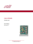
CANSPIDER
User’s Manual
Hardware Revision 1.0B
User’s Manual
CANSPIDER
Active 4-Port CAN Hub
User’s Manual
REAL TIME DEVICES FINLAND OY
LEPOLANTIE 14
FIN-00660 HELSINKI
FINLAND
Phone: (+358) 9 346 4538
FAX: (+358) 9 346 4539
E-Mail
[email protected]
Website
www.rtdfinland.fi
CANSPIDER
2
RTD Finland Oy
User’s Manual
Revision History
10/04/1998
24/07/1998
16/03/1999
10/07/2001
Initial release
Step B hardware update
Small corrections made
Contents updated and formatted
Notice: We have attempted to verify all information in this manual as of the publication
date. Information in this manual may change without prior notice from RTD Finland Oy.
Published by
Real Time Devices Finland Oy
Lepolantie 14
FIN-00660 Helsinki
Finland
Copyright 1997-2001 Real Time Devices Finland Oy
All rights reserved
Printed in Finland
PC/XT, PC/AT are registered trademarks of IBM Corporation.
PC/104 is a registered trademark of PC/104 Consortium.
The Real Time Devices Logo is a registered trademark of Real Time Devices.
CANSPIDER is a trademark of RTD Finland Oy.
utilityModule is a trademark of Real Time Devices.
Windows, Windows NT, Windows 95 are trademarks of Microsoft.
VersaLink is a Trademark of Hewlett Packard.
All other trademarks appearing in this document are the property of their respective owners.
CANSPIDER
3
RTD Finland Oy
User’s Manual
Table of Contents
CHAPTER 1 INTRODUCTION........................................................................................ 5
Features................................................................................................................................................ 5
CHAPTER 2 CONNECTING THE CANSPIDER ............................................................. 6
Jumpers................................................................................................................................................ 6
Fiberoptic CAN Ports ........................................................................................................................... 8
CHAPTER 3 RETURN POLICY AND WARRANTY...................................................... 12
Return Policy...................................................................................................................................... 12
Limited Warranty................................................................................................................................ 13
CANSPIDER
4
RTD Finland Oy
User’s Manual
Chapter 1 INTRODUCTION
This manual provides information on the CANSPIDER active CAN bus hub. The
CANSPIDER can connect up to four fiberoptic ECAN527-2 PC/104 CAN bus interface
boards together. Other CAN bus devices may be connected to the galvanically isolated
twisted pair CAN port. This structure enables flexible expansion of CAN Spiders as well
as connection of twisted pair CAN devices to your network.
ECAN527-2
The ECAN527-2 is a single channel CAN bus interface module for PC/104 systems. This
board features the Intel CAN 2.0B compliant controller AN82527. The fiberoptic interface
is integrated onboard. Fiberoptic network cables can be directly wired to the ECAN527-2
and the CANSPIDER using the Hewlett Packard “VersaLink” cabling system.
Features
The following are major features of the CANSPIDER:
•
Fiberoptic CAN Ports with data rates up to 1 Mbps
•
One galvanically isolated twisted pair CAN port for system expansion
•
Onboard bus termination resistors
•
Onboard power supply with 8-40 VDC input range
•
Power outputs include +5V and isolated +5V
Connectors
Connectors provided are:
•
•
•
•
•
J11:
J3:
J2:
J5:
FIBER:
Power supply input 8-40V
+5V output from onboard power converter
Isolated +5V output from onboard DC/DC converter
10-pin Header for twisted pair CAN bus
4 Fiberoptic CAN ports with 2 transceivers each
General Specifications
•
•
•
•
CANSPIDER
Dimensions:
Weight (mass):
Physical:
Operating conditions:
Standard temperature:
Extended temperature:
Relative humidity:
Storage temperature:
5
3.8 x 3.9 x 0.6" (97 x 100 x 16 mm)
To be defined
2-layer PCB
0 to + 70 degrees C
-40 to + 85 degrees C
0 to 95%, non-condensing
-55 to +85 degrees C
RTD Finland Oy
User’s Manual
Chapter 2
CONNECTING THE CAN SPIDER
The following sections contain information on configuring the CANSPIDER.
Please read this entire section before attempting to use the module!
Jumpers
One jumper configures the following function:
•
CAN Bus Termination Jumper
Jumper options
The CANSPIDERis delivered from the factory configured according to the following
table.
Jumper
X9
Default Jumper Settings
Setting
Function
1-2
CAN bus terminated
For most applications, you will not have to change this setting. If you do, refer to the
following pages for details on correct settings.
CANSPIDER
6
RTD Finland Oy
User’s Manual
Locations
The figure below shows jumper locations.
Descriptions
The following table describes the function of this jumper:
Jumper
Use
Connects or Disconnects a 120 Ohm onboard CAN-bus
X9
termination resistor
1-2:
No bus expansion, CAN bus terminated
with 2 termination resistors onboard
Disconnected: Only one onboard 120 Ohm resistor
terminates the bus
Default: 1-2,
Bus termination connected
The CANSPIDER converts four fiberoptic CAN ports into a galvanic CAN bus. The
galvanic CAN bus is implemented with traces on the Spider board. Therefore bus
termination must be performed to make the network operate correctly. If no other CAN
devices are connected, the CANSPIDER and the onboard CAN bus must be terminated
at both ends of the physical bus. To do that you should close jumper X9.
CANSPIDER
7
RTD Finland Oy
User’s Manual
Fiberoptic CAN Ports
Four fiberoptic RTD CAN-boards can be connected to the RTD CANSPIDER. Each port
consists of a separate transmitter and receiver. The ECAN527-2 board also features a
separate fiberoptic transmit and receive transceiver.
To connect your ECAN527-2 to the CANSPIDER you should use the correct fiberoptic
cable. Failure to do so may result in unreliable or degraded network operation. We
recommend you to purchase the SK-CAN-FIBER starter kit when you are evaluating and
testing your system. The correct ready-made duplex cables can be purchased from RTD.
The factory recommended Hewlett Packard cable part number is HFBR-END-XXX
(where XXX is the cable length). The SK-CAN-FIBER includes 2 of the HFBR-END-002
(2 meter cable length).
The ECAN527-2 as well as the CANSPIDER uses the following transceivers:
Transmitter:
HFBR-1522
Receiver:
HFBR-2522
These parts support a 1Mbd data rate with cable lengths up to 45 meters. For more
detailed information on the fiberoptic performance please visit the Hewlett Packard
website at:
www.hp.com/HP-COMP/fiber/hfbr0501.htm
NOTE:
CANSPIDER
The fiberoptic transceivers are classified as IEC 825-1 Accessible Emission
Limit (AEL) Class 1 based upon the current proposed draft scheduled to go
to effect on January 1, 1997. AEL Class 1 LED devices are considered eye
safe. For more information please contact your local Hewlett Packard sales
representative.
8
RTD Finland Oy
User’s Manual
Twisted Pair CAN Port
The CANSPIDERmodule features a 10-pin header connector that carries the galvanically
isolated CAN bus interface. The interface is wired according to the ISO11898 /2/
definition. The power output in this connector is derived from the isolating DC/DC
converter. The output is +5V DC and it is short circuit protected.
The pinout of this connector (facing the pins) is shown below:
9
7
5
3
1
I_GND
N.C.
I_GND
BUS_L
N.C.
N.C.
I_+5V
N.C.
BUS_H
I_GND
10
8
6
4
2
In this connector specification I_GND is the isolated ground and the I_+5V is the isolated
power output. When making connections in twisted pair CAN networks you connect the
BUS_H and BUS_L terminals together for all the nodes and terminate the bus at both
ends with a 120 Ohm termination resistor.
Connection Procedure
Please follow these steps when you set up your system:
•
Set up your ECAN527-2 CAN interface boards in their PC/104 systems
•
Connect the duplex fiberoptic cables to the ECAN527-2 modules: blue plug to blue
socket and gray plug to gray socket.
•
Connect the duplex fiberoptic cables to the CANSPIDER module ports: blue plug to
blue socket and gray plug to gray socket.
•
Make sure your power supply for the CANSPIDER provides a voltage between 8-30
VDC
•
Power off the power supply that should power the CANSPIDER
•
Wire the power supply to the CANSPIDER.
•
Power up your ECAN527-2 systems as well as your CANSPIDER
•
If no smoke appears you are in good shape. Now run the diagnostic software on your
host CAN computers and make sure everything is working.
CAUTION: The power supply of the CANSPIDER is overvoltage protected with a 39V
Zener diode as well as reverse polarity protected with a Schottky diode.
These devices are designed to protect the CANSPIDER power supply from
transients and spikes in automotive and industrial installations. They are not
designed to withstand wrong polarity or overvoltage for indefinite periods of
time.
CANSPIDER
9
RTD Finland Oy
User’s Manual
Example system setup
The figure below illustrates a possible system configuration. Use the twisted pair CAN
port to expand with multiple CANSPIDERS as well as other sensors of actuators with a
CAN interface.
CANSPIDER
10
RTD Finland Oy
User’s Manual
Power Supply Connections
The Real Time Devices CANSPIDER is designed to operate in standalone mode
removed from the main computer. This module has an integrated wide input range
power supply unit. The power supply system of the CANSPIDER consists of two DC/DC
converters in series.
The first DC/DC converter is a non-isolated step-down DC/DC converter that converts a
wide input range of 8-40V to +5V. The total output power of this stage is 25W, i.e. 5A of
current. This output power rating can not be reached without adding a heat sink to the
TO-220 DC/DC converter chip. The output of the step down converter is located at
terminal block J3 next to the input terminal block. This output can be used to power other
5V devices in the system.
The output of the step down converter is connected to an isolated monolithic regulated
DC/DC converter. This power unit supplies the onboard circuitry. It also provides power
out from the CAN bus header as well as the screw terminal block J2 that is located close
by. This DC/DC converter has a maximum output power of 3W. You may load this
converter with 1.5W max. The output of this converter is short circuit protected to
improve reliability.
Note:
CANSPIDER
Power wiring to the CANSPIDER must be sufficiently heavy to supply
needed current without excessive voltage drop, or erratic operation or no
startup may occur.
11
RTD Finland Oy
User’s Manual
Chapter 3 RETURN
POLICY AND WARRANTY
Return Policy
If the module requires repair, you may return it to us by following the procedure listed
below:
Caution:
Failure to follow this return procedure will almost always delay repair! Please
help us expedite your repair by following this procedure.
1) Read the limited warranty, which follows.
2) Contact the factory and request a Returned Merchandise Authorization (RMA)
number.
3) On a sheet of paper, write the name, phone number, and fax number of a technically
competent person who can answer questions about the problem.
4) On the paper, write a detailed description of the problem with the product. Answer the
following questions:
• Did the product ever work in your application?
• What other devices were connected to the product?
• How was power supplied to the product?
• What features did and did not work?
• What was being done when the product failed?
• What were environmental conditions when the product failed?
5) Indicate the method we should use to ship the product back to you.
We will return warranty repairs by UPS Ground at our expense.
Warranty repairs may be returned by a faster service at your expense.
Non-warranty repairs will be returned by UPS Ground or the method you
select, and will be billed to you.
6) Clearly specify the address to which we should return the product when repaired.
•
•
•
7) Enclose the paper with the product being returned.
8) Carefully package the product to be returned using anti-static packaging! We will not
be responsible for products damaged in transit for repair.
7) Write the RMA number on the outside of the package.
8) Ship the package to:
Real Time Devices Finland Oy
Lepolantie 14
FIN-0060 Helsinki
FINLAND
CANSPIDER
12
RTD Finland Oy
User’s Manual
Limited Warranty
Real Time Devices warrants the hardware and software products it manufactures and
produces to be free from defects in materials and workmanship for one year following
the date of shipment from REAL TIME DEVICES. This warranty is limited to the original
purchaser of product and is not transferable.
During the one year warranty period, REAL TIME DEVICES will repair or replace, at its
option, any defective products or parts at no additional charge, provided that the product
is returned, shipping prepaid, to REAL TIME DEVICES. All replaced parts and products
become the property of REAL TIME DEVICES. Before returning any product for repair,
customers are required to contact the factory for an RMA number.
THIS LIMITED WARRANTY DOES NOT EXTEND TO ANY PRODUCTS WHICH HAVE
BEEN DAMAGED AS A RESULT OF ACCIDENT, MISUSE, ABUSE (such as: use of
incorrect input voltages, improper or insufficient ventilation, failure to follow the
operating instructions that are provided by REAL TIME DEVICES, "acts of God" or other
contingencies beyond the control of REAL TIME DEVICES), OR AS A RESULT OF
SERVICE OR MODIFICATION BY ANYONE OTHER THAN REAL TIME DEVICES.
EXCEPT AS EXPRESSLY SET FORTH ABOVE, NO OTHER WARRANTIES ARE
EXPRESSED OR IMPLIED, INCLUDING, BUT NOT LIMITED TO, ANY IMPLIED
WARRANTIES OF MERCHANTABILITY AND FITNESS FOR A PARTICULAR
PURPOSE, AND REAL TIME DEVICES EXPRESSLY DISCLAIMS ALL WARRANTIES
NOT STATED HEREIN. ALL IMPLIED WARRANTIES, INCLUDING IMPLIED
WARRANTIES FOR MECHANTABILITY AND FITNESS FOR A PARTICULAR
PURPOSE, ARE LIMITED TO THE DURATION OF THIS WARRANTY. IN THE EVENT
THE PRODUCT IS NOT FREE FROM DEFECTS AS WARRANTED ABOVE, THE
PURCHASER'S SOLE REMEDY SHALL BE REPAIR OR REPLACEMENT AS
PROVIDED ABOVE. UNDER NO CIRCUMSTANCES WILL REAL TIME DEVICES BE
LIABLE TO THE PURCHASER OR ANY USER FOR ANY DAMAGES, INCLUDING
ANY INCIDENTAL OR CONSEQUENTIAL DAMAGES, EXPENSES, LOST PROFITS,
LOST SAVINGS, OR OTHER DAMAGES ARISING OUT OF THE USE OR INABILITY
TO USE THE PRODUCT.
SOME STATES DO NOT ALLOW THE EXCLUSION OR LIMITATION OF INCIDENTAL
OR CONSEQUENTIAL DAMAGES FOR CONSUMER PRODUCTS, AND SOME
STATES DO NOT ALLOW LIMITATIONS ON HOW LONG AN IMPLIED WARRANTY
LASTS, SO THE ABOVE LIMITATIONS OR EXCLUSIONS MAY NOT APPLY TO YOU.
THIS WARRANTY GIVES YOU SPECIFIC LEGAL RIGHTS, AND YOU MAY ALSO
HAVE OTHER RIGHTS, WHICH VARY FROM STATE TO STATE.
CANSPIDER
13
RTD Finland Oy