1
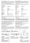
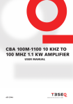
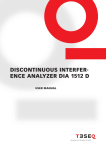
Input-/Output-Box
IOB 4000
User Manual
Coupling
Decoupling Network (CDN)
Input-/Output-Box
CDN type
IOB
4000
User Manual
CDN M116
CDN M210B, M216, M016
CDN M310B, M316, M316B, M325
CDN M416, M416-3LN, M425, M425-3LN
CDN M516, M525
Contens
1.
1.1.
1.2.
1.3.
2.
2.1.
2.2.
2.3.
2.4.
3.
3.1.
3.2.
3.2.1.
3.2.2.
3.2.3.
3.3.
4.
4.1.
4.2.
4.2.1.
4.2.2.
4.3.
4.4.
4.5.
4.6.
5.
5.1.
5.2.
6.
6.1.
6.2.
6.2.1.
6.3.
6.3.1.
6.3.2.
6.4.
6.4.1.
6.4.2.
6.4.2.1.
6.4.2.2.
6.4.2.3.
6.4.3.
6.4.4.
6.5.
7.
7.1.
7.1.1.
7.1.2.
7.2.
7.2.1.
7.2.2.
7.2.3.
Safety advice......................................................................................................................... 5
General....................................................................................................................................................... 5
Installation.................................................................................................................................................. 5
Applicable safety standards...................................................................................................................... 5
Unpacking, storage and transport........................................................................................ 6
General....................................................................................................................................................... 6
Storage and transport............................................................................................................................... 6
Unpacking.................................................................................................................................................. 6
Scope of delivery....................................................................................................................................... 6
General description and application . .................................................................................. 7
General....................................................................................................................................................... 7
Accessories................................................................................................................................................ 8
Fiber optical cable..................................................................................................................................... 8
USB to serial/optical converter: USO 4013............................................................................................... 8
Battery charger.......................................................................................................................................... 8
Application areas....................................................................................................................................... 8
Design.................................................................................................................................... 9
Mechanical dimensions............................................................................................................................ 9
Digital inputs.............................................................................................................................................. 9
TTL.............................................................................................................................................................. 9
0 … 24 V..................................................................................................................................................... 9
Analogue inputs......................................................................................................................................... 9
Optical Input............................................................................................................................................. 10
Digital outputs.......................................................................................................................................... 10
Optical RS232 interface........................................................................................................................... 10
Commissioning.................................................................................................................... 10
Power supply........................................................................................................................................... 10
Connection to the PC.............................................................................................................................. 11
Test software IO-Test.......................................................................................................... 12
Overview.................................................................................................................................................. 12
General settings....................................................................................................................................... 13
COM port settings.................................................................................................................................... 13
Measuring interval................................................................................................................................... 13
Device ID.................................................................................................................................................. 14
Battery status........................................................................................................................................... 14
Inputs....................................................................................................................................................... 14
Optical input............................................................................................................................................. 14
TTL inputs................................................................................................................................................. 15
Capture positive edge............................................................................................................................. 15
Capture negative edge............................................................................................................................ 16
No latch function .................................................................................................................................... 16
Digital inputs 24V..................................................................................................................................... 17
Analogue inputs....................................................................................................................................... 17
Outputs ................................................................................................................................................... 17
Commands........................................................................................................................... 18
System commands.................................................................................................................................. 18
CMD_WAKE_UP – 0x57........................................................................................................................... 18
CMD_GET_IDN? – 0x58............................................................................................................................ 18
Get commands........................................................................................................................................ 18
CMD_GET_DIG_INPUTS? – 0x61.............................................................................................................. 18
CMD_GET_BATT_LEVEL? - 0x62.............................................................................................................. 19
CMD_GET_ANAx_LEVEL?........................................................................................................................ 20
85-254700 E01
3
4
7.3.
7.3.1.
7.3.2.
7.4.
7.4.1.
7.4.2.
7.4.3.
7.4.4.
8.
8.1.
8.2.
8.4.
8.5.
8.3.
9.
9.1.
9.2.
10.
Set and clear commands........................................................................................................................ 20
CMD_SET_TTL_OUT_x............................................................................................................................. 20
CMD_CLEAR_TTL_OUT_x........................................................................................................................ 20
Configuration commands . ..................................................................................................................... 21
CMD_IN_xx_LATCH_POS......................................................................................................................... 21
CMD_IN_xxLATCH_NEG........................................................................................................................... 21
CMD_IN_xx_LATCH_OFF......................................................................................................................... 22
Commands overview.............................................................................................................................. 22
Technical Specification........................................................................................................ 24
Electrical specification . .......................................................................................................................... 24
EUT monitoring connections................................................................................................................... 24
Mechanical specification......................................................................................................................... 25
Environment conditions.......................................................................................................................... 25
Specification of the USB to serial/optical converter: USO 4013............................................................ 25
Maintenance........................................................................................................................ 26
General..................................................................................................................................................... 26
Cleaning................................................................................................................................................... 26
Disposal................................................................................................................................ 26
IOB 4000
1.Safety advice
These operating instructions form an integral part of the equipment and must be available to the operating
personnel at all times. All the safety instructions and advice notes are to be observed. Neither Teseq GmbH
nor any of the subsidiary sales organizations or the manufacturer can accept any responsibility for personal,
material or consequential injury, loss or damage that results from improper use of the equipment and accessories.
WARNING:
Improper or careless handling can be fatal!
Use of the IOB 4000 is restricted to authorized and trained specialists
1.1. General
■■ Use of the IOB 4000 is restricted to authorized and trained specialists
■■ Check the condition of the EUT at regular intervals and avoid any contact to live parts of the setup. In the
fault case dangerous voltage may be transferred from the EUT to the IOB 4000.
■■ Operate the equipment only in dry surroundings.
■■ The construction of the unit renders it unsuitable for use in an explosive atmosphere.
■■ Only approved accessory items, connectors, adapters, etc. are to be used to ensure safe operation.
1.2.Installation
Operate the IOB 4000 only in dry surroundings. Allow any condensation that occurs to evaporate before putting
the instrument into operation. Do not exceed the permissible ambient temperature, humidity or altitude.
Connections are not protected by fuses inside the IOB 4000. Avoid any over load with adequate arrangements.
1.3.Applicable safety standards
Development and manufacture of the instrument complies with ISO 9001. The product conforms with the
requirements of the EMC Directive 2004/108/EC and Low Voltage Directive (LVD) 2006/95/EC based on DIN
EN 61326-1:2006 and DIN EN 61010-1:2001.
85-254700 E01
5
6
2.Unpacking, storage and transport
2.1. General
■■ Throw nothing away!
Packaging either:
■■ Return to the relevant sales outlet
■■ Dispose of in an environmentally friendly manner
Packaging materials Cardboard
■■ Carton:
■■ Padding:
CFC-free polystyrene foam
■■ Plastic bags: Polyethylene
Avoid the risk of condensation occurring! If a large temperature difference has been experienced, allow time
for the temperature to stabilize. This may take several hours
.
2.2.Storage and transport
■■ Do not stack, either packaged or out of the packing.
■■ Do not up-end, arrows on the packaging must always point upwards.
■■ Protect from dampness, heat, cold and rain
■■ Do not throw
■■ Do not sit or stand on the instrument and packaging.
2.3.Unpacking
■■ Is the packaging damaged? ■■ Are all the packages present and correct?
■■ Are the instrument or accessories damaged? ■■ Are the contents of the package complete? ■■ Keep the instruction manual with the instrument.
■■ Keep the packaging.
2.4.Scope of delivery
■■ IOB 4000
■■ USO 4013
■■ 10 m fiber optical cable
■■ Charger
■■ 4 batteries type: Mignon (AA)
■■ User manual
■■ CD with driver and software
■■ Suitcase
IOB 4000
If YES
If NO
If YES
If NO
☎
☎
☎
☎
transportation company
transportation company
transportation company
sales outlet
3.General description and application
3.1. General
The Input / Output Box, in short IOB 4000, is an ideal addition for electromagnetic immunity test systems. With
its 12 digital inputs, as many signals on one test item can be monitored. In doing so, there are two available
voltage ranges; 0 V … 24 V and TTL level. There are 4 analogue inputs available which have a voltage range of
0 V … 24 V for monitoring analogue voltage values.
The monitoring of light sources such as, for example operating indicator lamps, can be realized with the
optical input.
The IOB 4000 can be integrated in the test house software. The instruction set is provided and own applications can be written. The communication is performed via an optical RS232 interface which enables faultless
access to the IOB 4000 in an immunity test setup.
All functions of the IOB 4000 can be tested with the included software “IO-Test“. The communications
port can be selected, the BOX can be woken up, the number of measurements per second can be set, the
serial number can be read and the battery status can be seen. All hardware inputs and outputs of the IOB 4000
are also in the window.
The box consists of a robust metal case optimized for EMC. This is due to the intended use as interface box
for monitoring signals for EMC measurements. The power supply is made using batteries in order to guarantee
operation independent of mains power.
IOB 4000
10 m fiber
USO 4013
optical cable
Figure 1: IOB 4000 with connected fiber optic cable and USO 4013
85-254700 E01
USB-Connection
(to PC)
7
8
3.2.Accessories
The appropriate accessories are supplied in order to be able to optimally use the IOB 4000.
3.2.1. Fiber optical cable
This is a 10 metres long plastic fiber optic cable. The length of the cable is matched to the circuit of the optotransmitter in the IOB 4000.
3.2.2. USB to serial/optical converter: USO 4013
Using this converter, it is possible to convert the optical RS232 signals into electrical ones and receive them
via USB cable connection with the PC. The installation of a driver is required for this.
3.2.3. Battery charger
The supplied battery charger must be used to charge the batteries.
3.3.Application areas
The IOB 4000 is intended to be located with the test item in a corresponding test environment (e.g. screened
room, anechoic chamber, TEM cell or reverberation chamber). It is also used to monitor relevant electrical and
optical parameters or indicators of a test item. The transfer to the control PC is performed using the optical
RS232 interface whereby an electromagnetic coupling is avoided.
In doing so, four analogue signals in the range 0 V … 24 V and twelve digital signals can be monitored. Eight
of these are with TTL level and four in the range of 0 V … 24 V. The latch function facilitates the detection
of sporadic level drop-outs or level peaks because the digital inputs can be triggered by the remote control
software on the rising or the falling edge.
Battery compartment
Figure 2: IOB 4000 front view
IOB 4000
Digital inputs
Analogue inputs
9
ON/OFF switch
LED
Fiber
input
optic
TTL input
TTL output
Optical
RS232
Figure 3: IOB 4000 rear view
4.Design
4.1. Mechanical dimensions
Die The IOB 4000 has a rectangular case with a length of 160 mm, a width of 80 mm and a height of 60 mm
(without attachments). It is made of a robust aluminium alloy.
There are 8 BNC sockets (Figure 2) on the front panel. These are four analogue inputs and four digital inputs.
On the rear panel (Figure 3), there are two D-SUB sockets, the optical input, the optical RS232 port and the
On/Off switch with operating indicator lamp.
The battery compartment is on the left of the front panel and consists of two tubes which each hold two
Mignon batteries (Figure 4).
4.2.Digital inputs
4.2.1. TTL
There is a D-SUB socket which combines 8 digital inputs on the rear panel of the IOB 4000 (Figure 3). The inputs
are designed for TTL levels and can be configured using the remote control software. The monitor events can
be triggered of rising or falling edge. Furthermore, these inputs can also be operated unlatched where the
status is returned on the respective line in each case (Chapter 6.3.2).
4.2.2. 0 … 24 V
The same description as for TTL applies to these digital inputs. However, these inputs are accessible using BNC sockets on the front panel of the IOB 4000 (Figure 2) and are compatible with a level of
0 V … 24 V. Due to the downstream optocouplers, the switching threshold here is also approx. 3 V and the
inputs are also galvanically decoupled.
4.3.Analogue inputs
The analogue inputs are accessible using four BNC sockets on the front panel of the IOB 4000 (Figure 2). The
voltage range is 0 V … 24 V. The threshold frequencies of the analogue inputs are limited by the µ controller
and the number of inputs to be monitored. A total of 5 channels of the ADC are used. One internal and four
external channels. A cut-off frequency of 6 kHz for the four analogue inputs is produced due to the internal
processing, the five individual channels and the external circuit of the µ controller. 85-254700 E01
10
4.4.Optical Input
The optical input can be used for monitoring indicator lamps. An application would be the monitoring of the
indicator lamp of a device to be tested as a gauge of a possible malfunction. The light can be conducted to
the optical receiver via a 1 mm plastic fiber optic cable. If light is received by the input, it returns a HIGH and
if the input is dark, a LOW is returned (Chapter 6.3.1).
4.5.Digital outputs
The digital outputs are combined in a D-SUB socket on the rear panel of the IOB 4000 (Figure 3). There are
eight freely configurable lines with Low Level TTL level available.
4.6.Optical RS232 interface
Both the connections for the transmitter and receiver are located on the rear panel of the IOB 4000. The
opto-transmitters have a theoretical output of 1 MBd for a maximum cable length of 24 metres.
The interface is optimized to it function with 10 metres of fiber optic cable. The USO 4013 is also available.
The COM port requires the following settings:
■■
■■
■■
■■
■■
115200 bits per second
8 data bits
no parity
1 stop bit
no flow control
5.Commissioning
5.1. Power supply
The power supply of the IOB 4000 is 4.8 V. It is provided by four Mignon 1.2 V batteries. The batteries must be
charged completely before first use. The current battery condition can be queried using the remote control
software. The internal channel of the ADC mentioned in section 4.3 is available for this. The battery status bit
(OK/WARNING) is also transmitted with every digital return value which the IOB 4000 sends.
A special circuit puts the IOB 4000 into a sleep mode in case of inactivity which helps to extend the battery
operating time. The current consumption in this state is approx. 6 mA. The current consumption increases
to approx. 26 mA in operation. In order to guarantee reliable operation and protect the batteries against
complete discharge, the IOB 4000 is switched off below approx. 4.2 V. A warning is transmitted previously
using the battery status bit.
Battery compartment
Figure 4: IOB 4000 side view
IOB 4000
The battery compartment consists of two tubes, each holding two batteries. These are located on the left
front panel of the IOB 4000. These tubes can be opened with a suitable object (coin, large screwdriver). Ensure
the correct polarity when inserting the batteries.
The IOB 4000 is switched on and off with the Power On / Off switch. The operating status indicator LED shows
the battery status. The following properties of the operating status indicator lamp can be read from Table 1:
Switch position
Operating status
Status
Switch Off: LED Off
IOB 4000 is switched off.
Normal operation
Switch On: LED On (dimmed)
IOB 4000 is ready for operation
Normal operation
Switch On: LED flashes (2.5 Hz)
IOB 4000 is ready for operation, indicates criti- Warning!
cal battery charge status
Replace batteries
Switch On: LED Off
IOB 4000 is in sleep mode. This condition occurs Normal operation
if no commands have been received via the Energy saving mode
optical RS232 port for 30 seconds.
Table 1: Properties of the operating status indicator lamp
After switching on the IOB 4000, the battery voltage is checked first so that the following power-on sequence
must be observed:
■■ switch from “Off” to “On”
■■ LED flashes for one second (charging the capacitors)
■■ LED lights without flashing
■■ If no communication is present, the LED goes out after 30 seconds. The IOB 4000 goes into sleep mode
in order to conserve the batteries.
If the batteries in the switched-on state are already in a critical condition, the LED remains in the flashing
mode. The batteries must be charged. If the battery charge status is not sufficient, the LED goes out again
immediately or possibly shows no reaction at all.
5.2.Connection to the PC
There is an optical RS232 port available for remote control of the IOB 4000. The connection to the control PC
is thus made using the supplied fiber optic cable which results in a favorable electrical decoupling between
IOB 4000 and control PC. Thus a possible coupling of the interference factors on the communication cable
is also prevented.
Furthermore, the USB to serial/optic converter USO 4013 is required in order to convert the light pulses into
electrical ones. Figure 1 shows how the IOB 4000 is connected.
In order to be able to use the USB to serial/optic converter US0 4013, its driver must be installed on the
control PC. In the normal case, the IOB 4000 is now ready for operation and can be tested using the IO Test
software.
85-254700 E01
11
12
6.Test software IO-Test
6.1. Overview
All functions of the IOB 4000 can be tested with the test program. The communications
port can be selected, the BOX can be woken up, the number of measurements per second can be set, the
serial number can be read and the battery status can be seen. All hardware inputs and outputs of the IOB
4000 are also in the window. These can be operated or read using the corresponding sections of the program
interface.
The individual sections are described in detail in the following sections.
Figure 5: Main Window
IOB 4000
6.2.General settings
6.2.1. COM port settings
13
Figure 6: COM settings
The corresponding COM port which is located on the USO 4013 is configured in this section. This can best
be ascertained in the Device Manager of the control PC. For example, COM 6 is selected in Figure 6. The
parameters of the serial connection are shown next to the port. These are used as information for how the
serial port of the control PC must be configured. See section 4.6.
The “Init / Wake up” button is located on the far right in Figure 6. The IOB 4000 can be initialized with this after
starting the test program. Scenario:
■■
■■
■■
■■
IOB 4000 is switched on
IO test is started, but no Device ID and battery voltage are displayed
The data exchange between IOB 4000 and control PC is started by pressing the “Init / Wake
Device ID and battery voltage are displayed
The same applies if the communication connection between IOB 4000 and control PC has been interrupted
although both sides are switched on. In this case, the displays can assume nonsensical values or simply hang.
After establishing the connection again, the IOB 4000 must be woken up with the “Init / Wake up” button. The
displays show the correct values again afterwards.
6.3.Measuring interval
Figure 7: COM settings
It can be configured in this section how often the inputs of the IOB 4000 should be polled. The measuring
interval can be set between 1 ms and 10,000 ms.
85-254700 E01
14
6.3.1.
Device ID
Figure 8: Device identifier
Figure 8 shows the field in which the Teseq device identifier appears. It is the name and the serial number of
the device. This field also gives information about the firmware version running in the device. In this case, it
is thus the IOB 4000 No. 23 which firmware V1.0 is running on.
6.3.2.
Battery status
Figure 9: Battery status
The charge level of the batteries is shown in the status field as a bar with percentage display and as a numeric
value with absolute voltage level. The LED on the far right in Figure 9 lights if the voltage level reaches a critical
value. This LED is controlled by the same status bit which also controls the flashing of the operating status
indicator lamp on the IOB 4000 (see Table 1).
6.4.Inputs
6.4.1. Optical input
Figure 10: Optical input
Figure 10 shows the section of the program interface in which the optical input can be polled. The display
differentiates between light and dark.
IOB 4000
6.4.2.
TTL inputs
15
Figure 11: TTL inputs display
The digital inputs with TTL level can be configured in this section. As shown in Figure 11, there are 8 such
inputs available which are accessible using the D-SUB socket on the rear panel of the IOB 4000 (Figure 3). As
well as the respective number of the input, its status is shown as a word and as an icon (LED). The selection
menus on the right edge of the section are used for the configuration of the different modes.
There are three different modes available which should be explained in the following.
6.4.2.1. Capture positive edge
1
Messintervall
0
1
2
3
4
5
t/s
Figure 12: Input signal, digital input, relevant edges
If the digital input is configured on the positive edge, the response to the question “Was a positive edge present
in this measuring interval?” is made in digital form after each measuring interval. The input is HIGH if a positive
edge is detected. The input is LOW if no positive edge is detected. See Table 2.
85-254700 E01
16
6.4.2.2. Capture negative edge
1
Messintervall
0
1
2
3
4
t/s
5
Figure 13: Input signal, digital input, relevant edges
If the digital input is configured on the negative edge, the response to the question “Was a negative edge
present in this measuring interval?” is made in digital form after each measuring interval. The input is HIGH if
a negative edge is detected. The input is LOW if no negative edge is detected. See Table 2.
6.4.2.3. No latch function
1
Messintervall
0
1
2
3
4
t/s
5
Figure 14: Input signal, digital input, measuring points for deactivated latch function
If the latch functions are dispensed with, exactly the state of the measurement signal at the time of the
measurement is registered. These points are marked with red circles in Figure 14. Therefore it does not matter
what happened within the measuring interval. Only the status at the time of the measurement counts for the
result in each case.
The Table 2 below summarizes which results can be obtained with the three different configurations of the
digital inputs. Thereby, these are based for example on the signal course in the Figures 12 to 14.
Configuration
Measuring points
1
2
3
4
5
Positiv glitch
High
Low
High
High
Low
Negativ glitch
Low
High
High
High
Low
Latch Off
High
Low
Low
High
High
Table 2: Behavior of the digital inputs depending on the latch function
IOB 4000
6.4.3.
Digital inputs 24V
17
Figure 15: Digital inputs display
The same applies to these four inputs as described in section 6.3.2. Only the input level can be up to 24 V here
as can be seen in Figure 15 at the top left.
6.4.4.
Analogue inputs
Figure 16: Analogue inputs display
Figure 16 shows the section of four analogue inputs. The input range is given with 0 V to 24 V. The displayed
voltage values are measured at the end of the measurement interval. For more details see figure 14.
6.5.Outputs
Figure 17: LVTTL outputs controller
The low voltage (LV) TTL outputs can be configured in this section. These are accessible at the D-SUB socket
on the rear panel of the IOB 4000 (Figure 3).
85-254700 E01
18
7. Commands
General a command consists of a byte. A requests answer consists of two bytes. Command names have been
used in this chapter should be seen as proposals.
7.1. System commands
7.1.1. CMD_WAKE_UP – 0x57
This command is important and needed to move the IOB 4000 from the Sleep Mode to the operating condition. The IOB 4000 must be woken up by the command 0x57 in case no command has been send during the
last 30 s.
Important!
The IOB 4000 must be woken up after 30 s idling.
7.1.2. CMD_GET_IDN? – 0x58
The device ID can be read out with the command 0x58. Included in the string are the name of the device, the
serial number and the firmware version. See figure 8. This command offers a way to check the communication
after the Sleep Mode has been terminated.
7.2.Get commands
7.2.1. CMD_GET_DIG_INPUTS? – 0x61
The structure of the return value of this command is given in table 3. The 8 TTL inputs are related to the bits
of the LOW Byte. This means:
■■
■■
■■
Bit 0 …
Bit 7 --> Input 1
--> Input 8
The HIGH Byte combines 24 V digital inputs, optical input and the bit of the battery status. This means:
■■
■■
■■
■■
■■
■■
Bit 0 …
Bit 3 Bit 4 Bit 5 and 6 Bit 7 IOB 4000
--> Input 1
--> Input 4
--> Optical input
--> Reserve
--> Battery status (LOW --> OK, HIGH --> WARNING)
HIGH Byte
7
6
LOW Byte
5
Batt.
19
4
3
2
1
0
7
6
5
4
3
2
1
0
LWL
D4_24V
D3_24V
D2_24V
D1_24V
D8_5V
D7_5V
D6_5V
D5_5V
D4_5V
D3_5V
D2_5V
D1_5V
Table 3: Structure of the return value for the digital inputs
Example 1: Request of all digital inputs
The status of the digital inputs can be requested through the command 0x61. The result is similar to table 4
under following conditions: TTL inputs as given in figure 11, 24 V digital inputs are related to figure 15, dark
optical input and battery status ok. The return value is 0x155.
HIGH Byte
LOW Byte
7
6
5
4
3
2
1
0
7
6
5
4
3
2
1
0
0
0
0
0
0
0
0
1
0
1
0
1
0
1
0
1
Table 4: Structure of the return value for example 1
7.2.2.
CMD_GET_BATT_LEVEL? - 0x62
This command has the HEX value of 0x62. The return value is similar to table 5 and represents the battery
voltage in Millivolts.
HIGH Byte
LOW Byte
7
6
5
4
3
2
1
0
7
6
5
4
3
2
1
0
MSB
x
x
x
x
x
x
x
x
x
x
x
x
x
x
LSB
Table 5: Structure of the return value for the analogue channels
Example 2: Request of the battery voltage
The return value of the command 0x62 is similar to table 6 under following conditions: The battery voltage
is given with 5.032 V which is converted to the HEX with 0x13A8 (decimal value: 5032). The voltage value is
directly given in [mV].
HIGH Byte
LOW Byte
7
6
5
4
3
2
1
0
7
6
5
4
3
2
1
0
0
0
0
1
0
0
1
1
1
0
1
0
1
0
0
0
Table 6: Structure of the return value for example 2
85-254700 E01
20
7.2.3. CMD_GET_ANAx_LEVEL?
The commands are used to request the four analogue channels.
■■ Channel 1: CMD_GET_ANA0_LEVEL --> 0x63
■■ Channel 2: CMD_GET_ANA1_LEVEL --> 0x64
■■ Channel 3: CMD_GET_ANA2_LEVEL --> 0x65
■■ Channel 4: CMD_GET_ANA3_LEVEL --> 0x66
The return value is given direct in [mV].
Example 3: Request of the analogue input voltage
This example has been made to request the analogue channels 1 and 2. The voltage values are 8.03 V on
channel 1 and 4.193 V on channel 2 (see figure 16). The command 0x63 gets the return of 0x1F5E which is 8030
as decimal value. The command 0x64 delivers a return value of 0x1061 which is 4193 as decimal value. (see
table 7). The return value is directly given in [mV].
HIGH Byte
LOW Byte
7
6
5
4
3
2
1
0
7
6
5
4
3
2
1
0
0
0
0
1
0
0
0
0
0
1
1
0
0
0
0
1
Table 7: Structure of the return value for example 3
7.3.Set and clear commands
7.3.1. CMD_SET_TTL_OUT_x
The commands are needed to set the TTL outputs to High. There exists 8 channels with following commands:
■■ Channel 1: CMD_SET_TTL_OUT_1 --> 0x6B
■■ Channel 2: CMD_SET_TTL_OUT_2 --> 0x6C
■■ Channel 3: CMD_SET_TTL_OUT_3 --> 0x6D
■■ Channel 4: CMD_SET_TTL_OUT_4 --> 0x6E
■■ Channel 5: CMD_SET_TTL_OUT_5 --> 0x6F
■■ Channel 6: CMD_SET_TTL_OUT_6 --> 0x70
■■ Channel 7: CMD_SET_TTL_OUT_7 --> 0x71
■■ Channel 8: CMD_SET_TTL_OUT_8 --> 0x72
Example 4: Set TTL outputs
To get the state of the outputs as given in figure 17, one has to sent must be required to sent 0x6B, 0x6D, 0x6F,
0x71 via the serial interface to the IOB 4000.
7.3.2. CMD_CLEAR_TTL_OUT_x
The settings given in chapter 7.3.1 can be canceled with the commands as following. The corresponding
channel will be switched to LOW.
■■ Channel 1: CMD_CLEAR_TTL_OUT_1 --> 0x73
■■ Channel 2: CMD_CLEAR_TTL_OUT_2 --> 0x74
■■ Channel 3: CMD_CLEAR_TTL_OUT_3 --> 0x75
■■ Channel 4: CMD_CLEAR_TTL_OUT_4 --> 0x76
■■ Channel 5: CMD_CLEAR_TTL_OUT_5 --> 0x77
■■ Channel 6: CMD_CLEAR_TTL_OUT_6 --> 0x78
■■ Channel 7: CMD_CLEAR_TTL_OUT_7 --> 0x79
■■ Channel 8: CMD_CLEAR_TTL_OUT_8 --> 0x7A
IOB 4000
Example 5: Reset of the TTL outputs
The commands 0x73, 0x75, 0x77, 0x79 allow to reset the settings of example 4.
7.4.Configuration commands
The latch function can be activated with the configuration commands for all digital inputs. The events could be
latched to the positive or negative edge. The settings have direct influence on the return values. See chapter
6.3.2. Predefined is the state: „Latch off“, which is used also after switching on the IOB 4000. The configuration
of a channel lasts as long the unit is either switched off or the commend has been reset. It does not matter
how many requests have been made to the selected channel.
7.4.1. CMD_IN_xx_LATCH_POS
Following commands have been made to latch the positive edge. See figure 12.
Examples for the TTL inputs:
■■ Channel 1: CMD_IN_01_LATCH_POS --> 0x30
■■ Channel 2: CMD_IN_02_LATCH_POS --> 0x33
■■ Channel 3: CMD_IN_03_LATCH_POS --> 0x36
■■ Channel 4: CMD_IN_04_LATCH_POS --> 0x39
■■ Channel 5: CMD_IN_05_LATCH_POS --> 0x3C
■■ Channel 6: CMD_IN_06_LATCH_POS --> 0x3F
■■ Channel 7: CMD_IN_07_LATCH_POS --> 0x42
■■ Channel 8: CMD_IN_08_LATCH_POS --> 0x45
Examples for the 24 V inputs:
■■ Channel 1: CMD_IN_09_LATCH_POS --> 0x48
■■ Channel 2: CMD_IN_10_LATCH_POS --> 0x4B
■■ Channel 3: CMD_IN_11_LATCH_POS --> 0x4E
■■ Channel 4: CMD_IN_12_LATCH_POS --> 0x51
7.4.2. CMD_IN_xxLATCH_NEG
Following commands have been made to latch the negative edge. See figure 13.
Examples for the TTL inputs:
■■ Channel 1: CMD_IN_01_LATCH_NEG --> 0x31
■■ Channel 2: CMD_IN_02_LATCH_NEG --> 0x34
■■ Channel 3: CMD_IN_03_LATCH_NEG --> 0x37
■■ Channel 4: CMD_IN_04_LATCH_NEG --> 0x3A
■■ Channel 5: CMD_IN_05_LATCH_NEG --> 0x3D
■■ Channel 6: CMD_IN_06_LATCH_NEG --> 0x40
■■ Channel 7: CMD_IN_07_LATCH_NEG --> 0x43
■■ Channel 8: CMD_IN_08_LATCH_NEG --> 0x46
Examples for the 24 V inputs:
■■ Channel 1: CMD_IN_09_LATCH_NEG --> 0x49
■■ Channel 2: CMD_IN_10_LATCH_NEG --> 0x4C
■■ Channel 3: CMD_IN_11_LATCH_NEG --> 0x4F
■■ Channel 4: CMD_IN_12_LATCH_NEG --> 0x52
85-254700 E01
21
22
7.4.3. CMD_IN_xx_LATCH_OFF
Following commands have been made to switch off the latch function. See figure 14. The state: „Latch off“ is
selected always after switching on the IOB 4000 for all digital inputs.
Examples for the TTL inputs:
■■ Channel 1: CMD_IN_01_LATCH_OFF --> 0x32
■■ Channel 2: CMD_IN_02_LATCH_OFF --> 0x35
■■ Channel 3: CMD_IN_03_LATCH_OFF --> 0x38
■■ Channel 4: CMD_IN_04_LATCH_OFF --> 0x3B
■■ Channel 5: CMD_IN_05_LATCH_OFF --> 0x3E
■■ Channel 6: CMD_IN_06_LATCH_OFF --> 0x41
■■ Channel 7: CMD_IN_07_LATCH_OFF --> 0x44
■■ Channel 8: CMD_IN_08_LATCH_OFF --> 0x47
Examples for the 24 V inputs:
■■ Channel 1: CMD_IN_09_LATCH_OFF --> 0x4A
■■ Channel 2: CMD_IN_10_LATCH_OFF --> 0x4D
■■ Channel 3: CMD_IN_11_LATCH_OFF --> 0x50
■■ Channel 4: CMD_IN_12_LATCH_OFF --> 0x53
7.4.4. Commands overview
// ~~~ commands for config. digital inputs ~~~ //
TTL-INPUTS
CMD_IN_01_LATCH_POS --> 0x30 CMD_IN_01_LATCH_NEG --> 0x31 CMD_IN_01_LATCH_OFF --> 0x32 CMD_IN_02_LATCH_POS --> 0x33 CMD_IN_02_LATCH_NEG --> 0x34 CMD_IN_02_LATCH_OFF --> 0x35 CMD_IN_03_LATCH_POS --> 0x36 CMD_IN_03_LATCH_NEG --> 0x37 CMD_IN_03_LATCH_OFF --> 0x38 CMD_IN_04_LATCH_POS --> 0x39 CMD_IN_04_LATCH_NEG --> 0x3A CMD_IN_04_LATCH_OFF --> 0x3B CMD_IN_05_LATCH_POS --> 0x3C CMD_IN_05_LATCH_NEG --> 0x3D CMD_IN_05_LATCH_OFF --> 0x3E CMD_IN_06_LATCH_POS --> 0x3F CMD_IN_06_LATCH_NEG --> 0x40 CMD_IN_06_LATCH_OFF --> 0x41 CMD_IN_07_LATCH_POS --> 0x42 CMD_IN_07_LATCH_NEG --> 0x43 CMD_IN_07_LATCH_OFF --> 0x44 CMD_IN_08_LATCH_POS --> 0x45 CMD_IN_08_LATCH_NEG --> 0x46 CMD_IN_08_LATCH_OFF --> 0x47 IOB 4000
(ASCII-Key 0)
(ASCII-Key 1)
(ASCII-Key 2)
(ASCII-Key 3)
(ASCII-Key 4)
(ASCII-Key 5)
(ASCII-Key 6)
(ASCII-Key 7)
(ASCII-Key 8)
(ASCII-Key 9)
(ASCII-Key :)
(ASCII-Key ;)
(ASCII-Key <)
(ASCII-Key =)
(ASCII-Key >)
(ASCII-Key ?)
(ASCII-Key @)
(ASCII-Key A)
(ASCII-Key B)
(ASCII-Key C)
(ASCII-Key D)
(ASCII-Key E)
(ASCII-Key F)
(ASCII-Key G)
24-V-INPUTS
23
CMD_IN_09_LATCH_POS --> 0x48 CMD_IN_09_LATCH_NEG --> 0x49 CMD_IN_09_LATCH_OFF --> 0x4A CMD_IN_10_LATCH_POS --> 0x4B CMD_IN_10_LATCH_NEG --> 0x4C CMD_IN_10_LATCH_OFF --> 0x4D CMD_IN_11_LATCH_POS --> 0x4E CMD_IN_11_LATCH_NEG --> 0x4F CMD_IN_11_LATCH_OFF --> 0x50 CMD_IN_12_LATCH_POS --> 0x51 CMD_IN_12_LATCH_NEG --> 0x52 CMD_IN_12_LATCH_OFF --> 0x53 (ASCII-Key H)
(ASCII-Key I)
(ASCII-Key J)
(ASCII-Key K)
(ASCII-Key L)
(ASCII-Key M)
(ASCII-Key N)
(ASCII-Key O)
(ASCII-Key P)
(ASCII-Key Q)
(ASCII-Key R)
(ASCII-Key S)
// ~~~ get commands ~~~ //
CMD_GET_DIG_INPUTS
CMD_GET_BATT_LEVEL
CMD_GET_ANA0_LEVEL
CMD_GET_ANA1_LEVEL
CMD_GET_ANA2_LEVEL
CMD_GET_ANA3_LEVEL
--> 0x61 --> 0x62 --> 0x63 --> 0x64 --> 0x65 --> 0x66 (ASCII-Key a)
(ASCII-Key b)
(ASCII-Key c)
(ASCII-Key d)
(ASCII-Key e)
(ASCII-Key f)
// ~~~ set and clear commands ~~~ //
CMD_SET_TTL_OUT_1 CMD_SET_TTL_OUT_2 CMD_SET_TTL_OUT_3 CMD_SET_TTL_OUT_4 CMD_SET_TTL_OUT_5 CMD_SET_TTL_OUT_6 CMD_SET_TTL_OUT_7 CMD_SET_TTL_OUT_8 CMD_CLEAR_TTL_OUT_1 CMD_CLEAR_TTL_OUT_2 CMD_CLEAR_TTL_OUT_3 CMD_CLEAR_TTL_OUT_4 CMD_CLEAR_TTL_OUT_5 CMD_CLEAR_TTL_OUT_6 CMD_CLEAR_TTL_OUT_7 CMD_CLEAR_TTL_OUT_8 --> 0x6B --> 0x6C --> 0x6D --> 0x6E --> 0x6F --> 0x70 --> 0x71 --> 0x72 --> 0x73 --> 0x74 --> 0x75 --> 0x76 --> 0x77 --> 0x78 --> 0x79 --> 0x7A (ASCII-Key k)
(ASCII-Key l)
(ASCII-Key m)
(ASCII-Key n)
(ASCII-Key o)
(ASCII-Key p)
(ASCII-Key q)
(ASCII-Key r)
(ASCII-Key s)
(ASCII-Key t)
(ASCII-Key u)
(ASCII-Key v)
(ASCII-Key w)
(ASCII-Key x)
(ASCII-Key y)
(ASCII-Key z)
// ~~~ system commands ~~~ //
CMD_WAKE_UP
CMD_GET_IDN
85-254700 E01
--> 0x57 --> 0x58 (ASCII-Key W)
(ASCII-Key X)
24
8.Technical Specification
8.1. Electrical specification
Supply:
Charging conditions:
Operating time (fully charged set of batteries):
Current consumption (sleep mode):
Current consumption (operation):
Power switch:
Communication interface to USO 4013:
Connection:
Distance:
4 x 1,2V Mignon (AA) rechargeable batteries, exchange-
able, extended battery charger
LED, display within software and deep-discharge protec-
tion
approx. 1 week with 8 h active operating per day and 16 h sleep mode
approx. 6 mA
approx. 26 mA
hardware switch
opt. RS232
2x HFBR0501 socket for 1 mm fiber optic cable 10 m (>10 m on request)
8.2.EUT monitoring connections
Analogue input
Quantity:
4
Connector:
4x BNC sockets
Input range:
0 V ... 24 V
Cut-off frequency:
fg = 6 kHz
Resolution:
10 Bit
Input resistance:
Rein = 25 kΩ
Digital input
Quantity:
4 Connector:
4x BNC sockets
Input range:
0 V to 24 V
Threshold level: approx. 3 V
Latch:
Latch to trigger on pos. and neg. edge
Digital input
Quantity:
8
Connector:
D-SUB socket, 9 pins
Input range:
TTL level
Latch:
Latch to trigger on pos. and neg. edge
Digital output
Quantity:
8
Connector:
D-SUB socket, 9 pins
Output range:
LVTTL (3.3 V)
Configuration:
programmable by user
Optical input
Connector:
HFBR0501 socket for 1 mm fiber optic cable
IOB 4000
8.4.Mechanical specification
Dimensions of the chassis (L x W x H):
Dimensions over all (L x W x H):
Dimensions of the suitcase (L x W x H):
Weight:
Weight (complete in the suitcase):
25
160 mm x 80 mm x 60 mm
160 mm x 113 mm x 60 mm
450 mm x 360 mm x 135 mm
approx. 0.8 kg
approx. 3 kg
8.5.Environment conditions
Classification:
Operating temperature:
Relative humidity:
Indoor use only
+5°C to +40 °C
up to 80% (no moisture condensation)
8.3.Specification of the USB to serial/optical converter: USO 4013
Supply:
Current consumption:
Indicator lamps:
Interface to IOB 4000:
Connector:
Communication interface:
Connector:
Communication interface to PC:
Connector:
Cable length:
Dimensions of the chassis (L x W x H):
Weight:
85-254700 E01
via USB
approx. 50 mA
LED blue: RX, LED orange: TX
optical
2 x HFBR0501 socket for 1 mm fiber optic cable
RS232
D-SUB plug, 9 pins
USB
USB A type
approx. 1.7 m
57 mm x 70 mm x 24 mm
approx. 133 g
26
9. Maintenance
9.1. General
The IOB 4000 including the accessories need no special maintenance. The maintenance is limited to the
cleaning of the contacts. The life time of the connectors is limited because of the contact durability. Teseq
can replace the worn out connectors.
No modifications are to be carried out on the IOB 4000 and accessories by the user.
9.2.Cleaning
The cleaning shall be done with dry cloth. If a wed cleaning would become necessary, make sure that no
humidity will enter inside of the unit and clean the instrument housing with a damp cloth using a little mild,
non-abrasive household cleanser if necessary.
Chemicals must not be used for cleaning purposes
10. Disposal
The unit is constructed that it can be dismantled right down to the component level.
IOB 4000
27
Headquarters
Teseq AG
4542 Luterbach, Switzerland
T + 41 32 681 40 40
F + 41 32 681 40 48
sales @ teseq.com
www.teseq.com
Manufacturer
Teseq GmbH
12623 Berlin, Germany
Landsberger Str. 255
T + 49 30 5659 8835
F + 49 30 5659 8834
desales @ teseq.com
China
Teseq Company Limited
T + 86 10 8460 8080
F + 86 10 8460 8078
chinasales @ teseq.com
France
Teseq Sarl
T + 33 1 39 47 42 21
F + 33 1 39 47 40 92
francesales @ teseq.com
Germany
Teseq GmbH
T + 49 30 5659 8835
F + 49 30 5659 8834
desales @ teseq.com
Japan
Teseq K.K.
T +81 3 5725 9460
F +81 3 5725 9461
japansales @t eseq.com
Singapore
Teseq Pte Ltd.
T + 65 6846 2488
F + 65 6841 4282
singaporesales @ teseq.com
Switzerland
Teseq AG
T + 41 32 681 40 50
F + 41 32 681 40 48
sales @ teseq.com
UK
Teseq Ltd.
T + 44 845 074 0660
F + 44 845 074 0656
uksales @ teseq.com
USA
Teseq Inc.
T + 1 732 417 0501
F + 1 732 417 0511
Toll free +1 888 417 0501
usasales @ teseq.com
To find your local partner within
Teseq’s global network, please go to
www.teseq.com
Teseq is an ISO-registered company. Its products
are designed and manufactured under the strict
quality requirement of the ISO 9001.
© April 2009 Teseq
Specifications subject to change without notice. All
trademarks recognized.
This document has been carefully checked.
However, Teseq does not assume any liability for
errors or inaccuracies.