1
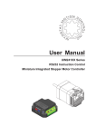
User Manual
UIM241XX Series
RS232 Instruction Control
Miniature Integrated Stepper Motor Controller
UIM24102/04/08
Please pay attention to the following before using the UIROBOT products:
1. UIROBOT products meet the specification contained in their particular Data Sheet.
2. UIROBOT will only work with the customer who respects the Intellectual Property (IP) protection.
3. Attempts to break UIROBOT’s IP protection feature may be a violation of the local Copyright Acts. If such acts lead to unauthorized
access to UIROBOT’s IP work, UIROBOT has a right to sue for relief under that Act.
Information contained in this publication regarding controller applications and the like is provided only for your convenience
and may be superseded by updates. It is your responsibility to ensure that your application meets with your specifications.
UIROBOT MAKES NO REPRESENTATIONS OR WARRANTIES OF ANY KIND WHETHER EXPRESS OR IMPLIED,
WRITTEN OR ORAL, STATUTORY OR OTHERWISE, RELATED TO THE INFORMATION, INCLUDING BUT NOT LIMITED
TO ITS CONDITION, QUALITY, PERFORMANCE, MERCHANTABILITY OR FITNESS FOR PURPOSE. UIROBOT
disclaims all liability arising from this information and its use. Use of UIROBOT products in life support and/or safety
applications is entirely at the buyer’s risk, and the buyer agrees to defend, indemnify and hold harmless UIROBOT from any
and all damages, claims, suits, or expenses resulting from such use. No licenses are conveyed, implicitly or otherwise, under
any UIROBOT intellectual property rights.
[Trade Mark/ Layout-design/Patent]
The UIROBOT name and logo are registered trademarks of UIROBOT Ltd. in the P.R. China and other countries.
UIROBOT’s UIM24XXX series Step Motor Controllers, UIM25XX series CAN-RS232 Converter and their layout designs are
patent protected.
[UIM241XX Ordering Information]
In order to serve you quicker and better, please provide the product number in following format.
UIM241XX PART NUMBERING SYSTEM
UIM
2 4 1
Category
Series
Motor
Control
RS232
Control
L
0 2
T
-
MS
E / IE = External / Internal Encoder ClosedLoop
Optional
Control
Connector
Peak Current
M
= Advanced Motion Control
S
= Sendor Control
T = Screw Terminal; P = Plug / Socket;
02 = 2A;
04 = 4A;
08 = 8A
Maximum
Supply Voltage L = 35V;
C =40V;
H = 50V
Note:
1) Peak current is decided by max. supply voltage (See in Table 0-1).
2) Default control connector is T (screw terminal), if not selected.
Table 0-1 Correspondence between Max. Supply Voltage and Peak Current
Voltage
L(35V)
C(40V)
H(50V)
2A
√
√*
√*
4A
×
√
√*
8A
×
√
√*
Current
*: Custom made, please contact with salesmans before purchase.
Examples:
UIM241L02P; UIM241C04T-MS; UIM241C08P-IE;
Page 2
M4120130828EN
UI Robot Technology Co. Ltd.
UIM241XX Miniature Integrated Stepper Motor Controller
Examples of Control Connector options:
Screw Terminal
UI Robot Technology Co. Ltd.
Rectangular Plug / Socket
M4120130828EN
Page 3
UIM24102/04/08
UIM24102 / 04 / 08
RS232 Instruction Control
Miniature Integrated Stepper Motor Contrller
Miniature Integral Design
Embedded DSP Microprocessor
− Miniature size 42.3mm*42.3mm*16.5mm
− Firmware DSP, 64bits calculating precision
− Fit onto motors seamlessly
− Absolute position record / feedback, reset
by instruction or sensor
− Die-cast aluminum enclosure, improving
heat dissipation and durability
− Quadrature encoder based closed-loop
control
Motor Driving Characteristics
− Wide supply voltage range 12 ~ 40VDC
− Output
current
2/4/8A,
instruction
adjustable
− Full to 16th micro-step resolution
− Dual full H-bridge with PWM constant
current control
− Accurate micro-stepping and current control
Network Communication
− RS232 three-wire serial communication
− Max baud rate 57600 bps
− Advanced motion control,linear and nonlinear acceleration and deceleration, Scurve, PT/PVT displacement control
− 2 sensor input ports
− 8 programmable real-time event-based
change notifications
− 13 programmable actions triggered by 6
sensor events
− Simple instructions
− Intelligent control, intuitive and faulttolerating
GENERAL DESCRIPTION
UIM24102 / UIM24104 / UIM24108 are miniature stepper motor controllers with RS232
interface. UIM241 controllers can be mounted onto NEMA17/23/34/42 series stepper
motor through adapting flanges. User device can command these controllers through
RS232 protocol using ASCII coded instructions. Instructions are simple, intuitive and
fault-tolerating. User is not required to have advanced knowledge on stepper motor
driving.
UIM241 can realize open-loop and encoder-based closed-loop control. UIM241’s
architecture includes communication system, basic motion control system, absolute
position counter, quadrature encoder interface and real-time event-based change
notification system. Furthermore, there are three optional modules can be installed per
customer
request:
Advanced
Motion
Control
Module
(linear/non-linear
acceleration/deceleration, S-curve PT/PVT displacement control), Encoder-based
Closed-loop Control Module and Sensor Input Control Module.
Embedded 64-bit calculating precision DSP controller guarantees the real-time
processing of the motion control and change notifications. Entire control process is
finished within 1 millisecond.
Enclosure is made of die-cast aluminum to provide a rugged durable protection and
improves the heat dissipation.
Page 4
M4120130828EN
UI Robot Technology Co. Ltd.
UIM241XX Miniature Integrated Stepper Motor Controller
TERMINAL DESCRIPTION
Figure0-1: Terminal Description
9
Motor
1
Terminals
A+
ABB+
V+
GND
RX
TX
GND
AG
S1
S2
RST
Control Termianals
Control Terminals
Terminal
Designator
No.
1
V+
Description
Supply voltage, 12 - 40VDC
2
GND
Supply voltage ground
3
RX
To the RX pin on user device
4
TX
To the TX pin on user device
5
GND
To signal ground on user device
6
AG
Analog ground for sensors
7
S1
Sensor input port 1
8
S2
Sensor input port 2
9
RST
Reset R232 baud rate to 9600
Motor Terminals
Terminal No.
Description
A+ / A-
Connect to the stepper motor phase A
B+ / B-
Connect to the stepper motor phase B
WARNING: Incorrect connection of phase winds will permanently damage the controller!
Resistance between leads of different phases is usually > 100KΩ. Resistance between
leads of the same phase is usually < 100Ω. It can simply measured by a multimeter.
WARNING: Except supply voltage port and motor terminal, voltage on port must be kept
between -0.3~5.3V. Otherwise, the controller will be damaged.
UI Robot Technology Co. Ltd.
M4120130828EN
Page 5
UIM24102/04/08
TYPICAL APPLICATION
Wiring of UIM241 is simple.
UIM241xx controllers use 3-wire RS232 interface to communicate with user devices.
Terminal 3 should be connected to the RX of user device; Terminal 4 should be
connected to the TX of user device; Terminal 5 should be connected to the GND of user
device. An example is provided in figure 0-2. User can use an existing RS232 cable or a
converted cable.
If the sensor inputs are used, make sure the signal are wired to the terminal 7 and/or
terminal 8, and the signal ground are wired to the terminal 6. Furthermore, please be
aware:
•
•
•
User is responsible for the power supply for sensors,
Voltage on terminal 7 and 8 must be kept between -0.3V and 5.3V
If using an external encoder, channel A should be connected to S1; channel B to S2;
GND to AG
Figure 0-2: Typical Application
Stepper motor
12 ~ 40VDC
1 V+
A+ A-
B-
B+
2 GND
3 RX
4 TX
UIM241XX
Controller
5 GND
6 AG
Sensor 1
7 S1
Sensor 2
8 S2
Terminal 9 is for resetting
Baud Rate (details in
chapter 3.4)
9 RST
PIN2 to RX (UIM terminal 3)
PIN3 to TX (UIM terminal 4)
PIN5 to GND (UIM terminal 5)
•
Page 6
M4120130828EN
UI Robot Technology Co. Ltd.
UIM241XX Miniature Integrated Stepper Motor Controller
INSTRUCTION SET SUMMARY
Network Communication
Instruction
BDRη;
Description
Set RS232 communication baud rate
Feedback Message
Header
ID
AA
BD
Page
51
Model Check
Instruction
MDL;
Description
Check the model of controller
Feedback Message
Header
ID
CC
DE
Page
68
Function Configuration
Instruction
ENAη;
ENAxFFFF;
ICFη;
ICF;
MCFη;
MCF;
SCFη;
SCF;
Description
Set enable time, boot time after η ms enable
Check enable time
Set initial configuration register
Check initial configuration register
Set master configuration register
Check master configuration register
Set sensor control configuration register η
Check sensor control configuration register
Feedback Message
Header
ID
AA
A0
AA
A0
AA
DA
AA
DA
AA
B0
AA
B0
AA
C0
AA
C0
Page
56
57
59
60
63
64
78
79
General Check
Instruction
;
FBK;
SFB;
Description
Check desired motor status
Check current motor status
Check sensor status
Feedback Message
Header
ID
AA
CC
CC
C1
Page
48
58
80
Motor Configuration
Instruction
ACRη;
ACR;
CURη;
ENA;
MCSη;
OFF;
Description
Set auto-current reduction ratio η
Check auto-current reduction ratio
Set output phase current η
Enable H-bridge circuit
Set micro-stepping resolution
Disable H-bridge circuit
UI Robot Technology Co. Ltd.
M4120130828EN
Feedback Message
Header
ID
AA
AA
AA
AA
AA
AA
BA
-
Page
49
50
54
55
65
73
Page 7
UIM24102/04/08
Motion Control
Instruction
BLCη;
BLC;
MACη;
MAC;
MDEη;
MDE;
MMDη
MMD;
MMSη;
MMS;
ORG;
ORGη;
POSη;
POS;
SPDη;
SPD;
STO;
STOη;
STPη;
STP;
Description
Set backlash compensation value η
Check backlash compensation value
Set acceleration rate η
Check acceleration rate
Set deceleration rate η
Check deceleration rate
Set maximum cessation speed η
Check maximum cessation speed
Set maximum starting speed η
Check maximum starting speed
Set zero/origin position
Reset the position to a given value η
Set desired position η (open-loop control)
Check current position
Set the desired speed η
Check current speed
Store motion control parameters
Bind motion control parameters to sensor edge
Set desired incremental displacement η
Check current incremental displacement
Feedback Message
Header
ID
AA
DE
AA
DE
AA
B1
AA
B1
AA
B2
AA
B2
AA
B4
AA
B4
AA
B3
AA
B3
AA
B7
AA
B7
AA
B7
CC
B0
AA
B5
CC
B2
AA
D1
AA
D1
AA
B6
CC
B3
Page
52
53
61
62
66
67
69
70
71
72
74
75
76
77
81
82
85
86
87
88
I/O Control
Instruction
STGη;
STG;
Page 8
Description
Set digital input sampling mode
Check digital input sampling mode
M4120130828EN
Feedback Message
Header
ID
AA
C9
AA
C9
Page
83
84
UI Robot Technology Co. Ltd.
UIM241XX Miniature Integrated Stepper Motor Controller
CHARACTERISTICS
Absolute Maximum Ratings
Supply voltage......................................................................................................................... 10V to 40V
Voltage on S1/S2 with respect to GND..................................................................-0.3V to +5.3V
Maximum output current sunk by S1/S2...................................................................................20 mA
Maximum output current sourced by S1/S2.............................................................................20 mA
Voltage on RX with respect to GND...................................................................................... -25V to +25V
Voltage on TX with respect to GND.............................................................................. -13.2V to +13.2V
Ambient temperature under bias....................................................................................... -20°C to +85°C
Storage temperature........................................................................................................ -50°C to +150°C
NOTE:Working under environment exceeding the above maximum value could result in permanent damage to controller.
Working under conditions at the maximum value is not recommended as operation at maximum value for extended period
may have negative effect on device reliability.
Electrical Characteristics(Ambient Temperature 25°C)
Supply Power Voltage
12V - 40VDC
Motor Output Current
Max 2A/4A/8A per phase (instruction adjustable)
Driving Mode
PWM constant current
Stepping Resolution
full-step, half-step, 1/4, 1/8 and 1/16 step
Communication (Ambient Temperature 25°C)
Protocol
RS232
Wiring method
3-wire: TX, RX, GND
Baud Rate
Max 57600 bps, instruction adjustable, Firmware reset to
9600
Environment Requirements
Cooling
Free air
Working environment
Avoid dust, oil mist and corrosive gases
Working temperature
-40 °C ~ 85°C
Humidity
<80%RH,no condensation, no frosting
Vibration
3G Max
Storage temperature
-50 °C ~ 150 °C
Size and Weight
Size
42.3mm x 42.3mm x 16.5mm
Weight
0.1 kg
UI Robot Technology Co. Ltd.
M4120130828EN
Page 9
UIM24102/04/08
CONTENTS
General Description..................................................................................................................................................... 4
Terminal DESCRIPTION .............................................................................................................................................. 5
Typical Application ...................................................................................................................................................... 6
Instruction set summary ............................................................................................................................................. 7
Characteristics ............................................................................................................................................................. 9
1.0
1.1
1.2
1.3
1.4
Overview ................................................................................................................................................... 12
Basic Control System ................................................................................................................................. 12
Advanced Motion Control Module............................................................................................................... 13
Sensor Input Control Module ...................................................................................................................... 13
Instructions and Interface ........................................................................................................................... 13
2.1
2.2
Instruction and Feedback Structure ....................................................................................................... 15
Instruction Structure ................................................................................................................................... 15
Macro Operator and Null Instruction ........................................................................................................... 15
3.1
3.2
3.3
3.4
RS232 communication ............................................................................................................................. 17
User Device RS232 Port Configuration ...................................................................................................... 17
Hand-Shaking ............................................................................................................................................. 17
Reset Baud Rate to Factory Default 9600 .................................................................................................. 17
Instruction List ............................................................................................................................................ 18
4.1
4.2
Real-time Change Notification................................................................................................................. 19
RTCN Structure .......................................................................................................................................... 19
Enable/Disable RTCN ................................................................................................................................ 19
5.1
5.2
5.3
5.4
5.5
initial and HARDware/Firmware Configuration ...................................................................................... 20
Initial Configuration Register (Firmware version: 1232 or higher) ............................................................... 20
Auto-enable ................................................................................................................................................ 21
User Program ............................................................................................................................................. 21
Master Configuration Register .................................................................................................................... 21
Instruction List ............................................................................................................................................ 22
6.1
6.2
6.3
6.4
Basic Control Instructions ....................................................................................................................... 23
General Introduction of Motion Control Modes ........................................................................................... 23
Basic Instruction Acknowledgment (ACK) .................................................................................................. 26
Motor Status Feedback Message ............................................................................................................... 27
Instruction List ............................................................................................................................................ 28
7.1
7.2
7.3
7.4
7.5
7.6
7.7
7.8
7.9
7.10
Advanced Motion Control ........................................................................................................................ 29
Linear Acceleration ..................................................................................................................................... 29
Linear Deceleration .................................................................................................................................... 29
Nonlinear Acceleration ............................................................................................................................... 29
Nonlinear Deceleration ............................................................................................................................... 31
S-curve Displacement Control .................................................................................................................... 32
Direction Control and Position Counter ...................................................................................................... 33
Backlash Compensation ............................................................................................................................. 34
Advanced Motion Control Instructions ........................................................................................................ 34
Enable/disable Advanced Motion Control Module (MCFG) ........................................................................ 35
Instruction List ............................................................................................................................................ 35
8.1
8.2
8.3
8.4
8.5
Sensor Input Control ................................................................................................................................ 37
Rising and Falling Edge.............................................................................................................................. 38
Analog Input and Thresholds ...................................................................................................................... 38
Digital Input Sampling Mode ....................................................................................................................... 39
Sensor Event, Action and Binding .............................................................................................................. 39
Introduction to Sensor Input Control Instructions ........................................................................................ 40
2.0
3.0
4.0
5.0
6.0
7.0
8.0
Page 10
M4120130828EN
UI Robot Technology Co. Ltd.
UIM241XX Miniature Integrated Stepper Motor Controller
8.6
8.7
8.8
8.9
8.10
Sensor Input Control Register S12CON ..................................................................................................... 41
Analog Threshold Control Register ATCONH & ATCONL .......................................................................... 41
Instruction List............................................................................................................................................. 43
Example of S12CON Configuration ............................................................................................................ 43
Example of ATCONH, ATCONL Configuration ........................................................................................... 44
9.1
9.2
9.3
1.
2.
3.
4.
5.
6.
7.
8.
9.
10.
11.
12.
13.
14.
15.
16.
17.
18.
19.
20.
21.
22.
23.
24.
25.
26.
27.
28.
29.
30.
31.
32.
33.
34.
35.
36.
37.
38.
39.
40.
41.
instruction ................................................................................................................................................. 45
Instruction Structure .................................................................................................................................... 45
Feedback Message Structure ..................................................................................................................... 45
Instruction Description ................................................................................................................................ 48
; Check desired motor status ...................................................................................................................... 48
ACRη Set auto-current reduction ratio ........................................................................................................ 49
ACR Check auto-current reduction ratio ..................................................................................................... 50
BDRη Set RS232 Baud Rate ...................................................................................................................... 51
BLCη Backlash compensation .................................................................................................................... 52
BLC Check backlash compensation ........................................................................................................... 53
CURη Motor Current Adjusting ................................................................................................................... 54
ENA H-Bridge Enable ................................................................................................................................. 55
ENAη Set enable time ................................................................................................................................ 56
ENAxFFFF Check enable time ................................................................................................................... 57
FBK Motor Status Feedback Inquiry ........................................................................................................... 58
ICFxη Initial Configuration Register Instruction ........................................................................................... 59
ICF Check Initial Configuration Register .................................................................................................... 60
MACη Set Acceleration Rate ...................................................................................................................... 61
MAC Check Current Acceleration Rate ...................................................................................................... 62
MCFη / MCFxη Master Configuration Register Instruction.......................................................................... 63
MCF Check Master Configuration Register ................................................................................................ 64
MCSη Setup Micro Stepping....................................................................................................................... 65
MDEη Set Deceleration Rate ...................................................................................................................... 66
MDE Check Current Deceleration Rate ...................................................................................................... 67
MDL Check Controller Model ...................................................................................................................... 68
MMDη Set Maximum Cessation Speed ...................................................................................................... 69
MMD Check current Maximum Cessation Speed ....................................................................................... 70
MMSη Set Maximum Starting Speed .......................................................................................................... 71
MMS Check current Maximum Starting Speed ........................................................................................... 72
OFF H- Bridge Disable ............................................................................................................................... 73
ORG Reset Position Counter ...................................................................................................................... 74
ORGη Reset Position Counter .................................................................................................................... 75
POSη Position Control ................................................................................................................................ 76
POS Check Current Position ...................................................................................................................... 77
SCFη / SCFxη Set Sensor Configuration .................................................................................................... 78
SCF Check the value of Sensor Configuration ........................................................................................... 79
SFB Check Sensor Data ............................................................................................................................. 80
SPDη Speed Adjusting ............................................................................................................................... 81
SPD Check Current Speed ......................................................................................................................... 82
STGxη Set Digital Input Sampling Mode .................................................................................................... 83
STG Check Digital Input Sampling Mode.................................................................................................... 84
STO EEPROM Store .................................................................................................................................. 85
STOη Parameter Banding........................................................................................................................... 86
STPη Displacement Control........................................................................................................................ 87
STP Check Displacement ........................................................................................................................... 88
9.0
UI Robot Technology Co. Ltd.
M4120130828EN
Page 11
UIM24102/04/08
1.0
OVERVIEW
UIM241 miniature integrated stepper motor controllers communicate with user device
using RS232 protocol. The user device controls UIM241 through ASCII coded
instructions. Communication baud rate can be changed through instruction
UIM241 has a size of 42.3mm*42.3mm*16.5mm and is designed to mount onto
NEMA17/23/34/42 stepper motors seamlessly. UIM24102 can provide 0.7-2A output
current; UIM24104 can provide 1.5-4A output current; UIM24108 can provide 3-8A output
current. Current value is adjustable within the range through instructions. Once set, the
value is stored in EEPROM. UIM241XX controller also has the function of high speed
current compensation to offset the effect of Back Electromotive Force (BEMF) of motor at
high speed and therefore to facilitate motor’s high-speed performance. UIM241XX series
of controllers work with 12 ~ 40VDC power supply.
UIM241XX can perform open-loop control. The control system comprises communication
system, basic motion control system, absolute position counter, and real-time eventbased change notification system. There are also two optional modules to be added on
customer request: Advanced Motion Module (linear/non-linear acceleration/deceleration,
S-curve PV/PVT displacement control), and Sensor Input control Module.
The embedded 64-bit calculation precision DSP controller guarantees the real-time
processing of the motion control and change notifications (similar to the interrupters of
CPU). Entire control process is finished within 1 millisecond.
1.1 Basic Control System
UIM241 controller’s basic control system comprises communication system, basic motion
control system, absolute position counter, and real-time event-based change notification
system.
Communication System
UIM241 controller communicates with user device using RS232 protocol. User device
controls the UIM241 controller through ASCII coded instructions. Communication baud
rate can be changed through instruction.
Basic Motion Control
UIM241 has a build-in basic motion control system. User device can control the following
basic motion parameters through instructions in real-time: direction, speed, angular
displacement, phase current, micro-stepping, and enable/disable the H-bridge, etc.
Speed input range is +/-65,000 pulses/sec, and displacement input range is +/2,000,000,000 pulses.
Absolute Position Counter
UIM241 has a hardware pulse counter. The counter can be reset either by user
instruction or automatically by the configurable sensor input event. Under most
conditions, through the advanced motion control, this counter can provide the absolute
position of the motor with enough accuracy. When the counter reaches zero position,
there could be automatically generated message feedback to the user device, given the
corresponding configuration through user instruction.
Furthermore, with the encoder-based closed-loop control module, the UIM241 can
perform self closed-loop control.
Page 12
M4120130828EN
UI Robot Technology Co. Ltd.
UIM241XX Miniature Integrated Stepper Motor Controller
Real-time Change Notification (RTCN)
Similar to CPU’s interrupters, UIM241XX can automatically generate certain messages
after predefined events and sends them to the user device. The time is less than 1
millisecond from the occurring of the event to the message being sent. Message transfer
time depends on the baud rate of the RS232 setup. The transfer time will be less than 1
millisecond if the baud rate is set to 57600. UIM241XX’s RTCN system supports 8
events: displacement control done absolution position reset; sensor 1/2 rising edge and
falling edge; analog input beyond upper threshold, analog input lower than lower
threshold, etc. All RTCNs can be enabled or disabled by instructions.
1.2 Advanced Motion Control Module
With advanced motion control module installed, UIM241XX controller can maintain linear
and non-linear acceleration/deceleration, S-curve displacement control, PT/PVT control,
auto direction control, etc. There are two ways to define acceleration/deceleration rate:
1.Value Mode: Input range: 1 ~ 65,000,000 PPS/Sec (pulse/sec2).
2.Period Mode: Input range: 1 ~60,000 milliseconds (time to fulfill the acceleration or
deceleration).
The input range of the displacement control is +/- 2 billion pulses (steps). In advanced
motion control mode, the actual direction is decided by module calculation. When
displacement is in place, there will be a RTCN (Instruction configurable). Advanced
motion control module can be disabled/enabled through user instruction.
1.3 Sensor Input Control Module
UIM241’s Sensor Input Control Module supports 2 channels of sensor input. They can
accept a TTL level input of 0~5V. There is 1 channel can be configured as analog input
(Precision: 12bit; Sample frequency: 50K; mean of 16 calculation; Update frequency:
1000Hz). User can configure the desired automatic action triggered by sensor status
change. There are 13 actions listed below that can be triggered by sensor event:
•
•
•
•
•
•
•
•
•
•
•
•
•
Start and run forwardly at preset-speed and acceleration
Start and run reversely at preset-speed and acceleration
Change direction and run at preset-speed and acceleration
Forword displacement control follow the preset motion parameters (speed,
displacement, acceleration)
Reverse displacement control follow the preset motion parameters (speed,
displacement, acceleration)
Direction-change displacement control follow the preset motion parameters (speed,
displacement, acceleration)
Decelerate at preset deceleration until stop
Emergency stop
Reset position and encoder counter
Reset position and encoder counter + Reverse displacement control follow the preset
motion parameters (speed, displacement, acceleration)
Reset position and encoder counter + Decelerate at preset deceleration until stop
Reset position and encoder counter + Emergency stop
Off
1.4 Instructions and Interface
Instructions for UIM241XX are simple, intuitive and fault-tolerating.
UI Robot Technology Co. Ltd.
M4120130828EN
Page 13
UIM24102/04/08
For example, in order to command a speed of 1000 steps/sec, the following instructions
are all valid: "SPD = 1000;", "SPD: 1000;", "SPD 1000;", "SPD1000;" or even
"SPD %?&%* 1000;".
In case that a wrong instruction is entered, the controller will return an ACK of error
message. Incorrect instructions will not be executed to prevent accidents.
UIROBOT provides free Microsoft Windows based VB / VC demo software and
corresponding source code to facilitate the quick start of user device side programming.
Page 14
M4120130828EN
UI Robot Technology Co. Ltd.
UIM241XX Miniature Integrated Stepper Motor Controller
2.0 INSTRUCTION AND FEEDBACK STRUCTURE
Once UIM241XX receives a message (instructions) from the user device, it will first ACK
back (repeat) the received instruction, and then execute the instruction. UIM241XX will
further send back a message to inform the user device of the completion of the
instruction. Before a new instruction is received, UIM241XX will keep current working
status (e.g. running, stop, etc.)
2.1 Instruction Structure
An instruction is a message sent from the user device to UIM241 to Comment certain
operation. Instructions of UIM241 follow the rules listed below:
INS η; or INSx η; or INS;
Instruction symbol INS comprises three letters with no space between them, and is not
case sensitive. If there is an x (INSx), then it means the value is hexadecimal. Value η
comprises set of numbers. Some instructions have no value, such as “SPD;”, “STP;” etc.
Each instruction must end with semicolon (;). Instruction without semicolon will cause
unpredictable results.
Feedback Message is the message sent to user device from UIM241 controller. The
maximum length of feedback messages is 13 bytes.
Feedback messages from UIM241 follow the structure below:
[Header] [Controller ID] [Message ID] [Data] [Terminator]
There are 3 kinds of headers: AA、CC and EE.
Controller ID the identification number of current controller in a network (also known as
Node ID). For UIM241, it is always 00..
Message ID denotes the property of the current message.
Data has a 7bits data structure. High is in front, and low is in the back. The 7bits data can
be translated into 16bits data through the shifting operation. One 16bit data takes three
7bits data to represent.
Terminator denotes the end of a feedback message. UIM241 controller utilizes “FF” or
“FE” as the terminator. If terminator is “FF”, it means there is no follow-up message; If
terminator is “FE”, it means there has follow-up messages.
Note: there are two types of feedback that has NO message ID: ACK message and Motor
Status feedback (controller’s response to FBK instruction). Other messages could have
NO data, such as some real-time change notification messages.
2.2 Macro Operator and Null Instruction
In practice, users will combine several instructions together and send them at once.
Normally, the user device will receive an ACK message on every instruction sent, these
message will cause pressure on CAN bus. Especially for those basic motion instructions
like SPD, DIR, MCS, which have the same ACK, sending a set of ACK is unnecessary.
For example:
CUR 20; MCS 16; SPD 5000; ENA;
The above instruction set will cause 4 ACK messages being transferred on the RS232
bus.
UI Robot Technology Co. Ltd.
M4120130828EN
Page 15
UIM24102/04/08
To facilitate the above situation, user can use the following method to send a set of
instructions:
{Instruction 1; Instruction 2; …Instruction N; }; (N<10)
For example:
{CUR 20; MCS 16; SPD 5000; ENA; };
UIM241XX will only send back 1 ACK on receiving the above message.
In the above example, “{” and “}” is called Macro Operator. Instructions between a pair
of macro operators will get no ACK message.
The semicolon at the end of the instruction set has no letter or number before it. That is
called Null Instruction. The only purpose of a Null Instruction is to tell the UIM242XX to
feedback all the inquired parameters of the basic motion control. (i.e. Enable/disable,
Current, Micro-stepping, Auto current reduction, Direction, Speed, and Displacement)
Actually, user can simply send the null instruction“;” alone to check the status of the
above parameters. If there is no null instruction “;” after the “}” in the above example,
there will be no ACK message at all.
Page 16
M4120130828EN
UI Robot Technology Co. Ltd.
UIM241XX Miniature Integrated Stepper Motor Controller
3.0
RS232 COMMUNICATION
UIM241xx controllers communicate and exchange information with user devices
throughRS232 serial protocol. The RS232 configuration of user device, the hand-shaking
methods and the instruction used to change the baud rate will be introduced in this
Chapter, along with the method to reset the baud rate to factory default.
3.1 User Device RS232 Port Configuration
To communicate with UIM241XX, user device needs to have following RS232 port
settings:
•
•
•
8 bits data
1 stop bit
None Parity
3.2 Hand-Shaking
Any out-of-box UIM241 controller has a factory default baud rate 9600. User can use the
9600 baud rate to connect to a new UIM241 controller.
If the baud rate has been changed, the new baud rate will be stored in the controller’s
non-volatile memory (EEPROM). New baud rate will take effect after the controller is
restarted.If user device knows the baud rate, it can start sending instructions without
hand-shaking
Hand-shaking is more used as a method to check the existence and firmware version of
the controller. Under following two situations the UIM241XX will issue a greeting
message:
1.
When UIM241XX is powered up.
2.
When UIM241XX receives following ASCII message: ABC; A message started with
AA, AB, AC at the user device implies a successful hand-shake.
A greeting Message from UIM241XX has the following structure:
Byte
1
2
3
4
5
6
7
Value
AA
AB
AC
18
01
CUR
Module
8
9
10
11
12
13
Firmware Version
00
00
FF
Where,
AA AB AC
denotes the greeting message
18 01
denotes the UIM241 controller.
[CUR]
denotes the maximum motor current the controller can provide.
[Module]
denotes the optional control modules the controller installed
[Firmware Version]
denotes the firmware version. Data is in 7 bits format.
Conversion from three 7bits message data to a 16bits integer is illustrated in figure 9-1.
3.3 Reset Baud Rate to Factory Default 9600
In case of forgotten the baud rate and cannot establish the connection, please take the
following steps to reset the baud rate to factory default of 9600.
UI Robot Technology Co. Ltd.
M4120130828EN
Page 17
UIM24102/04/08
1.
Reboot the controller.
2.
In 10 seconds, short the terminal 9 (figure 0-1) to analog ground (terminal 6) for 2
times, with intervals around 1 second.
3.
Each time, the LED on the controller will flash. If exceed 10 seconds, please restart
from step 1.
4.
If successful, the LED will turn off for one second and re-lit. That indicates the baud
rate has been changed to 9600 and ready to use.
5.
Use BDR instruction to change the baud rate to desired value.
3.4 Instruction List
The following table shows the instructions mentioned in this chapter, the detail of those
instructions is descriped at the end of the document.
Instruction
Description
BDRη;
Set the RS232 communication baud rate of
UIM241XX controller to η
51
MDL;
Check the Model, installed optional modules and
firmware version
55
Page 18
Page
M4120130828EN
UI Robot Technology Co. Ltd.
UIM241XX Miniature Integrated Stepper Motor Controller
4.0REAL-TIME CHANGE NOTIFICATION
UIM241 controllers support Real-time Change Notification (RTCN). Similar to interrupter
of CPU, a RTCN is generated and sent when a user predefined event happens. The
length of a RTCN is 4 bytes. The time from the occurrence of the event to the sending of
the RTCN is less than 1 millisecond. The time is decided by baud rate. The transfer time
is about 0.8ms (0.0008s) when the baud rate is 57600. Then, it takes only 1.5ms from an
event happening to a RTCN being received.
4.1 RTCN Structure
The structure of an RTCN message is shown below:
CC [Controller ID] [Message ID] FF
The RTCN system is able to response to the following events:
Table4-1: Real-time change notification events
No.
Event
Message ID
Description
1
falling edge of S1
A0
Voltage on S1: High >>>Low
2
rising edge of S1
A1
Voltage on S1: Low >>>High
3
falling edge of S2
A2
Voltage on S2: High >>>Low
4
rising edge of S2
A3
Voltage on S2: Low >>>High
5
exceed upper limits
A1*
Analog input > user preset upper limit
6
below lower limit
A0**
Analog input < user preset lower limit
7
displacement control complete
A8
The desired position is reached
8
zero position
A9
Position counter reaches/passes zero
Note:
* When S1 is configured as analog, A1 denotes event 9, otherwise A1 denotes event 2.
** When S1 is configured as analog, A0 denotes event 10, otherwise A0 denotes event 1.
4.2 Enable/Disable RTCN
Every RTCN can be enabled or disabled through user instruction. Enable/disable the
RTCN is achieved by the writing to the Master Configuration Register’s ORGIE bit
(MCFG<5>), STPIE bit (MCFG<4>), S2IE bit (MCFG<1>) and S1IE bit (MCFG<0>).
Please refer to section 5.4 for details.
Please note, to realize the sensor event control, user needs to further configure the
sensor control registers S12CON and ATCON. Please refer to Chapter 8.0 for details.
UI Robot Technology Co. Ltd.
M4120130828EN
Page 19
UIM24102/04/08
5.0 INITIAL AND HARDWARE/FIRMWARE
CONFIGURATION
UIM241’s hardware and firmware can be configured through user instructions. There are
4 configuration registers for UIM241: Initial Configuration Register, Master Configuration
Register, S12CON and Analog Threshold Register. In this chapter, only the Initial
Configuration Register and Mater Configuration Register are described. User can find
details about the other registers in their corresponding chapters.
5.1 Initial Configuration Register (Firmware version: 1232 or higher)
Initial configuration register is used to decide the initial status of the controllers after
power-on. Once configured, its value will be burned into the on-board EEPROM, and the
controller will auto reboot. Initial configuration register is a 16bits register with following
structure:
ICFG
Bit
Value
15
X
14
X
13
X
12
X
11
X
10
X
9
X
8
X
7
X
6
X
Bit15-4
Unimplemented. Read as 0.
Bit3
Elock, Lock when emergency events happen
5
X
4
X
3
2
1
0
Elock PROG CCW ENA
0=
After the sensor is emergency stop or power-off, the controller is unlock,
and can execute instructions.
1 = After the sensor is emergency stop or power-off, the controller is lock, and
receives no instruction. It needs to reboot the controller to unlock it.
Bit2
Execute user program after power-on (Future function)
Bit1
CCW, Adjust rotation direction (Figure 5-1)
0 = Set CW is positive; when turn CW, displacement counter accumulate;
otherwise, displacement counter decrease.
1 = Set anti-CW is positive; when turn anti-CW, displacement counter
accumulate; otherwise, displacement counter decrease.
Bit0
ENA, Auto-enable after powr-on
0 = Disable the function (Auto-enable after power-on)
1 = Enable the function, auto-enable the controller after the pre-set time
when power is on
Figure 5-1 Rotation Direction
Clockwise (CW)
Page 20
M4120130828EN
UI Robot Technology Co. Ltd.
UIM241XX Miniature Integrated Stepper Motor Controller
5.2 Auto-enable
Once ICFG.ENA is set to 1, UIM241 will auto enable the H-Bridge of motor after the
power is on for T ms, the interval time (T) can be set through instruction. For details of
the instruction, please refer to Chapter 9.
5.3 User Program
User can program on UIM241. Once ICFG.PROG is set to 1, UIM241 will execute user
program after the power is on. For details, please refer to “UIM Programming Manual”.
UIM241 still can execute user instructions when user program is running.
5.4 Master Configuration Register
Master Configuration Register is used to enable/disable the hardware/firmware
functions.Once configured, it will be effective immediately and its value will be burned
into the on-board EEPROM. The burning process will not affect any real-time
process.Master Configuration Register is a 16bits register with the following structure:
MCFG
bit
15
value ANE
14
13
12
11
10
9
8
7
6
CHS
QEI
X
QEM
CM
AM
DM
X
X
5
4
ORGIE STPIE
3
2
1
0
X
X
S2IE
S1IE
Bit15
ANE Enable / Disable Analog Input
0 = Disable the analog input, all sensor are set to digital input
1 = Enable the analog input, Port S1 can be set to analog input
Bit14
CHS Analog Input Channel
0 = Analog input on port S1
1 = Analog input on port S3 (only for UIM242)
Note: This bit is always 0, for UIM241, means only S1 can be configured as
Analog Input.
Bit13
QEI
Enable/Disable Quadrature Encoder Interface
0 = Disable Quadrature Encoder Interface
1 = Enable Quadrature Encoder Interface
Bit12
Unimplemented. Read as 0.
Bit11
QEM Enable/Disable Quadrature Encoder-based Closed-loop Control
Module
0 = Disable Quadrature Encoder-based Closed-loop Control Module
1 = Enable Quadrature Encoder-based Closed-loop Control Module
Bit10
CM
Advanced Motion Control Mode
0 = Disable advanced motion control module, use basic control mode
1 = Enable advanced motion control module
Bit9
AM
Acceleration Mode
0 = Value mode. Unit is pps/sec, or pulse/ (square second)
1 = Period mode. Unit is millisecond.
Bit8
DM
0 =
1 =
Bit7 - 6
Unimplemented. Read as 0.
Bit5
ORGIE
Origin (Zero) Position RTCN
0 = Disable the Origin (zero) position RTCN.
Deceleration Mode
Value mode. Unit is pps/sec, or pulse/ (square second)
Period mode. Unit is millisecond.
UI Robot Technology Co. Ltd.
M4120130828EN
Page 21
UIM24102/04/08
1 = Enable the Origin (zero) position RTCN. Once the value of pulsing counter
or encoder counter is zero, a message will be send to user device
automatically.
Bit4
STPIE Displacement Control (STP/POS/QEC) Completion RTCN
0 = Disable the displacement control completion RTCN.
1 = Enable the displacement control completion RTCN. Once the
displacementinstruction has been executed, a message will be send to
user device automatically.
Bit3 - 2
Unimplemented. Read as 0.
Bit1
S2IE S2 Status Change RTCN
0 = Disable sensor port 2 (S2) status change RTCN
1 = Enable S2 status change RTCN
Bit0
S1IE S1 Status Change RTCN
0 = Disable sensor port 1 (S1) status change RTCN
1 = Enable S1 status change RTCN
5.5 Instruction List
The following table shows the instructions mentioned in this chapter, the detail of those
instructions is descriped at the end of the document.
Instruction
ICFη;
ICF;
MCFη;
MCF;
Page 22
Description
Set initial configuration register
Check initial configuration register
Set master configuration register
Check master configuration register
M4120130828EN
Page
59
60
63
64
UI Robot Technology Co. Ltd.
UIM241XX Miniature Integrated Stepper Motor Controller
6.0BASIC CONTROL INSTRUCTIONS
UIM241 controllers support abundant motion control instructions. The instructions of
UIm241 are valid for both basic motion control (without acceleration/deceleration or Scurve displacement control) and advanced motion control (if the module is installed and
enabled). User can select either basic or advanced motion control by configuring the
Master Configuration Registration (MCFG).
In this Chapter, introduction to UIM241XX motion control modes is provided.
6.1 General Introduction of Motion Control Modes
There are three motion control modes for UIM241XX controller: Velocity Tracking (VT),
Position Tracking (PT) and Position Velocity Tracking (PVT).
Velocity Tracking (VT)
In the Velocity Tracking (VT) mode, UIM241XX controller controls the motor speed to
track desired speed.
Figure6-1 Velocity Tracking
Speed
Instruction “SPD 1000;” received at this point
1000
Current Speed
Basic motion control, speed rises without
acceleration process
Advanced motion control, linear/non-linear
acceleration
T (Time)
Speed
Current Speed
-1000
Instruction “SPD - 1000;” received at this point
Basic motion control, speed falls without
deceleration process
Advanced motion control, linear/non-linear
deceleration
T (Time)
Please note that: Sign (+/-) of the value of SPD instruction instructs the motion direction.
For example: both the instruction “SPD=1000;” and “SPD=+1000;” make motor run
forward at 1000pps. Meanwhile, the instruction “SPD= -1000;” can cause motor to run
backward at 1000pps.
If Advanced Motion Control Module is installed, speed control can be achieved through
linear or non-linear acceleration/deceleration. For details, please refer to Chapter 7.0
Advanced Motion Control. If Advanced Motion Control Module is not installed, once a
SPD instruction is received, motor speed will be set to desired speed.
Position Tracking (PT)
In the Position Tracking (PT) mode, UIM241 controller will keep motor running at a speed
close to the set value until it reaches the desired steps. After setting the desired speed,
user can enter desired positions or incremental displacement continuously or
discontinuously. UIM241 controller will make sure that the desired position is achieved
when trying to approach the desired speed to the greatest extent.
UI Robot Technology Co. Ltd.
M4120130828EN
Page 23
UIM24102/04/08
As shown in Figure 6-2, UIM241 controller operates in PT mode automatically on
receiving position instruction such as POS, STP until an instruction of “STP 0;” is given.
(STP is a displacement control instruction. Logically “STP 0;” means no displacement. It
is contradictory to send a displacement instruction of no displacement. Therefore,
UIM241 will take this instruction as a request to shift from PT mode to VT mode.)
In PT mode, the actual speed, direction and desired displacement are related to deviation
of actual displacement. When sign of desired speed and displacement deviation is
different, the actual direction is decided by displacement deviation, while actual speed is
set to absolute value of desired speed. Once deviation of desired and actual
displacement is too small, and the acceleration is also too small, then it may cause the
following situation: the motor has already reached the desired position, but it still has not
reached the desired speed.
Page 24
M4120130828EN
UI Robot Technology Co. Ltd.
UIM241XX Miniature Integrated Stepper Motor Controller
Figure6-2 Position Tracking Mode (without acceleration/deceleration)
Position
2000
1000
0
Receive OFF;
Receive STP0;
ReceivePOS 1000;
ReceiveSPD -2000;
Reach Position -2000
ReceivePOS -2000;
Reach position2000
ReceiveSPD1000;
ReceivePOS2000;
Actual
Motor
Speed
ReceiveENA;
ReceiveORG;
-2000
Reach Position 1000
T(Time)
2000
1000
0
T(Time)
-1000
1
2
3
4
5
6
7
No.
Operation or
Event
Control
Mode
Desired
Position
1
Power up
VT
0
2
ENA
VT
0
3
4
5
6
7
8
9
10
11
12
13
ORG
POS
SPD
Position reached
POS
Position reached
SPD
POS
Position reached
PT mode off
OFF
VT
PT
PT
PT
PT
PT
PT
PT
PT
VT
VT
0
2000
2000
2000
-2000
-2000
-2000
1000
1000
1000
0
8
9
10
11
12
13
Current
Position
Position Error
Stored
position
Stored
position
0
0
0
2000
2000
-2000
-2000
-2000
1000
1000
1000
- Stored
position
- Stored
position
0
2000
2000
0
-4000
0
0
3000
0
0
-1000
Desired
Speed
Motor
Direction
Motor
Speed
0
1
0
0
1
0
0
0
1000
1000
1000
1000
-2000
-2000
1000
0
0
1
1
1
1
0
0
0
1
1
1
1
0
0
1000
0
1000
0
0
2000
0
0
0
Position Velocity Tracking (PVT)
Position Velocity Tracking (PVT) mode is an extended mode of Position Tracking (PT)
mode. In this mode, user can enter both desired position and desired speed.
UIM241XX controller will instruct motor to run at the desired speed until it reaches the
desired position and then stop. User can enter, successively or discontinuously, both
desired speed and desired position. Shifting between the three modes is displayed in the
following chart:
UI Robot Technology Co. Ltd.
M4120130828EN
Page 25
UIM24102/04/08
Figure6-3 Shifting between Motion Control Modes
Power up
offline
Instruction OFF;
1) H-bridge disabled, logic
circuit working
2) can accept, buffer and
operate instructions
PT Mode
Instruction ENA;
VT Mode
Instruction STP 0;
1) Approach
the
desired
speed
2) Keep running at the
desired speed
3) Set the desired speed at 0
to stop
Instruction STPη;
Instruction POSη;
1) set the desired speed, and then set the desired
position (or displacement) successively or
discontinuously
2) approach the desired speed while making sure
the desired position is achieved
3) keep running at the desired speed
4) stop after reaching the desired position
Instruction STPη;
Instruction POSη;
{SPDη;POSη;}
{SPDη;STPη;}
PVT Mode
1)
set the desired speed and position (or
displacement) successively or discontinuously
2) approach the desired speed while making sure
the desired position is achieved
3) keep running at the desired speed
4) stop after reaching the desired position
6.2 Basic Instruction Acknowledgment (ACK)
Upon receiving an instruction, the UIM241XX controller will immediately send back an
Acknowledgment (ACK) message. There are only two ACK messages for all of them, as
described below.
Error Message
If the received instruction is incorrect, UIM241 will issue an error message and the
incorrect instruction will not be executed.
EE [Error Code] FF
Where, EE denotes an error message.
The error code is list below:
Error Code
65
66
Meaning
Syntax Error
Value Error
Basic ACK Message
When a valid instruction is received, the UIM241 will send back a basic ACK message.
The basic ACK message contains all desired settings. Specifically, following information
is included in the ACK message: STP, SPD, DIR, MCS, CUR, ENABLE/OFFLINE, and
ACR. The basic ACK message is 13bytes long and has a structure as shown below:
Byte
1
2
3
4
Value
AA
00
ASB
CUR
5
6
7
8
9
10
11
12
SPD2 SPD1 SPD0 STP4 STP3 STP2 STP1 STP0
13
FF
Where,
Page 26
M4120130828EN
UI Robot Technology Co. Ltd.
UIM241XX Miniature Integrated Stepper Motor Controller
1.
AA denotes a basic ACK message, is a kind of reply to instructions received.
2.
ASM (Assembled byte) structure:
Bit
7
value N/A(=0)
3.
6
5
4
3
ACR
ENA / OFF
DIR
2
1
0
MCS – 1(0=full step,15=1/16 step)
CUR (desired phase current) structure:
Bit
7
value N/A(=0)
6
5
4
3
2
1
Phase Current (e.g. 27 = 2.7 Amp)
0
4.
SPD2 – SPD0 denotes the desired motor speed. See figure 9-1 for how to convert to
a signed 16bit integer.
5.
STP4 – STP0 denotes the desired motor displacement. See figure 9-2 for how to
convert to a signed 32bit integer.
6.3 Motor Status Feedback Message
Upon receiving the FBK instruction, the controller will send back the feedback message
comprising the following up-to-date motor status: incremental displacement, speed,
direction, micro-stepping resolution, and phase current, enabled/offline status and ACR
status.
The feedback Message is 13 bytes long in the following format:
Byte
1
2
3
4
Value
CC
0
ASB
CUR
5
6
7
8
9
10
11
12
SPD2 SPD1 SPD0 STP4 STP3 STP2 STP1 STP0
13
FF
Where,
1.
CC denotes a Motor Status Feedback Message. (i.e., the present value of motor
status)
2.
[ASB] (assembled) byte structure:
Bit
7
value N/A(=0)
3.
6
5
4
ACR
ENA / OFF
DIR
3
2
1
0
MCS – 1(0=full step,15=1/16 step)
[CUR] (current phase current) structure
Bit
7
value N/A(=0)
6
5
4
3
2
1
Phase Current (e.g. 27 = 2.7 Amp)
0
4.
SPD2 – SPD0 denotes the current motor speed. See figure 9-1 for how to convert to
a signed 16bit integer.
5.
STP4 – STP0 denotes the current motor displacement. See figure 9-2 for how to
convert to a signed 32bit integer.
For more details on above conversion, please refer to the source code of the provided
demo software. These software and related source code are VC++/VB based and free.
UI Robot Technology Co. Ltd.
M4120130828EN
Page 27
UIM24102/04/08
6.4 Instruction List
The following table shows the instructions mentioned in this chapter, the detail of those
instructions is descriped at the end of the document.
Instruction
Description
ACRη;
ACR;
Set auto-current attenuation ratio η
49
Check auto-current attenuation ratio
50
CURη;
ENA;
Set output phase current η
54
Enable H-bridge circuit
55
ENAη;
ENAxFFFF;
Set enable time, boot after η ms enable
56
Check enable time
57
FBK;
Check current motor status
58
MCSη;
OFF;
Set micro-stepping resolution
65
Disable H-bridge circuit
73
ORG;
Set zero/origin position
74
ORGη;
Reset the position to a given value η
75
POSη;
POS;
Set desired position η (open-loop control)
76
Check current position
77
SPDη;
SPD;
Set the desired speed η
81
Check current speed
82
STPη;
STP;
Set desired incremental displacement η
87
Check current incremental displacement
88
Page 28
Page
M4120130828EN
UI Robot Technology Co. Ltd.
UIM241XX Miniature Integrated Stepper Motor Controller
7.0ADVANCED MOTION CONTROL
UIM241XX has an optional Advanced Motion Control Module (sold separately) to perform
linear/non-linear acceleration/deceleration and S-curve displacement and position
control. User can specify corresponding motion control parameters through instructions.
Instructions for the advanced motion control includes all the basic motion instructions and
6 additional instructions.
Values of these instructions will be stored in the EEPROM, the burning process will not
affect any real-time process.Once the parameters are set, the controller will perform the
advanced motion control automatically. At any time, user can use instructions (e.g., FBK,
POS, SPD, etc.) to get the current status of the motor.
In this chapter, the Advanced Motion Control processes are introduced。
7.1 Linear Acceleration
Linear acceleration is defined as acceleration at constant rate. The relationship between
the speed and time is shown in figure 7-1. After the acceleration rate and desired speed
is set( MAC and SPD), UIM241 controller will perform the acceleration process
automatically.
Figure7-1: Linear Acceleration Control
Speed
Acceleration Rate
Desired Speed
Current Speed
T(Time)
7.2 Linear Deceleration
Linear deceleration is defined as deceleration at constant rate. The relationship between
the speed and time is shown in figure 7-2. After the deceleration rate and desired speed
is set( MDE and SPD), UIM241 controller will perform the deceleration process
automatically.
Figure7-2: Linear Deceleration Control
Speed
Current Speeed
Uniform Deceleration
Desired Speed
T(Time)
7.3 Nonlinear Acceleration
To minimize the response time and to avoid resonance point, user can use UIM241XX’s
non-linear acceleration function. Experiments show that through non-linear acceleration,
UI Robot Technology Co. Ltd.
M4120130828EN
Page 29
UIM24102/04/08
UIM241XX can make NEMA17/23 4000RPM (quad step) in 0.25 seconds. UIM241XX
controller has the following non-linear acceleration functions.
If the desired speed is higher than a certain value (i.e. the Maximum Starting Speed,
defined by instruction), and current motor speed is lower than the Max. Starting Speed,
then the motor speed will first step up to the Max Starting Speed and then linearly
accelerated according to the acceleration rate.
Figure7-3: Nonlinear Acceleration Control (case 1)
Desired Speed
Uniform acceleration
Speed
Step acceleration
Maximum Starting Speed
Current Speed
T(Time)
If the desired speed is less than the Max Starting Speed, then the motor speed will step
up to the desired speed immediately.
Figure7-4: Nonlinear Acceleration Control (case 2)
Speed
Step Acceleration
Maximum Starting Speed
Current Speed
Desired Speed
T(Time)
If the current speed is higher than the Max Starting Speed, the UIM241 will use the linear
Acceleration Control Algorithm to control the speed.
Figure7-5: Nonlinear Acceleration Control (case 3)
Speed
Uniform acceleration
Desired Speed
Current Speed
Maximum Starting Speed
T(Time)
Page 30
M4120130828EN
UI Robot Technology Co. Ltd.
UIM241XX Miniature Integrated Stepper Motor Controller
7.4 Nonlinear Deceleration
Similar to the nonlinear acceleration control, there are three cases and corresponding
control algorithms as listed below.
If the desired speed is higher than a certain user preset value (i.e. the Maximum
Cessation Speed), UIM241XX will use the Uniform Deceleration Control algorithm.
Figure7-6: Nonlinear Deceleration Control (case 1)
Speed
Current Speed
Uniform Deceleration
Desired Speed
Maximum Cessation Speed
T(Time)
If desired speed is lower than the Max Cessation Speed and current motor speed is
higher than the Max. Cessation Speed, the Uniform Deceleration Control will be first
applied and followed by a step deceleration to the desired speed.
Figure7-7: Nonlinear Deceleration Control (case 2)
Speed
Current Speed
Uniform deceleration
Step Deceleration
Maximum Cessation Speed
Desired Speed
T(Time)
If the desired speed is lower than the Max Cessation Speed and current motor speed is
lower than Max. Cessation Speed, then the speed will be adjusted to the desired speed
through step deceleration.
Figure7-8: Nonlinear Deceleration Control (case 3)
Speed
Step Deceleration
Maximum Cessation Speed
Current Speed
用 Desired Speed
T(Time)
UI Robot Technology Co. Ltd.
M4120130828EN
Page 31
UIM24102/04/08
Note: Setting the Maximum Starting Speed or the Maximum Cessation Speed to 0(zero) will force
the controller use Linear Acceleration / Deceleration Control Algorithm.
7.5 S-curve Displacement Control
S-curve displacement control essentially is the displacement control under the linear
acceleration and deceleration speed control. The name is originated from the shape of
the motion trajectory. The original S-curve displacement control is the acceleration-coastdeceleration speed control. In the entire trajectory, there is no knee point, which makes
the motion very smooth without impact or vibration. The control process is shown in
figure 7-9.
Figure7-9: S-curve Relative Displacement Control (case 1)
Speed
Desired Speed
Uniform Acceleration
Uniform Deceleration
T(Time)
Angular
Displacement
Stop Position
Trajectory
Start Position
T(Time)
In the control process, UIM241XX’s advance motion control module will continuously
calculate the deceleration happening point (time) and then perform the deceleration to
guarantee that when desired displacement is reached, the speed is right zero. The entire
calculation time is around 20 micro-seconds with 64bit accuracy. In practice, when the
desired displacement is small and the desired speed is high, deceleration starts before
the desired speed is achieved to ensure that the speed decelerate to right zero when
desired displacement is completed. The process is shown in figure 7-10.
Page 32
M4120130828EN
UI Robot Technology Co. Ltd.
UIM241XX Miniature Integrated Stepper Motor Controller
Figure7-10: S-curve Relative Displacement Control (case 2)
Speed
Desired Speed
Uniform
Acceleration
Uniform
Deceleration
T(Time)
All the acceleration/deceleration methods may be applied in the S-curve displacement
control,
including
linear
acceleration/deceleration
and
non-linear
acceleration/deceleration which is not described in the above figures though. Please note
that for the non-linear acceleration/deceleration, as there are knee points in its trajectory,
is not suitable for applications requiring motion smoothness. In this case, user can set the
maximum start speed and maximum cessation speed at zero to disable non-linear
acceleration/deceleration. This process is shown is figure 7-11.
Figure7-11: S-curve Displacement Control
Speed
Uniform Accelaration
Desired Speed
Uniform Deceleration
Max. Start Speed
Max. Cessation Speed
T(Time)
Angular
Displacement
Knee point
Stop Position
Trajectory
T(Time)
Start Position
Knee point
7.6 Direction Control and Position Counter
When the user enables the advanced motion control module, the actual motor direction is
controlled by the module. This is because if the user input commands a motion direction
different from the current motion direction, the desired direction cannot be executed
immediately.
UIM241 has two types of position counters: absolute position counter and displacement
counter.
UI Robot Technology Co. Ltd.
M4120130828EN
Page 33
UIM24102/04/08
Absolute position counter is for recording the absolute position of motor. The actual
angular displacement is also relative to micro stepping. The value recorded in absolute
position counter will be stored automatically on Power Failure situation and can only be
cleared on user instruction or preset sensor event. The counter will increase or decrease
according to ICFG.CWW and the actual direction of motor. Absolute position counter
value can be read through POS instruction.
Displacement counter is mainly used for displacement control. The former information is
cleared when it receives a new displacement instruction. It can also be used to record the
displacement since last time it was cleared.
7.7 Backlash Compensation
Backlash is a ubiquitous matter for mechanical system (e.g.: screw nut transmission or
gear rack transmission). For example, there is a gap between screw and nut, once the
rotation direction is change, in certain angle, though the screw is turing, the nut will not
drive the table moving until the gap is eliminate, this gap is known as backlash, which is
reflected in the rotation angle of screw. Quantitatively, if the screw rotates clockwise to
drive the nut moving 5mm forward, then, rotates anticlockwise for the same cycles, the
nut will moving backword 4.99mm, the difference between the two value is the backlash.
Because of backlash, once reverse motion starts, the accumulative error will increase
until the backlash is compensate, then the accumulative error tends to be steady. The
influence caused by backlash is considerable in a reciprocating motion.
UIM241 controllers provide the function of backlash compensation to reduce the
influence on mechanical transmission accuracy.
To compensate backlash, user needs to set a reference backlash first, then once there is
a backlash, user can compensate it by sending instruction BLC. Since this instruction
compensate backlash automatically when motion direction changes, and the direction
before can not get automatically, then it will be thought as no backlash exsiting at the
initial moment. Therefore, user must ensure that there is no backlash before sending
instruction BLC.
The units of backlash compensation value is pulse, the range is 0 ~ 65536
(recommended value <5000), the default value is 0.
7.8 Advanced Motion Control Instructions
There are 6 additional instructions added as listed below.
1) Enable / disable MCFG: MCF; User can clear the CM bit of Master Configuration
Register (MCFG<CM>=0) to disable the module or set the CM bit (MCFG<CM>=1) to
enable the module.
2) Set acceleration: MAC; There are two ways to set the acceleration rate:(Figure7-12):
Value mode If the AM bit of the Master Configuration Register is clear to zero
(MCFG<AM>=0), then the value of the instruction will be interpreted as the value of
the acceleration rate. The range of the input value is 1 ~ 65,000,000 and unit is
pulse/sec/sec or pulse / square-second.
Period mode If the AM bit of Master Configuration Register is set to one
(MCFG<AM>=1), then the value of the instruction will be interpreted as the period of
the acceleration, or in other words, the time used for motor to accelerate to the
desired speed from current speed. The range of the input value is 1 ~ 60,000
milliseconds, i.e., 0.001~ 60 seconds.
3) Set deceleration: MDE; Similar to mACC, the deceleration also has two ways to set
as listed below.
Page 34
M4120130828EN
UI Robot Technology Co. Ltd.
UIM241XX Miniature Integrated Stepper Motor Controller
Value mode If the DM bit of the Master Configuration Register is clear to zero
(MCFG<DM>=0), then the value of the instruction will be interpreted as the value of
the deceleration rate. The range of the input value is 1 ~ 65,000,000 and unit is
pulse/sec/sec or pulse / square-second.
Period mode If the DM bit of Master Configuration Register is set to one
(MCFG<DM>=1), then the value of the instruction will be interpreted as the period of
the acceleration, or in other words, the time used for motor to decelerate to the
desired speed from current speed. The range of the input value is 1 ~ 60,000
milliseconds, i.e., 0.001~ 60 seconds.
4) Set maximum starting speed: MMS
5) Set maximum cessation speed MMD
6) Set backlash compensation value: BLC
Max starting speed and max cessation speed has been described in front section. The
unit of MMS and MMD are pps.
Figure7-12: Two modes to Set the of Acceleration Rate
(1)Acc. Period
Speed
Desired Speed
Max. Start Speed
(2)Acc. Rate (Slope)
Current Speed
T(时间)
7.9 Enable/disable Advanced Motion Control Module (MCFG)
Advanced Motion Control Module can be enabled or disabled by setting the CM bit of
MCFG (MCFG<10>). Setting the CM bit (MCFG<CM>=1) will enable the module and
clearing the CM bit (MCFG<CM>=0) will disable the advanced motion control module.
(For details of setting, please refer to Section 5.1 Master Configuration Register.)
Meanwhile, the AM and DM bit of MCFG also defines the input methods of
acceleration/deceleration.
7.10 Instruction List
The following table shows the instructions mentioned in this chapter, the detail of those
instructions is descriped at the end of the document.
Instruction
Description
BLCη;
Set backlash compensation value η
52
BLC;
Check backlash compensation value
53
MACη;
Set acceleration rate η
61
MAC;
Check acceleration rate
62
MDEη;
Set deceleration rate η
66
MDE;
Check deceleration rate
67
UI Robot Technology Co. Ltd.
Page
M4120130828EN
Page 35
UIM24102/04/08
MMDη;
Set maximum cessation speed η
69
MMD;
Check maximum cessation speed
70
MMSη;
Set maximum starting speed η
71
MMS;
Check maximum starting speed
72
Page 36
M4120130828EN
UI Robot Technology Co. Ltd.
UIM241XX Miniature Integrated Stepper Motor Controller
8.0SENSOR INPUT CONTROL
UIM241XX Motion Controller has an optional (sold separately) Sensor Control Module
which supports two sensor input ports: S1, S2. Port S2 can be configured for digital input
(0-5V). Port S1 can be configured for either digital input or analog input.
Besides digital input condition circuit, UIM241XX has a 12 bits ADC (analog/digital
converter) and a 5V reference voltage. If the input voltage is 0~5V, the feedback value
will be 0~4095. The ADC sample rate is 50K Hz. The analog feedback value is a
mathematic average of 16 samples, and the update rate is 1000 Hz. Regardless of
whether it’s digital or analog, the input voltage cannot exceed -0.3V ~ 5.3V, otherwise
permanent damage can be done.
Besides measuring the voltage input and providing the reads to the user device when
inquired, the sensor control module is able to carry out a certain control action when a
sensor event happens. Actions and sensor events can be defined by instructions. With
the Sensor Control Module, UIM241 can perform motion controls without the user device.
There are 6 sensor events that can be configured, as listed below:
Table8-1: Sensor Events
No.
Sensor Events
Description
1
S1 Falling Edge
S1 Voltage Level Change, High >>>Low
2
S1 Rising Edge
S1 Voltage Level Change, Low >>>High
3
S2 Falling Edge
S2 Voltage Level Change, High >>>Low
4
S2 Rising Edge
S2 Voltage Level Change, Low >>>High
5
Exceeding the Upper Limit
Analog input voltage is higher than user defined upper limit
6
Exceeding the Lower Limit
Analog input voltage is lower than user defined lower limit
There are 13 actions that can be furthermore bound to sensor events:
•
•
•
•
•
•
•
•
•
•
•
•
•
Start and run forwardly at preset-speed and acceleration
Start and run reversely at preset-speed and acceleration
Change direction and run at preset-speed and acceleration
Forword displacement control follow the preset motion parameters (speed,
displacement, acceleration)
Reverse displacement control follow the preset motion parameters (speed,
displacement, acceleration)
Direction-change displacement control follow the preset motion parameters (speed,
displacement, acceleration)
Decelerate at preset deceleration until stop
Emergency stop
Reset position and encoder counter
Reset position and encoder counter + Reverse displacement control follow the preset
motion parameters (speed, displacement, acceleration)
Reset position and encoder counter + Decelerate at preset deceleration until stop
Reset position and encoder counter + Emergency stop
Off
UI Robot Technology Co. Ltd.
M4120130828EN
Page 37
UIM24102/04/08
8.1 Rising and Falling Edge
When port S1 and S2 is configured for digital input, if the sensor module detects a
voltage change on S1(S2) from 0V to 5V, an Sx rising-edge event will be created,
meanwhile S1(S2) is assigned a logic value 1 (i.e. S1=1). If the sensor module detects a
change on S1(S2) from 5V to 0V, an S1(S2) falling-edge event will be created,
meanwhile S1(S2)=0.
Figure8-1: Rising and Falling Edge of a Digital Sensor Input
S1 / S2 (Logic Value)
Voltage on Port S1 (S2)
5V
1
0V
Voltage on port S1(S2)
Falling
Edge
Rising
Edge
0
T(Time)
8.2 Analog Input and Thresholds
Figure8-2: Analog Input and Thresholds
Voltage on
Sensor Port
5V
Thd_H
Though voltage on sensor port is
lower than Thd_H, S1 is still 1
S1 logic value
1
Analog
Input
Thd_L
0
0V
T(Time)
Though voltage on sensor port is
higher than Thd_L,S1 is still 0
S1 Logic Value
1
0
Falling
Edge
S1
Rising
Edge
Rising
Edge
T(Time)
Sensor input port S1 can be configured for analog input by instruction. To do that, user
needs to first enable the analog input function by set the ANE bit of the master
configuration register (i.e., MCFG<ANE> =1). Then, user needs to select the analog input
port by clear the CHS bit of the master configuration register (i.e., make MCFG<CHS>
=0). Once configured, the analog voltage on port S1 can be obtained by instruction SFB.
In order to use the sensor events, user may need to further setup the input upper and
lower thresholds (i.e., AH / AL in figure 8-2). If the sensor module detects the analog input
voltage is changing from lower than AH to high than AH, an S1 rising-edge event will be
created, meanwhile S1 is assigned a logic value 1 (i.e. S1=1). If the sensor module
detects a change on S1 from higher than AL to lower than AL, an S1 falling-edge event
will be created, meanwhile S1=0. Otherwise, S1 is kept unchanged.
Page 38
M4120130828EN
UI Robot Technology Co. Ltd.
UIM241XX Miniature Integrated Stepper Motor Controller
8.3 Digital Input Sampling Mode
Digital input of UIM241 has three sampling mode:
1) Continuous sampling
2) Intermittent sampling
3) Single sampling
Continuous Sampling
In continuous sampling mode, UIM241 controllers detect level fluctuation at port S1/S2
uninterruptrdly. Once a fluctuation happens, controllers will call corresponding program,
execute pre-set actions, and (or) send a message to user device.
If user sets the sampling interval to 0 by using instruction STG, the controllers will work in
continuous sampling mode.
Intermittent Sampling
In intermittent sampling mode, user needs to set sampling interval T (1~60000ms) at first.
Once a fluctuation is detected at one port, UIM241 controllers will not detect the level
fluctuation at this port until (T+1) ms later.
When working in this mode, it is available for prevention and treatment of disturb and
shake eliminating of digital input.
If user sets the sampling interval to T (1 ~ 60000) by using instruction STG, the
controllers will work in intermittent sampling mode, and sampling interval is T.
Single Sampling
In single sampling mode, once a fluctuation is detected at one port, UIM241 controllers
will not detect the level fluctuation at this port until user configures the corresponding
control bit of S12CON again.
If user sets the sampling interval to T (> 60000) by using instruction STG, the controllers
will work in single sampling mode.
8.4 Sensor Event, Action and Binding
UIM241XXs support 6 sensor events as listed in section 8.0. There are 13 actions that
can be bound to those 6 sensor events. Binding means assigning a sensor action to a
sensor event. The binding between events and actions are realized through the
configuration of the Sensor Control Register S12CON. An action-code is needed when
configuring sensor registers.
•
•
•
•
•
•
•
•
•
Start and run forwardly at preset-speed and acceleration (code: 10)
Start and run reversely at preset-speed and acceleration (code: 2)
Change direction and run at preset-speed and acceleration (code: 14)
Forword displacement control follow the preset motion parameters (speed,
displacement, acceleration) (code: 13)
Reverse displacement control follow the preset motion parameters (speed,
displacement, acceleration) (code: 5)
Direction-change displacement control follow the preset motion parameters (speed,
displacement, acceleration) (code: 9)
Decelerate at preset deceleration until stop (code: 3)
Emergency stop (code: 4)
Reset position and encoder counter (code: 6)
UI Robot Technology Co. Ltd.
M4120130828EN
Page 39
UIM24102/04/08
• Reset position and encoder counter + Reverse displacement control follow the preset
•
•
•
motion parameters (speed, displacement, acceleration) (code: 7)
Reset position and encoder counter + Decelerate at preset deceleration until stop
(code: 11)
Reset position and encoder counter + Emergency stop (code: 12)
Off (code: 15)
8.5 Introduction to Sensor Input Control Instructions
There are only 5 instructions related to the sensor input control.
1.
MCF (Master Configuration Register)
The ANE bit (MCFG<15>) and CHS bit (MCFG<14>) of the master configuration
register define the digital/analog input of the sensor port. The S1IE bit (MCFG<0>)
and S2IE bit (MCFG<1>) enable/disable the sensor real-time change notification
(RTCN). See section 5.4 for details.
2.
SCF (Sensor Configuration Register)
SCF is used to configure following sensor input control registers: S12CON,
ATCONH 和 ATCONL。
3.
STG (Sensor Trigger Configuration)
STG is used to configure sensor trigger mode, UIM241 has three trigger modes:
Single Trigger, Continouns Trigger and N ms Intermittent Trigger.
4.
STO (Sensor Parameter Store into EEPROM)
STO is used for storing parameters such as S12CON, ATCONH, ATCONL, SPD, and
STP into EEPROM so that Sensor Input Control Module can perform the control
when user device is absent.
5.
SFB (Sensor Status Feedback)
At any time and under any scenario, using the instruction SFB can always read back
the logic value of S1 and S2 as well as the analog measurement (given
MCFG<ANE>=1, MCFG<CHS> =0).
Page 40
M4120130828EN
UI Robot Technology Co. Ltd.
UIM241XX Miniature Integrated Stepper Motor Controller
8.6 Sensor Input Control Register S12CON
S12CON(Sensor 1/2 Control)defines the binding relationship between S1 and S2
sensor events and actions, as well as the activation of corresponding RTCNs. It is a
16bits register inside the controller, and can be configured using the instruction SCF.
When writing to it user needs to affix a 4bits suffix-code to point to this register. For
details of SCF, please refer to chapter 11.
The suffix-code for S12CON is 0000 (binary). S12CON structure is as follows:
Bit
15
Defination
14
13
12
11
S2RACT
10
9
8
7
S2FACT
6
5
4
3
S1RACT
2
1
0
S1FACT
Bit 15-12 S2RACT<3:0> S2 Rising-edge Action
Bit 11-8 S2FACT<3:0> S2 Falling-edge Action
Bit 7-4
S1RACT<3:0> S1 Rising-edge Action
Bit 3-0
S1FACT<3:0> S1 Falling-edge Action
The binding relationship between S1 and S2 sensor events and actions is as follow:
ACT Code(binary)
Action
RTCN or Not
0000
N/A
No RTCN (Ignore MCFG<S2IE><S1IE>)
0001
N/A
Depends on MCFG<S2IE><S1IE>
0010
Start and Run Reversely
Depends on MCFG<S2IE><S1IE>
0011
Decelerate until Stop
Depends on MCFG<S2IE><S1IE>
0100
Emergency Stop
Depends on MCFG<S2IE><S1IE>
0101
Reverse Displacement Control
Depends on MCFG<S2IE><S1IE>
0110
Reset position
Depends on MCFG<S2IE><S1IE>
0111
Reset position + Dispalcement Control
Depends on MCFG<S2IE><S1IE>
1001
Direction-change displacement control
Depends on MCFG<S2IE><S1IE>
1010
Start and Run Forwardly
Depends on MCFG<S2IE><S1IE>
1011
Reset position + Decelerate until Stop
Depends on MCFG<S2IE><S1IE>
1100
Reset position + Emergency Stop
Depends on MCFG<S2IE><S1IE>
1101
Forward Displacement Control
Depends on MCFG<S2IE><S1IE>
1110
Change direction and run
Depends on MCFG<S2IE><S1IE>
1111
OFF
Depends on MCFG<S2IE><S1IE>
8.7 Analog Threshold Control Register ATCONH & ATCONL
ATCONH(Analog Threshold Control High)and ATCONL define the upper and lower
limit of the analog threshold. Both registers are 16bits registers in the controller memory
space, configured through SCF instructions. However, when configuring, user needs to
affix a 4bits suffix-code to point to a specific register. The suffix-code for ATCONL is 0010
(binary), the suffix-code for ATCONH is 0011 (binary).
ATCONH structure is as follows:
Bit
15
Defination
14
13
12
11
10
9
Reserved
8
7
6
5
4
3
2
1
0
AH <11:0>
Bit 15-12 Unimplemented, read as 0.
Bit 11-0 AH<11:0> Upper limit of analog threshold.
ATCONL structure is as follows:
UI Robot Technology Co. Ltd.
M4120130828EN
Page 41
UIM24102/04/08
Bit
15
Defination
14
13
12
11
10
9
8
Reserved
7
6
5
4
3
2
1
0
AL <11:0>
位 15-12 Unimplemented, read as 0.
位 11-0
AL<11:0> Lower limit of analog threshold.
Note: ATCONH / ATCONL input range is 0 ~ 4095, with 0 corresponding to 0V and 4095
corresponding to 5V. (4095 is the maximum of a 12bits data).
Page 42
M4120130828EN
UI Robot Technology Co. Ltd.
UIM241XX Miniature Integrated Stepper Motor Controller
8.8 Instruction List
The following table shows the instructions mentioned in this chapter, the detail of those
instructions is descriped at the end of the document.
Instruction
Description
Page
SCFη;
Set sensor control configuration register η
78
SCF;
Check sensor control configuration register
79
SFB;
Check sensor status
80
STGη;
Set digital input sampling mode
83
STG;
Check digital input sampling mode
84
STO;
Store motion control parameters
85
STOη;
Bind motion control parameters to sensor edge
86
8.9 Example of S12CON Configuration
When configuring S12CON, user needs to first fill every bit of the S12CON according to
the information provided in previous sections, and then affixes the suffix code 0000
(binary). An example is provided below.
System Description
A reciprocating mobile platform has one ON/OFF stroke limit sensor at each end. When
the mobile table hit the sensor, a 0V presents.
Requirements:
1.
As soon as one sensor S2 is hit, the stepper motor starts to run reversely until the
table hits the other sensor S1.
2.
As soon as S1 is hit, the stepper motor starts to run positively, until the table hits S2.
Realization:
1.
First stop the motor by sending: OFF;
2.
We are not interested in the rising edge of S2, so set S2RACT<3:0> = 0000
3.
It is required Start and Run Reversely on S2 failing edge, so, set S2FACT<3:0>
=0010
4.
Same as 2, set S1RACT<3:0> = 0000
5.
It is required Start and Run Forwardly on S1 failing edge, so, set S1FACT<3:0>
=1010
6.
Fill the S12CON with above bits, get: S12CON = 0000 0010 0000 1010 (binary)
7.
Affix the suffix-code 0000 to S12CON, get:
SCFG = 0000 0010 0000 1010 0000 (binary)=0x20A0 (hex)=8352 (decimal)
8.
Send instruction:SCFx 20A0; or SCF 8352;
9.
Set up desired speed, by sending instruction: SPD 5000;
10. Burn parameters into EEPROM, by sending: STO;
11. Press any one of the limit sensors, the mobile platform will work.
12. Disconnect the user device, and restart the UIM241 controller, the system will
automatically run.
UI Robot Technology Co. Ltd.
M4120130828EN
Page 43
UIM24102/04/08
13. If enable auto-feedback, once the motor touches limit switch, user device will receive
a feedback message of falling-edge on port S1/S2.
8.10 Example of ATCONH, ATCONL Configuration
Similar to S12CON configuration, user needs to first fill every bit of the ATCONH
(ATCONL) according to the information provided in previous sections, and then affixes
the suffix code 0011 (0010). An example is provided below.
System Description
A reciprocating mobile platform has one linear potentiometer attached to the mobile table.
Within the stroke range, the potentiometer outputs 0.6V ~4V.
Requirements:
1.
As soon as the sensor output is less than 0.6V, the stepper motor starts to run
forward until the potentiometer outputs arrives 4V.
2.
As soon as the sensor output is higher than 4V, the stepper motor starts to run
backward until the potentiometer outputs reaches 0.6V.
Realization:
1.
2.
First stop the motor by sending:OFF;
Set MCFG<ANE>=1, MCFG<CHS> =0, MCFG<S1IE> =1, get:
MCFG = 1000 0000 0000 0001 (binary) = 0x8001 (hex) = 32769 (decimal)
3.
4.
Send instruction: MCF x8001; or MCF 32769;
It is required Start and Run Forwardly on S1 falling edge (when analog input < 0.6V),
therefore, S1FACT<3:0> =1010
It is required Start and Run Reversely on S1 rising edge (when analog input >4V),
therefore, S1RACT<3:0> =0010
Fill the S12CON with above bits, get: S12CON = 0000 0000 0010 1010 (binary)
Add suffix-code 0000 (for S12CON), get:
SCFG = 0000 0000 0010 1010 0000 (binary)= 0x2A0 (hex)= 672 (decimal)
5.
6.
7.
8.
Send instruction: SCF x2A0; or SCF 672;
9.
Calculate the upper limit:(4V/5V)*4095 = 3276 = 0000 1100 1100 1100(binary)
10. Add suffix-code 0011 (for ATCONH), get:
SCFG= 0000 1100 1100 1100 0011 (binary)= 0xCCC3 (hex)= 52419 (decimal)
11. Send instruction SCF xCCC3; or SCF 52419;
12. Calculate the lower limit:(0.6V/5V)*4095 = 491 (value is rounded)= 0000 0001
1110 1011 (binary)
13. Add suffix-code 0010 (for ATCONL), get:
SCFG= 0000 0001 1110 1011 0010 (binary)= 0x1EB2 (hex)= 7858 (decimal)
14.
15.
16.
17.
18.
19.
Page 44
Send instruction: SCF x1EB2; or SCF 7858;
Set desired speed, by sending instruction: SPD 5000;
Burn parameters into EEPROM, by sending: STO;
Send instruction: ENA;
The system starts to work continuously.
Disconnect the user device, and restart the UIM241 controller, the system will
automatically run.
M4120130828EN
UI Robot Technology Co. Ltd.
UIM241XX Miniature Integrated Stepper Motor Controller
9.0 INSTRUCTION
This chapter describes the detail of the instructions mentioned in this document.
9.1 Instruction Structure
An instruction is a message sent from the user device to motion controller to command
certain operatio. Instructions of UIM241 follow the rules listed below:
1.
Length of an instruction (including the ending semicolon “;”) should be within 20
characters
2.
Coded with standard 7 bits ASCII code (1-127). Expended ASCII code is NOT
accepted.
3.
Instruction structure is as follow:
INS η ;
or
or
INSx η ;
INS ;
Where,
INS
Instruction
Symbol
Comprises three letters with no space between them, and is not
case sensitive.
If there is an x (INSx), then it means the value is hexadecimal.
Please note, if η is hexadecimal, then the data must have an
even number of digits, such as 00, 01, 0A. A data has an odd
number of digits will cause erroes, for example, 001, 10A are
illegal input.
η
Value
Comprises set of numbers, with no other characters between them.
Some instruction have no value, such as “SPD;” “STP;” etc.
;
Terminator
Each instruction must end with semicolon (;)
Note: Instruction without terminator will cause unpredictable
results.
9.2 Feedback Message Structure
Feedback Message is the message sent to user device from motion controller. The
length of feedback message is not regular, maximum length is 13 bytes.
Structure of feedback message from UIM241XX is as follow:
[Header] [Controller ID] [Message ID] [Data] [Terminator]
Header
The start of a feedback message
There are 3 kinds of headers:
UI Robot Technology Co. Ltd.
M4120130828EN
Page 45
UIM24102/04/08
−
−
−
AA represents the ACK message, which is a repeat of the received instruction.
CC represents the status feedback, which is a description of current working status.
EE represents the error message.
Controller ID
The identification number of current controller in a network (also known as Node ID)
For UIM 241, Node ID is always 00.
Message ID
The property of the current message
For example, CC 00 A0 FF, where A0 denotes that there is a low level on sensor 1. For
details, please refer to following sections.
Data
Has a 7bits data structure. High is in front, and low is in the back.
In figure 9-1 and 9-2, examples are shown on how to convert a set of 7bits data into 16bit
data and 32bit data.
Obviously, one 16bit data takes three 7bit data to represent, and one 32bit data takes five
7bit data.
Terminator
The end of a feedback message. UIM motion controller utilizes “FF” or “FE” as the
terminator. If terminator is “FF”, it means there is no follow-up message; if terminator is
“FE”, it means there has follow-up messages.
Note: there are two types of feedback that has NO message ID: ACK message and Motor
Status feedback (controller’s response to FBK instruction). Other messages could have
NO data, such as some real-time change notification messages.
Figure 9-1: Conversion from three 7bits message data to a 16bits data
Data received (Hex): [XX] [XX] … [1stByte] [2ndByte] [3rdByte] … [XX] [XX] [ FF ]
Receive sequence: earlier
1stByte
7
6
5
4
3
2
0
0
0
0
0
0 D15 D14
1
later
4
3
0
7
2ndByte
0
6
5
2
D13 D12 D11 D10 D9
1
0
D8
D7
3rdByte
16bit Binary Data
Page 46
15 14 13 12 11 10
9
D15 D14 D13 D12 D11 D10 D9
M4120130828EN
8
D8
7
6
5
4
3
2
1
0
D6
D5
D4
D3
D2
D1
0
D0
7
D7
6
D6
5
D5
4
D4
3
D3
2
D2
1
D1
0
D0
UI Robot Technology Co. Ltd.
UI Robot Technology Co. Ltd.
M4120130828EN
0
7
0
6
16bit Binary Data
5thByte
4 Byte
th
3 Byte
rd
2ndByte
1stByte
0
5
0
4
2
1
0
30
29
28
6
5
4
3
later
2
1
0
27
26
25
24
23
22
21
0
7
D27 D26 D25 D24 D23 D22 D21
5
4
3
2
1
0
20
19
18
17
16
15
14
0
7
D20 D19 D18 D17 D16 D15 D14
6
5
4
3
2
13
12
11
10
9
D13 D12 D11 D10 D9
6
D31
D31 D30 D29 D28 D27 D26 D25 D24 D23 D22 D21 D20 D19 D18 D17 D16 D15 D14 D13 D12 D11 D10 D9
31
0
7
D31 D30 D29 D28
3
Received sequence: earlier
Data received (Hex): [XX] [XX] … [1stByte] [2ndByte] [3rdByte] [4thByte] [5thByte] … [XX] [XX] [ FF ]
D8
8
D8
1
D7
7
0
7
D7
0
6
D6
6
D6
5
D5
5
D5
4
D4
4
D4
3
D3
3
D3
2
D2
2
D2
1
D1
1
D1
0
D0
0
D0
UIM241XX Miniature Integrated Stepper Motor Controller
Figure 9-2: Conversion from five 7bits message data to a 32bits data
Page 47
UIM24102/04/08
9.3 Instruction Description
This section describes the detail of the instructions mentioned in this document. (In the
alphabetic order)
1.
; Check desired motor status
Format:
;
Description:
Check desired motor status
ACK:
AA 00 [ASB] [CUR] [V0] [V1] [V2] [P0] [P1] [P2] [P3] [P4] FF
Comment:
[ASB]
>> Received data 0
[CUR]
>> Received data 1
[V0] ~ [P4]
>> Received data 2 ~ 9
[ASB] structure:
Bit
7
Value N/A(=0)
6
5
4
ACR
ENA / OFF
DIR
3
2
1
0
MCS – 1(0 = full step,15 = 1/16 step)
[CUR] structure:
Bit
7
Value N/A(=0)
6
5
4
3
2
1
Phase Current (e.g. 27 = 2.7 Amp)
0
[V0] ~ [V2] is the converted value for desired speed (16 bits) (Figure 91)
[P0] ~ [P4] is the converted value for desired displacement (32 bits)
(Figure 9-2)
Page 48
M4120130828EN
UI Robot Technology Co. Ltd.
UIM241XX Miniature Integrated Stepper Motor Controller
2.
ACRη
Set auto-current reduction ratio
Format:
ACRη;
Description:
set auto-current reduction ratio η
η = 0,1,…,99.
η = 0, disable auto-current reduction. Standby-CUR = working current.
η = 1, in standeby mode, current reduces to 50%. Standby-CUR =
working current / 2.
η = 2,3,…,99, in standeby mode, current reduces to 2,3,…,99%.
Standby-CUR = working current * η / 100.
ACK:
η = 0 or η = 1, ACK is the same as ACK of “6. ENA”
η = 2,3,…,99, ACK is as follow:
AA 00 BA [A0] FF
Comment:
Note:
BA
>> Message ID of instruction ACRη;
[A0]
>> Received data 0,A0 = η
ACR is short for Automatic Current Reduce.
When ACR is enabled, the current will be reduced after motor stop,
which means a decrease of holding torque. Value of this instruction will
be stored in EEPROM.
η = 2,3,…,99 require controller Firmware version being 1232 or higher.
UI Robot Technology Co. Ltd.
M4120130828EN
Page 49
UIM24102/04/08
3.
ACR
Check auto-current reduction ratio
Format:
ACR;
Description:
Check auto-current reduction ratio
ACK:
AA 00 BA [A0] FF
Comment:
Refer to ACK comment of instruction ACRη;
Note:
Require controller Firmware version being 1232 or higher.
Page 50
M4120130828EN
UI Robot Technology Co. Ltd.
UIM241XX Miniature Integrated Stepper Motor Controller
4.
BDRη
Set RS232 Baud Rate
Format:
BDRη;
Description:
Set RS232 Baud Rate
η = 9600, 19200, 38400, 56000, 100000, 115200, 250000;
Other value of baud rate is also available, but it must be integral
multiple of 100.
ACK:
AA [Reserved] BD FF
Comment:
[Reserved]
>> Factory use;
BD
>> Message ID of instruction BDR.
Note:
The new baud rate will be stored in the controller’s non-volatile memory
(EEPROM). New baud rate will take effect after the controller is
restarted.
UI Robot Technology Co. Ltd.
M4120130828EN
Page 51
UIM24102/04/08
5.
BLCη
Backlash compensation
Format:
BLCη;
Description:
Set value of backlash compensation in reciprocating motion
η = 0,1,…,65535 (Unsigned integer)
Units: pps (open-loop)
ACK:
AA 00 DE [B0] [B1] [B2] FF
Comment:
DE
>> Message ID of instruction BLCη;
[B0] ~ [B2]
>> Received data 0 ~ 2
[B0] ~ [B2] is the converted value for the value of backlash
compensation (16 bits) (Figure 9-1)
Page 52
M4120130828EN
UI Robot Technology Co. Ltd.
UIM241XX Miniature Integrated Stepper Motor Controller
6.
BLC
Check backlash compensation
Format:
BLC;
Description:
Check the value of backlash compensation in reciprocating motion
ACK:
AA 00 DE [B0] [B1] [B2] FF
Comment:
Refer to ACK comment of instruction BLCη;
UI Robot Technology Co. Ltd.
M4120130828EN
Page 53
UIM24102/04/08
7.
CURη
Motor Current Adjusting
Format:
CURη;
Description:
Set the output phase current to η.
η = 0,1,…,80 (unsigned integer)
0…80 represent 0…8.0 amps.
ACK:
AA 00 [ASB] [CUR] [V0] [V1] [V2] [P0] [P1] [P2] [P3] [P4] FF
Comment:
[ASB]
>> Received data 0
[CUR]
>> Received data 1
[V0] ~ [P4]
>> Received data 2 ~ 9
[ASB] structure:
Bit
7
Value N/A(=0)
6
5
4
ACR
ENA / OFF
DIR
3
2
1
0
MCS – 1(0 = full step,15 = 1/16 step)
[CUR] structure:
Bit
7
Value N/A(=0)
6
5
4
3
2
1
Phase Current (e.g. 27 = 2.7 Amp)
0
[V0] ~ [V2] is the converted value for desired speed (16 bits) (Figure 91)
[P0] ~ [P4] is the converted value for desired displacement (32 bits)
(Figure 9-2)
Note:
Value of this instruction will be stored in EEPROM.
If the received current value is not one of the above integers, an Error
ACK will be sent to the user device through RS232. Incorrect
instructions will be discarded without being executed.
Page 54
M4120130828EN
UI Robot Technology Co. Ltd.
UIM241XX Miniature Integrated Stepper Motor Controller
8.
ENA
H-Bridge Enable
Format:
ENA;
Description:
Enable the stepper motor driver (i.e. H-bridge driving circuit).
ACK:
AA 00 [ASB] [CUR] [V0] [V1] [V2] [P0] [P1] [P2] [P3] [P4] FF
Comment:
[ASB]
>> Received data 0
[CUR]
>> Received data 1
[V0] ~ [P4]
>> Received data 2 ~ 9
[ASB] structure:
Bit
7
N/A(=0)
Value
6
5
4
ACR
ENA / OFF
DIR
3
2
1
0
MCS – 1(0 = full step,15 = 1/16 step)
[CUR] structure:
Bit
7
Value N/A(=0)
6
5
4
3
2
1
Phase Current (e.g. 27 = 2.7 Amp)
0
[V0] ~ [V2] is the converted value for desired speed (16 bits) (Figure 91)
[P0] ~ [P4] is the converted value for desired displacement (32 bits)
(Figure 9-2)
Note:
Only after the H-bridge enabled, can the controller drive the motor.
UI Robot Technology Co. Ltd.
M4120130828EN
Page 55
UIM24102/04/08
9.
ENAη
Set enable time
Format:
ENAη;
Description:
Set auto-enable time register ENAtimer.
Controller auto-enable the H-bridge circuit afer power is on for η ms.
η = 1,2,…,60000;
ACK:
AA 00 A0 [E0] [E1] [E2] FF
Comment:
A0
>> Message ID of instruction ENAη;
[E0] ~ [E2]
>> Received data 0 ~ 2
[E0] ~ [E2] is the converted value for auto-ENA time (16 bits) (Figure 91), units: ms.
Note:
This instruction sets ENAtimer only, can not enable controller.
In order to enable controller after pre-set time, user needs to configure
initial configuration register by using instruction ICF after ENAtimer is
set.
Require controller Firmware version being 1232 or higher.
Page 56
M4120130828EN
UI Robot Technology Co. Ltd.
UIM241XX Miniature Integrated Stepper Motor Controller
10.
ENAxFFFF
Check enable time
Format:
ENAxFFFF;
Description:
Check auto-enable time
ACK:
AA 00 A0 [E0] [E1] [E2] FF
Comment:
Refer to ACK comment of instruction ENAη;.
Note:
This instruction checks ENAtimer only, can not enable controller.
Require controller Firmware version being 1232 or higher.
UI Robot Technology Co. Ltd.
M4120130828EN
Page 57
UIM24102/04/08
11.
FBK
Motor Status Feedback Inquiry
Format:
FBK;
Description:
Check the current motor status
ACK:
AA 00 [ASB] [CUR] [V0] [V1] [V2] [P0] [P1] [P2] [P3] [P4] FF
Comment:
[ASB]
>> Received data 0
[CUR]
>> Received data 1
[V0] ~ [P4]
>> Received data 2 ~ 9
Structure of [ASB] is as follow:
Bit
Defination
7
6
5
4
N/A(=0)
ACR
ENA / OFF
DIR
3
2
1
0
MCS – 1(0 = full step,15 = 1/16 step)
Structure of [CUR] is as follow:
Bit
7
Defination N/A(=0)
6
5
4
3
2
1
Phase Current (e.g. 27 = 2.7 Amp)
0
[V0] ~ [V2] is the converted value for the current motor speed. (16 bits)
(Figure 9-1)
[P0] ~ [P4] is the converted value for the current motor displacement.
(32 bits) (Figure 9-2)
Note:
User can get current motor status by using this instruction at any time.
Please note: current status is different from desired status.
Page 58
M4120130828EN
UI Robot Technology Co. Ltd.
UIM241XX Miniature Integrated Stepper Motor Controller
12.
ICFxη
Initial Configuration Register Instruction
Format:
ICFxη;
Description:
Configure the initial configuration register (InitCFG)
Parameter η has two bytes, structure is as follow:
Byte
Defination
0
D0
1
D1
Where,
[D1 D0] compose a hexadecimal 16bit data. D1 is high, D0 is low.
Example:
Initial Configuration = 0x1234;
Then send instruction: ICFx 34 12;
ACK:
AA 00 DA [C0] [C1] [C2] FF
Comment:
DA
>> Message ID of instruction ICFxη;
[C0] ~ [C2]
>> Received data 0 ~ 2
[C0] ~ [C2] is the converted value for the value of initial configuration
register (16 bits) (Figure 9-1)
Note:
Require controller Firmware version being 1232 or higher.
UI Robot Technology Co. Ltd.
M4120130828EN
Page 59
UIM24102/04/08
13.
ICF
Check Initial Configuration Register
Format:
ICF;
Description:
Check initial configuration register
ACK:
AA 00 DA [C0] [C1] [C2] FF
Comment:
Refer to ACK comment of ICFxη;
Note:
Require controller Firmware version being 1232 or higher.
Page 60
M4120130828EN
UI Robot Technology Co. Ltd.
UIM241XX Miniature Integrated Stepper Motor Controller
14.
MACη
Set Acceleration Rate
Format:
MACη;
Description:
Set the acceleration rate to η.
η = 1、2 … 65,000,000; (Pre-requiring MCFG<AM> = 0, value mode)
η = 1、2 … 60,000; (Pre-requiring MCFG<AM> = 1, period mode)
ACK:
AA 00 B1 [FG] [A0] [A1] [A2] [A3] [A4] FF
Comment:
B1
>> The message ID of MACη;
[FG]
>> Equal to the AM bit of the MCFG
Denote the input mode (value / period):
FG =1, unit: ms;
FG =0, unit: pps/s;
[A0] ~ [A4]
>> Received data 0 ~ 4
[A0] ~ [A4] is the converted value for the value of the acceleration rate
(32 bits) (Figure 9-2).
UI Robot Technology Co. Ltd.
M4120130828EN
Page 61
UIM24102/04/08
15.
MAC
Check Current Acceleration Rate
Format:
MAC;
Description:
Check current acceleration rate
ACK:
AA 00 B1 [FG] [A0] [A1] [A2] [A3] [A4] FF
Comment:
Refer to ACK comment of MACη;.
Page 62
M4120130828EN
UI Robot Technology Co. Ltd.
UIM241XX Miniature Integrated Stepper Motor Controller
16.
MCFη / MCFxη Master Configuration Register Instruction
Format:
MCFη; or MCFxη;
Description:
Setup Master Configuration Register
1) If η is decimal,
Use format: MCFη;
Where, η = 0,1,…65535 (16 bits unsigned integer)
2) If η is hexadecimal,
Use format MCFxη;
Where, η has 2 bytes, and the structure is as follow:
Byte
Defination
0
D0
1
D1
Where,
[D1 D0] compose a hexadecimal 16bit data, D1 is high, D0 is low.
For example:
Master Configuration = 0x1234;
Then send instruction MCFx 34 12;
Each Byte must have an even number of digits or letters.
ACK:
AA 00 B0 [C0] [C1] [C2] FF
Comment:
B0
>> The Message ID of MCFη;
[C0] ~ [C2]
>> Received data 0 ~ 2
[C0] ~ [C2] is the converted value for the value of master configuration
register. (16 bits) (Figure 9-1)
Note:
If η using decimal, first convert the 16 bits binary number to a decimal
based number.
Example:
Instruction :
MCF34611; or MCFx8733;
ACK:
AA 05 B0 02 0E 33 FF
Comment:
Convert 02 0E 33 to 16 bits (2Bytes) data, get:
0x8733 (34611 decimal).Here assume, Controller ID=5.
UI Robot Technology Co. Ltd.
M4120130828EN
Page 63
UIM24102/04/08
17.
MCF
Check Master Configuration Register
Format:
MCF;
Description:
Check the value of the Master Configuration Register
ACK:
AA 00 B0 [C0] [C1] [C2] FF
Comment:
Refer to ACK comment of MCFη;
Page 64
M4120130828EN
UI Robot Technology Co. Ltd.
UIM241XX Miniature Integrated Stepper Motor Controller
18.
MCSη
Setup Micro Stepping
Format:
MCSη;
Description:
Set micro-stepping resolution.
η = 1,2,4,8,16 (unsigned integer);
η = 1, 2, 4, 8, 16 represents the full, half, quarter, eighth and sixteenth
step resolution, respectively.
ACK:
AA 00 [ASB] [CUR] [V0] [V1] [V2] [P0] [P1] [P2] [P3] [P4] FF
Comment:
[ASB]
>> Received data 0
[CUR]
>> Received data 1
[V0] ~ [P4]
>> Received data 2 ~ 9
[ASB] structure:
Bit
7
Value N/A(=0)
6
5
4
ACR
ENA / OFF
DIR
3
2
1
0
MCS – 1(0 = full step,15 = 1/16 step)
[CUR] structure:
Bit
7
Value N/A(=0)
6
5
4
3
2
1
Phase Current (e.g. 27 = 2.7 Amp)
0
[V0] ~ [V2] is the converted value for desired speed (16 bits) (Figure 91)
[P0] ~ [P4] is the converted value for desired displacement (32 bits)
(Figure 9-2)
Note:
Real-time update micro-stepping. MCS is short forMicrostepping.
Once received, the MCS value will be stored in the controller’s
EEPROM.
UI Robot Technology Co. Ltd.
M4120130828EN
Page 65
UIM24102/04/08
19.
MDEη
Set Deceleration Rate
Format:
MDEη;
Description:
Set the deceleration rate to η.
η = 1、2 … 65,000,000;(Pre-requiring MCFG<DM> = 0, value mode)
η = 1、2 … 60,000; (Pre-requiring MCFG<DM> = 1, period mode)
ACK:
AA 00 B2 [FG] [D0] [D1] [D2] [D3] [D4] FF
Comment:
B2
>> The message ID of MDEη;
[FG]
>> Equal to the DM bit of the MCFG 的 DM
Denote the input mode (value / period):
FG =1, unit: ms;
FG =0, unit: pps/s;
[D0] ~ [D4]
>> Received data 0 ~ 4
[D0] ~ [D4] is the converted value for the value of the deceleration rate
(32 bits) (Figure 9-2 ).
Page 66
M4120130828EN
UI Robot Technology Co. Ltd.
UIM241XX Miniature Integrated Stepper Motor Controller
20.
MDE
Check Current Deceleration Rate
Format:
MDE;
Description:
Check current deceleration rate
ACK:
AA 00 B2 [FG] [D0] [D1] [D2] [D3] [D4] FF
Comment:
Refer to ACK comment of MDEη;.
UI Robot Technology Co. Ltd.
M4120130828EN
Page 67
UIM24102/04/08
21.
MDL
Check Controller Model
Format:
MDL;
Description:
Check the Model, installed optional modules and firmware version of
current controller.
ACK:
CC 00 DE 18 02 [CUR] [asb] [V0] [V1] [V2] FF
Note: [ ] denotes one byte, the data is hexadecimal.
Comment:
DE
>> Message ID of instruction MDL;
[CUR]
>> The Max phase current. e.g., “20” means 2.0 A.
[asb]
>> The installed optional modules and sensor ports.
[V0] ~ [V2]
>> Received data 0 ~ 2
[V0] ~ [V2] is the converted value for the firmware version (12 bits)
(Figure 9-1).
Structure of [asb] is as follow:
Bit
7
6
5
4
Defination
0
Int. QE
Closed-loop
Adv. Motion
3
2
1
0
No. of sensor port
For example, if bit 4 is 1, the Advanced Motion Control module is
installed.
Page 68
M4120130828EN
UI Robot Technology Co. Ltd.
UIM241XX Miniature Integrated Stepper Motor Controller
22.
MMDη
Set Maximum Cessation Speed
Format:
MMDη;
Description:
Set the maximum cessation speed at η.
η = 1、2 … 65,000,000; (unsigned integer)
ACK:
AA 00 B4 [M0] [M1] [M2] FF
COMMENT:
B4
>> The message ID of MMDη;
[M0] ~ [M2]
>> Received data 0 ~ 2
[M0] ~ [M2] is the converted value for the value of maximum cessation
speed. (16 bits) (Figure 9-1).
Unit: pps (pulse/second)
UI Robot Technology Co. Ltd.
M4120130828EN
Page 69
UIM24102/04/08
23.
MMD
Check current Maximum Cessation Speed
Format:
MMD;
Description:
Check the maximum cessation speed
ACK:
AA 00 B4 [M0] [M1] [M2] FF
Comment:
Refer to ACK comment of MMDη;.
Page 70
M4120130828EN
UI Robot Technology Co. Ltd.
UIM241XX Miniature Integrated Stepper Motor Controller
24.
MMSη
Set Maximum Starting Speed
Format:
MMSη;
Description:
Set the maximum starting speed at η.
η = 1、2 … 65,000,000; (unsigned integer)
ACK:
AA 00 B3 [M0] [M1] [M2] FF
Comment:
B3
>> The message ID of MMSη;
[M0] ~ [M2]
>> Received data 0 ~ 2
[M0] ~ [M2] is the converted value for the value of maximum starting
speed. (16 bits) (Figure 9-1).
Unit: pps (pluse/second).
UI Robot Technology Co. Ltd.
M4120130828EN
Page 71
UIM24102/04/08
25.
MMS
Check current Maximum Starting Speed
Format:
MMS;
Description:
Check the maximum starting speed
ACK:
AA 00 B3 [M0] [M1] [M2] FF
Comment:
Refer to ACK comment of MMSη;
Page 72
M4120130828EN
UI Robot Technology Co. Ltd.
UIM241XX Miniature Integrated Stepper Motor Controller
26.
OFF
H- Bridge Disable
Format:
OFF;
Description:
Disable the stepper motor driver (i.e. H-bridge driving circuit).
ACK:
AA 00 [ASB] [CUR] [V0] [V1] [V2] [P0] [P1] [P2] [P3] [P4] FF
Comment:
[ASB]
>> Received data 0
[CUR]
>> Received data 1
[V0] ~ [P4]
>> Received data 2 ~ 9
[ASB] structure:
Bit
7
N/A(=0)
Value
6
5
4
ACR
ENA / OFF
DIR
3
2
1
0
MCS – 1(0 = full step,15 = 1/16 step)
[CUR] structure:
Bit
7
Value N/A(=0)
6
5
4
3
2
1
Phase Current (e.g. 27 = 2.7 Amp)
0
[V0] ~ [V2] is the converted value for desired speed (16 bits) (Figure 91)
[P0] ~ [P4] is the converted value for desired displacement (32 bits)
(Figure 9-2)
Note:
Turns off the dual H-bridge motor driving circuit.
Once controller is OFF, most devices of controller (including MOSFET)
are turn off, the motor is free, and the logical circuit can work.
UI Robot Technology Co. Ltd.
M4120130828EN
Page 73
UIM24102/04/08
27.
ORG
Reset Position Counter
Format:
ORG;
Description:
Reset the position/encoder counter to zero (0), is equivalent to
instruction ORG=0;
ACK:
AA 00 B7 [P0] [P1] [P2] [P3] [P4] FF
Comment:
Please refer to “29. POS;”.
Page 74
M4120130828EN
UI Robot Technology Co. Ltd.
UIM241XX Miniature Integrated Stepper Motor Controller
28.
ORGη
Reset Position Counter
Format:
ORGη;
Description:
Reset the position/encoder counter to a given value η.
η = - 2147483647 ~ + 2147483647 (signed integer)
η = 0, reset the position/encoder counter to zero (0)
η ≠ 0, reset the position/encoder counter to a given value η
ACK:
AA 00 B7 [P0] [P1] [P2] [P3] [P4] FF
Comment:
Please refer to “29. POS;”.
UI Robot Technology Co. Ltd.
M4120130828EN
Page 75
UIM24102/04/08
29.
POSη
Position Control
Format:
POSη;
Description:
Set desired position (for open-loop control)
η = - 2147483647 ~ + 2147483647 (signed integer)
ACK:
AA 00 B7 [P0] [P1] [P2] [P3] [P4] FF
Comment:
B7
>> The message ID of desired position
[P0] ~ [P4]
>> Received data 0 ~ 4
[P0] ~ [P4] is the converted value for the desired absolute position (32
bits) (Figure10-2)
Note:
Position is essentially recorded from counts of the pulse counter.
The position counter records the total pulses sent to motor. When the
direction is positive, the counter increases by 1; when the direction is
negative, the counter decreases by 1. When ICFG.CW = 0, consider
clockwise as forword direction; when ICFG.CW = 1, consider
anticlockwise as forword direction.
The absolute position counter only resets (back to zero) in two
situations:
User issues the instruction ORG
User pre-configured sensor ORG event takes place.
User needs pay attention to the two notes list below:
Power Failure Protection: Should a Power Failure situation happen, the
value of the pulse counter will be pushed into EEPROM and restored
when reboot next time. However, passive movement after power off
cannot be recorded.
The actual motor position is also relative to the micro-stepping
resolution.
Page 76
M4120130828EN
UI Robot Technology Co. Ltd.
UIM241XX Miniature Integrated Stepper Motor Controller
30.
POS
Check Current Position
Format:
POS;
Description:
Check the value of current Firmware absolute pulse counter, i.e. current
absolute position of the motor.
ACK:
CC 00 B0 [P0] [P1] [P2] [P3] [P4] FF
Comment:
B0
>> The message ID of current position
[P0] ~ [P4]
>> Received data 0 ~ 4
[P0] ~ [P4] is the converted value for the desired absolute position (32
bits) (Figure 9-2)
This position is relative to origin / zero position of couter.
UI Robot Technology Co. Ltd.
M4120130828EN
Page 77
UIM24102/04/08
31.
SCFη / SCFxη Set Sensor Configuration
Format:
SCFη; or SCFxη;
Description:
Configure S12CON、ATCONH and ATCONL.
1) When η is decimal:
Instruction type is SCFη;
Where, η = 0,1 … 1048575 (24 bits unsigned integer)
2) When η is hexadecimal:
Instruction is SCFxη;
Where η has 3 bytes, the structure is as follow:
Byte
Defination
0
D0
1
D1
2
IDX
Where,
[D1 D0] compose a hexadecimal 16bit data, D1 is high, D0 is low.
IDX = 0,1,2,3 denotes configuration of S12CON, ATCONH and
ATCONL separately.
Example:
Set S12CON as 0x1234;
Then send instruction SCFx 34 12 00; (00 is suffix)
Each Byte must have an even number of digits or letters.
ACK:
AA 00 C0 [S0] [S1] [S2] [AL0] [AL1] [AH0] [AH1] FF
Comment:
C0
>> The message ID of SCFη;
[S0] ~ [S2]
>> Received data 0 ~ 2
[AL0] ~ [AL1] >> Received data 3 ~ 4
[AH0] ~ [AH1] >> Received data 5 ~ 6
[S0] ~ [S2] is the converted value for [S12CON] (16 bits) (Figure 9-1),
[AL0] [AL1] is the converted value for lower limit of analog threshold
ATCONL (12 bits) (Figure 9-1 )
[AH0] [AH1] is the converted value for upper limit of analog threshold
ATCONH (12 bits) (Figure 9-1 )
Note:
The suffix-code for S12CON is 00 (hexadecimal)
The suffix-code for ATCONH is 02 (hexadecimal)
The suffix-code for ATCONL is 03 (hexadecimal)
Page 78
M4120130828EN
UI Robot Technology Co. Ltd.
UIM241XX Miniature Integrated Stepper Motor Controller
32.
SCF
Check the value of Sensor Configuration
Format:
SCF;
Description:
Check the current value of S12CON\ATCONH and ATCONL
ACK:
AA 00 C0 [S0] [S1] [S2] [AL0] [AL1] [AH0] [AH1] FF
Comment:
Refer to ACK comment of SCFη;
UI Robot Technology Co. Ltd.
M4120130828EN
Page 79
UIM24102/04/08
33.
SFB
Check Sensor Data
Format:
SFB;
Description:
Check sensor readings and status
ACK:
CC 00 C1 [D1] [D2] [AN0] [AN1] FF
Comment:
C1
>> The message ID of SFB;
[D1] ~ [D2]
>> Received data 1 ~ 2
[AN0] ~ [AN1] >> Received data 3 ~ 4
[D1] ~ [D2] represent the logic level of S1, S2 respectively (0/1).
[AN0] [AN1] is the converted value for analog input (12 bits). (Figure 91)
AN1 and AN0 are 0 if no analog input port is configured.
Note:
Page 80
This instruction can be used for sensor data inquiry at any time and
under any condition.
M4120130828EN
UI Robot Technology Co. Ltd.
UIM241XX Miniature Integrated Stepper Motor Controller
34.
SPDη
Speed Adjusting
Format:
SPDη;
Description:
Set the desired speed to η.
η = - 65535…-1, 0, 1 … + 65535; (signed integer)
ACK:
AA 00 B5 [V0] [V1] [V2] FF
Comment:
B5
>> The message ID for desired speed
[V0] ~ [V2]
>> Received data 0 ~ 2
[V0] ~ [V2] is the converted value for the value of desired speed. (16
bits) (Figure 9-1)
Unit: Pluse/ Second,PPS or Hz.
The sign of speed decides direction. If no “+” or “-” specified before “x”,
it is taken as “+”.
Note:
Once H-bridge is enabled, motor starts running on receiving the
instruction SPDη (η≠0) until another instruction “SPD0;” is given.
Example:
For a 1.8° stepper motor, if the SPD =100;
User sent: SPD100;
If MCS=1, motor speed = 1.8 * 100 = 180°/sec = 30 rpm
If MCS=16, motr speed = 1.8 * 100 / 16 = 11.25°/sec = 1.875 rpm
UI Robot Technology Co. Ltd.
M4120130828EN
Page 81
UIM24102/04/08
35.
SPD
Check Current Speed
Format:
SPD;
Description:
Check current speed
ACK:
CC 00 B2 [V0] [V1] [V2] FF
Comment:
B2
>> The message ID of current speed
[V0] ~ [V2]
>> Received data 0 ~ 2
[V0] ~ [V2] is the converted value for the value of desired speed. (16
bits) (Figure 9-1)
Unit: Pluse/ Second,PPS or Hz.
The sign of speed decides direction. If no “+” or “-” specified before “x”,
it is taken as “+”.
Page 82
M4120130828EN
UI Robot Technology Co. Ltd.
UIM241XX Miniature Integrated Stepper Motor Controller
36.
STGxη Set Digital Input Sampling Mode
Format:
STGxη;
Description:
Set sampling mode of digital input: continnous, intermittent and single
sampling.
Structure of η:
Byte
Defination
0
D0
1
D1
2
IDX
Where,
[D1 D0] compose a hexadecimal 16bit data, D1 is high, D0 is low.
IDX = 00,01 (hexadecimal) denotes configurating sensor 1,2;
[D1 D0] = 0000,0001,0002,…,EA60 denotes that the sensor will not be
triggered until 0,1,2,…,60000ms after last sampling. This can eliminate
the shake of sensor signal.
[D1 D0] > EA60, denotes signle sampling, once triggered, the S12CON
must be configurated again.
ACK:
AA 00 C9 [S0] [S1] [S2] [S3] [S4] [S5] FF
Comment:
C9
>> Message ID of instruction STGxη;
[S0] ~ [S5]
>> Received data 0 ~ 5
[S0] ~ [S2] is the converted value for sampling mode of sensor 1 (16
bits) (Figure 9-1 )
[S3] ~ [S5] is the converted value for sampling mode of sensor 2 (16
bits)
Example:
Requirements:
1) Sensor 1;
2) Intermittent mode, interval is 200ms.
Then:
1) IDX = 00 (hexadecimal)
2) [D1 D0] = 200 (decimal) = 00C8 (hexadecimal),
So, D0 = C8, D1=00; (hexadecimal)
3) Then send instruction STGx C8 00 00;
UI Robot Technology Co. Ltd.
M4120130828EN
Page 83
UIM24102/04/08
37.
STG
Check Digital Input Sampling Mode
Format:
STG;
Description:
Check digital input sampling mode of S1, S2
ACK:
AA 00 C9 [S0] [S1] [S2] [S3] [S4] [S5] FF
Comment:
Refer to ACK comment of instruction STGxη;
Page 84
M4120130828EN
UI Robot Technology Co. Ltd.
UIM241XX Miniature Integrated Stepper Motor Controller
38.
STO
EEPROM Store
Format:
STO;
Description:
Banding motion parameters to motions (Triggered by sensor edge or
controllered by instruction)
Motion parameters include:
1) Acceleration
2) Deceleration
3) Max. starting speed
4) Max. cessation speed
For sensor, there also has:
5) Speed
6) Displacement
ACK:
AA 00 D1 FF
Comment:
D1
Note:
This instruction will affect real time performance.
>> The message ID of STO;
It takes around 20 ms for the instruction to be executed. It is
recommended that sending this instruction when the motor is idle, and
wait 20ms before sending other instructions.
UI Robot Technology Co. Ltd.
M4120130828EN
Page 85
UIM24102/04/08
39.
STOη
Parameter Banding
Format:
STOη;
Description:
Banding motion parameters to motions (Triggered by sensor edge or
controllered by instruction)
η = 0,1,…,5
η = 0, >> Montion controlled by instrcution
η = 1, >> Only for close-loop
η = 2, >> Motion triggered by rising edge of S1
η = 3, >> Motion triggered by falling edge of S1
η = 4, >> Motion triggered by rising edge of S2
η = 5, >> Motion triggered by falling edge of S2
ACK:
AA 00 D1 FF
Comment:
D1
Note:
Require controller Firmware version being 1232 or higher.
>> Message ID of instruction STO;
This instruction will affect real time performance. It takes around 15 ms
for the instruction to be executed. It is recommended that sending this
instruction when the motor is idle, and wait 20ms before sending other
instructions. Before set parameters, disable the controller first.
Default setting for STO0: 300/300/0/0/0/0, it can be configurated by
instruction.
Parameters for each edge can be different. Not all parameters are
needed; the non-value parameter will be assigned as the value of
parameters for STO0
Example:
Disable the controller: OFF;
Set 1st group of parameters: SPDη; STPη; MACη; MDEη; MMSη;
MMDη;
Banding it to rising edge of S1: STO2;
……
Set 4th group of parameters: SPDη; STPη; MACη; MDEη; MMSη;
MMDη;
Banding it to falling edge of S2: STO5;
Page 86
M4120130828EN
UI Robot Technology Co. Ltd.
UIM241XX Miniature Integrated Stepper Motor Controller
40.
STPη
Displacement Control
Format:
STPη;
Description:
Set the desired incremental displacement, i.e. the displacement relative
to current position
η = - 2,000,000,000…-1, 0, 1 … + 2,000,000,000; (signed integer)
ACK:
AA 00 B6 [P0] [P1] [P2] [P3] [P4] FF
Comment:
B6
>> The message ID of STPη;
[P0] ~ [P4]
>> Received data 0 ~ 4
[P0] ~ [P4] is the converted value for the desired motor displacement
(32 bits) (Figure 9-2)
Note:
Displacement is essentially defined as counts of the pulse or encoder
counter.
Actual pulse sended to motor is controlled by displacement counter.
The actual motor displacement is also relative to the micro-stepping
resolution or encoder resolution.
If an STP0; instruction is received before the former STP instruction is
completed, UIM241 will execute the current instruction and stop motor.
The former STP instruction is regarded as being completed. Meanwhile,
system will shift from PT mode to VT mode.
If an STP instruction is received while the motor is already running, the
former steps will not be counted in the displacement of current STP
instruction.
Example:
For a 1.8° stepper motor, if STP = 200 pulse;
User sent: STP200;
If MCS=1, motor rotation angle = 1.8 * 200 = 360°
If MCS=16, motor rotation angle = 1.8 * 200 / 16 = 22.5°
UI Robot Technology Co. Ltd.
M4120130828EN
Page 87
UIM24102/04/08
41.
STP
Check Displacement
Format:
STP;
Description:
Check current incremental displacement.
ACK:
CC 00 B3 [P0] [P1] [P2] [P3] [P4] FF
Comment:
B3
>> The message ID of current incremental displacement
[P0] ~ [P4]
>> Received data 0 ~ 4
[P0] ~ [P4] is the converted value for the current incremental
displacement (32 bits) (Figure 9-2)
Page 88
M4120130828EN
UI Robot Technology Co. Ltd.
UIM241XX Miniature Integrated Stepper Motor Controller
APPENDIX A
DIMENSIONS
Units: mm
UI Robot Technology Co. Ltd.
M4120130828EN
Page 89
UIM24102/04/08
APPENDIX B
INSTALLATION INSTRUCTION
NEMA 17 (do not need flange)
1.
Fix the UIM controller on motor with screw (2 or 4)
2.
Connect the motor pin to motor terminal of UIM controller
NEMA 23/34/42 (need flange)
1.
Fix flange on motor
2.
Fix the UIM controller on flange with screw
3.
Connect the motor pin to motor terminal of UIM controller
Page 90
M4120130828EN
UI Robot Technology Co. Ltd.