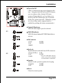
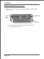
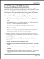
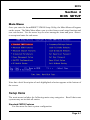
1
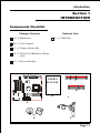
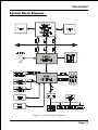
User’s Manual An Intel 815EB Chipset based Soc ket370 mainboar d Sock mainboard TRADEMARK All products and company names are trademarks or registered trademarks of their respective holders. These specifications are subject to change without notice. 60002TM12 Manual Revision 1.2 August 13, 2001 Table of Contents Page Section 1 Introduction Components Checklist ......................................... 1-1 Intel® 815 series Chipset Features ....................... 1-2 Mainboard Form-Factor ....................................... 1-3 I/O Shield Connector ............................................ 1-4 Power-On/Off (Remote) ........................................ 1-4 System Block Diagram .......................................... 1-5 Section 2 Features Mainboard Features ............................................. 2-1 Section 3 Installation Mainboard Detailed Layout ................................. 3-2 Easy Installation Procedure CPU Insertion ....................................................... 3-3 Jumper Settings .................................................... 3-5 System Memory Configuration ............................ 3-6 Device Connectors ............................................... 3-8 STR Function ....................................................... 3-13 Section 4 Award BIOS Setup Main Menu ........................................................... 4-1 Standard CMOS Setup ......................................... 4-3 Advanced BIOS Features ..................................... 4-7 Advanced Chipset Features ................................ 4-10 Integrated Peripherals .......................................... 4-14 Power Management Setup ................................... 4-19 PNP/PCI Configuration ......................................... 4-22 PC Health Status .................................................. 4-23 Frequency/Voltage Control .................................. 4-25 Defaults Menu ..................................................... 4-26 Supervisor/User Password Setting ...................... 4-27 Exit Selecting ........................................................ 4-28 Section 5 815 Series VGA and Sound Driver Installation Easy Driver Installation ........................................ 5-1 Appendix Appendix A EEPROM BIOS Remover ................................. A-1 Appendix B Update Your System BIOS .................................. B-1 Appendix C Avance® Media Player User’s Guide .................. C-1 Introduction Section 1 INTRODUCTION Components Checklist Package Contents Optional Item A. (1) Mainboard F. (1) USB Cable B. (1) User’s manual C. (1) Floppy ribbon cable D. (1) ATA-66/100 Hard drive ribbon cable E. (1) Driver and utility USER’S MANUAL C D B A or E F Page 1-1 Introduction Intel(R) 815 Series chipset features The Intel(R) 815 series chipset that SDRAM interface supports 100MHz and 133MHz operation, the Intel(R) 815 series chipset has re-engineered the Value PC, providing next generation features and great graphics performance. The 82815 series Graphics Memory Controller Hub (GMCH) features : Intel(R) graphics technology and software drivers, using Direct AGP (integrated AGP) to create vivid 2D and 3D effects and images. The 82815 series chip feature integrated Hardware Motion Compensation to improve soft DVD video quality. The Inte(R) 82815 series chipset use Intel(R) Dynamic Video Memory Technology (D. V.M.T.) is an architecture that offers breakthrough performance for the (motherboard) PC through efficient memory utilization and Direct AGP. The system OS uses the Intel software drivers and intelligent memory arbiter to support richer graphics applications. The Intel(R) 82815 series provides an AGP universal connector to support the AGP 2.0 including 4X AGP data transfers. The 82801BA I/O Controller Hub (ICH2) employs the Intel(R) Accelerated Hub Architecture to make a direct connection from the graphics and memory to the integrated AC97 controller, the IDE controllers (ATA/66 or ATA/33 or ATA/100), dual USB ports, and PCI add-in cards. The Accelerated Hub Architecture provides twice the bandwidth of the PCI bus at 266 MB per second. This allows a wider flow of rich information from the I/O controller to the memory controller, with optimized arbitration rules allowing more functions to run concurrently, enabling more life-like audio and video. The Integrated Audio-Codec 97 controller enables software audio by using the processor to run sound. By reusing existing system resources, this feature adds flexibility, improves sound and modem quality. The 82802 Firmware Hub (FWH, 4MB) stores system BIOS and video BIOS, eliminating a redundant nonvolatile memory component. In addition, the 82802 contains a hardware Random Number Generator (RNG). The Intel(R) RNG provides truly random numbers to enable fundamental security building blocks supporting stronger encryption, digital signing, and security protocols for the future application program. Page 1-2 Introduction Mainboard Form-Factor The is designed with Micro ATX form factor - the new industry standard of chassis. Micro ATX form factor is essentially a Baby-AT baseboard rotated 90 degrees within the chassis enclosure and a new mounting configuration for the power supply. With these changes the processor is relocated away from the expansion slots, allowing them all to hold full length add-in cards. Micro ATX defines a double height aperture to the rear of the chassis which can be used to host a wide range of onboard I/O. Only the size and position of this aperture is defined, allowing PC manufacturers to add new I/O features (e.g.; TV input, TV output, joystick, modem, LAN, etc.) to systems. This will help systems integrators differentiate their products in the marketplace, and better meet your needs. • By integrating more I/O down onto the board and better positioning the hard drive and floppy connectors material cost of cables and add-in cards is reduced. • By reducing the number of cables and components in the system, manufacturing time and inventory holding costs are reduced and reliability will increase. • By using an optimized power supply, it's possible to reduce cooling costs and lower acoustical noise. Micro ATX power supply, which has a side-mounted fan, allows direct cooling of the processor and add-in cards making a secondary fan or active heatsink unnecessary in most system applications. Expandable I/O Single chassis fan for system ATX Power Supply PCI Slots CPU AGP Slot Floppy / IDE connectors ATX power connector 3 1/2" Bay 5 1/4" Bay Figure 2: Summary of ATX chassis features Page 1-3 Introduction I/O Shield Connector The board is equipped with an I/O back panel. Please use the appropriate I/O shield (figure 3). Joystick/Midi parallel port PS/2 Mouse USB port PS/2 Keyboard COM1 VGA1 Speaker Line_in MIC Figure 3: I/O back panel layout Power-On/Off (Remote) The board has a single 20-pin connector for ATX power supplies. For ATX power supplies that support the Remote On/Off feature, this should be connected to the systems front panel for system Power On/Off button. The systems power On/Off button should be a momentary button that is normally open. The board has been designed with “Soft Off" functions. You can turn Off the system from one of two sources: The first is the front panel Power On/Off button, and the other is the "Soft Off" function (coming from the onboard circuit controller) that can be controlled by the operating system such asWindows® 95/98/SE/ME or Windows®2000. ATX POWER SUPPLY J3 Case (chassis) Power ON/OFF button (J 3) Figure 4: Simple ATX Power ON/OFF Controller Page 1-4 Introduction System Block Diagram Figure 5: System Block Diagram Page 1-5 Introduction Page Left Blank Page 1-6 Features Section 2 FEATURES Mainboard Features: CPU TM - Intel Celeron Processors with FC-PGA socket 370 packing, operating at 533A MHz and > 566MHz (66MHz and 100MHz system bus) ® TM TM - Intel Pentium III / Coppermine / Tualatin Processors with FC-PGA socket 370 packing, operating at 500MHz ~ 1.13GHz CPU Bus Speed - 66/100/133MHz FSB CHIPSET Intel 815EB - Northbridge: Intel 82815EB GMCH - Southbridge: Intel 82801BA ICH2 System Memory - Two 168 pin 3.3V PC133 DIMM sockets - Supports up to 512MB SDRAM maximum - Supports 100/133MHz Synchronous DRAM Graphics - Integrated Intel i752 3D graphics engine in chipset - Provides 4MB display cache via AIMM card - Provides AGP 4X Interface - Universal AGP slot; support 3.3V(2X) / 1.5V(4X) AGP card Transfer rate up to 1GB/sec - Automatically disable internal graphics when add-in graphics card is present Page 2-1 Features Audio onboard - AC97 2.1 compliant - 16-bit stereo codec LAN onboard (Optional) - Integrate 10/100Mb fast Ethernet controller in chipset with external Intel 82562ET Physical Layer Storage System - Two PCI master IDE ports support up to 4 IDE devices, Supports ATA33/ 66/100 - One floppy port supports up to two 3.5” or 5.25” floppy devices (360K/ 720K/1.2M/1.44M/2.88M) - Supports LS 120 floppy disk drive and ZIP drive SLOTs - PCI x 3, AGP slot x 1 I/O - 2 high speed serial ports (16550 Fast URAT compatible) - 1 Enhanced parallel port support EPP / ECP / SPP - 4 USB ports (2 USB on real I/O panel, 2 USB headers on board ) - 1 PS2 keyboard port / 1 PS2 mouse port - 1 Speak out / 1 Line in / 1 MIC jacks - 1 Game port / MIDI port - 1 15-pin VGA connector - IrDA port supports up to 115.2Kb/s transfer rate - All I/O ports can be enabled / disabled by BIOS setup - 1 RJ45 LAN connector (Optional) BIOS - 4MB Intel Firmware Hub - Licensed advance AWARD BIOS - Supports plug and play - Supports ACPI and OS directed power management Page 2-2 Features System Health Monitor - CPU & System temperatures, CPU fan & PWR fan speeds, Power supply and CPU voltages Power Management - ACPI v1.0 and APM compliant - Supports S0, S1, S3, S5 ACPI power status - Supports Suspend to RAM Advanced Features - Wake up on LAN - Wake up on Modem Certificates - CE/FCC - WHQL logo FORM FACTOR - 205mm x 243mm Micro ATX Size Page 2-3 Features Page Left Blank Page 2-4 Installation Section 3 INSTALLATION Page 3-1 Installation Mainboard Detailed Layout Figure 1 Page 3-2 Installation Easy Installation Procedure The following must be completed before powering on your new system: 3-1. CPU Insertion 3-2. Jumper Settings 3-3. System memory Configuration 3-4. Device Connectors 3-5. STR (Suspend To RAM) Function Section 3-1 CPU Insertion CPU Insertion Step 1 Open the socket by raising the actuation lever. Figure 2 Step 2 Insert the processor. Figure 3 Ensure proper pin 1 orientation by aligning the FC-PGA corner marking with the socket corner closest to the actuation arm tip. The pin field is keyed to prevent misoriented insertion. Don’t force processor into socket. If it does not go in easily, check for mis-orientation and debris. Make sure the processor is fully inserted into the socket on all sides. Page 3-3 Installation Step 3 Close the socket by lowering and locking the actuation lever. Figure 4 Note: Intel’s reference design thermal solution is an active heatsink; an extruded aluminum heatsink based and a fan attached to the top on the fin array. (See Figure 5) Figure 5 Page 3-4 Installation Section 3-2 Jumper Settings JCMOS 1 CMOS Clear JP1 =1-2 Normal (Default) =2-3 Clear CMOS JP5 2 8 1 7 CPU FSB Select JP5 = 1-3, 2-4 = 3-5, 4-6 = 5-7, 4-6 = 5-7, 6-8 AUTO(Default) 133MHz 100MHz 66MHz Page 3-5 Installation Section 3-3 System Memory Configuration Memory Layout The board supports (2) PC133 168-pin DIMMs (Dual In-line Memory Module). The DIMMs is for SDRAM (Synchronous DRAM) . • DIMM SDRAM may be 83MHz (12ns), 100MHz (10ns), 125MHz (8ns) or 133MHz (7.5ns)bus speed. • If you use both 50ns and 60ns memory you must configure your BIOS to read 60ns. • When using Synchronous DRAM we recommend using the 4 clock variety over the 2 clock. Figure 6 and Table 1 show several possible memory configuration. DIMM 1 Bank 0/1 DIMM 2 Bank 2/3 -Synchronous DRAM Figure 6 Total M e mory DIM M 1 (Bank 0/1) DIM M 2 (Bank 2/3) = 256MB Maximum SDRAM* 32MB, 64MB, 128MB, 256MB X 1 None = 512MB Maximum SDRAM* 32MB, 64MB, 128MB, 256MB X 1 SDRAM* 32MB, 64MB, 128MB, 256MB X 1 Table 1 * SDRAM supports 32, 64, 128, 256MB DIMM modules. * We recommend to use PC100 Memory Module for bus speed between 66MHz and 100MHz and PC133 Memory for bus speed over 100MHz. * Using non-compliant memory with higher bus speed (over clocking) may severely compromise the integrity of the system. Page 3-6 Installation DIMM Module Installation Figure 7 displays the notch marks and what they should look like on your DIMM memory module. DIMMs have 168-pins and two notches that will match with the onboard DIMM socket. DIMM modules are installed by placing the chip firmly into the socket at a 90 degree angle and pressing straight down (figure 8) until it fits tightly into the DIMM socket (figure 9). LEFT KEY ZONE (UNBUFFERED) CENTER KEY ZONE (3.3 V DRAM) Figure 7 Figure 8 DIMM Module clip before installation Figure 9 DIMM Module clip after installation To remove the DIMM module simply press down both of the white clips on either side and the module will be released from the socket. Page 3-7 Installation Section 3-4 Device Connectors parallel port PS/2 Mouse Joystick/Midi USB port PS/2 Keyboard COM1 VGA1 Speaker Line_in MIC FAN1 FAN2 FAN1 / FAN2: • A plug-in for the CPU/Power Supply Fan power FAN2: PWR Fan GND +12V Rotation GND +12V Rotation FAN1: CPU Fan JWOL: WOL (Wake On LAN) Connector PME GND +5V Standby JWOM: WOM (Wake On Modem) Connector Page 3-8 PME GND +5V Standby JWOL JWOM Installation FDD1: Floppy Controller Connector (Black color) IDE2: Ultra 66/100 Primary IDE Connector (Blue color) IDE1: Ultra 66/100 Secondary IDE Connector (Black color) PW2: ATX Power Connector • 20-pin power connector CD_IN: CD Audio_IN Connector CD_IN_Right CD_Reference 1 CD_IN_Left AUX_IN: Auxiliary Line_IN Connector CD_IN_Right GND 1 CD_IN AUX_IN MODEN_IN CD_IN_Left MODEM_IN: Teleohony Connector for Modem audio output Mic-out to Modem GND 1 Audio_IN Page 3-9 Installation COM2: RS232 COM2 Connector USBCON1: USB port header pins for share with two USB ports. 2 1 VCC GND -Data +Data +Data -Data GND VCC 9 10 USB port header pin descriptions. Page 3-10 PIN# Wire color Signal Name Comment 1 Red Vcc Cable Power 2 Black Ground Case Ground 3 White -Data Data 4 Black Ground Cable Ground 5 Green +Data Data 6 Green +Data Data 7 Black Ground Cable Ground 8 White -Data Data 9 Black Ground Case Ground 10 Red Vcc Cable Power Installation Power On/Off (This is connected to the power button on the case. Using the Soft-Off by Pwr-BTTN feature, you can choose either Instant Off (turns system off immediately), or 4 sec delay (you need to push the button down for 4 seconds before the system turns off). When the system is in 4 sec delay mode, suspend mode is enabled by pushing the button momentarily.) Turbo LED indicator LED ON when higher speed is selected J3 IDE LED indicator LED ON when Onboard PCI IDE Hard disks is activate IR Connector 1. VCC 2. NC 3. IRRX J2 4. GND 5. IRTX KeyLock Keyboard lock switch & Power LED connector 1. Power LED(+) 4. NC 2. N/C 5. GND * The power LED lights when the 3. GND system is powered on and blinks in SLEEP Mode or STR Mode. Speaker Connect to the system's speaker for beeping 1. Speaker 3. GND 2. N/C 4. GND Reset Closed to restart system. Page 3-11 Installation Device Connectors (continued) AIMM Card with AGP connector (For integrated graphics to upgrade 4MB display cache). To I/O Rear Panel AIMM Card* AGP Connector Note: The AIMM card for Intel 815 chipset M.B’s AGP slot only. * : The AIMM Card (optional) Page 3-12 Installation 3-5 STR (Suspend To RAM) Function The board supports the STR power management state by maintaining the appropriate states on the SDRAM interface signals. The power source must be kept alive to the SDRAM during STR (ACPI S3). Advanced Configuration Power Interface (ACPI) provides more Energy Saving Features for operating systems that supporting Instant ON and QuickStartTM function. 1. To enable the ACPI function and use the STR functionally to save your system energy, you are recommended to confirm the following requirements: a. Please do install all ACPI qualified add-on cards such as AGP, LAN, Modem cards. b. In BIOS, please select “ ACPI function: Enable” and “ACPI Suspend Type: S3(STR)” in the Power Management Setup menu. c. Then, please install the Windows® 98SE/ME or Windows® 2000. d. Restart your system. e. Getting in to the “Advanced” of the Power Management icon of Control Panel, and selecting the “Stand By” in the Power Buttons. 2. Getting start with STR function, please click the START button and choose Shut Down. Then, select the Stand By option in the Shut Down Windows box to get into STR mode. Here are the differences between STR power saving mode and Green (or Suspend) mode: a. It is the most advanced Power Management mode b. It cuts all the power supplied to peripherals except to Memory - max. power saving c. It saves and keeps all on-screen data including any executed applications to SDRAM. d. You must push the Power button connected with onboard J3 pin to wake up you system (not to click to mouse or press keyboard to wake up the system). Page 3-13 Installation Just pushing Power button, your system will quickly back to the last screen for you. The “LED Indicator for ACPI Status” table shown below will guide you and give you a reference for ACPI status on this mainboard. ACPI Onboard’s LED Status Indicator Table Status Onboard’s LED Location Plug in the ATX Power Core Power ON Green Mode STR J3(PW-ON) (S1) (S3) Shutdown (Soft-OFF) (S5) D6 (Red LED) OFF ON ON ON OFF J2 PW_LED OFF ON Blinking Blinking OFF Page 3-14 BIOS Section 4 BIOS SETUP Main Menu Once you enter the AwardBIOS™ CMOS Setup Utility, the Main Menu will appear on the screen. The Main Menu allows you to select from several setup functions and two exit choices. Use the arrow keys to select among the items and press <Enter> to accept and enter the sub-menu. Note that a brief description of each highlighted selection appears at the bottom of the screen. Setup Items The main menu includes the following main setup categories. Recall that some systems may not include all entries. Standard CMOS Features Use this menu for basic system configuration. Page 4-1 BIOS Advanced BIOS Features Use this menu to set the Advanced Features available on your system. Advanced Chipset Features Use this menu to change the values in the chipset registers and optimize your system’s performance. Integrated Peripherals Use this menu to specify your settings for integrated peripherals. Power Management Setup Use this menu to specify your settings for power management. PnP / PCI Configuration This entry appears if your system supports PnP / PCI. PC Health Status This item is only show the system health status (include Voltage, Fan speed, CPU temperature...) Frequency/Voltage Control Use this menu to specify your settings for frequency/voltage control. Load Fail-Safe Defaults Use this menu to load the BIOS default values for the minimal/stable performance for your system to operate. Load Optimized Defaults Use this menu to load the BIOS default values that are factory settings for optimal performance system operations. While Award has designed the custom BIOS to maximize performance, the factory has the right to change these defaults to meet their needs. Supervisor / User Password Use this menu to set User and Supervisor Passwords. Save & Exit Setup Save CMOS value changes to CMOS and exit setup. Exit Without Save Abandon all CMOS value changes and exit setup. Page 4-2 BIOS 4-1 Standard CMOS Setup The items in Standard CMOS Setup Menu are divided into 10 categories. Each category includes no, one or more than one setup items. Use the arrow keys to highlight the item and then use the <PgUp> or <PgDn> keys to select the value you want in each item. Figure 1: The Main Menu Page 4-3 BIOS Main Menu Selections This table shows the selections that you can make on the Main Menu Item Options Month Time HH : MM : SS Options are in its sub menu (described in Table 3) Options are in its sub menu (described in Table 3) Options are in its sub menu (described in Table 3) Options are in its sub menu (described in Table 3) None 360K, 5.25 in 1.2M, 5.25 in 720K, 3.5 in 1.44M, 3.5 in 2.88M, 3.5 in EGA/VGA CGA 40 CGA 80 MONO All Errors No Errors All, but Keyboard All, but Diskette All, but Disk/Key IDE Primary Master IDE Primary Slave IDE Secondary Master IDE Secondary Slave Drive A Drive B Video Halt On DD Description Date Base Memory N/A Extended Memory N/A Total Memory N/A YYYY Set the system date. Note that the ‘Day’ automatically hanges when you set the date Set the system time Press <Enter> to enter the sub menu of detailed options Press <Enter> to enter the sub menu of detailed options Press <Enter> to enter the sub menu of detailed options Press <Enter> to enter the sub menu of detailed options Select the type of floppy disk drive installed in your system Select the default video device Select the situation in which you want the BIOS to stop the POST process and notify you Displays the amount of conventional memory detected during boot up Displays the amount of extended memory detected during boot up Displays the total memory available in the system Table 2 Main Menu Selections Page 4-4 BIOS IDE Adapters The IDE adapters control the hard disk drive. Use a separate sub menu to configure each hard disk drive. Figure 2 shows the IDE primary master sub menu. Figure 2 IDE Primary Master sub menu Page 4-5 BIOS Use the legend keys to navigate through this menu and exit to the main menu. Use Table 3 to configure the hard disk. Item Options Description IIDE HDD Auto-detection Press Enter IDE Primary Master None Auto Manual Capacity Auto Display your disk drive size Press Enter to auto-detect the HDD on this channel. If detection is successful, it fills the remaining fields on this menu. Selecting ‘manual’ lets you set the remaining fields on this screen. Selects the type of fixed disk. "User Type" will let you select the number of cylinders, heads, etc. Note: PRECOMP=65535 means NONE ! Disk drive capacity (Approximated). Note that this size is usually slightly greater than the size of a formatted disk given by a disk checking program. Choose the access mode for this hard disk Access Mode Normal LBA Large Auto The following options are selectable only if the ‘IDE Primary Master’ item is set to ‘Manual’ Cylinder Head Precomp Landing zone Sector Min = 0 Max = 65535 Min = 0 Max = 255 Min = 0 Max = 65535 Min = 0 Max = 65535 Min = 0 Max = 255 Set the number of cylinders for this hard disk. Set the number of read/write heads **** Warning: Setting a value of 65535 means no hard disk **** Number of sectors per track Table 3 Hard disk selections Page 4-6 BIOS 4-2 Advanced BIOS Features This section allows you to configure your system for basic operation. You have the opportunity to select the system’s default speed, boot-up sequence, keyboard operation, shadowing and security. Virus Warning Allows you to choose the VIRUS Warning feature for IDE Hard Disk boot sector protection. If this function is enabled and someone attempt to write data into this area, BIOS will show a warning message on screen and alarm beep. Enabled: Activates automatically when the system boots up causing a warning message to appear when anything attempts to access the boot sector or hard disk partition table. Disabled: No warning message will appear when anything attempts to access the boot sector or hard disk partition table. CPU Internal Cache/External Cache These two categories speed up memory access. However, it depends on CPU/chipset design. Enabled: Enable cache Disabled: Disable cache Page 4-7 BIOS CPU L2 Cache ECC Checking This item allows you to enable/disable CPU L2 Cache ECC checking. The choice: Enabled, Disabled. Processor Number Feature Pentium III or later CPU new feature. The default is Enabled. Enabled: Processor serial number readable. Disabled: Processor serial number disabled. Quick Power On Self Test This category speeds up Power On Self Test (POST) after you power up the computer. If it is set to Enable, BIOS will shorten or skip some check items during POST. Enabled: Enable quick POST Disabled: Normal POST First/Second/Third/Other Boot Device The BIOS attempts to load the operating system from the devices in the sequence selected in these items. The Choice: Floppy, LS120, HDD-0, SCSI, CDROM, HDD-1, HDD-2, HDD-3, ZIP100, USB-FDD, USB-ZIP, USB-HDD, LAN, Disabled. Swap Floppy Drive If the system has two floppy drives, you can swap the logical drive name assignments. The choice: Enabled/Disabled. Boot Up Floppy Seek Seeks disk drives during boot up. Disabling speeds boot up. The choice: Enabled/Disabled. Boot Up NumLock Status Select power on state for NumLock. The choice: On/Off. Gate A20 Option Select if chipset or keyboard controller should control GateA20. Normal: A pin in the keyboard controller controls GateA20 Fast: Page 4-8 Lets chipset control GateA20 BIOS Typematic Rate Setting Key strokes repeat at a rate determined by the keyboard controller. When enabled, the typematic rate and typematic delay can be selected. The choice: Enabled/Disabled. Typematic Rate (Chars/Sec) Sets the number of times a second to repeat a key stroke when you hold the key down. The choice: 6, 8, 10, 12, 15, 20, 24, 30. Typematic Delay (Msec) Sets the delay time after the key is held down before it begins to repeat the keystroke. The choice: 250, 500, 750, 1000. Security Option Select whether the password is required every time the system boots or only when you enter setup. System The system will not boot and access to Setup will be denied if the correct password is not entered at the prompt. Setup The system will boot, but access to Setup will be denied if the correct password is not entered at the prompt. Note: To disable security, select PASSWORD SETTING at Main Menu and then you will be asked to enter password. Do not type anything and just press <Enter>, it will disable security. Once the security is disabled, the system will boot and you can enter Setup freely. OS Select For DRAM > 64MB Select the operating system that is running with greater than 64MB of RAM on the system. The choice: Non-OS2, OS2. HDD S.M.A.R.T Capability Allows you to choose the HDD S.M.A.R.T for detect HDD condition. The choice: Enabled/Disabled. Report No FDD For Win 95 Whether report no FDD for Win 95 or not. The choice: Yes, No. Page 4-9 BIOS 4-3 Advanced Chipset Features This section allows you to configure the system based on the specific features of the installed chipset. This chipset manages bus speeds and access to system memory resources, such as DRAM and the external cache. It also coordinates communications between the conventional ISA bus and the PCI bus. It must be stated that these items should never need to be altered. The default settings have been chosen because they provide the best operating conditions for your system. The only time you might consider making any changes would be if you discovered that data was being lost while using your system. DRAM CTL Buffer Strengths The system memory DRAM interface signal buffer strengths. The Choice: Default, Strong, Weak, Normal. DRAM MD Buffer Strengths The system memory DRAM interface signal buffer strengths. The Choice: Default, Strong, Weak, Normal. Page 4-10 BIOS SDRAM CAS Latency Time When synchronous DRAM is installed, the number of clock cycles of CAS latency depends on the DRAM timing. The Choice: 2, 3, Auto. SDRAM Cycle Time Tras/Trc Select the number of SCLKs for an access cycle. The Choice: 5/7, 7/9, Auto. SDRAM RAS-to-CAS Delay This field lets you insert a timing delay between the CAS and RAS strobe signals, used when DRAM is written to, read from, or refreshed. Fast gives faster performance; and Slow gives more stable performance. This field applies only when synchronous DRAM is installed in the system. The Choice: 2, 3, Auto. SDRAM RAS Precharge Time If an insufficient number of cycles is allowed for the RAS to accumulate its charge before DRAM refresh, the refresh may be incomplete and the DRAM may fail to retain data. Fast gives faster performance; and Slow gives more stable performance. This field applies only when synchronous DRAM is installed in the system. The Choice: 2, 3, Auto. System BIOS Cacheable Selecting Enabled allows caching of the system BIOS ROM at F0000h-FFFFFh, resulting in better system performance. However, if any program writes to this memory area, a system error may result. The choice: Enabled, Disabled. Video BIOS Cacheable Select Enabled allows caching of the video BIOS , resulting in better system performance. However, if any program writes to this memory area, a system error may result. The Choice: Enabled, Disabled. Memory Hole At 15M-16M You can reserve this area of system memory for ISA adapter ROM. When this area is reserved, it cannot be cached. The user information of peripherals that need to use this area of system memory usually discusses their memory requirements. The Choice: Enabled, Disabled. Page 4-11 BIOS CPU Latency Timer Enabled: The processor cycle will be deferred immediately after the GMCH receives another ADS#. Disabled: The processor cycle will only be deferred after for 31 clocks and another ADS# has arrived. Delayed Transaction The chipset has an embedded 32-bit posted write buffer to support delay transactions cycles. Select Enabled to support compliance with PCI specification version 2.1. The Choice: Enabled, Disabled. AGP Graphics Aperture Size (MB) The amount of system memory that the AGP card is allowed to share. The default is 64. 32: 32MB of systems memory accessable by the AGP card. 64: 64MB of systems memory accessable by the AGP card. AGP Device 4X Support Enblaes and disables the use of AGP 4X Mode. The default is Enabled. Display Cache Frequency If your insert AGP In-Line Memory Module (AIMM). This function setting AIMM frequency. The default is 100MHz. System Memory Frequency Setting the SDRAM frequency. The default is Auto. The choice: 100Mhz, 133MHz, Auto. Note: When the CPU host (FSB) is 100MHz, then SDRAM frequency is fixed at 100MHz. This item is not show automatically on screen. On-Chip Video Window Size The amount of system memory that the 815 series AGP is allowed to share. The default is 64MB. Page 4-12 BIOS Onboard Display Cache Setting Setting the onboard display cache timing. CAS # Latency Select the local memory clock periods. The Choice: 2, 3 Paging Mode Control Select the paging mode control. The Choice: Close, Open. RAS-to-CAS Override Select the display cache clock periods control. The Choice: by CAS# LT, Override(2). RAS# Timing This item controls RAS# active to Protegra, and refresh to RAS# active delay ( in local memory clocks). The Choice: Fast, Slow. RAS# Precharge Timing This item controls RAS# precharge (in local memory clocks). The choice: Fast, Slow. Page 4-13 BIOS 4-4 Integrated Peripherals OnChip Primary/Secondary PCI IDE The integrated peripheral controller contains an IDE interface with support for two IDE channels. Select Enabled to activate each channel separately. The choice: Enabled, Disabled. IDE Primary/Secondary Master/Slave PIO The four IDE PIO (Programmed Input/Output) fields let you set a PIO mode (0-4) for each of the four IDE devices that the onboard IDE interface supports. Modes 0 through 4 provide successively increased performance. In Auto mode, the system automatically determines the best mode for each device. The choice: Auto, Mode 0, Mode 1, Mode 2, Mode 3, Mode 4. IDE Primary/Secondary Master/Slave UDMA Ultra DMA/33 implementation is possible only if your IDE hard drive supports it and the operating environment includes a DMA driver (Windows 95 OSR2 or a thirdparty IDE bus master driver). If your hard drive and your system software both support Ultra DMA/33, select Auto to enable BIOS support. The Choice: Auto, Disabled. Page 4-14 BIOS USB Controller Select Enabled if your system contains a Universal Serial Bus (USB) controller and you have USB peripherals. The choice: Enabled, Disabled. USB Keyboard Support Select Enabled if your system contains a Universal Serial Bus (USB) controller and you have a USB Keyboard. The choice: Enabled, Disabled. Init Display First This item allows you to decide to active whether PCI Slot or on-chip VGA first The choice: PCI Slot, Onboard . AC97 Audio This item allows you to decide to Auto/disable the 815 chipset family to support AC97 Audio. The function setting AC97 Audio Codec states. The system default is Auto. IDE HDD Block Mode Block mode is also called block transfer, multiple commands, or multiple sector read/write. If your IDE hard drive supports block mode (most new drives do), select Enabled for automatic detection of the optimal number of block read/writes per sector the drive can support. The choice: Enabled, Disabled Onboard FDC Controller Select Enabled if your system has a floppy disk controller (FDC) installed on the system board and you wish to use it. If you install and-in FDC or the system has no floppy drive, select Disabled in this field. The choice: Enabled, Disabled. Onboard Serial Port 1/Port 2 Select an address and corresponding interrupt for the first and second serial ports. The choice: 3F8/IRQ4, 2E8/IRQ3, 3E8/IRQ4, 2F8/IRQ3, Disabled, Auto. Page 4-15 BIOS UART Mode Select This filed allows the users to configure what IR mode the 2nd serial port should use. The default is Normal. Optional: Normal, IrDA and ASKIR. RxD, TxD Active This field configures the receive and transmit signals generated from the IR port. The default is Hi Lo (when UART Mode Select is not set to Normal). Options: Hi Hi, Hi Lo, Lo Hi, and Lo Lo. IR Transmission delay The default is Enabled (when UART Mode Select is not set to Normal). Options: Enabled and Disabled. UR2 Duplex Mode This item allows you to select IR half/full duplex function. The choice: Half, Full Use IR Pins This item allows you to select IR transmission routes, one is RxD2, TxD2 (COM Port) and the other is IR-Rx2Tx2. The choice: IR-Rx2Tx2; RxD2, TxD2. Onboard Parallel port This field allows the user to configure the LPT port. The default is 378H / IRQ7. 378H: Enable Onboard LPT port and address is 378H and IRQ7. 278H: Enable Onboard LPT port and address is 278H and IRQ5. 3BCH: Enable Onboard LPT port and address is 3BCH and IRQ7. Disabled: Disable Onboard LPT port. Parallel Port Mode This field allows the user to select the parallel port mode. The default is ECP+EPP. EPP: Enhanced Parallel Port mode. ECP: Extended Capabilities Port mode. EPP+ECP: ECP Mode & EPP Mode. Page 4-16 BIOS EPP Mode Select This item allows you to determine the IR transfer mode of onboard I/O chip. options: EPP1.9, EPP1.7. ECP Mode USE DMA This field allows the user to select DMA1 or DMA3 for the ECP mode. The default is DMA3. DMA1: This field selects the routing of DMA1 for the ECP mode. DMA3: This field selects the routing of DMA3 for the ECP mode. PWRON After PWR-Fail The system will stay of or power on after a power interrupte. The default is OFF. Fomer-Status: Stay off or power on depend on system safe shut-down or power fail. ON: System always power on after a power interrupte. OFF: System always stay off after a power interrupte. Game Port Address Select an address for the Game port. The choice: 201, 209, Disabled. Midi Port Address Select an address for the Midi port. The choice: 290, 300, 330, Disabled. Midi Port IRQ Select an interrupt for the Midi port. The choice: 5, 10. Page 4-17 BIOS 4-5 Power Management Setup The Power Management Setup allows you to configure you system to most effectively save energy while operating in a manner consistent with your own style of computer use. ACPI Function This item allows you to enable/disable the Advanced Configuration and Power Management (ACPI). The choice: Enabled, Disabled. ACPI Suspend Type This item allows you to select S1(POS) or S3(STR) function. The choice: S1(POS), S3(STR). Power Management This category allows you to select the type (or degree) of power saving and is directly related to the following modes: 1. HDD Power Down 2. Doze Mode 3. Suspend Mode Page 4-18 BIOS There are four selections for Power Management, three of which have fixed mode settings. Disable (default) Min. Power Saving Max. Power Saving User Defined No power management. Disables all four modes Minimum power management. Doze Mode = 1 hr. Standby Mode = 1 hr., Suspend Mode = 1 hr., and HDD Power Down = 15 min. Maximum power management -- ONLY AVAILABLE FOR SL CPU’s. Doze Mode = 1 min., Standby Mode = 1 min., Suspend Mode = 1 min., and HDD Power Down = 1 min. Allows you to set each mode individually. When not disabled, each of the ranges are from 1 min. to 1 hr. except for HDD Power Down which ranges from 1 min. to 15 min. and disable. Video Off Method This determines the manner in which the monitor is blanked. V/H SYNC+Blank Blank Screen DPMS This selection will cause the system to turn off the vertical and horizontal synchronization ports and write blanks to the video buffer. This option only writes blanks to the video buffer. Initial display power management signaling. Video Off In Suspend This determines the manner in which the monitor is blanked. The choice: Yes, No. Suspend Type Select the Suspend Type. The choice: PWRON Suspend, Stop Grant. MODEM Use IRQ This determines the IRQ in which the MODEM can use. The choice: 3, 4, 5, 7, 9, 10, 11, NA. Suspend Mode When enabled and after the set time of system inactivity, all devices except the CPU will be shut off. The choice: Enabled, Disabled. Page 4-19 BIOS HDD Power Down When enabled and after the set time of system inactivity, the hard disk drive will be powered down while all other devices remain active. The choice: Enabled, Disabled. Soft-Off by PWR-BTTN Pressing the power button for more than 4 seconds forces the system to enter the Soft-Off state when the system has “hung.” The default is Instant-off. The choice: Delay 4 Sec, Instant-Off. Wake-Up by PCI Card An input signal form PME on the PCI Card awakens the system form a soft off state. The choice: Enabled, Disabled. PowerOn By Ring This option is used to set the remote ring in and Wake on LAN (WOL) features. The choice: Enabled, Disabled. CPU Thermal-Throttling Select the CPU THRM-Throttling rate. The choice: 25.0%, 37.5%, 50.0%, 62.5%, 75.0%, 87.5%. Resume by Alarm This option allows you to have the system turn on at a present time each day or on a certain day. The choice: Disabled, Enabled. ** PM Events ** PM events are I/O events whose occurrence can prevent the system from entering a power saving mode or can awaken the system from such a mode. In effect, the system remains alert for anything which occurs to a device which is configured as Enabled , even when the system is in a power down mode. Primary IDE 0 Primary IDE 1 Secondary IDE 0 Secondary IDE 1 FDD, COM, LPT Port PCI PIRQ[A-D] # Page 4-20 BIOS 4-6 PnP/PCI Configuration Setup This section describes configuring the PCI bus system. PCI, or Personal Computer Interconnect, is a system which allows I/O devices to operate at speeds nearing the speed the CPU itself uses when communicating with its own special components. This section covers some very technical items and it is strongly recommended that only experienced users should make any changes to the default settings. Reset Configuration Data Normally, you leave this field Disabled. Select Enabled to reset Extended System Configuration Data (ESCD) when you exit Setup if you have installed a new add-on and the system reconfiguration has caused such a serious conflict that the operating system can not boot. The choice: Enabled, Disabled . Resource controlled by The Award Plug and Play BIOS has the capacity to automatically configure all of the boot and Plug and Play compatible devices. However, this capability means absolutely nothing unless you are using a Plug and Play operating system such as Windows95. If you set this field to “manual” choose specific resources by going Page 4-21 BIOS into each of the sub menu that follows this field (a sub menu is preceded by a “Ø”). The choice: Auto(ESCD), Manual. PCI/VGA Palette Snoop Leave this field at Disabled. Choices are Enabled, Disabled. INT Pin1 to Pin4 Assignment These settings allow the user to specify what IRQ will be assigned to PCI devices in the chosen slot. Options available: Auto,3,4,5,7,9,10,11,12,14 & 15. The defaults are Auto. 4-7 PC Health Status 33oC/91oF 59oC/138oF 0 RPM 0 RPM 0 RPM 1.53V 2.09V 3.42V 4.97V 12.16V 12.28V 5.09V 3.48V 4.89V CPU Warning Temperature This is the temperature that the computer will respond to an overheating CPU. The default is Disabled. Enabled: Temperature is monitored on the CPU, default is 95oC/205oF. Disabled: This feature is turned off. Page 4-22 BIOS Current CPU Temperature This is the current temperature of the CPU. Current System Temp This is the Current temperature of the system. Current CPU Fan/ Power Fan/ Chassis Fan Speed The current CPU fan speed in RPMs. CPU(V) The voltage level of the Vtt, Vcore, Vio. +5V, +12V, -12V, -5V, VBAT, 5VSB: The voltage level of the switch power supply. Shutdown Temperature This is the temperature that the computer will turn off the power to combat the effects of an overheating system. (requires ACPI to be enabled in Power Management BIOS and ACPI compliant operating system.) The default is Disabled. Options available are 60oC/140oF to 75oC/167oF in increments of 5oC. Page 4-23 BIOS 4-8 Frequency/Voltage Control Auto Detect DIMM/PCI Clk This item allows you to enable/disable auto detect DIMM/PCI Clock. The choice: Enabled, Disabled. CPU Host / PCI Clock The mainboard is designed to set the CPU Host/PCI clock via BIOS. This item allows you to select the CPU Host and PCI clock speed by “Enter” key. The default speed depends on what CPU was installed. Ex: Celeron CPU default 66. Coppermine CPU default 100 or 133. Note: Overclocking failure will cause system No display problem. At this moment, please press “Insert” key to back to the initial or default setting to boot up your system. CPU Clock Ratio This item allows you to select the CPU ratio. If the CPU ratio is fixed. This item was no function. Configuration options: [3.x]...[7x], [7.5x], [8.x]. Page 4-24 BIOS 4-9 Defaults Menu Selecting “Defaults” from the main menu shows you two options which are described below Load Fail-Safe Defaults When you press <Enter> on this item you get a confirmation dialog box with a message similar to: Load Fail-Safe Defaults (Y/N) ? N Pressing ‘Y’ loads the BIOS default values for the most stable, minimal-performance system operations. Load Optimized Defaults When you press <Enter> on this item you get a confirmation dialog box with a message similar to: Load Optimized Defaults (Y/N) ? N Pressing ‘Y’ loads the default values that are factory settings for optimal performance system operations. Page 4-25 BIOS 4-10 Supervisor/User Password Setting You can set either supervisor or user password, or both of then. The differences between are: supervisor password : can enter and change the options of the setup menus. user password : just can only enter but do not have the right to change the options of the setup menus. When you select this function, the following message will appear at the center of the screen to assist you in creating a password. ENTER PASSWORD: Type the password, up to eight characters in length, and press <Enter>. The password typed now will clear any previously entered password from CMOS memory. You will be asked to confirm the password. Type the password again and press <Enter>. You may also press <Esc> to abort the selection and not enter a password. To disable a password, just press <Enter> when you are prompted to enter the password. A message will confirm the password will be disabled. Once the password is disabled, the system will boot and you can enter Setup freely. PASSWORD DISABLED. When a password has been enabled, you will be prompted to enter it every time you try to enter Setup. This prevents an unauthorized person from changing any part of your system configuration. Additionally, when a password is enabled, you can also require the BIOS to request a password every time your system is rebooted. This would prevent unauthorized use of your computer. You determine when the password is required within the BIOS Features Setup Menu and its Security option (see Section 3). If the Security option is set to “System”, the password will be required both at boot and at entry to Setup. If set to “Setup”, prompting only occurs when trying to enter Setup. Page 4-26 BIOS 4-11 Exit Selecting Save & Exit Setup Pressing <Enter> on this item asks for confirmation: Save to CMOS and EXIT (Y/N)? Y Pressing “Y” stores the selections made in the menus in CMOS – a special section of memory that stays on after you turn your system off. The next time you boot your computer, the BIOS configures your system according to the Setup selections stored in CMOS. After saving the values the system is restarted again. Exit Without Saving Pressing <Enter> on this item asks for confirmation: Quit without saving (Y/N)? Y This allows you to exit Setup without storing in CMOS any change. The previous selections remain in effect. This exits the Setup utility and restarts your computer. Page 4-27 BIOS Page Left Blank Page 4-28 Drivers Installation Section 5 815 Series VGA and Sound Driver Installation Easy Driver Installation Step 1 : Click INTEL CHIPSET INF FILES/INSTALLATION UTILITIES that enable the Intel® 815 series Chipset to be recognized by listed operating systems. This installer will unpack updated .INF files into a specified folder. Supported operating systems: Microsoft Windows® 95 OSR 2.1+, Windows® 98/98SE/98ME and Windows® NT2000 operating systems. This procedure will Re-start the system. Step 2 : Click INTEL ULTRA STORAGE DRIVER to install IDE Driver. Step 3 : Click VGA DRIVER to install VGA Driver. Step 4 : Click AVANCE LOGIC AUDIO DRIVER to install Audio Sound Driver. Page 5-1 Drivers Installation Page Left Blank Page 5-2 Appendix Appendix A A-1 EEPROM BIOS Remover Do not remove the BIOS chip, unless instructed by a technician and only with a PLCC IC extractor tool. The BIOS socket may be damaged if using an improper method to replace the BIOS chip. A-1 Appendix Page Left Blank A-2 Appendix Appendix B B-1 Update Your System BIOS Download the xxxxx.EXE file corresponding to your model form the our website to an empty directory on your hard disk or floppy. Run the downloaded xxxxx.EXE file and it will self extract. Copy these extracted files to a bootable DOS floppy disk. Note: The DOS floppy disk should contain NO device drivers or other programs. 1. Type “A:\AWDFLASH and press <Enter> Key. 2. You will see the following setup on screen. 3. Please key in the xxxxx.bin BIOS file name. XXXX 4. If you want to save the previous BIOS data to the diskette, please key in [Y], otherwise please key in [N]. XXXX XXXXX xxxxx.bin B-1 Appendix 5. Key in File Name to save previous BIOS to file. XXXX XXXXX xxxxx.bin xxxxx.bin 6. Are you sure to program (y/n), please key in [Y] to start the programming. XXXX XXXXX xxxxx.bin xxxxx.bin 7. The programming is finished. XXXX XXXXX xxxxx.bin F1 : Reset B-2 F10 : Exit Appendix Appendix C C-1 Avance® Media Player User’s Guide Avance® Media Player Platform J B 3 1 4 A 7 8 5 2 C 6 D I E F G H Functional Descriptions A. Playback Windows Display Playback windows displays the following mode information: 1. Playback Time Display 2. Voice Cancellation Mode Display 3. Pitch Mode Display 4. Surround Sound Mode Display B. Playback Function Controls There are 8 selectable functions for the playback: 1. Volume control High/Low Adjustment Bar. 2. Pitch control 4-step High/Low Adjustment Bar. C-1 Appendix 3. Repeat mode Choice of Repeat, All Repeat, Random or No Repeat Mode. 4. Mute Mute On/Off Mode select. 5. Voice cancellation Voice Cancellation On/Off Mode select for Karaoke. 6. Surround mode A total of 26 Surround Sound mode select as shown in the table below. Surround mode Surround mode Generic Stone corridor Padded Alley Room Forrest Bathroom City Living room Mountain Stone Quarry Auditorium Plain Concert Parking lot Cave Sewer pipe Arena Under water Hangar Drug Carpet Dizzy Hallway Psychological 7. Skin change Media Player Skin Type select. 8. Open Open file formats including MP3, CDA, MDI, WAV & WMA support. C. Playback Controls The playback controls include “Play”, “Pause”, “Stop”, “Previous”, “Backward”, “Forward”, & “Next”. D. Seeking bar Display Animated Playback Status E. Title/Play List Windows Display Currently Selected Title(s) C-2 Appendix F. Title/Play List Edit Controls There title/play list controls include “Add”, “Del”, “Clear”, “Load”, & “Store”. 1. Add Add to the Title/Play List. 2. Del Remove form the Title/Play List. 3. Clear Clear the Title/Play Lost. 4. Load Load Title/Play List. 5. Store Save Title/Play List. G. Title/Play List Scroll bar Scroll Up/Down the Title/Play List. H. Recording Function Controls The recording function controls include “Input”, “Save:, “New”, “Rec”, “Stop”, & “Play”. 1. Input Input soruce select. 2. Save Save to file. 3. New Open new file & select format includes Sampling Rate, Sampling bit, Mono or Stereo. 4. Rec Start Rec. 5. Stop Stop Rec. 6. Play Playback Rec file. I. REC/Playback Time Display Displays REC/Playback Time. J. Platform Display Panel Controls The platform display panel control include “Minimize” & “Close”. 1. Minimize Minimize Platform Display Panel. 2. Close Close/Exit Platform Display Panel. C-3 Appendix Page Left Blank C-4