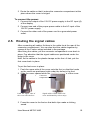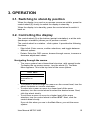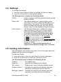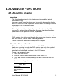
1
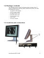
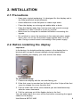
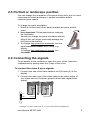
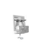
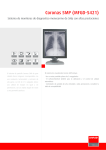
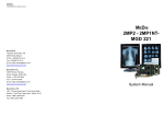
Contents 1. Overview ......................................................................................................... 5 1.1 Introduction ................................................................................................... 5 1.2 Package contents ......................................................................................... 6 1.3 Controls and connectors ............................................................................... 6 2. Installation ....................................................................................................... 8 2.1 Precautions ................................................................................................... 8 2.2 Before installing the display .......................................................................... 8 2.3 Portrait or landscape position ....................................................................... 9 2.4 Connecting the signals ................................................................................. 9 2.5.Routing the signal cables ........................................................................... 10 2.6 Tilt and swivel positioning ........................................................................... 11 2.7 Starting up ................................................................................................... 11 3. Operation ...................................................................................................... 12 3.1. Switching to stand-by position ................................................................... 12 3.2. Controlling the display ............................................................................... 12 3.3. Setting the Luminance value ..................................................................... 13 3.4. Settings ...................................................................................................... 14 3.5. Getting information .................................................................................... 14 4. Advanced functions ....................................................................................... 15 4.1. About this chapter ...................................................................................... 15 4.2. Advanced functions in the Luminance menu ............................................. 16 4.3. Advanced functions in the Settings menu .................................................. 16 4.4. Advanced functions in the Information menu ............................................. 17 4.5. Advanced functions in the Adjustments menu ........................................... 19 5. Maintenance ................................................................................................. 20 6. Troubleshooting ............................................................................................ 21 7. Technical specifications ................................................................................ 22 User Manual MFGD 3420 4 1. OVERVIEW 1.1 Introduction The MFGD 3420, BARCOs 21 3 megapixel greyscale LCD display, guarantees perfect image quality in medical imaging applications. The display combines a TFT (thin film transistor) liquid crystal display panel structure and a built-in backlight with inverter for a better picture quality. It is designed to meet the users' needs for performance, consistency, and outstanding image quality through a streamlined development process. The display can be used in portrait or landscape version, simply by turning the panel. The tilt & swivel foot allows ideal positioning of the panel, in height and viewing angle. The image brightness can be adjusted by means of a control wheel on the display. Other image parameters can be adjusted by means of external software, like MediCal® Pro. I-Guard I-GUARD® is Barcos patent-pending, built-in calibration device, continuously maintaining image quality. With I-GUARD®, QA checks no longer need to disturb normal radiology activities, as they can be performed while applications are running. I-GUARD® allows radiologists or QA administrators to calibrate their viewing stations or adjust the panels curve to DICOM standards without administrator intervention. MediCal Pro In combination with Barcos MediCal ® Pro management and calibration software package, Coronis offers a truly intervention-free display system, making it possible to perform QA checks from one central server at any time, thereby reducing lifecycle cost. Multi-scan capabilities The optimum and recommended resolution is 2048 x 1536 or 1536 x 2048 at 60 Hz. The MFGD 3420 display will also display most of the computer boot modes. BARCO's BarcoMed 3MP2FH imaging board is the best choice to drive the MFGD 3420 display. User Manual MFGD 3420 5 1.2 Package contents The package should include the following items, please check. If some of the items are missing, please contact the reseller you have purchased the unit from. - The MFGD 3420 display - 12V DC power supply - European power cord - American power cord - Chinese power cord - Video cable - This user manual 1.3 Controls and connectors (2) (3) (1) (4) User Manual MFGD 3420 (5) (6) 6 (1) Power LED - The LED is off when the display is off. The LED is green when the display is on. Note: This function can be switched off by software. The LED is blinking green when the display is in Suspend power-saving mode. The LED is orange when the display is in Stand-by powersaving mode. (2) Control wheel for stand-by switching and luminance control (3) USB-downstream connector (4) USB-upstream connector (5) DVI (video and data) input (6) 12V DC power input User Manual MFGD 3420 7 2. INSTALLATION 2.1 Precautions Keep your original packaging. It is designed for this display and is the ideal protection during transport. Avoid reflections in the flat panel to reduce eye strain. Place the display on a strong and stable table or desk. Keep the display away from heat sources and provide enough ventilation in case it is built in a rack or console. Make sure the computer is switched off before connecting the signals. Do not block or cover the openings in the external power supply block. Also, do not turn the power supply upside down or at its side. Doing so would cause overheating of the power supply. 2.2. Before installing the display Important: In the factory, the height-positioning system in the display foot is blocked with a strap to prevent damage during transportation. Before installing the display, you must remove this strap. To remove the strap: 1 Position the display with its rear side facing you. 2 If the foot cover is mounted on the foot, lift up the 2 clips of the foot cover to release the cover from the foot. 3 Pull the lower side of the cover towards you and simultaneously slide the cover downward. 4 Pull the red strap out of the fixation holes in the foot. You can better leave the cover off the foot while connecting the signal cables to the display. User Manual MFGD 3420 8 2.3 Portrait or landscape position You can change the orientation of the panel at any time, but it is more convenient to select landscape or portrait orientation before connecting the cables. To change the panel orientation: 1 Stand at the front side of the panel and take the panel at both sides. 2 Very important: Tilt the panel before changing the orientation. Should you change the panel orientation without tilting it first, you might irreversibly damage the tilt & swivel mechanism. 3 To change from portrait to landscape, turn the panel counterclockwise while lifting it up slightly. To change from landscape to portrait, turn clockwise. 2.4 Connecting the signals To get access to the connectors, open the cover of the connector compartment by pulling down the 2 clips of the cover. To connect the video & sync signals: 1 Connect one end of the video cable to the DVI input (5) of the display. 2 Connect the other end of the video cable to the video output of your video source (Computer graphics board with digital video output). Vid1 Vid2 Example of video connection in a Coronis dual head configuration User Manual MFGD 3420 9 3 Route the cable so that it enters the connector compartment at the place where the cover is bulged. To connect the power: 1 Connect the output of the 12V DC power supply to the DC input (6) of the display. 2 Connect one end of the proper power cable to the AC input of the 12V DC power supply. 3 Connect the other end of the power cord to a grounded power outlet. 2.5. Routing the signal cables After connecting all cables, fix them in the cable tie at the rear of the connector compartment. You can also bind the cables together by means of the 2 velcro strips included in the package. After fixing the cables, put the connector compartment cover back in place. Pay attention that the signal cables are positioned under the bulge in the cover. Next, fix the cables in the plastic clamps on the foot. At last, put the foot cover back in place. To put the foot cover in place: 1 Push the upper side of the cover onto the foot, so that the hooks on the cover are positioned right under the holes in the foot. 2 Slide the cover upward while moving the lower side of the cover Connector towards the foot. compartment Push the upper side of the cover onto the foot Signal cables routed under foot cover and bound by velcro strips 3 Press the cover to the foot so that both clips make a clicking sound. User Manual MFGD 3420 10 2.6 Tilt and swivel positioning Adjust the position of the panel for best viewing conditions. The display foot allows adjusting the panel height, horizontal viewing angle and vertical viewing angle. 2.7 Starting up Proceed as follows: 1 Switch on the computer. 2 If necessary, select a suitable resolution in the computer operating system. You will have to select a resolution that corresponds to the panel orientation (landscape or portrait). Please refer to the possible resolutions in the Technical specifications. Note: The recommended resolution for best image quality is 2048 x 1536 or 1536 x 2048. User Manual MFGD 3420 11 3. OPERATION 3.1. Switching to stand-by position When the display is on and no on-screen menus are visible, press the control wheel (2) shortly to switch the display in stand-by. When the display is in stand-by, press the control wheel to switch it back on. 3.2. Controlling the display The control wheel (2) at the bottom (portrait orientation) or at the side (landscape orientation) allows you to perform controls. The control wheel is a rotation - click system. It provides the following functions: Short click: Enter menus, confirm selections, and toggle between different options Rotate: Enter the OSD menus, browse through menus, increase or decrease adjustment values Navigating through the menus The menu system has a hierarchical structure, with several levels. To display the on-screen menus, turn the wheel (2). The Main Menu appears. This is the top level of the menu system. MAIN MENU Luminance Settings Information EXIT To browse or scroll through the menus on the current level, turn the wheel clockwise or counter-clockwise. To enter into a menu or move to a lower level of the menu structure, turn the control wheel to select the desired menu. Next, click the wheel shortly. To exit from a menu or move to a higher level of the menu structure, turn the control wheel to select EXIT. Next, click the control wheel shortly. If you do this when you are in the Main Menu, you exit the menu system. User Manual MFGD 3420 12 Some adjustments can be made by changing an adjustment value. To change an adjustment value: - Turn the control wheel to select the adjustment. Click the wheel shortly. A pointer appears next to the adjustment name. Turn the wheel to change the value. Click the wheel shortly to confirm the change. The pointer disappears again. Some adjustments can be made by selecting from a range of predefined settings. To change the selection: - Turn the control wheel to select the adjustment. Click the wheel until the desired setting appears in the menu. Saving changes When you change a setting value, the change is automatically saved immediately. 3.3. Setting the Luminance value With this function, the backlight value is stabilized by the I-Guard sensor. The value you enter is the target backlight luminance, expressed in Cd/m². This luminance value will be established by the IGuard control circuit. Proceed as follows: 1 In the main menu, turn the control wheel to select the Luminance menu. MAIN MENU Luminance Settings Information EXIT 2 Click the control wheel. The Luminance menu appears. 3 Turn the control wheel to select the Luminance function. 4 Click the control wheel. A pointer appears at the left of the menu. 5 Turn the control wheel to adjust the Luminance Target value. 6 Click the control wheel to confirm the adjustment. 7 Turn the control wheel to select Exit. 8 Click the control wheel to return to the main menu. User Manual MFGD 3420 13 3.4. Settings To change the settings: 1 Turn the control wheel to select the setting you wish to change. 2 Click the control wheel to change the setting. The Settings menu contains the following items: DPMS ................... Allows to switch on/off the automatic power saving system (DPMS) Power LED ........... This setting allows you to switch off the power LED. Note: The LEDs orange DPMS state is not influenced by this setting. So, when the display goes into power-saving mode, the LED will turn orange, even if it was switched off by this setting. User controls ........ This function allows you to disable the control wheel functions so that the on-screen display cannot be used after quitting the OSD menus. To enable the control wheel functions again: a) Do not use the wheel for at least 3 seconds b) Turn the control wheel 1 click clockwise c) Click the control wheel 2 times d) Turn the control wheel 1 click counterclockwise e) Select the Settings menu and switch Local controls on again. Actions b, c, d have to be performed in a sequence that takes no longer than 3 seconds. 3.5. Getting information The Information menu allows you to get a lot of information about the display and the connected signals. Proceed as follows: 1 In the main menu, turn the control wheel to select Information. 2 Click the control wheel to enter the information menu. The Information menu contains the following items: Product: ................... The display type Serial No: ................ Indicates the display serial number SW version: ............ Displays the current internal software version Display Lifetime: ..... Indicates the total time the display has been operating, including the time in stand-by Backlight Lifetime: ... Indicates the total time the display has been operating, excluding the time in stand-by User Manual MFGD 3420 14 4. ADVANCED FUNCTIONS 4.1. About this chapter Important The functions described in this chapter are intended for trained service staff only! Improper use of these functions may irreversibly damage the display. BARCO cannot be held responsible for the results or damage caused by improper use of these functions. This chapter describes only the Advanced functions in the OSD menus. For a description of the other functions (standard functions), please refer to the previous chapter, Operation . In this chapter, we assume the advanced user knows how to use the OSD system: How to browse through the menus, how to enter menus and sub-menus, how to select and change values. These actions are described in the previous chapter. About the Advanced functions The advanced functions are extensions of the OSD menus. A standard user browsing through the OSD system sees only the standard functions. When logged in in advanced mode, the user sees the standard and advanced functions in the OSD menus. To log in as advanced user: 1 Enter the main menu. 2 Turn the control wheel to select the menu item EXIT. 3 Click and hold the control wheel for at least 6 seconds until the OSD main menu is refreshed on the screen. You have now logged in as advanced user. MAIN MENU Luminance Settings Information Adjustments EXIT User Manual MFGD 3420 The Advanced main menu 15 4.2. Advanced functions in the Luminance menu The Luminance menu contains the following advanced function: Manual Backlight ..... This function allows to manually control the backlight luminance. When you control the Manual Backlight function, the Luminance target function and I-Guard control are disabled. Important: Disabling the I-Guard results in an uncalibrated and not stabilized backlight. After switching the power off and on again, the Luminance target and I-Guard control are activated again. This is also the case when you control the Luminance function again. 4.3. Advanced functions in the Settings menu The Settings menu contains the following advanced functions: Panel position ......... Click to select the desired option: - Auto: Select if the display will be used in both portrait and landscape orientation. Portrait: Select if the display is always used in portrait orientation. Landscape: Select if the display is always used in landscape orientation. Auto Rotation .......... When switched on, the image will be rotated automatically when switching between portrait or landscape orientation. DVI input ................. Click to switch between normal DVI signal, Dual10 DVI signal or automatic detection of the DVI format. Stabilizer ................. Click to switch the backlight stabilizer on/off Patch ....................... Click to hide/display the I-Guard patch. When you hide the patch, the I-Guard will not function properly anymore Burn-In Mode .......... When switched on, the display will generate a white image when the video cable is unplugged Important: Disabling the I-Guard results in an uncontrolled image performance. User Manual MFGD 3420 16 4.4. Advanced functions in the Information menu In Advanced mode, the Information menu contains the following additional submenus: Service, Firmware, Runtime, Measurements and Scan Measurements. Service The Service info menu contains the following items: Display Name .......... The display type Display Ser No ........ Indicates the display serial number Display Stock No ..... Indicates the display order number Panel Ser No ........... Indicates the flat panel serial number Panel Prod Date ...... Indicates the flat panel production date Firmware The Firmware info menu contains the following items: Boot Code Version ........ The version of the internal boot code Run Code Version ......... The version of the internal run code CPLD Code Version ...... The version of the internal CPLD code Transpose Version ........ The version of the internal Transpose circuit code Runtime The Runtime info menu contains the following items: Display lifetime ........ Indicates the total time the display has been under power Backlight Lifetime .... Indicates the total time the display has been operating, excluding the time in stand-by (so, the total backlight lifetime) Backlight Runtime ... Indicates the time the backlight has been on since the last time it was switched off. This counter is reset to 0 after 1092 minutes. User Manual MFGD 3420 17 Measurements The Measurements info menu contains the following items: Internal Temperature .... The temperature measured inside the display Sensor Temperature .... The internal temperature measured on the IGuard board FAN speed ................... A value indicating the speed of the fans. Minimum speed is 0, maximum speed is 1000 Sensor Y value ............. The luminance measured by the I-Guard, expressed in nit (Cd/m²) Sensor DAC value ....... The luminance measured by the I-Guard, expressed in DAC values Scan Measurements The Scan Measurements info menu contains the following items: DVI Input: ................ The current DVI input format Resolution: .............. The resolution of the current input signal Clock Frequency: .... The current clock frequency Hor.Total: ................. The total number of dots, horizontally, of the input signal Hor.Active: ............... The number of active dots, horizontally, of the input signal Hor.Blanking: ........... The horizontal blanking of the input signal Hor.Front Porch: ...... The horizontal front porch of the input signal Hor.Sync: ................ The horizontal sync length of the input signal Hor.Back Porch: ...... The horizontal back porch of the input signal Hor.Frequency: ....... The horizontal frequency of the input signal Vert.Total: ................ The total number of lines, vertically, of the input signal Vert.Active: .............. The number of active lines, vertically, of the input signal Vert.Blanking: .......... The vertical blanking of the input signal Vert.Front Porch: ..... The vertical front porch of the input signal Vert.Sync: ................ The vertical sync length of the input signal Vert.Back Porch: ..... The vertical back porch of the input signal Vert.Frequency: ....... The vertical frequency of the input signal User Manual MFGD 3420 18 4.5. Advanced functions in the Adjustments menu In Advanced mode, the main menu contains an additional menu, Adjustments. This menu contains the submenu Miscellaneous. Miscellaneous Adjustments The Miscellaneous menu contains the following items: RS232 Address ....... Turn the control wheel to change the internal display address. User Manual MFGD 3420 19 5. MAINTENANCE Panel Take care not to damage or scratch the panel. Clean with a soft woolen or cotton towel. Use a watery solution or a mild commercial glass-cleaning product. Cabinet Do not use chemical cleaning products, benzene, toluene, xylene or other solvents. Clean with a soft cloth dampened with mild detergent and water. Repeat with water only and wipe dry with a dry cloth. Removing dust from the rear of the glass panel It may be possible that dust particles have entered the display and are stuck to the rear of the glass. We recommend to let this cleaning procedure be done in a BARCO service center. However, when really necessary, you can perform the cleaning on site if you can work in conditions that are as clean and dust-free as possible. This is to avoid more dust entering the display when opening it. To remove the glass panel: 1 Switch off the display. 2 Tilt the panel. 3 Unscrew the 4 sunken screws at the rear, fixing the glass panel and bezel. 4 Remove the bezel with glass panel. Cleaning instructions: - Dust, fingerprints, grease etc. can be removed by using a soft damp cloth (a small amount of mild detergent can be used on the cloth, NOT solvent). - Do not apply liquid directly to the LCD surface as excess liquid may cause damage to internal electronics. - Take care not to touch the I-guard light sensor on the LCD panel. User Manual MFGD 3420 20 6. TROUBLESHOOTING Windows does not show the desired display settings Should you have problems selecting display settings for portrait oriented displays in the Windows Display Properties control panel, disable the option Hide modes that this monitor cannot display in the control panel (see below). Information: The display contains a special memory chip that contains information about the display's scanning capabilities. When Windows starts up, it reads the contents from this memory and presents a number of display settings in the Display Properties control panel, based on this information. The memory of this display contains the information the display can handle scanning systems up to 120 Hz. That is why Windows will propose a display setting with a high refresh rate. However, it is best to select a refresh rate of 60 Hz. The information that the display can be used in portrait mode, is also stored in the display memory. However, Windows does not recognize this and presents only default landscape modes if the option Hide modes that this monitor cannot display in the control panel is enabled. Pixel Faults Permanently dark or bright pixels can happen to TFT displays. 20 or less permanently dead pixels do not make out a good case for exchanging the unit. Please contact our Customer Service Department if the number of pixel faults exceeds the above-mentioned figure. User Manual MFGD 3420 21 7. TECHNICAL SPECIFICATIONS Picture panel 20.8-inch diagonal viewable screen TFT (thin film transistor) active matrix, greyscale liquid crystal display Resolution Native: 2048 x 1536 Other VESA resolutions possible, not scaled Display area (H x V) 423.9 x 318 (mm) Pixel Pitch 0.207 mm (H) x 0.207 mm (V) Viewing angle (@ 10/1 contrast) Vertical: 170º Horizontal: 170º Native color resolution 8 bits / sub-pixel Signal system DVI dual channel Luminance 500 cd/m2 (calibrated) 700 cd/m² (maximum) Contrast ratio 600/1 (in dark environment) Response time 25 ms (@ 25° C after 30 min warmup) Controls Push / turn control wheel for stand-by switching and brightness control Input connectors DVI dual channel User Manual MFGD 3420 22 Power source Input for 12 VDC power supply unit: 90 ~ 264 VAC Input for display: 12 VDC. (The supplied 12VDC power supply must be used) Power consumption 80 watts (max.) Safety standards CE, IEC 60950, UL 60950, CAN/CSA C22.2 No. 60950-95-00 (c-UL) Dimensions (W x H x D) In perpendicular vertical position, highest position, tilt = 0°, swivel = 0°: 385 x 590 x 240 mm Net weight 13 kg Operating Temperature 0°C to 40°C Storage Temperature -20°C to 60°C Humidity (Relative, non condensing) Operation: 8% - 80% Storage: 5% - 95% Due to our policy of continuous product improvement, the above specifications are subjected to change without notice. Barco shall not be liable for technical or editorial errors or omissions contained herein; nor for incidental or consequential damages whatsoever resulting from furnishing, performance or use of this material. © 2003 BARCO N.V. All rights reserved. User Manual MFGD 3420 23