1
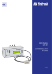
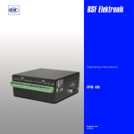
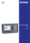
USER MANUAL APG 801 1 VPP ELECTRONIC SIGNAL TEST/ SET-UP BOX 10/2012 CONTENTS 1. General Description................................................................................................................................................................................................. 3 2. Function Elements............................................................................................................................................................................................... 3, 4 3. Pin Assignments...................................................................................................................................................................................................... 5 4.Commisioning ......................................................................................................................................................................................................... 5 5. Switch Track Signals .............................................................................................................................................................................................. 6 6. Controlling the Linear Encoder Signals with the Graphic Display................................................................................................................... 6 6.1 Counting Signals............................................................................................................................................................................................... 6 6.2 Reference Pulse ................................................................................................................................................................................................ 7 7. Controlling Encoder Signals with the Oscilloscope........................................................................................................................................... 8 . 02 www.rsf.at 1.GENERAL DESCRIPTION The APG 801 1 Vpp controls the output signal from 1 Vpp linear encoders with: Standard RI Wide (long) RI (MS 80, MS 82) It is possible to monitor the size and quality of the counting signals and the width and position of the RI. The measurement values are displayed on a LC Display. The output signals of the linked linear encoder can also be monitored through BNC female connectors using an oscilloscope. 2. FUNCTIONAL ELEMENTS 03 Linear Encoder Input: Linear encoder connection. An appropriate adaptor cable must be used depending on the version. For configuration see Section 3. Power Cube Transformer Connection: An external power cube transformer (5 V/1 A, stabilised) is required (included in delivery) to supply the APG 801 1 Vpp and the linked linear encoder N.B. Power consumption is about 1 A for 5 V. BNC female Connectors: Control the linear encoder signals using an oscilloscope LCD Graphic Display: The size and quality of the counting signals and the position and width of the reference pulse are displayed. Indicator LEDs Power Supply: Lights up when +5 V power supply is present. Indicator LEDs BNC Boxes: This LED lights up if the 2.5 V reference voltage is applied to the BNC female connectors. Indicator LED Switch Track Signal: These LEDs indicate the switching status of the linear encoder switch track signals. Switch 1: This switch is used to select the RI type of the linear encoder to be monitored. Switch 2: This switch is used in sine mode to switch the reference voltage Uref (2.5 V) to the BNC connectors. 04 Linear encoders with long RI (MS 80, MS 82) can be monitored.. All linear encoders with Standard RI and 1 Vpp signals can be monitored. www.rsf.at 3. PIN ASSIGNMENTS 1515 pinpin D-SUB female connector D-SUB Connector female Pin Signal 1 2 3 4 5 6 7 8 9 10 11 12 13 14 15 Test* nc nc RI A2 A1 nc +5 V 0V S1 S2 RI A2 A1 nc Test* = directly to +5 V 4. COMMISSIONING The linear encoder to be monitored is connected to the APG 801 1 Vpp linear encoder input. An appropriate adaptor cable must be used depending on the version. Connect the external power cube transformer to the testing device. Check the polarity of the low voltage plug when doing this 0V +5 V A power cube transformer with a stabilised output voltage of 5 V/1 A must be used. Select the linear encoder to be monitored using switch 1. Long RI: MS 80, MS 82 Standard RI: all other linear encoders with 1 Vpp output signals Shift switch 2 into " " position (sine mode). Switch on power cube transformer. 05 5. SWITCH TRACK SIGNALS The switching status of S1 and S2 will each be displayed by a separate LED. Switch track signal output High = LED lights up. Switch track signal output Low = LED does not light up. 6. CONTROLLING THE LINEAR ENCODER SIGNALS WITH THE GRAPHIC DISPLAY After the supply voltage has been applied, a 2 second welcome graphic appears on the graphic display showing the status of the integral software version. It then switches to measurement mode. The display is divided into 2 sections. In the top half the size and quality of the counting signals are displayed. In the bottom half the width and position of the RI signal. BarTop for display bar counting signals Framework for box Bounding counting signals track signals track signals BarDisplay for bar referencepulse reference pulse Framework forbox Bounding referencepulse reference pulse Measuring area Measurement area Referencepulse Reference pulsemark display 6.1. Counting Signals The width of the display bar depends upon the sum of the signal deviation (amplitude ratio, phase deviation and offset). The position of the bar provides information on signal amplitude. At optimum mounting, the display bar must be within the bounding box. Minimum Minimum 0,8V 0.8 Vpp pp pp 11VVpp Maximum Maximum 1,2V pp 1.2 Vpp For signal amplitudes of less than 6 μA, there is an automatic switch over of the measurement area to a smaller measurement area. For signal amplitudes of more than 16 μA, the error message “SIGNALS TOO LARGE” will fade into the display. 06 www.rsf.at 6.2. Reference Pulse The position of switch 1 is crucial to displaying the RI in the graphic display (long RI / Standard RI). The display of the display bar depends on the type selected. Traversing the RI mark makes the “RI” display in the lower right hand corner flash. 6.2.1 Encoder with Standard RI RI width: The length of the bar indicates the width of the RI signal. RI position: The RI position is indicated by the position of the bar. 135° ≙ 360° At optimum mounting, the bar must remain within the bounding box. 6.2.2 Linear Encoder with long RI: MS 80, MS 82 RI witdh: The actual width of the reference pulse for the particular linear encoder MS 80, MS 82 cannot be shown in the display. It will, however, be possible to see whether the width is within specified limits. ideal too narrow too wide RI position: The bar which is generated to show the RI width is always displayed at 135° (±2 pixels). 07 7. CONTROLLING THE LINEAR ENCODER SIGNALS WITH THE OSCILLOSCOPE The linear encoder signals can be controlled at the BNC-connectors with an oscilloscope. At optimum mounting, the signals must fulfill the requirements of the relevant signal specification. Shift switch 2 into “Uref” position. The reference voltage on the BNC connector will be output as Uref. Set the oscilloscope input sensitivity to 0.5 V/div on all channels and set the Y-deflections to screen centre. Shift switch 2 into “ ” position. The current signals with voltage conversion are output at the BNC connectors. Connector Signal 08 BNC-A BNC-B BNC-C A1 A2 RIa DISTRIBUTION CONTACTS AUSTRIA Corporate Head Quarters RSF Elektronik Ges.m.b.H. A-5121 Tarsdorf 93 +43 62 78 81 92-0 +43 62 78 81 92-79 e-mail: [email protected] internet: www.rsf.at FRANCE HEIDENHAIN FRANCE sarl 2 Avenue de la Christallerie 92310 Sèvres +33 1 41 14 30 00 +33 1 41 14 30 30 e-mail: [email protected] internet: www.heidenhain.fr GREAT BRITAIN HEIDENHAIN (GB) Ltd. 200 London Road Burgess Hill West Sussex RH15 9RD +44 1444 247711 +44 1444 870024 e-mail: [email protected] internet: www.heidenhain.co.uk ITALY HEIDENHAIN ITALIANA S.r.l. Via Asiago, 14 20128 Milano (MI) +39 02 27075-1 +39 02 27075-210 e-mail: [email protected] internet: www.heidenhain.it NETHERLANDS HEIDENHAIN NEDERLAND B.V. Copernicuslaan 34 6710 BB EDE + 31 318 58 18 00 + 31 318 58 18 70 e-mail: [email protected] internet: www.heidenhain.nl SWEDEN HEIDENHAIN Scandinavia AB Storsätragränd 5 SE-12739 Skärholmen +46 8 531 933 50 +46 8 531 933 77 e-mail: [email protected] internet: www.heidenhain.se SWITZERLAND RSF Elektronik (Schweiz) AG Vieristrasse 14 CH-8603 Schwerzenbach +41 44 955 10 50 +41 44 955 10 51 e-mail: [email protected] internet: www.rsf.ch CHINA RSF Elektronik Tian Wei San Jie, Area A, Beijing Tianzhu Airport Industrial Zone Shunyi District, 101312 Beijing P.R. China +86 10 80 42 02 88 +86 10 80 42 02 90 e-mail: [email protected] internet: www.rsf.cn JAPAN HEIDENHAIN K.K. Hulic Kojimachi Bldg., 9F 3-2 Kojimachi, Chiyoda-ku Tokyo, 102-0083 +81 3 3234 7781 +81 3 3262 2539 e-mail: [email protected] internet: www.heidenhain.co.jp KOREA HEIDENHAIN LTD. 202 Namsung Plaza, 9th Ace Techno Tower, 130, Digital-Ro, Geumcheon-Gu, Seoul, Korea 153-782 +82 2 20 28 74 30 e-mail: [email protected] internet: www.rsf.co.kr USA HEIDENHAIN CORPORATION 333 East State Parkway Schaumburg, IL 60173-5337 +1 847 490 11 91 e-mail: [email protected] internet: www.rsf.net Date 10/2012 Art.Nr. 800743-21 Doc.Nr. D800743-01-A-21 Technical adjustments in reserve! Ges.m.b.H. A-5121 Tarsdorf Linear Encoders Cable Systems Precision Graduations Digital Readouts +43 (0)6278 / 8192-0 FAX Certified acc. to DIN EN ISO 9001 DIN EN ISO 14001 +43 (0)6278 / 8192-79 e-mail: [email protected] internet: www.rsf.at