1
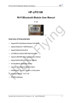
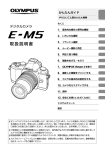
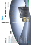
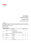
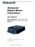
User Manual EPC-CM3 CANOPEN GK800 series High Performance AC Motor Drives Dedicated Table of Contents Chapter 1 Instruction of Dedicated Functions ...................................................................... 1 Chapter 2 Modification of Hardware ....................................................................................... 3 Chapter 3 Simple List of Dedicated Functions ..................................................................... 4 Chapter 4 Specification of Dedicated Functions .................................................................. 5 Chapter 5 Overview of CANopen ............................................................................................ 6 5.1 Core of CANopen Protocol ................................................................................................. 6 5.2 CANopen Communication Protocol ................................................................................... 8 5.2.1 NMT (Network Management Object) ...................................................................... 8 5.2.2 SDO (Service Data Objects).................................................................................... 9 5.2.3 PDO (Process Data Object) .................................................................................. 10 5.2.4 EMCY (Emergency Object) ................................................................................... 11 5.2.5 Node/Life Guard or Heartbeat ............................................................................... 11 5.3 Introduction to DSP-402 Motion Control .......................................................................... 13 5.3.1 Overall Architecture ............................................................................................... 13 5.3.2 Driver Statemachine .............................................................................................. 14 5.3.3 State Transition of Driver ....................................................................................... 15 5.3.4 Modes of Operation ............................................................................................... 17 5.3.5 Device Control........................................................................................................ 18 5.3.6 Status Word ............................................................................................................ 19 Chapter 6 CANopen Communication and Inverter Control ................................................. 22 6.1 Operation Steps ................................................................................................................ 22 6.2 Operation Mode ................................................................................................................ 22 6.2.1 Velocity Mode......................................................................................................... 23 6.2.2 Torque Mode (Profile Torque Mode) ..................................................................... 23 6.2.3 Simple Feed Mode ................................................................................................. 24 6.2.4 Motor Spindle Orientation Mode............................................................................ 24 6.3 PDO Mapping.................................................................................................................... 25 6.4 LED Indicator Lights ......................................................................................................... 26 Appendix 1: Object Dictionary (Factory Default)................................................................... 27 Appendix 2: Fault Code............................................................................................................. 37 EPC-CM3 User Manual Chapter 1 Instruction of Dedicated Functions Chapter 1 Instruction of Dedicated Functions The dedicated inbuilt CANOPEN functions of GK800- CANOPEN are to provide more rapid control mode for the external control. CAN communication is adopted by CANopen in the physical layer, which has the following advantages and characteristics: ultra-high utilization rate of bus, high-speed data transmission, reliable error handling, and automatic data retransmission after the destruction and so on. CANopen is an upper-layer protocol based on CAN and mainly designed for the following communication objects: PDO (Process Data Objects), Service Data Objects, Time Stamp, SYNC Message, Emergency Message and Network Management Data which includes NMT Messages and Error Control Messages. Protocol Specifications: CAN2.0A CANopen DS301 V4.02 CANopen DS402 V2.0 Support Services 8 pairs of PDO(Process Data Objects) TPDO1~TPDO8 RPDO1~RPDO8 SDO(Service Data Objects) Initiate SDO Download Initiate SDO Upload SYNC Message Emergency Message Network Management Data NMT Mode Control NMT Error Control Node Guarding Protocol Heartbeat Protocol Heartbeat Consumer Support Modes DS402 Part Velocity Mode, 2 Profile Torque Mode, 4 Self-defined Part Simple Feed Mode, -1 Motor Spindle Orientated Mode, -7 1 Chapter 1 Instruction of Dedicated Functions EPC-CM3 User Manual Unsupported Services Time Stamp Downloading SDO Segment Uploading SDO Segment Heartbeat Producer The dedicated Manual should be used together with the User Manual for GK800 Series High Performance AC Motor Drives. 2 EPC-CM3 User Manual Chapter 2 Modification of Hardware Chapter 2 Modification of Hardware Communication expanded card (EPC-CM3) dedicated for CANopen should be provided with GK800 series AC motor drives. The definitions of CAN terminals of EPC-CM3 are as shown in Fig. 2-1 and Table1. Fig. 2-1 Definitions of CAN Terminals Table 2-1 Definition and Instruction of Pins Terminal 1 2 3 4 Definition VCC DGND CAN+ CAN- Decription Power supply terminal /5V Ground terminal/0V CAN_H bus line (dominant high) CAN_L bus line (dominant low) 3 Chapter 3 Simple List of Dedicated Functions EPC-CM3 User Manual Chapter 3 Simple List of Dedicated Functions Param. H1-00 Name Node address of CANopen H1-01 Communication speed of CANopen H1-02 H1-03 H1-04 Initial state options of CANopen Parameter transmission Protective action of internal communication Scope 1~127 0: 10 kbps 1: 20 kbps 2: 50 kbps 3: 125 kbps 4: 250 kbps 5: 500 kbps 6: 1000 kbps 0~1 0~1 0~1 4 Factory Default 1 Attr × 5 × 0 0 × × 0 × EPC-CM3 User Manual Chapter 4 Specification of Dedicated Functions Chapter 4 Specification of Dedicated Functions H1-00 Node Address of CANopen Range: 1~127 Factory Default: 1 Range: 0~6 Factory Default: 5 Range: 0~1 Factory Default: 0 Node Address of CANopen 1~127: Local Node-ID H1-01 Communication Speed of CANopen Communication Speed of CANopen * 0: 10 Kbps 1: 20 Kbps 2: 50 Kbps 3: 125 Kbps 4: 250 Kbps 5: 500 Kbps 6: 1000 Kbps H1-02 Initial State Options of CANopen Initial State Options of CANopen 0: Be subject to CANopen standard After the boot-up message is sent, the node enters to the PRE-OPERATIONAL state. 1: Automatically enter OPERATIONAL state After the boot-up message is sent, the node enters to the OPERATIONAL state. H1-03 Parameter Transmission Range: 0~1 Factory Default: 0 Parameter Transmission 0: No action 1: Parameter Retransmission The parameters can be uploaded to the expansion card through the internal communication. Generally, after the modification of some functional parameters via the keypad and the setting of H1-03=1, the latest parameters can be uploaded without power off. H1-04 Protective Action of Internal Communication Range: 0~1 Protective Action of Internal Communication 0: Fault action and free stop 1: Shielding the fault 5 Factory Default: 0 Chapter 5 Overview of CANopen EPC-CM3 User Manual Chapter 5 Overview of CANopen CANopen is an upper-layer protocol based on the CAN, and is a control network function to make the equipment achieve the purpose of the motion control, just acting as the general management system. CANopen 301 standard (Version 4.02) is EN50325-4. The specifications of CANopen contain the overview of the application layer and communication (CiA DS301), architecture of the programmable units (CiA DS302), cables and connectors (CiADS303-1) as well as SI units and text representations (CiA DS303-2). Bus Fig. 5-1 Location Block Diagram of CAN and CANopen Standard in OSI Network Model 5.1 Core of CANopen Protocol The core of CANopen protocol is shown as follows: 1) The COB-ID(Communication Object Identifiers) are defined with CAN identifier segments (ID10~ID0); 2) The OD (OBJECT DICTIONARY) of equipment is used. Each node in the CANopen network has an object dictionary which contains all parameters describing the behaviors of this device and its network, namely all the parameters defined by the CANopen specifications which are saved in OD (DS301- communication norm; DS4XXequipment specification), and provides sufficient space (The object dictionary of a node ranges from 1000 H to 9 FFFH) to the product parameters of the users. The parameters in OD are addressed via 16 bit index and 8 bit sub-index and can be be the data of 1 ~ 4 bytes, so the 6 EPC-CM3 User Manual Chapter 5 Overview of CANopen largest space occupied by OD is 64K* 256 * 4 = 64MBYTES in theory. COB - ID includes the FUNCTION segment and address segment (the NODE ID), and 127 stations can be defined in all. These stations are integrated in all kind of communication messages with the COB ID values as the contents, and the IDs of the CANopen communication messages can be expressed in the following formula. COB-ID = FUNCTION+NODE-ID The Node-ID shall be defined by the system integrators, for example, it can be set via the toggle switch. The scope of Node - ID is 1 ~ 127(“0” is not permitted to be used). On the master station, the function segment refers to the operation contents of the master station over the slave station; the address segment (Node ID) the address of the slave stations operated (station number); on the slave station, the function section shows the response of the slave station to the master station, while the address segment refers to the address of the response slave station (station number). Four types of communication messages are assigned by COB ID as specified in the CANopen communication models, and its scope is 000 h ~ 7 FFH. The lower the value is, the higher the priority will be. ID10 ID7 ID6 ID0 Function Node-ID (1~127 sites) Fig. 5-2 Composition of COB-ID The COB-IB definitions for the broadcast objects of master/slave connected subnetwork predefined by CANopen and its equal objects are as shown in Table 5-1 and Table 5-2. Table 5-1 Broadcast Objects of Master/Slave Connected Subnetwork Predefined by CANopen Broadcast Objects of Master/Slave Connected Subnetwork Predefined by CANopen Function Code Index of Communication Object COB-ID (ID bits10~7) Parameters in OD NMT 0000 000H SYNC 0001 080H 1005H,1006H,1007H TIME SSTAMP 0010 100H 1012H,1013H 7 Chapter 5 Overview of CANopen EPC-CM3 User Manual 5.2 CANopen Communication Protocol The CANopen communication protocol includes the following services: NMT (Network Management Object) SDO (Service Data Objects) PDO (Process Data Object) EMCY (Emergency Object) Node/Life Guard or Heartbeat 5.2.1 NMT (Network Management Object) The network management message- NMT provides the NMT service by following the master station/slave station architecture. There is only one master station which can be equipped with many slave stations in this architecture. All CANopen nodes have their own NMT states, while the master station can control the states of the slave stations via the NMT messages, with the state flow chart shown as follows: Fig. 5-3 State Transition Diagram of Minimized Boot-Up Nodes for CANopen Table 5-2 Opreands in States Initialization NMT a Node Guard b SDO c EMCY d PDO e Boot-up f ○ Pre-Operational State Operational State Stop State ○ ○ ○ ○ ○ ○ ○ ○ ○ ○ ○ 8 EPC-CM3 User Manual Chapter 5 Overview of CANopen Table 5-3 State Transition NMT Command Words Name of Command Command Words (HEX) 1 Start Remote Node 01 2 Stop Remote Node 02 3 Enter Pre-Operational State 80 4 Reset Node 81 5 Reset Communication 82 After the device initialization is over, the system enters to the pre-operational state 6 automatically and then sends the boot-up message. The NMTprotocol is shown as follows: 5.2.2 SDO (Service Data Objects) The SDO (Service Data Objects) are used on both ends, namely clients/servers, and each have permission for the object dictionary. A SDO message contains a set of COB - ID (Required SDO and repsonsive SDO), can be accessible between two nodes. SDO can transfer the data of any size, but once the data size is more than 4 bytes, then the segment transmission means should be used, and the last segment should consist of a finish instruction. The object dictionary is the group object of CANopen node, and each node has its own object dictionary.The object dictionary contains many parameters which describe its supporting parameter properties and values. The SDO is accessed by means of indexes and sub-indexes. Each object has a single index value, but may have multiple sub-indexes if necessary.The SDO requirement and response message architecture request is shown as follows: Table 5-4 Definitions of SDO Commands Byte0 7 6 5 Command Regional Client 0 0 1 Downloading Server 0 1 1 Regional Client 0 1 0 Uploading Server 0 1 0 Stop Client 1 0 0 Transmission Server 1 0 0 Name 4 3 - N N - 2 - 1 0 E E - S S - Byte1 Byte2 Byte3 Byte4 Byte5 Byte6 Byte7 Index Index Index Data Data Data Data L H Sub LL LH HL HH N: Not used number of bytes, E: Common (0) / Send (1), S: Symbol of data size 9 Chapter 5 Overview of CANopen 5.2.3 EPC-CM3 User Manual PDO (Process Data Object) The PDO (Process Data Objects) are used on producers/consumers, and each network node can listen to messages from the transmission nodes, and also judge whether to deal with them or not after receipt. The PDO data transfer can be finished in one-to-one or one-to-many manner. The size of the data to be transmitted shall be within the range of 1~ 8 bytes (for example, a PDO can transfer up to 64 digital I/O values or 4 AD values of 16 bits). The PDO communication shall not be subject to any agreement. The PDO data contents are only defined by its CAN ID, assuming that the data contents of this PDO are known by producers and consumers. The contents of the PDO messages are predefined (or configured in the process of network startup), and the mapping of the application objects to the PDO is described in the device object dictionary. If the devices (producers and consumers) support the variable PDO mapping, then the PDO mapping parameters can be configured with the SDO messages. Every PDO message contains the transmission PDO (TPDO) and receiving PDO (RPDO) messages, and its transmission modes are defined in the PDO communication parameter index (The first group of PDO messages received is located in 1400 h index, and the first group of the PDO messages sent is located in the index 1800 h). The transmission modes are listed in the following table. Table 5-5 Definition of PDO TransmissionType Transmission Type 0 1-240 241-251 252 253 Conditions to Trigger PDO (B=both needed O=one or both) SYNC RTR Event B B O B B O - 254 - O O 255 - O O NOTE: PDOs. PDO Transmission Synchro, non-cyclical Synchro, cyclical Reserved Synchro, after RTR Asynchronous, after RTR Asynchronous, specific events related to manufacturers Asynchronous, specific events related to equipement sub-protocol SYNC – Receive the SYNC-object. RTR -Receive the remote frame. Event –For example, value change or interruption of timer. Transmission Type: For 1~240,the figure stands for the value of the SYNC object between For example, provided that the second map of the TPDO is as shown as follows (it is described with the object dictionary index 1A01H in CANopen). Object1A01H : Serieal No. 0 1 2 Second TPDO Value 2 60410010H 60610008H Map Meanings Two objects mapped to PDO Object, 6041H;sub-index, 00H,consisting of 16 bits Object, 6061H;sub-index, 00H,consisting of 8 bits In the definitions of the equipment sub-protocol (CiA DSP - 402) for CANopen Drives and Motion Control module, the one with the object of 6041 H and the sub-index of 00 H refers to the Status Word, while the one with the object of 6061 H and the sub-index of 00H refers to Modes of Operation Display. If the PDO message issent (it may be triggered in ways of the input change, timer interruption or remote request frame and so on, and its transmission type is consistent to that of the PDO; it can be found in the sub-index 2 of the object 1801H), then the message consists of 3 bytes of data, with the format shown as follows: 10 EPC-CM3 User Manual PDO-producer PDO-consumer(s) COB-ID Byte0 280H+Node-ID Status Word-L Chapter 5 Overview of CANopen Byte1 Status Word-H Byte2 Modes Of Operation Display The PDO content can be changed by changing the content of the object 1 A01H (if the node support (variable PDO mapping)). Please note that the LSB (Little Endian) of the multi-byte shall be always sent first in the CANopen. The data more than 8 bytes are not allowed to be mapped to a PDO. MPDO multiplexor (PDO), defined in the CANopen Application Layer and the Communication Profile (CiA DS 301 V 4.02), allows a PDO to transmit a large number of variables through the sources contained in the data bytes ofthe message or the indexes and sub-indexes in the destination nodes- ID and OD. 5.2.4 EMCY (Emergency Object) When there is an internal error in the hardware, an emergency object will be triggered. The emergency object is transmitted only when there is an error in the hardware, and is used as a false alarm interrupt message. The emergency object is 8 bytes of data and is expressed as follows: Table 5-6 Definition of EMCYObject Byte 0 1 Content Emergency Error Code 2 3 4 5 6 7 Error register Manufacturer specific Error Field (Object 1001H) The definition of the emergency object message is shown in Appedix 2 CANopen Fault Codes. 5.2.5 Node/Life Guard or Heartbeat The MNT master node can check the current state of each node through the node protection service which is significant especially when these nodes send no data. The process that the NMT-Master mode sends the remote frame (no data) is shown as follows: NMT-MasterNMT-Slave COB-ID 700H+Node_ID The NMT-Slave nodes send the following message response: NMT-Master NMT-Slave COB-ID Byte0 700H+Node_ID Bit 7: toggle; Bit6-0: state The data part contains a toggle bit (bit 7) which should be alternatively set to “0” or “1” while the node makes a protective response. The toggle bit is set to “0” at the first node protective request. Bits 0~6 mean the node states and can be expressed with the values intable 5-7. 11 Chapter 5 Overview of CANopen EPC-CM3 User Manual Table 5-7 Definition of NMT-Slave Node States Value State 0 Initialising 1 Disconnected * 2 Connecting * 3 Preparing * 4 Stopped 5 Operational 127 Pre-operational NOTE: The states marked with “*” are only provided by the nodes supporting the extendable boot-up function. Please note that State 0 shall not appear in the node protective response, because a node shall not respond to the node protective message in this state. As well, a node can be configured to the periodic Heartbeat message. Heartbeat Producer Consumer(s) COB-ID Byte0 700H+Node_ID State The states can be shown as in the table below: Table 5-8 Definition of NMT-Slave Node States Value State 0 Boot-up 4 Stopping 5 Operational 127 Pre-operational After a Heartbeat node is started, its boot-up message is the first Heartbeat message.The heartbeat consumers are usually NMT Master nodes which shall set a timeout value for each heartbeat node so that the corresponding action will be taken when the timeout occurrs. A Node can not be able to support both the Node Guarding and Heartbeat protocols at the same time. 12 EPC-CM3 User Manual Chapter 5 Overview of CANopen 5.3 Introduction to DSP-402 Motion Control 5.3.1 Overall Architecture Fig 3 Diagram of Overall Architecture 13 Chapter 5 Overview of CANopen 5.3.2 EPC-CM3 User Manual Driver Statemachine Unlike most other equipment sub-protocols, the driver sub-protocol gives an accurate description to its characteristics. This sub-protocol not only defines the operational mode and the corresponding parameter of the driver, but also defines a statemachine used to control the driver. The statemachine controls the driver via command word (Index 6040 H), as shown in Figure 5. All the states in the statemachine are indicataed by status words (Index 6041H). The state of the driver is changed only through some instructions on Object 6040 H or internal events. For example, only when the driver is in allowable running state, can the point-to-point movement be allowed to trigger. Fig 5 State Transition Diagram As shown in Fig 5, the driver has the following states: Not Ready to Switch On Low-voltage power supply of the controller is switched on (such as ±15V, 5V); The driver is being initialized and has carried out the internal self-check; If there is a braking device, then it is also activated; Driver functions disabled Switch On Disabled The driver has been initialized; Driver parameters need to be set; Driver parameters changeable; 14 EPC-CM3 User Manual Chapter 5 Overview of CANopen No high voltage supplied to the driver (such as for the security considerations or other reasons); Driver functions disabled Ready to Switch On The high voltage is supplied to the driver; The power amplifier gets ready to work; Driver parameters changeable; Driver functions disabled Operation Enable No error; The drive function is enabled aiming at a special operational mode, and the motor is started; The dynamic parameter settings for the driver can be done in the way of on-the-fly. Quick Stop Active Driver parameters changeable; Emergency stop function is active; The driver function is active and simultaneously the motor is started. NOTE: If “Quick-Stop-Option-Code” is “5” (Stay in Quick-Stop), then the Quick-Stop-State is kept and it can be switched to“Operation Enable” via the“Enable Operation” command. Fault Reaction Active Driver parameters changeable; There is nonfatal fault in the driver; Emergency stop function is conducted; The driver function is active and simultaneously the motor is started. Fault Driver parameters changeable; The driver goes wrong; Driver functions disabled 5.3.3 State Transition of Driver The state transition reason includes the internal events of the driver or the control word command from the master control. State Transition 0: StartupNot Ready to Switch On Event: Reset Function: Self-check and/or initialization of driver State Transition 1: Not Ready to Switch On Switch On Disabled Event: Successful self-check and/or initialization of driver Function: To activate communication and process data monitoring State Transition 2: Switch On Disabled Ready to Switch On Event: Receiving a “Shutdown”command from the master control Function: no State Transition 3: Ready to Switch On Switched On Event: Receiving a “Switch On”command from the master control Function: To swtich on the power supply State Transition 4: Switched On Operation Enable 15 Chapter 5 Overview of CANopen EPC-CM3 User Manual Event: Receiving a “Enable Operation”command from the master control Function: To enable the driver function State Transition 5: Operation Enable Switched On Event: Receiving a “Disable Operation” command from the master control Function: To disable the operation of driver State Transition 6: Switched On Ready to Switch On Event: Receiving a “Shutdown”command from the master control Function: To switch off the power supply of driver State Transition 7: Ready to Switch On Switch On Disable Event: Receiving a “Quick Stop” command from the master control Function: No State Transition 8: Operation Enable Ready to Switch On Event: Receiving a “Shutdown”command from the master control Function: The power supply is cut off at once and the motor stops automatically if there is no brake State Transition 9: Operation Enable Switch On Disalbe Event: Receiving a “Disable Voltage” command from the master control Function: The high-voltage power supply is cut off at once and the motor stops automatically if there is no brake State Transition 10: Switched On Switch On Disalbe Event: Receiving a “Disable Voltage” command from the master control Function: The power supply is cut off at once and the motor stops automatically if there is no brake State Transition 11: Operation Enable Quick Stop Active Event: Receiving a “Quick Stop” command from the master control Function: To execuate an emergency stop command State Transition 12: Quick Stop Active Switch On Disabled Event: “Quick Stop” is completed or a “Quick Stop” command is received from the master control Function: To switch off the power supply State Transition 13: All StatesFault Reaction Active Event: Critical fault in the driver Function: Execute the corresponding fault response State Transition 14: Fault Reaction Active Fault Event: Fault response over Function: Driver function disabled, power supply shut off possibly State Transition 15: Fault Switch On Disabled Event: Receiving a “Fault Reset” command from the master control Function: If there is a fault, the current fault of the driver is reset; later, the master control will clear off the “Fault Reset” bit in the control work and the driver is not in “Fault” state. State Transition 16: Quick Stop Active Operation Enable Event: Receiving an “Enable Operation” command from the master control. For this transition, Quick-Stop-Option-Code should be 5, 6, 7 or 8. Function: Driver function enabled 16 EPC-CM3 User Manual Chapter 5 Overview of CANopen The methods for interrupting the state transition are listed in Table 5-9. Table 5-9 Objects of Option Codes for Interrupting State Transition Index Name State Transition 605BH Shutdown Option Code 8 605CH Disable Operation Option Code 5 605AH Quick Stop Option Code 11 605EH Fault Reaction Option Code 13 5.3.4 Modes of Operation The behaviors of the driver are defined by the operation modes (Modes of Operation, Index 6060H, Write Only; Modes of Operation Display, Index 6061 H, Read Only), and the standard modes defined are shown as follows. Please refer to the CiA Specification DSP – 402 for the details of operation modes. Standard Position Mode (1,Profile Position Mode) In this position mode of the driver, the following parameters can be set, including the speed, position, acceleration, limits as well as the displacement according to the desired trajectory. Velocity Mode (2,Velocity Mode) In this mode, the speed is controlled by the inverter, and there are speed limitation and slope function. This mode is generally used when there is no speed sensor. Standard Velocity Mode (3,Profile Velocity Mode) The speed of the driver is controlled in the standard velocity mode without he designated location, and this mode supports the limit function and the track production. Standard Torque Mode (4,Profile Torque Mode) This torque control defines all the parameters related to the torque. Homing Mode (6,Homing Mode) This mode defines several methods for finding original locations (also defines the reference points, data and zero). Interpolated Position Mode (7, Interpolated Position Mode) The mode describes the single axis interpolation and the travel of spatial linkage axistime interpolation. Synchronous machines and interpolation data cache are included. There are many different adjusters in the drivers, and different parameters should be used for different algorithms for each adjuster. Coupled with the diverse technical solutions, all the adjusters can not be defined in a standardized way. If the parameters of the adjuster should be set through the network, then the objects defined by the manufacturers must be used. 17 Chapter 5 Overview of CANopen 5.3.5 EPC-CM3 User Manual Device Control The Device Control (Index 6040H) can start or stop the driver and commands specified in several modes. These commands are execuated by the statemachine. The meanings of the control words are shown in Table 10. MSB Bit Bit 15 14 Bit 13 Bit 12 Bit 14 Bit 10 Bit 9 Bit 8 | LSB Bit Bit 7 6 Bit 5 Bit 4 Bit 3 Bit 2 Bit 1 Bit 0 Table 5-10 Bit Definition of Control Words Name Compulsive or Bit Not 0 Switch On √ 1 Disable Voltage √ 2 Quick Stop √ 3 Enable Operation √ 4 Operation Mode Specific 5 Operation Mode Specific 6 Operation Mode Specific 7 Reset Fault √ 8 Halt 9 Reserved 10 Reserved 11 Manufacturer Specific 12 Manufacturer Specific 13 Manufacturer Specific 14 Manufacturer Specific 15 Manufacturer Specific The commands triggering the device control in the definition of the control word bit are listed in Table 5-11. Table 5-11 Device Control Command Control Bit7 Bit3 Word Fault Enable Command Reset Operation Shutdown 0 × Switch On 0 × Disable 0 × Voltage Quick Stop 0 × Disable 0 0 Operation Enable 0 1 Operation Fault Reset × Bit2 Bit1 Bit0 Quick Stop 1 1 Disable Voltage 1 1 Switch On 0 1 × 0 × 7,9,10,12 0 1 × 7,10,11 1 1 1 5 1 1 1 4,16 × × × 15 The bit definitions in modes (Bit 4~ Bit 6) are shown in Table 5-12 18 Transition of Statemachine 2,6,8 3 EPC-CM3 User Manual Chapter 5 Overview of CANopen Table 5-12 “Mode specific” Bits in Control Word Mode Bit Velocity Standard Standard Stanard Homing Interpolated Mode Position Mode Velocity Mode Torque Mode Mode Position Mode RFG New position Reserved Reserved Homing Enabled position 4 Disabled point operation interpolation RFG Stop Change Reserved Reserved Reserved Reserved 5 position at once RFG for 0: Absolute Reserved Reserved Reserved Reserved zero motion 6 1: Relative motion 8 Pause Pause Pause Pause Pause Pause RFG: Running up Frequency Generator Pause: To interrupt the operation of the driver and then continue to run after releasing. 5.3.6 Status Word Status word (Status Word, Index 6041H) refers to the current status of the driver and is always mapped to the second byte of the actual message, and the bit definitions of the status words are shown in the table below. MSB Bit Bit 15 14 Bit 13 Bit 12 Bit 14 Bit 10 Bit 9 Bit 8 | LSB Bit Bit 7 6 Table 5-13 Bit Definitions of Status Words Name Compulsive or Bit Not 0 Ready to Switch On √ 1 Switched On √ 2 Operation Enabled √ 3 Fault √ 4 Voltage Disabled √ 5 Quick Stop √ 6 Switch On Disabled √ 7 Warning 8 Manufacturer Specific 9 Remote √ 10 Target Reached √ 11 Internal Limit Active √ 12 Operation Mode Specific 13 Operation Mode Specific 14 Manufacturer Specific 15 Manufacturer Specific 19 Bit 5 Bit 4 Bit 3 Bit 2 Bit 1 Bit 0 Chapter 5 Overview of CANopen EPC-CM3 User Manual The bit meanings of the state are shown in Table 5-14. Table 5-14 Bit Meanings in States Bit6 Bit5 State Switch On Quick Disable Stop Not Ready to 0 × Switch On Switch On 1 × Disabled Ready to 0 1 Switch On Switched On 0 1 Operation 0 1 Enabled Fault 0 × Fault Reaction 0 × Active Quick Stop 0 0 Active Bit3 Fault Bit2 Operation Enable Bit1 Switched On Bit0 Ready to Switch On 0 0 0 0 0 0 0 0 0 0 0 1 0 0 1 1 0 1 1 1 1 1 1 1 1 1 1 1 0 1 1 1 Bit 4: Voltage Disable When the Voltage Disable bit is in zero clearing state, it means that the Disable Voltage request has come into effect. Bit 5: Quick Stop Upon resetting, this bit means that the driver responds to the Quick Stop request, and Bit 0, 1 and 2 in status word must be set to be “1” in order to restore the driver. Bit7: Warning This bit refers to a warning of the driver, which means no error, but it should stand for a state, such as the temperature limitation, operation refusal. At this moment, the status of the driver does not change. The reason for the warning can be found out through reading fault codes, and this bit can be set and reset by the equipment. Bit8, Bit14 and Bit15: Manufacturer Specific This bit can be used for the user-defined function of the driver manufacturer. Bit9: Remote If Bit 9 is set, then the parameter can be modified via CAN network and the driver can receive the control command; if this bit is reset, then the driver executes the local command, and cannot execute the remote command. The message sent by the driver includes the local actual value of the driver, such as Position Actual Value. In the local mode, the driver can also receive the SDO command. Bit10 Target Reached If Bit 10 is set for the driver, then it means that a setting point is reached (torque, velocity, position, etc.), and this bit can be changed through the change of a software target value. When the emergency stop operation is over and the driver pauses, if Quickstop Option Code is 5, 6, 7or 8,then this bit should be set. If the pause takes effect and the driver pauses, this bit is also set. Bit 11: internal_limit_active This bit enabled means that the internal limitation of the driver is activated (such as the limitation of position range). 20 EPC-CM3 User Manual Chapter 5 Overview of CANopen Bit12 and Bit13 are assigned operating modes, as shown in the table below: Table 5-15 Indicating Bit of Operating Mode Profile Profile Velocity Bit Position Velocity Mode Mode Mode Reserved Setting point Velocity=0 12 confirmed Reserved Following Max. sliding 13 error error Profile Torque Mode Reserved Reserved Homing Mode Receiving at original point Finding original point error NOTE: All bits show the actual/current status of the driver, and no bit is locked. 21 Interpol. Position Mode Ip-Mode active Reserved Chapter 6 CANopen Communication and Inverter Control EPC-CM3 User Manual Chapter 6 CANopen Communication and Inverter Control 6.1 Operation Steps When the CANopen control inverter is required to be used, it should be configured according to the following steps: 1) Hardware wiring: Refer to the Hardware Wiring in Chapter Two. Connect CAN+ and CAN-. If the group networkcontrol is required, then the terminal resistants should be connected at two termnals if necessary. In fact, there is a toggle switch S2 for the terminal resistant selection on the CANopen control card, and the selective terminal resistant can be confirmed via “ON” or “OFF” button; 2) Parameter Settings of Driver a) To set the control mode (A0-09), motor parameter (Group d0) and coder parameter (Group d6, if the external coder is not used, then d6-00 should be still set to “1”). NOTE: The settings above are the parameters under the condition of “Motor 1”, namely A0-08=0 (Default); b) Parameter identification: Refer to Manual of GK800 Inverter in detail. It just refers to the identification of the first use of new motor; c) Driver reset or parameter setting H1-02=1, it is recommended to operate it after the driver is restarted; d) Setup of frequency main setting mode: b0-01=9,select the communication input; e) Setup of operation command setting mode: b1-00=2,select the communication control; f) Setup of electric/braking torque limit mode: d2-12=5 , d2-13=5 , select the communication setup; g) Setup of FWD/REV speed limit mode for torque control: d2-19=5,d2-20=5,select the communication setup; h) Setup of CANopen Station Number: The desired station number for H1-00 should be set within the range of 1~127. The driver should be restarted. i) Setup of CANopen baud rate: The baud rate for H1-01 should be set within the range of 0~6, with the specific value as shown in Chapter Four. The driver should be restarted. 3) CANopen Communication a) The register value of the corresponding index via the SDO protocol; b) NMT control enters the “Operational” state from the node; c) The inverter is controlled through using PDo to write in the control words and other parameters. 6.2 Operation Mode The driver mainly supports the following operation modes: Velocity Mode, 2 Profile Torque Mode, 4 Simple Feed Mode, -1 Motor Spindle Orientation Mode, -7. Simple feed mode and motor spindle orientation mode belong to the position control which is valid only when the "Closed-loop vector control (Index 2002 H, Function Code A0-09=3)". Therefore, the appropriate PG card should be chosen. The parameter settings and mode instruction in the position control mode are as shown in the Introduction part of Group F4 Position Control” in User Manual for GK800 Series High Performance AC Motor Drives. The common parameters are shown in Table 15 below, are set in the simple feed mode and motor spindle orientation mode as required. It is important to note that some parameters cannot be modified when the motor is running. For more detailed description of object, please refer to the parameter instruction of the function codes in function code, corresponding to the “Function Code” column in the Appendix “Object Dictioary”, in the User Manual for GK800 Series High Performance AC Motor Drives 22 EPC-CM3 User Manual Chapter 6 CANopen Communication and Inverter Control Table 5-16 Common Parameters of Position Control Object Function Name Code Index Sub-Index Length 2032 00 2 F4-01 Positioning completion width 2033 00 2 F4-02 Positioning completion time 2034 00 2 F4-03 Position loop gain Range 0~3000 Factory Default 10 0.000S~40.000S 0.200S 0.000~40.000 1.000 6.2.1 Velocity Mode The following parameters should be set in this mode: Table 5-17 Related Parameters in Velocity Mode Object Name Value Index Sub-Index Length 6060 00 1 Modes of Operation 2 6042 00 2 Target Velocity User defined 6046 01 4 Velocity Amount Min User defined 6046 02 4 Velocity Amount Max User defined 604F 00 4 Ramp Function Time User defined 6050 00 4 Slow Down Time User defined 6051 00 4 Quick Stop Time User defined Meanings Mode selection Target velocity Lower limit of velocity Upper limit of velocity Acceleration time Deceleration time Deceleration time of emergency stop 2005 01 2 Frequency MAX. User defined Max frequency setting 2013 01 2 Limt Torque Drive User defined Electric torque limit 2013 02 2 Limt Torque Break User defined Braking torque limit When the control word (Index 6040 H) is set to 007 FH, the motor starts to run according to the parameters mentioned in Table 17 above; set to 005 FH, the current speed will be locked. In the table, the maximum frequency setting (Index 2005, Sub-index 01) is in 0.01 Hz, namely “5000”for “50.00 Hz”; the torque limit (Index 2013, sub index01) setting is in 0.1%, namely “1000” for “100%”. The conversion between velocity and frequency can be realized through the following formula 120 = × In the formula above, —— Revolving speed in RPM ——Frequency in Hz ——Motor poles For examples: For the four-pole motor rotating in the forward direction at 30Hz, its revolving speed is: 30×120÷4=900(RPM) For the six-pole motor rotating in the reverse direction at 20Hz, its revolving speed is: 20×120÷6=-400(RPM) “-400” is transmitted in the complement form, so the value of Index 6042H is set to FE70H. 6.2.2 Torque Mode (Profile Torque Mode) The following parameters should be set in this mode: Table 5-18 Related Parameters inTorque Mode Object Name Index Sub-Index Length 23 Value Meanings Chapter 6 CANopen Communication and Inverter Control 6060 00 6071 00 6072 00 EPC-CM3 User Manual 1 2 2 Modes of Operation 4 Mode selection Target Torque User defined Target torque Max Torque User defined Max torque limit Torque Acceleration User defined Torque 2021 00 2 Deceleration Time acceleration/deceleration time 2022 01 2 Limt Speed Forward User defined Limit of forard rotating speed 2022 02 2 Limt Speed Reverse User defined Limit of reverse rotating speed When the control word (Index 6040 H) is set to 000 FH, the motor starts to run according to the parameters mentioned in Table 18 above and the “Target torque” is expressed with the relative percent of “Rated Torque” in 0.1%, namely “1000” for “100%”, “-1000” for “-100%”. The speed limit is in 0.01 Hz, namely “5000”for “50Hz”. The acceleration time is in 0.01s, namely “10” for “0.10s”. 6.2.3 Simple Feed Mode The following parameters should be set in this mode: Table 5-19 Related Parameters in simple feed mode Object Name Value Meanings Index Sub-Index Length 6060 00 1 Modes of Operation -1(FFH) Mode selection 2060 00 4 Target Position User defined Target position 6042 00 2 Target Velocity User defined Target speed 604F 00 4 Ramp Function Time User defined Acceleration time 6050 00 4 Slow Down Time User defined Deceleration time When the control word (Index 6040 H) is set to 000 FH, the motor starts to run at 0 Hz (the motor is locked); when it is set to 080FH, the motor starts to run at the target speed in the forward direction mentioned in Table 18 above; when it is set to 100FH, the motor runs in the reverse direction. NOTE: The direction signal control command is invalid in rising edge. 6.2.4 Motor Spindle Orientation Mode The following parameters should be set in this mode: Table 20 Related Parameters in motor spindle orientation mode Object Name Value Meanings Index Sub-Index Length 6060 00 1 Modes of Operation -7(F9H) Mode selection 2050 00 2 Target Principal Axis User defined Positioning location of spindle 2051 00 2 Direction User defined Positioning direction of spindle 2052 00 2 Max Speed User defined Positioning speed of spindle 2053 00 2 Decelerate Time User defined Positioning deceleration time of spindle When the control word (Index 6040 H) is set to 000 FH, the motor starts to run in the Velocity Mode (Modes of Operation =2); when it is set to 080FH, the motor starts to enable the spindle positioning function according to the parameters mentioned in Table 20 above. NOTE: 1. 2. The spindle positioning command is invalid in high level. The positioning direction, speed and deleration time of the spindle should be modified before the motor starts to run. 24 EPC-CM3 User Manual Chapter 6 CANopen Communication and Inverter Control 6.3 PDO Mapping The first four PDOs are the COB - ID by default, and have been already enabled by default, while two rear PDOs are not specified (80000000 H) and inactive, and if they need to be activated, the correct COB - ID values should be set in the corresponding PDO communication parameters. Table 5-21 PDO Mapping Parameters Mapping Index No. COB-ID (HEX) 1 200H+Node_ID 6040 6040 2 300H+Node_ID 6060 6040 3 400H+Node_ID 6042 6040 RPDO 4 500H+Node_ID 6071 6040 5 80000000H 2050 Mapping Name Control Word Control Word Mode of Operation Control Word Target Velocity Control Word Target Torque Control Word Target Principal Axis 6040 Control Word 6 80000000H 2060 Target Position 1 180H+Node_ID 6060 Status Word 6040 Status Word 2 280H+Node_ID Mode of Operation 6061 Display 6040 Status Word 3 380H+Node_ID 6044 Actual Velocity TPDO 6040 Status Word 4 480H+Node_ID 6077 Actual Torque 6040 Status Word 5 80000000H Actual Principal 2054 Axis 6040 Status Word 6 80000000H 2063 Actual Position Both RPDO7~8 and TPDO7~8 are not specified. 25 Description Control word Operation mode Target speed(VL) Target torque Spindle positioning location Target position Status word Current operation mode Current speed (VL) Current torque Actual positioning location of spindle Current location Chapter 6 CANopen Communication and Inverter Control EPC-CM3 User Manual 6.4 LED Indicator Lights The LED indicator lights of CANopen include RUN, ST, CN and ERR indicator lights, which separately mean CPU running, slave station status, communication indication and fault. Except the ERR indicator is red light, the rest are green lights, with the indication definitions shown as follows: LED Code RUN LED Status Off Triggering Condition CPU failing to run Description Flash CPU running Off CANopen in initialization state Flash CANopen in pre-operational state Flash CANopen in stopping state ST Normally On CANopen in operational state No message received Off CN A flash One or more messages sent or received Off No fault A flash One or more messages received are lost Flash Internal communication interrupted ERR 26 EPC-CM3 User Manual Appendix 1: Object Dictionary (Factory Default) Appendix 1: Object Dictionary (Factory Default) DS301 Parameter Table Index Sub-Index Access Type (HEX) Permission (HEX) Default (HEX) Unit Description 1000 00 RO U32 00010192 1001 00 RO U8 00 1002 00 RO U32 00000000 Manufacturer state register 1005 00 RW U32 00000080 Sync message COBID 1008 00 RO U32 4B415447 Equipment name GTAK) 1009 00 RO U32 30304230 Hardware version (B00) 100A 00 RO U32 36303038 100C 00 RW U16 0000 100D 00 RW U8 00 1014 00 RW U32 00000081 1015 00 RW U16 0000 0.1ms Disabled time 1017 00 RW U16 0000 ms 1400 00 RO U8 02 01 RW U32 00000201 02 RW U8 FF Transfer type 00 RO U8 02 RPDO2 Communication parameter 01 RW U32 00000301 02 RW U8 FF Transfer type 00 RO U8 02 RPDO3 Communication parameter 01 RW U32 00000401 02 RW U8 FF Transfer type 00 RO U8 02 RPDO4 Communication parameter 01 RW U32 00000501 02 RW U8 FF Transfer type 00 RO U8 02 RPDO5 Communication parameter 01 RW U32 80000000 02 RW U8 FF Transfer type 00 RO U8 02 RPDO6 Communication parameter 01 RW U32 80000000 1401 1402 1403 1404 1405 27 Equipment Type Faulty register Software version (8006) ms Node protection Life protection Emergency message COBID Generation cycle of heartbeat message RPDO1 Communication parameter COBID COBID COBID COBID COBID COBID Appendix 1: Object Dictionary (Factory Default) 1406 1407 1600 1601 1602 1603 1604 EPC-CM3 User Manual 02 RW U8 FF Transfer type 00 RO U8 02 RPDO7 Communication parameter 01 RW U32 80000000 02 RW U8 FF Transfer type 00 RO U8 02 RPDO8 Communication parameter 01 RW U32 80000000 02 RW U8 FF Transfer type 00 RW U8 01 RPDO1Mapping parameter 01 RW U32 60400010 02 RW U32 0 Second mapping object 03 RW U32 0 Third mapping object 04 RW U32 0 Fourth mapping object 05 RW U32 0 Fifth mapping object 06 RW U32 0 Sixth mapping object 07 RW U32 0 Seventh mapping object 08 RW U32 0 Eighth mapping object 00 RW U8 02 Number of mapping objects 01 RW U32 60400010 First mapping object 02 RW U32 60600008 Second mapping object 03 RW U32 0 Third mapping object 04 RW U32 0 Fourth mapping object 05 RW U32 0 Fifth mapping object 06 RW U32 0 Sixth mapping object 07 RW U32 0 Seventh mapping object 08 RW U32 0 Eighth mapping object 00 RW U8 02 RPDO2Mapping parameter 01 RW U32 60400010 First mapping object 02 RW U32 60420010 Second mapping object 03 RW U32 0 Third mapping object 04 RW U32 0 Fourth mapping object 05 RW U32 0 Fifth mapping object 06 RW U32 0 Sixth mapping object 07 RW U32 0 Seventh mapping object 08 RW U32 0 Eighth mapping object 00 RW U8 02 RPDO3Mapping parameter 01 RW U32 60400010 First mapping object 02 RW U32 60710010 Second mapping object 00 RW U8 02 01 RW U32 60400010 28 COBID COBID First mapping object RPDO4Mapping parameter First mapping object EPC-CM3 User Manual 1605 1606 1607 1800 1801 1802 Appendix 1: Object Dictionary (Factory Default) 02 RW U32 20500010 00 RW U8 02 01 RW U32 60400010 First mapping object 02 RW U32 20600020 RPDO6Mapping parameter 00 RW U8 00 RPDO7Mapping parameter 01 RW U32 0 First mapping object 02 RW U32 0 Second mapping object 03 RW U32 0 Third mapping object 04 RW U32 0 Fourth mapping object 05 RW U32 0 Fifth mapping object 06 RW U32 0 Sixth mapping object 07 RW U32 0 Seventh mapping object 08 RW U32 0 Eighth mapping object 00 RW U8 00 RPDO8Mapping parameter 01 RW U32 0 First mapping object 02 RW U32 0 Second mapping object 03 RW U32 0 Third mapping object 04 RW U32 0 Fourth mapping object 05 RW U32 0 Fifth mapping object 06 RW U32 0 Sixth mapping object 07 RW U32 0 Seventh mapping object 08 RW U32 0 Eighth mapping object 00 RO U8 05 TPDO1 Communication parameter 01 RW U32 00000181 02 RW U8 FF 03 RW U16 0000 04 RW U8 00 05 RW U16 0000 00 RO U8 05 01 RW U32 00000281 02 RW U8 FF 03 RW U16 0000 04 RW U8 00 05 RW U16 0000 00 RO U8 05 01 RW U32 00000381 02 RW U8 FF 03 RW U16 0000 29 Second mapping object RPDO5Mapping parameter COBID Transfer Type 0.1ms Disabled time Reserved Timing time TPDO2 Communication parameter COBID Transfer Type 0.1ms Disabled time Reserved 0.1ms Timing time TPDO3 Communication parameter COBID Transfer Type 0.1ms Disabled time Appendix 1: Object Dictionary (Factory Default) 1803 1804 1805 1806 1807 1A00 EPC-CM3 User Manual 04 RW U8 00 05 RW U16 0000 00 RO U8 05 01 RW U32 00000481 02 RW U8 FF 03 RW U16 0000 04 RW U8 00 05 RW U16 0000 00 RO U8 05 01 RW U32 80000000 02 RW U8 FF 03 RW U16 0000 04 RW U8 00 05 RW U16 0000 00 RO U8 05 01 RW U32 80000000 02 RW U8 FF 03 RW U16 0000 04 RW U8 00 05 RW U16 0000 00 RO U8 05 01 RW U32 80000000 02 RW U8 FF 03 RW U16 0000 04 RW U8 00 05 RW U16 0000 00 RO U8 05 01 RW U32 80000000 02 RW U8 FF 03 RW U16 0000 04 RW U8 00 05 RW U16 0000 00 RW U8 01 01 RW U32 60410010 02 RW U32 0 Second mapping object 03 RW U32 0 Third mapping object 04 RW U32 0 Fourth mapping object 30 Reserved 0.1ms Timing time TPDO4 Communication parameter COBID Transfer Type 0.1ms Disabled time Reserved 0.1ms Timing time TPDO5 Communication parameter COBID Transfer Type 0.1ms Disabled time Reserved Timing time TPDO6 Communication parameter COBID Transfer Type 0.1ms Disabled time Reserved Timing time TPDO7 Communication parameter COBID Transfer Type 0.1ms Disabled time Reserved 0.1ms Timing time TPDO8 Communication parameter COBID Transfer Type 0.1ms Disabled time Reserved 0.1ms Timing time TPDO1Mapping parameter First mapping object EPC-CM3 User Manual 1A01 1A02 1A03 1A04 1A05 Appendix 1: Object Dictionary (Factory Default) 05 RW U32 0 Fifth mapping object 06 RW U32 0 Sixth mapping object 07 RW U32 0 Seventh mapping object 08 RW U32 0 Eighth mapping object 00 RW U8 02 TPDO2 Mapping 01 RW U32 60410010 First mapping object 02 RW U32 60610008 Second mapping object 03 RW U32 0 Third mapping object 04 RW U32 0 Fourth mapping object 05 RW U32 0 Fifth mapping object 06 RW U32 0 Sixth mapping object 07 RW U32 0 Seventh mapping object 08 RW U32 0 Eighth mapping object 00 RW U8 02 TPDO3Mapping parameter 01 RW U32 60410010 First mapping object 02 RW U32 60440010 Second mapping object 03 RW U32 0 Third mapping object 04 RW U32 0 Fourth mapping object 05 RW U32 0 Fifth mapping object 06 RW U32 0 Sixth mapping object 07 RW U32 0 Seventh mapping object 08 RW U32 0 Eighth mapping object 00 RW U8 02 TPDO4 Mapping parameter 01 RW U32 60410010 First mapping object 02 RW U32 60770010 Second mapping object 03 RW U32 0 Third mapping object 04 RW U32 0 Fourth mapping object 05 RW U32 0 Fifth mapping object 06 RW U32 0 Sixth mapping object 07 RW U32 0 Seventh mapping object 08 RW U32 0 Eighth mapping object 00 RW U8 02 TPDO5 Mapping parameter 01 RW U32 60410010 First mapping object 02 RW U32 20540010 Second mapping object 03 RW U32 0 Third mapping object 04 RW U32 0 Fourth mapping object 05 RW U32 0 Fifth mapping object 06 RW U32 0 Sixth mapping object 07 RW U32 0 Seventh mapping object 08 RW U32 0 Eighth mapping object 00 RW U8 02 TPDO6 Mapping parameter 31 Appendix 1: Object Dictionary (Factory Default) 1A06 1A07 EPC-CM3 User Manual 01 RW U32 60410010 First mapping object 02 RW U32 20630020 Second mapping object 03 RW U32 0 Third mapping object 04 RW U32 0 Fourth mapping object 05 RW U32 0 Fifth mapping object 06 RW U32 0 Sixth mapping object 07 RW U32 0 Seventh mapping object 08 RW U32 0 Eighth mapping object 00 RW U8 00 TPDO7 Mapping 01 RW U32 0 First mapping object 02 RW U32 0 Second mapping object 03 RW U32 0 Third mapping object 04 RW U32 0 Fourth mapping object 05 RW U32 0 Fifth mapping object 06 RW U32 0 Sixth mapping object 07 RW U32 0 Seventh mapping object 08 RW U32 0 Eighth mapping object 00 RW U8 00 TPDO8 Mapping 01 RW U32 0 First mapping object 02 RW U32 0 Second mapping object 03 RW U32 0 Third mapping object 04 RW U32 0 Fourth mapping object 05 RW U32 0 Fifth mapping object 06 RW U32 0 Sixth mapping object 07 RW U32 0 Seventh mapping object 08 RW U32 0 Eighth mapping object 32 EPC-CM3 User Manual Appendix 1: Object Dictionary (Factory Default) Custom Parameter Table Index Sub-Index Access Default Type Map (HEX) (HEX) Permission (DEC) Unit 2002 00 WOS U16 0 2003 00 RO U16 0 2005 00 RO U8 3 2005 2005 2005 2007 01 02 03 00 RW RW RW RO U16 5000 U16 5000 U16 5000 U8 4 2007 01 RW U16 2007 2007 02 03 RW RW U16 1024 U16 1000 2007 04 RW U16 1000 2008 2009 00 00 RW RW U16 U16 0 0 2013 00 RO U8 2 2013 2013 2021 01 02 00 RW RW RW U16 1800 U16 1800 U16 10 2022 00 RO U8 2022 2022 2032 01 02 00 RW RW RWS U16 5000 U16 5000 U16 10 0.01Hz 0.01Hz 2033 00 RWS U16 0.001s 2034 2050 00 00 RW RW 2051 00 2052 2053 0.01Hz 0.01Hz 0.01Hz 0 0.01Hz 0.1s 0.1% 0.1% 0.01s 2 200 U16 1000 U16 0 Y RWS U16 Y 00 RWS U16 1000 00 RWS U16 0 20 0.001 Y 0.01Hz 0.1s 33 Description Control Mode of Motor: 0: V/F control 1: No PG vector control 1 2: No PG vector control 2 3: PG vector control Indicating control mode of motor Frequency limitation parameter Max frequency setting Upper limit of frequency Lower limit of frequency Number of coder parameters Coder Selection” 0: Local coder 1: Extended coder Line number of coder Numerator in ratio of revolutions Denominator in ratio of revolutions Frequency of starting Retention time for frequency of starting Torque limits in speed mode Electric torque limits Braking torque limits Torque acceleration/deceleration time Speed limits in torque mode Forward frequency Reverse frequency Positioning completion width Positioning completion time Position loop gain Spindle positioning location Spindle positioning direction Spindle positioning speed Positioning deceleration time of spindle Corresponding Function Code A0-09 A0-09 B0-08 B0-09 B0-10 d6-00 d6-01/ d6-07 d6-03/ d6-09 d6-04/ d6-10 b1-06 b1-07 d2-25 F4-01 F4-02 F4-03 F4-05 F4-09 F4-10 F4-11 Appendix 1: Object Dictionary (Factory Default) EPC-CM3 User Manual 2054 00 RO U16 0 Y 2060 00 RW U32 0 Y Positioning pulse count of spindle Carry quantity setting 2063 00 RO U32 0 Y Current carry quantity 2100 2100 2100 2100 2100 2100 00 01 02 03 04 05 RO RO RO RO RO RO U8 U16 U16 U16 U16 U16 6 0 0 0 0 0 2100 06 RO U16 0 2101 2101 2101 2101 2101 2102 2102 2102 2102 2102 2102 00 01 02 03 04 00 01 02 03 04 05 RO RO RO RO RO RO RO RO RO RO RO U8 U16 U16 U16 U16 U8 U16 U16 S16 U16 U16 4 0 0 0 0 5 0 0 0 0 0 2103 00 RO U8 2 2103 01 RO U16 0 Y 2103 02 RO U16 0 Y 2104 00 RO U16 0 Y Y 0.01Hz Y 0.01Hz Y Y Y Y 0.1A V 0.1% 0.1% Y Y Y Y Y 0.01V 0.01V 0.01V 0.1% 0.1% V 34 Carrying quantity Reserved Reserved Fault code Operating frequency Reserved Feedback frequency of coder Output quantity Output current Output voltage Output power Output torque Analog input/output AI1Input voltage AI2Input voltage AI3Input voltage AO1 Output AO2 Output Digital quantity input/output State of on-off input terminal State of on-off output terminal Busbar voltage U0-47 F4-17,F4-18 U0-49, U0-50 U0-00 U0-26 U0-04 U0-03 U0-06 U0-05 U0-12 U0-13 U0-14 U0-15 U0-16 U0-18 U0-19 U0-02 EPC-CM3 User Manual Appendix 1: Object Dictionary (Factory Default) DS402 Parameter Table Index Sub-Index Access Default Map Type (HEX) Permission (HEX) (DEC) Unit Description Abort connection option code 0:No action; 6007 00 RW S16 0 Y 1:Malfunction 2:Disable Voltage; 603F 6040 6041 6042 6043 6044 6046 6046 6046 00 00 00 00 00 00 00 01 02 RO RW RO RW RO RO RO RW RW U16 U16 U16 S16 S16 S16 U8 U32 U32 0 0 0 0 0 0 0 0 0 Y Y Y Y Y Y 604F 00 RW U32 60 Y 0.1s 6050 00 RW U32 60 Y 0.1s 6051 00 RW U32 60 Y 0.1s 605A 00 RW S16 2 605B 00 RW S16 0 605C 00 RW S16 1 RPM RPM RPM Y Y 35 3:Quick Stop Error Code Control Word Status Word Vl Target Velocity Vl Velocity Demand Vl Control Effort Number of Parameters Vl Velocity Min Amount Vl Velocity Max Amount Vl Ramp Function Time (when d2-00 is set to “1”, the unit is 0.1s and other values are as shown in Function Code b2-00) Vl Slow Down Time (when d2-00 is set to “1”, the unit is 0.1s and other values are as shown in Function Code b2-00) Vl Quick Stop Time (when d2-00 is set to “1”, the unit is 0.1s and other values are as shown in Function Code b2-00) Quick Stop Option Code 0:Disable drive function 1:Slow down on slow down ramp 2:Slow down on quick stop ramp 5:Slow down on slow down ramp and stay in QUICK STOP 6:Slow down on quick stop ramp and stay in QUICK STOP Shut down Option Code 0: Disable drive function 1: Slow down with slow down ramp disable of the drive function Disable Operation Option Code 0: Disable drive function 1: Slow down with slow down ramp and then disabling of the Appendix 1: Object Dictionary (Factory Default) 605D 00 RW S16 1 605E 00 RW S16 0 6060 00 WO S8 2 Y 6061 6071 6072 6077 6078 6079 6087 00 00 00 00 00 00 00 RO RW RW RO RO RO RW S8 S16 U16 U16 U16 U16 U32 2 0 1800 0 0 0 0 Y Y Y Y Y Y Y 6088 00 RW S16 0 Y 6410 6410 6410 6410 6410 6410 6410 6502 6510 6510 6510 6510 00 01 02 03 04 05 06 00 00 01 02 03 RO RO RO RO RO RO RO RO RO RO RO RO U8 6 U16 U16 U16 U16 U16 U16 U32 81000AH U8 3 U16 U16 U16 36 0.1% 0.1% 0.1% 0.1% mV 0.1%/s 0.1KW V 0.1A 0.01Hz RPM 0.1KVA V 0.1A EPC-CM3 User Manual drive function Halt Option Code 0: Disable drive, Motor is free to rotate 1: Slow down on slow down ramp 2: Slow down on quick stop ramp Fault reaction option code 0: Disable drive, Motor is free to rotate 1~4:Reserved Modes Of Operation 2: Velocity Mode 4:Profile Torque Mode -1: Simple Feed -7: Motor Spindle Orientation Modes Of Operation Display Target Torque Max Torque Torque Actual Value Current Actual Value DC Link Circuit Voltage Torque Slope Torque Profile Type 0:Linear ramp 2 1:sin ramp(Reserved) Number of Motor Parameters Rated power of motor Rated voltage of motor Rated current of motor Rated frequency of motor Poles of motor Rated speed of motor Supported Drive Modes Number of Driver Parameters Rated capacity of driver Rated voltage of driver Rated current of driver EPC-CM3 User Manual Appendix 2: Fault Code Appendix 2: Fault Code Fault Code. Faults CANopen Fault Code Fault Buffer Bit Description (HEX) 1 oC1 Accel overcurrent 2310 1 2 oC2 Constant speed overcurrent 2310 1 3 oC3 Decel overcurrent 2310 1 4 ov1 Accel overvoltage 3210 2 5 ov2 Constant speed overvoltage 3210 2 6 ov3 Decel overvoltage 3210 2 7 FAL Module protection 5410 5 7120 7 8 tUN Parameter identification failured 9 oL1 Drive overloaded 3230 7 10 oL2 Motor overloaded 3230 7 11 CtC Current detection abnormal 2300 1 2240 1 12 GdP Output ground short-cuirt protection 13 ISF Input power supply abnormal 3100 2 14 oPL Output phase loss 3130 2 4310 3 4310 3 7120 1 7300 7 7300 7 7300 7 7300 7 5441 7 6100 7 15 oL3 16 oH1 17 oH2 18 oH3 19 CLL Inverter mudule overload protection Heat sink thermal protection Motor thermal protection (PTC) Module temperature detection undisconnected Encoder disconnected Abnormal connection of 20 EC1 21 EC2 22 dLC 23 TEr 24 PEr External equipment fault 9000 7 26 to2 Consecutive running time out FF00 7 27 to3 Accumulative running time out FF01 7 28 SUE Power supply abnormal at 3200 2 Expansion Card 1 Abnormal connection of Expansion Card 2 Abnormal connection of driver line Function conflict of analog terminal 37 of CANopen (1001H) Appendix 2: Fault Code EPC-CM3 User Manual running 29 EPr Read/write fault of EEPROM 5530 5 30 CCL Contactor suction fault 5400 7 31 TrC Port communication abnormal 7500 4 7500 4 5530 7 6100 7 32 PdC 33 CPy Keypad communication abnormal Parameter copy fault Software version compatibility 35 SFt 36 CPU CPU Interference fault 5300 7 37 oCr Benchmark protection 5115 7 38 SP1 5V Power supply overranging 5113 5 39 SP2 10 Power supply overranging 5114 5 40 AIP AI input overranging 3000 7 41 LoU Undervoltage protection 3220 2 42 oSP Over-speed fault 7310 7 43 SPL Speed misalignment is large 7310 7 45 Plo PID detection overranging 5430 7 8100 4 46 CAN failure Internal or external communication fault 38 JIANGSU GTAKE ELECTRIC CO., LTD. No.3058, Jintong Road, Nantong City, Jiangsu Province Tel: 86-0513-86392601 Fax: 86-0513-86221809 JIANGSU GTAKE ELECTRIC CO., LTD. SHENZHEN BRANCH Building 10, Zhong-yun-tai Industrial Park, Tangtou Road NO.1, Bao'an District, Shenzhen, Guangdong Province, China Tel: 86-0755-86392609 Fax: 86-0755-86392603 Http://www.gtake.com.cn Copyright ©2015 JIANGSU GTAKE ELECTRIC CO., LTD. All Rights Reserved Code: 34.01.0044 We reserve the right to change the information in this manual without prior notice. Version: A00