1
Preface
Thank you for choosing GTAKE GK500 Series Mini AC Motor Drives. This user manual
presents a detailed description of GK500 series with respect to product features,
structural characteristics, functions, installation, parameter setting, troubleshooting,
commissioning and daily maintenance, etc. Be sure to carefully read through the safety
precautions before use, and use this product on the premise that personnel and
equipment safety is ensured.
IMPORTANT NOTES
Please assure the intactness of product enclosure and all safety covers before
installation .Operation must conform to the requirements of this manual and local industrial
safety regulations and/or electrical codes.
Contents of this manual may be subject to appropriate modification as a result of product
upgrade, specification change and update of the manual.
In the event of damage or loss of user manual, users may ask local distributors, offices or
our Technical Service Department for a new one.
If any item as stated in this manual is not clear, please contact our Technical Service
Department.
If any anomaly occurs after power up or during the operation, it is essential to stop the
machine and identify the fault or seek technical services as soon as possible.
Telephone number of our Technical Service Department:+86- 0755-86392601.
Table of Contents
Preface........................................................................................................................- 1 Table of Contents.......................................................................................................- 3 Chapter 1 Safety Precautions....................................................................................- 1 1.1
Safety Considerations…………………………………………..……………..- 1 -
1.2
Other Considerations .............................................................................. - 5 -
Chapter 2 Product Information.................................................................................- 7 2.1
Model Explanation.................................................................................. - 7 -
2.2
Nameplate Information ........................................................................... - 7 -
2.3
Information of Product Model ................................................................. - 8 -
2.4
Technical Features of GK500 ................................................................. - 8 -
2.5
Parts Drawing ....................................................................................... - 11 -
2.6
Configuration, Mounting Dimensions and Weight .................................. - 11 -
2.7
External Dimensions of Keypad.............................................................- 12 -
Chapter 3 Installation and Wiring...........................................................................- 14 3.1
Installation Environment ........................................................................- 14 -
3.2
Minimum Mounting Clearances .............................................................- 14 -
3.3
Remove & Mount Keypad and Cover ....................................................- 15 -
3.4
Selection of Peripheral Devices .............................................................- 16 -
3.5
Terminal Configuration ..........................................................................- 17 -
3.6
Main Circuit Terminals and Wiring .........................................................- 17 -
3.7
Control Terminal Wiring .........................................................................- 19 -
3.8
Control Terminal Specification ...............................................................- 21 -
3.9
Control Terminal Usage .........................................................................- 22 -
3.10
Instruction of Signal Switches ..............................................................- 25 -
3.11
EMI Solutions ........................................................................................- 25 -
Chapter 4 Operation and Run Instructions...........................................................- 29 4.1
Operation of Keypad .............................................................................- 29 -
4.2
Key Functions .......................................................................................- 29 -
4.3
Keypad Indicators .................................................................................- 30 -
4.4
Potentiometer Setting ............................................................................- 31 -
4.5
Prompt Message Status ........................................................................- 31 -
4.6
Parameter Setting .................................................................................- 32 -
Chapter 5 List of Parameters..................................................................................- 33 Chapter 6 Troubleshooting.....................................................................................- 63 6.1
Fault Causes and Troubleshooting ........................................................- 63 -
Chapter 7 Maintenance............................................................................................- 69 7.1
Routine Inspection ................................................................................- 69 -
7.2
Regular Maintenance ............................................................................- 70 -
7.3
Replacement of Vulnerable Parts ..........................................................- 71 -
7.4
Storage .................................................................................................- 72 -
GK500 User Manual
Chapter 1 Safety Precautions
Chapter 1 Safety Precautions
Safety Precautions
Safety signs in this manual:
WARNING: indicates the situation in which the failure to follow operating
requirements may result in fire or serious personal injury or even death.
ATTENTION: indicates the situation in which the failure to follow operating
requirements may cause moderate or slight injury and damage to equipment.
Users are requested to read this chapter carefully when installing, commissioning and
repairing this product and perform the operation according to safety precautions as set
forth in this chapter without fail. GTAKE will bear no responsibility for any injury and loss
as a result of any violation operation.
1.1 Safety Considerations
1.1.1
Prior to Installation
WARNING
Do not use the drive whose component(s) is/are missing or damaged. Failure to comply
with may result in more faults and/or personal injury even death.
ATTENTION
Check if the product information indicated on the nameplate is consistent with the order
requirements. If not, do not install it.
Do not install the drive in the event that the packing list does not match with real
equipment.
1.1.2
Installation
WARNING
Only qualified personnel familiar with adjustable frequency AC drives and associated
machinery should plan or implement the installation. Failure to comply may result in
equipment damage and/or personnel injury even death.
-1-
Chapter 1 Safety Precautions
GK500 User Manual
This equipment must be mounted on metal or other flame retardant objects. Failure to
comply may result in fire.
This equipment must be mounted in an area which is away from combustibles and heat
sources. Failure to comply may result in fire.
This equipment must in no case be mounted in the environment exposed to explosive gases.
Failure to comply may result in explosion.
Never adjust mounting bolts of this equipment, especially the ones with red markers. Failure
to comply may result in equipment damage.
ATTENTION
Handle the equipment gently and take hold of its sole plate so as to avoid foot injury or
equipment damage.
Mount the equipment where its weight can be withstood. Failure to comply may result in
equipment damage and/or personnel injury if falling happens.
Make sure the installation environment conforms to the requirements as stated in
Section 2.4. If not, de-rating is necessary. Failure to comply may result in equipment
damage.
Prevent drilling residues, wire ends and screws from falling into the equipment during
installation. Failure to comply may result in faults or equipment damage.
When mounted in a cabinet, this equipment should be provided with appropriate heat
dissipation. Failure to comply may result in faults or equipment damage.
1.1.3
Wiring
WARNING
Only qualified personnel familiar with adjustable frequency AC drives and associated
machinery should plan or implement the wiring. Failure to comply may result in personnel
injury and/or equipment damage.
Wiring must strictly conform to this manual. Failure to comply may result in personnel
injury and/or equipment damage.
Make sure the input power supply has been completely disconnected before wiring.
Failure to comply may result in personnel injury and/or equipment damage.
All wiring operations must comply with EMC and safety regulations and/or electrical
codes, and the conductor diameter should conform to recommendations of this manual.
Failure to comply may result in personnel injury and/or equipment damage.
Since overall leakage current of this equipment may be bigger than 3.5mA, for safety's
sake, this equipment and its associated motor must be well grounded so as to avoid risk
-2-
GK500 User Manual
Chapter 1 Safety Precautions
of electric shock.
Be sure to implement wiring in strict accordance with the marks on this equipment’s
terminals. Never connect three-phase power supply to output terminals U/T1, V/T2 and
W/T3. Failure to comply may result in equipment damage.
Install braking resistors at terminals
/B1 and B2 only. Failure to comply may result in
equipment damage.
Wiring screws and bolts for main circuit terminals must be screwed tightly. Failure to
comply may result in equipment damage.
AC 220V signal is prohibited from connecting to other terminals than control terminals
RA, RB and RC. Failure to comply may result in equipment damage.
ATTENTION
Since all adjustable frequency AC drives from GTAKE have been subjected to hi-pot
test before delivery, users are prohibited from implementing such a test on this
equipment. Failure to comply may result in equipment damage.
Signal wires should to the best of the possibility be away from main power lines. If this
cannot be ensured, vertical cross-arrangement shall be implemented, otherwise
interference noise to control signal may occur.
If motor cables are longer than 100m, it is recommended output AC reactor be used.
Failure to comply may result in faults.
1.1.4
Running
WARNING
Drives which have been stored for more than 2 years should be used with voltage
regulator to gradually boost the voltage when applying power to the drives. Failure to
comply may result in equipment damage.
Be sure to confirm the completion and correctness of the drive wiring and close the
cover before applying power to the drive. Do not open the cover after applying power.
Failure to comply may result in electric shock hazard.
After applying the power, never touch the drive and peripheral circuits no matter what
state the drive is under, otherwise there will be electric shock hazard.
Prior to the running of the drive, check there is no person in surrounding area who can
reach the motor so as to prevent personal injury.
Only qualified technicians familiar with adjustable frequency AC drives are allowed to
perform signal test during operation. Failure to comply may result in equipment damage
and/or personal injury.
-3-
Chapter 1 Safety Precautions
GK500 User Manual
Never change the drive parameters at will. Failure to comply may result in equipment
damage.
ATTENTION
Make sure the number of phases of power supply and rated voltage are consistent with
product nameplate. If not, contact the seller or GTAKE.
Check there are no short circuits in peripheral circuits connected with the drive, and
make sure the connection is tight. Failure to comply may result in equipment damage.
Make sure the motor and associated machinery are within allowable range of service
prior to operation. Failure to comply may result in equipment damage.
Never touch fans, heat sink and braking resistor with bare hands. Failure to comply may
result in equipment damage and/or personal injury.
It is not allowed to start & stop the driver frequently via direct switching power on or off.
Failure to comply may result in equipment damage.
Make sure the drive is in a non-output status before switch-on/switch-off of the drive
output and/or contactor. Failure to comply may result in equipment damage.
1.1.5
Maintenance
WARNING
Only qualified technicians are allowed to implement the maintenance, and
troubleshooting.
Never implement the maintenance, and troubleshooting before power supply has been
turned off and discharged completely. Failure to comply may result in equipment
damage and/or personal injury.
To avoid an electric shock hazard, wait at least 10 minutes after the power has been
turned off and make sure the residual voltage of the bus capacitors has discharged to
0V before performing any work on the drive.
After the replacement of the drive, be sure to perform the same procedures in strict
accordance with above-noted rules.
ATTENTION
Do not touch the electric components with bare hands during maintenance, and
troubleshooting. Failure to do this may result in component damage due to ESD.
All pluggable components can be inserted or pulled out only when power has been
turned off.
-4-
GK500 User Manual
Chapter 1 Safety Precautions
1.2 Other Considerations
1.2.1
Input Power Supply
This series of drives are not applicable to applications out the range of operating voltage
as set forth in this manual. If necessary, please use booster to rise or drop the voltage to
regulated voltage range.
1.2.2
Surge Protection
This series of drives are furnished with surge suppressor that has certain resistance to
lightning induction. However, users in areas with frequent occurrence of lightning need to
mount an external surge suppressor in front of the drive power input side.
1.2.3
Operation of Contactor
As to the configuration of peripheral devices recommended by this manual, it is
necessary to mount a contactor between the power supply and this drive input side.
Such a contactor should not be used as a control device for start and stop of the drive, as
frequent charging & discharging shall reduce the service life of internal electrolytic
capacitors.
When it is necessary to mount a contactor between the drive output and the motor, it
should be ensured the drive is in a non-output status before switch-on/switch-off of such
a contactor. Failure to comply may result in drive damage.
1.2.4
Output Filter
Since the drive output is PWM high frequency chopping voltage, mounting filter devices
such as an output filter and an output AC reactor between the motor and the drive shall
effectively reduce output noise, avoiding interference to other surrounding equipments.
If the length of cable between the drive and the motor exceeds 100m, an output AC
reactor is recommended to use with the purpose of preventing drive fault as a result of
overcurrent caused by excessive distributed capacitance. An output filter is optional
depending on field requirements.
Be sure not to mount phase-shifting capacitor or surge absorber at output side of the
drive since this may result in drive damage as a result of over-temperature.
1.2.5
Insulation of the motor
In view of the fact that the drive output is PWM high frequency chopping voltage
accompanied by higher harmonics, the noise, temperature rise and vibration of the motor
-5-
Chapter 1 Safety Precautions
GK500 User Manual
is higher compared with sinusoidal voltage. Particularly this debases motor insulation.
Therefore, the motor should be subjected to insulation inspection before initial use or
reuse after being stored for a long period of time. The motor in regular service should
also be subjected to regular insulation inspection so as to avoid the drive damage as a
result of motor insulation damage.
1.2.6
Derating
Due to the thin air in high-altitude areas, the radiating performance of the drive with
forced air cooling may degrade while the electrolyte of electrolytic capacitors is more
volatile, which can result in reduction in product life. Drive should be derated when used
in an area at the altitude above 1000 meters. It is recommended to derate 1% for every
100m when the altitude is above 1000 meters.
-6-
GK500 User Manual
Chapter 2 Product Information
Chapter 2 Product Information
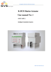
2.1 Model Explanation
Model shown on product nameplate indicates the series name, applicable type of power
supply, power class and the version of software and hardware, etc. via the combination
of numbers, symbols and letters.
GK500 - 4 T 1.5 B- XX - XX
A0~Z9:customized hardware code
Product Series
01~99:customized software code
2:200V
4:400V
Default:no inbuilt brake unit
B:with inbuilt brake unit
T:triphase
1.5:1.5kW
Fig. 2-1 Product model explanation
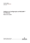
2.2 Nameplate Information
Fig. 2-2 Nameplate information
-7-
Chapter 2 Product Information
GK500 User Manual
2.3 Information of Product Model
Table 2-1 Product model and technical data
Power
rating
(kW)
Output
current
(A)
Triphase input
current
(A)
GK500-2T0.4B
0.4
2.6
3.2
5.5
0.4
GK500-2T0.75B
0.75
4.5
6.3
9.2
0.75
GK500-2T1.5B
1.5
7.5
9
14.5
1.5
GK500-2T2.2B
2.2
9.6
15
23
2.2
GK500-4T0.75B
0.75
2.5
3.5
/
0.75
GK500-4T1.5B
1.5
3.8
6.2
/
1.5
GK500-4T2.2B
2.2
5.5
9.2
/
2.2
GK500-4T3.7B
3.7
9
14.9
/
3.7
Model
Voltage
200V*
400V
Single-phase
input current
(A)
Applicable
motor
(kW)
Brake
unit
inbuilt
* 200V drives are applicable for triphase 200V and single-phase 200v
2.4 Technical Features of GK500
Table 2-2 Technical Features of GK500
Power input
Power output
Rated input
voltage
3-phase
AC208V/AC220V/AC230V/AC240V/AC380V/AC400V/
AC415V/AC440V/AC460V/AC480V
1-phase
AC220V/AC230V/AC240V
Rated input
current
See Section 2.3
Frequency
50Hz/60Hz, tolerance ±5%
Allowable
range of
voltage
Continuous voltage fluctuation ±10%, short fluctuation
-15%~+10%
Voltage out-of-balance rate <3%, distortion rate as per
the requirements IEC61800-2
Applicable
motor (kW)
Rated current
(A)
Output voltage
(V)
Output
frequency (Hz)
See Section 2.3
See Section 2.3
3-phase: 0~ rated input voltage, error < ±3%
0.00~ 600.00Hz; unit: 0.01Hz
-8-
GK500 User Manual
Chapter 2 Product Information
Overload
capacity
V/f patterns
Control
characteristics
Speed
regulation
range
Speed
accuracy
Speed
fluctuation
Torque
response
Start torque
Start frequency
Accel/
Decel time
Carrier
frequency
Basic functions
Frequency
setting
Motor started
methods
Motor stopped
methods
Dynamic
braking
capacity
Basic functions
DC braking
capacity
Input terminals
Output
terminals
150% - 1min; 180% - 10s; 200% - 0.5s
V/f control
Sensor-less vector control 1
1:100 ( V/f , sensor-less vector control 1)
±0.5% (V/f control)
±0.2% (sensor-less vector control 1)
±0.3% (sensor-less vector control 1)
< 10ms (sensor-less vector control 1)
0.5Hz: 180% (V/f control, sensor-less vector control 1)
0.00~ 600.00Hz
0.00~60000s
0.7kHz~12kHz
Digital setting + keypad ∧/∨
Digital setting + terminal UP/DOWN
Potentiometer
Communication
Analog setting (AI1)
Started from starting frequency
DC braking and then started
Ramp to stop
Coast to stop
Ramp stop + DC brake
Brake unit threshold voltage:
400V input: 650V~750V
200V input: 325V~375V
service time: 0.0~100.0s
DC braking start frequency: 0.00~600.00Hz
DC braking current: 0.0~100.0%
DC braking time: 0.0~30.00s
4 digital inputs
1 analog, current/voltage type selectable
1 digital output
1 relay output
1 analog output, voltage/current output selectable; can
-9-
Chapter 2 Product Information
Featured
functions
Protection
functions
output signals such as setting frequency, or output
frequency, etc
various master & auxiliary commands and their switch, a variety of
Accel/Decel curves optional, analog auto correction, 8-step speed
programmable, three faults history, over excitation brake, over voltage
stall protection, under voltage stall protection, restart upon power loss,
skip frequency, frequency binding, four kinds of Accel/Decel time, process
PID, autotuning, field-weakening control
Refer to Chapter 6- Troubleshooting
Place of
operation
Altitude
Environment
Others
GK500 User Manual
Ambient
temperature
Relative
humidity
Vibration
Storage
temperature
Efficiency at
rated Amps
Installation
IP grade
Cooling
method
Indoors, no direct sunlight, free from dust, no corrosive
gases, no flammable gases, no oil mist, no water vapor,
no water drop and salt, etc.
0~2000m
De-rate 1% for every 100m when the altitude is above
1000 meters
-10℃~50℃
0~95%, no condensation
Less than 5.9m/s2 (0.6g)
-40℃~+70℃
At rated Amps ≥93%
Wall-mounted, Din-rail
IP20
Forced air cooling
- 10 -
GK500 User Manual
Chapter 2 Product Information
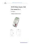
2.5 Parts Drawing
Mounting
holes
DIN-rail
groove
Nameplate
Keypad
Lower
casing
Cover
Middle
casing
Fig. 2-3 Parts drawing
2.6 Configuration, Mounting Dimensions and Weight
Fig. 2-4 External dimensions
- 11 -
Chapter 2 Product Information
GK500 User Manual
Table 2-3 Dimensions and weight
Dimensions(mm)
Model
Weight
W
H
D
W1
H1
Mounting
holes
(dia)
(kg)
75
166
168
59
154
4.5
1.4
85
188
172
69
175
4.5
2.0
GK500-2T0.4B
GK500-2T0.75B
GK500-4T0.75B
GK500-4T1.5B
GK500-2T1.5B
GK500-2T2.2B
GK500-4T2.2B
GK500-4T3.7B
2.7 External Dimensions of Keypad
Keypad model of GK500 series mini AC motor drive is KBU-BX2 whose configuration
and external dimensions are shown in Fig. 2-5. The cabinet hole dimensions are as
shown in Fig. 2-6. when remote keypad mounting is required.
Fig. 2-5 External dimensions of KBU-BX2
- 12 -
GK500 User Manual
Chapter 2 Product Information
Fig. 2-6 Cabinet hole dimensions when remote keypad mounting required
- 13 -
Chapter 3 Installation and Wiring
GK500 User Manual
Chapter 3 Installation and Wiring
3.1 Installation Environment
1) Ambient temperature in the range of -10℃~ 50℃.
2) Drive should be installed on surface of flame retardant object, with adequate
surrounding space for heat dissipation.
3) Installation should be performed where vibration is less than 5.9m/s2 (0.6g).
4) No moisture and direct sunlight.
5) Do not install in areas with grease dirt, dust, metal particles, or salty substances
6) Do not expose to an atmosphere with flammable gases, corrosive gases, explosive
gases or other harmful gases.
3.2 Minimum Mounting Clearances
To ensure favorable heat dissipation, mount the drive upright on a flat, vertical and level
surface as per Fig. 3.1.
GK500 series can be wall-mounted or DIN-rail mounted. When installation is
performed inside cabinet, the product shall be mounted side by side to the greatest
extent while adequate surrounding space shall be preserved for favorable heat
dissipation.
Fixing buckle
Ventilation
clearance
DIN-Rail
Ventilation
clearance
Fig. 3-1 Minimum mounting clearances
- 14 -
GK500 User Manual
Chapter 3 Installation and Wiring
ATTENTION:
If a number of drives are mounted in one cabinet, parallel side-by-side mounting is
recommended.
3.3 Remove & Mount Keypad and Cover
3.3.1
Remove and Mount Keypad
Remove keypad
Press the buckle of keypad as indicated by number "1" in Fig. 3-2 a), then pull the
keypad out to release as indicated by "2".
Mount keypad
Slightly slant the keypad in the direction as indicated by number "1" in Fig. 3-2 b)
and align it to clamping port at lower part of keypad bracket, then press it in as
indicated by "2".
When there is a "click" sound, it indicates clamping has been properly made.
a) Remove keypad
b) Mount keypad
Fig. 3-2 Remove and mount keypad
3.3.2
Open & Close the Cover
Open the cover
Pull out as indicated by “1” in Fig. 3-3 a) with thumb.
Close the cover
After the completion of wiring, press the cover as indicated by “1” in Fig. 3-3 b).
- 15 -
Chapter 3 Installation and Wiring
GK500 User Manual
When there is a “click” sound, it indicates clamping has been well completed.
a)
Open the cover
b) Close the cover
Fig. 3-3 Open and close the cover
3.4 Selection of Peripheral Devices
Table 3-1 Selection of peripheral devices
Model
Breaker(A)
Brake unit
Contactor(A)
Power(W)
Resistor(Ω)
GK500-2T0.4B
16
10
70
≥200
GK500-2T0.75B
25
16
70
≥200
GK500-2T1.5B
32
25
260
≥100
GK500-2T2.2B
40
32
260
≥75
GK500-4T0.75B
16
10
300
≥150
GK500-4T1.5B
GK500-4T2.2B
GK500-4T3.7B
16
16
40
10
10
32
450
600
600
≥100
≥75
≥75
* All models have inbuilt brake unit, and brake resistors should be sourced. Strictly conform to the
requirement in the form. Failure to comply may result in equipment damage.
- 16 -
GK500 User Manual
Chapter 3 Installation and Wiring
3.5 Terminal Configuration
Ground terminal
Main circuit terminal
Control circuit terminal
Ground terminal
Main circuit terminal
Fig. 3-4 Terminal configuration
3.6 Main Circuit Terminals and Wiring
WARNING
Only qualified personnel familiar with AC motor drives are allowed to implement wiring.
Failure to comply may result in equipment damage and/or personnel injury even death.
Wiring should be in strict accordance with this manual, otherwise hazard of electric
shock or equipment damage exists.
Make sure input power supply has been completely disconnected before wiring
operation. Failure to comply will result in personnel injury even death.
All wiring operations and lines should comply with EMC and national and local industrial
safety regulations and/or electrical codes. The conductor diameter should be in
accordance with recommendations of this manual. Otherwise, hazard of equipment
damage, fire, and/or personnel injury exists.
- 17 -
Chapter 3 Installation and Wiring
GK500 User Manual
Since leakage current of the drive may exceed 3.5mA, for safety's sake, the drive and
the motor must be grounded so as to avoid hazard of electric shock.
Be sure to perform wiring in strict accordance with the drive terminal marks. Never
connect three-phase power supply to output terminals U/T1, V/T2 and W/T3. Failure to
comply will result in equipment damage.
Only mount braking resistors at terminals
/B1and B2.
Wiring screws and bolts for main circuit terminals must be screwed tightly. Failure to
comply may result in faults and/or equipment damage.
ATTENTION
Signal wires should to the best of possibility be away from main power lines. In the
event that this cannot be ensured, vertical cross arrangement should be adopted,
reducing EMI interference to the signal wires as much as possible.
In case the motor cable exceeds 100m, an appropriate output reactor should be
mounted.
3.6.1
Main Circuit Terminals
Terminal marks
Specification
Uniphase/Triphase AC power supply input (connect L1/L,
L3/N when the input is uniphase)
L1/L、L2、L3/N
/B1、B2
Brake resistor wiring terminals
/B1、
DC power supply input terminals
U/T1、V/T2、W/T3
Triphase AC output terminals
Ground terminal PE
3.6.2
Terminal Screw and Wiring Requirement
Table 3-2 Terminal screw and wiring requirement
Power terminal
Ground terminal
Cable
(mm2)
Scew
Torque
(kgf.cm)
Cable
(mm2)
Scre
w
Torque
(kgf.cm
)
GK500-2T0.4B
2.5
M3.5
15±0.5
2.5
M3.5
15±0.5
GK500-2T0.75B
2.5
M3.5
15±0.5
2.5
M3.5
15±0.5
Model
- 18 -
GK500 User Manual
Chapter 3 Installation and Wiring
Power terminal
Ground terminal
Cable
(mm2)
Scew
Torque
(kgf.cm)
Cable
(mm2)
Scre
w
Torque
(kgf.cm
)
GK500-2T1.5B
4
M3.5
15±0.5
2.5
M3.5
15±0.5
GK500-2T2.2B
6
M3.5
15±0.5
4
M3.5
15±0.5
GK500-4T0.75B
2.5
M3.5
15±0.5
2.5
M3.5
15±0.5
GK500-4T1.5B
4
M3.5
15±0.5
4
M3.5
15±0.5
GK500-4T2.2B
6
M3.5
15±0.5
4
M3.5
15±0.5
GK500-4T3.7B
6
M3.5
15±0.5
6
M3.5
15±0.5
Model
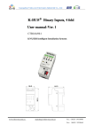
3.7 Control Terminal Wiring
WARNING
Only qualified personnel familiar with AC motor drives are allowed to implement wiring.
Failure to comply may result in equipment damage and/or personnel injury even death.
Wiring should be in strict accordance with this manual, otherwise hazard of electric
shock or equipment damage exists.
Make sure input power supply has been completely disconnected before wiring
operation. Failure to comply will result in personnel injury even death.
All wiring operations and lines should comply with EMC and national and local industrial
safety regulations and/or electrical codes. The conductor diameter should be in
accordance with recommendations of this manual. Otherwise, hazard of equipment
damage, fire, and/or personnel injury exists.
Screws or bolts for terminal wiring must be screwed tightly.
AC 220V signal is prohibited from connecting to other terminals than control terminals
RA, RB and RC.
ATTENTION
Signal wires should to the best of possibility be away from main power lines. If this
cannot be ensured, vertical cross arrangement should be adopted, reducing EMI
interference to the signal wires as much as possible.
- 19 -
Chapter 3 Installation and Wiring
GK500 User Manual
Brake Resistor
Braker
Contactor
AC
Power
Supply
+ /B1
B2
-
L1/L
U/T1
L2
V/T2
L3/N
GK500
M
W/T3
Motor
Grounding
电源地
+24V
Keypad
COM
X1
X2
X3
X4
Digital In 1
Digital In 2
Digital In 3
Digital In 4
RA
RB
RC
Analog In
DC:0~10V/0~20mA
PT
Relay Out 1
250V AC/3A
30V DC/3A
+10V Analog In Reference
Voltage
AI
GND
+24V
Y
Analog Out
DC:0~10V/0~20mA
485
MODBUS
COMM
485+
485GND
AO
GND
Paired
Cable
Shielded
Cable
Fig. 3-5 Wiring diagram
- 20 -
OC Output 1
GK500 User Manual
Chapter 3 Installation and Wiring
3.8 Control Terminal Specification
Table 3-3 Control terminal specification
Category
Termin
al
Terminal
designation
+10V
Analog input
reference voltage
GND
Analog ground
Specification
10.3V ±3%
Analog
input
AI1
Analog input
Maximum output current 25mA
The resistance of external potentiometer
should be larger than 400Ω
Connect with COM interiorly
0~20mA: input impedance - 500Ω, maximum
input current - 25mA
0~10V: input impedance - 100kΩ, maximum
input voltage - 12.5V
Can be jumped between 0~20mA and 0~10V,
factory default: 0~10V
0~20mA: impedance - 200Ω-500Ω
AO
Analog output
GND
Digital
input
0~10V: impedance- 10kΩ
Can be jumped between 0~20 mA and 0~
10V, factory default: 0~10V
Analog
output
Analog ground
+24V
+24V
COM
+24V ground
X1~X4
Digital input
Terminal 1~4
Connect with COM interiorly
24V±10%
Maximal load 100mA
Connect with GND interiorly
Input: 24VDC, 5mA
Freq range: 0~200Hz
Voltage range: 22V~26V
Voltage range: 0~24V
Digital
output
Y
Open collector
output
Relay
output
RA/RB/
RC
Control board relay
output
RA-RB: NC; RA-RC: NO
485 differential
signal +
485 differential
signal 485 communication
shileded grounding
Rate:
4800/9600/19200/38400/57600/115200bps
Maximum distance - 500m (standard network
cable used)
485+
Terminal
485
Interface
485−
GND
Current voltage: 0~50mA
Contact capacity: 250VAC/3A, 30VDC/3A
Connected with COM interiorly
- 21 -
Chapter 3 Installation and Wiring
Category
Keypad
interface
GK500 User Manual
Termin
al
Terminal
designation
GND
485 communication
shield grounding
CN4
Keypad interface
GND
485 communication
shield grounding
Specification
Isolated from COM interiorly
Maximum communication distance is 5m
when connected to Keypad
Use GTAKE dedicated cable
3.9 Control Terminal Usage
3.9.1
Lay-out of Control Terminals
Fig. 3-6 Lay-out of control terminals
3.9.2
Control Terminal Screw and Wiring Requirement
Table 3-6 Terminal screw and wiring specification
Cable type
Cable requirement (mm2)
Screw
Torque (kgf.cm)
Shielded cable
1.0
M3
5±0.5
3.9.3
Instructions of Analog Input/Output Terminals
Being particularly vulnerable to noise, analog input & output signals cables should be as
short as possible, shielded, and their shielded layers should be properly grounded close
to the side of drive. The cables should not exceed 20m.
Control cables shall be kept no less than 20cm away from main circuit and strong
current lines (e.g. power lines, motor lines, relay lines and contactor lines) and should
not be arranged in parallel with strong current lines. In case it is inevitable to intersect
strong current line, vertical wiring is recommended to avoid drive faults as a result of
- 22 -
GK500 User Manual
Chapter 3 Installation and Wiring
noise.
Where analog input & output signals are severely interfered, the side of analog
signal source should be provided with filter capacitor or ferrite core.
3.9.4
Instructions of Digital Input/Output Terminals
Digital input & output signals cables should be as short as possible, shielded, and their
shielded layers should be properly grounded close to the side of drive. The cables
should not exceed 20m. When active drive is selected, take necessary filtering measures
against power crosstalk, for which dry contact control is recommended.
Control cables shall be kept no less than 20cm away from main circuit and strong
current lines (e.g. power lines, motor lines, relay lines and contactor lines) and should
not be arranged in parallel with strong current lines. In case it is inevitable to intersect
strong current line, vertical wiring is recommended to avoid drive faults as a result of
noise. Operating instructions for switching value input terminal.
Instructions of digital input terminal
Dry contact
24V
External
Controller
Drive
+24V
+5V
COM
1
X1
+5V
4
GND
X4
Shielded Cable
Near-end Grounded
GND
Fig. 3-7 Dry contact wiring
- 23 -
Chapter 3 Installation and Wiring
GK500 User Manual
Open collector
24V
External
Controller
Drive
+5V
+24V
COM
1
X1
GND
+5V
X4
4
GND
Shielded Cable
Near-end
Grounded
Fig. 3-8 Open collector wiring
Instructions of digital output terminal
Instructions of Y output terminal
24V
24V
+24V
+5V
+24V
+5V
Y
Y
Pull-up
resistor
≤30V
Pull-up
resistor
COM
COM
Drive
Drive
a) Internal power supply
b) External power supply
Fig. 3-9 Wiring when Y output with pull-up resistor
24V
24V
+24V
+24V
+5V
+5V
Y
Y
Relay
COM
COM
Drive
Drive
a) Internal power supply
b) External power supply
- 24 -
GK500 User Manual
Chapter 3 Installation and Wiring
Fig. 3-10 Wiring when Y output drive relay
ATTENTION:
When relay coil voltage is lower than 24V, a resistor as voltage divider selected
based on coil impedance should be mounted between relay and output terminal,.
Wiring instruction of relay output terminal
RA/RB/RC are relay contacts. RA and RB are normally closed, while RA and RC are
normally open. See parameter C1-02 for details.
ATTENTION:
In case inductive load (e.g. electromagnetic relay or contactor) is to be driven, a
surge voltage absorbing circuit such as RC absorbing circuit, piezoresistor or
fly-wheel diode etc. shall be mounted. Absorbing devices should be mounted close to
the end of relay or contactor.
3.10 Instruction of Signal Switches
Fig. 3-11 Jumper diagram of signal switching
Terminal
Function
Default
AI
I: current input(0~20mA),V: voltage input(0~10V)
0~10V
AO
I: current output(0~20mA),V: voltage output(0~10V)
0~10V
3.11 EMI Solutions
Due to its working principle, the drive will inevitably produce certain noise that may
influence and disturb other equipment. Moreover, since the internal weak electric signal
of drive is also susceptible to the interference of drive itself and other equipment, EMI
problems shall be inevitable. In order to reduce or avoid the interference of drive to
external environment and protect drive against interference from external environment,
this section makes a brief description of noise abatement, ground handling, leakage
current suppression and the application of power line filters.
- 25 -
Chapter 3 Installation and Wiring
3.11.1
GK500 User Manual
Noise Abatement
When peripheral equipment and drive share the power supply of one system, noise
from drive may be transmitted to other equipment in this system via power lines and
result in misoperation and/or faults. In such a case, the following measures could be
taken:
1) Mount input noise filter at input terminal of the drive;
2) Mount power supply filter at power input terminal of affected equipment;
3) Use isolation transformer to isolate the noise transmission path between
other equipment and the drive.
As the wiring of peripheral equipment and drive constitutes a circuit, the unavoidable
earthing leakage current of inverter will cause equipment misoperation and/or faults.
Disconnect the grounding connection of equipment may avoid this misoperation
and/or faults
Sensitive equipment and signal lines shall be mounted as far away from drive as
possible.
Signal lines should be provided with shielded layer and reliably grounded.
Alternatively, signal cable could be put into metallic conduits between which the
distance shall be no less than 20cm, and shall be kept as far away from drive and its
peripheral devices, cables as possible. Never make signal lines in parallel with
power lines or bundle them up.
Signal lines must orthogonally cross power lines if this cross inevitable.
Motor cables shall be placed in thick protective screen like more than 2mm-thick
pipelines or buried cement groove, also, power lines can be put into metallic conduit
and grounded well with shielded cables.
Use 4-core motor cables of which one is grounded at close side of the drive and the
other side is connected to motor enclosure.
Input and output terminals of drive are respectively equipped with radio noise filter
and linear noise filter. For example, ferrite common mode choke can restrain
radiation noise of power lines.
3.11.2
Grounding
Recommended ground electrode is shown in the figure below:
Drive
PE
Other
Devices
PE
Fig. 3-12 Grounding
- 26 -
GK500 User Manual
Chapter 3 Installation and Wiring
Use to the fullest extent the maximum standard size of grounding cables to reduce the
impedance of grounding system;
Grounding wires should be as short as possible;
Grounding point shall be as close to the drive as possible;
One wire of 4-core motor cables shall be grounded at the drive side and connected to
grounding terminal of motor at the other side. Better effect will be achieved if motor
and drive are provided with dedicated ground electrodes;
When grounding terminals of various parts of system are linked together, leakage
current turns into a noise source that may influence other equipment in the system,
thus, grounding terminals of the drive and other vulnerable equipment should be
separated.
Grounding cable shall be kept away from inlet & output of noise-sensitive equipment.
3.11.3
Leakage Current Suppression
Leakage current passes through the line-to-line and ground distributed capacitors at
input & output sides of drive, and its size is associated with the capacitance of distributed
capacitor and the carrier frequency. Leakage current is classified into ground leakage
current and line-to-line leakage current.
Ground leakage current not only circulates inside drive system, but may also influence
other equipment via ground loop. Such a leakage current may result in malfunction of
RCD and other equipment. The higher the carrier frequency of drive is, the bigger the
ground leakage current would be. The longer the motor cables and the bigger the
parasitic capacitance are, the bigger the ground leakage current would be. Therefore,
the most immediate and effective method for suppression of ground leakage current is
to reduce carrier frequency and minimize the length of motor cables.
The higher harmonics of line-to-line leakage current that passes through between
cables at output side of drive will Accel the aging of cables and may bring about
malfunction of other equipment. The higher the carrier frequency of drive is, the bigger
the line-to-line leakage current would be. The longer the motor cables and the bigger
the parasitic capacitance are, the bigger the line-to-line leakage current would be.
Therefore, the most immediate and effective method for suppression of ground
leakage current is to reduce carrier frequency and minimize the length of motor cable.
Line-to-line leakage current can also be effectively suppressed by mounting additional
output reactors.
3.11.4
Use of Power Supply Filter
Since AC drives may generate strong interference and are also sensitive to outside
- 27 -
Chapter 3 Installation and Wiring
GK500 User Manual
interference, power supply filters are recommended. Pay close attention to the following
instructions during the use:
Enclosure of the filter needs to be reliably grounded;
Input lines of the filter shall be kept as far away from output lines as possible so as to
avoid mutual coupling;
Filter shall be as close to the drive side as possible;
Filter and drive must be connected to the same common ground.
- 28 -
GK500 User Manual
Chapter 4 Operation and Run Instructions
Chapter 4 Operation and Run Instructions
4.1 Operation of Keypad
As a human-machine interface, keypad is the main part for the drive to receive command
and display parameters.
Fig. 4-1 Keypad
4.2 Key Functions
On keypad there are 7 keys and 1 knob whose functions are as shown in Table 4-1.
Table 4-1 Key and potentiometer functions on keypad
Symbol
Key name
ENT
Enter key
ESC
Escape key
Up key
Down key
Meaning
1) Parameter code edition enter
2) Confirmation of parameter value settings
1) Return
2) Invalidate parameter editing value
1) Increment of selected digital of parameter code
2) Increment of selected digital of parameter value
3) Increment of set frequency
1) Decrement of selected digital of parameter code
2) Decrement of selected digital of parameter value
3) Decrement of set frequency
- 29 -
Chapter 4 Operation and Run Instructions
Symbol
Key name
GK500 User Manual
Meaning
>>
Shift key
1) Selection of parameter code serial digital
2) Selection of parameter value edited digital
3) Selection of stop/run-status displayed parameters
4) Fault status switched to parameter displayed status
RUN
Run key
Run
STOP
Stop/reset key
RESET
Potentiometer
1) Stop
2) Fault reset
1) Frequency command source
2) Process PID setting
4.3 Keypad Indicators
Keypad is furnished with 6 indicators with functions as stated below.
Table 4-2 Description of indicators
Indicator
Designation
Hz
Frequency indicator
A
V
Current indicator
Voltage indicator
Hz+A
Run speed indicator
A+V
All OFF
Percentage indicator
No unit
RUN
Run status indicator
FWD
REV
Forward indicator
Reverse indicator
Meaning
ON: currently displayed parameter is run frequency
or the unit of current parameter is frequency
Flash: currently displayed parameter is set
frequency
ON: currently displayed parameter is current
ON: currently displayed parameter is voltage
ON: currently displayed parameter is run speed
Flash: currently displayed parameter is set speed
ON: currently displayed parameter is percentage
No unit
ON: Run
OFF: Stopped
Flash: Stopping
ON: If the drive in stop status, forward command
enabled. If the drive in run status, the drive is
running forward
Flash: Forward is switching to reverse
ON: If the drive in stop status, reverse command
enabled. If the drive in run status, the drive is
running reversely.
Flash: Reverse is switching to forward
- 30 -
GK500 User Manual
Chapter 4 Operation and Run Instructions
4.4 Potentiometer Setting
Potentiometer could be frequency setting source or process PID setting programmed by
related parameters. When b0-01 is set to 3, potentiometer is source of master frequency
command. When b0-03 is set to 4, potentiometer is source of auxiliary frequency
command. When unit’s place, decade, or hundreds’ place of b1-01 is set to 4,
potentiometer would be working as frequency setting source of corresponding run
command source.
4.5 Prompt Message Status
Prompt message status shall be displayed at the completion of some certain operations.
For instance, "dEFt2" would be displayed upon the completion of “restore to factory
default (motor parameters inclusive)
Table 4-3 Prompt messages
Characters
LoC-1
Meaning
Characters
Keypad locked 1 (full locked)
Meaning
P-SEt
Password has been set
P-CLr
Password cleared
TUNE
Autotuning
CLr-F
Clear fault record
Keypad protection
dEFt1
Restore to factory default
(motor parameters
exclusive)
Unlock keypad
dEFt2
Restore to factory default
(motor parameter inclusive)
Keypad locked 2
LoC-2
LoC-3
(all locked except RUN,
STOP/RESET)
Keypad locked 3
(all locked except STOP/RESET)
LoC-4
Keypad locked 4
(all locked except shift key)
PrtCt
UnLoC
LoU
Drive undervoltage
Table 4-3 shows meanings of the characters displayed on Keypad.
- 31 -
Chapter 4 Operation and Run Instructions
GK500 User Manual
4.6 Parameter Setting
4.6.1
Parameter System
GK500 series drive parameter group: A0, b0~b2, C0~C4, d0~d2, E0~E1, F0~F1, H0,
L0~L1, U0~U1. Each parameter group contains a number of parameters. Parameter
codes are identified by the combination "parameter group character + parameter
subgroup number + parameter number". For instance, "F1-07" indicates the seventh
parameter code at subgroup 1, group F.
4.6.2
Parameter Displayed Structure
Parameters and the parameter values are subject to a two-tier structure. Parameters
correspond to first-tier display, while parameter values correspond to second-tier display.
The first-tier display is as shown in Fig. 4-2, while the second-tier as Fig. 4-3:
Fig. 4-2 First-tier parameter display
Fig. 4-3 Second-tier parameter display ("3" is the value of b0-00)
- 32 -
GK500 User Manual
Chapter 5 List of Parameters
Chapter 5 List of Parameters
GK500 parameter groups are listed below:
Category
Group A: system parameter
Group b: setting of running
parameters
Group C: input and output
terminals
Group d: motor and control
parameters
Group E: enhanced
function and protection
parameters
Group F: application
Group H: communication
parameters
Group L: keypad keys and
display
Group U: monitoring
Parameter group
A0: system parameters
b0: frequency command
b1: start/stop control
b2: Accel/Decel parameters
C0: digital input
C1: digital output
C2: analog input
C3: analog output
C4: automatic correction of
analog input
d0: motor parameter
d1: motor V/f control parameters
d2: motor vector control
parameters
E0: enhanced function
P64;
P66;
P68;
P69;
P70;
P73;
P75;
P76;
P77;
Related pages
P104
P109
P122
P128
P134
P147
P154
P159
P163
P78; P165
P79; P169
P80; P176
P84; P183
E1: protection parameters
P86; P187
F0: process PID
F1: multi-step frequency
H0: MODBUS communication
parameters
L0: keypad keys
L1: LED display setting
U0: status monitoring
U1: fault history
P87; P191
P89; P197
P95; P213
P95;
P96;
P98;
P100;
P215
P216
P225
P222
Notice:
“﹡” means there is remark related to this parameter
Range: settable and displayable range of parameters
Factory default: The value when restored to factory default. Neither measured
parameter value nor recorded value will be restored.
Attribution:
"△ " means the value of this parameter can be modified in stop and run status;
"×" means the value of this parameter can not be modified at running;
"◎" means this parameter is a measured value that cannot be modified;
- 33 -
Chapter 5 List of Parameters
Param
GK500 User Manual
Designation
Range
Factory
default
Attr
Group A: System Parameter
Group A0: System Parameter
0~FFFF
0000
0: All parameter programming
allowed
Parameter protection
0
1: Only A0-00 and this parameter
programming allowed
0: No operation
1: Clear fault history
2: Restore all parameters to factory
default (motor parameters
Parameter initialization
0
exclusive)
3: Restore all parameters to factory
default (motor parameters
inclusive)
0: V/f control
Motor control technique
0
1: Sensor-less vector control
Group b Setting of Run Parameters
Group b0 Frequency Command
0: Master frequency command
1: Master & auxiliary computation
result
2: Switch between master and
auxiliary command
Frequency command pattern
3: Switch between master frequency
0
command, and master & auxiliary
computation result
4: Switch between auxiliary
frequency command, and master &
auxiliary computation result
0: Digital setting (b0-02) + ∧/∨
adjustment on keypad
1: Digital setting (b0-02) + terminal
UP/DOWN adjustment
Master frequency command source 2: Analog input AI
0
3: Potentiometer
6: Process PID output
8: Multi-step speed
9: Communication
Digital setting of master frequency Lower limit frequency ~ upper limit
50.00Hz
A0-00 Setting of user password
△
A0-02
×
A0-03
A0-09
b0-00
b0-01
b0-02
- 34 -
×
×
×
×
△
GK500 User Manual
Param
b0-03
b0-04
b0-05
b0-06
b0-07
b0-08
b0-09
b0-10
b0-11
b0-12
b0-13
b0-14
b0-15
b0-16
b0-17
Chapter 5 List of Parameters
Designation
Range
Factory
default
frequency
0: No command
1: Digital setting (b0-04) + ∧/∨
adjustment on keypad
2: Digital setting (b0-04) + terminal
UP/DOWN adjustment
3: Analog input AI1
Auxiliary frequency command
4: Analog input AI2
0
source
5: Analog input EAI (on IO expansion
board)
6: X6/DI pulse input
7: Process PID output
8: PLC
9: Multi-step speed
10: Communication
Lower limit frequency ~ upper limit
Digital setting of auxiliary frequency
0.00Hz
frequency
0: Relative to maximum frequency
Range of auxiliary frequency
0
1: Relative to master frequency
Coeff of auxiliary frequency
0.0%~100.0%
100.0%
0: Master + auxiliary
Computation of master and
1: Master - auxiliary
0
auxiliary frequency
2: Max {master, auxiliary}
3: Min {master, auxiliary}
Maximum frequency
Upper limit frequency ~600.00Hz
50.00Hz
Lower limit frequency ~ maximum
Upper limit frequency
50.00Hz
frequency
Lower limit frequency
0.00Hz~upper limit frequency
0.00Hz
Operation when command
0: Run at lower limit frequency
frequency lower than lower limit
1: Run at 0 Hz
0
frequency
2: Stop
Time-delay of stop when command
frequency lower than lower limit
0.0s ~ 6553.5s
0.0s
frequency
Lower limit of skip frequency band 1 0.00Hz~upper limit frequency
0.00Hz
Upper limit of skip frequency band 1 0.00Hz~upper limit frequency
0.00Hz
Lower limit of skip frequency band 2 0.00Hz~upper limit frequency
0.00Hz
Upper limit of skip frequency band 2 0.00Hz~upper limit frequency
0.00Hz
Lower limit of skip frequency band 3 0.00Hz~upper limit frequency
0.00Hz
- 35 -
Attr
×
△
×
×
×
×
×
×
×
×
×
×
×
×
×
Chapter 5 List of Parameters
Param
GK500 User Manual
Designation
Range
b0-18 Upper limit of skip frequency band 3 0.00Hz~upper limit frequency
b0-19 Jog frequency
0.00Hz~upper limit frequency
Group b1 Start/Stop Control
0: Keypad control
b1-00 Run command
1: Terminal control
2: Communication control
Unit's place: frequency command
source bundled under keypad
control:
0: No binding
1: Digital setting (b0-02) + ∧/∨
adjustment on keypad
2: Digital setting (b0-02) + terminal
UP/DOWN adjustment
3: AI
Binding of run command and
4: Keypad potentiometer
b1-01
frequency command
7: Process PID output
9: Multi-step frequency
A: Communication input
Decade: frequency command source
bundled under terminal control (same
as unit's place)
Hundreds place: frequency
command source bundled under
communication control (same as
unit's place)
0: Forward
b1-02 Run direction
1: Reverse
0: Reverse enabled
b1-03 Reverse disabled
1: Reverse disabled
b1-04 Dead time of forward and reverse 0.0s~3600.0s
0: From start frequency
b1-05 Start method
1: DC injection brake then start
b1-06 Start frequency
0.00Hz~upper limit frequency
b1-07 Holding time of start frequency
0.0s~3600.0s
b1-08 DC brake current at start
0.0%~100.0%
b1-09 DC brake time at start
0.00s~30.00s
0: Ramp to stop
b1-13 Stop method
1: Coast to stop
2: Ramp to stop + DC brake
- 36 -
Factory
default
0.00Hz
5.00Hz
Attr
×
△
0
×
000
×
0
△
0
×
0.0s
△
0
×
0.00Hz
0.0s
0.0%
0.00s
×
△
△
△
0
×
GK500 User Manual
Param
Chapter 5 List of Parameters
Designation
Range
b1-14 Start frequency of DC brake stop
b1-15 Brake current
b1-16 Brake time
b1-17
b1-18
b1-19
b1-20
b1-21
b2-00
0.00Hz~upper limit frequency
0.0%~100.0%
0.00s~30.00s
0: Disabled
Overexcitation brake
1: Enabled
0: Disabled
Dynamic brake
1: Enabled
200V: 325V~375V, default: 375V
Dynamic brake threshold voltage
400V: 650V~750V, default: 720V
Auto restart when power up again 0: Disabled
after power loss
1: Enabled
Waiting time of auto restart when
0.0s~10.0s
power up again
Group b2 Accel/Decel Parameters
Accel/Decel time resolution
b2-01
b2-02
b2-03
b2-04
b2-05
b2-06
b2-07
b2-08
Accel time 1
Decel time 1
Accel time 2
Decel time 2
Accel time 3
Decel time 3
Accel time 4
Decel time 4
Decel time when emergency stop
b2-09
enabled
b2-10 Jog Accel time
b2-11 Jog Decel time
b2-12 Accel/Decele curve selection
Accel time switching frequency of
broken-line Accel/Decel
Decel time switching frequency of
b2-14
broken-line Accel/Decel
b2-15 Time of first segment of Accel
b2-13
Factory
default
0.00Hz
0.0%
0.00s
Attr
×
△
△
1
×
0
×
Model
defined
×
0
×
0.0s
△
1
×
0s~600.00s/6000.0s/60000s
0s~600.00s/6000.0s/60000s
0s~600.00s/6000.0s/60000s
0s~600.00s/6000.0s/60000s
0s~600.00s/6000.0s/60000s
0s~600.00s/6000.0s/60000s
0s~600.00s/6000.0s/60000s
0s~600.00s/6000.0s/60000s
0s~600.00s/6000.0s/60000s
6.0s
6.0s
6.0s
6.0s
6.0s
6.0s
6.0s
6.0s
△
△
△
△
△
△
△
△
6.0s
△
0s~600.00s/6000.0s/60000s
0s~600.00s/6000.0s/60000s
0: Linear Accel/Decel
1: Broken-line Accel/Decel
2: S-curve Accel/Decel
6.0s
6.0s
△
△
0
×
0.00Hz~upper limit frequency
0.00Hz
△
0.00Hz~upper limit frequency
0.00Hz
△
0.20s
△
0:0.01s
1:0.1s
2:1s
0.00s~60.00s
- 37 -
Chapter 5 List of Parameters
Param
b2-16
b2-17
b2-18
C0-00
C0-01
C0-02
C0-03
C0-04
C0-08
GK500 User Manual
Designation
Range
S-curve
Time of last segment of Accel
0.00s~60.00s
S-curve
Time of first segment of Decel
0.00s~60.00s
S-curve
Time of last segment of Decel
0.00s~60.00s
S-curve
Group C Input and Output Terminals
Group C0 Digital Input
0: Trigger edge detected + ON
Enabled condition of run command
detected
terminals when power up
1: ON detected
0: No function
Function of terminal X1
1: JOG forward
2: JOG reverse
Function of terminal X2
3: Run forward (FWD)
4: Run reverse (REV)
Function of terminal X3
5: Three-wire control
6: Run suspended
7: External stop
Function of terminal X4
8: Emergency stop
9: Stop command + DC brake
10: DC brake stop
11: Coast to stop
12: Terminal UP
13: Terminal DOWN
14: Clear UP/DOWN (including
keypad ∧/∨) adjustment
15: Multi-step frequency terminal 1
16: Multi-step frequency terminal 2
Function of terminal AI (Digital
17: Multi-step frequency terminal 3
enabled)
19: Accel/Decel time determinant 1
20: Accel/Decel time determinant 2
21: Accel/Decel disabled(ramp stop
not inclusive)
22: External fault input
23: Fault reset (RESET)
27: Run command switched to
keypad control
28: Run command switched to
- 38 -
Factory
default
Attr
0.20s
△
0.20s
△
0.20s
△
0
×
0
×
0
×
0
×
0
×
0
×
GK500 User Manual
Param
Chapter 5 List of Parameters
Designation
Range
Factory
default
Attr
0.010s
△
0.0s
0.0s
△
△
0000
×
0000
×
0000
△
terminal control
29: Run command switched to
communication control
30: Frequency command pattern shift
31: Master frequency command
switched to digital setting b0-02
32: Auxiliary frequency command
switched to digital setting b0-04
33: PID adjustment direction
34: PID paused
35: PID integration paused
36: PID parameter switch
68: Run prohibited
69: DC brake in running
Filtering time of digital input
terminal
C0-12 Delay time of terminal X1
C0-13 Delay time of terminal X2
C0-11
0.000s~1.000s
0.0s~3600.0s
0.0s~3600.0s
Unit's place: X1
0: Positive logic
1: Negative logic
Digital input terminal enabled status Decade: X2 (same as unit's place)
C0-14
setting 1
Hundreds place: X3 (same as unit's
place)
Thousands place: X4 (same as unit's
place)
Unit's place: AI
Digital input terminal enabled status
C0-16
0: Positive logic
setting 2
1: Negative logic
Unit's place: action when stop
0: Clear
1: Holding
Decade: action on power loss
Terminal UP/DOWN frequency
0: Clear
C0-17
adjustment treatment
1: Holding
Hundreds place: integral function
0: No integral function
1: Integral function enabled
Thousands place: run direction
- 39 -
Chapter 5 List of Parameters
Param
GK500 User Manual
Designation
Range
Factory
default
Attr
0.03 Hz/s
△
0
×
000
×
0
△
14
△
0: run direction can not be changed
1: run direction can be changed
C0-18
C0-19
C0-20
C1-00
C1-02
Terminal UP/DOWN frequency
adjustment step size
0.00Hz/s~100.00Hz/s
0: Two-wire mode 1
1: Two-wire mode 2
FWD/REV terminal control mode
2: Three-wire mode 1
3: Three-wire mode 2
000~10F
0: Actual terminal in effect
1: Virtual terminal in effect
Option of virtual input terminal
Unit's place: BIT0~BIT3: X1~X4
Decade: Reserved
Hundreds place: AI
Group C1 Digital Output
Y output function
0: No output
1: Drive undervoltage
2: Drive running preparation
completed
3: Drive is running
4: Drive in 0Hz running (no output at
stop)
5: Drive in 0Hz running (output at
stop)
6: Run direction
7: Frequency attained
8: Upper limit frequency attained
Control board relay output function 9: Lower limit frequency attained
10: Frequency higher than FDT 1
11: Frequency higher than FDT 2
12: Reserved
13: Torque limited
14: Fault output
15: Alarm output
16: Drive (motor) overloaded
prealarm
17: Drive overtemperature prealarm
18: Zero current detection
19: X1
- 40 -
GK500 User Manual
Param
Designation
C1-04 Y output time delay
C1-06 Relay output time delay
C1-08 Enabled state of digital output
C1-09
C1-10
C1-11
C1-12
C1-13
Chapter 5 List of Parameters
Detective object of frequency
doubling technology(FDT)
FDT1 upper bound
FDT1 lower bound
FDT2 upper bound
FDT2 lower bound
Detection width of frequency
C1-14
attained
C1-15 Zero current detection level
C1-16 Zero current detection time
Range
20:X2
25: Consecutive running time
attained
26: Accumulative running time
attained
0.0s~3600.0s
0.0s~3600.0s
Unit's place: Y
0: Positive logic
1: Negative logic
Decade: Reserved
Hundreds place: control board relay
output (same as unit's place)
Factory
default
Attr
0.0s
0.0s
△
△
000
×
Unit's place: FDT1 detective object
0: Set value of speed (frequency
after Accel/Decel)
1: Detected speed value
Decade: FDT2 detective object
0: Set value of speed (frequency
after Accel/Decel)
1: Detected speed value
0.00Hz~maximum frequency
0.00Hz~maximum frequency
0.00Hz~maximum frequency
0.00Hz~maximum frequency
00
△
50.00Hz
49.00Hz
25.00Hz
24.00Hz
△
△
△
△
0.00Hz~maximum frequency
2.50Hz
△
5.0%
0.50s
△
△
000
×
100.0%
×
100.0%
×
0.0%~50.0%
0.01s~50.00s
Group C2 Analog Input
Unit's place: AI input curve
0: Curve 1 (2 points)
C2-00 Analog input curve selection
1: Curve 2 (4 points)
Decade: Potentiometer input curve
(same as unit's place)
C2-01 Maximum input of curve 1
Minimum input of curve 1 ~ 110.0%
Corresponding set value of curve 1
C2-02
-100.0%~100.0%
maximum input
- 41 -
Chapter 5 List of Parameters
Param
GK500 User Manual
Designation
Range
C2-03 Minimum input of curve 1
-110.0% ~ maximum input of curve 1
Corresponding set value of curve 1
C2-04
-100.0%~100.0%
minimum input
C2-05 Curve 2 maximum input
Factory
default
0.0%
Attr
×
0.0%
×
Range: Inflection point A input of
curve 2~110.0%
100.0%
×
Range: -100.0%~100.0%
100.0%
×
Curve 2 inflection point B input ~
curve 2 maximum input
0.0%
×
Range: -100.0%~100.0%
0.0%
×
Range: Curve 2 minimum input ~
curve 2 inflection point A input
0.0%
×
0.0%
×
0.0%
×
0.0%
×
0.01s
0.01s
△
△
0
△
Corresponding set value of curve 2
C2-06
maximum input
C2-07 Curve 2 inflection point A input
Corresponding set value of curve 2
C2-08
inflection point A input
C2-09 Curve 2 inflection point B input
C2-10
Corresponding set value of curve 2
Range: -100.0%~100.0%
inflection point B input
C2-11 Curve 2 minimum input
Range: -110.0%~ curve 2 inflection
point B input
Corresponding set value of curve 2
Range: -100.0%~100.0%
minimum input
C2-21 AI input filtering time
0.000s~10.000s
C2-22 Potentiometer input filtering time
0.000s~10.000s
Group C3 Analog Output
0: No output
1: Command frequency
2: Output frequency
3: Output current
4: Output torque
5: Output voltage
6: Output power
C3-00 AO output function
7: Bus voltage
9: Torque current
10: Magnetic flux current
11:AI
16:Communication input percentage
17: Output frequency before
compensation
18: Output current (related motor
C2-12
- 42 -
GK500 User Manual
Chapter 5 List of Parameters
Factory
default
Attr
0.0%
1.000
0.0s
×
×
△
0
×
Range: 0.00V~10.00V
1.00V
◎
C4-02 Input value of AI calibration point 1 Range: 0.00V~10.00V
1.00V
×
Sampling value of AI calibration
C4-03
point 2
Range: 0.00V~10.00V
9.00V
◎
C4-04 Input value of AI calibration point 2 Range: 0.00V~10.00V
9.00V
×
Sampling value of potentiometer
C4-05
calibration point 1
Range: 0.00V~10.00V
1.00V
◎
Param
Designation
Range
rated current)
-100.0%~100.0%
-2.000~2.000
0.0s~10.0s
Group C4 Automatic Correction of Analog Input
0: No correction
C4-00 Analog corrected channel
1:Correct AI
2:Correct potentiometer
C3-03 AO offset
C3-04 AO gain
C3-05 AO1 filtering time
C4-01
Sampling value of AI calibration
point 1
C4-06
Input value of potentiometer
calibration point 1
Range: 0.00V~10.00V
1.00V
×
C4-07
Sampling value of potentiometer
calibration point 2
Range: 0.00V~10.00V
9.00V
◎
9.00V
×
0
×
Input value of potentiometer
Range: 0.00V~10.00V
calibration point 2
Group d Motor and Control Parameters
Group d0 Motor parameters
0: Ordinary motor
d0-00 Motor type
1: Variable frequency motor
C4-08
d0-01 Motor power rating
d0-02 Motor rated voltage
0.4kW~6553.5kW
200V: 0V~260V
default: 220V
400V: 0V~480V
default: 380V
Model
defined
Model
defined
Model
defined
×
×
d0-03 Motor rated current
0.0A~6553.5A
d0-04 Motor rated frequency
0.00Hz~maximum frequency
50.00Hz
×
d0-05 Motor pole number
1~80
×
d0-06 Motor rated speed
0~65535r/min
4
Model
defined
- 43 -
×
×
Chapter 5 List of Parameters
Param
GK500 User Manual
Designation
Range
Factory
default
Model
defined
Model
defined
Model
defined
Model
defined
Model
defined
Model
defined
Model
defined
Model
defined
Attr
d0-07 Motor stator resistance R1
0.001Ω~65.535Ω
d0-08 Motor leakage inductance L1
0.1mH~6553.5mH
d0-09 Motor rotor resistance R2
0.001Ω~65.535Ω
d0-10 Motor mutual inductance L2
0.1mH~6553.5mH
d0-11 Motor no-load current
0.0A~6553.5A
d0-12 Motor flux weakening coeff 1
0.0000~1.0000
d0-13 Motor flux weakening coeff 2
0.0000~1.0000
d0-14 Motor flux weakening coeff 3
0.0000~1.0000
d0-22 Motor parameter autotune
0: No autotune
1: Static autotune
2: Rotating autotune
0
×
d0-23 Motor overload protection mode
0: No protection
1: Judged from motor current
1
×
5.0min
×
d0-24
Motor overload protection detection
0.1min~15.0min
time
Group d1 Motor V/f Control Parameters
×
×
×
×
×
×
×
×
d1-00 V/f curve setting
0: Linear V/f
1: Multi-stage V/f (d1-01~d1-08)
0
×
d1-01
d1-02
d1-03
d1-04
d1-05
d1-06
d1-07
d1-08
d1-09
0.00Hz~motor rated frequency
0.0%~100.0%
d1-05~d1-01
0.0%~100.0%
d1-07~d1-03
0.0%~100.0%
0.00Hz~d1-05
0.0%~100.0%
0.0%~30.0%
50.00Hz
100.0%
0.00Hz
0.0%
0.00Hz
0.0%
0.00Hz
0.0%
0.0%
×
×
×
×
×
×
×
×
△
0.0%~400.0%
100.0%
△
V/f frequency value f3
V/f voltage value V3
V/f frequency value f2
V/f voltage value V2
V/f frequency value f1
V/f voltage value V1
V/f frequency value f0
V/f voltage value V0
Torque boost
d1-10 Slip compensation gain
- 44 -
GK500 User Manual
Param
Designation
d1-12 Current limited source
d1-13
d1-14
d1-15
d1-16
d1-17
d2-01
d2-02
d2-03
Chapter 5 List of Parameters
Range
0: Disabled
1: Set by d1-13
2: Set by AI
Digital setting of current limited
20.0%~200.0%
value
Current limited coeff at flux
0.001~1.000
weakening
Energy saving percentage
0%~40.0%
V/f oscillation suppression gain 1 0~3000
V/f oscillation suppression gain 2 0~3000
Group d2 Motor Vector Control Parameters
ASR high-speed proportional gain
0.0~20.0
Kp1
ASR high-speed integration time
0.000s~8.000s
Ti1
ASR low-speed proportional gain
Kp2
0.0~20.0
d2-04 ASR low-speed integration time Ti2 0.000s~8.000s
d2-05
d2-06
d2-07
d2-08
d2-09
d2-10
d2-11
d2-12
d2-13
d2-14
d2-15
d2-16
d2-17
ASR switch frequency 1
ASR switch frequency 2
ASR input filtering time
ASR output filtering time
ACR proportion coeff Kp
ACR integration coeff Ki
Pre-excitation time
0.00Hz~d2-06
d2-05~upper limit frequency
0.0ms~500.0ms
0.0ms~500.0ms
0.000~4.000
0.000~4.000
0.000s~5.000s
0: d2-14 digital setting
Electric-driven torque limited source 1: AI
5: Communication
0: d2-15 digital setting
Brake torque limited source
1: AI
5: Communication
Digital setting of electric-driven
0.0%~200.0%
torque
Digital setting of brake torque
0.0%~200.0%
Torque limited coeff in flux
0.0%~100.0%
weakening
Electric-driven slip compensation
10.0%~300.0%
gain
- 45 -
Factory
default
Attr
1
×
160.0%
×
0.500
△
0.0%
16
20
△
△
△
2.0
△
0.500
△
2.0
△
0.500
△
5.00Hz
10.00Hz
0.3ms
0.3ms
1.000
1.000
0.200s
△
△
△
△
△
△
△
0
×
0
×
180.0%
△
180.0%
△
50.0%
△
100.0%
△
Chapter 5 List of Parameters
Param
GK500 User Manual
Designation
Range
d2-18 Brake slip compensation gain
10.0%~300.0%
Group E Enhanced Function and Protection Parameters
Group E0 Enhanced Function
E0-00 Carrier frequency
0.7kHz~12.0kHz
Unit's place: carrier frequency
adjusted with temperature
0: Auto-adjusted
1: Not adjusted
Decade: PWM modulation mode
0: Five-segment and seven-segment
E0-01 PWM optimization
auto-shift
1: Five-segment mode
2: Seven-segment mode
Hundreds place: over-modulation
adjustment
0: Disabled
1: Enabled
Unit's place: selection when
consecutive running time attained:
0: Continue to run
1: Stop and fault alarm
Decade: selection when
E0-02 Selection when run time attained accumulative run time attained:
0: Continue to run
1: Stop and fault alarm
Hundreds place: unit of run time
0: Second
1: Hour
E0-03 Consecutive run time setting
0.0s(h)~6000.0s(h)
E0-04 Accumulative running time setting 0.0s(h)~6000.0s(h)
Group E1 Protection Parameters
0: Prohibited
E1-00 Overvoltage stall
1: Allowed
200V: 100%~120% default: 116%
E1-01 Overvoltage stall protection voltage
400V: 120%~150% default: 135%
0: Disabled
E1-02 Undervoltage stall
1: Enabled
Unit's place: detection option:
E1-03 Overload prealarm
0: Always detect
1: Detect at constant speed only
- 46 -
Factory
default
100.0%
Attr
△
8.0kHz
△
020
×
000
×
0.0
0.0
×
×
1
×
Model
Defined
×
0
×
000
×
GK500 User Manual
Param
Chapter 5 List of Parameters
Designation
E1-04 Overload prealarm threshold
E1-05 Overload prealarm detected time
E1-06 Protected action 1
E1-07 Protected action 2
E1-08 Fault memorized at power loss
E1-09 Times of automatic reset
E1-10 Interval of automatic reset
E1-11 Relay action on drive fault
Range
Decade: compared object:
0: Motor rated current
1: Drive rated current
Hundreds place: alarm option
0: Continue to run
1: Protection enabled and coast to
stop
20.0%~200.0%
0.1s~60.0s
Unit's place: reserved
Decade: temperature sampling
disconnection action:
0: Protection enabled and coast stop
1: Continue to run
Hundreds place: reserved
Thousands place: abnormal terminal
communication:
0: Protection enabled and coast stop
1: Continue to run
Unit's place: reserved
Decad: current detection circuit failed
0: Protection enabled and coast stop
1: Continue to run
Hundreds place: reserved
Thousands place: output phase loss:
0: Protection enabled and coast stop
1: Continue to run
0: Not memorized at power loss
1: Memorized at power loss
0~20
2.0s~20.0s
Unit's place: when undervoltage fault
occurs
0: No action
1: Action enabled
Decade: when fault locked
0: No action
1: Action enabled
Hundreds place: interval of automatic
- 47 -
Factory
default
Attr
180.0%
5.0s
△
△
0000
×
0000
×
0
×
0
2.0s
×
×
010
×
Chapter 5 List of Parameters
Param
GK500 User Manual
Designation
Range
Factory
default
Attr
80.0℃
△
0
×
50.0%
△
0
×
11
×
0
×
0.00s
0.00s
0.00s
2.0
1.0s
0.0s
2.0
1.0s
0.0s
△
△
△
△
△
△
△
△
△
0
×
reset
0: No action
1: Action enabled
E1-13
Drive overtemperature prealarm
threshold
0.0℃~100.0℃
Group F Application
Group F0 Process PID
0: F0-01 digital setting
1: AI
F0-00 PID setting
2: Potentiometer
5: Communication
F0-01 PID digital setting
0.0%~100.0%
0: AI
F0-02 PID feedback
8: Communication
Unit's place: output frequency
0: Must be the same direction as
setting run direction
1: Opposite direction allowed
F0-03 PID adjustment
Decade: integration selection
0: Integral continued when frequency
attains upper/lower frequency
1: Integral stopped when frequency
attains upper/lower limit
PID positive and negative
0: Positive adjustment
F0-04
adjustment
1: Negative adjustment
F0-05 Filtering time of PID setting
0.00s~60.00s
F0-06 Filtering time of PID feedback
0.00s~60.00s
F0-07 Filtering time of PID output
0.00s~60.00s
F0-08 Proportional gain Kp1
0.0~100.0
F0-09 Integration time Ti1
0.001s~50.000s
F0-10 Differential time Td1
0.0s~100.0s
F0-11 Proportional gain Kp2
0.0~100.0
F0-12 Integration time Ti2
0.001s~50.000s
F0-13 Differential time Td2
0.0s~100.0s
F0-14 PID parameter switch selection
0: No switch, determined by
parameters Kp1, Ti1 and Td1
1: Auto switch on the basis of input
offset
2: Switched by terminal
- 48 -
GK500 User Manual
Chapter 5 List of Parameters
0.0%~100.0%
0.006s~50.000s
0.0%~100.0%
0.0%~100.0%
0.0%~100.0%
0.0s~3600.0s
0.0%~100.0%
0.0s~30.0s
Factory
default
20.0%
0.008s
0.0%
0.5%
0.0%
0.0s
0.0%
1.0s
0.00Hz~mximum frequency
50.00Hz
△
F0-24 PID computation option
0
△
F1-00
0
×
0
×
0.00Hz
△
0.00 Hz
△
0.00 Hz
△
0.00 Hz
△
0.00 Hz
△
Param
Designation
F0-15
F0-16
F0-17
F0-18
F0-19
F0-20
F0-21
F0-22
PID auto-switch Input offset
Sampling period T
PID offset limit
PID differential limit
PID initial value
Holding time of PID initial value
PID feedback loss detection value
PID feedback loss detection time
Maximum frequency when opposite
F0-23
to command run direction
F1-01
F1-02
F1-03
F1-04
F1-05
F1-06
Range
0: No computation in stop status
1: Computation continued in stop
status
Group F1 Multi-step Frequency
0: Digital setting F1-02
1: Digital setting b0-02 + keypad ∧/∨
adjustment
Frequency command source of
2: Digital setting b0-02 + terminal
multi-step 0
UP/DOWN adjustment
3: AI
7: Process PID output
8: Communication
0: Digital setting F1-03
1: Digital setting b0-04 + keypad ∧/∨
adjustment
Frequency command source of
2: Digital setting b0-04 + terminal
multi-step 1
UP/DOWN
3: AI
7: Process PID output
8: Communication
Lower limit frequency ~ upper limit
Multi-step frequency 0
frequency
Lower limit frequency ~ upper limit
Multi-step frequency 1
frequency
Lower limit frequency ~ upper limit
Multi-step frequency 2
frequency
Lower limit frequency ~ upper limit
Multi-step frequency 3
frequency
Multi-step frequency 4
Lower limit frequency ~ upper limit
- 49 -
Attr
△
△
△
△
×
△
△
△
Chapter 5 List of Parameters
Param
F1-07
F1-08
F1-09
H0-01
H0-02
H0-03
H0-04
H0-05
H0-06
H0-07
GK500 User Manual
Designation
Range
frequency
Lower limit frequency ~ upper limit
Multi-step frequency 5
frequency
Lower limit frequency ~ upper limit
Multi-step frequency 6
frequency
Lower limit frequency ~ upper limit
Multi-step frequency 7
frequency
Group H Communication Parameters
Group H0 MODBUS Communication Parameters
Unit's place: baud rate
0: 4800bps
1: 9600bps
2: 19200bps
3: 38400bps
4: 57600bps
Decade: data format
0: 1-8-2-N format, RTU
1: 1-8-1-E format, RTU
RS-485 port communication
2: 1-8-1-O Format, RTU
configuration
3: 1-7-2-N format, ASCII
4: 1-7-1-E format, ASCII
5: 1-7-1-O format, ASCII
Hundreds place: connection type
0: Direct cable connection (232/485)
1: MODEM (232)
Thousands place: storage
0: Not stored at power loss
1: Stored at power loss
RS-485 communication address
0~247, 0 is broadcast address
Time out detection
0.0s~1000.0s
Communication time delay
0ms~1000ms
0: Independently used
Master/Slave option
1: As master
2: As slave
0:b0-02
Parameter storage address
1:F0-01
Proportional factor of received
0.0%~1000.0%
frequency
Group L Keys and Display of Keypad
Group L0 Keys of Keypad
- 50 -
Factory
default
Attr
0.00 Hz
△
0.00 Hz
△
0.00 Hz
△
0002
×
1
0.0s
0ms
×
×
×
0
×
0
×
100.0%
△
GK500 User Manual
Param
Chapter 5 List of Parameters
Designation
L0-01 Keys locked selection
L0-02 Function of STOP key
L0-03 ∧/∨ frequency adjustment
Range
0: Not locked
1: Full locked
2: Keys locked other than RUN,
STOP/RESET
3: Keys locked other than
STOP/RESET
4: Keys locked other than >>
0: STOP key valid only when under
keypad control
1: STOP key valid under any run
command source
Unit's place: selection on stop
0: Clear on stop
1: Holding on stop
Decade: selection on power loss
0: Clear on power loss
1: Holding on power loss
Hundreds place: integral selection
0: Integral disabled
1: Integral enabled
Thousands place: run direction
0: Run direction not allowed to
change
1: Run direction allowed to change
Step size of ∧/∨frequency
0.00Hz/s~10.00Hz/s
adjustment
Group L1 LED Display Setting
Setting of binary system:
0: Display disabled
1: Display enabled
Unit's place:
BIT0: Running frequency (Hz)
LED displayed parameter settings
L1-00
BIT1: Command frequency (Hz)
on running status
BIT2: Bus voltage (V)
BIT3: Output current (A)
Decade:
BIT0: Output torque (%)
BIT1: Output power (kW)
L0-04
- 51 -
Factory
default
Attr
0
△
0
△
0100
△
0.03 Hz/s
△
000F
△
Chapter 5 List of Parameters
Param
GK500 User Manual
Designation
Range
BIT2: Output voltage (V)
BIT3: Motor speed (r/min)
Hundreds place:
BIT0: AI (V)
BIT1: Potentiometer (V)
BIT2: Reserved
BIT3: Reserved
Note: when this parameter is set to
0000, running frequency (Hz) would
be displayed as default
Setting of binary system:
0: Display disabled
1: Display enabled
Unit's place:
BIT0: Command frequency (Hz)
BIT1: Bus voltage (V)
BIT2: Input terminal status
BIT3: Output terminal status
Decade:
BIT0: AI (V)
BIT1: Potentiometer (V)
LED displayed parameter settings
L1-02
BIT2: Reserved
on stop status
BIT3: Reserved
Hundreds place:
BIT0: PID setting (%)
BIT1: PID feedback (%)
BIT2: Reserved
BIT3: Reserved
Thousands place: Reserved
U0-00
U0-01
U0-02
U0-03
U0-04
Run frequency
Set frequency
Bus voltage
Output voltage
Output current
Note: when this parameter is set to
0000, the set frequency would be
displayed as default (Hz)
Group U Monitoring
Group U0 Status Monitoring
0.00Hz~600.00Hz
0.00Hz~600.00Hz
0V~65535V
0V~65535V
0.0A~6553.5A
- 52 -
Factory
default
Attr
0003
△
0.00Hz
0.00Hz
0V
0V
0.0A
◎
◎
◎
◎
◎
GK500 User Manual
Param
U0-05
U0-06
U0-09
U0-10
Designation
Output torque
Output power
Master frequency setting
Auxiliary frequency setting
U0-11 Drive status
U0-12
U0-13
U0-15
U0-18
U0-19
U0-20
U0-21
U0-22
U0-30
U0-31
U0-33
U0-36
U0-37
Chapter 5 List of Parameters
AI input voltage
Potentiometer input voltage
AO output
Status of digital input terminal
Status of digital output terminal
PID set
PID feedback
PID input offset
Cumulative power-up time
Cumulative run time
IGBT temperature
Run command record at LoU
Fault code record at LoU
U0-39 Current detection fault source
Range
0.0%~300.0%
0.0%~300.0%
0.00Hz~600.00Hz
0.00Hz~600.00Hz
Unit's place: run status
0: Accelerating
1: Decelerating
2: Constant speed running
Decade: drive status
0: Stop
1: Run status
2: Autotuning
0.00V~10.00V
0.00V~10.00V
0.0%~100.0%
0~F
0~5
0.0%~100.0%
0.0%~100.0%
-100.0%~100.0%
0h~65535h
0h~65535h
-40.0℃~100.0℃
0~1
0~100
0: No fault source
1: IU
2: IV
3: IW
Higher of keypad ∧/∨ stored
0,value
Lower of keypad ∧/∨ stored
U0-43
-999.9Hz~600.0Hz
value
Higher of terminal UP/DOWN stored
U0-44
0,value
Lower of terminal UP/DOWN
U0-45
-999.9Hz~600.0Hz
stored value
Group U1 Fault History
U0-42
- 53 -
Factory
default
0.0%
0.0%
0.00Hz
0.00Hz
Attr
◎
◎
◎
◎
00
◎
0.00V
0.00V
0.0%
0
0
0.0%
0.0%
0.0%
0h
0h
0.0℃
0
0
◎
◎
◎
◎
◎
◎
◎
◎
◎
◎
◎
◎
◎
0
◎
0
◎
0.00Hz
◎
0
◎
0.00Hz
◎
Chapter 5 List of Parameters
Param
Designation
U1-00 Fault 1 code(latest)
U1-01
U1-02
U1-03
U1-05
U1-06
U1-07
U1-08
U1-09
GK500 User Manual
Fault 1 run frequency
Fault 1 output current
Fault 1 bus voltage
Fault 1 IGBT temperature
Fault 1 input terminal status
Fault 1 output terminal status
Fault 1cumulative run time
Fault 2 code
Range
0: No fault
1: Accel overcurrent
2: Constant-speed overcurrent
3: Decel overcurrent
4: Accel overvoltage
5: Constant-speed overvoltage
6: Decel overvoltage
7: Module protection
8: Autotuning failed
9: Drive overloaded
10: Motor overloaded
11: Current detection abnormal
12: Ground short-circuit protection at
output side
14: Phase loss at output side
16: Heat sink overtemperature
protection
18: Module temperature detection
disconnection
24: External equipment malfunction
26: Consecutive run time attained
27: Accumulative run time attained
28: Power supply abnormal in
running
31: Port communication abnormal
36: CPU interference fault
37: Reference protection
38: 5V power supply out-of-limit
40: AI input out-of-limit
41: Undervoltage protection
45: PID feedback loss
46: Interior communication abnormal
0.00Hz~600.00Hz
0.0A~6553.5A
0V~10000V
-40.0℃~100.0℃
0~FFFF
0~FFFF
0h~65535h
Same as U1-00
- 54 -
Factory
default
Attr
0
◎
0.00Hz
0.0A
0V
0.0℃
0000
0000
0h
0
◎
◎
◎
◎
◎
◎
◎
◎
GK500 User Manual
Param
U1-10
U1-11
U1-12
U1-14
U1-15
U1-16
U1-17
U1-18
U1-19
U1-20
U1-21
U1-23
U1-24
U1-25
U1-26
Chapter 5 List of Parameters
Designation
Fault 2 run frequency
Fault 2 output current
Fault 2 bus voltage
Fault 2 IGBT temperature
Fault 2 input terminal status
Fault 2 output terminal status
Fault 2 cumulative run time
Fault 3 code
Fault 3 run frequency
Fault 3 output current
Fault 3 bus voltage
Fault 3 IGBT temperature
Fault 3 input terminal status
Fault 3 output terminal status
Fault 3 cumulative run time
Range
0.00Hz~600.00Hz
0.0A~6553.5A
0V~10000V
-40.0℃~100.0℃
0~FFFF
0~FFFF
0h~65535h
Same as U1-00
0.00Hz~600.00Hz
0.0A~6553.5A
0V~1000V
-40.0℃~100.0℃
0~FFFF
0~FFFF
0h~65535h
- 55 -
Factory
default
0.00Hz
0.0A
0V
0.0℃
0000
0000
0h
0
0.00Hz
0.0A
0V
0.0℃
0000
0000
0h
Attr
◎
◎
◎
◎
◎
◎
◎
◎
◎
◎
◎
◎
◎
◎
◎
Chapter 5 List of Parameters
GK500 User Manual
Remark:
C0-19
FWD/REV terminal control
mode
Factory default:
0
Range: 0~3
There are four different types when run command is determined by FED/REV terminal.
This terminal control mode takes no effect on JOG.
0: Two-wire mode 1
FWD terminal inputs forward run command, while REV terminal inputs reverse run
command.
Table 5-1
+24V
FWD
REV
K1
OFF
OFF
Run
command
Stop
command
K2
OFF
ON
Reverse
ON
OFF
Forward
ON
ON
Stop
PLC
Drive
变
频
FWD
器
REV
COM
Fig. 5-1
1: Two-wire mode 2
FWD terminal inputs run command, while REV terminal inputs run direction.
Table 5-2
+24V
PLC
变
Drive
频
FWD
器
REV
K1
K2
COM
FWD
REV
OFF
OFF
Running
command
Stop
OFF
ON
Reverse
ON
OFF
Forward
ON
ON
Stop
Fig. 5-2
2: Three-wire mode 1
FWD terminal controls forward run of the drive, REV terminal controls reverse run, and
digital input terminal "three-wire run" controls the stop. Input signals of all these three
terminals take effect when trigger edge is detected.
- 56 -
GK500 User Manual
Chapter 5 List of Parameters
+24V
PLC
Three-wire
三线式运
run
行端子Xi
terminal
变 Xi
FWD
频
器
Drive
REV
SB1
SB2
SB3
COM
Fig. 5-3 Three-wire mode 1
SB1 is a stop button, by pressing which the drive will stop;
SB2 is a FORWARD button, by pressing which forward running will be activated;
SB3 is a REVERSE button, by pressing which reverse running will be activated.
Xi is a digital input terminal. In this case, it is necessary to define the function of
corresponding terminal as "three-wire run" terminal.
3: Three-wire mode 2
FWD terminal controls the running, while running direction is determined by REV
terminal. Digital input terminal "three-wire running" controls the stop.
+24V
PLC
Three-wire
三线式运
running
行端子Xi
terminal
Xi
变
FWD
频
器
Drive
REV
SB1
SB2
K
COM
Fig. 5-4 Three-wire mode 2
SB1 is a stop button, by pressing which the drive will stop;
SB2 is a RUN button, by pressing which the drive will run. When switch K is open,
run is forward, while when it is closed, run is reverse.
Xi is a digital input terminal. In this case, it is necessary to define the function of
corresponding terminal as "three-wire run" terminal.
- 57 -
Chapter 5 List of Parameters
GK500 User Manual
C1-10
FDT1 upper bound
Range: 0.00Hz~maximum freq
Factory default:
50.00Hz
C1-11
FDT1 lower bound
Range: 0.00Hz~ maximum freq
Factory default:
49.00Hz
These parameters should be set with digital output terminals "FDT1" (FDT2 features the
same)
Take FDT1 for example, the drive outputs ON signal when output frequency exceeds
upper bound of FDT1 and will not output OFF signal unless output frequency drops to
below lower bound of FDT1. Please set C1-10 to be larger to some certain extent than
C1-11, avoiding status change frequently. See Fig. 5-5:
输出频率
Output frequency
FDT1FDT1电平上限
upper limit
FDT1FDT1电平下限
lower limit
Time
时间
FDT1 terminal
FDT1端子
Time
时间
Fig. 5-5
C2-00
Analog input curve selection
Range: 00~11
Factory default: 000
Curves of analog input AI are selected by this parameter.
Unit's place: AI input curve selection
0: Curve 1 (2 points)
Defined by C2-01~C2-04. See Fig. 5-6, Fig 5-7, Fig 5-8, and Fig 5-9.
1: Curve 2 (4 points)
Defined by C2-05~C2-12. See Fig 5-10 and Fig 5-11.
Decade: Potentiometer input curve selection: same as AI
Curve 1 is defined by C2-01~C2-04.
- 58 -
GK500 User Manual
Chapter 5 List of Parameters
Input value of C2-01, C2-03:
AI: voltage input 0~10V and current input 0~20mA can be jumped.
When it is 0~10V: 0V corresponds to 0%, 10V corresponds to 100%.
When it is 0~20mA: 0mA corresponds to 0%, 20mA corresponds to 100%.
Potentiometer only supports 0~10V voltage input. Corresponding set values of C2-02,
C2-04:
When corresponding set value is frequency: 100% is maximal frequency, -100% is
negative maximal frequency;
When corresponding set value is current: 100% means 2 times drive rated current,
less than or equal to 0% means 0A;
When corresponding set value is torque: 100% means 2 times rated torque, -100%
means -2 times rated torque;
When corresponding set value is output voltage: 100% corresponds to motor rated
voltage, less than or equal to 0% corresponds to 0V.
Corresponding
对应设定值set value
Set value that
曲线1最大输入
corresponds
to
对应设定值
maximum (C2-02)
input of
Minimum
curve 1 (C2-02)
input of
curve 1
曲线1最小输入
(C2-03)
Corresponding set value
对应设定值
Set value that
corresponds
to
曲线1最大输入
maximum
input of
对应设定值
curve 1 (C2-02)
(C2-02)
(C2-03)
Set value that
corresponds
to
曲线1最小输入
minimum对应设定值
input of
curve 1 (C2-04)
(C2-04)
Set value that
corresponds
to
曲线1最小输入
minimum 对应设定值
input of
(C2-04)
curve 1 (C2-04)
曲线1最小输入
Minimum
(C2-03)
input
of curve
1 (C2-03)
曲线1最大输入
Maximum
(C2-01)
input
of curve
1 (C2-01)
AI模拟量
AI
analog
曲线1最大输入
Maximum
(C2-01)
input
of curve
1 (C2-01)
AI模拟量
AI
analog
Fig. 5-6
Fig. 5-7
Corresponding
set value
对应设定值
Corresponding
对应设定值set value
Set value that
曲线1最小输入
corresponds
to
minimum对应设定值
input of
(C2-04)
curve 1 (C2-04)
Set value that
曲线1最大输入
corresponds
to
对应设定值
maximum
input of
(C2-02)
curve 1 (C2-02)
曲线1最小输入
Minimum
(C2-03)
input
of curve
1 (C2-03)
Set value that
曲线1最小输入
corresponds
to
对应设定值
minimum input
of
(C2-04)
curve 1 (C2-04)
曲线1最小输入
Minimum
Set value that input
(C2-03)
of curve
corresponds to 1 (C2-03)
曲线1最大输入
AI模拟量 maximum
AI
input
曲线1最大输入
对应设定值
Maximum
analog of curve
1
(C2-01)
(C2-02)
input
of curve
(C2-02)
1 (C2-01)
- 59 -
Maximum
input
of curve
曲线1最大输入
1 (C2-01)
(C2-01)
AIAI模拟量
analog
Chapter 5 List of Parameters
GK500 User Manual
Fig. 5-8
Fig. 5-9
Specification of curve 2 input value is as below.
Voltage input:
1) AI: 0% corresponds to 0V or 0mA, 100% corresponds to 10V or 20mA.
2) Potentiometer: 0% corresponds to 0V, 100% corresponds 10V.
Curve 2 is defined by C2-05~C2-12. Curve 2 input and its corresponding set value is the
same as curve 1. However, the difference is Curve 1 is a straight line, while Curve 2 is a
broken line with 2 inflection points.
Corresponding
对应设定值set value
Corresponding
set value
对应设定值
Set value
that corresponds
曲线2最大输入对应
to maximum
input of curve 2
设定值(C2-06)
(C2-06)
Set valueB点输入对应
corresponds to
point B input
(C2-10)
设定值(C2-10)
Set value that corresponds
曲线2最大输入对应
to maximum
input of curve 2
(C2-06)设定值(C2-06)
Set value
corresponds to
B点输入对应
point B设定值(C2-10)
input (C2-10)
Set valueA点输入对应
corresponds to
point A input
(C2-08)
设定值(C2-08)
A点输入对应
Set value
corresponds to
point A设定值(C2-08)
input (C2-08)
曲线2最小输入对应
Set value
that corresponds
to minimum
input of curve 2
设定值(C2-12)
(C2-12)
AI
analog
AI模拟量
曲线2最大输入
Maximum
input of
curve
2 (C2-05)
(C2-05)
A点输入
曲线2最小输入
Minimum
input of
Point
A input
curve 2 (C2-11)
(C2-11)
(C2-07)
(C2-07)
曲线2最大输入
Maximum
input of
curve
2 (C2-05)
(C2-05)
AI analog
AI模拟量
Set value曲线2最小输入对应
that corresponds
to minimum
input of curve 2
设定值(C2-12)
(C2-12)
曲线2最小输入
A点输入
B点输入
Minimum input Point
B input
A Point
of curve 2
(C2-09)
(C2-11)
(C2-07)
(C2-09)
input
(C2-11)
(C2-07)
B点输入
Point
B input
(C2-09)
(C2-09)
Fig. 5-10
Fig. 5-11
C3-03
AO offset
Range: -100.0%~100.0%
Factory default: 0.0%
C3-04
AO gain
Range: -2.000~2.000
Factory default: 1.000
When users need to chang AO measuring range or correct the error of meter, it can be
realized by setting of C3-03 and C3-04. When using factory default set: 0~10V (or
0~20mA) of AO corresponds to “0~maximun”. By expressing standard output of AO as x,
the adjusted AO output as y, the gain as k, and the offset as b (100% of offset
corresponds to 10V or 20mA), there is the equation: y=kx+b
Example:
Set C3-00 to 2: output frequency. Standard AO output: AO outputs 0V when output
frequency is 0, and outputs 10V when output frequency is maximum frequency. If AO1 is
requested to output 2V when output frequency is 0Hz, and to output 8V when output
frequency is the maximum frequency.
There is: 2=k×0+b; 8=k×10+b. Through these two equations, we obtain: k = 0.6, b =
2V, i.e. C3-03 is set to 20.0% while C3-04 is set to 0.600.
- 60 -
GK500 User Manual
Chapter 5 List of Parameters
Additional examples are shown as below:
AO1调整后输出
AO1
output after adjustment
10V
(C3-04) = 200%
(C3-04) = 100%
5V
0
10V
AO
standard output
AO1标准输出
Fig. 5-12 Diagram of influence of AO gain on output
AO output
after adjustment
AO1调整后输出
10V
(C3-03) = 15%
(C3-03) = 0%
1.5V
0
8.5V 10V
AO1标准输出
AO
standard output
Fig. 5-13 Diagram of influence of AO offset on output
C4-00
Analog corrected channel
Range: 0~2
Factory default: 0
Take potentiometer as example, autocorrection process is as below:
1) Set C4-00 to 2 in stop status and press ENT key to confirm. In this way,
potentiometer is selected as correction channel.
2) Input a relatively low analog voltage (e.g. about 1V) via potentiometer, and input
the theoretical value of this analog voltage by C4-06 after the stabilization of this
voltage input, and then press ENT key to confirm.
3) Input a relatively high analog voltage (e.g. about 5V) via potentiometer, and input
the theoretical value of this analog voltage by C4-08 after the stabilization of this
voltage input, and then press ENT key to confirm.
4) Upon the successful correction, parameter value of C4-00 will be restored to
zero.
ATTENTION:
Set the theoretical value or actual value of analog voltage in C4-06 and C4-08.
- 61 -
Chapter 5 List of Parameters
GK500 User Manual
This value can be either the set value of analog output of peripheral equipment,
or the actual voltage value of analog input measured by a multimeter or other
instruments.
C4-05 and C4-07 are the sampling values of analog input voltage. These values
is for reference only. Do not write the value of C4-05 directly into C4-06, or write
the value of C4-07 directly into C4-08.
- 62 -
GK600 User Manual
Chapter 7 Maintenance
Chapter 6 Troubleshooting
6.1 Fault Causes and Troubleshooting
Once drive fault occurs, please identify the causes of fault carefully and make a detailed
record of fault symptom. To seek services, please contact the dealer.
Parameters U1-00, U1-09 and U1-18 are used to view the fault history of fault 1
(fault 1 = the most recent fault), fault 2 (fault 2 = the second most recent fault), and fault 3
(fault 3 = the third most recent fault). Faults are recorded with numeric codes (0~46),
while the fault information that corresponds to each numeric fault code is specified in the
table below.
Table of Fault Codes
Fault
code
1
2
Fault
Display
oC1
oC2
Fault description
Accel
overcurrent
Constant-speed
overcurrent
Causes
Solutions
Torque boost is too big
under V/f control
Reduce torque boost
value
Starting frequency is too
high
Drop starting frequency
Accel time is too short
Prolong the Accel time
Motor parameters are
improperly set
Set the parameters
correctly according to
motor nameplate
Output short circuit
(phase-to-phase short
circuit or output ground
short circuit)
Check motor connection
and output ground
impedance
Overload is too heavy
Reduce the load
Inappropriate V/f curve
under V/f control
Set V/f curve correctly
Restart the rotating
motor
Reduce current limited
value or start through
speed search
Output short circuit
(phase-to-phase short
circuit or output ground
short circuit)
Check motor connection
and output ground
impedance
- 63 -
Chapter 7 Maintenance
Fault
code
3
4
5
6
Fault
Display
oC3
ov1
ov2
ov3
GK500 User Manual
Fault description
Decel
overcurrent
Accel
overvoltage
Constant-speed
overvoltage
Decel
overvoltage
Causes
Solutions
Overload is too heavy
Reduce the load
Power rating of the drive
is relatively small
Select appropriate drive
power rating
Input voltage is too low
Check power grid
voltage
Output short circuit
(phase-to-phase short
circuit or output ground
short circuit)
Check motor connection
and output ground
impedance
Load inertia is too big
Use dynamic brake
Decel time is too short
Prolong the Decel time
Input voltage is too low
Check power grid
voltage
Load inertia is too big
Use dynamic brake
Abnormal input voltage
Check power grid
voltage
Output short circuit
(phase-to-phase short
circuit or output ground
short circuit)
Check motor connection
and output ground
impedance
Load variation is too big
Check the load
Abnormal input voltage
Check power grid
voltage
Output short circuit
(phase-to-phase short
circuit or output ground
short circuit)
Check motor connection
and output ground
impedance
Improper parameter
setting of regulator under
SVC control
Properly set regulator
parameters
Load inertia is too big
Use dynamic braking
Abnormal input voltage
Check power grid
voltage
Output short circuit
(phase-to-phase short
Check motor connection
and output ground
- 64 -
GK600 User Manual
Fault
code
Fault
Display
Chapter 7 Maintenance
Fault description
Causes
circuit or output ground
short circuit)
7
8
9
FAL
tUN
oL1
Module
protection
Parameter
identification
failed
Drive
overloaded
Solutions
impedance
Improper parameter
setting of regulator under
SVC control
Properly set regulator
parameters
Decel time is too short
Prolong the Decel time
Output short circuit
(phase-to-phase short
circuit or output ground
short circuit)
Check motor connection
and output ground
impedance
Fan damaged or air duct
blocked
Clear the air duct or
replace the fan
Direct connection of
inverter module
Seek services
Switching power supply
damaged
Seek services
Control board abnormal
Seek services
Ambient temperature is
too high
Reduce ambient
temperature
Loose connection of
control board
Pull out and reinsert the
cables of control board
Overvoltage or
overcurrent
Handle it with the
solutions of overvoltage
or overcurrent
Bad motor connection
Check motor connection
Identification during
rotation of the motor
Identification in
stationary status of the
motor
Bias between motor
parameters and their
setting is too big
Set the parameters
correctly according to
motor nameplate
Torque boost is too big
under V/f control
Reduce torque boost
value
Starting frequency is too
high
Drop starting frequency
- 65 -
Chapter 7 Maintenance
Fault
code
10
11
Fault
Display
oL2
CtC
GK500 User Manual
Fault description
Motor
overloaded
Current
detection
abnormal
Causes
Solutions
Accel/Decel time is too
short
Prolong the Accel/Decel
time
Motor parameters are
improperly set
Set the parameters
correctly according to
motor nameplate
Output short circuit
(phase-to-phase short
circuit and output ground
short circuit)
Check motor connection
and output ground
impedance
Load is too heavy
Reduce the load
Inappropriate V/f curve
under V/f control
Set V/f curve correctly
Restart the rotating
motor
Reduce current limited
value or start through
speed search
Torque boost is too big
under V/f control
Reduce torque boost
value
Inappropriate V/f curve
under V/f control
Set V/f curve correctly
Motor parameters are
improperly set
Set the parameters
correctly according to
motor nameplate
Improper setting of motor
overloaded protection
time
Properly set the motor
overloaded protection
time
Motor stalled or sharp
variation of load
Identify the causes of
motor stalling or check
the load condition
Long-term running of
ordinary motor at low
speed with heavy load
Select variable
frequency motor
Abnormal connection of
control board
Seek services
Switching power supply
damaged
Seek services
Hall device damaged
Seek services
- 66 -
GK600 User Manual
Fault
code
14
16
18
Fault
Display
oPL
oH1
oH3
Chapter 7 Maintenance
Fault description
Output phase
loss
Heat sink
thermal
protection
Module
temperature
detection
undisconnected
Causes
Solutions
Output ground leakage
current is too big
Seek services
Motor cable connection
abnormal
Check motor connection
Imbalance among motor
three phases
Check or replace the
motor
Incorrect setting of vector
control parameters
Correctly set vector
control parameters
Ambient temperature is
too high
Drop ambient
temperature
Fan damaged
Replace the fan
Air duct blocked
Clear air duct
Temperature sensor
abnormal
Seek services
Inverter module
abnormal
Seek services
Module detection circuit
damaged
Seek services
Thermistor damaged
Seek services
Ambient temperature is
too low
Raise ambient
temperature
External fault terminal is
enabled
Check the status of
external fault terminal
Stall condition lasts too
long
Check if the load is
abnormal
24
PEr
External
equipment error
26
to2
Consecutive
running time
attained
"Consecutive running
time attained" enabled
See specification of
Group E0
27
to3
Cumulative
running time
attained
"Cumulative running time
attained" enabled
See specification of
Group E0
28
SUE
Power supply
abnormal at
running
Fluctuation of grid
voltage is out of range
Check input power grid
voltage
- 67 -
Chapter 7 Maintenance
Fault
code
31
36
37
38
40
41
45
46
Fault
Display
TrC
CPU
oCr
SP1
Fault description
Port
communication
abnormal
CPU
interference
fault
Benchmark
protection
5V power supply
out-of-limit
AIP
AI input
out-of-limit
LoU
Undervoltage
protection
Plo
ICF
GK500 User Manual
PID detection
out-of-limit
Interior COMM.
alarm
Causes
Solutions
Improper setting of baud
rate
Set properly
Communication port
disconnection
Reconnect
Upper computer/device
does not work
Make upper
computer/device work
Drive communication
parameter error
Set properly
Severe EMI
Check peripheral
equipment or seek
services
Control board abnormal
Seek services
Switching power supply
damaged
Seek services
Control board damaged
Seek services
Switching power supply
damaged
Seek services
Control board damaged
Seek services
Control board damaged
Seek services
AI input is too high or low
Set AI input within
correct range
Input voltage abnormal
Check input power grid
voltage
Switching power supply
abnormal
Seek services
PID feedback
abnormal
channel
Check the
channel
Inappropriate setting of
PID parameters
Set properly
Drive communication
chip abnormal
Ask for help from GTAKE
Bad EMI
- 68 -
feedback
Check
surrounding
equipment or ask for
help
GK600 User Manual
Chapter 7 Maintenance
Chapter 7 Maintenance
Ambient temperature, humidity, salt mist, dust, vibration, aging and wear of internal
components may result in drive faults. Routine maintenance shall be performed during
the use and storage.
ATTENTION:
Please make sure the power supply of the drive has been cut off, and DC bus voltage
has discharged to 0V before the maintenance.
7.1 Routine Inspection
Please use the drive in the environment recommended by this manual, and perform
routine inspection in accordance with the table below.
Inspection
items
Operating
environment
Drive
Inspection aspects
Inspection
methods
Criteria
Temperature
Thermometer
-10℃~50℃
Humidity
Hygrometer
5%~95%, condensation not
allowed
Dust, oil stains,
moisture and
water-drop
Visual
inspection
No filthy mud, oil stains and water
drop
Vibration
Observation
Smooth running. No abnormal
vibration
Gas
Smell, visual
inspection
No peculiar smell and abnormal
smoke
Noise
Listen
No abnormal noise
Gas
Smell, visual
inspection
No peculiar smell and abnormal
smoke
Appearance
Visual
inspection
No defect and deformation
Heat dissipation and
temperature rise
Visual
inspection
No dust and/or fiber particles in
air duct, normal working of fans,
normal air speed and volume, no
abnormal temperature rise
- 69 -
Chapter 7 Maintenance
Inspection
items
Motor
Running
status
parameters
GK500 User Manual
Inspection aspects
Inspection
methods
Criteria
Thermal status
Smell
No abnormal heating and
scorching smell
Noise
Listen
No abnormal noise
Vibration
Observe,
listen
No abnormal vibration and sound
Power supply input
current
Ammeter
In the range of requirement
Power supply input
voltage
Voltmeter
In the range of requirement
Drive output current
Ammeter
In the range of requirement
Drive output voltage
Voltmeter
In the range of requirement
Thermometer
The difference between U0-33
displayed temperature and
ambient temperature does not
exceed 40℃
Temperature
7.2 Regular Maintenance
Users should perform regular inspection of the drive every 3~6 months, so as to
eliminate the potential faults.
ATTENTION:
Please make sure power supply of the drive has been cut off, and DC bus
voltage has been discharged to 0V prior to maintenance.
Never leave screws, gaskets, conductors, tools and other metal articles inside
the drive. Failure to comply may result in equipment damage.
Never modify the interior components of the drive in any condition. Failure to
comply may result in equipment damage.
Inspection items
Measures
Check if control terminal screws are loose
Tighten
Check if main circuit terminal screws are loose
Tighten
Check if ground terminal screws are loose
Tighten
Check if drive mounting screws are loose
Tighten
- 70 -
GK600 User Manual
Chapter 7 Maintenance
Inspection items
Measures
Check if there are damage on power cables and
control cables
Replace the damaged cables
Check if there is dust on circuit board
Clear it up
Check if air duct is blocked
Clear it up
Check if drive insulation is damaged
Test the ground terminal with
500V megameter after all input
and
output
terminals
are
short-circuited via conductors.
Ground test on individual
terminals is strictly prohibited
since this may cause damage to
inverter.
Check if motor insulation is damaged
Remove input terminals U/V/W of
motor from drive and test the
motor
alone
with
500V
megameter. Failure to comply
may result in drive damage.
Check if the storage period of the drive is over two
years
Carry out power-on test, during
which, the voltage should be
boosted to rated value gradually
using a voltage regulator; be
sure to run at no load for more
than 5 hours.
7.3 Replacement of Vulnerable Parts
Vulnerable parts of drive include cooling fan, electrolytic capacitor, relay or contactor etc.
The service lives of these parts are subject to environment and working conditions. To
maintain a favorable operating environment is conducive to improving the service life of
parts and components; routine inspection and maintenance also contributes to effective
improvement of parts' service life. To prolong the service life of entire drive, the cooling
fan, electrolytic capacitor, relay or contactor and other vulnerable parts should be
subjected to routine inspection according to the table below. Please replace the
abnormal parts (if any) in time.
- 71 -
Chapter 7 Maintenance
Vulnerable
parts
Fan
GK500 User Manual
Service life
30,000~40,000h
Cause of damage
Wear of bearing and
aging of blade
Criteria
Check if fan blades have
cracks
Check if there is abnormal
vibration and noise on working
7.4 Storage
Storage environment should meet the requirements as set forth in the table below.
Items
Storage
-40~+70℃
temperature
Storage
humidity
Recommended storage method and
environment
Requirements
5~95%
A space with low vibration and
low content of salt where there
Storage
is no direct exposure to
environment sunlight, dust, no corrosive or
flammable gas, oil stain, vapor
and water drop
In case of long-term storage, areas with an
ambient temperature of less than 30℃ are
recommended
Avoid the storage in areas where
temperature shock may result in
condensation and freezing
Product could be sealed with plastic film and
dessicant
Product could be sealed with plastic film and
dessicant
ATTENTION:
Since long-term storage may lead to the deterioration of electrolytic capacitor, the
inverter must be powered on once in case storage period exceeds 2 years. During
the power-on, input voltage must be boosted to rated value gradually using a
voltage regulator, and be sure to have the inverter operate at no load for more than
5 hours.
- 72 -
GK600 User Manual
Chapter 7 Maintenance
- 73 -