1
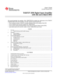
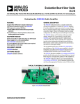
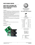
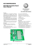
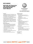
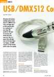
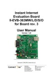
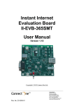
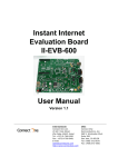
NCV7430GEVK
Advance Information
USB-LIN Interface V3
Evaluation Board
User'sManual
http://onsemi.com
Introduction
USB−LIN Interface provides a simple USB interface that connects
PC and LIN based slave device. The USB part is self−powered and
optically isolated from the LIN transceiver that can be supplied either
via dedicated DC input connector or directly via LIN connector. This
device is compatible e.g. with NCV7430 Evaluation software which
incorporates all the necessary drivers.
The design incorporates the lowest bill of materials, minimized
board size and allows easy interconnection in case of multiple nodes
network.
EVAL BOARD USER’S MANUAL
Features
•
•
•
•
•
•
•
LIN Interface
LIN Compliant to 2.0 and 2.1 and J2602 Specification
USB Driven LIN Master Node
Bus−powered USB
Optically Isolated LIN Bus
Precise LIN Frames Timing
Wide Supply Voltage Range
ESD Protected
Version 3
12V DC
USB
USB
Power
LIN
Activity
LIN
Power
LIN
Figure 1. Hardware
Table 1. ABSOLUTE MAXIMUM RATINGS
(ON Semiconductor LIN Interface works in combination with the custom NCV7430 Evaluation GUI interface. No additional power supply is needed other than the supplied 12 V AC/DC adapter which powers the LIN Interface through DC Power Input connector.)
Symbol
Parameter
Min
Max
Units
VBUS
USB Supply Voltage
−0.3
5.5
V
VBAT
External Supply Voltage
−0.3
42
V
IBAT
Maximum supply current
−
2
A
VLIN
Maximum voltage at LIN bus pin
−45
45
V
Ambient temperature
−40
85
°C
TA
Stresses exceeding Maximum Ratings may damage the device. Maximum Ratings are stress ratings only. Functional operation above the
Recommended Operating Conditions is not implied. Extended exposure to stresses above the Recommended Operating Conditions may affect
device reliability.
Table 2. RECOMMENDED OPERATING RATINGS
Symbol
Parameter
Min
Max
Units
VBUS
USB Supply Voltage
4.75
5.25
V
VBAT
External Supply Voltage
5.5
18
V
VLIN
Maximum voltage at LIN bus pin
5.5
18
V
Ambient temperature
−40
85
°C
TA
This document contains information on a new product. Specifications and information
herein are subject to change without notice.
© Semiconductor Components Industries, LLC, 2013
August, 2013 − Rev. P0
1
Publication Order Number:
EVBUM2212/D
NCV7430GEVK
Table 3. PIN FUNCTION DESCRIPTION
Connector
Pin
Pin Name
Description
LIN INTERFACE
VBAT External Power Supply Input (LIN Bus side)
Power
LIN (RJ11)
USB
1
VBAT
2
LIN
3
GND
4
NC
VBAT Supply Voltage Output / Input (LIN Interface can be supplied through this pin)
LIN Bus Line
Ground Connection
Not Connected
USB Connector
NC
GND
LIN
VBAT
Figure 2. LIN Cable with RJ11 4P4C Connectors (Top View and Side View)
Figure 3. USB−LIN Interface Connectors
http://onsemi.com
2
NCV7430GEVK
GETTING STARTED
2. Connect LIN Interface to USB and wait until the
device is installed. This step requires administrator
rights.
3. Connect the boards according to figure below.
Initially all the nodes have address set to default
value 0. In case the node addresses haven’t been
set previously, connect only one node to USB−LIN
interface to avoid having two nodes with same
address connected to the network.
This section contains instructions for the NCV7430 setup
configuration and first connection. Only a few steps need be
proceeded to get fully working simple LIN RGB LED
network.
Please take the following steps to get a functional setup:
1. Install the NCV7430 Evaluation Software (see the
NCV7430 Evaluation Software section for
details). The USB drivers are included in the
installation package. This installation requires
administrator rights.
LIN Interface
Version 3
12V DC
USB
USB
Power
LIN
Activity
LIN
Power
LIN
Figure 4. Example of LIN Interface Connection − NCV7430 Evaluation Setup
4. Run the NCV7430 Evaluation Software.
5. Select one of the nodes from “Nodes” table
(detected nodes are highlighted in yellow),
http://onsemi.com
3
NCV7430GEVK
Figure 5. NCV7430 Evaluation Software Preview
Set LED Control group box and select Transmit.
These two commands can be sent in any order.
6. To switch the LED to On state set the parameters
in Set Color group box according to picture below
and select Transmit. The color setting can be
freely modified. Then set the parameters in
7. LED should be turned on with preset color.
NCV7430 EVALUATION SOFTWARE
Installation Procedure
ON Semiconductor LIN Interface works in combination
with the custom NCV7430 Evaluation Software.
1. Please check if Microsoft .NET Framework 4.0 is
installed on your computer. If not, run
dotNetFx40_Full_setup.exe prior to the
NCV7430 Evaluation software installation.
2. Run NCV7430 Evaluation Setup.exe and follow
the installation wizard instructions.
Minimum Requirements
Operating System
• Windows XP, SP3 (32/64−bit)
• Windows Vista, SP1 (32/64−bit)
• Windows 7 (32/64−bit)
• Microsoft .NET Framework 4.0
Driver Setup
USB drivers should be installed automatically with the
software. Once installed, you can plug the LIN Interface into
the USB port. The hardware should be installed
automatically and following message should be displayed:
Hardware requirements
1 GHz
512 MB
850 MB (32−bit system)
2 GB (64−bit system)
• Monitor resolution − minimum 800 x 600 pixels
• USB port
• Processor
• RAM
• Disk Space
(The minimum disk space requirement is based on
Microsoft .NET Framework 4.0 system requirements)
Figure 6. Found New Hardware Message
http://onsemi.com
4
NCV7430GEVK
LIN Commands Tab
The installation can be checked in Device Manager. When
the hardware is connected, you should be able to find USB
Serial Converter A and B in Universal Serial Bus controllers
group.
In case you encounter any problem with the drivers, try
installing the drivers manually. The drivers can be found on
http://www.ftdichip.com/Drivers/D2XX.htm − D2XX
drivers − also available as executable file.
The LIN commands tab has two functions. It monitors all
the LIN bus traffic and allows sending a custom frame.
Transmitted or received commands are listed in a table
together with a time stamp and description of the frame.
In the Frame Creator group box, fill all the necessary
fields and click the Data transfer button to send the custom
frame.
Figure 7. LIN Commands Tab
MISC Settings Tab
The last Misc settings tab is used to set LIN baud−rate and
additional OTP programming actions:
Figure 8. LIN Baud−rate Settings
For more details about the NCV7430 Evaluation software
functions
and
possibilities,
please
see
the
NCV74300V1GEVB Evaluation Board User’s Manual.
http://onsemi.com
5
NOTES:
By default, R21 and C20 are not assembled.
Capacitors 0603, 50V, X7R, unless otherwise specified.
Resistors: 0603, 0.063W, 5%, unless otherwise specified
NCV7430GEVK
SCHEMATIC
http://onsemi.com
6
NCV7430GEVK
BILL OF MATERIALS
Table 4. LIN INTERFACE V3 BILL OF MATERIALS
Designator
Qty
Description
Value
Tol
Footprint
Manufacturer
Manufacturer Part
Number
Subst.
Allowed
R3, R4, R5,
R13, R14,
R15, R16
7
Resistor
240 W
±5%
0603
MULTICOMP
MC0063W06031240R
Yes
R6, R7
2
Resistor
27 W
±5%
0603
MULTICOMP
MC 0.063W 0603 5%
27R
Yes
R8
1
Resistor
1,5 kW
±5%
0603
MULTICOMP
MC 0.063W 0603 5% 1K5
Yes
R9
1
Resistor
1.0 MW
±5%
0805
MULTICOMP
MC01W080511M
Yes
R10, R12
2
Resistor
2.2 kW
±5%
0603
MULTICOMP
MC 0.063W 0603 5% 2K2
Yes
R11, R21
2
Resistor
10 kW
±5%
0603
YAGEO (PHYCOMP)
RC0603JR−0710KL
Yes
R17, R18
2
LIN Bus
Master
Pull−up
2.0 kW, 0.25 W
±1%
1206
WELWYN
WCR1206−2KFI
Yes
R20
1
Resistor
0.0 W
0603
YAGEO (PHYCOMP)
RC0603JR−070RL
Yes
C1, C2, C6
3
Filter
Capacitor
33 nF
±10%
0603
EPCOS
GRM188R71H333KA61D
Yes
C3, C4
2
USB Bus Filter
Capacitor
47 pF
±10%
0603
KEMET
C0603C470J5GACTU
Yes
CD1e,CD6a
, CD6b
3
Supply Filter
Capacitor
10 mF, 25 V
±10%
1210
KEMET
C1210X106K3RACTU
Yes
C20, CD1a,
CD1b,
CD1c,
CD1d,
CD1f,
CD2a,
CD3a,
CD4a,
CD5a, CD6c
11
Supply Filter
Capacitor
100 nF
±10%
0603
KEMET
C0603C104K5RACTU
Yes
C14, C15,
C16
3
Capacitor
100 pF
±10%
0603
YAGEO (PHYCOMP)
CC0603KRX7R9BB101
Yes
C17
1
LIN Filter
Capacitor
1.0 nF
±10%
0603
MULTICOMP
U0603R102KCT
Yes
D2, D6, D7
3
Reverse
Battery Diode
MRA4003T3
SMA
ON SEMICONDUCTOR
MRA4003T3G
No
D3, D4
2
Indication LED
GREEN
L242GDT
LED 3MM TH
KINGBRIGHT
L−424GDT
Yes
D5
1
Indication LED
ORANGE
L424EDT
LED 3MM TH
KINGBRIGHT
L−424EDT
Yes
H1, H2, H3
3
LED Holder
6.5 mm
Round, 5mm, 2
pin
MULTICOMP
LED−6.5A
Yes
L1
1
Ferrite Chip
Bead
600 W
@100 MHz
0805
TAIYO YUDEN
BK2125HM601−T
Yes
F1
1
PTC
Resettable
Fuse
MINISMDC150F
FUSE_MINISMD
RAYCHEM
MINISMDC150F/24
Yes
/24
Y1
1
Ceramic
Resonator
6.0 MHz
CSTCR6M00G53
MURATA
CSTCR6M00G53−R0
Yes
U1
1
USB−UART
Convertor
FT2232D
LQFP48 7X7
FTDI
FT2232D/TR
Yes
U2
1
Serial
EEPROM
CAT93C56VI−G
SOIC−8
ON SEMICONDUCTOR
CAT93C56VI−GT3
No
U3, U4
2
Optocoupler
ACPL074L
SOIC−8
AVAGO
TECHNOLOGIES
ACPL−074L−000E
Yes
U5
1
CMOS Logic
Level Shifter
MC74VHC1GT50
SOT−23−5
ON SEMICONDUCTOR
M74VHC1GT50DTT1G
No
U6
1
LIN
Transceiver +
5 V LDO
NCV7420D26G
SOIC−14
ON SEMICONDUCTOR
NCV7420D26G
No
J1
1
DC Supply
Socket
RAPC722X
RAPC722X TH
SWITCHCRAFT
RAPC722X
Yes
http://onsemi.com
7
NCV7430GEVK
Table 4. LIN INTERFACE V3 BILL OF MATERIALS
Designator
Qty
Description
Value
Footprint
Manufacturer
Manufacturer Part
Number
Subst.
Allowed
J2
1
USB B−Type
Socket
USB−B_SOCKET
USB−B TH
LUMBERG
2411 02
Yes
J3
1
LIN Bus
Socket
RJ11_4P4C
87180−044LF TH
FCI
87180−044LF
Yes
CASE1
1
Plastic
Enclosure
CASE_HH3466
BUD INDUSTRIES
HH−3466
Yes
Tol
PCB DRAWINGS
Assembly Drawings
Figure 10. LIN Interface V3 Bottom Assembly
Drawing
Figure 9. LIN Interface V3 Top Assembly Drawing
Composite Drawings
Figure 12. LIN Interface V3 PCB Bottom Composite
Drawing
Figure 11. LIN Interface V3 PCB Top Composite
Drawing
http://onsemi.com
8
NCV7430GEVK
ON Semiconductor and
are registered trademarks of Semiconductor Components Industries, LLC (SCILLC). SCILLC owns the rights to a number of patents, trademarks,
copyrights, trade secrets, and other intellectual property. A listing of SCILLC’s product/patent coverage may be accessed at www.onsemi.com/site/pdf/Patent−Marking.pdf. SCILLC
reserves the right to make changes without further notice to any products herein. SCILLC makes no warranty, representation or guarantee regarding the suitability of its products for any
particular purpose, nor does SCILLC assume any liability arising out of the application or use of any product or circuit, and specifically disclaims any and all liability, including without
limitation special, consequential or incidental damages. “Typical” parameters which may be provided in SCILLC data sheets and/or specifications can and do vary in different applications
and actual performance may vary over time. All operating parameters, including “Typicals” must be validated for each customer application by customer’s technical experts. SCILLC
does not convey any license under its patent rights nor the rights of others. SCILLC products are not designed, intended, or authorized for use as components in systems intended for
surgical implant into the body, or other applications intended to support or sustain life, or for any other application in which the failure of the SCILLC product could create a situation where
personal injury or death may occur. Should Buyer purchase or use SCILLC products for any such unintended or unauthorized application, Buyer shall indemnify and hold SCILLC and
its officers, employees, subsidiaries, affiliates, and distributors harmless against all claims, costs, damages, and expenses, and reasonable attorney fees arising out of, directly or indirectly,
any claim of personal injury or death associated with such unintended or unauthorized use, even if such claim alleges that SCILLC was negligent regarding the design or manufacture
of the part. SCILLC is an Equal Opportunity/Affirmative Action Employer. This literature is subject to all applicable copyright laws and is not for resale in any manner.
PUBLICATION ORDERING INFORMATION
LITERATURE FULFILLMENT:
Literature Distribution Center for ON Semiconductor
P.O. Box 5163, Denver, Colorado 80217 USA
Phone: 303−675−2175 or 800−344−3860 Toll Free USA/Canada
Fax: 303−675−2176 or 800−344−3867 Toll Free USA/Canada
Email: [email protected]
N. American Technical Support: 800−282−9855 Toll Free
USA/Canada
Europe, Middle East and Africa Technical Support:
Phone: 421 33 790 2910
Japan Customer Focus Center
Phone: 81−3−5817−1050
http://onsemi.com
9
ON Semiconductor Website: www.onsemi.com
Order Literature: http://www.onsemi.com/orderlit
For additional information, please contact your local
Sales Representative
EVBUM2212/D