1
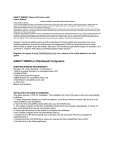
(2) Condition Window
Power loss conditions and results are displayed in the condition window.
① Target Device
② Device Data Profile
③ Modulation
④ Io (condition)
⑤ Calculation Results
①
Shows the target device name
Shows the thermal resistance of the target device.
The Rth(j-c) specification is the value per one IGBT switch, not per one
module. Only the IGBT switches in the inverter circuit are counted,
therefore the number given is “6” even for a 7 in 1 (with brake part)
module.
Modulation strategy selection.
3-phase PWM modulation for 3-Arm VVVF inverter;
2-phase PWM modulation for 2-Arm VVVF inverter;
Special operation such as chopper control or DC brake is also possible.
Inverter operating condition input.
Click “ ” on the tool bar to begin the calculation
②
⑤
③
④
Vcc
M
Rg
Iout
PWM pulse
Vout
1/fc
Io
ON
OFF
ton toff
duty =ton / (ton+toff)
Tf :heatsink temperature
φ
P.F =cosφ
Note: Rg input is not available for IPM, and duty input is only available for chopper calculation.
( 5 / 13 )