1
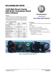
NCL30030GEVB
THEORY OF OPERATION
PFC
control rather than on time control or average current
control. CrM boost converters typically have fidelity issues
near the zero crossing of the AC line. This is a natural
consequence of parasitics in the power stage. See a typical
CrM inductor current in Figure 2.
The boost topology is the most common converter type for
high performance power factor correction. Since this boost
converter operates in CrM, the peak to average input current
is always a 2:1 ratio. The converter operates in peak current
Figure 2. Inductor Current across a Line Cycle
Near the zero crossings, the current starts below zero
current. This is a real effect of energy stored in the
capacitance of the FET drain that does not get transferred to
the output capacitor. The consequence for on time
controllers is that the target peak current is never reached in
the on time which results in distortion at the zero crossing.
Figure 3. One Switching Cycle of Boost Inductor Current (simulated)
Peak current control corrects the on time error because the
on time is dependent on the peak current. This will naturally
increase on time at the zero crossing which reduces total
harmonic distortion (THD).
The error amplifier adjusts the gain of a PWM multiplier
to set the peak current threshold in the controller. The
multiplier output needs to be filtered to recover the scaled
current threshold signal. The value of the filter capacitor is
critical to obtain good THD over the entire line range. The
filter capacitor must be large enough to filter the PWM
carrier frequency but not so large as to cause excess phase
lag which will degrade the THD.
www.onsemi.com
2