1
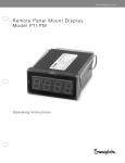
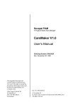
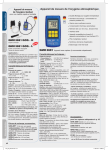
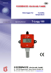
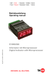
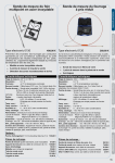
PAM & SAM
System User’s
Manual
Part 5 - SAM Drive
Technical Information
Ordering Number: 9032 011 985
Issue November 14, 2000
This version replaces all
previous versions of this
document. It also replaces
the SAM System Designer’s
Guide (1995-1996).
Inmotion Technologies and
ACC Motion have made
every effort to insure this
document is complete and
accurate at the time of
printing. In accordance with
our policy of continuing
product improvement, all
data in this document is
subject to change or
correction without prior
notice.
ACC Motion SA
Zone industrielle La Rippe
CH-1303 Penthaz
Switzerland
P/n 9032 011 985
Issue November 14, 2000
© 1995 - 2000
by ACC Motion SA
All rights reserved
PART 5 - SAM DRIVE TECHNICAL INFORMATION
PAM with SAM System Users Handbook
P/n 9032 011 985, November 14, 2000
TABLE OF CONTENTS
Page: 2
PART 5 - SAM DRIVE TECHNICAL INFORMATION
TABLE OF CONTENTS
Table of Contents
Table of Contents ...................................................................................................3
List of Figures .........................................................................................................4
List of Tables...........................................................................................................4
Hardware Functional Description............................................................................5
Introduction ..........................................................................................................5
Power Board........................................................................................................5
Control Board ......................................................................................................7
Brake Option Board .............................................................................................9
Specifications........................................................................................................11
Power Input and Output.....................................................................................11
Signal Inputs and Outputs .................................................................................12
Environmental....................................................................................................13
Physical Characteristics ....................................................................................14
Dimensions ........................................................................................................14
Page: 3
PAM with SAM System Users Handbook
P/n 9032 011 985, November 14, 2000
PART 5 - SAM DRIVE TECHNICAL INFORMATION
LIST OF FIGURES
List of Figures
Figure 1
Figure 2
Figure 3
Figure 4
Figure 5
SAM Drive boards assembly....................................................................5
Power Board functional diagram..............................................................6
Control Board functional diagram ............................................................7
Brake Option Functional Diagram..........................................................10
SAM Drive Unit Dimensions...................................................................14
List of Tables
Table 1
Table 2
Table 3
Table 4
PAM with SAM System Users Handbook
P/n 9032 011 985, November 14, 2000
SAM Drive Power input and output specifications .................................11
SAM Drive Signal input and output specifications .................................12
SAM Drive environmental specifications ...............................................13
SAM Drive weight specifications............................................................14
Page: 4
PART 5 - SAM DRIVE TECHNICAL INFORMATION
HARDWARE FUNCTIONAL DESCRIPTION
Hardware Functional Description
Introduction
Figure 1 shows the different assemblies that constitute a SAM Drive. The SAM
Drive functional description is organized according to the functions performed by
each board.
Power Board
Heat Sink
I/O Option Board
Control Board
Fan
Figure 1
Brake Option Board
SAH010_d.CDR
SAM Drive boards assembly
Power Board
General
Different Power Board designs are used for SAM Drives with different current
ratings; however, the functional operation of all power boards is identical. Figure 2
shows a functional diagram of the Power Board.
Page: 5
PAM with SAM System Users Handbook
P/n 9032 011 985, November 14, 2000
PART 5 - SAM DRIVE TECHNICAL INFORMATION
15 VDC
HARDWARE FUNCTIONAL DESCRIPTION
DC
24 VDC
DC
5 VDC
STOP1
STOP0
STOP0
Fatal Error
Servo_Ok
3 phases
PWM
Commands
IGBT
Drivers
IGBT
3 motor
phases
IGBT Fault
Currents
Measure
DC Bus
Image
Filter
Motor Temp
DC Bus
To/From External Devices
To/From Control Board
5V_Ok
STOP1
Motor Temp
(switch or PTC)
Heat Sink Temp
SAH011_c.CDR
Figure 2
Power Board functional diagram
24 VDC
An isolated DC/DC converter produces all input voltages required internally by the
SAM Drive from a single 24 VDC supply input. A voltage monitoring circuit detects
over and undervoltage and supplies a 5V_OK status input to the control board. A
5VDC failure immediately disables the IGBT drivers.
User Stop0 and Stop1
The USER STOP0 and USER STOP1 inputs are buffered and transmitted to the control
board. In addition, USER STOP0 immediately disable the IGBT preamplifiers. For
safety reasons they use “inverse logic”, which means that a zero voltage (no
current) activates the corresponding Stop function.
For additional information, see "Safety and Protective Functions”.
Fatal Error
The FATAL ERROR contact is closed only when the internal 5VDC supply is available
and no internal error condition exists. For additional information, see Part 3 “Safety and Protective Functions”.
IGBT Output Converter
An efficient three-phase four-quadrant IGBT output converter powers the axis
motor using DC power drawn from the DC Bus. During braking, kinetic energy is
fed back to the DC Bus where it is available to other axes. Power components are
mounted and thermally bonded to the heat sink. The heat sink mounting surface
temperature is monitored and, together with a software based power stage thermal
PAM with SAM System Users Handbook
P/n 9032 011 985, November 14, 2000
Page: 6
PART 5 - SAM DRIVE TECHNICAL INFORMATION
HARDWARE FUNCTIONAL DESCRIPTION
model, used to provide a warning when the computed transistor temperature
approaches the upper limit for reliable operation.
IGBT Fault
Sensors in the IGBT outputs measure motor current. Motor faults including phase
to phase shorts and shorts to ground are automatically detected and result in
immediate shutdown of the power stage by removing the current source to each
IGBT pre-amplification circuit.
DC Bus
The DC Bus is filtered and supplies the IGBT final stage. An image of DC Bus
voltage is transmitted to the control board. DC Bus voltage in excess of the
allowable limit triggers an immediate shutdown of the power stage.
Motor Temperature
Motor temperature signal from either a switch or a PTC resistor in the motor is
transmitted to the control board.
Control Board
General
Figure 3 shows a functional diagram of the Control Board. Different SAM Control
Board designs are used depending on the position feedback option; however, the
functional operation of all versions is identical.
24 VDC Image
Heat Sink Temp
STOP 1
Motor Temp
DC Bus Image
15 VDC Image
Power Board Interface
RS 232
Interface
EasyBus In
EasyBus Out
Fiber
Optic
Interface
Software
Watchdog
i960
Feedback
Interface
STOP 0
DSP
ASIC
PWM
Servo OK
3 Phase
PWM Command
SRAM
Current
Control
Current Measure
(2 phases)
Data/Address Bus
EEPROM
Fdbk
A
IGBT Fault
Hardware
Watchdog
SRAM
To / From Power Board
5V_OK
Ambient Temp
A
D
Fdbk
B
Sah012_d.cdr
Figure 3
Control Board functional diagram
Most SAM Drive functions are managed by one of two microprocessors, an i960
RISC processor for high level control and a DSP for motor control. An ASIC
Page: 7
PAM with SAM System Users Handbook
P/n 9032 011 985, November 14, 2000
PART 5 - SAM DRIVE TECHNICAL INFORMATION
HARDWARE FUNCTIONAL DESCRIPTION
(Application Specific Integrated Circuit) generates PWM signals for the power
board. PWM nominal frequency (8 kHz) can be adjusted to 4 kHz (higher output
power and lower thermal losses, but lower pass-band and louder acoustic noise).
A compressed version of the SAM Drive operating software and application
program along with uncompressed copies of a boot-up program, and all parameters
are stored in non-volatile EEPROM. Upon power-up the boot-up program is copied
into SRAM and executed. The boot-up program performs some hardware and
communications initialization, then copies the operating software (decompressed)
into SRAM.
Signals to/from Power Board
A warning (status bit) is set when 24VDC voltage approaches the lower limit for
safe operation. Should the voltage continue decreasing (i.e. due to failure to stop
the machine after a warning), the power stage is immediately shut down.
Heat Sink Temp inputs to a software-based power-stage thermal model that
provides a warning when the computed transistor temperature approaches the
upper limit for safe operation. Should the temperature continue increasing (i.e. due
to failure to stop the machine after a warning), the power stage is immediately shut
down.
Stop0 and IGBT Fault directly disable the PWM command signals
Undervoltage and overvoltage conditions on the +15 VDC internal supply are
detected and activate a Stop0.
Motor Temp - derived from a thermal switch or PTC in the motor - initiates a Stop0,
Stop1 or Stop2 depending on mask parameters defined by the user.
Temperature Sensor
A sensor monitors ambient temperature within the SAM Drive and provides a
warning when ambient temperature is greater than the upper limit for safe
operation. This can activate a STOP0, STOP1 or STOP2) depending on mask
parameters.
RS-232 Interface
RS232 interface handles communication with SAM Tools for SAM Drive setup,
testing and monitoring.
Fiber Optic Interface
The Fiber optic interface handles communication with the PAM over the EasyBus.
Communication failures and errors are detected and can initiate a Stop (STOP0,
STOP1, STOP2) depending on the setting of Mask parameters.
7 Segment Display
The 7 Segment display provides an indication of drive status and any existing error
conditions. Refer to the PAM and SAM System End-User Manual (p/n 9032 011
933) for detailed display information.
PAM with SAM System Users Handbook
P/n 9032 011 985, November 14, 2000
Page: 8
PART 5 - SAM DRIVE TECHNICAL INFORMATION
HARDWARE FUNCTIONAL DESCRIPTION
Feedback Interface
The Feedback Interface provides the necessary hardware and software for
interfacing to a SAM Drive any of the supported position feedback devices
including:
• Resolvers
• Sine-cosine encoders
• Multi-turn sine-cosine encoders with absolute position readout
Each SAM Drive is supplied with one of two possible Feedback Interface
configurations depending on the feedback option selected.
One option supports a single resolver; with the second option, two ports are
provided. One port accepts a resolver. The second port accepts a high-resolution
sine-cosine encoder or multi-turn sine-cosine encoder with ENDAT interface. User
parameters inform the SAM Drive operating software about characteristics of the
feedback device attached to the feedback port and the software configures the
interface hardware as required.
For resolvers, the conversion process provides 1/185,000 turn (7 arc-second)
resolution at speeds up to 8000 RPM with high dynamic performance. For sinecosine encoders, the conversion process provides resolution of 1/3550 encoder
period with total resolution dependent on the number of encoder periods per turn. A
regulated, 4 wire, 5 VDC power source enables 5 VDC sine-cosine encoders to be
operated over long feedback cables. The conversion software monitors the integrity
of the feedback signals and problems such as loss of signal and excessive noise
are detected and initiate a STOP0, STOP1 or STOP2 depending on mask
parameters.
Brake Option Board
The Brake Option Board (see Figure 4) is used for controlling an electromechanical
brake on a motor equipped with this option. The output is active (on) when the
power stage is enabled, and the SAM DRIVE controls motor position. It is inactive
(off) when the power stage is disabled for any reason (i.e. by command or STOP
0). To compensate for actuation time of an electromechanical brake, the brake
option can be adjusted (by parameter) to turn off brake current a short time before
the power stage is disabled.
The brake output is both open and short circuit protected. The condition of no
current flowing (as would occur with an open brake circuit) is recognized and
treated as an error condition. By default, a brake error bit generates a STOP0 (see
"STOP 0").
This same Brake Option may be used to control the contactor in a motor short
circuit braking circuit.
Page: 9
PAM with SAM System Users Handbook
P/n 9032 011 985, November 14, 2000
PART 5 - SAM DRIVE TECHNICAL INFORMATION
HARDWARE FUNCTIONAL DESCRIPTION
24VDC Ext
Undervoltage
Brake
Driver
Brake1
Brake2
Current
Limitation
Short-Circuit
Detection
Open Load
Detection
Diagnostic
_SBRA
SAH033_b.CDR
GND Ext
Figure 4
PAM with SAM System Users Handbook
P/n 9032 011 985, November 14, 2000
Brake Option Functional Diagram
Page: 10
PART 5 - SAM DRIVE TECHNICAL INFORMATION
SPECIFICATIONS
Specifications
Power Input and Output
SAM-DA-400
used at 400 VAC ± 10%
07
14
28
used at 480 VAC ± 10% (5)
50
07
14
28
50
DC Bus Voltage Input
Nominal value
[VDC]
570
minimum value (1)
[VDC]
0
680
0
maximum value
[VDC]
625
750
Output Current (3) (6)
ICONT @ 4 kHz
[ARMS]
8
15
28
58
7
15
24
56
IPEAK @ 4 kHz (2)
[ARMS]
13
34
49
84
12
33
46.5
79
ICONT @ 8 kHz
[ARMS]
6.5
15
20
34
6
15
16.5
30
IPEAK @ 8 kHz (2)
[ARMS]
10
28
38
62
8
26
34.8
56
Base losses @ 0 amps
[W]
30
30
30
30
30
30
30
30
Add. losses @ ICONT / 4 kHz
[W]
66
220
290
480
66
220
290
480
Add. losses @ ICONT / 8 kHz
[W]
66
220
290
480
66
220
290
480
Losses
24 VDC Supply Input
rated voltage
[VDC]
24
Tolerance
[VDC]
19.2 - 30.0 (including all AC components)
typical input current
[A]
0.8 (5)
max. input current
[A]
1.0 (5)
switch on current
[A]
2.5
Note (1)
Operation of a SAM Drive at DC Bus voltages down to zero VDC does
not constitute an error. However, maximum achievable motor speed
decreases with decreasing DC Bus voltage.
Note (2)
All SAM Drives are capable of operating at peak current (I ) for at
least two seconds. If the operating average (RMS)
current is less than rated current (I )or the
ambient temperature is less than max. permitted
value, the overload condition is permitted for a much
longer time. Thermal modeling performed by the SAM Drive
provides full protection.
PEAK
CONT
Page: 11
Note (3)
@ 4 kHz and @ 8 kHz, refer to the PWM frequency selected. Operation
at the 8 kHz PWM frequency with it’s higher pass band and lower
acoustic noise is recommended. In applications where lower pass band
and a higher acoustic noise level are acceptable, the higher output
power ratings at 4 kHz PWM frequency may permit selection of a
smaller (and lower cost) drive. A SAM Drive’s PWM frequency is user
selectable by parameter.
Note (4)
depends on the option(s) included in the unit
Note (5)
SAM-DA-400 drives can operate at 400 or 480 VAC supply, provided
that ProMotion 201 firmware is used. With previous firmware version,
operation at 480 VAC is not allowed.
Table 1
SAM Drive Power input and output specifications
PAM with SAM System Users Handbook
P/n 9032 011 985, November 14, 2000
PART 5 - SAM DRIVE TECHNICAL INFORMATION
SPECIFICATIONS
Signal Inputs and Outputs
SAM-DA-400- (all models)
User digital Inputs & Safety Inputs
(standard and high speed user inputs)
(STOP 0 & STOP 1 Safety inputs)
type
isolated 24 VDC input, type 2 (IEC1131-2)
VOFF
[VDC]
-0.3 - 5.0 @ 1 mA (max)
VON
[VDC]
15 - 30 @ 10 mA (typ)
on-off and off-on delay
[ms]
0.3 (typical) for high speed input, 10.0 (typical) for other inputs
User Digital Outputs
type
isolated 24 VDC output, protected against short-circuit, over-voltage and
polarity reversal
IOFF max
[mA]
0.4
ION max
[mA]
600 @ voltage drop = 2 V
on-off and off-on delay
[ms]
10.0 (typical)
User Analog Input
type
differential input, 12 bit resolution
input range
volts
accuracy
+/- 10.0
+/- 2% of reading
input impedance
ohms
10,000
sampling rate
[kHz]
2.0
Brake Control (Option)
type
isolated 24 VDC output; short-circuit, over-voltage and polarity reversal
protected
IOFF
[mA]
1
ION
[ADC]
2.0 (rated), 2.4 (max) @ voltage drop = 2 V
Fatal Error
type
floating contact, normally open, closed if no fatal error
max current
[A]
max voltage
1.0
60 VDC or 125 VAC
switch on/ switch off delay
[ms]
Motor Overtemp
2.0 (typical)
thermal switch or PTC
on/off transition
[Ω]
900 - 1800 (typ 1300)
hysteresis
[Ω]
100
Position Measurement Port A
Position Measurement Port B
See Part 2 - “System Design and Integration” for list of compatible position
measurement devices
Service Port
type
RS-422 full duplex
baud rate
[baud]
Table 2
PAM with SAM System Users Handbook
P/n 9032 011 985, November 14, 2000
19,200
SAM Drive Signal input and output specifications
Page: 12
PART 5 - SAM DRIVE TECHNICAL INFORMATION
SPECIFICATIONS
Environmental
SAM-DA-400- (all models)
Protection
protection degree
IP20 (IEC 529)
Ambient Temperature
operating
5 - 40ºC, air temperature below unit
extended range
5 - 55ºC with derating of power outputs and forced air circulation within
cubicle
daily avg. op. temp.
≤30ºC
transport and storage
-25...70ºC
Relative Humidity
operating
5...95%, occasional condensation
transport and storage
5...95%, occasional condensation, except at low temperature in order to
prevent the risk of damage by freezing.
Altitude
operating
≤1000m
extended range
≤2000m with derating of power outputs and forced air circulation within
cubicle
transport and storage
≤3000m
Climate
pollution
degree 2
operating
Class B3 (IEC 654-1) /3K4 (721-3)
transport and storage
Class 2K4 (721-3)
Shock and Vibration
high freq. vibrations
class V.H.4 (IEC 68-2-6), operating:
0.15mm constant amplitude (10 f 57)
2.0 g constant acceleration (57 f 150)
vibration severity
Class V.S.2 (IEC 68-2-6):
≤10mm/s
shocks
25 g / 10ms / XYZ, occasional (IEC 68-2-27), operating
free falls
1.0m / 5 times in 5 min. (IEC68-2-32), during transport
Table 3
Page: 13
SAM Drive environmental specifications
PAM with SAM System Users Handbook
P/n 9032 011 985, November 14, 2000
PART 5 - SAM DRIVE TECHNICAL INFORMATION
SPECIFICATIONS
Physical Characteristics
SAM-DA-400
04
07
14
28
50
3.8
3.8
6.9
7.1
13.9
Weight
[kg]
Table 4
SAM Drive weight specifications
Dimensions
Unit Dimensions - all Models
285
L
61
140
SAM-DA-400-07
SAM-DA-400-14 & 28
NOTE: Dimensions are in mm.
Figure 5
i
377
285
285
L
5
377
28
377
285
285
L
270
SAM-DA-400-50
SAH043_b.CDR
SAM Drive Unit Dimensions
For detailed mounting and interfacing dimensions see Part 2 - “System Design and
Integration”.
PAM with SAM System Users Handbook
P/n 9032 011 985, November 14, 2000
Page: 14