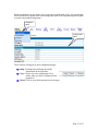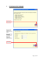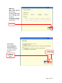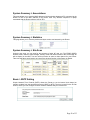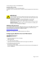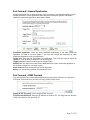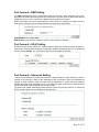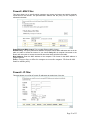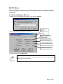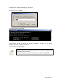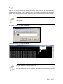
1
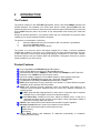
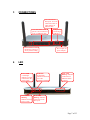
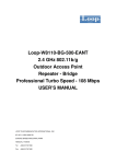
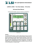
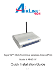
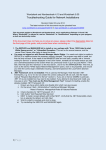
RFNET TECHNOLOGIES PTE LTD
USER MANUAL
RFNet 802.11g Wireless Router
With Wireless Network Storage Sharing
APRT-2801
Revision : 1-15
Updated: 04 Oct 2006
CONTENT PAGE
1
IMPORTANT NOTE .................................................................................................4
2
INTRODUCTION.......................................................................................................5
THE PRODUCT ....................................................................................................................5
PRODUCT FEATURES ..........................................................................................................5
2
PACKAGE CONTENTS ...........................................................................................6
CONTENTS OF PACKAGE ....................................................................................................6
SYSTEM REQUIREMENTS FOR CONFIGURATION .................................................................6
3
CONNECTIONS.........................................................................................................7
4
LED ..............................................................................................................................7
5
BASIC IP NETWORKING .......................................................................................8
WIRELESS LAN BASICS .....................................................................................................9
6
GETTING STARTED ..............................................................................................11
7
CONFIGURATION WIZARD................................................................................14
8
CONFIGURATION MENU ....................................................................................19
SYSTEM SUMMARY > CONFIGURATION............................................................................19
SYSTEM SUMMARY > ASSOCIATIONS ...............................................................................20
SYSTEM SUMMARY > STATISTICS ....................................................................................20
SYSTEM SUMMARY > SITE SCAN .....................................................................................20
BASIC > SNTP SETTING...................................................................................................20
BASIC > LAN SETTING ....................................................................................................21
BASIC > WAN SETTING ...................................................................................................21
BASIC > MAC CLONE....................................................................................................23
WIRELESS > BASIC SETTING ............................................................................................24
SECURITY > OPEN-SYSTEM/SHARED KEY ........................................................................25
SECURITY > WPA-PSK ...................................................................................................26
SECURITY > WPA............................................................................................................26
SECURITY > WPA 2-PSK ................................................................................................27
SECURITY > WPA 2 .........................................................................................................27
WIRELESS > ADVANCE SETTING ......................................................................................28
WIRELESS > MAC ACCESS CONTROL..............................................................................29
USB SETTINGS > BASIC SETTINGS ...................................................................................30
USB SETTINGS > USER SETTINGS ....................................................................................31
USB SETTINGS > SHARE SETTINGS ..................................................................................32
DHCP > DHCP SERVER ..................................................................................................35
DHCP > DHCP LIST .......................................................................................................36
PORT FORWARD > VIRTUAL SERVER ...............................................................................36
PORT FORWARD > SPECIAL APPLICATION........................................................................37
Page 2 of 55
PORT FORWARD > ICMP FORWARD ................................................................................37
PORT FORWARD > DMZ SETTING ....................................................................................38
PORT FORWARD > UPNP SETTING ...................................................................................38
PORT FORWARD > ADVANCED SETTING ..........................................................................38
FIREWALL > MAC FILTER ...............................................................................................39
FIREWALL > IP FILTER .....................................................................................................39
FIREWALL > URL BLOCKING.......................................................................................40
FIREWALL > ADVANCE ....................................................................................................41
MISCELLANEOUS > DYNAMIC DNS .................................................................................42
SYSTEM TOOLS > SYSTEM LOG .......................................................................................43
SYSTEM TOOLS > SYSTEM ADMIN ...................................................................................43
SYSTEM TOOLS > BACKUP/RESTORE SETTINGS ...............................................................44
SYSTEM TOOLS > FIRMWARE UPDATE .............................................................................45
SYSTEM TOOLS > REBOOT ...............................................................................................45
9
10
FACTORY RESET...................................................................................................46
PC CONFIGURATION .......................................................................................47
SETTING DHCP IP ADDRESS ...........................................................................................47
MY IP ADDRESS...............................................................................................................49
PING! ...............................................................................................................................51
WEB BROWSER SETTINGS ................................................................................................53
11
TECHNICAL SUPPORT.....................................................................................55
12
DISCLAIMER.......................................................................................................55
Page 3 of 55
1
IMPORTANT NOTE
1)External power supply for your external USB harddisk is recommended.
2)Regular data backup of your external USB harddisk is recommended.
Page 4 of 55
2
INTRODUCTION
The Product
The product is based on the IEEE 802.11g standard, which is the latest 54Mbps Wireless LAN
(WLAN) standard. This standard is five times faster than the widely deployed WiFi (802.11b)
products that are found in homes, airport and public wireless hotspots. Because 802.11g uses the
same 2.4GHz frequency band, the product is fully interoperable with existing WiFi cards and
devices.
Having two wireless protocols in one product ensure that your investments are protected, while
enabling you to enjoy the fastest Wireless LAN speed.
The product is a combination of 3 devices:
a.
Wireless LAN Access Point (AP) compliant to 802.11b and 802.11g standards.
b.
4-port Auto MDI/MDIX Switch
c.
Router with NAT, DHCP Server built-in.
The product is an all-in-one device that allows multiple PCs to share a common broadband
(ADSL/Cable) modem. It can serve up to 4 Ethernet-PCs and many WLAN-notebooks. The builtin NAT and DHCP Servers ensure almost plug-and-play convenience for your home network.
Advanced features such as Firewall, DMZ and WPA/WPA 2 Encryption make this a product
equally suitable for your office needs.
Product Features
Fully compatibility with IEEE 802.11g WLAN standard
Utilize OFDM (Orthogonal Frequency Division Multiplexing)
Wireless data rate of up to 54Mbps for APRT-2801G and 108Mbps for APRT-2801GS
Operates in the 2.4GHz license-free frequency band
Connects multiple computers to a broadband modem to share Internet connection
Equipped with 4 10/100 Ethernet ports and 1 WAN port, Auto MDI/MDIX
Full backward compatibility with 802.11b standard (WiFi 11Mbps)
WEP (Wired Equivalent Privacy) authorizes users based on a simple WLAN encryption
standard to protect wireless data from sniffers.
WPA (WiFi Protected Access) authorizes users and identifies users based on an
improved WLAN encryption standard where the secret key changes dynamically at
regular intervals
TKIP (Temporal Key Integrity Protocol), when used in conjunction with a corporate
RADIUS server, ensure higher security for enterprise networks.
Pre Shared Key, suitable for home user, without a RADIUS server. A new key is
generated each time the PC connects to the network, vastly improving the safety of
information exchange within the network
WPA 2 is the enhancement of WPA which uses the AES encryption algorithm.
Advance Firewall features to protect your network from the Internet.
NAT with VPN pass through to provide higher security.
MAC filtering
IP filtering
Built-in DHCP Servers that distributes IP addresses automatically to computers,
simplifying network setup.
Page 5 of 55
User-friendly web-based interface for managing and configuring the Router
Integrated USB 2.0 port allows plug-in storage device with:
• Data transfer speeds that are double that of 802.11g equipment.
• Long-range wireless transfer of bandwidth-intensive multimedia applications including
digital images, videos and MP3 files.
2
PACKAGE CONTENTS
Contents of Package
2.4GHz High Speed Wireless Router with attached Antenna
Power Adaptor-DC
User Manual
Quick Install Guide
Ethernet cable – 1m
Note: Using a power adaptor with a power rating other than the one included in the package will
cause serious damage to the Router and void the warranty for this product.
System Requirements for Configuration
Computers with Windows or Linux-based operating systems and with an Ethernet
adaptor
Internet Explorer version 5.5 and above or Netscape Navigator that supports Java.
Page 6 of 55
3
CONNECTIONS
Auto MDI/MDIX
WAN port. It is to be
connected to DSL or
cable modem via
Ethernet cable
Auto MDI/MDIX LAN
port. It is to be connected
to PC via Ethernet cable
Reset switch to restore
the Router’s setting to
factory default setting
4
USB port for
connecting a
USB drive
DC receptor for
power adaptor
LED
Power LED
A solid light
indicates a proper
connection to the
power supply
WLAN LED
Blinking:
Indicates wireless
LAN is ready
USB LED
A solid light
indicates connection
to a USB
thumbdrive/harddisk
LAN LED
Blinking: Indicates
connection to a
Ethernet-enable
computer
WAN LED
Blinking: Indicates
connection on the
WAN port
Page 7 of 55
5
BASIC IP NETWORKING
Internet Protocol (IP)
IP stands for Internet Protocol. In an IP network, every device has a unique IP Address (For
example: 192.168.1.35) to identify itself. There are two ways of assigning an IP address to a PC
or Router: Static and Automatic (DHCP). Static IP addresses are keyed-in manually, while
Dynamic IPs are distributed by a DHCP Server.
Ports
Every packet of traffic is identified by its Source and Destination Addresses, which would ensure
that the packet arrives at the correct destination. A Port Number is also embedded in each
packet; to identify which software application that generated and uses that packet. Therefore, if
the Router blocks a certain port number, it denies the particular software from using the
connection.
Static IP Address
Static IP addressing ensures that the device will always have the same IP address. Static
addressing is commonly used for your servers.
Dynamic IP Address
A dynamic IP address is one that is automatically assigned to a PC. These IP addresses are
“dynamic” because they are only temporarily leased to the PC when it connects to the network.
This is the most convenient and common way of managing IP addresses in a network. The
Server that manages this pool of IP addresses is called the DHCP Server. The product has a
DHCP Server built-in to simplify the network management.
DHCP (Dynamic Host Configuration Protocol)
The PC obtaining an IP address from the Server is called the DHCP Client. If there is already a
DHCP Server running on your network, you must disable one of the two DHCP servers. Running
more than one DHCP server together will cause network problems!
What is a Router?
A router is a network device that connects two networks together, to let them communicate. All
the PCs in your home or office would be considered to be in one network: the Local Area Network
(LAN). The Internet (including the ADSL modem) is considered to be another network: the Wide
Area Network (WAN). The Router serves 2 purposes:
Connect all the PCs in the LAN together, allowing them to communicate with one
another. (File sharing, Printer sharing etc.)
Connect all the PCs in the LAN to the Internet, allowing them to simultaneously surf the
web and access e-mails.
The Router is connected to 2 networks at the same time. Therefore, it has two IP addresses: one
for the LAN, and one for the WAN. The Router’s LAN IP address can be configured, but it is best
to use the default settings. The WAN port is a DHCP client by default.
Page 8 of 55
Wireless LAN Basics
A Wireless LAN (WLAN) is a computer network that transmits and receives data with radio
signals instead of using cables. WLANs have become common in homes, offices, airports and
public Hotspots. WLAN can support the same applications and software that run on a wired
network (LAN). Besides supporting the same software and functions, WLAN brings greater
convenience and eliminates the need to lay Ethernet cables in a home or office.
The Router is based on the finalised 802.11g standard. The IEEE 802.11g standard is an
improvement on the 802.11b (WiFi) standard. It increases the data rate up to 54 Mbps within the
2.4GHz band. As the 802.11b standard is also using the 2.4GHz frequency band, the product is
fully backward compatible with the older 802.11b devices. WiFi cards can be used to connect to
the Router at 11Mbps.
The Router can even support 108Mbps WLAN if the user is using a recommended Turbo-capable
Cardbus.
The Router is also known as the Wireless Access Point (AP). The PC using the Cardbus is
known as the Client. WLAN networking involves a few additional parameters to be configured:
SSID
The SSID is the “network name” for the WLAN network. The SSID is any name, and can be any
set of characters or numbers, and must be configured on both the AP and Client. The Client sniffs
the radio frequencies for an AP with the same SSID with itself. The client locks onto the AP and
they are “associated”.
To enable plug-and-play convenience, most client cards can sniff the frequencies to extract the
available SSIDs to let the user choose from. Alternatively, setting the client’s SSID to “ANY” can
allow it to connect to most APs regardless of the AP’s SSID setting.
Encryption
WLAN traffic can be captured by anybody to be read! The solution is to use encryption to make
the traffic appear as random characters to the eavesdropper. Both the AP and client must use the
same encryption standard and key to enable them to decode the “rubbish”. If the encryption
settings are mismatched, the client and AP cannot associate. WEP (Wired Equivalent Privacy) is
the most common WLAN encryption standard.
MAC Address Control
Every client card has a unique MAC Address. This MAC Address can be input into the AP
(Router), such that the AP only allows this pool of MAC Addresses to use the WLAN.
Channel
There are a total of 11 channels in the 2.4GHz band. Depending on regulation, not all the
frequencies may be available in every country. Frequency is configured on the AP only. The client
searches for the AP and locks onto that AP’s channel.
Signal Strength
Radio signals drop in power over a distance. Even if all the settings are correct, a low signal
strength makes association impossible. The usable distance between the AP and client can
range from a few meters indoor to 200m outdoors maximum. When setting up the AP, make sure
that you:
Page 9 of 55
Keep the distance from the AP to the clients as short as possible.
Make sure that the WLAN signals do not have to pass through too many concrete walls
and metal structures to reach the client.
Make sure that APs are located far away from one another to avoid interference.
Interference
Interference happens when 2 APs with the same channels are placed near to one another. The
speed of the network drops and the signal strength fluctuates wildly.
Roaming
Association happens when the SSID, Encryption and MAC Address Control settings are correct
between the AP and client. If 2 APs with these same settings are located in the same area, the
client would choose to associate to the one which gives it a better signal strength. The client
would roam over to the 2nd AP when he moves nearer to it. The client switches AP and
frequency as he does so.
Page 10 of 55
6
GETTING STARTED
The router is connected to the WAN and LAN networks.
WAN
Internet
LAN
Modem
Router
The cables are all connected to the back-panel of the Router. The PCs and Modem are
connected to the Router via Ethernet cables. Take note that the head of the Ethernet Cable looks
similar to a phone connector but is bigger. Your notebook can also be connected to the Router by
installing and plugging in the CardBus Card on your notebook.
Note : USB print sharing feature is an optional upgradeable features.
Modems that connect using a USB cable cannot be used.
Use only modems that have Ethernet connectors.
USB Modem
Ethernet connector
Page 11 of 55
To access the Configuration menu of the Router,
connect the router as shown in the previous section.
Open the web browser.
Type the Router’s default IP address (192.168.1.20)
into the browser’s Address field.
Note: If you have changed the default IP of the Router, make sure you enter the correct IP
address.
Type in admin for user name.
Type in admin for the password.
Click on Log In.
Note: If you have changed the default user name and password of the Router, make sure you
enter the correct user name and password.
Once the login is successful, you’ll see a configuration menu and a pop up window for wizard
setup. The wizard is a quick guide to run you through the configuration process so as to setup
your system in the shortest time. After the initial setup, you may wish to turn off the setup wizard
by removing the tick on Run This Wizard At Start. Click on Next to proceed with the setup wizard.
Note: If you have pop-ups blocker installed on your computer, it may prevent the Wizard window
from functioning properly.
Page 12 of 55
Detailed configuration for the Router can be found at the configuration menu. The Configuration
menu consists of a navigation menu and a configuration panel. The configuration panel is a place
to set the entire detailed configuration.
Navigation
panel
Configuration
panel
These buttons will appear at most configuration pages.
Help: Clicking help will bring up helpful
information on the functions.
Save: Click to save the configuration. Do a
reboot when you have configured all the
parameters.
Reset: Click to reset all the parameters on the page.
Page 13 of 55
7
CONFIGURATION WIZARD
Click Next
Once you have
logged in, the
Wizard screen will
appear.
Set up your new
password
The default User
Name and
password is
admin and admin.
Click Next
Page 14 of 55
Choose your Time
Zone
Enter the SNTP
Server. If you do not
know of any SNTP
Server, you can use
the default.
Choose your time
zone from the drop
down list.
Click Next
Select your Internet
connection
- For DSL user, choose
PPPoE.
- For Cable user,
choose Dynamic
- Choose Static
connection only if
your ISP provide you
with the IP address,
subnet mask,
gateway and DNS
server IP address.
Click Next
Page 15 of 55
If your ISP requires
static IP and you
have chosen this
option, this screen will
appear.
Enter the IP address,
network mask,
gateway address,
DNS server IP
address as provided
by your ISP in the
relevant fields.
Click Next
If you are a DSL user
and you have chosen
PPPoE option, this
screen will appear.
Enter the user name
and password
provided by your ISP.
Click Next
Page 16 of 55
Wireless Setup
Enter the SSID you
preferred for your
network.
You can manually
select the channel
you wish to use or
allow the Router to
select a clean
channel to use by
selecting
SmartSelect.
Click Next
Wireless Security
Enter the type of
security mode you
wish to use. Take
note that if you are
using a 802.11b
card, it does not
support WPA-PSK
or WPA or WPA 2PSK or WPA 2
Click Next
Page 17 of 55
USB Setup
Enter name of the
server & the name of
the workgroup.
The server name seen
on the network & the
PC is a member of the
workgroup.
FTP access is enabled
or disabled for the login
account listed.
Click Next
End of Setup
Click on Reboot to
save the setting and
reboot the Router. If
you wish to discard all
the setting, click on
Discard.
Click Discard to
cancel all settings
Click Reboot to
finish the setup
Wizard
Page 18 of 55
8
CONFIGURATION MENU
System Summary > Configuration
This page presents a convenient overview of the overall status of the Router. The most common
configuration parameters are shown here, for a quick look.
(18dBm)
Page 19 of 55
System Summary > Associations
This page allows you to view the MAC address of all the wireless laptop and PC connected to the
Router. ID AP is the MAC address of the Router itself. Any wireless computers or laptop
associated with the Router will have a ID of STA.
System Summary > Statistics
This page allows you to view the packets and bytes receive and transmit by the Router.
System Summary > Site Scan
Using the site scan, you can scan for the presence of other AP near you. The ESSID, BSSID,
wireless mode, channel, signal strength, security mode and network mode of the surrounding AP
will be display in the table. You can use this function to select a clean channel for your Router.
Take note that there would not be any result if the wireless function of the Router is disable.
Basic > SNTP Setting
Simple Network Time Protocol (SNTP) allows the Router to set its internal clock based on
periodic updates from the specified timeserver (SNTP or NTP). The time is useful in the IP filter
section, where you can configure to block certain IP address daily at a certain time.
Page 20 of 55
Basic > LAN Setting
This page is for the configuration of the Router’s internal (LAN) IP Address.
System Name: This is to assign a name to the router so that you can identify the Router.
LAN IP address: This is where you assign a local IP address to your router’s LAN port. The
factory default value is 192.168.1.20. If you give your computer a static IP address, the gateway
of your computer must be set to this IP for you to access the Internet.
Subnet Mask: This is where you assign the corresponding subnet mask. The default subnet
mask is 255.255.255.0.
(Note: When you change the LAN Setting of the Router, you need to reset/renew the Local computer IP address.)
Basic > WAN Setting
This page allows you to configure how the WAN is connected. For ADSL modem users, you have
to use PPPoE. If you connect the WAN to an existing Ethernet network, you have to set either
Static WAN or DHCP Client. The default setting for the router is in DHCP Client mode.
Dynamic WAN
When using dynamic WAN, the Router will automatic request for IP address, network mask,
gateway address and DNS server from the network. The acquired IP addresses will reflect in the
relevant fields. You can choose to manually set the DNS server if you know the IP address of the
DNS server. Typically, cable modem users will be using this option.
Page 21 of 55
Static WAN
You can choose to manually set all the fields if your ISP or network provides you with the IP
address, network mask, gateway and DNS. Do take note that the IP addresses in each field must
be of the appropriate format (xxx.xxx.xxx.xxx). The Router will not accept the IP address if it is not
in the correct format.
PPPoE Type
Select this option if your ISP requires you to use a PPPoE connection. Typically, users with DSL
connection would require this option.
Page 22 of 55
IP Address: This displays the IP of your WAN as given by the ADSL modem.
Network Mask: This displays the network mask of your WAN as given by the ADSL modem.
Gateway Address: This displays the gateway address of your WAN as given by the ADSL
modem.
DNS Server: This displays the IP address of the DNS server as given by the ADSL modem. You
can manually set the DNS server if your ISP provides you with the IP address of the DNS server.
Secondary DNS: This displays the IP address of the secondary DNS server as given by the
ADSL modem. You can manually set the secondary DNS server if your ISP provides you with the
IP address of the secondary DNS server.
Username: Enter the username given by your ISP.
Password: Enter the password given by your ISP.
MTU: Maximum Transmission Unit indicates that packets larger than this size will be fragmented
before the transmission. Enter an MTU value only if required by your ISP. Otherwise, leave it as
the default setting.
Manual: You will only be connected or disconnect to the Internet when you click on the Connect
and Disconnect button.
Always on: The Router will auto-connect with the ISP when it restarts or when the PPPoE
connection is dropped.
Connect on Demand: Router will auto-connect to ISP when user launches any program that
require Internet connection on his PC.
Idle Time before auto-disconnect: You can set the Router in such a way that it will disconnect
after a certain period of inactivity. The time can be set in this field.
Basic > MAC CLONE
The default WAN MAC address is set to the WAN’s physical interface MAC address on the
Router. You can use the MAC Clone function to replace the default MAC address to that of the
Ethernet Card installed by your ISP. It is not recommended that you change the default MAC
address unless required by your ISP.
Enable MAC Clone: Tick to enable MAC Clone function.
MAC Address: Enter the MAC address you wish to clone or use the default MAC by
clicking on the Use Default MAC button.
Your PC MAC Address: This field reflects the MAC address of your computer.
Page 23 of 55
Wireless > Basic Setting
This page lets you configure the Wireless settings of the Router. There are 2 sections: Radio and
Security.
Enable Wireless: Tick to enable wireless function. With this function, laptop with cardbus or inbuilt wireless function can access the Router wirelessly.
SSID: Service Set Identifier. It is a sequence of characters that uniquely names a Wireless LAN.
This name allows PCs to connect to the correct Wireless Access Point when multiple Access
Points (or Wireless Routers) operate in the same location.
Channel: The radio channel number. You can select channel 1 to 11 or use SmartSelect, where
the Router will select the cleanest channel to use upon booting up. The number of channels
varies according to countries.
SSID Suppressed: When SSID is suppressed, the router will not broadcast the SSID.
Unwelcome PCs will not be able to scan for the SSID of this Router, and they can only associate
if they know exactly what is the SSID.
Wireless Mode: You can choose to operate the Router in 802.11g or 802.11b mode. The data
rate for 802.11g is 54Mbps while the data rate for 802.11b is 11Mbps. 802.11g is backward
compatible with 802.11b.
You will be able to select Dynamic Turbo or Static Turbo Mode. Turbo mode operates in
108Mbps. For Dynamic Turbo, it can operates in the data rate of 108Mbps & below. In Static
Turbo, it can only operates in the data rate of 108Mbps. But throughput would be reduced if there
are many interferences using Turbo mode operation.
Security Mode: This section allows you to configure wireless encryption to prevent unwelcome
parties from reading your traffic. You must Enable the Security Mode before choosing the type of
wireless security.
Page 24 of 55
Security > Open-System/Shared key
Open-System: When chosen, the Key is not used for authentication. It is only used for
encryption. Open-System uses Static Keys for encryption. Static (Shared) Keys are never
changed, and a hacker can crack the key after a period of time.
Shared-Key: When chosen, the encryption Key is also used for authentication between the
Router and Client. Note that this system is also using Static Keys.
Key Entry Method: Choose HEX if you want to enter the Keys in hexadecimal format. Otherwise,
enter in ASCII format. ASCII is also called Alphanumeric in some systems. Use the same key
format for the Router and Client!
Key 1-4: The Key is to be entered in the boxes. The SAME Key must be entered in both the
Router and Client. Take note that there is a different Key length for a different number of
encryption bits. 152 bits is the most secure, but make sure that your Client card supports it. The
last point to take note is that if you use Key 4 on the Router, you must also use Key 4 on the
Client, for example. The same logic applies for Keys 1-3.
Page 25 of 55
Security > WPA-PSK
WPA-PSK is also known as WPA-Preset-Key. This implementation is more secure than WEP as
the encryption is automatically changed periodically. To configure this feature, just key in a 8-63
ASCII character or 64 HEX character pass-phrase for both the Router and Cards.
Cipher: You can choose to use TKIP or AES for the cipher type.
Security > WPA
WPA (WiFi Protected Access) is a standard where the Wireless Card has to authenticate to a
RADIUS Server, through the Access Point. The Server can also manage the encryption keys
such that they are changed dynamically. You need to have a RADIUS Server to be able to use
this feature.
RADIUS Server: Enter the IP Address and the port of the RADIUS Server.
Shared Secret: Enter the Shared Secret of the RADIUS Server.
Confirm Source: Enter the Shared Secret again to confirm.
Page 26 of 55
Security > WPA 2-PSK
WPA-PSK is also known as WPA-Pre-Shared-Key. This implementation is more secure than
WEP as the encryption is automatically changed periodically. To configure this feature, just key in
a 8-63 ASCII character or 64 HEX character pass-phrase for both the Router and Cards. WPA 2PSK is the enhancement of WPA-PSK which uses the AES encryption algorithm.
Cipher: You can choose to use TKIP or AES for the cipher type.
Security > WPA 2
WPA (WiFi Protected Access) is a standard where the Wireless Card has to authenticate to a
RADIUS Server, through the Access Point. The Server can also manage the encryption keys
such that they are changed dynamically. You need to have a RADIUS Server to be able to use
this feature. WPA 2 is the enhancement of WPA which uses the AES encryption algorithm.
RADIUS Server: Enter the IP Address and the port of the RADIUS Server.
Shared Secret: Enter the Shared Secret of the RADIUS Server.
Confirm Secret: Enter the Shared Secret again to confirm.
Page 27 of 55
Wireless > Advance Setting
This page allows you to configure the advance wireless setting of the Router.
Data Rate (Mbps): You can set the wireless data rate from the available list or choose Best to
allow the Router to choose the most appropriate data rate. When Best is used, the Router will
determine the optimal data rate according to the environment.
Transmit Power: This adjust the transmit power of the antenna. Sometimes, it is useful to
decrease the coverage range of each Router, so that more Routers can be located together
without interfering one another.
Preamble: Choose Short Preamble or Long Preamble. Most manufacturers implement long
preambles. Even if there is a mismatch between the Router and the card, they can still connect
well and the mismatch may not be noticeable to most users. Do not change this setting without
seeking advice.
Slot Time: Choose short or long slot time. The slot time is the amount of time a device waits
after a collision before retransmitting.
Protection Mode: Select None, Always or Auto.
Protection Type: Select either CTS only or RTS-CTS.
RTS/CTS Threshold: Request to Send/Clear to Send.The primary use of RTS/CTS is to
minimize collisions among hidden stations. Forcing the access point to implement the RTS/CTS
handshake will significantly increase the overhead and reduce throughput. Once the RTS/CTS is
set at the station, it initiates by sending a RTS frame. Upon receiving, the access point will
responds by sending a CTS frame. Select the RTS/CTS radio button to enable this feature. Set a
packet size threshold (256 ~ 2347 bytes) value to trigger this protection. If the packet that the
station/access point is transmitting is larger than the threshold, it will initiate the RTS/CTS
function.
Page 28 of 55
Wireless > MAC Access Control
This page allows you to specify which wireless computer can access the Internet and which
wireless computer cannot access the Internet. The specified MAC address and the policy for the
computer are reflected in the table.
Enable Wireless MAC Control: Tick to enable Wireless MAC Control.
Default Policy: This policy determines whether computers, whose MAC addresses are not in the
table, are able to access the Internet. If you choose Deny All, all computer associated to the
Router will not be able to access the Internet other than those specified in the table.
MAC Address: Enter the MAC address of the computer. The format for the MAC address is
aa:bb:cc:dd:ee:ff.
Policy: Choose to deny or allow the computer to access the computer. Click on the Add button to
add the policy.
Page 29 of 55
USB Settings > Basic Settings
To configure the USB drive settings, click the USB Settings link in the main menu of the browser
interface. The USB Settings screen appears, as shown below.
Network Access
• Server Name. The name of the USB server in the network. User use it to access the attached
USB devices.
• Workgroup. The name of workgroup that the USB server is a member of.
FTP Access
• Status. Access is enabled or disabled for the login account listed.
• Login Name. The name for user to access USB FTP server.
• Password. The password for user to access USB FTP server.
• Device ID. The ID of the attached USB device to be used for FTP access.
• Partition ID. The ID corresponding to the logical drive ID of above USB device indicated with
deviceID.
Note : Once the drive is attached to the USB port of router, FTP will be possible.
Page 30 of 55
USB Settings > User Settings
The USB Settings screen shows which login accounts are enabled. The following fields are
displayed
User to be added
• Username. Type in your login username.
• Password. Type in your login password.
• Retype Password. Re-type your login password for validation.
• Add. Click ADD will update the username and password informations into the User List.
• Delete. Click Delete will delete the username and password informations from the User List.
User List
• User ID. The list of allowed users to access the usb drive.
Page 31 of 55
USB Settings > Share Settings
The screen shows the configuration of the USB share settings for the USB device attached. The
following fields are displayed :
Attached Device
• Index. The index number on the USB drive.
• Product. The name of the attached USB drive.
• Device ID. The ID of the attached USB drive.
• Partition ID. The ID corresponding to the logical drive ID of above USB device indicated with
deviceID.
• File System Type. The file system on the partition can be FAT16, FAT32, NTFS (read only), or
Linux.
• Share. Click ADD will add the logical drive indicated by DeviceID and PartitionID for share with
default share path as /.
Share To Be Edited
• SharePath. The path of the folder to be shared with default share path as /.
• ShareName. The name given for the folder to be shared.
• Share. Click Update will update the changes in the SharePath & ShareName into the list of
Share Service.
Example
SharePath
/
/ temp
ShareName
usbDisk1_0
usbDisk1_0
Meaning
Share the whole drive
Only share the folder : temp
Note : This is a security feature to choose not to share the whole disk
Share Service
• Edit Delete. Click Edit/Delete will allow the list of informations to be edited/deleted in the Share
To Be Edited settings.
Changes to take Effect
After you have made all your changes, click the Refresh button to apply your changes.
Page 32 of 55
To set all settings to default, click the Reset button.
Copy/Delete Data from Disk
To copy/delete data from a disk, use windows explorer.
Copy/Delete. Click the copy/delete button to initiate the required copying/removal of data from the
disk.
IMPORTANT:
1) User must NOT disconnect the USB disk while data is being transferred to or from
the disk; otherwise, data may be lost. It may also result in file or disk corruption. Wait
for the action to e completed.
2)External power supply for your external USB harddisk is recommended.
3)Regular data backup of your external USB harddisk is recommended.
4) Ensure power up of USB drive for a while first before presence of the drive can be
detected by the router.
5) Need to refresh the configuration page to acquire the lattest drive availability after
connecting or disconnecting from the USB port.
USB Drive Requirements
The 108 Mbps Wireless Combo Router APRT-2801 would only work with USB-compliant external
flash and hard drives. For the lattest list of USB drives supported by the APRT-2801 combo
router, user would need to check with our websites as follows :
http://www.rfnetech.com/user1.htm
Important : Do not attempt to use a USB hub attached to the USB port.
Configuring the USB Drive from Local Web browser
1. Type http:\\ followed by the router’s IP address :
http:\\192.168.1.20
2. Go to USB settings/user settings :
Type the account name and password that has access rights to the USB drive.
3. Go to USB settings/advanced settings :
Click ADD in the attached device
The root directories of the USB drive that the login account has access to will be displayed, for
example: \\usbDisk_0\
Page 33 of 55
Accessing the USB Drive from the Windows Start Menu
To access the USB Drive using Microsoft network connections :
Click Windows Start > Run and type: \\aprt-2801
The name entered is the host name of the router.
A new Explorer window will pop up displaying the root folders your account has access to.
Accessing the USB Drive from Windows Explorer or network
places
In Network Places, type : \\aprt-2801
It will display the root folders granted access to on the USB drive.
Accessing the Router’s USB Drive Remotely Using FTP
User is recommended to access the router’s USB drive remotely using the FTP program and not
the web browser.
You can connect to the router’s USB drive using a FTP program :
1. Connect to the router by typing the router Internet port IP address in the address field of
FTP program.
2. Type the account name and password that has access rights to the USB drive.
3. The directories of the USB drive that your account has access to will be displayed. You can
now read and copy files from the USB directory.
Page 34 of 55
DHCP > DHCP Server
This page is to configure the properties of the Router’s built-in DHCP Server. Take note that the
built-in DHCP Server distributes IP Addresses to both the LAN ports and the WLAN clients.
Enable DHCP Server: Tick to enable the built-in DHCP (Dynamic Host Configuration Protocol)
Server. When enabled, the Router will provide IP addresses to the computers connected to the
router.
IP Address pool: When ‘System Define’ is selected, router will assign IP address automatically
from the pre-defined pool. If ‘User Define’ is selected, you would have to define the range of the
pool manually.
IP Address pool (For User Defined only), Start Address: This is the start address of the DHCP
pool. The router will assign this to the first computer connected to the router.
IP Address pool (For User Defined only), End Address: This is the end address that the router
will assign to the computers connected to the router.
Lease Time: The amount of time a network computer will be allowed to connect with the DHCP
Server. By default, the lease time is 2880 minutes.
DHCP Server Reserved Entries: This feature allows you to reserve up to 8 LAN IP Addresses.
These addresses can be assigned to your Servers, so that they always get the same IP Address
when they boot up. Fill up the table by order of ID.
ID: Tick to enable this reservation.
MAC Address: Enter the MAC Address of the Server, so that the Router can identify your Server
properly. The format for the MAC address is aa:bb:cc:dd:ee:ff.
IP Address: Enter the IP Address that you want to reserve for your Server.
Page 35 of 55
DHCP > DHCP List
This is a log showing all the IP assigned to the computer by the Router in the WLAN and LAN
ports. The table will display the MAC address of the computer with the corresponding IP address.
Port Forward > Virtual Server
This page allows you to configure Virtual Server. This feature is used when you need to allow
computers from the Internet to access servers in LAN. Traffic initiated from the WAN (Internet) is
normally blocked. Virtual Server allows the specific type of traffic to pass through the Router to
reach the Server in the LAN. Examples of these Servers are Web Servers and Game Servers.
Protocol: Select the type of protocol to be forwarded. Choose between TCP and UDP.
Local IP Address: Enter the IP address of the Local Server.
Local Port: Enter the port value on the LAN side.
Global Port: Enter the port value on the WAN side.
Status: Choose to activate or deactivate this rule.
Click Add button to add the rule. The rules will be listed in the table. You can amend the rules in
the table by clicking on Edit or delete the rules by clicking on Delete. Click Update button when
amending the rule in the table.
Page 36 of 55
Port Forward > Special Application
Certain applications such as Internet gaming, video conferencing, and Internet telephony require
multiple connections. These applications have difficulties working through NAT and Special
Application make these applications work with the Router.
Predefined Application: There are some predefined applications in the table. Select the
application you want to use and enable it. You may also change the parameters of these
predefined applications to suit your application.
Trigger Port: Enter the port associated to the application. This is the port used to trigger the
application. It can be either a single port or a range of ports.
Trigger Protocol: Enter the protocol type for the application.
Public Port: This is the port number on the WAN that will be used to access the application. It
can be either a single port or a range of ports.
Public Protocol: Enter the protocol type for the application.
Status: You can choose to activate or deactivate the entry.
Port Forward > ICMP Forward
You can forward Ping (a network troubleshooting tool) from the Internet to a specified
LAN host. If the host exits, the host will reply to the ICMP sender.
Enable ICMP Forward: Tick to enable ICMP forward.
ICMP Forward Host IP: Enter the IP address of the Host PC. All Ping from the Internet
will be forwarded to this specified PC.
Page 37 of 55
Port Forward > DMZ Setting
The DMZ (De-Militarized Zone) Configuration page lets you map a local computer to this zone.
By default, the Router protects the PCs from the Internet. The local PCs can access the Internet
(WAN) but not vice versa. Local PCs are hidden behind the NAT and Firewall.
DMZ is used when you want to expose that PC to the Internet. For example, you want to set up a
Web Server or Game Server such that outsiders can access from the Internet.
Enable DMZ: Tick to enable DMZ.
DMZ Host IP: Enter the local computer's (Web or Game Server) IP address.
Port Forward > UPnP Setting
Universal Plug and Play (UPnP) is a network feature utilizing the Internet and Web protocols to
promote the communicative exchange of information between networking devices. To enable this
function, choose Enable. The current UPnP NAT list will be display in the table.
Port Forward > Advanced Setting
(Virtual Private Network) A private network that is configured within a public network (a carrier's
network or the Internet) in order to take advantage of the economies of scale and management
facilities of large networks. VPNs are widely used by enterprises to create wide area networks
(WANs) that span large geographic areas, to provide site-to-site connections to branch offices
and to allow mobile users to dial up their company LANs.
The feature will enable transmitting packets with one of two VPN security protocol i.e. IPSec and
PPTP, so that LAN PC can access WAN pc through VPN .
Page 38 of 55
Firewall > MAC Filter
This page allows you to specify which computer can access the Internet and which computer
cannot access the Internet. The specified MAC address and the policy for the computer is
reflected in the table.
Enable Ethernet MAC Control: Tick to enable Ethernet MAC Control.
Default Policy: This policy determines whether computers, whose MAC addresses are not in the
table, are able to access the Internet. If you choose Deny All, all computer connected to the
Router will not be able to access the Internet other than those specified in the table.
MAC Address: Enter the MAC address of the computer. The format for the MAC address is
aa:bb:cc:dd:ee:ff.
Policy: Choose to deny or allow the computer to access the computer. Click on the Add
button to add the policy.
Firewall > IP Filter
This page allows you to filter off certain IP addresses at certain time of the day.
Page 39 of 55
LAN IP: Enter the LAN IP address that would be denied access to the Internet. It can be one IP
or a range of IP.
Port: The single LAN port or port range that will be denied access to the Internet.
WAN IP: Enter the WAN IP address that would be denied access to the Internet. It can be one IP
or a range of IP.
Port: The single WAN port or port range that will be denied access to the Internet.
Protocol:
Schedule (Always): Choose this to keep the filter rule always on.
Schedule (Start time): The time when you would like to start blocking the IP Address.
Schedule (Stop time): The time when you would like to stop blocking the IP Address.
Status: Choose to activate or de-activate the filter rule.
Firewall > URL BLOCKING
URL Blocking is used to deny LAN computers from accessing specific websites by blocking the
URL. If any part of the URL contains the blocked word, the site will not be accessible and the web
page will not be display.
Enable URL Blocking: Tick to enable URL blocking function.
URL Keywords or Domain: Enter the keywords or the domain that you want to block.
Status: Choose to activate or de-activate the blocking rule.
Note : This feature is for parental control.
Page 40 of 55
Firewall > Advance
Block SynFlood: SynFlood is a virus that sends multiple Syn packets to a host, occupying a
large memory space of the Router. To prevent this, check this option.
Block Java: Some Java applications embedded in the web pages may be harmful to the
computer system. You can check this to block these Java files or scripts. However, do take note
that some web pages that requires java files might not function properly when this option is
checked.
Block ActiveX: ActiveX is a tool for building active web pages. When you visit an ActiveX web
page, ActiveX controls are downloaded to your browser, in case you visit the site again. You can
block these ActiveX controls by checking this option. However, do take note that some ActiveX
web pages might not function properly when this option is checked.
Block Cookies: Many web services use cookies track usage and authenticate users. These
cookies are stored in your browser in case you visit the site again. You can block these cookies
by checking this option.
Block Proxy: Check this to block Proxy. If your network requires a proxy server, it would affect
your Internet connection.
Disable Web Access from WAN: This feature prevent anyone from accessing the Router’s
configuration page from the WAN port. For security reason, it is best to keep this option check.
Flux Shaping: Forwarding broadcast or multicast packets can lead to severe storms of packets,
and if uncontrolled could lead to network overload. To prevent this from happening, user can set
the maximum number of packets or bytes of flux which router forward from Wan to Lan per
second.
Note : All these blocking securities are against virus attacks to your system but some websites
may need these tools and need to be enabled to access the websites.
Page 41 of 55
Miscellaneous > Dynamic DNS
Dynamic DNS allows you to update your current dynamic IP address with dynamic DNS services
so that you can be contactable most of the time. You can also access your FTP server or web
page on your own computer using a domain name. Unlike IP address, the domain name will not
change with each reconnect.
First of all, you would need to register a dynamic DNS account dynamic DNS service provider.
The Dynamic DNS service provider will give you a password.
Enable DDNS: Tick to enable dynamic DNS.
DDNS Server: There is a few default DDNS server in the drop down menu;
http://www.dyndns.com/, http://www.no-ip.com/, http://freedns.afraid.org/.
Host Name: Enter the host name registered with the dynamic DNS service provider.
User Name: Enter the user name registered with the dynamic DNS service provider.
Password: Enter the password registered with the dynamic DNS service provider.
Verify Password: Verify the password registered with the dynamic DNS service provider.
Use a Proxy Server: Tick this option if your network is using a proxy server.
Address/Port:
Address
and
port
of
the
proxy
server.
Page 42 of 55
System Tools > System Log
This page allows you to configure the Router to dump its status to a System Log Server.
Enable Remote System Log: Enable this feature to allow the Router to constantly update its
status on a System log Server.
System Log Server IP: Enter the IP Address of the System Log Server if you had enabled
Remote Logging.
System Log Server Port: Enter the port number the System Log Server is using.
Enable Local System Log: Enable this feature if you do not have a System log Server. The
events would then be logged locally on the Router.
Log Management when log is full (Stop Logging): When this option is chosen, the Router will
stop logging.
Log Management when log is full (Auto Delete): The maximum number of local log entry is
200. When all the 200 entries are used up, the Router will overwrite previous entries with new
logs.
Remember to Apply and Reboot for the settings to take effect.
System Tools > System Admin
This page allows you to change the Administrator’s Username and Password. The default
username and password is admin / admin. After every Factory Reset, the Router reverts to this
combination.
Page 43 of 55
System Tools > Backup/Restore Settings
Use this page to preserve any good setting. You can save the configuration file into your
computer and upload it back to the Router when the setting of your Router when
necessary. In addition, you can do a factory reset and restore the Router back to factory
default setting. The factory default setting is shown in the Factory Reset section.
Page 44 of 55
System Tools > Firmware Update
This page allows you to update the firmware (software) in the Router. New firmwares are issued
to improve the performance and add features to the product.
1. The new firmware is a file name “apimg1”.
2. Save the file in your PC.
3. Browse and select the firmware file.
You will see the following page when firmware upgrading is successful.
Do not close the browser or shutdown the Router during firmware upgrading.
Failure to do so will cause serious damage to Router.
System Tools > Reboot
This page allows you to reboot the Router. You must reboot the Router after you have finished
configuring the Router for the new setting to take effect.
Page 45 of 55
9
FACTORY RESET
When you have wrongly configured the Router and wish to start all over again, you can perform a
Factory Reset to restore the Router to its original state. Power up the router and simply use a
paper clip or any pointed object to press in the hole on the back of the router for 10 seconds and
release.
The Router would be reset to its original Factory Default configuration:
Router’s Feature
User Name
Password
WAN IP
WAN subnet mask
LAN IP
LAN subnet mask
DHCP Server (including WLAN)
SysLog
SSID
Channel
MAC Address Control
Wireless Security
DMZ
Virtual Server
Network Access - Server name
Network Access - Workgroup
FTP Access – login name
FTP Access – password
IP Filter
Factory Default
admin
admin
192.168.1.20
255.255.255.0
On.
Local System logging on
11g
SmartSelect
Off
Off
Off
Off
APRT-2801
Workgroup
Combo
Combo
Off.
Page 46 of 55
10
PC CONFIGURATION
The Router’s function is to connect multiple PCs to the Internet. In addition to configuring the
Router, the PCs’ IP settings would also need to be configured.
It is easiest to use DHCP client for the PCs. This is also the default whenever you:
a.
Install a new Wireless PCMCIA/Cardbus card, or
b.
When you plug an Ethernet cable into your PC for the first time.
Fortunately, in default mode, the Router’s DHCP Server is on. This means that when you buy a
new Router and install a new Wireless Card, the IP settings on the PC are already correct!
In the event that you need to troubleshoot the IP settings, the easiest method is:
a.
Perform a Hardware Reset to the Router, and
b.
Perform a following to configure Automatic IP (DHCP Client) on the PC.
Setting DHCP IP Address
The steps outlined are applicable for Windows PCs. The GUI for Windows 98SE and ME may
look slightly different, but the steps are the same.
1.
Connect the PC to the Router. This can be via Ethernet or Wireless. Do not connect
any other networking devices! Do not connect the modem to the PC!
2.
Go to Start >> Settings >> Control Panel >> Network and Dial-Up Connections
3.
Double-click Local Area Connection.
4.
Click on Properties.
Page 47 of 55
5.
In the box, click on Internet Protocol (TCP/IP). Make sure there is a tick in the box for
TCP/IP.
6.
Use automatic for both the settings. Click OK and close all windows.
7.
Windows 98SE and ME may prompt you for a reboot.
DHCP Client has been set up on your PC. Make sure you do a Factory Reset to the Router and
configure your broadband account again.
Page 48 of 55
My IP Address
This section describes how to check your PC’s IP Address. Every PC in your network must have
a unique IP Address. A new Router (or after Factory Reset) would have a default IP Address of
192.168.1.20.
For Win98 and Windows ME Users
To check your PC’s IP Address, go to Start >> Run and type winipcfg
Your PC displays your IP properties in a window:
Choose the
correct
Network device
to view.
Network Adapter’s
MAC Address.
Your PC’s IP Address.
Your PC’s subnet mask.
Your Default Gateway.
For more information, click More Info>>.
It would be good to know your MAC address if you want to implement MAC
address control on your Router.
Page 49 of 55
For Windows 2000 and Windows XP Users
Go to Start >> Run. Type cmd
In the DOS-window, type ipconfig
In this example, we can see that the PC has an IP Address of 192.168.1.21. The Default
Gateway is 192.168.1.20, which is the Router.
For more details, type ipconfig/all.
It would be good to know your MAC address if you want to implement MAC
address control on your Router.
Your Default Gateway is usually the IP Address of the Router: 192.168.1.20
Page 50 of 55
Ping!
Ping is a very useful tool to check network connectivity. Making sure that your PC is physically
plugged into your Router is NOT sufficient! They must also be connected in the networking
sense: their IP settings must be correct. To check if your PC is connected to the Router, you can
perform a Ping to the Router’s IP Address (Usually 192.168.1.20).
When you perform a ping, your PC sends a message to the destination.
If the destination exists, it would receive the message and send a reply back to you
automatically.
If the destination cannot be reached, your PC informs you of the network error.
Go to Start >> Run. Type cmd or command
In the DOS-window, type ping 192.168.1.20.
Destination
IP Address
The connection is good if you are getting replies, as shown above.
Ping also works for a Wireless connection.
But the replies may not be consistent, depending on your distance from the
Router.
Page 51 of 55
If the Ethernet cable is unplugged or if the Wireless LAN settings are wrong, it shows Hardware
error:
If the destination does not exist or cannot be reached because of incorrect IP settings, it would
show Request timed out.
Ping tests are very useful. If the ping is not successful, you may have:
a.
b.
c.
Changed the LAN IP of the Router.
Turned off the DHCP Server in the Router.
Configured a wrong Static Address for your PC.
You would have to:
a.
b.
c.
Check the Ethernet cable and/or check the Wireless LAN settings
Perform a Factory Reset to the Router if necessary
Ensure that your PC is set to DHCP client (automatic).
If you are not even able to ping the Router, there is no way you can access its
Configuration Page.
Page 52 of 55
Web Browser Settings
By default, your Web Browser (eg. Microsoft Internet Explorer, Netscape) does not need any
setup to use the Router. The default settings would allow you to surf the web using the Router.
However, if you have previously used the following methods to access the Internet, you would
need to check your browser settings:
Internal / External 56k modem
ADSL modem connected to your USB port
ADSL dialer software (eg. WinPOET)
Never Dial a Connection
The Web Browser is tied to a particular device for accessing the Internet. This is the reason why
you have to configure it if you had used another networking device previously. The steps are
described for IE6, but the procedure is similar for other Web Browsers.
1.
Go to Tools >> Internet Options >> Connections.
2.
As seen in the above, the Browser has a Dial-up Connection configured previously.
Choose “Never dial a connection” and Apply. The Browser will now use your LAN
connection (Ethernet or WLAN) to access the Internet instead of the old device.
Page 53 of 55
Proxy Server
Most ISPs do not require you to configure a Proxy Server to surf the Internet. Check with your
ISP. If you are required to configure a Proxy Server, you would have to follow these steps:
1.
Continue from the previous page. Click on LAN Settings.
2.
Enter the Proxy Server Address and Port number. Do NOT use proxy.com.com!
Check with your ISP!
The Browser would now go through the Proxy Server for every Internet session.
However, the Proxy Server would not be able to direct you to your Router’s
Configuration page (192.168.1.20). Therefore, you have to carry out the next few
steps to make sure that when you want to configure the Router, you go to
192.168.1.20 directly.
3.
Click the Advance button.
4.
Enter 192.168.1.20 in the box.
5.
Click OK on all the windows.
Page 54 of 55
11
TECHNICAL SUPPORT
For technical support, please contact the following local distributor or reseller.
12
DISCLAIMER
•
Manufacturer assumes no responsibility for any damage or loss resulting from
the use of this manual.
•
Manufacturer assumes no responsibility for any loss or claims by third parties
that may arise through the use of this product.
•
Manufacturer assumes no responsibility for any damage or loss caused by
incorrect use of APRT-2801G / APRT-2801GS.
•
The contents of this manual are subject to change without prior notice due to
engineering improvement.
•
No part of this manual may be reproduced in any form without the express
written consent of the Manufacturer.
•
Sample displays shown in this Manual may differ somewhat from the displays
actually produced by the product.
•
User Manual may differ for different firmware version.
•
All brands and product names are trademarks or registered trademarks of their
respective holders.
Page 55 of 55