1
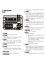
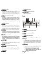
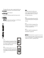
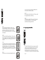
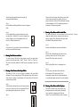
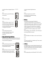
CK-105 USER MANUAL
I. PRODUCT DESCRIPTIONS
Thank you for using our company the CK-105. To optimize the performance of
this product, please read these operating instructions carefully to familiarize
yourself with the basic operations of this unit. The CK-105 is a unique DMX, 16
channel, dimmer board. This unit also comes with a memory back up battery to
save and retain your data. This unit has been tested at the factory before being
shipped to you, there is no assembly required. It features include:
� 16 channel DMX dimming console
� Easy Programmability
� 16 Built-In Programs
� 16 User Programs
� MIDI In, Out, and Thru
� US ITT DMX-512 protocol with 3-pin XLR
� Audio, Fade, and Speed Controls
� 16 channel fade and flash button controls
� Master fader control
� Digital LCD display screen
� Sound active via built-in microphone or Line In
� Mix chases
� Dark & Black Out buttons, Tap Sync button
� Polarity switch to accommodate different types of cable requirements
� Rear on/off switch
� 19” rack mount, 5 space
Read the instruction in this manual carefully and throughly, as they give important
information regarding safety during use and maintenance. Please keep this manual
with the unit, in order to consult it in the future.
WARNINGS
II
II.WARNINGS
1. To prevent or reduce the risk of electrical shock or fire, do not expose this unit
to rain or moisture.
2. Clearing memory often may cause damage to the memory chip, be careful not
to initialize your unit frequency often to avoid this risk.
3. Only use the recommended AC/DC power adaptor.
4.
5.
6.
7.
8.
9.
10.
11.
12.
13.
14.
15.
Be sure to save the packing carton in case you may ever have to return the unit
for service.
Do not spill other liquids or water in to or on to your amplifier.
Be sure that the local power outlet match that or the required voltage for your
amplifier.
Do not attempt to operate this unit if the power cord has been frayed or broken.
Please route your power cord out of the way of foot traffic.
Do not attempt to remove or break off the ground prong from the electrical
cord. This prong is used to reduce the risk of electrical shock and fire in case
of an internal short.
Disconnect from main power before making any type of connection.
Do not remove the top cover under any conditions. There are no user
serviceable parts inside.
Disconnect the unit’s main power when left unused for long periods of time.
This unit is not intended for home use.
Carefully inspect this unit for damage that may have incurred during shipping.
If the unit appears to be damaged, do not attempt any operation, please contact
your dealer.
This unit should be operated by adults only, never allow small children tamper
or play with this unit.
Never operate this unit under the following conditions:
- In places subject to excessive humidity
- In places subject to excessive vibration or bumps
- In area with a temperature over 450C/1130 F or less than 20C/35.60 F
III. CAUTIONS
1. There are no user serviceable parts inside this unit.
2. Do not attempt any repairs yourself, doing so will void your manufactures
warranty.
3. In the unlikely event your unit may require service please contact your nearest
dealer.
CONTROLS AND FUNCTIONS
IV
IV.CONTROLS
Front Panel:
8.
24 20 21 22 23
1
1
2
2
3
4
5
6
7
8
9
10
11
12
13
14
15
16
10
10
10
10
8
8
8
8
6
6
6
6
4
4
4
4
2
2
2
0
0
0
0
SPEED
FLASH
3
1
2
3
4
5
6
7
8
9
10
11
12
13
14
15
4
16
FADE
TIME
MIDI Signal
Manual Lock
PATTERNS
6
7
1
2
3
4
5
6
7
8
ADD1
9
10
11
12
13
14
15
16
ADD2
1
2
3
4
5
6
7
8
ADD3
2.
3.
4.
5.
6.
7.
Stand By
SRC-178
16CH Dimmer Console
4 Way
8 Way
12 Way
Built-in Patterns
16 Way
READY
FOG MACHINE
Glide
Tap Sync
Program
Step
Go
Dark
Manual
Audio
9
10
11
12
14
13
10.
Full on Black out
Lock Option
8
1.
MASTER
KILL
Program Lock
5
9.
2
AUDIO
25
15 16 17 18 19
Channel LED
LED’’s –
These 16 LED’s display the curent intensity of each channel.
Channel Sliders –
These 16 serve two functions: 1) They function as channel dimmers. 2) They
activate the programmed assigned to it’s respective channel.
Flash Buttons –
These 16 buttons serve two functions: 1) In program mode these buttons are
used to record it’s respective channel into a program. 2) In manual mode these
button are used to turn on a channel to full intensity..
Pattern LED –
These 16 LEDs indicate channel activity for their respective channel buttons.
Pattern Button –
The 16 pattern buttons activate the user programmed scenes or chase patterns.
You may program a static scene or a chase into each one of these 16 pattern
banks.
Built-in Pattern LEDs –
These green LEDs indicate activity of the respective pattern button.
Built-in Pattern Buttons –
11.
12.
13.
14.
These button activate the built in program associated with any of the eight
program buttons.
Add Button –
These three add buttons are used to activate the “ADD” function for any of the
pattern buttons located in the same row. For example, button “ADD 1” is used
in conjunction with pattern buttons 1-8, button “ADD 2” is used in conjunction
with pattern buttons 9-16, button “ADD 3” is used in conjunction with built-in
pattern buttons 1-8, “ADD” function activity will be indicated by a red LED
located directly above each add button.
LCD Display –
This high quality 3-digit LCD display is viewable from a variety of
comfortable angles. This display will indicate all the current relative controller
activity i.e., values for dimmer and chase speed, MIDI receive value, stand-by
mode, ect..
Glide Button –
This button will activate the glide (fade) function for a running chase pattern.
Tapping this button will activate and deactivate the Glide Function.
Program Button –
This button is used to activate program mode.
Go Button –
This button will serve three functions:
- When used in conjunction with the fade, this button will lock the
slider fade level.
- This button can also be used to lock the light intensity levels. When
you do not want the intensity levels changes in a scene or chase
pattern, pressing this button will lock your setting.
- When held down for more than one second this button will bypass
the Fade Time setting.
Tapping the Blackout button will exit the GO function.
Go Button –
This function will provide real time operation of the channel slider levels,
allowing you individual control over every channel slider. This function can be
combined with other function. A green LED above the manual button will
indicate manual operation. To exit the Manual Function tap either the Manual
or Blackout Buttons..
Audio Button –
This button will activate audio mode, which will sync a chase operation with
the beat of an audio source..
15. Tap Sync Button –
This button is used to manually establish a chase rate. The chase rate will
synchronize to rate you tap on the Tap Sync Button, tap the button twice a
second and the chase will advance two steps every second. Setting the Tap
Sync will override any previous chase rate settings..
16. Step Button –
This button gives you manual control over any running chase. Pressing this
button will advance the chase pattern one step. This function will work in
conjunction with the audio and tap sync functions, so be sure to lower the
audio sensitivity and turn off the tap sync function to have full control over the
chase patterns. This will also activate the lock function when combined with
the BLACKOUT BUTTON..
17. Dark Button –
This button provides a temporary black out function. When you hold down this
button all channel output will cease, until the button is released. Please note
that any chase running will continue to run in the back ground, so a chase may
not be at the same step as it was wheb the DARK button was initially pressed..
18. Full On Button –
Holding this button down will momentarily bring all 16 channels to full output.
This function will only work as long as the button is held down. This function
will function under any operating mode..
19. Blackout Button –
This button functions as a blackout and is also used to clear any current
operating mode. Holding this button down for over a second will bypass the
fade function. This will also activate the lock function when combined with
the STEP BUTTON..
20. Audio Level Slider –
This button controls the amount of audio sensitivity a chase will react to when
the “Audio” function is selected..
21. Speed Slider –
This slider controls the speed a chase will advance from step to step..
22. Fade Time Slider –
This slider adjust the initial fade time for the different operating modes. Fade
time will increase as the slider is position from 10 to 0, 0 giving the maximum
possible fade time..
23. Master Slider –
This slider controls total output..
24. Kill Button –
This button kills program mode or manual mode..
25. Fog Machine Button –
The button conterols fog machine..
Rear Panel:
26 27 28
POWER
DC INPUT
�
ON
MIDI
DM X OUT
�
�
�
OFF
1= Ground
2= Data 3= DATA+
33
34
TH RU
OUT
IN
AUDIO
REMOTE
FOG M ACHINE
1/4"stereo jack
0.1V~ 1Vp-p
DMX POLARITY SELECT
29
31
1= Ground
2= Data +
3= DATA-
�
DC 12V~ 20V,
500mA min.
30
LINE INPUT
MADE IN CHINA
Full on
Black out
GND
32
26. MIDI THRU –
Transmit MIDI data received on the MIDI IN connector..
27. MIDI OUT –
This connector is to receive incoming MIDI data..
28. MIDI IN –
This connector is used to send MIDI data..
29. DMX OUT –
This connector is used to send the DMX output data to a DMX dimmer pack..
30. Music Input –
This connector is used to receive an external music source. This source can
then be used to trigger the chase patterns. Without an incoming music source
connect to this unit, the unit will automatically use the internal microphone to
receive..
31. Remote Control –
This connector allows you to connect a remote foot control switch. This foot
switch give you control over two key functions, Full On and Stand By..
- Full On will bring the out of all slider channels to full intensity.
- Stand By will discontinue output to all 16 slider channels. This
function can be overrided by the Full On function.
32. Fog Machine Remote –
This connector allows you to connect our company fog machine to your
controller, allow you quick and easy access to fog machine basic operations..
33. Power Switch –
This switch control the units main power..
34. DC Power Input –
Plug in your DC 12V/500mA power supply to this jack to power your unit..
Step 3:
Select the fader channels to be included in your new
program by tapping on the channels Flash Button. If you
want several channels included in a step, you must press
all the channels at the same time.
OPERATION
V.OPERATION
� Programming
Quick Start:Note this quick start setup will only give you full fade output,
however the master output level may still be adjusted.
Step 4:
When you release the Flash Buttons all the channel LED’s
will flash briefly indicating that step has been programmed
into memory.
Step 5:
Repeat steps 3 and 4 until you have programmed all your
desired step for your new program. You may program up
to 100 steps per a program pattern chase.
1 2 3 4 5 6 7 8 9 10 1 12 13 14 15 16
3 4 53 5
10
10 10
10
8
88
8
6
66
6
4
44
4
2
22
2
0
00
Step 6:
When you have completed your programming press the
Blackout Button to exit program mode.
0
AUDIO SPED FADE MASTER
LFA S H
TIME
1 2 3 4 5 6 7 8 9 10 1 12 13 14 15 16 KIL
ProgramLock MIDSignal
2
ManualLock StandBy
1
APT T E R N S
1 2 3 4 5 6 7 8 AD1
9 10 1 12 13 14 15 16 AD2
SRC-178
16CH Dim er Console
Quick Start:Note this function allows you to program static scenes or chase
patterns with varying light level intensities. These programs may be stored into
any of the 16 user Pattern Buttons. This programming procedure may also be
combined with the “Quick Start” programming instructions.
READY Glide Program Go Manual Audio
6
1 2 3 4 5 6 7 8 AD3 FOGMACHINE TapSync Step Dark Fulon Blackout
4Way 8Way 12Way 16Way
Built-niPat erns
LockOption
Step 1:
Press the Program Button until it’s red indicator LED lights
up. Please note: If the program LED indicator does not light
up, the controller is in Lock Mode. To unlock the controller
piease see “Lock Function” in this manual.
Program
Step 1
Step 2:
Select a pattern bank (Program Buttons 1-16) you wish to
store your program to. Press the Pattern Button and its LED
will begin flashing slowly indicating program ode has been
activated.
Step 2
a scene or chase step, press the Program Button to lock
this scene into the controllers memory.
1 2 3 4 5 6 7 8 9 10 1 12 13 14 15 16
10 10
10
8
88
8
6
66
6
4
44
4
2
22
2
0
00
0
Step 5:
Repeat steps three and four until you rh a 100 steps or until
have programmed all your desired step.
AUDIO SPED FADEMASTER
TIME
F L A S H
53
10
1 2 3 4 5 6 7 8 9 10 1 12 13 14 15 16 KIL
Step 6:
When you have completed all your steps for this program
press the Blackout Button to exit this function and
automatically end the program function.
ProgramLock MIDSignal
2
ManualLock StandBy
14
P A T T E R N S
1 2 3 4 5 6 7 8 AD1
9 10 1 12 13 14 15 16 AD2
SRC-178
16CH Dim er Console
READY Glide Program Go Manual Audio
6
1 2 3 4 5 6 7 8 AD3 FOGMACHINE TapSync Step Dark Fulon Blackout
4Way 8Way 12Way 16Way
Built-nPaterns
LockOption
Step 1:
Press the Program Manual Buttons until there green
indicator LEDs light up. Please note: If the program LED
indicator does not light up, the controller is in Lock
Mode. To unlock the controller please see “Lock Function”
in this manual.
�
Program
1 2 3 4 5 6 7 8 9 10 1 12 13 14 15 16
Step 1
2
10
10 10
10
8
88
8
6
66
6
4
44
4
2
22
2
0
00
0
1 2 3 4 5 6 7 8 9 10 1 12 13 14 15 16 KIL
ProgramLock MIDSignal
ManualLock StandBy
1
P A T T E R N S
1 2 3 4 5 6 7 8 AD1
S te p 2
9 10 1 12 13 14 15 16 AD2
Step 4:
After you have set all your desired channel fader level, for
AUDIO SPED FADEMASTER
TIME
F L A S H
Step 2:
Select a pattern bank (Program Buttons 1-16) you wish to
store your program to. Press the Pattern Button and its LED
will begin flashing slowiy indicating program ode has been
activated.
Step 3:
Use the slider to adjust your desired channel intensity. The
channels intensity will vary depending on the position of the
slider. When the slider is set to zero (0) there will be no
channel activity will be at it’s maximum. The LCD display
will also detail the channel fader level in increments of zero
to 100.
Programming with Audio Effect
10
10
8
8
6
6
4
4
2
2
0
0
S te p 4
SRC-178
3
16CH Dim er Console
READY Glide Program Go Manual Audio
1 2 3 4 5 6 7 8 AD3 FOGMACHINE TapSync Step Dark Fulon Blackout
4Way 8Way 12Way 16Way
Built-niPat erns
LockOption
The audio effect function allows you to program specified
channels to an internal audio bank. Only one scene can be
programmed using the Audio Effect and can only be
activated by an audio source. This function will only work
if “Audio Mode” is activated while a chase pattern is running.
Step 1:
Program
Step 5
Turn off any chase patterns that may be running, by
pressing the Blackout Button.
Once you have selected you chase patterns use the speed
slider to control amount of time it takes the chase to
progress from scene to the next. This adjustment can range
from the minimum of 1/10 of a second progression to a
maximum of 10 minutes progression.
Step 2:
Press the Manual and Program Buttons to enter the program
mode.
�
Step 3:
Use the channel sliders to select the channels you want
activated by the “Audio Effect”. Be sure the channels you
wish to program are set to their maximum levels and
the rest set to threr minimum level.
Running a Chase Pattern with the Audio Slider
This mode will allow to run your patterns to the beat of music. You may
change the Audio Sensitivity at any time while the chase
pattern is running. Your adjustments to the speed slider
will affect the chase pattern in real time.
Audio
Step 4:
Once you have set your channels, tap the Audio Button to
set this scene into the bufer memory.
�
�
Step 1:
Press the Audio Button to activate the Audio Mode.
Step 3
Step 2:
Press the Chase Pattern Button that stores the chase
pattern you wish to activate. The chase pattern
button’s LED will you wish to activated.
Running Chase Patterns and Scenes
You may run any of the built in chase patterns or one of your preset chase
patterns in four different modes “Audio”, “Speed”, “Glide”, or “Tap Sync”.
The next section of the manual will detail the proper operation of these four
modes.
Step 3:
Move the Speed Slider level to its minimum level..
Step 4:
You may now use the audio silder to adjust the
music sensitivity. The music sensitivity will
automatically control either the internal microphone
or an audio input signal connect to the rear of controller.
Running a Chase Pattern with the Speed Slider
This mode will allow to run your patterns according to the speed slider
adjustment. You may change the speed Slider adjustment at any time while the
chase pattern is running. Your adjustments to the speed slider will affect the
chase pattern in real time.
Step 1:
Select the pattern button(s) that stores the chase patterns or
scene you wish to activate. The select patterns LEDs will
glow indicating that pattern has been activated.
�
Step 1
Step 2:
10
10
8
8
6
6
4
4
2
2
Running a Chase Pattern with the Tap Sync
This mode will allow to run your patterns to your
determined speed rate. In this mode you manually
enter a speed rate by tapping on the Tap Sync
Button. You can use this function to create a constant
rate to the beat of the music by tapping the Tap Sync to
the beat.
it and reselect it in order for the glide function to be
activated.
Step 1:
Be sure the Audio, Speed, and Fade Time Sliders are
set to lowest levels.
Step 3:
To discontinue the glide effect, deselect the Glide
Button and deselect the Chase Pattern that is running,
or press the Blackout Button.
Step 2:
Select your desire chase patterns.
Step 2
�
Step 3:
Tap the Tap Sync Button at a regular rate. You will
notice that the chase pattern will begin to advance at
the same rate you were tapping. You will also notice
that the Tap Sync LED will flash at the same rate you
were tapping on the Tap Sync Button.
Tap Sync
Step 3
Step 4:
You can override this setting at any time by
selecting the “Audio Function”. You may also clear
this setting by raising the Speed Slider to it’s
maximum level.
�
Step 2:
Press the Flash Buttons for the channels you wish to remove from the chase
pattern.
Running a Chase Pattern Using the Glide Function
This mode will allow to run your patterns to a preset fade time. This gives the
effect of one scene fading in to the next. This function is used in conjunction
with any of the other three operating modes.
Step 1:
While in any of the other operating modes, press the Glide
Button. The Glide LED will begin to glow indicating
the glide function has been activated.
Step 2:
With the glide function activated press the Chase Pattern
Button that stores the chase you wish to run in glide
mode. If the chase is already running you must deselect
Step 3:
The channels you selected will now discontinue output. To return to normal
operation, tap the Kill Buonce again.
�
Step 1
Kill Function
This function allows you to remove specific channels from a chase or scene.
You may take out as many channels from a scene or chase patterns as you
would like. Please note, After you remove a channel from a chase or scene, the
channel’s fader level LED will continue to remain lit for a scene, or continue
to flash for a chase pattern. This is normal and serves as a reminder that
channel is programmed into your scene or chase . Be sure thst although the
channel LED is on the channel is not producing any output. To add a Kill:
Step 1:
Press the Kill Button to activate the Kill Mode, a yellow LED will begin to
glow indicating Kill Mode has been activated.
Add Function
This function allows you to turn on more than one chase pattern on the same
bank. Without this function you may turn on more than one chase pattern as
long as they are in different banks. In order to run more than one chase pattern
from the same bank you must activate the Add Function:
Step 1:
From any operating mode press the Add Button (ADD 1, ADD 2, or ADD 3),
Step 2
from the that corresponds to a chase pattern bank that stores the chase pattern
you wish to activate.
While holding down the pattern button described in step 2, turn on the units
main power. Pattern buttin LEDs 1,2,3, and 4 will begin to flash and “SET”
will appear in the LCD disoplay indicating that you have entered the MIDI
set-up menu.
Step 2:
Once you have pressed the ADD Button that correspond with chase pattern
you wish to activate you will notice the ADD Button’s red LED will begin to
glow indicating you may now make a chase pattern selection. At this point
make your selection.
Step 4:
While Pattern Button 1,2,3, and 4 are flashing you can press 1 to change the
IN channel and 2 to change the OUT channel.
Step 3:
To discontinue an individual chase be sure the ADD Button is activate and
deselect the chase pattern you wish to deactivate. You may also press the
Blackout Button to discontinue all chase functions.
Step 5:
To change the channel press either Pattern Buttons 1 or 2 depending on with
you would like to change (see step 4).
Step 6:
Once you have pressed the Pattern Button that corresponds with setting you
wish change you will notice that a Channel LED comeson, this indicates the
current value, Channel 1 LED for Address 1, Channel 2 LED for Address 2,
Channel 3 LED for Address 3 and so on. To change the setting press the Flash
Button that corresponds with the address you wish to apply. Obviously,
address can only be set from 1-16. Once you have made your changes press
the Blackout Button to record your setting.
For example: If you are running chase pattern 1 and wish to activate chase
pattern 2 and run it at same the time, you must first press the ADD 1 Button.
This will then allow you to activate chase pattern 2.
�
Operating Under General MIDI
This mode will allow to control your controller through a MIDI sequencer or
MIDI controller such as keyboard or durm machine.
Setting In and Out MIDI Channels:
In order to run your controller from a MIDI device you must set the In and Out
MIDI channels, much the same as a DMX dimmer pack and DMX controller
have to be set to the same DMX address to communicate with each other. This
next section will describe how to set and change the MIDI setting.
Step 1:
Turn off the mainpower to the unit.
Step 2:
With the main power disconnected press and hold down Built-in Pattern
Buttons 5,6,7, and 8 all at the same time.
Step 3:
Step 7:
Once you have made your necessary changes press the Blackout Button to exit
this function and return to normal operations.
�
MIDI Conversion Translations
The following chart details the function per a MIDI note. The velocity a note is
struck will translate in to the light output intensity.
Note Number
Velocity
Function
22-37
Turns Patterns 1-16 On & Off
38-45
Turns Built In Patterns 1-8 On & Off
46-61
Turns Fader Channel 1-16 On & Off
62-64
Turns the ADD Function On & Off
65
Channel Intensity
DARK
66
(Light Output)
FULL ON
67
Enables Manual Mode
68
69
70
71
�
Activates Glide Function
Turns Audio on Function On & Off
Advances a Scene in Mnual Mode
BLACKOUT
�
LCD Display Value Shift
This function changes the LCD values from percentage to DMX value. 0~100
will equal percentage and 000~255 will equal DMX value. To change the way
the LCD displays the value.
Step 1:
While the power is on press and hold down Pattern Buttons 3, 6, 10, and 15.
Step 2:
Wait approximately 30 seconds and turn the power back on. This will delete all
the chase patterns your programmed.
Step 1:
Shut down the main power and press and hold down built-in pattern buttons 5,
6, 7, and 8.
�
Step 2:
While holding down the pattern button, turn the main power back on. This will
enter the set-up mode.
Step 3:
You will notice that Pattern Button LEDs 1, 2, 3, and 4 have turn on. Press
Button 3 for percentage or 4 for DMX values.
Step 4:
When you have made your selection press the Blackout Button twice to lock
this setting in to memory and return to normal operation.
�
Remote Control
On the rear of the unit there is a connection for a remote control, this remote is
a wired foot switch. This remote has been designed with a band in mind. The
remote allows you hand-off control over two of the key function of the
controller Full On and Stand By (Blackout).
Full On: This function will bring all the slider channels to full output.
Stand By: This function will shut down all slider channel output. During stand
by mode the chase patterns will continue to run in the back ground. Full On
function will overried the controller when it is in stand by mode.
Initializing to Default Setting
This function will erase all your press programs and scenes. The built-in chase
patterns will not be effectd. Caution! This function is irreversible and the
chase patterns can not be recovered once the memory is erased. To erase the
controller memory:
Locking the Controller
Program Lock: This function allows you to lock the controller’s program
function, preventing someone from changing or erasing valuable programs.
To lock the controller program settings:.
Step 1:
Press and hold down the Step and Blackout Buttons simultaneously. You will
notice the lock icon flashing on the left side of the LCD display, this indicates
the lock function may be set.
Step 2:
While holding down the Step and Blackout Buttons, use the Program Button to
toggle between “ON” and “OFF” in the LCD display. Make your selection and
release the Program Button.
Step 3:
After you have made your changes release the Step and Blackout Buttons to
return to normal operation.
Manual Lock: This function allows you to lock the controller memory,
preventing someone from changing or erasing valuable programs. To lock the
controller:.
Step 1:
Press and hold down the Step and Blackout Buttons simultaneously. You will
notice the lock icon flashing on the left side of the LCD display, this indicates
the lock function may be set.
Step 2:
While holding down the Step and Blackout Buttons, use the Program Button to
toggle between “ON” and “OFF” in the LCD display. Make your selection and
release the Program Button.
Step 3:
After you have made your changes release the Step and Blackout Buttons to
return to normal operation.
TECHNICAL SPECIFICATIONS
VI
VI.TECHNICAL
Power Input ………………………………
………………………………DC 12~20V 500mA Min.
Internal Fuse ……………………………………
……………………………………F1A 250V 5x20mm
DMX Out ………………………………………
………………………………………male XLR socket x 1
MIDI IN/OUT/THRU …………………………
…………………………5 pin multiple socket
....……
……
....……
……
.. 482x22x62mm
Dimensions ……………………………
……………………………..
……..
……..
Weight …………………………………………………………
…………………………………………………………4.4 Kgs
www.cklight.com.cn