1
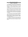
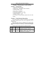
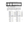
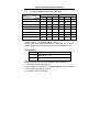
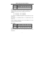
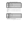
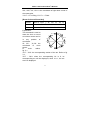
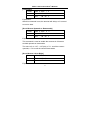
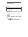
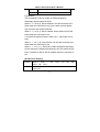
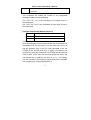
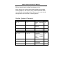
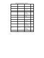
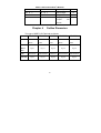
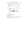
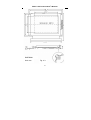
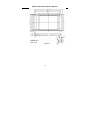
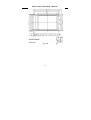
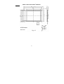
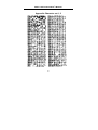
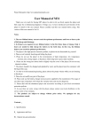
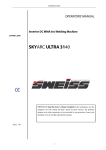
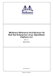
SPRT LCD Terminal
User’s Manual
Beijing Spirit Technology
Development Co.,Ltd.
www.sprinter.com.cn
Content
Chapter 1 Introduction ............................................................... 1
Chapter 2 Performance and Interface....................................... 2
Section 1 Specification .................................................... 2
Section 2 Serial Interface Description ............................. 2
Section 3 DIP Switch Setting........................................... 3
Chapter 3 Command Format..................................................... 5
Section 1 Command Description........................................ 5
Section 2 Command List Table...................................... 18
Chapter 4 Outline Dimension .................................................. 20
Chapter 5 Contrast, Brightness Adjustment Method............. 28
Section 1 Contrast ..................................................... 28
Section 2 Brightness.................................................. 28
Chapter 7 Safety Precautions............................................. 29
Appendix Character Set I, II.................................................. 30
SPRT LCD Terminal User’s Manual
Chapter 1 Introduction
LCD terminal as the crystallization of the contemporary
high-tech products, which has not only ultra-thin flat, color
fidelity, but also small size, power consumption provinces, long
life, non-ray, earthquake, explosion-proof, and many other
advantages, is the ideal replacement display for industrial
instrumentation, electrical and mechanical equipment and other
industries.
The LCD terminal is very easy to use, you only need to
send the character or Chinese characters through the serial
interface to the terminal, then the character or Chinese
characters will be shown on the terminal in accordance with the
size, direction, location that had been set. It is very convenient
to draw dots, straight lines, rectangles, circles and arcs, and so
on. From top to bottom, from left to right to screen displaying
function allows you show continuous curve more speedily and
conveniently.
The terminal can not only show all ASCII characters,
German, French, Russian, Japanese Katakana, mathematical
symbols, special symbols, also can show the GB Library I, II
Chinese characters. The terminal also provide a variety of
functions to modify the characters: such as rotating, zooming,
and character spacing, line spacing adjustment, scintillation,
negative direction and so on.
In addition, the terminal also has the function that shows
the preset graphics. You simply write the prepared BMP image
files into E2ROM of the terminal for preservation. When need to
demonstrate, the user just need to use the graphic command to
display it.
1
SPRT LCD Terminal User’s Manual
Chapter 2 Performance and Interface
Section 1
Specification
1. Display dot: 320×240 pixels
2. Display color:Monochrome (blue and white)
3. Working Voltage:DC5V
4. Max. Power:5V×950mA
5. Operating Temperature:0~50℃
6. Saving Temperature:-20℃~60℃
7. Relative humidity:<60%
All of the type of terminal exterior, please refer to the forth
chapter.
Section 2
Serial Interface Description
The serial interface of SPRT LCD Terminal is 5-pin single
row socket, through the W5、W6、W7 to select the TTL or
RS232C level.
When W5, W6, W7 are 1,2 shorted at TTL level and 2,3
shorted at RS232C Level (W5, W6, W7 both have white spots
one end of 1). When it is ex-factory, it should select RS232C
level.
All-pin serial interface signals are defined as follows:
Description
Pin Signal Direction
This signal is the “SPACE” status, which
1
DSR
Output
means the terminal is “ On-line”
When use the X-0N/X-OFF protocol,the
2
TXD
Input
terminal sends the control code
(X-0N/X-OFF) to the host
2
SPRT LCD Terminal User’s Manual
3
RXD
Input
4
CTS
Output
5
GND
Section 3
The terminal receives data from the host
When this signal shows the “MARK”, the
terminal is busy and can’t receive data;
when it shows the “SPACE”, the terminal
is ready and can receive data
Signal ground
DIP Switch Setting
The baud rate for the terminal can be set by the DIP switch
on the main circuit board, there are different baud rates:
300,600,1200,2400,4800,9600,19200 and 38400. You can set
the baud rate according to the following table. The white spot
means K1. The default baud rate is 9600B.P.S when it is exfactory.
3
SPRT LCD Terminal User’s Manual
Serial interface communication format:
Start bit
Data bit
Parity bit
Stop bit
1
7/8
1
1
Both of the start and the stop bit are 1 bit. The data bit is 7
bit or 8 bit. Odd or even bit is 1 bit. When you select 7 bit data,
only permit even parity. The ways of checking can be selected
by K4 and K5 on the DIP switch, that you can refer to the table
2-3. The default is no parity when it is ex-factory, namely K4,
K5=ON.
For serial interface, the RS-232 signal as follows:
MARK=Logic“1”(from EIA-3V to -27V low level)
SPACE=Logic“0”(from EIA+3V to +27V high level)
There are two handshaking ways to choose from, one way is
mark control, the other way is the X-ON/X-OFF protocol. Please
refer to the chart 2-4 for the description of the two handshaking
ways.
Data direction
RS-232C signal
Handshaking
Enter allowed
Signal “4”shows “Space”
Mark control
Signal “4”shows “Mark”
Enter permitted
X-ON/
Enter allowed
Send X-ON code “11H”
X-OFF control
on the signal “3”
Enter permitted
Send X-OFF code “13H”
on the signal “3”
Table 2-3 Two Handshaking Ways
Please according to the following instructions to operate
the serial interface:
(1)Use the DIP switch K1, K3 to select the baud rate;
(2)Use the DIP switch K4, K5 to select odd or even;
4
SPRT LCD Terminal User’s Manual
(3)Use the W5、W6、W7 to select interface level;
(4)When the terminal is busy, the signal line CTS (signal “4”)
will be set to “busy” by the terminal, and shows “Mark”.
Otherwise it is ready to receive data, and shows “SPACE”:
(5)Under the control of X-ON/X-OF, in “busy” status, the
terminal will send X-OFF (13H) code; in “ready” status, send
X-ON(11H)code;
(6)Under the control of mark, the host will send or stop
sending code string to the terminal according to the status
“ready” or “busy”.
Chapter 3
Section 1
Command Format
Command details
User can use the switch W8 on the control board to set the
initial status of the terminal when it powers on. When W8 set to
1, 2 short circuit ( the white spot means “1”), there is graphics
showed on the screen if the graphics had been downloaded
in. When W8 set to 2, 3 short circuit, there is no graphics.
[Select Character Set]
Format
ASCⅡ: ESC n
Decimal: 27
n
Hex:
n
1B
Explanation: the value of n is31H~33H, the corresponding
character set is 1, 2, 3. When the user wants to display
character or Chinese character, he can select the
corresponding character set by using this command, then
5
SPRT LCD Terminal User’s Manual
send the codes for the characters. The default setting is
Character Set 3.
[Set Character Spacing]
Format
ASCⅡ: ESC Z
n
Decimal: 27
90 n
Hex:
5A n
1B
Explanation:
This command is used to set the character spacing.
The value of n is 0~255, when the terminal is powered on or
initialized, the character spacing is set to 0.
[Set Line Spacing]
Format
ASCⅡ: ESC H
n
Decimal: 27
72 n
Hex:
48
1B
n
Explanation:
This command is used to set the line spacing.
The value of n is 0~255, when the terminal is powered on or
initialized, the character spacing is set to 0.
[Clear Screen]
Format
ASCⅡ: ESC
Q n
Decimal: 27
81 n
Hex:
51 n
1B
6
SPRT LCD Terminal User’s Manual
Explanation:
When n=0, the terminal clears all the data on the screen, then
the system coordinate returns to (0, 0);
When n=1, the terminal only clears the negative data on the
screen, the system coordinate doesn’t change.
When n=2, the terminal only clears the twinkling data on the
screen, the system coordinate doesn’t change.
[Carriage Return]
Format
ASCⅡ:CR
Decimal:13
Hex:
0D
Explanation:
This command is used to move the system coordinate to the left
side. It means Y coordinate plus the height of character and line
spacing, X coordinate changes to 0.
[Horizontal, Vertical Enlarging and Rotation Setting]
Format
ASCⅡ : ESC f
n
Decimal: 27 102 n
Hex:
1B
66
n
Explanation:
This command is used to enlarge the character horizontally or
vertically, and set the rotation angle of the character.
n.7, n.6, n.5: set the multiple of horizontal enlarging;
7
SPRT LCD Terminal User’s Manual
n.4, n.3, n.2: set the multiple of vertical enlarging;
n.1, n.0: set the rotation angle of the character.
Value
Multiple
n
Horizontal
Vertical
7
6
5
4
3
2
0
0
0
0
0
0
0
1
0
0
1
0
0
1
2
0
1
0
0
1
0
3
0
1
1
0
1
1
4
1
0
0
1
0
0
5
1
0
1
1
0
1
6
1
1
0
1
1
0
7
1
1
1
1
1
1
n.1, n.0=00(no rotation), 01(reverse rotation 90℃), 10(reverse
rotation 180℃), 11(reverse rotation 270℃).
Notice: The 8×16 ASCII characters in Character Set 3 can be
rotated. When the terminal is powered on or initialized, n is 0.
[Initialization]
Format
ASCⅡ : ESC @
Decimal: 27 64
Hex:
1B
40
Explanation:
After this command is set, the following items should be:
1. Character and line spacing is 0;
2. The multiple of horizontal or vertical enlarging is 0, no rotation;
3. The system coordinate is (0, 0);
4. Character set 3 is selected.
8
SPRT LCD Terminal User’s Manual
[Set System Coordinate]
Format
ASCⅡ : ESC z XL
XH
Decimal: 27 122 XL XH
Hex:
1B
7A XL
XH
YL YH
YL
YH
YL YH
Explanation:
This command is used to set the system coordinate, mainly
used for defining the position to display characters and
graphics.
XL: “X” low 8 bit XH: “X” high 8 bit
YL: “Y” low 8 bit YH: “Y” high 8 bit
The range of x coordinate value is 0~(horizontal dots of the
screen -1)
The range of y coordinate value is 0~(vertical dots of the
screen -1)
If the X system coordinate is set to the multiple of 8, it can
improve the displaying speed.
[Draw Dot]
Format
ASCⅡ : ESC d XL
XH
Decimal: 27 100 XL XH
Hex:
1B
64 XL
XH
YL YH
YL
YH
YL YH
Explanation:
After this command is set, user can draw dots at any position on
the screen.
9
SPRT LCD Terminal User’s Manual
[Draw Curve]
Format
ASC Ⅱ : ESC x
X2H Y2L Y2H
X1L
X1H
Y1L
Y1H
X2L
Decimal: 27 120
X2H Y2L Y2H
X1L
X1H
Y1L
Y1H
X2L
Y1H
X2L
X2H
Hex: 1B 78
Y2L Y2H
X1L
X1H
Y1L
Explanation:
After this command is set, user can draw curve in any direction
and length.
X1L, X1H, Y1L, Y1H: is the jumping-off coordinate of the curve
drawn.
X2L, X2H, Y2L, Y2H: is the end point coordinate of the curve
drawn.
[Draw Rectangle]
Format
ASCⅡ : ESC j
X2H Y2L Y2H
Decimal: 27 106
X2H Y2L Y2H
Hex: 1B 6A
Y2L Y2H
X1L
X1L
X1L
X1H
X1H
Y1L
Y1H
X2L
X1H
Y1L
Y1H
X2L
Y1H
X2L
X2H
Y1L
Explanation:
This command is used to draw rectangle.
X1L, X1H, Y1L, Y1H: is the coordinate of left upper corner of
10
SPRT LCD Terminal User’s Manual
the rectangular;
X2L, X2H, Y2L, Y2H: is the coordinate of right down corner of
the rectangular.
Y1H.7 = 0: no filling; Y1H.7 = 1: Filled.
[Draw Circle and Round Arc]
Format
ASCⅡ : ESC y XL
XH
Decimal: 27 121 XL XH
Hex:
1B
79
YL YH R
YL
XL XH YL
YH R
YH R
Explanation:
This command is used to
YH.1
YH.2
draw the circle or round
arc whose centre can be
YH.0
YH.3
in any position of
coordinate.
XL, XH , ,YL,YH: the
YH.7
YH.4
coordinate
of
circle
centre;
YH.6
YH5
R:
circle
radius;
fig. 3.1
YH.7~YH.0: the corresponding section of the arc. Refer to fig
3.1;
YH.7 ~ YH.0: when the corresponding bit is 0, its
corresponding arc will be displayed; when it is 1, the arc
won’t be displayed.
11
SPRT LCD Terminal User’s Manual
[Time-lapse]
Format
ASCⅡ : ESC l n
Decimal: 27 108 n
Hex:
1B
6C
n
Explanation:
After this command is set, the terminal will delay n×0.1 second
to receive data.
[Scroll Screen Upwards or Downwards]
Format
ASCⅡ : ESC h n
Decimal: 27 104 n
Hex:
1B
68 n
Explanation:
This command is used to enable the contents in full-screen
scrolled upwards or downwards.
The value of n is -127~+127(dot), n.7=1: scroll the content
upwards; n.7=0: scroll the content downwards.
[Scroll Screen Left or Right]
Format
ASCⅡ : ESC c n
Decimal: 27 99 n
Hex:
1B
63 n
Explanation:
12
SPRT LCD Terminal User’s Manual
This command is used to enable the contents in full-screen
scrolled to the right or left side.
The value of n is -127~+127(dot), n.7=1: scroll the content
to left side; n.7=0: scroll the content to right side.
[Delete]
Format
ASCⅡ : ESC
X2H Y2L Y2H
s
X1L
X1H
Y1L
Y1H
X2L
Decimal: 27 115 X1L X1H Y1L Y1H X2L X2H
Y2L Y2H
Hex: 1B 73
Y2L Y2H
X1L
X1H
Y1L Y1H
X2L
X2H
Explanation:
This command is used to delete the content displayed in the
rectangle frame.
X1L, X1H, Y1L, Y1H: is the coordinate of left upper corner of
the rectangular;
X2L, X2H, Y2L, Y2H: is the coordinate of right down corner of
the rectangular.
This command is invalid when the content is displayed
flickeringly.
[Set Display Flickeringly]
Format
ASCⅡ : ESC S
13
n
SPRT LCD Terminal User’s Manual
Decimal: 27 83 n
Hex:
1B
53 n
Explanation:
This command is used to enable or disable displaying
flickeringly and the speed of flicker.
When n. 1, n.0: (0,0), flicker disabled. The data received won’t
flicker after this command is set, but the data received before
this command set will be still flicker.
When n. 1, n.0: (0,1), flicker enabled. All the data received will
flicker after this command is set.
n.2 control the speed of flicker. When n.2=1, fast; When n.2=0,
slow.
When n. 1, n.0: (1,0), cancel flicker. All the data received won’t
flicker after this command is set.
When n. 1, n.0: (1,1), delete the content displayed flickeringly.
All the data that is displayed flickeringly, also the data that has
been cancelled to flicker will be deleted after this command is
set.
[Set Reverse Display]
Format
ASCⅡ : ESC i
X2H Y2L Y2H
X1L
X1H
Y1L Y1H
X2L
Decimal: 27 105 X1L X1H Y1L Y1H X2L X2H
Y2L Y2H
14
SPRT LCD Terminal User’s Manual
Hex: 1B
Y2L Y2H
69 X1L
X1H
Y1L
Y1H
X2L
X2H
Explanation:
This command will enable the content in the designated
rectangular frame reverse displaying.
X1L, X1H, Y1L, Y1H: is the coordinate of left upper corner of
the rectangular;
X2L, X2H, Y2L, Y2H: is the coordinate of right down corner of
the rectangular.
[Transfer Downloaded Bitmap Graphics]
Format
ASCⅡ : ESC P n
Decimal: 27 80 n
Hex:
1B
50 n
Explanation:
All of the displayed content can be divided into a fixed part and
changeable part on the screen. For the fixed part, user can
edit the graphics firstly in the PC, then download it into the
E2ROM of the terminal and save it, when it is needed, just
transfer it by using this command. The E2ROM chip the terminal
used is 256k, it can save the data even power off. When the
user transfer the n graphics, the value of n is (1~63). Before
use this command, user needs to set the start point coordinate
of the graphics by using command ESC z.
15
SPRT LCD Terminal User’s Manual
[Move Coordinate Upwards or Downwards]
Format
ASCⅡ : ESC a n
Decimal: 27 97 n
Hex:
1B
61 n
Explanation:
This command will move upwards or downwards the coordinate
from the current position to the new position. “n” is the
movement distance, the range of the value is -127~+127 dot.
D7 is n’s symbol bit, when D7=1, move downwards; D7=0,
move upwards.
[Move Coordinate Left or Right]
Format
ASCⅡ : ESC b n
Decimal: 27 98 n
Hex:
1B
62 n
Explanation:
This command will move left or right the coordinate from the
current position to the new position. “n” is the movement
distance, the range of the value is -127~+127 dot. D7 is n’s
symbol bit, when D7=1, move right; D7=0, move left.
[Set Backlight]
Format
ASCⅡ : ESC B n
Decimal: 27 66 n
16
SPRT LCD Terminal User’s Manual
Hex:
1B
42 n
Explanation:
This command controls the backlight on or off. When n=1, turn
off the backlight; When n=2, turn on the backlight.
[Copy Full Screen]
Format
ASCⅡ : ESC k
n
Decimal: 27 107 n
Hex:
1B
6B n
Explanation:
User can use this command to copy the current full screen
graphics to the memory chip of the terminal. When need to
display the graphics, just use command 1B 4B n (Hex) to
transfer it. n is the serial number of the copied graphics, the
range of n value is 1~63.
[Display the Copied Full Screen]
Format
ASCⅡ : ESC K n
Decimal: 27 75 n
Hex:
1B
4B n
Explanation:
This command is used to transfer the copied full screen
graphics which is saved in the memory chip of the terminal. n is
the serial number of the copied graphics. As all the copied
17
SPRT LCD Terminal User’s Manual
graphics are full screen display, so before use this command,
the user should set the system coordinate to (0, 0).
Note: When there are both downloaded graphics and copied
screen graphics in the memory chip, as the commands which
use to transfer these graphics are different, so the user should
distinguish the serial number of these graphics.
Section 2 Index of Command
ASC Ⅱ
ESC n
Hex
1B
n
Description
Page
Select Character
5
Set
ESC Z
n
1B
5A
n
Set
Character
6
Spacing
ESC H n
1B
48
ESC Q
1B
51
CR
OD
ESC f
n
1B
66
n
n
Set Line Spacing
6
Clear Screen
6
Carriage Return
7
Horizontal,
7
Vertical Enlarging
and
Rotation
Setting
ESC @
ESC z
x y
1B
40
1B
7A
x y
Initialization
8
Set
9
System
Coordinate
ESC d
x y
1B
64
x y
18
Draw Dot
9
SPRT LCD Terminal User’s Manual
ESC
x
x1
y1
y2
ESC
x2 1B
78
x1
y1
x2 Draw Curve
10
6A
x1
y1
x2 Draw Rectangle
10
79
x y R
y2
j
x1
y1
y2
x2 1B
y2
ESC y
x y R
1B
Draw
Circle
or
11
Round Arc
ESC l
ESC h
n
n
1B
6C n
Time-lapse
1B
68
Scroll
n
12
Screen
Upwards
12
or
Downwards
ESC c
n
1B
63
n
Scroll Screen Left
12
or Right
ESC
s
x1
y1
y2
x2 1B
73
x1
53
n
y1
x2 Delete
13
y2
ESC S
n
1B
Set
Display
13
Flickeringly
ESC
i
x1
y2
ESC P
y1
x2 1B
69
x1
y1
y2
n
1B
x2 Set
Reverse
14
Display
50
n
Transfer
15
Downloaded
Bitmap Graphics
ESC a
n
1B
61
n
Move Coordinate
upwards
16
or
downwards
ESC b
n
1B
62
n
Move Coordinate
19
16
SPRT LCD Terminal User’s Manual
Left or Right
ESC
B
n
1B
42
n
Set Backlight
16
ESC
k n
1B
6B
n
Copy Full Screen
17
ESC
K
1B
4B
n
Display
the
17
Copied
Full
n
Screen
Chapter 4
Outline Dimension
The type of SPRT LCD Terminal as follows:
SP-4DSA
Structure
SP-4DSC
SP-5DSA
SP-5DSB
SP-5DSC
LCD+Control
LCD+Control
LCD+Control
LCD+Control
LCD+Control
Board
Board
Board
Board
Board
Control
Board
Fig 4.1
Fig.4.1
Fig.4.2
Fig.4.2
Fig.4.2
SPRT50081
SPRT320240B
SPRT50174
SPRT320240C
SPRT320240D
Fig 4.3
Fig 4.4
Fig 4.5
Fig 4.6
Fig 4.7
Size
LCD
LCD Size
20
SPRT LCD Terminal User’s Manual
Display Screen
Control Board
Fig. 4.1
Unit: mm
J1: Serial port ( 5-pin socket)
J2: Power supply port ( 4-pin socket)
SWK1: DIP switch
W8: Slip stitch, it is used to set whether there is graphics
showed when power on.
VR1: Potentiometers, it is used to adjust the display contrast
21
SPRT LCD Terminal User’s Manual
Display Screen
Control Board
Fig. 4.2
Unit: mm
J1: Serial port ( 5-pin socket)
J2: Power supply port ( 4-pin socket)
SWK1: DIP switch
W8: Slip stitch, it is used to set whether there is graphics
showed when power on.
VR1: Potentiometers, it is used to adjust the display contrast
22
SPRT LCD Terminal User’s Manual
DMF50081
Unit: mm
Fig. 4.3
23
SPRT LCD Terminal User’s Manual
SPRT320240B
Unit: mm
Fig. 4.4
24
SPRT LCD Terminal User’s Manual
DMF50174
Unit: mm
Fig. 4.5
25
SPRT LCD Terminal User’s Manual
SPRT320240C
Unit: mm
Fig. 4.6
26
SPRT LCD Terminal User’s Manual
SPRT320240
Unit: mm
Fig. 4.7
27
SPRT LCD Terminal User’s Manual
Chapter 5
Section 1
Contrast and Lightness Adjustment
Adjust Contrast
Method 1: When 2, 3 ports of W4 are short circuit, adjust the
VR1 to change the contrast.
Method 2: When 2, 3 ports of W4 and 1, 2 ports of W3 are short
circuit, can install a 20K adjustable resistance on the J4 socket
to adjust the contrast.
Method 3: When 2, 3 ports of W4 are short circuit, use J2-2 to
input terminal driving voltage, Vo=-10V~-22V,30mA.
Section 2
Adjust Lightness
When the terminal ex-factory, the default is 1, 2 ports of W3
and W1 are short circuit, the backlight power is provided by
J2-1(DC+5V), the lightness is can’t be adjusted.
Method 1: When 1, 2 ports of W2 are short circuit and W1 is
disconnected, can install a changeable resistance(about10W,
20Ω) on J3, thus user can adjust the lightness by adjusting the
changeable resistance.
Method 2: When 2, 3 ports are short circuit and W1 is
disconnected, can input a fixed DC power(such as DC+5V,
DC+9V, DC+12V, 1A) from J2-3 port, and install a changeable
resistance(about10W,20Ω) and a fixed resistance in series on
J3, thus user can adjust the lightness by adjusting the
changeable resistance.
Method 3: When 2, 3 ports are short circuit and W1 is
disconnected, can input a changeable DC power (voltage from
DC+3V to DC+7V, power about 10W), user can adjust the
28
SPRT LCD Terminal User’s Manual
lightness by adjusting the voltage.
Note1: The terminal only can use DC+5V adaptor, the
current consumed by the control circuit is about 200mA, most
of the current is consumed by the backlight lamp. If user wants
to supply power to the backlight lamp separately or wants to
control the on or off of the backlight, then can choose Method 3
to adjust.
Note 2: If the brightness of the backlight is too high, it would
shorten the using time of the backlight lamp; also increase the
power of the adaptor, so user should pay attention to avoid the
brightness is too high.
Chapter 7
Security Instruction
To avoid incorrect operation or disposal, please notice
these items as follows:
△Before you clean the display screen of the terminal,
please close the terminal and computer firstly;
△Please make the display away from feculence、organic
impregnant and dust, and use the soft and clean cloth to
clean display termly;
△Please make sure the terminal is powered off when it
needs to connect or disconnect the port or interface;
△Please make the display away from the sunshine or
radiation;
△Avoid strong handling and falling on the ground
29
SPRT LCD Terminal User’s Manual
Appendix Character set 1, 2
30
SPRT LCD Terminal User’s Manual
31