1
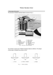
USER’S MANUAL
HR Series Portable Rockwell/Superficial Rockwell Hardness Tester
HBR Series Brinell & Rockwell Hardness Tester
Caution:
1. Safety goggles must be worn to prevent possible injury.
2. Gloves and the handing handle must be used during the hammer impact test.
Attention:
Check and confirm to bring the thin screw about 10-20mm up above the spiral tube
before testing.If not ,the force can not be loaded and the instrument may be broken.
1. Introduction
The HB-150 Portable Brinell HardnessTester is
designed following the Brinell hardness test method.
The test force is controlled by a shear pin. After reading
the diameter of the indention with the reading microscope,
the Brinell hardness number can be obtained from the
lookup table.
The HB-150 Portable Brinell Hardness Tester has
two types of application: C clamp and hammer impact
(see fig.1). It is capable of testing from small to very
large specimens. It is especially suitable for assemblies
Fig. 1 Portable Brinell Hardness Tester
inconve-nient to be takento the lab and not allowed to
be cut. The test can be completed in any dire-ction to
test the hardness of upper, lower and lateral part of the
specimen.
The test head itself can be used as a hammer impact
tester. It can perform the testing by touching one side of
the work piece. Its accuracy is much higher than any other
type hammer impact tester.
According to the similarity principle of Brinell
hardness testing, with testing force of 1580kg, indenter
diameter of 7.26mm, then F/D2 =30. The test condition
of the HB tester is equivalent to the standard Brinell
Fig. 2 Hammer Impact Hardness Tester
hardness test with 3000kgf and 10mm ball indenter.
The HB-150 Portable Brinell Hardness Tester can be
widely used to test the hardness of forgings, castings, steels,
nonferrous metal and its alloy products, and to test the hardness of annealed, normalizing and
temperedmechanical parts.
Compared to the rebound type hardness tester, the Brinell tester has many advantages
such as higher precision, fewer factors affecting accuracy and lower requirement on the
surface roughness. The test result meets the requirements of most drawings without
conversion and is more widely accepted in the international business.
Used as a self-product the operation of HB-1 hammer impact Brinell hardness tester can
be refered to hammer impact part of HB-150.
1
2. Principle and Structure
(a)
(b)
6 —— Test head (Indenter holder)
7 —— Rubber protective cap
8 —— Shear pin
9 —— Indenter
1 —— C clamp
2 —— Spiral tube
3 —— Thin screw
4 —— Handle
5 —— Anvil
The structure of the instrument is shown in Fig.3.
The instrument is composed of C Clamp, spriral tube, test head, thin screw, handle, anvil
and the forve transmission system in the spiral tube. See Fig.3 (a).
The sprial tube is used for clamping the specimen and the thin screw is for applying test
force. See Fig.3 (b).
The hammer impact Brinell hardness tester is composed of the test head which is taken
off from the spiral tube, impact cylinder, holding handle and hammer. See Fig.2.
The principle of the instrument and inside structure of the test head are shown in Fig.4.
A shear pin is place in the horizontal hole on the test head. The indenter is pushed into
the bottom hole and its top touches shear pin. The test head is placed into the spiral tube (C
clamp) or impact cylinder (hammer impact).
When the test force is applied on top of the test head, the force is transmitted to the
indenter through the shear pin which presses indenter against the specimen. As soon as the
test force reaches 1580kg, the shear pin is cut into three segments by the cutting system
comprising the test head and the indenter. The
excessive force will not be transmitted to the
indenter as it withdraws into bottom hole of the
test head,and a round indentation will remain
on the surface of the specimen.
The indentationdiameter is measured with a reading
microscope, and the Brinell hardness number can be
obtained from the lookup table.
Fig. 4 Principe of the instrument
2
3. Technical Parameters
Test force:
1580kg;
Tolerance of test force:
<0.5%;
Accuracy:
C clamp In accordance with ISO6506
Hammer impact <5%
Indenter:
Φ7.26mm steel spherical surface indenter
(range: 100-400HB)
Φ4.0mm carbide spherical surface indenter (Optional)
(range: 400-650HB)
Opening size (H×D):
150mm×100mm
Net weight:
C clamp:
4.2kg
Hammer impact: 0.8kg
4. Operation Instructions
4.1 Instructions for the C Clamp Tester
The portable hardness testers includes the C Clamp, which is a kind of static test.
4.1.1 Indenter Selection. According to the expected hardness of the testing piece, choose the
suitable indenter. When testing the softer metal with the hardness lower than 400HB, choose
the steel spherical surface indenter with a diameter of 7.26mm; when testing hard steel
materials with the hardness higher than 400HB, choose the carbide spherical surface indenter
with a diameter of 4.0mm.
4.1.2 Anvil Selection. Choose an appropriate anvil to fit the shape and size of the specimen,
and install it in the bottom of the C Clamp. The flat anvil is for flat blocks or sheets; the V
anvil is for cylinders; the dome anvil is for curled sheets and pipes. The right anvil should
provide a firm support for the specimen, and there should be no slipping or distortion when
the force is applied.
4.1.3 Put a shear pin into the horizontal hole of the test head. Push the indenter into the
bottom hole of the test head with the spherical surface out and make sure it contacts the shear
pin. Cover the bottom of the test head with the rubber protective cap, in order that the cap
contacts the bottom of the test head closely, the indenter should come out from the central
hole of protective cap. The purposes of the cap are to protect the surface of the specimen and
prevent shear pin from spattering.
4.1.4 Install the test head into the bottom of the spiral tube.
4.1.5 Check and confirm to bring the thin screw which is under the handle about 10-20mm up
above the spiral tube. If not, operate according to Step 4.1.9.
4.1.6 Place the specimen in the opening of the C Clamp. Make sure the back of the specimen
completely contacts the anvil, and the indenter is perpendicular to the tested surface of the
specimen. Rotate the handle clockwise, drive the spiral tube down and clamp the tester on the
specimen. After the indenter reaches the specimen, continue rotating the handle to drive the
thin screw down until a breaking sound is heard, which means the shear pin is broken and the
force application is completed.
4.1.7 Rotate the handle counterclockwise and raise the spiral tube.
4.1.8 Take out the test head from the lower part of the spiral tube and take off the rubber
protective cap. Remove the broken shear pin and push the indenter out with the pin removal
tool.
3
4.1.9 Hold the lower part of the spiral tube, rotate the handle counterclockwise and raise the
thin screw up about 10-20mm above the spiral tube. Do make sure to raise the thin screw up
after each test.
4.1.10 Use the reading microscope to read the indentation diameter in two perpendicular
directions. Refer to Section 4.4 for the instructions of the reading microscope.
4.1.11 Check Appendix A or Appendix B with the average indentation diameter to get the
Brinell hardness value.
4.2 Instructions for the Hammer Impact Tester
The hammer impact tester does not include the C Clamp. It only includes the test
head,impact cylinder, holding handle and hammer. The hardness testing by hammer impact
tester is a kind of dynamic hardness testing. The hardness testing by hammer impact tester is a
kind of dynamic hardness testing.
4.2.1 Put a shear pin into the horizontal hole of the test head. Push the indenter into the
bottom hole of the test head with the spherical surface out and make sure it contacts the shear
pin.
4.2.2 Place the test head into impact cylinder.
4.2.3 Put the handle on the specimen. Put the impact cylinder into the handle, and make sure
the bottom of the impact cylinder rest firmly on the specimen.
4.2.4 Use the flat side of a 3 lb (1.5kg) hammer to apply a sharp blow on top of the test head.
The shear pin must be broken at the first blow. If the pin is not broken, another blow must be
applied in order to remove the pin, and the result must be ignored.
4.2.5 Take out the test head and remove the broken shear pin with the pin removal tool. Push
the indenter outward off the hole of the shear pin. If the shear pin is not completely broken off,
the test should be considered as invalid. Install a new shear pin and test again. Be sure to
break off the shear pin completely.
4.2.6 The dynamic test with a bigger force may result in an elliptic indentation. The diameter
of the indentation must be measured in at least two directions. Use the smallest diameter as
the valid one to check Appendix C, D or E for the Brinell hardness value.
4.3 Usage of the Reading Microscope
4.3.1 Look into the ocular with enough light and turn the barrel dial to make the vertical lens
line aligned with the “0” scale of the horizontal line. Meanwhile the long scale mark should
rest on “0” scale of the barrel dial.
4.3.2Put the reading microscope on the test piece to locate the indentation in the centre of the
viewing field of the microscope. Move the microscope to make the vertical line tangential to
the left edge of the indentation. Press the bottom of the reading microscope, turn the barrel
dial to make the vertical line tangential to the right edge of the indentation.
4.3.3Read the integral part (mm) of the indentation diameter from the horizontal scale mark,
then read the 2-digit decimal part of the indentation diameter from the barrel dial.
4.3.3When the vertical line is aligned with the “0” scale mark of the horizontal line, but the
“0” scale mark of the barrel dial is not aligned with the long scale mark, it means the
microscope is inaccurate. Adjustment should be made as follow:
a. Make the vertical lens line aligned with the “0” scale mark of the horizontal line.
4
b. Unscrew the three screws on the barrel dial.
c. Make the “0” scale mark on the barrel dial exactly aligned with the long scale mark.
d. Fasten the three screws.
5. Verification
The Brinell standard hardness block is used to calibrate the Brinell tester. The test result
on the test block should be close to the hardness of testing pieces.
Impact on testing blocks by hardness tester and get indentation, measuring the average
diameter value of indentation by microscope, then get the hardness value aftercheck appendix.
The error of this tester is the difference between this value and the value of testing block.
6. Cautions and Tips
6.1 When testing with the C Clamp, the thin screw must be brought about 20mm up
before testing. If not, the thin screw cannot drive the test force on the specimen and it
may bedamaged.
6.2 Do not disassemble the spiral tube. The tester will be damaged permanently and
the warranty will be void.
6.3 When the hardness of specimen is greater than 400HB, the carbide indenter
must be used.
6.4 Indenters are normal wear items and are not covered by the warranty. The
carbide indenter is more brittle and more easily broken than the steel indenter.
6.5 To protect the specimen surface from the impact cylinder, a cardboard with a
hole bigger than indenter can be placed between the impact cylinder and the
specimen.
6.6 Wear safety goggles and gloves to prevent possible injury.6. Cautions and Tips
7. Factors Affecting Testing Accuracy
7.1 Specimen Surface
The surface of the specimen should be smooth and clean for the best accuracy. The rough
surface makes the indentation edge blurry and affects the measurement of the indentation
diameters which will increase the dispersity of the test result. The rough surface can also
reduce the specimen’s resistance against the pressing indenter which will result in a lower
Brinell hardness value. Use a sand paper or polish machine to polish the part to be tested for
better accuracy.If the oxide coating, decarbonization layer, dust or dirt remains on the
specimen surface,the hardness testing will be invalid. Remove those things before testing.
7.2 Supporting of the specimen
Carefully clean the bearing surface of the specimen to ensure that the impurities or dirt
like oxide coating, grease and dust can not be found between the back side of the specimen
5
and the supporting anvil.
Choose the proper anvil, proper testing surface and the bearing surface to ensure that the
specimen is firmly supported without sliding or deformation when the test force is applied.
7.3 Impact Effect of Hammer Impact Tester
The specimen may move under the test force when the hammer impact tester is being
used which will affect the testing result.
When testing with the hammer impact hardness tester, loading and unloading of the test
force is finished in an instant, and the dwell time of the greatest test force does not reach the
set time of the ordinary Brinell hardness testing. This will affect the testing result.
As above-mentioned, the operator should regularly make comparison tests with the
standard Brinell hardness testers in order to ensure the accuracy of the testing result. The
static (C Clamp) tester can be used as the comparison tester to verify the test result of the
hammer impact hardness tester.
The accuracy of the hammer impact Brinell hardness tester can be lowered by impact
effect, so the prior selection should be static (C Clamp) testing if the specimen size allows.
8. Factors Affecting Testing Accuracy
Brinell hardness test can reflect the average mechanical properties of a large region of
the specimen, so there is a close relation between the Brinell hardness and other mechanical
properties of materials, especially tensile strength.
The approximate conversion equation is:
σb= K*HB
in this equation: σb is the tensile strength value in MPa;
K is a constant depending on the material.
The tensile strength of materials can be obtained indirect by testing the Brinell hardness
with its approximate value obtained by conversion, which is of great importance in practical
production by both increasing work efficiency and saving material as well.
The conversion of hardness-tensile strength of some metallic materials is shown below:
Material
Steel
Brinell Hardness Value
125~175
>175
Approximate Conversion
σb ≈ 3.43HB (MPa)
σb ≈ 3.63HB (MPa)
Cast aluminum alloy
σb ≈ 2.6HB (MPa)
annealed brass, bronze
Brass, bronze after being
cold-processed
σb ≈ 5.5HB (MPa)
σb ≈ 4.0HB (MPa)
6
9. Standard Package
Standard package of PHB-150Brinell
Hardness Tester
1 Tester
1 steel ball indenter
1 Flat anvil
1 V anvil
1 Brinell standard hardness block
1 Holding handle
1 Pin removal tool
Standard package of PHB-1 Brinell
Hardness Tester
1 Test head
1 Impact cylinder
1 Indenter
1 Holding handle
1 Pack of shear pins (250 pieces)
1 Peading microscope 20x
1 Brinell standard hardness block
1 Pin removal tool
1 Carryingcase
1 Manual
1 Pack of shear pins (250 pieces)
1 Impact cylinder
1 Reading microscope 20x
2 Rubber protective caps
1 Carrying case
1 Manual
10. Optional Accessories and Spare Parts
Steel ball indenter
Carbide ball indenter
Brinell standard hardness block
Test head
Shear pins (a pack of 250pcs)
Hemispherical spot anvil (used for testing tubing or curled specimens)
Small flat anvil (used for testing small specimens)
40x reading microscope (used for Φ4.0mm carbide indenter)
3 lb hammer
7
Appendix A :Indentation—Brinell Hardness Table 1
C Clamp Tester Steel Indenter ∮7.26mm
Indentation
Diameter
mm
Hardness
HB
Indentation
Diameter
mm
Indentation
Diameter
mm
Hardness
HB
Hardness
HB
Indentation
Diameter
mm
Hardness
HB
2.00
2.01
2.02
2.03
2.04
480.0
475.6
471.2
466.8
462.4
2.35
2.36
2.37
2.38
2.39
349.0
346.0
343.0
340.0
337.0
2.70
2.71
2.72
2.73
2.74
264.0
262.0
260.0
258.0
256.0
3.05
3.06
3.07
3.08
3.09
204.0
202.6
201.2
199.8
198.4
2.05
2.06
2.07
2.08
2.09
458.0
454.0
450.0
446.0
442.0
2.40
2.41
2.42
2.43
2.44
334.0
331.4
328.8
326.2
323.6
2.75
2.76
2.77
2.78
2.79
254.0
252.2
250.4
248.6
246.8
3.10
3.11
3.12
3.13
3.14
197.0
195.6
194.2
192.8
191.4
2.10
2.11
2.12
2.13
2.14
438.0
434.2
430.4
426.6
422.8
2.45
2.46
2.47
2.48
2.49
321.0
318.4
315.8
313.2
310.6
2.80
2.81
2.82
2.83
2.84
245.0
243.2
241.4
239.6
237.8
3.15
3.16
3.17
3.18
3.19
190.0
188.8
187.6
186.4
185.2
2.15
2.16
2.17
2.18
2.19
419.0
415.4
411.8
408.2
404.6
2.50
2.51
2.52
2.53
2.54
308.0
305.8
303.6
301.4
299.2
2.85
2.86
2.87
2.88
2.89
236.0
234.4
232.8
231.2
229.6
3.20
3.21
3.22
3.23
3.24
184.0
182.8
181.6
180.4
179.2
2.20
2.21
2.22
2.23
2.24
401.0
397.4
393.8
390.2
386.6
2.55
2.56
2.57
2.58
2.59
297.0
294.6
292.2
289.8
287.4
2.90
2.91
2.92
2.93
2.94
228.0
226.4
224.8
223.2
221.6
3.25
3.26
3.27
3.28
3.29
178.0
176.8
175.6
174.4
173.2
2.25
2.26
2.27
2.28
2.29
383.0
379.4
375.8
372.2
368.6
2.60
2.61
2.62
2.63
2.64
285.0
282.8
280.6
278.4
276.2
2.95
2.96
2.97
2.98
2.99
220.0
218.4
216.8
215.2
213.6
3.30
3.31
3.32
3.33
3.34
172.0
171.0
170.0
169.0
168.0
2.30
2.31
2.32
2.33
2.34
365.0
361.8
358.6
355.4
352.2
2.65
2.66
2.67
2.68
2.69
274.0
272.0
270.0
268.0
266.0
3.00
3.01
3.02
3.03
3.04
212.0
210.4
208.8
207.2
205.6
3.35
3.36
3.37
3.38
3.39
167.0
166.0
165.0
164.0
163.0
8
C Clamp Tester Steel Indenter ∮7.26mm
Indentation
Diameter
mm
Hardness
HB
Indentation
Diameter
mm
Indentation
Diameter
mm
Hardness
HB
Hardness
HB
Indentation
Diameter
mm
Hardness
HB
3.40
3.41
3.42
3.43
3.44
162.0
161.0
160.0
159.0
158.0
3.59
3.60
3.61
3.62
3.63
143.0
142.0
141.2
140.4
139.6
3.78
3.79
3.80
3.81
3.82
127.6
126.8
126.0
125.2
124.4
3.97
3.98
3.99
4.00
4.01
112.4
111.6
110.8
110.0
109.2
3.45
3.46
3.47
3.48
3.49
157.0
156.0
155.0
154.0
153.0
3.64
3.65
3.66
3.67
3.68
138.8
138.0
137.2
136.4
135.6
3.83
3.84
3.85
3.86
3.87
123.6
122.8
122.0
121.2
120.4
4.02
4.03
4.04
4.05
4.06
108.4
107.6
106.8
106.0
105.4
3.50
3.51
3.52
3.53
3.54
152.0
151.0
150.0
149.0
148.0
3.69
3.70
3.71
3.72
3.73
134.8
134.0
133.2
132.4
131.6
3.88
3.89
3.90
3.91
3.92
119.6
118.8
118.0
117.2
116.4
4.07
4.08
4.09
4.10
4.11
104.8
104.2
103.6
103.0
102.4
3.55
3.56
3.57
3.58
147.0
146.0
145.0
144.0
3.74
3.75
3.76
3.77
130.8
130.0
129.2
128.4
3.93
3.94
3.95
3.96
115.6
114.8
114.0
113.2
4.12
4.13
4.14
4.15
101.8
101.2
100.6
100.0
Appendix B: Indentation—Brinell Hardness Table 2
C Clamp Tester—Carbide Indenter ∮4mm
Diameter
HB
Diameter
HB
Diameter
HB
Diameter
HB
1.45
1.46
1.47
1.48
1.49
742.0
735.2
728.4
721.6
714.8
1.71
1.72
1.73
1.74
1.75
614.0
608.3
602.5
596.8
591.0
1.97
1.98
1.99
2.00
2.01
471.9
466.9
462.0
457.0
452.8
2.23
2.24
2.25
2.26
2.27
366.8
363.4
360.0
356.8
353.6
1.50
1.51
1.52
1.53
1.54
708.0
701.4
694.8
688.2
681.6
1.76
1.77
1.78
1.79
1.80
584.9
578.8
572.8
566.7
560.6
2.02
2.03
2.04
2.05
2.06
448.5
444.3
440.0
435.8
431.6
2.28
2.29
2.30
2.31
2.32
350.4
347.2
344.0
340.8
337.6
1.55
1.56
1.57
1.58
1.59
675.0
673.5
672.0
668.9
665.7
1.81
1.82
1.83
1.84
1.85
555.5
550.4
545.4
540.3
535.2
2.07
2.08
2.09
2.10
2.11
427.5
423.3
419.2
415.0
411.0
2.33
2.34
2.35
2.36
2.37
334.4
331.2
328.0
325.5
323.0
1.60
1.61
1.62
1.63
1.64
662.6
658.9
655.2
651.4
647.7
1.86
1.87
1.88
1.89
1.90
529.4
523.7
517.9
512.2
506.4
2.12
2.13
2.14
2.15
2.16
407.0
403.0
399.0
395.0
391.4
2.38
2.39
2.40
2.41
2.42
320.4
317.9
315.4
312.6
309.7
1.65
1.66
1.67
1.68
1.69
644.0
639.2
634.3
629.5
624.6
1.91
1.92
1.93
1.94
1.95
501.5
496.6
491.6
486.7
481.8
2.17
2.18
2.19
2.20
2.21
387.8
384.2
380.6
377.0
373.6
2.43
2.44
2.45
306.9
304.0
301.2
1.70
619.8
1.96
476.8
2.22
370.2
9
Appendix C: Indentation—Brinell Hardness Table 3
Diameter
Hammer Impact—Steel Ball Indenter ∮7.26mm—for Steel
HB
Diameter
HB
Diameter
HB
Diameter
HB
2.05
2.06
2.07
2.08
2.09
484.0
479.2
474.4
469.6
464.8
2.49
2.50
2.51
2.52
2.53
315.4
312.0
309.0
306.0
303.0
2.93
2.94
2.95
2.96
2.97
217.6
215.8
214.0
212.4
210.8
3.37
3.38
3.39
3.40
3.41
155.2
153.8
152.4
151.0
149.8
2.10
2.11
2.12
2.13
2.14
460.0
455.8
451.6
447.4
443.2
2.54
2.55
2.56
2.57
2.58
300.0
297.0
294.2
291.4
288.6
2.98
2.99
3.00
3.01
3.02
209.2
207.6
206.0
204.4
202.8
3.42
3.43
3.44
3.45
3.46
148.6
147.4
146.2
145.0
143.6
2.15
2.16
2.17
2.18
2.19
439.0
435.0
431.0
427.0
423.0
2.59
2.60
2.61
2.62
2.63
285.8
283.0
280.8
278.6
276.4
3.03
3.04
3.05
3.06
3.07
201.2
199.6
198.0
196.6
195.2
3.47
3.48
3.49
3.50
3.51
142.2
140.8
139.4
138.0
136.8
2.20
2.21
2.22
2.23
2.24
419.0
415.2
411.4
407.6
403.8
2.64
2.65
2.66
2.67
2.68
274.2
272.0
270.0
268.0
266.0
3.08
3.09
3.10
3.11
3.12
193.8
192.4
191.0
189.6
188.2
3.52
3.53
3.54
3.55
3.56
135.6
134.4
133.2
132.0
130.6
2.25
2.26
2.27
2.28
2.29
400.0
396.4
392.8
389.2
385.6
2.69
2.70
2.71
2.72
2.73
264.0
262.0
260.0
258.0
256.0
3.13
3.14
3.15
3.16
3.17
186.8
185.4
184.0
182.6
181.2
3.57
3.58
3.59
3.60
3.61
129.2
127.8
126.4
125.0
123.8
2.30
2.31
2.32
2.33
2.34
382.0
378.4
374.8
371.2
367.6
2.74
2.75
2.76
2.77
2.78
254.0
252.0
250.0
248.0
246.0
3.18
3.19
3.20
3.21
3.22
179.8
178.4
177.0
175.8
174.6
3.62
3.63
3.64
3.65
3.66
122.6
121.4
120.2
119.0
117.6
2.35
2.36
2.37
2.38
2.39
364.0
360.4
356.8
353.2
349.6
2.79
2.80
2.81
2.82
2.83
244.0
242.0
240.0
238.0
236.0
3.23
3.24
3.25
3.26
3.27
173.4
172.2
171.0
169.6
168.2
3.67
3.68
3.69
3.70
3.71
116.2
114.8
113.4
112.0
110.8
2.40
2.41
2.42
2.43
2.44
346.0
342.6
339.2
335.8
332.4
2.84
2.85
2.86
2.87
2.88
234.0
232.0
230.2
228.4
226.6
3.28
3.29
3.30
3.31
3.32
166.8
165.4
164.0
162.8
161.6
3.72
3.73
3.74
3.75
3.76
109.6
108.4
107.2
106.0
104.6
2.45
2.46
2.47
2.48
329.0
325.6
322.2
318.8
2.89
2.90
2.91
2.92
224.8
223.0
221.2
219.4
3.33
3.34
3.35
3.36
160.4
159.2
158.0
156.6
3.77
3.78
3.79
3.80
103.2
101.8
100.4
99.0
10
Appendix D: Indentation—Brinell Hardness Table 4
Diameter
Hammer Impact—Steel Ball Indenter ∮7.26mm—for Cast Iron
HB
Diameter
HB
Diameter
HB
Diameter
HB
2.50
2.51
2.52
2.53
2.54
308.0
305.8
303.6
301.4
299.2
2.84
2.85
2.86
2.87
2.88
237.8
236.0
234.4
232.8
231.2
3.18
3.19
3.20
3.21
3.22
186.4
185.2
184.0
182.8
181.6
3.52
3.53
3.54
3.55
3.56
150.0
149.0
148.0
147.0
146.0
2.55
2.56
2.57
2.58
2.59
297.0
294.6
292.2
289.8
287.4
2.89
2.90
2.91
2.92
2.93
229.6
228.0
226.4
224.8
223.2
3.23
3.24
3.25
3.26
3.27
180.4
179.2
178.0
176.8
175.6
3.57
3.58
3.59
3.60
3.61
145.0
144.0
143.0
142.0
141.2
2.60
2.61
2.62
2.63
2.64
285.0
282.8
280.6
278.4
276.2
2.94
2.95
2.96
2.97
2.98
221.6
220.0
218.4
216.8
215.2
3.28
3.29
3.30
3.31
3.32
174.4
173.2
172.0
171.0
170.0
3.62
3.63
3.64
3.65
3.66
140.4
139.6
138.8
138.0
137.2
2.65
2.66
2.67
2.68
2.69
274.0
272.0
270.0
268.0
266.0
2.99
3.00
3.01
3.02
3.03
213.6
212.0
210.4
208.8
207.2
3.33
3.34
3.35
3.36
3.37
169.0
168.0
167.0
166.0
165.0
3.67
3.68
3.69
3.70
3.71
136.4
135.6
134.8
134.0
133.2
2.70
2.71
2.72
2.73
2.74
264.0
262.0
260.0
258.0
256.0
3.04
3.05
3.06
3.07
3.08
205.6
204.0
202.6
201.2
199.8
3.38
3.39
3.40
3.41
3.42
164.0
163.0
162.0
161.0
160.0
3.72
3.73
3.74
3.75
3.76
132.4
131.6
130.8
130.0
129.2
2.75
2.76
2.77
2.78
2.79
254.0
252.2
250.4
248.6
246.8
3.09
3.10
3.11
3.12
3.13
198.4
197.0
195.6
194.2
192.8
3.43
3.44
3.45
3.46
3.47
159.0
158.0
157.0
156.0
155.0
3.77
3.78
3.79
3.80
3.81
128.4
127.6
126.8
126.0
125.2
2.80
2.81
2.82
2.83
245.0
243.2
241.4
239.6
3.14
3.15
3.16
3.17
191.4
190.0
188.8
187.6
3.48
3.49
3.50
3.51
154.0
153.0
152.0
151.0
3.82
3.83
3.84
3.85
124.4
123.6
122.8
122.0
11
Appendix E: Indentation—Brinell Hardness Table 5
Diameter
HB
1.55
742.0
Hammer Impact—Carbide Indenter ∮4mm
Diameter
HB
Diameter
HB
Diameter
HB
1.79
596.0
2.03
462.9
2.27
359.4
1.56
1.80
589.8
2.04
457.8
2.28
355.6
1.57
1.81
585.0
2.05
452.8
2.29
351.8
1.58
1.82
580.2
2.06
447.8
2.30
348.0
1.59
1.83
575.4
2.07
442.9
2.31
344.6
1.60
1.84
570.6
2.08
437.9
2.32
341.2
1.61
1.85
565.8
2.09
433.0
2.33
337.8
1.62
1.86
559.3
2.10
428.0
2.34
334.4
1.63
1.87
552.8
2.11
423.7
2.35
331.0
1.64
1.88
546.4
2.12
419.4
2.36
327.3
1.65
708.0
1.89
539.9
2.13
415.2
2.37
323.6
1.66
1.90
533.4
2.14
410.9
2.38
319.8
1.67
1.91
528.1
2.15
406.6
2.39
316.1
1.68
1.92
522.8
2.16
402.1
2.40
312.4
1.69
1.93
517.4
2.17
397.6
2.41
309.5
673.0
1.70
639.8
1.94
512.1
2.18
393.0
2.42
306.6
1.71
636.0
1.95
506.8
2.19
388.5
2.43
303.8
1.72
632.2
1.96
501.0
2.20
384.0
2.44
300.9
1.73
628.4
1.97
495.3
2.21
380.6
2.45
298.0
1.74
624.6
1.98
489.5
2.22
377.2
2.46
294.6
1.75
620.8
1.99
483.8
2.23
373.8
2.47
291.3
1.76
614.6
2.00
478.0
2.24
370.4
2.48
287.9
1.77
608.4
2.01
473.0
2.25
367.0
2.49
284.6
1.78
602.2
2.02
467.9
2.26
363.2
2.50
281.2
12
Appendix F Conversion Value of Hardness and Strength of Ferrous Metal
Table A conversion value of hardness and strength of all kinds of steels
Hardness
Tensile strength σb/MPa
chrome molybdenum
steel
68.8
40.7
19.2
226
225
774
742
736
782
747
781
740
20.5
60.4
69.0
41.2
19.8
228
227
784
751
744
787
753
788
749
21.0
60.7
69.3
41.7
20.4
230
229
793
760
753
792
760
794
758
21.5
61.0
69.5
42.2
21.0
233
232
803
769
761
797
767
801
767
22.0
61.2
69.8
42.6
21.5
235
234
813
799
770
803
774
809
777
22.5
61.5
70.0
43.1
22.1
238
237
823
788
779
809
781
816
786
23.0
61.7
70.3
43.6
22.7
241
240
833
798
788
815
789
824
796
23.5
62.0
70.6
44.0
23.3
244
242
843
808
797
822
797
832
806
24.0
62.2
70.8
44.5
23.9
247
245
854
818
807
829
805
840
816
24.5
62.5
71.1
45.0
24.5
250
248
864
828
816
836
813
848
826
25.0
62.8
71.4
45.5
25.1
253
251
875
838
826
843
822
856
837
25.5
63.0
71.6
45.9
25.7
256
254
886
848
837
851
831
850
865
847
26.0
63.3
71.9
46.4
26.3
259
257
897
859
847
859
840
859
874
858
26.5
63.5
72.2
46.9
26.9
262
260
908
870
858
867
850
869
883
868
27.0
63.8
72.4
47.3
27.5
266
263
919
880
869
876
860
870
893
879
27.5
64.0
72.7
47.8
28.1
269
266
930
891
880
885
870
890
902
890
28.0
64.3
73.0
48.3
28.7
273
269
942
902
892
894
880
901
912
901
28.5
64.6
73.3
48.7
29.3
276
273
954
914
903
904
891
912
922
913
29.0
64.8
73.5
49.2
29.9
280
276
965
925
915
914
902
923
933
924
29.5
65.1
73.8
49.7
30.5
284
280
977
937
928
924
913
935
943
936
30.0
65.3
74.1
50.2
31.1
288
283
989
948
940
935
924
947
954
947
30.5
65.6
74.4
50.6
31.7
292
287
1002
960
953
946
936
959
965
959
31.0
65.8
74.7
51.1
32.3
296
291
1014
972
966
957
948
972
977
971
31.5
66.1
74.9
51.6
32.9
300
294
1027
984
980
969
961
985
989
983
32.0
66.4
75.2
52.0
33.5
304
298
1039
996
993
981
974
999
1001
996
32.5
66.6
75.5
52.5
34.1
308
302
1052
1009
1007
994
987
1012
1013
1008
33.0
66.9
75.8
53.0
34.7
313
306
1065
1022
1022
1007
1001
1027
1026
1021
33.5
67.1
76.1
53.4
35.3
317
310
1078
1034
1036
1020
1015
1041
1039
1034
34.0
67.4
76.4
53.9
35.9
321
314
1092
1048
1051
1034
1029
1056
1052
1047
34.5
67.7
76.7
54.4
36.5
326
318
1105
1064
1067
1048
1043
1071
1066
1060
35.0
67.9
77.0
54.8
37.0
331
323
1119
1074
1082
1063
1058
1087
1079
1074
35.5
67.9
77.0
55.3
37.6
335
327
1133
1088
1098
1078
1074
1103
1094
1087
HR15N HR30N HR45N
HV
HBS
HBW
13
Stainless steel
Chrome nickel steel
Super high strength
steel
Chrome-vanadium
steel
60.2
Vickers
chromansil
Chrome steel
20.0
Superficial Rockwell
chromium nickel
molybdenum steel
HRA
Carbon steel
Brinell
(F/D2=30)
HRC
Rockwell
Hardness
Tensile strength σb/MPa
Chrome-vanadium
steel
Chrome nickel steel
chrome molybdenum
steel
chromium nickel
molybdenum steel
chromansil
36.0
68.4
77.5
55.8
38.2
340
332
1147
1102
1114
1093
1090
1119
1108
1101
36.5
68.7
77.8
56.2
38.8
345
336
1162
1116
1131
1109
1106
1136
1123
1116
37.0
69.0
78.1
56.7
39.4
350
341
1117
1131
1148
1125
1122
1153
1139
1130
37.5
69.2
78.4
57.2
40.0
355
345
1192
1146
1165
1142
1139
1171
1155
1145
38.0
69.5
78.7
57.6
40.6
360
350
1207
1161
1183
1159
1157
1189
1171
1161
38.5
69.7
79.0
58.1
41.2
365
355
1222
1176
1201
1177
1174
1207
1187
1170
1176
39.0
70.0
79.3
58.6
41.8
371
360
1238
1192
1219
1195
1192
1226
1204
1195
1193
39.5
70.3
79.6
59.0
42.4
376
365
1254
1208
1238
1214
1211
1245
1222
1219
1209
40.0
70.5
79.9
59.5
43.0
381
370
370
1271
1225
1257
1233
1230
1265
1240
1243
1226
40.5
70.8
80.2
60.0
43.6
387
375
375
1288
1242
1276
1252
1249
1285
1258
1267
1244
41.0
71.1
80.5
60.4
44.2
393
380
381
1305
1260
1296
1273
1269
1306
1277
1290
1262
41.5
71.3
80.8
60.9
44.8
398
385
386
1322
1278
1317
1293
1289
1327
1296
1313
1280
42.0
71.6
81.1
61.3
45.4
404
391
392
1340
1296
1337
1314
1310
1348
1316
1336
1299
42.5
71.8
81.4
61.8
45.9
410
396
397
1359
1315
1358
1336
1331
1370
1336
1359
1319
43.0
72.1
81.7
62.3
46.5
416
401
403
1378
1335
1380
1358
1353
1392
1357
1381
1339
43.5
72.4
82.0
62.7
47.1
422
407
409
1397
1355
1401
1380
1375
1415
1378
1404
1361
44.0
72.6
82.3
63.2
47.7
428
413
415
1417
1376
1424
1404
1397
1439
1400
1427
1383
44.5
72.9
82.6
63.6
48.3
435
418
422
1438
1398
1446
1427
1420
1462
1422
1450
1405
45.0
73.2
82.9
64.1
48.9
441
424
428
1459
1420
1469
1451
1444
1487
1445
1473
1429
45.5
73.4
83.2
64.6
49.5
448
430
435
1481
1444
1493
1476
1468
1512
1469
1496
1453
46.0
73.7
83.5
65.0
50.1
454
436
441
1503
1468
1517
1502
1492
1537
1493
1520
1479
46.5
73.9
83.7
65.5
50.7
461
442
448
1526
1493
1541
1527
1517
1563
1517
1544
1505
47.0
74.2
84.0
65.9
51.2
468
449
455
1550
1519
1566
1554
1542
1589
1543
1569
1533
47.5
74.5
84.3
66.4
51.8
475
463
1575
1546
1591
1581
1568
1616
1569
1594
1562
48.0
74.7
84.6
66.8
52.4
482
470
1600
1574
1617
1608
1595
1643
1595
1620
1592
48.5
75.0
84.9
67.3
53.0
489
478
1626
1603
1643
1636
1622
1671
1623
1646
1623
49.0
75.3
85.2
67.7
53.6
497
486
1653
1633
1670
1665
1649
1699
1651
1674
1655
49.5
75.5
85.5
68.2
54.2
504
494
1681
1665
1697
1695
1677
1728
1679
1702
1689
50.0
75.8
85.7
68.6
54.7
512
502
1710
1698
1724
1724
1706
1758
1709
1731
1725
50.5
76.1
86.0
69.1
55.3
520
510
1732
1752
1755
1735
1788
1739
1761
51.0
76.3
86.3
69.5
55.9
527
518
1768
1780
1786
1764
1819
1770
1792
51.5
76.6
86.6
70.0
56.5
535
527
1806
1809
1818
1794
1850
1801
1824
52.0
76.9
86.8
70.4
57.1
544
535
1845
1839
1850
1825
1881
1834
1857
52.5
77.1
87.1
70.9
57.6
552
544
1869
1883
1856
1914
1867
1892
Superficial Rockwell
Vickers
HR15N HR30N HR45N
HV
HBS
HBW
14
Stainless steel
Chrome steel
Super high strength
steel
HRA
Carbon steel
Brinell
(F/D2=30)
HRC
Rockwell
Hardness
Tensile strength σb/MPa
Super high strength
steel
1951
1936
1966
1961
1986
1971
2006
577
1993
2022
2008
2047
596
585
2026
2058
2045
2090
61.1
606
593
2135
73.9
61.7
615
601
2181
89.1
74.4
62.2
625
608
2230
79.5
89.4
74.8
62.8
635
616
2281
57.5
79.8
89.6
75.2
63.4
645
622
2334
58.0
80.1
89.8
75.6
63.9
655
628
2390
58.5
80.3
90.0
76.1
64.5
666
634
2448
59.0
80.6
90.2
76.5
65.1
676
639
2509
59.5
80.9
90.4
76.9
65.6
687
643
2572
60.0
81.2
90.6
77.3
66.2
698
647
2639
60.5
81.4
90.8
77.7
66.8
710
650
61.0
81.7
91.0
78.1
67.3
721
61.5
82.0
91.2
78.6
67.9
733
62.0
82.2
91.4
79.0
68.4
745
62.5
82.5
91.5
79.4
69.0
757
63.0
82.8
91.7
79.8
69.5
770
63.5
83.1
91.8
80.2
70.1
782
64.0
83.3
91.9
80.6
70.6
795
64.5
83.6
92.1
81.0
71.2
809
65.0
83.9
92.2
81.3
71.7
822
65.5
84.1
836
66.0
84.4
850
66.5
84.7
865
67.0
85.0
879
67.5
85.2
894
68.0
85.5
909
87.4
71.3
58.3
561
552
1899
1917
1888
53.5
77.7
87.6
71.8
58.8
569
561
1930
54.0
77.9
87.9
72.2
59.4
578
569
54.5
78.2
88.1
72.6
59.9
587
55.0
78.5
88.4
73.1
60.5
55.5
78.7
88.6
73.5
56.0
79.0
88.9
56.5
79.3
57.0
HR15N HR30N HR45N
HV
HBS
HBW
15
Chrome steel
77.4
Vickers
Carbon steel
53.0
Superficial Rockwell
Stainless steel
chromansil
1929
chrome molybdenum
steel
1901
Chrome nickel steel
1947
HRA
Chrome-vanadium
steel
chromium nickel
molybdenum steel
Brinell
(F/D2=30)
HRC
Rockwell
Table B Conversion value of hardness and strength of mild steels
Hardness
Rockwell
Superficial Rockwell
Vickers
Brinell
HBS
Tensile
strength of
mild steels
σb/MPa
HRB
HR15T
HR30T
HR45T
HV
60.0
80.4
56.1
30.4
105
102
375
60.5
80.5
56.4
30.9
105
102
377
61.0
80.7
56.7
31.4
106
103
379
61.5
80.8
57.1
31.9
107
103
381
62.0
80.9
57.4
32.4
108
104
382
62.5
81.1
57.7
32.9
108
104
384
63.0
81.2
58.0
33.5
109
105
386
63.5
81.4
58.3
34.0
110
105
388
64.0
81.5
58.7
34.5
110
106
390
64.5
81.6
59.0
35.0
111
106
393
65.0
81.8
59.3
35.5
112
107
395
65.5
81.9
59.6
36.1
113
107
397
66.0
82.1
59.9
36.6
114
108
399
66.5
82.2
60.3
37.1
115
108
402
67.0
82.3
60.6
37.6
115
109
404
67.5
82.5
60.9
38.1
116
110
407
68.0
82.6
61.2
38.6
117
110
409
68.5
82.7
61.5
39.2
118
111
412
69.0
82.9
61.9
39.7
119
112
415
69.5
83.0
62.2
40.2
120
112
418
70.0
83.2
62.5
40.7
121
113
421
70.5
83.3
62.8
41.2
122
114
424
71.0
83.4
63.1
41.7
123
115
427
71.5
83.6
63.5
42.3
124
115
430
72.0
83.7
63.8
42.8
125
116
433
72.5
83.9
64.1
43.3
126
117
437
73.0
84.0
64.4
43.8
128
118
440
73.5
84.1
64.7
44.3
129
119
444
74.0
84.3
65.1
44.8
130
120
447
74.5
84.4
65.4
45.4
131
121
451
75.0
84.5
65.7
45.9
132
122
455
75.5
84.7
66.0
46.4
134
123
459
76.0
84.8
66.3
46.9
135
124
463
76.5
85.0
66.6
47.4
136
125
467
16
2
F/D =10
F/D2=30
Hardness
Rockwell
Superficial Rockwell
Vickers
Brinell
HBS
Tensile
strength of
mild steels
σb/MPa
HRB
HR15T
HR30T
HR45T
HV
77.0
85.1
67.0
47.9
138
126
471
77.5
85.2
67.3
48.5
139
127
475
78.0
85.4
67.6
49.0
140
128
480
78.5
85.5
67.9
49.5
142
129
484
79.0
85.7
68.2
50.0
143
130
489
79.5
85.8
68.6
50.5
145
132
493
80.0
85.9
68.9
51.0
146
133
498
80.5
86.1
69.2
51.6
148
134
503
81.0
86.2
69.5
52.1
149
136
508
81.5
86.3
69.8
52.6
151
137
513
82.0
86.5
70.2
53.1
152
138
518
82.5
86.6
70.5
53.6
154
140
523
83.0
86.8
70.8
54.1
156
152
529
83.5
86.9
71.1
54.7
157
154
534
84.0
87.0
71.4
55.2
159
155
540
84.5
87.2
71.8
55.7
161
156
546
85.0
87.3
72.1
56.2
163
158
551
85.5
87.5
72.4
56.7
165
159
557
86.0
87.6
72.7
57.2
166
161
563
86.5
87.7
73.0
57.8
168
163
570
87.0
87.9
73.4
58.3
170
164
576
87.5
88.0
73.7
58.8
172
166
582
88.0
88.1
74.0
59.3
174
168
589
88.5
88.3
74.3
59.8
176
170
596
89.0
88.4
74.6
60.3
178
172
603
89.5
88.6
75.0
60.9
180
174
609
90.0
88.7
75.3
61.4
183
176
617
90.5
88.8
75.6
61.9
185
178
624
91.0
89.0
75.9
62.4
187
180
631
91.5
89.1
76.2
62.9
189
182
639
92.0
89.3
76.6
63.4
191
184
646
92.5
89.4
76.9
64.0
194
187
654
93.0
89.5
77.2
64.5
196
189
662
93.5
89.7
77.5
65.0
199
192
670
17
F/D2=10
F/D2=30
Hardness
Rockwell
Superficial Rockwell
Vickers
Brinell
HBS
Tensile
strength of
mild steels
σb/MPa
HRB
HR15T
HR30T
HR45T
HV
94.0
89.8
77.8
65.5
201
195
678
94.5
89.9
78.2
66.0
203
197
686
95.0
90.1
78.5
66.5
206
200
695
95.5
90.2
78.8
67.1
208
203
703
96.0
90.4
79.1
67.6
211
206
712
96.5
90.5
79.4
68.1
214
209
721
97.0
90.6
79.8
68.6
216
212
730
97.5
90.8
80.1
69.1
219
215
739
98.0
90.9
80.4
69.6
222
218
749
98.5
91.1
80.7
70.2
225
222
758
99.0
91.2
81.0.
70.7
227
226
768
99.5
91.3
81.4
71.2
230
229
778
100.0
91.5
81.7
71.7
233
232
788
18
F/D2=10
F/D2=30