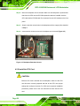
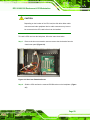
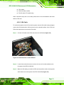
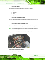
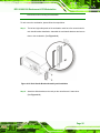
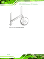
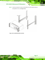
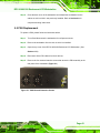
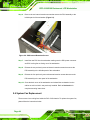
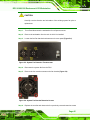
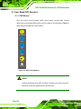
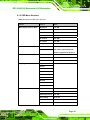
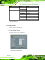
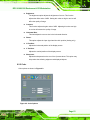
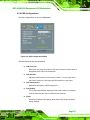
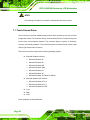
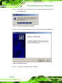
1
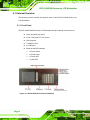
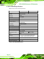
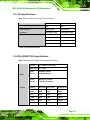
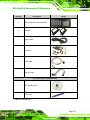
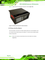
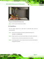
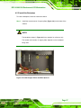
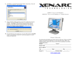
RPC-6106/6108 Rackmount LCD Workstation
RPC-6106/RPC-6108 LCD Workstation User Manual
Page i
RPC-6106/6108 Rackmount LCD Workstation
Revision
MODEL
RPC-6106/6108 4U 7-slot LCD Workstation
Revision Number
Description
Date of Issue
1.0
Initial release
March 2007
Page ii
RPC-6106/6108 Rackmount LCD Workstation
Copyright
COPYRIGHT NOTICE
The information in this document is subject to change without prior notice in order to
improve reliability, design and function and does not represent a commitment on the part
of the manufacturer.
In no event will the manufacturer be liable for direct, indirect, special, incidental, or
consequential damages arising out of the use or inability to use the product or
documentation, even if advised of the possibility of such damages.
This document contains proprietary information protected by copyright. All rights are
reserved. No part of this manual may be reproduced by any mechanical, electronic, or
other means in any form without prior written permission of the manufacturer.
TRADEMARKS
IBM PC is a registered trademark of International Business Machines Corporation. INTEL
is a registered trademark of INTEL Corporation. Other product names mentioned herein
are used for identification purposes only and may be trademarks and/or registered
trademarks of their respective owners.
Page iii
RPC-6106/6108 Rackmount LCD Workstation
Packing List
NOTE:
If any of the components listed in the checklist below are missing, please do not
proceed with the installation. Contact the IEI reseller or vendor you purchased
the RPC-6106/6108 LCD Workstation from or contact an IEI sales
representative directly. To contact an IEI sales representative, please send an
email to [email protected].
The items listed below should all be included in the RPC-6106/6108 Rackmount LCD
Workstation package.
1 x RPC-6106/6108 Rackmount LCD Workstation
2 x Handles
1 x Power cable
1 x Screw kit
1 x VGA cable
1 x RS-232 cable
For Touch Panel (T-R) Models only:
1 x TouchKit Driver CD
1 x Touch Pen
Images of the above items are shown in Section 4.2.3.
Page iv
RPC-6106/6108 Rackmount LCD Workstation
Table of Contents
1
INTRODUCTION..................................................................................................... 1
1.1 RPC-6106/6108 OVERVIEW ...................................................................................... 2
1.2 RPC-6106/6108 FEATURES ....................................................................................... 2
1.3 MODEL VARIATIONS ................................................................................................... 2
1.4 CERTIFICATION ........................................................................................................... 3
2
MECHANICAL OVERVIEW ................................................................................. 5
2.1 EXTERNAL OVERVIEW ............................................................................................... 6
2.1.1 Front Panel ........................................................................................................ 6
2.1.2 Rear Panel ......................................................................................................... 7
2.1.3 Side Panel .......................................................................................................... 7
2.1.4 Internal overview ............................................................................................... 8
2.2 PHYSICAL DIMENSIONS .............................................................................................. 8
2.2.1 General Physical Dimensions............................................................................ 8
2.2.2 RPC-6106 Physical Dimensions ........................................................................ 9
2.2.3 RPC-6108 Physical Dimensions ...................................................................... 10
3
DETAILED SPECIFICATIONS ............................................................................11
3.1 RPC-6106/6108 SPECIFICATIONS ............................................................................ 12
3.2 LCD SPECIFICATIONS .............................................................................................. 13
3.3 ACE-4525AP PSU SPECIFICATIONS ........................................................................ 13
3.4 RECOMMENDED IEI BACKPLANES, MOTHERBOARDS AND PSUS ............................. 14
4
INSTALLATION .................................................................................................... 15
4.1 INSTALLATION CONSIDERATIONS ............................................................................. 16
4.1.1 Installation Precautions ................................................................................... 16
4.1.2 Installation Prerequisites ................................................................................. 16
4.2 UNPACKING.............................................................................................................. 17
4.2.1 Packaging ........................................................................................................ 17
4.2.2 Unpacking Procedure ...................................................................................... 17
4.2.3 Packing List ..................................................................................................... 18
Page v
RPC-6106/6108 Rackmount LCD Workstation
4.3 PRE-INSTALLATION PREPARATION ............................................................................ 20
4.3.1 System Planning............................................................................................... 20
4.3.2 Tools ................................................................................................................. 21
4.4 INSTALLATION PROCEDURES .................................................................................... 21
4.4.1 Preinstalled Components ................................................................................. 21
4.4.2 User Installed Components.............................................................................. 21
4.4.3 Installation Steps.............................................................................................. 22
4.5 INSTALLING COMPONENTS INTO THE RPC-6106/6108............................................. 22
4.5.1 Remove the Top Cover ..................................................................................... 23
4.5.2 Remove the Drive Bracket ............................................................................... 24
4.5.3 Install Drives.................................................................................................... 25
4.5.4 Reinstall the Drive Brackets ............................................................................ 26
4.5.5 Install the Backplane........................................................................................ 27
4.5.6 Install the CPU Card ....................................................................................... 28
4.5.7 Install the PCI/ISA Expansion Card ................................................................ 30
4.5.8 Connect the Cables .......................................................................................... 30
4.5.8.1 VGA Cable................................................................................................ 31
4.5.8.2 PSU Cables ............................................................................................... 33
4.5.8.3 Disk Drive Ribbon Cables ........................................................................ 33
4.5.8.4 RS-232 Cable (T-R Models Only) ............................................................ 33
4.5.9 Close the Top Cover ......................................................................................... 34
4.6 MOUNTING THE RPC-6106/6108 RACKMOUNT WORKSTATION ............................... 34
5
MAINTENANCE.................................................................................................... 39
5.1 MAINTENANCE OVERVIEW....................................................................................... 40
5.2 CPU CARD REPLACEMENT ...................................................................................... 41
5.3 PCI/ISA EXPANSION CARD REPLACEMENT ............................................................. 41
5.4 BACKPLANE REPLACEMENT..................................................................................... 42
5.5 PSU REPLACEMENT ................................................................................................. 43
5.6 SYSTEM FAN REPLACEMENT .................................................................................... 44
5.7 DISK DRIVE REPLACEMENT ..................................................................................... 46
5.7.1 3.5” Disk Drive................................................................................................ 46
6
ON SCREEN DISPLAY (OSD) CONTROLS ...................................................... 47
6.1 USER MODE OSD STRUCTURE ................................................................................ 48
Page vi
RPC-6106/6108 Rackmount LCD Workstation
6.1.1 OSD Buttons..................................................................................................... 48
6.1.2 OSD Menu Structure ........................................................................................ 49
6.2 USING THE OSD....................................................................................................... 50
6.2.1 Main Display Features..................................................................................... 50
6.2.2 Color ................................................................................................................ 51
6.2.3 Language.......................................................................................................... 52
6.2.4 OSD Configurations......................................................................................... 53
6.2.5 Signal ............................................................................................................... 54
6.2.6 Backlight .......................................................................................................... 55
7
SOFTWARE DRIVER ........................................................................................... 57
7.1 TOUCH SCREEN DRIVER ........................................................................................... 58
7.2 DRIVER INSTALLATION ............................................................................................. 59
7.3 TOUCH PANEL DRIVER CONFIGURATION .................................................................. 67
A
CERTIFICATION .................................................................................................. 69
A.1 ROHS COMPLIANT.................................................................................................. 70
B
RECOMMENDED IEI BACKPLANES AND PSUS .......................................... 71
B.1 RPC-6106/6108 BACKPLANE OPTIONS................................................................... 72
B.2 POWER SUPPLY OPTIONS ......................................................................................... 72
INDEX.............................................................................................................................. 73
Page vii
RPC-6106/6108 Rackmount LCD Workstation
List of Figures
Figure 2-1: RPC-6106/6108 Front Panel (External) ....................................................6
Figure 2-2: RPC-6106/6108 14-Slot Rear Panel ..........................................................7
Figure 2-3: RPC-6106/6108 Side Panel........................................................................7
Figure 2-4: RPC-6106/6108 Internal Overview ............................................................8
Figure 2-5: RPC-6106 Physical Dimensions (millimeters) ........................................9
Figure 2-6: RPC-6108 Physical Dimensions (millimeters) ......................................10
Figure 4-1: Top Cover Retention Screws..................................................................23
Figure 4-2: Remove the Top Cover from the Chassis .............................................24
Figure 4-3: Drive Bracket Retention Screws ............................................................25
Figure 4-4: Install Copper Pillars and White Spacers..............................................27
Figure 4-5: Backplane Retention Screws .................................................................28
Figure 4-6: Slot Cover Retention Screw....................................................................29
Figure 4-7: Install the CPU Card ................................................................................30
Figure 4-8: VGA Connector on the AD Board ..........................................................31
Figure 4-9: VGA Connector on the Front Panel .......................................................32
Figure 4-10: VGA Connector on the Front Panel .....................................................32
Figure 4-11: RS-232 Cable on the AD Board ............................................................33
Figure 4-12: Rack Handle Bracket Assembly and Installation ...............................35
Figure 4-13: Rack Slide Bracket Installation ............................................................36
Figure 4-14: Install Workstation into Rack ...............................................................37
Figure 4-15: Secure Workstation to Rack .................................................................38
Figure 5-1: PSU External Retention Screws.............................................................43
Figure 5-2: PSU Internal Retention Screws ..............................................................44
Figure 5-3: System Fan Retention Thumbscrews....................................................45
Figure 5-4: System Fan Bracket Retention Screws .................................................45
Figure 6-1: OSD Control Buttons...............................................................................48
Figure 6-2: Main Display Features.............................................................................50
Page viii
RPC-6106/6108 Rackmount LCD Workstation
Figure 6-3: Color Options...........................................................................................51
Figure 6-4: Language Menu .......................................................................................52
Figure 6-5: OSD Configurations Menu ......................................................................53
Figure 6-6: Signal Menu..............................................................................................54
Figure 6-7: Backlight Menu ........................................................................................55
Figure 7-1: Driver CD Pop Up Screen........................................................................59
Figure 7-2: Install Shield Wizard Preparation...........................................................60
Figure 7-3: Welcome Screen ......................................................................................60
Figure 7-4: Install PS/2 Interface Driver ....................................................................61
Figure 7-5: Install PS/2 Interface Driver ....................................................................62
Figure 7-6: Touch Monitor/USB Touch Controller Confirmation ...........................63
Figure 7-7: Controller Installation Directory.............................................................63
Figure 7-8: Controller Installation Directory.............................................................64
Figure 7-9: Program Icon Directory...........................................................................65
Figure 7-10: Installing .................................................................................................66
Figure 7-11: Installation Complete ............................................................................67
Page ix
RPC-6106/6108 Rackmount LCD Workstation
List of Tables
Table 1-1: RPC-6106/6108 Model Options ..................................................................3
Table 2-1: General Physical Dimensions ....................................................................8
Table 3-1: RPC-6106/6108 Specifications .................................................................12
Table 3-2: LCD Specifications....................................................................................13
Table 3-3: ACE-4525AP PSU Specifications.............................................................14
Table 4-1: Packing List ...............................................................................................19
Table 6-1: OSD Menus ................................................................................................50
Page x
RPC-6106/6108 Rackmount LCD Workstation
Chapter
1
1 Introduction
Page 1
RPC-6106/6108 Rackmount LCD Workstation
1.1 RPC-6106/6108 Overview
The RPC-6106/6108 is a PC/AT compatible workstation designed for industrial
applications. It has a rugged steel chassis specially designed to work under harsh
environmental conditions while also being highly reliable. The RPC-6106/6108 features
7-slot passive backplanes and a full line of dependable AC/DC power supplies. The
RPC-6106/6108 can withstand shock, vibration, dust and a wide range of temperatures in
industrial environments. The RPC-6106/6108 also has two removable cooling-fans
installed in the rear panel for optimum system cooling.
1.2 RPC-6106/6108 Features
Some of the standard features of the RPC-6106/6108 include:
6.5”/8.4” TFT LCD
Analog VGA input
Heavy duty steel front panel
Compatible with ISA, PCISA, PICO series half size SBC
OSD control pad on the front panel
2 x Internal 3.5” drive bays
2 x USB ports on the front panel
RoHS compliant
1.3 Model Variations
Four IEI RPC-6106/6108 models are available. The models are listed in Table 1-1.
Touch
Expansion
Model
LCD
RPC-6106B/ACE-4525AP
6.5”
No
Half-size CPU card
7
RPC-6106B/ACE-4525AP/T-R
6.5”
Yes
Half-size CPU card
7
RPC-6108B/ACE-4525AP
8.4”
No
Half-size CPU card
7
Page 2
Screen
SBC Form Factor
Slots
RPC-6106/6108 Rackmount LCD Workstation
Model
LCD
RPC-6108B/ACE-4525AP/T-R
8.4”
Touch
Screen
Yes
SBC Form Factor
Half-size CPU card
Expansion
Slots
7
Table 1-1: RPC-6106/6108 Model Options
1.4 Certification
All RPC-6106/6108 Rackmount LCD Workstations comply with the following international
standards:
RoHS
For a more detailed description of this standard, please refer to Appendix A.
Page 3
RPC-6106/6108 Rackmount LCD Workstation
THIS PAGE IS INTENTIONALLY LEFT BLANK
Page 4
RPC-6106/6108 Rackmount LCD Workstation
Chapter
2
2 Mechanical Overview
Page 5
RPC-6106/6108 Rackmount LCD Workstation
2.1 External Overview
The following sections describe the physical layout of the RPC-6106/6108 Rack-mount
LCD Workstation.
2.1.1 Front Panel
The RPC-6106/6108 Rack-mount LCD Workstation has the following front panel items:
Heavy duty steel front panel
6.5”/8.4” flat panel TFT LCD screen
OSD controller
7 expansion slots
2 x USB ports
Switches and LED indicators
o
o
o
o
1 x Power switch
1 x Reset button
1 x Power LED
1 x HDD LED
Figure 2-1: RPC-6106/6108 Front Panel (External)
Page 6
RPC-6106/6108 Rackmount LCD Workstation
2.1.2 Rear Panel
The RPC-6106/6108 Rackmount LCD Workstation has the following rear panel items:
Internal PSU
2 x 8cm cooling fans
Figure 2-2: RPC-6106/6108 14-Slot Rear Panel
2.1.3 Side Panel
The two side panels of the RPC-6106/6108 Rackmount LCD Workstation each has four
screw holes for a handle bracket.
Figure 2-3: RPC-6106/6108 Side Panel
Page 7
RPC-6106/6108 Rackmount LCD Workstation
2.1.4 Internal overview
Figure 2-4 shows the internal components of the RPC-6106/6108 LCD workstation.
Figure 2-4: RPC-6106/6108 Internal Overview
2.2 Physical Dimensions
The following sections describe the physical dimensions of the RPC-6106 and RPC-6108.
2.2.1 General Physical Dimensions
General physical dimensions for the RPC-6106/6108 are shown in Table 2-1.
Models
Width
Height
Depth
(mm)
(mm)
(mm)
RPC-6106
431
176
280
RPC-6108
431
176
280
Table 2-1: General Physical Dimensions
Page 8
RPC-6106/6108 Rackmount LCD Workstation
2.2.2 RPC-6106 Physical Dimensions
The physical dimensions of the RPC-6106 are shown in Figure 2-5.
Figure 2-5: RPC-6106 Physical Dimensions (millimeters)
Page 9
RPC-6106/6108 Rackmount LCD Workstation
2.2.3 RPC-6108 Physical Dimensions
The physical dimensions of the RPC-6108 are shown in Figure 2-5.
Figure 2-6: RPC-6108 Physical Dimensions (millimeters)
Page 10
RPC-6106/6108 Rackmount LCD Workstation
Chapter
3
3 Detailed Specifications
Page 11
RPC-6106/6108 Rackmount LCD Workstation
3.1 RPC-6106/6108 Specifications
Table 3-1 shows the RPC-6106/6108 specifications.
RPC-6106
RPC-6108
LCD Type
6.5" TFT
8.4" TFT
Chassis
Heavy-duty metal
Max. Slot
7 slots
Drive Bay
2 x 3.5” HDD
I/O Port
2 x USB ports
Indicators
Power, HDD
Switches/Buttons
1 x Power switch
1 x Reset button
Cooling fan
2 x 8cm (rear panel)
OSD function
Yes
Mounting
Rack Mount
Rack Height
4U
Touch Panel (optional)
Resistive type with RS-232 interface.
Dimensions (WxHxD) (mm)
431 x 176 x 280
Weight (Net / Gross)
9.2Kg / 13Kg
Color
Black
Vibration
10Kg / 14.3Kg
5 ~ 17 Hz, 0.1” double amplitude displacement
17 ~ 640 Hz, 1.5G acceleration peak to peak
Shock
10G acceleration peak to peak (11ms)
Operating Humidity
5% ~ 95%@60°C, non-condensing
Operation Temperature
0°C ~ 50°C
Table 3-1: RPC-6106/6108 Specifications
Page 12
RPC-6106/6108 Rackmount LCD Workstation
3.2 LCD Specifications
Table 3-2 lists the RPC-6106/6108 LCD specifications.
RPC-6106
RPC-6108
Size
6.5”
8.4”
Input Interface
Analog VGA
Analog VGA
Resolution
VGA (640 x 480)
SVGA (800 x 600)
Pixel Pitch (mm)
0.207
0.213
Typical White Luminance (cd/m2)
400
220
Contrast Ratio
550:1
500:1
Number of Colors
262K
262K
Table 3-2: LCD Specifications
3.3 ACE-4525AP PSU Specifications
Table 3-3 lists the ACE-4525AP power supply specifications.
INPUT
OUTPUT
Voltage
90 ~ 265Vrms Full Range
Frequency
47 ~ 63Hz
Input
6A(RMS)@115VAC
Current
3A(RMS)@230VAC
Inrush
80A Max for 115VAC
Current
120A Max for 230VAC
Voltage
Min. Load
Max. Load
Ripple/Noise
+3.3V
0.5A
16A
50mV
+5V
0.5A
16A
50mV
+12V1
0.5A
16A
120mV
+12V2
0.5A
16A
120mV
-12V
0A
0.5A
120mV
Page 13
RPC-6106/6108 Rackmount LCD Workstation
+5Vsb
0.1A
2.5A
50mV
+12V1, +12V2 total Current ≦18W
Total Current of +3.3V & +5V & +12V ≦232W
Total Current of +3.3V & +5V ≦100W
GENERAL
Power
250W
PFC
Active
Hold-up Time
18ms minimum
Efficiency
70%
MTBF
100,000hrs
Temperature
0°C ~ 50°C (Operating)
-20 °C ~ 80°C (Storage)
Dimensions
190 x 100 x 40.5 mm
Output Connectors
1 x 20+4pin ATX
1 x 4-pin 12V CPU
4 x HDD/CDROM
1 x FDD
2 x SATA
Table 3-3: ACE-4525AP PSU Specifications
3.4 Recommended IEI Backplanes, Motherboards and PSUs
Refer to Appendix B for recommended IEI backplanes and power supply units for the
RPC-6106/6108 rackmount workstation.
Page 14
RPC-6106/6108 Rackmount LCD Workstation
Chapter
4
4 Installation
Page 15
RPC-6106/6108 Rackmount LCD Workstation
4.1 Installation Considerations
4.1.1 Installation Precautions
When installing the RPC-6106/6108, please follow the precautions listed below:
Read the user manual: The user manual provides a complete description of
the RPC-6106/6108 Rackmount LCD Workstation, installation instructions
and configuration options.
Turn Off Power: When installing the RPC-6106/6108 Rackmount LCD
Workstation, make sure the power is off. Failing to turn off the power may
cause severe injury to the user and/or damage the system.
Certified Engineers: Only certified engineers and technicians should install
and modify the RPC-6106/6108 Rackmount LCD Workstation. Non-certified
engineers or technicians should not attempt to install the RPC-6106/6108
Rackmount LCD Workstation.
Mounting: The RPC-6106/6108 Rackmount LCD Workstations are heavy
devices. When rack mounting the RPC-6106/6108 Rackmount LCD
Workstation, please ensure that at least two people are assisting with the
procedure.
Anti-static Discharge: Electronic components like CPU cards and
backplanes must be installed into the RPC-6106/6108 Rackmount LCD
Workstation. Follow proper grounding procedures before installing these
components.
4.1.2 Installation Prerequisites
Prepare the following before installing the RPC-6106/6108 Rackmount LCD Workstation:
Completely installed CPU card: The RPC-6106/6108 Rackmount LCD
Workstation CPU card is separately purchased. Before installing the
RPC-6106/6108 Rackmount LCD Workstation, a CPU card should be
properly installed. The following components may also have to be installed
(refer to the user manual that came with the CPU card):
o
o
Page 16
CPU
Heatsink and cooling fan
RPC-6106/6108 Rackmount LCD Workstation
o
o
Memory modules (DIMMs)
CompactFlash® disks
Backplane/Motherboard: The backplane or motherboard installed in the
RPC-6106/6108 Rackmount LCD Workstation is separately purchased.
Disk Drives: Disk drives installed into the RPC-6106/6108 Rackmount LCD
Workstation are separately purchased. Disk drive support is CPU card
dependent. Before purchasing a CPU card or disk drives, please check the
CPU card disk drive support.
4.2 Unpacking
4.2.1 Packaging
When shipped, the RPC-6106/6108 Rackmount LCD Workstation is wrapped in a plastic
bag. Two polystyrene ends are placed on either side of the RPC-6106/6108 Rackmount
LCD Workstation. The workstation is then placed into a first (internal) cardboard box. This
box is then sealed and placed into a second (external) cardboard box. The second box is
also sealed. A small box containing accessory items is placed within the internal (first)
box.
4.2.2 Unpacking Procedure
To unpack the RPC-6106/6108 Rackmount LCD Workstation, follow the steps below:
NOTE:
The front side LCD screen has a protective plastic cover stuck to the screen.
Remove the plastic cover only after the RPC-6106/6108 Rackmount LCD
Workstation has been properly installed. This ensures the screen is protected
during the installation process.
Page 17
RPC-6106/6108 Rackmount LCD Workstation
Step 1: Use box cutters, a knife or a sharp pair of scissors to open the top of the external
(second) box.
Step 2: Open the external (second) box.
Step 3: Use box cutters, a knife or a sharp pair of scissors to open the top of the internal
(first) box.
Step 4: Lift the workstation out of the boxes.
Step 5: Remove both polystyrene ends from each side.
Step 6: Pull the plastic cover off the workstation.
Step 7: Make sure all the components listed in the packing list are present.
Step 0:
4.2.3 Packing List
NOTE:
If some of the components listed in the checklist below are missing, please do
not proceed with the installation. Contact the IEI reseller or vendor you
purchased the RPC-6106/6108 from or contact an IEI sales representative
directly. To contact an IEI sales representative, please send an email to
[email protected].
When the RPC-6106/6108 Rackmount LCD Workstation is received, make sure all the
components listed below are present.
Page 18
RPC-6106/6108 Rackmount LCD Workstation
Quantity
Description
1
RPC-6106/6108 LCD workstation
2
Handles
1
Power cable
1
Screw kit
1
VGA cable
1
RS-232 cable
Image
For Touch Panel (T-R) Models only
1
TouchKit Driver CD
1
Touch pen
Table 4-1: Packing List
Page 19
RPC-6106/6108 Rackmount LCD Workstation
4.3 Pre-installation Preparation
4.3.1 System Planning
User supplied CPU cards and backplanes or motherboards need to be installed in the
system before installing the RPC-6106/6108 Rackmount LCD Workstation.
The backplane determines the following system parameters:
CPU card type
Expandability
The CPU card determines the following system parameters:
CPU
Embedded graphics
System memory
HDD, FDD and optical drive connectivity and capacity
Speed
It is therefore proper to correctly specify the system before the system is installed. This
ensures that prudent selections can be made when the system is being developed.
Page 20
RPC-6106/6108 Rackmount LCD Workstation
4.3.2 Tools
Before installing the RPC-6106/6108 Rackmount LCD Workstation, make sure the
following tools are on hand:
Phillips (crosshead) screwdriver: All the retention screws on the system
are Phillips screws.
Soft working mat: When installing the RPC-6106/6108 Rackmount LCD
Workstation, the screen should be placed face down on a soft working mat.
4.4 Installation Procedures
4.4.1 Preinstalled Components
The following components are preinstalled in the RPC-6106/6108 Rackmount LCD
Workstation.
Power supply unit (PSU)
Cooling fan modules
Drive brackets
LCD screen
4.4.2 User Installed Components
The following user supplied components need to be installed into the RPC-6106/6108
Rackmount LCD Workstation:
Disk drives
Backplane and CPU card
PCI or ISA expansion cards (optional)
Page 21
RPC-6106/6108 Rackmount LCD Workstation
4.4.3 Installation Steps
Complete the following steps to properly install the workstation:
Step 1: Open the top cover.
Step 2: Remove the disk drive bracket.
Step 3: Install the disk drives.
Step 4: Reinstall the disk drive bracket with the installed disk drives.
Step 5: Install the backplane.
Step 6: Install the CPU card.
Step 7: Install the PCI or ISA expansion cards (optional).
Step 8: Connect all required cables.
Step 9: Close the top cover.
Step 10: Mount the workstation.Step 0:
4.5 Installing Components into the RPC-6106/6108
NOTE:
This section gives a generic description of the component installation
process for the RPC-6106/6108 Rackmount LCD Workstation.
Page 22
RPC-6106/6108 Rackmount LCD Workstation
WARNING:
Failure to follow the installation procedures outlined in this section may
cause severe damage to the RPC-6106/6108 Rackmount LCD
Workstation. Please follow the installation instructions carefully.
4.5.1 Remove the Top Cover
The top cover is secured to the RPC-6106/6108 Rackmount LCD Workstation with six
screws (three each on the left and right panels). To remove the top cover, please follow
the steps below.
Step 1: Remove the six top cover retention screws (three each on the left and right
panels). (See Figure 4-1)
Figure 4-1: Top Cover Retention Screws
Page 23
RPC-6106/6108 Rackmount LCD Workstation
Step 2: Slide the top cover toward the rear panel to remove (Figure 4-2). Step 0:
Figure 4-2: Remove the Top Cover from the Chassis
4.5.2 Remove the Drive Bracket
The drive bracket is secured to the RPC-6106/6108 Rackmount LCD Workstation with
four retention screws inside the base of the chassis. To remove the drive bracket, please
follow the steps below.
Step 1: Remove four retention screws that secure the drive bracket to the chassis
(Figure 4-3)
Page 24
RPC-6106/6108 Rackmount LCD Workstation
Figure 4-3: Drive Bracket Retention Screws
Step 2: Remove the drive bracket from the chassis.Step 0:
4.5.3 Install Drives
The drive bracket supports two 3.5” disk drives. To install disk drives, follow the
instructions below.
Step 1: Remove the drive bracket from the RPC-6106/6108 Rackmount LCD
Workstation (see Section 4.5.3).
Step 2: Slide the disk drive into the drive bracket. Make sure the signal connectors and
the power connector of the drive are facing the front of the bracket.
Step 3: Insert the appropriate number of retention screws into each side of the disk drive
through the drive bracket.Step 0:
Page 25
RPC-6106/6108 Rackmount LCD Workstation
4.5.4 Reinstall the Drive Brackets
After the drives have been installed, reinstall the drive brackets into the chassis.
NOTE:
It might be easier to connect the disk drive IDE/SATA connectors to the
ribbon cables and the disk drive power connectors to the PSU before
the drive brackets are reinstalled into the chassis.
Step 1: Remount the drive brackets in the original position they were removed from.
Step 2: Make sure all drive bracket retention screw holes are properly aligned with the
corresponding retention screw holes in the workstation.
Step 3: Reinsert all drive bracket retention screws. Step 0:
Page 26
RPC-6106/6108 Rackmount LCD Workstation
4.5.5 Install the Backplane
To install a backplane, follow the instructions below.
Step 1: Install the correct amount of copper pillars (Figure 4-4) into the base of the
chassis.
NOTE:
The backplane shown in Figure 4-4 is an example for reference only.
The location and number of copper pillars depends on the backplane
being used.
Figure 4-4: Install Copper Pillars and White Spacers
Page 27
RPC-6106/6108 Rackmount LCD Workstation
Step 2: Mount the backplane into the chassis. Make sure the backplane is positioned so
that when the CPU card and PCI/ISA expansion cards are installed, both the
CPU card and the PCI/ISA card I/O connectors face the I/O brackets on the front
panel.
Step 3: Align the retention screw holes in the backplane with the copper pillars installed
in Step 1.
Step 4: Insert retention screws to secure the backplane to the chassis (Figure 4-5).
Step 0:
Figure 4-5: Backplane Retention Screws
4.5.6 Install the CPU Card
CAUTION:
Before a CPU card is inserted into the backplane, make sure the CPU
card has been correctly prepared and that all the CPU card jumper
settings are configured correctly. For CPU card component installation
procedures, please refer to the user manual that came with the CPU
card.
Page 28
RPC-6106/6108 Rackmount LCD Workstation
CAUTION:
Depending on the location of the CPU card, the disk drive ribbon cable
connectors and other peripheral device cable connectors may have to
be connected to the CPU card before it can be installed.
To install a CPU card onto the backplane, follow the instructions below:
Step 1: Remove the slot cover retention screw to remove the slot bracket from the
chassis rear panel (Figure 4-6).
Figure 4-6: Slot Cover Retention Screw
Step 2: Slide the CPU card into the reserved PCI/ISA socket on the backplane. (Figure
4-7)
Page 29
RPC-6106/6108 Rackmount LCD Workstation
Figure 4-7: Install the CPU Card
Step 3: To secure the CPU card, reinsert the previously removed slot cover retention
screw.Step 0:
4.5.7 Install the PCI/ISA Expansion Card
To install a PCI expansion card or an ISA expansion card please follow the instructions
below.
Step 1: Remove the slot cover retention screw to remove the slot bracket from the
chassis rear panel (Figure 4-6).
Step 2: Slide the PCI/ISA expansion card into the reserved PCI/ISA socket on the
backplane.
Step 3: To secure the PCI/ISA expansion card, reinsert the previously removed slot
cover retention screw and reinstall the card bracket. Step 0:
4.5.8 Connect the Cables
The following cables may have to be connected depending on the CPU board and the
backplane installed in the system:
VGA cable
Page 30
RPC-6106/6108 Rackmount LCD Workstation
PSU cables
Disk drive ribbon cables
RS-232 cable (T-R models only)
Other connections may have to be made; please refer to the documentation that came
with the CPU card.
4.5.8.1 VGA Cable
To monitor the system on the LCD on the front panel, use the VGA cable in the package to
connect the AD board and the VGA connector on the external interface of the CPU card.
Follow the steps below to connect the VGA cable.
Step 1: Connect VGA cable to the VGA connector on the AD board (Figure 4-8).
Figure 4-8: VGA Connector on the AD Board
Step 2: Loosen the two thumb screws to remove the cover of the cable window on the
front panel of the RPC-6106/6108.
Step 3: Make the VGA cable go around the CPU card and pull the cable out through the
cable window in the front panel of the RPC-6106/6108 (Figure 4-9).
Page 31
RPC-6106/6108 Rackmount LCD Workstation
Figure 4-9: VGA Connector on the Front Panel
Step 4: Connect the VGA cable to the VGA connector on the CPU card. Replace the
cable window cover (Figure 4-10). Step 0:
Figure 4-10: VGA Connector on the Front Panel
Page 32
RPC-6106/6108 Rackmount LCD Workstation
4.5.8.2 PSU Cables
PSU cables must be connected to the following components (if installed):
CPU card
Backplane
HDD
Optical drive
4.5.8.3 Disk Drive Ribbon Cables
Disk drive ribbon cables must be connected to the corresponding CPU card disk drive
connectors.
4.5.8.4 RS-232 Cable (T-R Models Only)
To connect the RS-232 connector for using touch screen, please follow the steps below:
Step 1: Connect the RS-232 cable that comes with the RPC-6106/6108 to the RS-232
connector on the CPU card.
Step 2: Locate the other RS-232 cable on the AD board (Figure 4-11).
Figure 4-11: RS-232 Cable on the AD Board
Step 3: Connect these two RS-232 cables. Step 0:
Page 33
RPC-6106/6108 Rackmount LCD Workstation
4.5.9 Close the Top Cover
Before closing the top cover, make sure the following items have been completed:
The backplane is properly installed
The CPU card is properly installed
The PCI/ISA expansion cards are properly installed
The disk drives are properly installed into the drive brackets
The drive brackets are properly reinstalled into the workstation
All cables are properly connected
If all of the above listed items have been properly installed, close the top cover and
reinsert the previously removed retention screws.
4.6 Mounting the RPC-6106/6108 Rackmount Workstation
The RPC-6106/6108 workstation can be mounted to the posts of a standard 19” rack
cabinet. Adequate rack tray or side brackets should also be available for supporting the
weight of the workstation. Make sure that all cabling is correctly attached and carefully
routed when installing the workstation.
NOTE:
At least two people are required to mount the workstation. The rack or cabinet
into which the workstation is installed should provide adequate and sufficient
ventilation, grounding, power source, and stability features.
NOTE:
This section gives a generic description of the rack mounting process for the
RPC-6106/6108 rackmount workstation. Alternate rack mounting systems may
require different mounting procedures. Be sure to follow the manufacturer’s
Page 34
RPC-6106/6108 Rackmount LCD Workstation
instructions when mounting the workstation.
To rack mount the workstation, please follow the steps below.
Step 1: The left and right side panels of the workstation each have four screw holes for
rack handle bracket installation. Assemble the rack handle brackets and secure
them to the workstation. (See Figure 4-12)
Figure 4-12: Rack Handle Bracket Assembly and Installation
Step 2: Attach the slide brackets to the rack per the manufacturer’s instructions.
(See Figure 4-13)
Page 35
RPC-6106/6108 Rackmount LCD Workstation
Figure 4-13: Rack Slide Bracket Installation
Page 36
RPC-6106/6108 Rackmount LCD Workstation
Step 3: Insert the workstation into the rack slide brackets until the handle brackets are
flush against the rack. (See Figure 4-14)
Figure 4-14: Install Workstation into Rack
Page 37
RPC-6106/6108 Rackmount LCD Workstation
Step 4: Secure the workstation handle brackets to the rack with the fasteners that came
with the workstation. Step 0:
Figure 4-15: Secure Workstation to Rack
Page 38
RPC-6106/6108 Rackmount LCD Workstation
Chapter
5
5 Maintenance
Page 39
RPC-6106/6108 Rackmount LCD Workstation
5.1 Maintenance Overview
Maintaining the RPC-6106/6108 Rackmount LCD Workstation is essential for the smooth
operation of system applications. Maintaining the system might mean replacing failed
components during the lifetime of the workstation. The following RPC-6106/6108
components can be replaced.
CPU card
PCI/ISA expansion card
Backplane
Power supply unit (PSU)
Cooling fans
3.5” Disk drives
WARNING:
Never attempt to remove the external panels or access any internal
components of the workstation while it is connected to a power source. Always
be sure to turn off and disconnect the workstation from all power sources
before attempting to access the internal components. Failure to do so may
seriously injure the user or cause irreparable damage the internal components
of the workstation.
Page 40
RPC-6106/6108 Rackmount LCD Workstation
5.2 CPU Card Replacement
To replace a CPU card, please follow the instructions below.
Step 1: Turn off and disconnect the workstation from all power sources.
Step 2: Remove the workstation from the rack in which it is installed.
Step 3: Open the top cover of the RPC-6106/6108 Rackmount LCD Workstation. (See
Section 4.5.1)
Step 4: Disconnect all internal and external peripheral device connections from the CPU
card.
Step 5: Remove the retention screw that secures the CPU card to the slot on the front
panel.
Step 6: Slide the CPU card out of the workstation. Make sure the back edge of the CPU
card slides into the guide rails on the chassis.
Step 7: Install a new CPU card. (See Section 4.5.6)
Step 8: Insert the slot retention screw that was removed earlier.
Step 9: Reinstall the top cover of the workstation. (See Section 4.5.9)
Step 10: Reinstall the workstation into the rack. Refer to Section 4.6 for complete
mounting instructions.Step 0:
5.3 PCI/ISA Expansion Card Replacement
To replace a PCI/ISA expansion card, please follow the instructions below.
Step 1: Turn off and disconnect the workstation from all power sources.
Step 2: Remove the workstation from the rack in which it is installed.
Step 3: Open the top cover of the RPC-6106/6108 Rackmount LCD Workstation. (See
Section 4.5.1)
Page 41
RPC-6106/6108 Rackmount LCD Workstation
Step 4: Disconnect all internal and external peripheral device connections from the
PCI/ISA expansion card.
Step 5: Remove the retention screw that secures the CPU card to the slot on the rear
panel.
Step 6: Slide the expansion card out of the workstation.
Step 7: Install a new expansion card. (See Section 4.5.7)
Step 8: Insert the slot retention screw that was removed earlier.
Step 9: Reinstall the top cover of the workstation. (See Section 4.5.9)
Step 10: Reinstall the workstation into the rack. Refer to Section 4.6 for complete
mounting instructions.Step 0:
5.4 Backplane Replacement
To replace a backplane, please follow the instructions below.
Step 1: Turn off and disconnect the workstation from all power sources.
Step 2: Remove the workstation from the rack in which it is installed.
Step 3: Open the top cover of the RPC-6106/6108 Rackmount LCD Workstation. (See
Section 4.5.1)
Step 4: Disconnect and remove all CPU cards (see Section 5.2) and PCI/ISA expansion
cards (see Section 4.5.7).
Step 5: Remove the retention screws that secure the backplane to the workstation (see
Section 4.5.5).
Step 6: Remove the backplane from the chassis
Step 7: Install a new backplane into the chassis.
Step 8: Reinstall and reconnect all CPU cards (see Section 4.5.6) and PCI/ISA
expansion cards (see Section 4.5.7).
Page 42
RPC-6106/6108 Rackmount LCD Workstation
Step 9: Close the back cover of the workstation and reinstall the workstation into the
cabinet or rack in which it was previously installed. Refer to Section 4.6 for
complete mounting instructions. Step 0:
5.5 PSU Replacement
To replace a PSU, please follow the instructions below.
Step 1: Turn off and disconnect the workstation from all power sources.
Step 2: Remove the workstation from the rack in which it is installed.
Step 3: Open the top cover of the RPC-6106/6108 Rackmount LCD Workstation. (See
Section 4.5.1)
Step 4: Disconnect all the PSU cables from their devices.
Step 5: Remove the four external retention screws that secure the PSU assembly to the
rear panel of the workstation (Figure 5-1).
Figure 5-1: PSU External Retention Screws
Page 43
RPC-6106/6108 Rackmount LCD Workstation
Step 6: Remove the two internal retention screws that secure the PSU assembly to the
left side panel of the workstation (Figure 5-2).
Figure 5-2: PSU Internal Retention Screws
Step 7: Install the new PSU into the workstation making sure the PSU power connector
and PSU cooling fan are facing out of the workstation.
Step 8: Reinsert the two previously removed internal retention screws that secure the
PSU assembly to the left side panel of the workstation.
Step 9: Reinsert the four previously removed external retention screws that secure the
PSU assembly to the rear panel of the workstation.
Step 10: Close the back cover of the workstation and reinstall the workstation into the
cabinet or rack in which it was previously installed. Refer to Section 4.6 for
complete mounting instructions. Step 0:
5.6 System Fan Replacement
There are two 8 cm cooling fans inside the PAC-130G chassis. To replace the system fan,
please follow the instructions below.
Page 44
RPC-6106/6108 Rackmount LCD Workstation
CAUTION:
Carefully note the direction and orientation of the existing system fan prior to
replacement.
Step 1: Turn off and disconnect the workstation from all power sources.
Step 2: Remove the workstation from the rack in which it is installed.
Step 3: Loosen the fan filter bracket thumbscrews on the rear panel (Figure 5-4).
Figure 5-3: System Fan Retention Thumbscrews
Step 4: Disconnect the system fan from the PSU.
Step 5: Remove the four retention screws on the fan bracket (Figure 5-4).
Figure 5-4: System Fan Bracket Retention Screws
Step 6: Replace the new fan and reinsert the four previously removed retention screws
Page 45
RPC-6106/6108 Rackmount LCD Workstation
to secure the fan to the fan bracket.
Step 7: Connect the new system fan to the PSU.
Step 8: Reinstall the fan bracket and fasten the thumbscrews.Step 0:
5.7 Disk Drive Replacement
5.7.1 3.5” Disk Drive
To replace a disk drive, please follow the instructions below.
Step 1: Turn off and disconnect the workstation from all power sources.
Step 2: Remove the workstation from the rack in which it is installed.
Step 3: Open the top cover of the RPC-6106/6108 Rackmount LCD Workstation.
(See Section 4.5.1)
Step 4: Disconnect all cabling from every hard drive.
Step 5: Remove the drive bracket (see Section 4.5.2).
Step 6: Remove the retention screws that secure the disk drive to the drive bracket and
slide the drive out of the bracket.
Step 7: Install the new disk drive. (See Section 4.5.3)
Step 8: Reinstall the drive bracket to the workstation. (See Section 4.5.4)
Step 9: Reconnect all disk drive cabling.
Step 10: Close the top cover of the workstation and reinstall the workstation into the
cabinet or rack in which it was previously installed. Refer to Section 4.6 for
complete mounting instructions. Step 0:
Page 46
RPC-6106/6108 Rackmount LCD Workstation
Chapter
6
6 On Screen Display
(OSD) Controls
Page 47
RPC-6106/6108 Rackmount LCD Workstation
6.1 User Mode OSD Structure
6.1.1 OSD Buttons
There are several on-screen-display (OSD) control buttons oriented either vertically
(RPC-6106) or horizontally (RPC-6108) on the front panel of the workstation. Figure 6-1
shows a typical arrangement of OSD controls.
Figure 6-1: OSD Control Buttons
NOTE:
Pressing the direction keys (LEFT or RIGHT) can bring out a simple menu that
adjusts the LCD screen brightness and contrast values.
Page 48
RPC-6106/6108 Rackmount LCD Workstation
6.1.2 OSD Menu Structure
Table 6-1 shows the OSD menu structure.
Level 0
Level 1
Value
Main Display Features Menu
Brightness
0 to 100
Contrast
0 to 100
Horizontal Size
0 to 100
Phase
0 to 100
H. Position
0 to 100
V. Position
0 to 100
Sharpness
1 to 5
Volume
This menu is currently disabled,
Mute
and will be implemented with
Speaker
models equipped with speakers.
Color Menu
Language Menu
9300
- Preset NTSC value
7500
- Preset NTSC value
User
RGB values from 0 to 100
English
Select
French
German
Spanish
Italian
Japanese
Russian
Traditional Chinese
Simplified Chinese
OSD Menu
OSD Time Out
0 to 60 sec
OSD Position
1 to 5
OSD Transparency
0 to 100
Auto Setting
On or Off
Recall
No or Yes
Aspect Ratio
4:3 or 5:4
Page 49
RPC-6106/6108 Rackmount LCD Workstation
Level 0
Level 1
Value
Signal Menu
Digital
Select
Analog
Backlight Menu
Light Enable
On or Off
Light Contrast
0 to 100
Light Brightness
0 to 100
Light H Start
0 to 100
Light H Width
0 to 100
Light V Start
0 to 100
Light V Height
0 to 100
Table 6-1: OSD Menus
6.2 Using the OSD
OSD menu options are described below.
6.2.1 Main Display Features
Main display features are shown in Figure 6-2.
Figure 6-2: Main Display Features
Page 50
RPC-6106/6108 Rackmount LCD Workstation
Brightness:
The brightness option adjusts the brightness of screen. This function
adjusts the offset value of ADC. Setting this value too high or too low will
affect the quality of image.
Contrast:
This function adjusts the gain value of ADC. Adjusting this value too high
or too low will worsen the quality of image.
Horizontal Size:
This item adjusts the screen size in the horizontal direction.
Phase:
This option adjusts the input signal and dot clock position (Analog only).
H. Position:
Adjusts the horizontal position of the display screen.
V. Position:
Adjusts the vertical position of the display screen.
Sharpness:
Adjusts the sharpness level to one of the 5 preset values. This option may
help reduce the softening edges around displayed objects.
6.2.2 Color
Color options are shown in Figure 6-3.
Figure 6-3: Color Options
Page 51
RPC-6106/6108 Rackmount LCD Workstation
The Color menu fine-tunes the palette of color hues for the LCD.
9300:
NTSC standard Kelvin
7500:
NTSC standard Kelvin
6500:
NTSC standard Kelvin
User:
This item allows fine-tuning the balance among Red, Green, and Blue
color hues if images look garish or unrealistic.
6.2.3 Language
The Languages are shown in Figure 6-4.
Figure 6-4: Language Menu
This menu provides options for selecting ODS screen legends in a preferred language.
Page 52
RPC-6106/6108 Rackmount LCD Workstation
6.2.4 OSD Configurations
The OSD configurations are shown in Figure 6-5.
Figure 6-5: OSD Configurations Menu
OSD Configurations are described below.
OSD Time Out:
Determines how many seconds the OSD screen stays on screen before it
disappears when OSD is left unattended.
OSD Position:
Adjusts the OSD position on the screen. Position 1 is in the upper left of
the screen, position 2 in the upper right and position 3 in the center.
OSD Transparency
Determines the opacity of OSD background.
Auto Setting
This function automatically adjusts the LCD screen position in situations
such as connecting the LCD to a different host computer.
Recall
Restores the default OSD settings. Note that this will restore all default
display settings.
Page 53
RPC-6106/6108 Rackmount LCD Workstation
Aspect Ratio
Adjusts the display ratio referring to the width of the screen and then to
the height of the screen.
6.2.5 Signal
The Signal menu in Figure 6-6 enables manual selection of the type of graphic source
input, i.e., analog (15-pin VGA) or digital (DVI-D).
Figure 6-6: Signal Menu
Page 54
RPC-6106/6108 Rackmount LCD Workstation
6.2.6 Backlight
The Backlight menu in Figure 6-7 enables users to configure the LCD backlight.
Figure 6-7: Backlight Menu
Backlight Menu options are described below.
Light Enabled:
Turns backlight on or off.
Light Contrast:
Adjusts the backlight contrast.
Light Brightness:
Adjusts the backlight brightness.
Light H Start:
Adjusts the backlight projection area in the horizontal direction.
Light H Width:
Adjusts the width of the backlight projection area.
Light V Start:
Adjusts the backlight projection area in the vertical direction.
Light V Height:
Adjusts the height of the backlight projection area.
Page 55
RPC-6106/6108 Rackmount LCD Workstation
THIS PAGE IS INTENTIONALLY LEFT BLANK
Page 56
RPC-6106/6108 Rackmount LCD Workstation
Chapter
7
7 Software Driver
Page 57
RPC-6106/6108 Rackmount LCD Workstation
NOTE:
The following information is provided for workstations with touch screens.
7.1 Touch Screen Driver
The touch screen controller enables analog resistive touch screens for four-wire, five-wire
& eight-wire models. The controller directly communicates with the PC system through the
touch screen communications interface. The controller design is superior in sensitivity,
accuracy, and friendly operation. The touch screen driver emulates the left mouse button
and the right mouse button functions.
The touch screen driver supports the following operating systems:
Microsoft Windows versions:
o
o
o
o
o
o
o
Microsoft Windows 95
Microsoft Windows 98
Microsoft Windows ME
Microsoft Windows 2000
Microsoft Windows NT
Microsoft Windows XP
Microsoft Windows XP Tablet PC Edition
Microsoft Windows CE versions:
o
o
o
Microsoft Windows CE 2.12
Microsoft Windows CE 3.0
Microsoft Windows CE. NET
Linux
IMac
DOS.
Driver installation is described below.
Page 58
RPC-6106/6108 Rackmount LCD Workstation
7.2 Driver Installation
To install the touch screen software driver, please follow the steps below.
Step 1: Insert the TouchKit driver CD that came with the RPC-6106/6108 rackmount
workstation into the CD drive.
Step 2: Once the CD drive is installed, the screen in Figure 7-1 appears.
Figure 7-1: Driver CD Pop Up Screen
Step 3: Select the operating system installed on the system from the menu on the left
side of the screen.
NOTE:
The following description is for driver installation using a Windows 2000 OS. If a
different OS is installed, please refer to the driver user manual for the relevant
OS. The driver user manuals can be accessed by selecting “User Manual”
from the menu on the left side of the “Driver CD Pop Up Screen”.
Page 59
RPC-6106/6108 Rackmount LCD Workstation
Step 4: Once the OS system is selected, the touch kit setup will prepare the install shield
wizard (Figure 7-2).
Figure 7-2: Install Shield Wizard Preparation
Step 5: After the Install Shield Wizard is ready, a welcome screen appears (Figure 7-3).
Figure 7-3: Welcome Screen
Step 6: To continue the installation process click NEXT.
Page 60
RPC-6106/6108 Rackmount LCD Workstation
Step 7: An Install PS/2 interface driver screen appears (Figure 7-4). It is not necessary
to install the PS/2 interface driver. To continue click NEXT.
Figure 7-4: Install PS/2 Interface Driver
Page 61
RPC-6106/6108 Rackmount LCD Workstation
Step 8: Four point calibration options are then selected (Figure 7-5). Four point
calibrations can be done every time a user boots up, during the next time the
system boots or never. Select if and when a four-point calibration should be
done. Click NEXT to continue.
Figure 7-5: Install PS/2 Interface Driver
Page 62
RPC-6106/6108 Rackmount LCD Workstation
Step 9: The user is then prompted to ensure the touch monitor or the USB for the touch
controller is plugged into the system (Figure 7-6). Once the touch controller is
plugged into the system, click “OK.”
Figure 7-6: Touch Monitor/USB Touch Controller Confirmation
Step 10: The user is then prompted to select multi-monitor system support (Figure 6-7).
Make the appropriate selection and click NEXT to continue.
Figure 7-7: Controller Installation Directory
Page 63
RPC-6106/6108 Rackmount LCD Workstation
Step 11: The user is then prompted to select a file directory in which the touch kit
controller is installed (Figure 7-8). The default directory is “C:\Program
Files\TouchKit.” If a different folder must be used, select browse and then select
the folder. Once the folder is selected, click NEXT to continue.
Figure 7-8: Controller Installation Directory
Page 64
RPC-6106/6108 Rackmount LCD Workstation
Step 12: The user is then prompted to select a file directory in which the program icons
are saved (Figure 7-9). The default folder is “TouchKit.” If a different folder must
be used, select a folder from the list shown. Once the folder is selected, click
NEXT to continue.
Figure 7-9: Program Icon Directory
Page 65
RPC-6106/6108 Rackmount LCD Workstation
Step 13: The program then starts installing (Figure 7-10).
Figure 7-10: Installing
Page 66
RPC-6106/6108 Rackmount LCD Workstation
Step 14: Once the program is finished installing, the user is prompted to restart the
computer now or to restart the computer later (Figure 7-11). Select when the
computer should be restarted and click “FINISH” to complete the driver
installation procedure.Step 0:
Figure 7-11: Installation Complete
7.3 Touch Panel Driver Configuration
To configure the touch screen driver options, refer to the TouchKit user manual located on
the driver installation CD.
Page 67
RPC-6106/6108 Rackmount LCD Workstation
THIS PAGE IS INTENTIONALLY LEFT BLANK
Page 68
RPC-6106/6108 Rackmount LCD Workstation
Appendix
A
A Certification
Page 69
RPC-6106/6108 Rackmount LCD Workstation
A.1 RoHS Compliant
All RPC-6106/6108 rackmount workstations comply with the Restriction of Hazardous
Materials (RoHS) Directive. This means that all components used to build the industrial
workstations and the workstation itself are RoHS compliant.
The RoHS Directive bans the placing on the EU market of new electrical and electronic
equipment containing more than agreed levels of lead, cadmium, mercury, hexavalent
chromium, polybrominated biphenyl (PBB) and polybrominated diphenyl ether (PBDE)
flame retardants.
Page 70
RPC-6106/6108 Rackmount LCD Workstation
Appendix
B
B Recommended IEI
Backplanes and PSUs
Page 71
RPC-6106/6108 Rackmount LCD Workstation
The following IEI backplanes and power supply options are recommended for the
RPC-6106/6108 Rackmount LCD Workstation. For more information about these
backplanes and power supply units, please contact an IEI sales representative or visit the
IEI website (www.ieiworld.com).
B.1 RPC-6106/6108 Backplane Options
Table B-1 shows the backplane options for RPC-6106/6108.
PCIe
Model No.
SBC Type
PCI
PSU
ISA
x1
x4
x 16
Connector
BP-7S-RS-R30
ISA
0
7
0
0
0
AT
IP-7S-RS-R30
PCISA
4
2
0
0
0
AT
IP-7SA-RS-R30
PCISA
4
2
0
0
0
ATX
HPE-7S1
PCI/PCIe
4
0
2
0
0
ATX
HPE-8S1
PCI/PCIe
4
0
2
0
0
ATX
Table B-1: Backplane Options
B.2 Power Supply Options
Table B-2 shows the power supply options for RPC-6106/6108.
Type
Model No.
Watt
AT
ACE-916AP-RS
150W
ATX
ACE-816AP-RS
150W
ACE-4518AP-RS
180W
ACE-4525AP-RS
250W
Table B-2: Power Supply Options
Page 72
RPC-6106/6108 Rackmount LCD Workstation
C Index
Page 73
RPC-6106/6108 Rackmount LCD Workstation
A
I
Analog VGA .................................................2
Install the Backplane..................................27
Install the CPU Card ..................................28
B
Backplane Options.....................................72
Backplane Replacement............................42
Install the PCI/ISA Expansion Card ...........30
Installation Considerations.........................16
Internal overview..........................................8
L
C
card bracket ...............................................30
Certification
RoHS .......................................................3
cooling fans............................................7, 44
copper pillars .............................................27
CPU Card Replacement ............................41
LCD Specifications
Contrast Ratio........................................13
Number of Colors ..................................13
Pixel Pitch..............................................13
Resolution..............................................13
Size........................................................13
Typical White Luminance ......................13
D
Disk Drive Replacement ............................46
Drive Bracket .............................................25
Drive Installation ........................................25
E
O
OSD
Backlight ................................................55
Color ......................................................51
Language...............................................52
Main Display Features...........................50
OSD Buttons..........................................48
External Overview
Front Panel..............................................6
OSD Configurations...............................53
Rear Panel ..............................................7
OSD Menu Structure .............................49
Side Panel ...............................................7
Signal.....................................................54
OSD Control...............................................47
H
HDD LED .....................................................6
OSD controller .............................................6
P
Packing List........................................... iv, 18
Page 74
RPC-6106/6108 Rackmount LCD Workstation
PCI/ISA Expansion Card Replacement .....41
S
Physical Dimensions..........................8, 9, 10
Power LED...................................................6
slot cover retention screw ................... 29, 30
Power Supply Options ...............................72
Specifications
Power switch..........................................6, 12
LCD Specifications ................................13
Pre-installation Preparation .......................20
RPC-6106/6108 Specifications..............12
PSU Replacement .....................................43
System Fan Replacement .........................44
R
T
Recommended IEI Backplanes and PSUs 71
TFT LCD ......................................................2
Reinstall the Drive Brackets.......................26
Top Cover...................................................34
Remove the Drive Bracket.........................24
Touch Panel Driver Configuration ..............67
Remove the Top Cover ..............................23
Touch Screen Driver ..................................58
Reset button ..........................................6, 12
TouchKit .............................................. 59, 67
U
Unpacking ..................................................17
Page 75