1
User Manual
FieldForce TCM XB
Tilt-Compensated Electronic Compass Module
深圳市铭之光电子技术有限公司 全国服务热线 : 400-883-3391
http://www.sensorexpert.com.cn
!
" #
" #
" #
$
#
" " #
%
" #
&
!
" #
' ( " #
)
#
%
,
%
*
"
"
"
"
"
"
"
"
"
"
"
#
#
#
#
#
#
#
#
#
#
#
0
0
0
0
0
0
0
0
0
0
0
#
"
*
+
!
! &
!
) !
!!
- !!
/ !(
) !
1* $ !
&( $
1 2,
1*
3 4
!
1 5
!
3 4
!
1
1"
* %
(
1
,
1 3&
!!
&
1 3&
!(
$
1 3&
$
$
13 ! !
)3 )
" (+
.
.
Page i
深圳市铭之光电子技术有限公司 全国服务热线 : 400-883-3391
http://www.sensorexpert.com.cn
)
)
)
)
)
)
)
)
0
0
0
0
0
0
0
0
1"
1 *6 *
1"
1"
1*
5 - 6
1
!
1;
!
1%
! &
%
# %
7
8#
,
5 3
*
#
! 5
*
#
&
9
.
:
% $
:
,
DOC#1014688 r01
Page ii
深圳市铭之光电子技术有限公司 全国服务热线 : 400-883-3391
http://www.sensorexpert.com.cn
1 Copyright & Warranty Information
<
(
*6 &
; 3
3
(
5
3 5
6 5 !#
*6 &
;5
&
3 =
" 18 : 9
) /18 : 9
(
::.
3 (
=
::. )
(
!
=
5
(
5
#
( !
(
(
(
#
= / (
!
(
> 5 =&
:
; . : =? &;
0
:
0
!
!(
$( (
=
( $ 189 *6
(
=# $
( $
!
$
(
! =
$= $
$
$
= !
$!(
$
#
*6 &
(
8@*6 @9!
$
"
(
8A*
B9$ ! (
4 5
( $ !
*6
*
#
5
=
=$
$
$ (!
$$
! (
$
*
C*
$$
!
$
(
D 8 9 *6 C
#
8
(
( !9
!
$
$ !
$
!
E!
(
(
*6 C ( #
!
$
*
$$
!
$
*6
! E
( $
$$ $ ! =$ = $
$
*
,
=
5 =*6 !
=! E !
( $
!
$
(
$$
$ !=
*
"
# 5
$
*
C
!# =
$
! E
5 #
=
! 5
"
5
!
=
!
*
(
=
$
=
=
=
F
(
"7 ;>, +
;33;6 "G & 6
? , ) ;6 G , "7 3 ;33;6 "G= 7 "7 3 H*3 &&= * % =, 3 &";"? ", 3G= 6 ? % 6 ' =>? "
6,"
" % ", =;6 G ;33;6 "G , )
3 7 ;6 ";> "G=) "6 && ), 3 ;6 G *;3" ? ;3 *? 3*, & =, 3 ;6 G ;33;6 "G
, "7 3 & ;3 & 6 ' , ? " , ) ;6 G *3, *, &; =&* ) ;" , 6 =, 3 &; *
*6 6 "7 3 ;&&? & 6 , 3 ;? "7 , 3 I & ;6 G
* 3&, 6 ", ;&&?
), 3 " ;6 G , "7 3 ;> "G
$
/
*
5
$
#
*
*
C
,
$
/(
=
E
=
$
*
/
$
(
$
*
!
/ ( $
(
5
$
#
$
!
$
!
#
!
$
# = *6 C (
$
5
$
D
8 9*6
( =! ( (
,
(( =
!
,
E!
(
$
!
8
=#
=
C
=#
*
$
!
(
=
*
$ !
# 5
=,
C
/
5
!
*6 C
=
( = (
=
,
C
!
4
(
( $
(( #
(
( 5
89,
( !(
$ *6
/(
$
$
D8 9
*
*6 C
5 $
$
!
$
/
#
=!
=
= !( (
$ *
$ 5 =
(
$
?
&
# ( # *6 )
=
=
*6
5
#
!
! E
(
C
*6
(
(
!
*
# $ $ !
!
!
*
(
$
!
=
=
4
$
( (
!
=
(
( $
/
$
*
$ (
J =*6
5
#
$
=
=(
5
(
!
9
=
=
=
= $
=
( 5 $
*6
5
$
(
= 5
( $
5
*6 C
#
$
*6
!
F
(
#
!
$
#
& !
(
( 5
4
$
!
!
!
=
5
!(
# 5
!
/
5
#
!
( 5
((
/
"
!
$
5
Page 1
深圳市铭之光电子技术有限公司 全国服务热线 : 400-883-3391
http://www.sensorexpert.com.cn
2 Introduction
Thank you for purchasing PNI Sensor Corporation’s TCM tilt-compensated 3-axis digital
compass. The TCM is a high-performance, low-power consumption, tilt-compensated electronic
compass module that incorporates PNI’s advanced magnetic distortion compensation and
calibration scoring algorithms to provide industry-leading heading accuracy. The TCM
combines PNI Sensor Corporation’s patented magneto-inductive (MI) sensors and
measurement circuit technology with a 3-axis MEMS accelerometer for unparalleled cost
effectiveness and performance.
PNI recognizes not all applications allow for significant tilt during calibration, so multiple
calibration methods are available to ensure optimized performance can be obtained in the real
world. These include Full Range Calibration, when 45° of tilt is possible during calibration, 2D
Calibration when constrained to calibration in a horizontal or near-horizontal plane, and Limited
Tilt Calibration when tilt is constrained to <45° but >5° of tilt is possible.
PNI also recognizes conditions may change over time, and to maintain superior heading
accuracy it may be necessary to recalibrate the compass. So the TCM incorporates Hard Iron
Only Calibration to easily account for gradual changes in the local magnetic distorting
components. And the accelerometers can be recalibrated in the field if desired.
These advantages make PNI’s TCM the choice for applications that require the highest
accuracy and performance anywhere in the world where field calibration is limited to smaller tilt
angles. Applications for the TCM include:
•
•
•
•
•
Autonomous unmanned vehicles (AUVs) – underwater (UUVs), terrestrial (UGVs),
and airborne (UAVs)
Remotely operated vehicles (ROVs)
Far target locaters and laser range finders
Dead reckoning systems
Systems in which the tilt angles used for calibration are physically contstrained
With its many potential applications, the TCM incorporates a flexible and adaptable
command set. Many parameters are user-programmable, including reporting units, a wide
range of sampling configurations, output damping, and more.
We’re sure the TCM will help you to achieve the greatest performance from your system.
Thank you for selecting the TCM.
DOC#1014688 r01
Page 2
深圳市铭之光电子技术有限公司 全国服务热线 : 400-883-3391
http://www.sensorexpert.com.cn
3 Specifications
Table 3-1: Performance Specifications
Parameter
Value
Range
Static
Accuracy
Heading
Resolution
Repeatability
Range
Tilt
(Pitch & Roll)
Static
Accuracy
Resolution
Repeatability
Maximum Dip Angle
Magnetometers
65° of tilt after full range calibration
80° of tilt after full range calibration
5° of tilt after 2D calibration
2 times the calibration tilt angle
when using limited-tilt calibration*
Pitch
Roll
Pitch
Roll
65° of pitch
80° of pitch
86° of pitch
Calibrated Field Range
Resolution
Repeatability
360°
<0.3° rms
<0.5° rms
<2.0° rms
<2.0° rms
0.1°
0.05° rms
± 90°
± 180°
0.2° rms
0.2° rms
0.4° rms
1.0° rms
0.01°
0.05° rms
85°
± 125 µT
0.05 µT
± 0.1 µT
*For example, if the calibration was performed over ±10° of tilt, then the TCM would
provide <2° rms accuracy over ±20° of tilt.
Table 3-2: I/O Characteristics
Parameter
Value
Communication Interface
Communication Rate
Maximum Sample Rate**
Initial power up
Time to Initial
Good Data*
Sleep mode recovery
RS232, binary protocol
300 to 115200 baud
30 samples/sec
<210 ms
<80 ms
*FIR Taps set to 0.
**The maximum sample rate is dependent on the strength of the magnetic
field, and typically will be from 25 to 32 samples/sec.
Page 3
深圳市铭之光电子技术有限公司 全国服务热线 : 400-883-3391
http://www.sensorexpert.com.cn
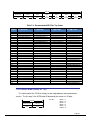
Table 3-3: Power Requirements
Parameter
Value
Supply Voltage
3.6 to 5 VDC (unregulated)
20 mA typical
16 mA typical
@ max. sample rate
Average Current Draw
@ 8 Hz sample rate
During application of
external power
Peak Current Draw
During logical power
up/down or Sync Trigger
Sleep Mode Current Draw
120 mA pk, 60 mA avg over 2 ms
100 mA pk, 60 mA avg over 4 ms
0.3 mA typical
Table 3-4: Environmental Requirements
Parameter
Value
Operating Temperature*
Storage Temperature
-40C to +85C
-40C to +85C
*To meet performance specifications, recalibration may be necessary as temperature varies.
Table 3-5: Mechanical Characteristics
Parameter
Value
Dimensions (l x w x h)
Weight
Mounting Options
Connector
3.5 x 4.3 x 1.3 cm
7 gm
Screw mounts/Standoffs, horizontal or vertical
9-pin Molex, mates with pn 51146-0900
DOC#1014688 r01
Page 4
深圳市铭之光电子技术有限公司 全国服务热线 : 400-883-3391
http://www.sensorexpert.com.cn
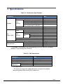
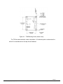
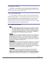
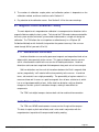
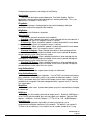
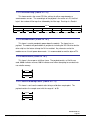
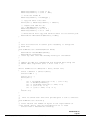
The default orientation for the TCM is for the silk-screened arrow to point in the “forward” direction.
Figure 3-1: TCM Mechanical Drawing
Figure 3-2: PNI Pigtailed Cable Drawing
Page 5
深圳市铭之光电子技术有限公司 全国服务热线 : 400-883-3391
http://www.sensorexpert.com.cn
4 Set-Up
This section describes how to configure, program, and control the TCM in your host system.
To install the TCM into your system, follow these steps:
•
•
•
•
•
Make electrical connections to the TCM
Evaluate the TCM using the included TCM Studio Program
Choose a mounting location
Mechanically mount the TCM
Perform user calibration
Before you install the module, it can be evaluated with the TCM Studio outside of your
system. Please see Section 5.
4.1 Electrical Connections
Two optional electrical cables are available to mate the TCM to a user’s host system or a
PC: a 45 cm (18”) custom pigtailed cable and a 1.8 m (6’) custom dual-connectorized cable.
Both include a Molex 51146-0900 connector on one end that mates to the TCM. The dualconnectorized cable includes a 9-pin sub-D connector on the other end to mate with a PC’s
serial port. This cable primarily is intended for basic evaluation of the TCM with a PC. The
pigtailed cable has 9 wires accessible at the end opposite from the Molex connector, and is
intended to mate with the user’s host system. The Evaluation Kit includes one of each
cable, while the Interface Kit includes just the pigtailed cable. Users also may supply their
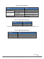
own cable. The pin-out of the pigtailed cable and Molex connector is given in Table 4-1.
Pin 1 is indicated in Figure 3-1.
DOC#1014688 r01
Page 6
深圳市铭之光电子技术有限公司 全国服务热线 : 400-883-3391
http://www.sensorexpert.com.cn
Table 4-1: TCM Pin Descriptions
Pin Description
Molex Connector
Pin Number
Pigtailed Cable
Wire Color
1
2
3
4
5
6
7
8
9
Black
Gray
Green
Orange
Violet
Brown
Yellow
Blue
Red
GND
GND
GND
NC
NC
NC
RS232 TxD
RS232 RxD
+5 VDC
4.2 Installation Location
The TCM’s wide dynamic range and sophisticated calibration algorithms allow it to
operate in many environments. For optimal performance however, you should mount the
TCM with the following considerations in mind:
4.2.1 Operate within sensors’ linear regime
The TCM can be field calibrated to correct for large static magnetic fields created by
the host system. However, each axis of the TCM has a maximum calibrated dynamic
range of ±125 µT: if the total field exceeds this value for any axis, the TCM may not give
accurate heading information. When mounting the TCM, consider the effect of any
sources of magnetic fields in the host environment that, when added to the earth’s field,
may take the sensors out of their linear regime. For example, large masses of ferrous
metals such as transformers and vehicle chassis, large electric currents, permanent
magnets such as electric motors, and so on.
4.2.2 Locate away from changing magnetic fields
It is not possible to calibrate for changing magnetic anomalies. Thus, for greatest
accuracy, keep the TCM away from sources of local magnetic distortion that will change
with time; such as electrical equipment that will be turned on and off, or ferrous bodies
that will move. Make sure the TCM is not mounted close to cargo or payload areas that
may be loaded with large sources of local magnetic fields.
Page 7
深圳市铭之光电子技术有限公司 全国服务热线 : 400-883-3391
http://www.sensorexpert.com.cn
4.2.3 Mount in a physically stable location
Choose a location that is isolated from excessive shock, oscillation, and vibration.
4.2.4 Preliminary testing
Testing should be performed at an early stage of development to understand and
accommodate the magnetic distortion contributors in a host system. Use the data logger
in TCM Studio, as discussed in Section 5.6, to perform the following tests.
Determine the distance range of field distortion. Place the compass in a fixed
position, then move or energize suspect components while observing the output to
determine when they are an influence.
Determine if the mounting location’s magnetic field is within the l range of the
compass. With the compass mounted, rotate and tilt the system in as many positions as
possible. While doing so, monitor the magnetometer outputs, observing if the maximum
linear range is exceeded.
4.3 Mechanical Mounting
Refer to Figure 3-1 for TCM dimensions and the orientation of the reference frame.
The TCM is factory calibrated with respect to its mounting holes, as shown below. It
must be aligned within the host system with respect to these mounting holes. Ensure any
stand-offs or screws used to mount the module are non-magnetic.
DOC#1014688 r01
Page 8
深圳市铭之光电子技术有限公司 全国服务热线 : 400-883-3391
http://www.sensorexpert.com.cn
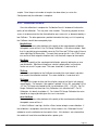
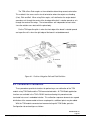
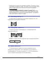
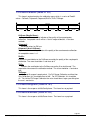
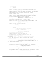
Figure 4-1: TCM Mounting Holes (bottom view)
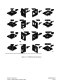
The TCM can be mounted in various orientations. All reference points are based on the
white silk-screened arrow on the top side of the board.
Page 9
深圳市铭之光电子技术有限公司 全国服务热线 : 400-883-3391
http://www.sensorexpert.com.cn
6
I /
/
(
$
$
!
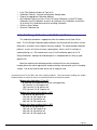
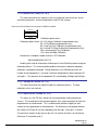
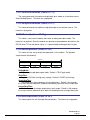
Figure 4-2: TCM Mounting Orientations
PNI Sensor Corporation
FieldForce TCM User Manual – November 2009
DOC#1014688 r01
Page 10
5 Operation with TCM Studio
The TCM Studio evaluation software communicates with the TCM through the COM port
(serial port) of your PC. It puts an easy-to-use, graphical-user interface (GUI) onto the binary
command language used by the TCM. Instead of manually issuing command codes, the user
can use buttons, check boxes, and dialog boxes to control the TCM and obtain data. It reads
the binary responses of the TCM output and formats this into labeled and easy-to-read data
fields. TCM Studio also includes the ability to log and save the outputs of the TCM to a file. All
of this allows you to begin understanding the capabilities of the TCM while using the TCM
Studio program’s friendly interface. Anything that can be performed using TCM Studio can also
be performed using the RS232 interface and associated protocol. Check the PNI website for
the latest TCM Studio updates at www.pnicorp.com.
Note: TCM Studio version 3.X is compatible with the TCM XB and TCM 6, but not other legacy TCM
models, and legacy TCM Studio programs will not function properly with the TCM XB or TCM 6. The
TCM XB model is the current version TCM with a binary communication protocol. When you launch TCM
Studio, it should say “TCM Studio Ver. 3.X” in the upper left corner, where “X” is integer “0” for greater.
5.1 Installation onto a Windows or Mac system
TCM Studio is provided as an executable program which can be downloaded from PNI’s
website. It will work with Windows 98, Windows ME, Windows 2000, Windows XP,
Windows Vista, and Mac OS X operating systems. Please check the PNI web page at
www.pnicorp.com for the latest version.
For Windows computers, copy the TCMStudio.msi file onto your computer. Then, open
the file and step through the Setup Wizard.
For Mac computers, copy the TCMStudio.zip file onto your computer. This will
automatically put the application in the working directory of your computer. The Quesa plugin, also in the .zip file, needs to be moved to: /Library/CFMSupport, if it is not already there.
Page 11
深圳市铭之光电子技术有限公司 全国服务热线 : 400-883-3391
http://www.sensorexpert.com.cn
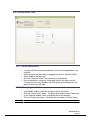
5.2 Connection Tab
5.2.1 Initial connection
•
•
•
•
•
If using the PNI dual-connectorized cable, ensure well-charged batteries are
installed.
Select the serial port the module is plugged into, which is generally COM 1.
Select 38400 as the baud rate.
Click the <Connect> button if the connection is not automatic.
Once a connection is made the “Connected” light will turn green and the
Firmware Version, Serial Number, and PCA version will be displayed in the
upper left next to the PNI logo.
5.2.2 Changing baud rate
•
•
•
•
In the Module window, select the new baud rate for the module.
Click the <Power Down> button. The button will change to read <Power Up>.
In the Computer window, select same baud rate for the computer.
Click the <Power Up> button. The button will revert back to <Power Down>.
Note: While it is possible to select a baud rate of 230400, the serial port will not operate this fast.
DOC#1014688 r01
Page 12
深圳市铭之光电子技术有限公司 全国服务热线 : 400-883-3391
http://www.sensorexpert.com.cn
5.2.3 Changing modules
Once a connection has been made, TCM Studio will recall the last settings. If a
different module is used, click the <Connect> button once the new module is attached.
This will reestablish a connection, assuming the module baud rate is unchanged.
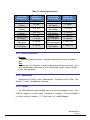
5.3 Configuration Tab
Note: No settings will be changed in the module until the <SAVE> button has been selected.
5.3.1 Mounting Options
TCM Studio supports 16 mounting orientations, as illustrated previously in Figure
4-2. The descriptions in TCM Studio are slightly different from those shown in Figure
4-2, and the relationship between the two sets of descriptions is given below.
Page 13
深圳市铭之光电子技术有限公司 全国服务热线 : 400-883-3391
http://www.sensorexpert.com.cn
Table 5-1: Mounting Orientations
TCM Studio
Description
Figure 4-2
Description
TCM Studio
Description
Figure 4-2
Description
Standard
Standard 90
Degrees
Standard 180
Degrees
Standard 270
Degrees
X Sensor Up
X Sensor Up Plus
90 Degrees
X Sensor Up Plus
180 Degrees
X Sensor Up Plus
270 Degrees
STD 0°
Y Sensor Up
Y Sensor Up Plus
90 Degrees
Y Sensor Up Plus
180 Degrees
Y Sensor Up Plus
270 Degrees
Z Sensor Down
Z Sensor Down
Plus 90 Degrees
Z Sensor Down
Plus 180 Degrees
Z Sensor Up Plus
270 Degrees
“Y” Up 0°
STD 90°
STD 180°
STD 270°
“X” Up 0°
“X” Up 90°
“X” Up 180°
“X” Up 270°
“Y” Up 90°
“Y” Up 180°
“Y” Up 270°
“Z” Down 0°
“Z” Down 90°
“Z” Down 180°
“Z” Down 270°
5.3.2 North Reference
Magnetic
When the <Magnetic> button is selected, heading will be relative to magnetic
north.
True
When the <True> button is selected, heading will be relative to true north. In this
case, the declination needs to be set in the “Declination” window. Refer to Section
6.3 for more information.
5.3.3 Endianess
Select either the <Big> or <Little> Endian button. The default setting is <Big>. See
Sections 7.2 and 7.3 for additional information.
5.3.4 Output
The TCM module can output heading, pitch, and roll in either degrees or mils. Click
either the <Degrees> or <Mils> button. The default is <Degrees>. (There are 6400 mils
in a circle, such that 1 degree = 17.7778 mils and 1 mil = 0.05625 degree.)
DOC#1014688 r01
Page 14
深圳市铭之光电子技术有限公司 全国服务热线 : 400-883-3391
http://www.sensorexpert.com.cn
5.3.5 Enable 3D Model
TCM Studio’s Test tab includes a live-action 3-D rendering of a helicopter. Some
computer systems may not have the graphics capability to render the 3D Model, for this
reason it may be necessary to turn off this feature.
5.3.6 Filter Setting (Taps)
The TCM incorporates a finite impulse response (FIR) filter to effectively provide a
more stable heading reading. The number of taps (or samples) represents the amount
of filtering to be performed. The user should select either 0, 4, 8, 16, or 32 taps, with
zero taps representing no filtering. Note that selecting a larger number of taps can
significantly slow the time for the initial sample reading and, if “Flush Filters” is selected,
the rate at which data is output. The default setting is 32.
5.3.7 Acquisition Settings
Mode
• “Poll” mode should be selected when the host system will poll the TCM for
data. TCM Studio allows the user to simulate this on their PC. In this case,
TCM Studio requests data from the TCM module at a relatively fixed basis.
• “Push” mode should be selected if the user will have the TCM output data at
a relatively fixed rate to the host system. In this case the TCM module is
pushing data out to TCM Studio at a relatively fixed rate.
Poll Delay
The Poll Delay is relevant when Poll Mode is selected, and is the time delay, in
seconds, between the completion of TCM Studio receiving one set of sampled data
and requesting the next sample set. If the time is set to “0”, then TCM Studio
requests new data as soon as the previous request has been fulfilled. Note that the
inverse of the Poll Delay is somewhat greater than the sample rate, since the Poll
Delay does not include actual acquisition time.
Interval Delay
The Interval Delay is relevant when Push Mode is selected, and is the time delay,
in seconds, between completion of the TCM module sending one set of sampled
data and the start of sending the next sample set. If the time is set to 0 then the
TCM will begin sending new data as soon as the previous data set has been sent.
Note that the inverse of the Interval Delay is somewhat greater than the sample rate,
since the Interval Delay does not include actual acquisition time.
Acquire Delay
The Acquire Delay sets the time between samples taken by the module, in
seconds. This is an internal setting that is NOT tied to the time with which the
module transmits data to TCM Studio or the host system. Generally speaking, the
Acquire Delay is either set to 0, in which case the TCM is constantly sampling or set
to equal either the Poll Delay or Interval Delay values. The advantage of running
Page 15
深圳市铭之光电子技术有限公司 全国服务热线 : 400-883-3391
http://www.sensorexpert.com.cn
with an Acquire Delay of 0 is that the FIR filter can run with a relatively high Tap
value to provide stable and timely data. The advantage of using a greater Acquire
Delay is that power consumption can be reduced, assuming the Interval or Poll Delay
are no less than the Acquire Delay.
Flush Filters
The filtering is set to only update the filter with the last sample taken, for example
once the initial 32 samples are taken (assuming Taps is set to the default value of
32) any new sample is added to the end with the first sample being dropped. In the
case where the “Acquire Time” is set to a value it would be prudent to set the module
to flush the filter prior to calculating the heading. This flushing will require the
module to take 32 new samples to use for the calculation.
Note: If the “Flush Filters” checkbox is checked, it will take longer for the module to output updated data.
5.3.8 HPR During Calibration
When the <On> button is selected, heading, pitch, and roll will be output on the
Calibration tab during a calibration.
5.3.9 Calibration Settings
Automatic Sampling
When selected the module will take a point once the minimum change
requirement and the stability check, if selected, has been satisfied. If the user wants
to have more control over when the point will be taken then Auto Sampling should be
deselected. Once deselected, the <Take Sample> button on the Calibration tab will
be active. Selecting the <Take Sample> button will indicate to the module to take a
sample once the minimum requirements are met.
Calibration Points
The user can select the number of points to take during a calibration. The
minimum number of points needed for an initial calibration is 10, although a hard-iron
only (re)calibration can be performed with only 4 samples. The module will need to
be rotated through at least 180 degrees in the horizontal plane with a minimum of at
least 1 positive and 1 negative Pitch and at least 1 positive and 1 negative Roll as
part of the 12 points.
Calibration Method Buttons
•
Full Range Calibration - recommended calibration method when >45° of tilt
is possible. The minimum recommended number of calibration points is 12.
•
Hard Iron Only Calibration - serves as a hard iron recalibration to a prior
calibration. If the hard iron distortion around the module has changed, this
calibration can bring the module back into specification. The minimum
recommended number of calibration points is 6.
DOC#1014688 r01
Page 16
深圳市铭之光电子技术有限公司 全国服务热线 : 400-883-3391
http://www.sensorexpert.com.cn
•
Limited Tilt Range Calibration - recommended calibration method when
>5° of tilt calibration is available, but tilt is restricted to <45°. (i.e. full range
calibration is not possible.) The minimum recommended number of
calibration points is 12.
•
2D Calibration - recommended when the available tilt range is limited to 5K.
The minimum recommended number of calibration points is 12.
•
Accel Calibration Only – The user should select this when accelerometer
calibration will be performed. The minimum recommended number of
calibration points is 18.
•
Accel Calibration w/Mag – The user should select this when magnetometer
and accelerometer calibration will be performed simultaneously. The
minimum recommended number of calibration points is 18.
5.3.10 Default
Clicking this button reverts TCM Studio program to the factory default settings.
5.3.11 Retrieve
Clicking on this button causes TCM Studio to read the settings from the module and
display them on the screen.
Page 17
深圳市铭之光电子技术有限公司 全国服务热线 : 400-883-3391
http://www.sensorexpert.com.cn
5.4 Calibration Tab
Note: The default settings of the module are recommended for the highest accuracy and quality of
calibration.
5.4.1 Samples
Before proceeding, refer to Section 6.2 for the recommended calibration procedure
corresponding to the calibration method selected on the Configuration tab.
Clicking the <Start> button begins the calibration process.
If “Automatic Sampling” is not checked on the Configuration tab, it is necessary to
click the <Take Sample> button to take a calibration sample point. This should be
repeated until the total number of samples (as set on the Configuration tab) is taken,
changing the orientation of the module between samples as discussed in Section 6.2.
If “Automatic Sampling” is checked, the module will need to be held steady for a
short time and then a sample automatically will be taken. Once the window indicates the
next number, the module’s orientation should be changed and held steady for the next
DOC#1014688 r01
Page 18
深圳市铭之光电子技术有限公司 全国服务热线 : 400-883-3391
http://www.sensorexpert.com.cn
sample. Once the pre-set number of samples has been taken (as set on the
Configuration tab) the calibration is complete.
5.4.2 Calibration Results
Once the calibration is complete the “Calibration Results” window will indicate the
quality of the calibration. This may take a few seconds. The primary purpose of these
scores is to demonstrate that the field calibration was successful, as demonstrated by a
low CalScore. The other parameters provide information that may assist in improving
the CalScore should it be unacceptably high.
Mag CalScore
Represents the over-riding indicator of the quality of the magnetometer calibration.
Acceptable scores will be <1 for Full Range Calibration, <2 for other methods. Note
that it is possible to get acceptable scores for Dist Error and Tilt Error and still have a
rather high Mag CalScore value. The most likely reason for this is the TCM is close
to a source of local magnetic distortion that is not fixed with respect to the module.
Dist Error
Indicates the quality of the sample point distribution, primarily looking for an even
yaw distribution. Significant clumping or a lack of sample points in a particular
section can result in a poor score. The score should be <1 and close to 0.
Tilt Error
Indicates the contribution to the CalScore caused by tilt or lack thereof, and takes
into account the calibration method. The score should be <1 and close to 0.
Tilt Range
This reports the larger of either half the full pitch range or half the full roll range of
sample points. For example, if the module is pitched +10K to -20º, and rolled +25º to
-15º, the Tilt Range value would be 20º (as derived from [+25º - {-15º}]/2). For Full
Range Calibration and Hard Iron Only Calibration, this should be 45°. For 2D
Calibration, this ideally should be 2°. For Limited Tilt Range Calibration the value
should be as large a possible given the user’s constraints.
Accel CalScore
Represents the over-riding indicator of the quality of the accelerometer calibration.
Acceptable scores will be <1.
If either CalScore is too high, click the <Start> button to begin a new calibration. If
the calibration is acceptable, then click the <Save> button in the “Calibration Results”
window to save the calibration to the module’s flash. If this button is not selected then
the module will need to be recalibrated after a power cycle.
Page 19
深圳市铭之光电子技术有限公司 全国服务热线 : 400-883-3391
http://www.sensorexpert.com.cn
Note: If a calibration is aborted, all the score’s will read “179.80”, and the calibration coefficients will not
be changed. (Clicking the <Save> button will not change the calibration coefficients either.)
5.4.3 Current Configuration
These indicators mimic the pertinent selections made on the Configuration tab.
5.4.4 Options
This window indicates how many samples are to be taken and provides real time
heading, pitch, and roll information if “HPR During Calibration” is set to <On>, both as
defined on the Configuration tab.
Audible Feedback:
If selected TCM Studio will give an audible signal once a calibration point has
been taken. Note that an audible signal also will occur when the <Start> button is
clicked, but no data will be taken.
5.4.5 Clear
Clear Mag Cal to Factory:
This button clears the user’s calibration of the magnetometers. Once selected,
the module reverts to its factory magnetometer calibration. To save this action in
nonvolatile memory, click the <Save> button. It is not necessary to clear the current
calibration in order to perform a new calibration.
Clear Accel Cal to Factory:
This button clears the user’s calibration of the accelerometers. Once selected,
the module reverts back to its factory accelerometer calibration. To save this action
in non-volatile memory, click the <Save> button. It is not necessary to clear the
current calibration in order to perform a new calibration.
DOC#1014688 r01
Page 20
深圳市铭之光电子技术有限公司 全国服务热线 : 400-883-3391
http://www.sensorexpert.com.cn
5.5 Test Tab
5.5.1 Current Reading
Once the <Go> button is selected the module will begin outputting heading, pitch
and roll information. Selecting the <Stop> button or changing tabs will halt the output of
the module.
Contrast:
Selecting this box sets the “Current Readings” window to have yellow lettering on
a black background, rather than black lettering on a white background.
5.5.2 3D Model
The helicopter will follow the movement of the TCM and give a visual representation
of the module’s orientation, assuming the “Enable 3D Model Display” box is selected on
the Configuration tab.
5.5.3 Acquisition Settings
These indicators mimic the pertinent selections made on the Configuration tab.
Page 21
深圳市铭之光电子技术有限公司 全国服务热线 : 400-883-3391
http://www.sensorexpert.com.cn
5.5.4 Sync Mode
Sync Mode enables the module to stay in sleep mode until the user’s system sends
a trigger to report data. When so triggered, the TCM will wake up, report data once,
then return to sleep mode. One application of this is to lower power consumption.
Another use of the Sync Mode is to trigger a reading during an interval when local
magnetic sources are well understood. For instance, if a system has considerable
magnetic noise due to nearby motors, the Synch Mode can be used to take
measurements when the motors are turned off.
Enter Sync Mode:
On the Test tab, above the tabs and 3D model, click the “Sync Mode” check box
to enter Sync Mode.
Sync Mode Output:
To retrieve the first reading, click the <Sync Read> button. Heading, pitch and
roll information will be displayed on Current Reading window. If the “Enable 3D
Model Display” box is selected on the Configuration tab, then the helicopter will
follow the movement as well. The module will enter sleep mode after outputting the
heading, pitch, and roll information. To obtain subsequent readings, the user should
first click on the <Sync Trigger> button to wake up the module and then click on the
<Sync Read> button to get the readings, after which the module will return to sleep.
Exit Sync Mode:
Click on the <Sync Trigger> button and then uncheck the “Sync Mode” check box
to exit Sync Mode.
Note that <Sync Trigger> sends a 0xFF signal as an external interrupt to wake up
the module. This is not done for the first reading as the module is already awake.
DOC#1014688 r01
Page 22
深圳市铭之光电子技术有限公司 全国服务热线 : 400-883-3391
http://www.sensorexpert.com.cn
5.6 Data Logger Tab
TCM Studio can capture measurement data and then export it to a text file. To acquire
data and export it, follow the procedure below:
•
•
•
•
•
Select the parameters you wish to log in the “Data” window. Use Shift-Ctrl-Click
and Ctrl-Click to select multiple items. (In the screen shot above, “Heading”, “MX
(kXAligned)”, “MY (kYAligned)”, and “MZ (kZAligned)” were selected.)
Click the <Go> button to start logging. The <Go> button changes to a <Stop>
button after data logging begins.
Click the <Stop> button to stop logging data.
Click the <Export> button to save the data to a file.
Click the <Clear> button to clear the data from the window.
Note: The data logger use ticks for time reference. A tick is 1/60 second.
Page 23
深圳市铭之光电子技术有限公司 全国服务热线 : 400-883-3391
http://www.sensorexpert.com.cn
5.7 System Log Tab
The System Log tab shows all communication between TCM Studio and the TCM
module since TCM Studio was opened. Closing TCM Studio will erase the system log.
Select the <Export> button, at the bottom right of the screen, to save the system log to a
text file.
DOC#1014688 r01
Page 24
深圳市铭之光电子技术有限公司 全国服务热线 : 400-883-3391
http://www.sensorexpert.com.cn
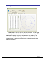
5.8 Graph Tab
The graph provides a 2-axis (X,Y) plot of the measured field strength. The graph can be
used to visually see hard and soft iron effects within the environment measured by the TCM
module as well as corrected output after a user calibration has been performed. (The
screen shot shows the MX and MY readings as the module was held horizontally and
rotated through 360º in the horizontal plane, then held in a vertical orientation and rotated
360º in the vertical plane.)
Page 25
深圳市铭之光电子技术有限公司 全国服务热线 : 400-883-3391
http://www.sensorexpert.com.cn
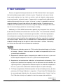
6 User Calibration
Sources of magnetic distortion positioned near the TCM will distort Earth’s local magnetic
field and should be compensated for in the host system. Examples of such sources include
ferrous metals and alloys (ex. iron, nickel, non-stainless steel, etc.), batteries, audio speakers,
current-carrying wires, and electric motors. Compensation is accomplished by calibrating the
module while mounted in the user’s system. In the user’s system it is expected the sources of
magnetic distortion will remain fixed relative to the module’s position. By performing a user
calibration, the TCM identifies the local sources of magnetic distortion and negates their effects
from the overall reading to provide an accurate compass heading.
Additionally, the TCM’s MEMS accelerometers gradually may change over time, and it may
be desirable to recalibrate the accelerometers from time-to-time. The accelerometer calibration
procedure corrects for changes in accelerometer gain and offset. Unlike the magnetometers,
the accelerometers may be calibrated outside the host system. Accelerometer calibration is
more sensitive to noise or hand jitter than magnetometer calibration, especially for subsequent
use at high tilt angles. Because of this, a stabilized fixture is recommended for accelerometer
calibration, although resting the unit against a stable surface often is sufficient. Alternatively,
the TCM can be returned to PNI for accelerometer recalibration.
Key Points
1. Accelerometer calibration requires the TCM essentially be rotated through a full sphere
of coverage. However, it does not require the module be incorporated into the user’s
system during the calibration.
2. Magnetometer calibration requires incorporating the module into the user’s system such
that the magnetic components of the user’s system can be compensated for.
3. Magnetometer and accelerometer calibrations can be performed simultaneously. But it
may be easier to perform them separately since the requirements of each calibration are
significantly different. (Magnetometer calibration requires the module be incorporated in
the user’s system, while accelerometer calibration requires full sphere coverage.)
4. Full Range (magnetometer) Calibration provides the highest heading accuracy, but often
performing a Full Range Calibration is not practical. 2D and Limited Tilt Calibration allow
for reasonably good calibration when the range of allowable motion is limited. Hard Iron
Only Calibration relatively easily updates the hard-iron compensation coefficients.
DOC#1014688 r01
Page 26
深圳市铭之光电子技术有限公司 全国服务热线 : 400-883-3391
http://www.sensorexpert.com.cn
5. The number of calibration sample points and calibration pattern is dependent on the
calibration method, and these are discussed in Section 6.2.
6. Pay attention to the calibration scores. See Section 5.4.2 for the score meanings.
6.1 Magnetic Field Calibration Theory
The main objective of a magnetometer calibration is to compensate for distortions to the
magnetic field caused by the host system. To that end the TCM needs to be mounted within
the host system and the entire host system needs to be moved as a single unit during the
calibration. The TCM allows the user to perform a calibration only in a 2D plane (2D
Calibration Method) or with limited tilt, but provides the greatest accuracy if the user can
rotate through 360K of yaw and ±45K of tilt,
6.1.1 Hard and Soft Iron Effects
Hard iron distortions are caused by permanent magnets and magnetized steel or iron
objects within close proximity to the sensors. This type of distortion remains constant
and in a fixed location relative to the sensors for all heading orientations. Hard-iron
distortions add a constant magnitude field component along each axis of sensor output.
Soft-iron distortions are the result of interactions between the Earth’s magnetic field
and any magnetically “soft” material within close proximity to the sensors. In technical
terms, soft materials have a high permeability. The permeability of a given material is a
measure of how well it serves as a path for magnetic lines of force, relative to air, which
has an assigned permeability of one. Unlike hard-iron distortion, soft-iron distortion
changes as the host system’s orientation changes, making it more difficult to
compensate.
The TCM 3-axis digital compass features both soft-iron and hard-iron correction.
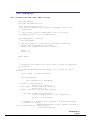
6.1.2 Pitch and Roll
The TCM uses MEMS accelerometers to measure the tilt angle of the compass.
This data is output as pitch and roll data, and is also used in conjunction with the
magnetometers to provide a tilt-compensated heading reading.
Page 27
深圳市铭之光电子技术有限公司 全国服务热线 : 400-883-3391
http://www.sensorexpert.com.cn
The TCM utilizes Euler angles as the method for determining accurate orientation.
This method is the same used in aircraft orientation where the outputs are Heading
(Yaw), Pitch and Roll. When using Euler angles, roll is defined as the angle rotated
around an axis through the center of the fuselage while pitch is rotation around an axis
through the center of the wings. These two rotations are independent of each other
since the rotation axes rotate with the plane body.
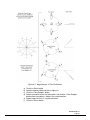
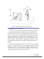
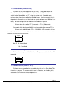
For the TCM a positive pitch is when the front edge of the board is rotated upward
and a positive roll is when the right edge of the board is rotated downward.
Figure 6-1: Positive & Negative Roll and Pitch Definition
6.2 Calibration Procedures
These procedures provide instructions for performing a user calibration of the TCM
module using TCM Studio and the TCM connectorized cable. All TCM Studio application
functions are available in the TCM’s RS232 interface allowing this procedure to be
translated into a user’s embedded solution. This calibration sequence demonstrates a good
distribution of the recommended minimum sample points, additional points may be added.
With the TCM module connected and communicating with TCM Studio, go to the
Configuration tab and configure as follows:
DOC#1014688 r01
Page 28
深圳市铭之光电子技术有限公司 全国服务热线 : 400-883-3391
http://www.sensorexpert.com.cn
•
•
•
•
•
•
In the Filter Settings window set Taps to 32
Calibration Settings: Uncheck the Automatic Sampling box
Choose the appropriate Calibration Method
Set Calibration Points to at least 12 for Full Range Calibration, Limited Tilt Range
Calibration and 2D Calibration; at least 6 for Hard Iron Only Calibration; and at least
18 for Accel Only Calibration and Accel and Mag Calibration.
Click the <Save> button.
Go to the Calibration tab.
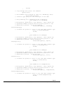
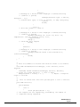
6.2.1 Full Range Calibration with 12 Sample Points
This calibration procedure is appropriate when the module can be tilted ±45K or
more. The Full Range Calibration option calibrates out hard and soft iron effects in three
dimensions, and allows for the highest accuracy readings. The recommended calibration
pattern is a series of 3 circles of evenly spaced points, with as much tilt variation as
expected during use. PNI recommends using 12 to 32 calibration points for a Full
Range Calibration, although 10 calibration points is acceptable but less likely to yield
good results.
Move the module to the following positions noting that these are not absolute
heading directs but rather approximate heading changes referenced to your first heading
sample. You do not need to know actual true or magnetic north.
Note: Once you begin taking calibration points, pausing between desired calibration points will cause
unintentional points to be taken with auto sampling enabled. PNI recommends enabling the audible
feedback feature to reduce the chance of unknowingly taking unintentional samples.
Module with slight pitch (-5 to +5 )
0° yaw with 10K-20K positive roll (initial starting position)
90° yaw with 10K-20K negative roll
180° yaw with 10K-20K positive roll
270° yaw with 10K-20K negative roll
Module with large positive pitch (>+45 )
30° with 10K-20K positive roll
120° with 10K-20K negative roll
210° with 10K-20K positive roll
300° with 10K-20K negative roll
Module with large negative pitch (<-45°)
60° with 10K-20K positive roll
150° with 10K-20K negative roll
240° with 10K-20K positive roll
330° with 10K-20K negative roll.
Page 29
深圳市铭之光电子技术有限公司 全国服务热线 : 400-883-3391
http://www.sensorexpert.com.cn
Figure 6-2: Magnetometer 12 Point Calibration
a)
b)
c)
d)
Click the <Start> button
Hold the module stable and with a slight (
.
Click the <Take Sample> button
Rotate the module to the next orientation, and click the <Take Sample>
button when the module is stable in the new orientation.
e) Repeat step d until all 12 samples are taken.
f) Click the <Save> button
DOC#1014688 r01
Page 30
深圳市铭之光电子技术有限公司 全国服务热线 : 400-883-3391
http://www.sensorexpert.com.cn
The Calibration Results window in TCM Studio displays the CalScore, which should
be 1. If it is not, check the Dist Error and Tilt Error values to see if either is >1. If the
Dist Error is >1, this indicates the calibration sample set wasn’t evenly distributed and
another calibration should be performed with this in mind. If the Tilt Error value is >1,
this indicates the calibration sample’s tilt range was not sufficient: confirm this by
looking at the Tilt Range value.
6.2.2 2D Calibration with 12 Calibration Points
This calibration procedure is used for very low tilt operation (< 5K) where calibrating
the module with higher tilts is not practical.
The 2D Calibration method calibrates out hard and soft iron effects in two
dimensions only, and in general is effective for operation and calibration in the tilt range
of -5K to 5K. The recommended calibration pattern is a circle of evenly spaced points.
Results will be optimized if the tilt in the calibration procedure can match the actual tilt
experienced when in service. (For example, if the TCM will be restrained to a level
plane in service, this means the best results will be obtained if the calibration is
exclusively in a plane, where “maximum…tilt” below would be 0K.) PNI recommends 12
to 32 calibration points for 2D Calibration, although 10 calibration points is acceptable
but less likely to yield good results.
0° yaw with no tilt
30° yaw with maximum negative tilt (pitch and roll)
60° yaw with no tilt
90° yaw with maximum positive tilt (pitch and roll)
120° yaw with no tilt
150° yaw with maximum negative tilt (pitch and roll)
180° yaw with no tilt
210° yaw with maximum positive tilt (pitch and roll)
240° yaw with no tilt
270° yaw with maximum negative tilt (pitch and roll)
300° yaw with no tilt
330° yaw with maximum positive tilt (pitch and roll)
6.2.3 Hard Iron Only Calibration with 6 Calibration Points
Over time the magnetic distortions around the TCM may change for a variety of
reasons. The Hard Iron Only Calibration method allows the user to quickly recalibrate
Page 31
深圳市铭之光电子技术有限公司 全国服务热线 : 400-883-3391
http://www.sensorexpert.com.cn
the module for hard iron effects in three-dimensions, and generally is effective for
operation and calibration in the tilt range of 3° or more (45° or more is suggested). The
recommended calibration pattern is a circle of alternate tilted, evenly spaced points, with
as much tilt variation as expected during use. PNI recommends at least 6 calibration
points for a Hard Iron Only Calibration, although 4 calibration points is acceptable but
less likely to yield good results.
0° yaw with -45K tilt (pitch and roll)
60° yaw with +45K tilt (pitch and roll)
120° yaw with -45K tilt (pitch and roll)
180° yaw with +45K tilt (pitch and roll)
240° yaw with -45K tilt (pitch and roll)
300° yaw with +45K tilt (pitch and roll)
6.2.4 Limited Tilt Range Calibration with 12 Calibration Points
This procedure is recommended when 45K of tilt isn’t feasible, but >5° of tilt is
possible. It provides both hard iron and soft iron distortion correction. The
recommended calibration pattern is a series of 3 circles of evenly spaced points, with as
much tilt variation as expected during use. PNI recommends 12 to 32 calibration points
for a Limited Tilt Range Calibration, although 10 calibration points is acceptable but less
likely to yield good results.
Module approximately level
0° yaw
90° yaw
180° yaw
270° yaw
Module with at least +5 of tilt (pitch or roll) - more tilt is better
45° yaw
135° yaw
225° yaw
315° yaw
Module with at least -5 of tilt (pitch or roll) - more tilt is better
45° yaw
135° yaw
225° yaw
315° yaw
Note that a similar and acceptable alternative pattern would be to follow the
recommended 12 point Full Range Calibration pattern, but substituting the >±45K of pitch
DOC#1014688 r01
Page 32
深圳市铭之光电子技术有限公司 全国服务热线 : 400-883-3391
http://www.sensorexpert.com.cn
with whatever pitch can be achieved and the ±10° to ±20° or roll with whatever roll can
be achieved up to these limits. (See Section 6.2.1)
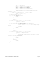
6.2.5 Accelerometer Only Calibration with 18 Calibration Points
The requirements for a good accelerometer calibration differ from the requirements
for a good magnetometer calibration. For instance, a level yaw sweep, no matter how
many points are acquired, is effectively only 1 accelerometer calibration point. PNI
recommends 18-32 calibration points for accelerometer calibration, although 12
calibration points is acceptable but less likely to yield good results..
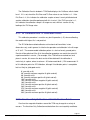
Figure 6-3 shows the two basic starting positions for the Accelerometer Only
Calibration. Calibration can occur within the user’s system or with the module alone. It
is not necessary for the module to be placed on a hard surface as shown, but the
module must be held still during calibration, and holding it against a hard surface is one
method to help ensure this.
Starting with the module as shown on the left in Figure 6-3, rotate the module such
that it sits on each of its 6 faces. Take a calibration point on each face.
Starting with the module as shown on the left, rotate it 45° such that it is standing on
one of its corners, as shown for the module on the right. The picture shows the module
also rotated about its Z axis, but this is only for illustration purposes. Take a calibration
point (0°). Now tilt the module back 45° and take another calibration point (+45°), then tilt
the module forward 45° and take another calibration point (-45°). Repeat this 3 point
calibration process for the module with it resting on each of its 4 corners.
Note that the calibration points can be obtained in any order.
Page 33
深圳市铭之光电子技术有限公司 全国服务热线 : 400-883-3391
http://www.sensorexpert.com.cn
Figure 6-3: Accelerometer Calibration Starting Orientations
6.2.6 Mag and Accel Calibration
The TCM allows for a simultaneous magnetometer and accelerometer calibration.
This requires a good calibration pattern, stable measurements (not handheld), and
installation in the user’s system such that the appropriate local magnetic environment is
present. PNI recommends 18 to 32 calibration points for a Mag and Accel Calibration,
although 12 calibration points is acceptable but less likely to yield good results. The
Accelerometer Only Calibration pattern discussed in Section 6.2.5 will work for a Mag
and Accel Calibration. Optimal performance is obtained when all rotations of the cube
are performed towards magnetic north to achieve the widest possible magnetic field
distribution.
Note that combining calibrations only makes sense if all the host system’s magnetic
distortions (steel structures or batteries, for instance) are present and fixed relative to the
module when calibrating. If the Accelerometer Only Calibration is performed, the user’s
system distortions are not relevant, which allows the TCM to be removed from the host
system in order to perform the Accelerometer Only Calibration.
DOC#1014688 r01
Page 34
深圳市铭之光电子技术有限公司 全国服务热线 : 400-883-3391
http://www.sensorexpert.com.cn
6.3 Declination Value
Declination, also called magnetic variation, is the difference between true and magnetic
north, relative to a point on the earth. It is measured in degrees east or west of true north.
Correcting for declination is accomplished by storing the correct declination angle, and then
changing the heading reference from magnetic north to true north. Declination angles vary
throughout the world, and change very slowly over time. For the greatest possible accuracy,
go to the National Geophysical Data Center web page below to get the declination angle
based on your latitude and longitude:
http://www.ngdc.noaa.gov/geomagmodels/Declination.jsp
6.4 Other Limitations
The TCM measures the total magnetic field within its vicinity, and this is a combination of
the earth’s magnetic field and local magnetic sources. The module can compensate for
local static magnetic sources that do not exceed the dynamic range of its magnetometers.
A magnetic source which is not static can create errors, and it is not possible to compensate
for such a dynamic nature. In such cases, moving the TCM away from dynamic magnetic
fields is recommended.
Page 35
深圳市铭之光电子技术有限公司 全国服务热线 : 400-883-3391
http://www.sensorexpert.com.cn
7 Operation with RS232 Interface
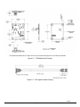
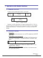
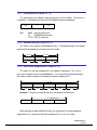
7.1 Datagram Structure
The data structure for RS232 communication is shown below:
ByteCount
(UInt16)
Packet Frame
(1 - 4092 UInt8)
Frame
ID
(UInt8)
CRC-16
(UInt16)
Payload
(1 - 4091 UInt8)
Figure 7-1: Datagram Structure
ByteCount is the total number of bytes in the packet including the CRC-16. CRC-16 is
calculated starting from the ByteCount to the last byte of the Packet Frame (see included C
function at end of document). The ByteCount and CRC-16 are always transmitted in BIG
ENDIAN.
7.2 Parameter Formats
Floating Point
The floating-point based parameters are in the IEEE standard format, ANSI/IEEE
Std 754-1985.
64-Bit (double precision floating point)
Shown below is the 64-bit float format in big Endian, in little Endian bytes are in
reverse order in 4 byte groups (i.e.: big Endian: ABCDEFGH little Endian: DCBA
HGFE).
63 62
S
5251
Exponent
0
Mantissa
The value (v) is determined as (if and only if 0 < Exponent < 2047): v = (-1)S *
2(Exponent-1023) * 1.Mantissa
32-Bit (single precision floating point)
Shown below is the 32-bit float format in big Endian, in little Endian all 4 bytes
are in reverse order (LSB first).
DOC#1014688 r01
Page 36
深圳市铭之光电子技术有限公司 全国服务热线 : 400-883-3391
http://www.sensorexpert.com.cn
3130
S
2322
0
Exponent
Mantissa
The value (v) is determined as (if and only if 0 < Exponent < 255): v = (-1)S *
2(Exponent-127) * 1.Mantissa
Note: Please refer to ANSI/IEEE Std 754-1985 for more information. It is also recommended that you
refer to the compiler you are using on how it implements floating-point formats.
Signed 32-bit Integer (SInt32)
SInt32 based parameters are signed 32 bit numbers (2’s compliment). Bit 31
represents the sign of the value (0=positive, 1=negative)
31
24 23
16 15
8 7
msb
0
lsb
Big Endian
7
0 15
8 23
16 31
lsb
24
msb
Little Endian
Signed 16-bit Integer (SInt16)
SInt16 based parameters are signed 16 bit numbers (2’s compliment). Bit 15
represents the sign of the value (0=positive, 1=negative)
15
8 7
msb
0
lsb
Big Endian
7
0 15
lsb
8
msb
Little Endian
Signed 8-bit Integer (SInt8)
UInt8 based parameters are unsigned 8-bit numbers. Bit 7 represents the sign of
the value (0=positive, 1=negative)
7
0
byte
Page 37
深圳市铭之光电子技术有限公司 全国服务热线 : 400-883-3391
http://www.sensorexpert.com.cn
Unsigned 32-bit Integer (UInt32)
UInt32 based parameters are unsigned 32 bit numbers.
31
24 23
16 15
8 7
msb
0
lsb
Big Endian
7
0 15
8 23
16 31
lsb
24
msb
Little Endian
Unsigned 16-bit Integer (UInt16)
UInt16 based parameters are unsigned 16 bit numbers.
15
8 7
msb
0
lsb
Big Endian
7
0 15
lsb
8
msb
Little Endian
Unsigned 8-bit Integer (UInt8)
UInt8 based parameters are unsigned 8-bit numbers.
7
0
byte
Boolean
Boolean is a 1-byte parameter that MUST have the value 0 (FALSE) or 1
(TRUE).
7
0
byte
DOC#1014688 r01
Page 38
深圳市铭之光电子技术有限公司 全国服务热线 : 400-883-3391
http://www.sensorexpert.com.cn
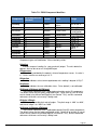
7.3 Commands & Communication Frames
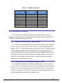
Table 7-1: RS232 Command Set
Frame
Command
ID
1
2
3
4
5
6
7
8
9
10
11
kGetModInfo
kModInfoResp
kSetDataComponents
kGetData
kDataResp
kSetConfig
kGetConfig
kConfigResp
kSave
kStartCal
kStopCal
12
kSetParam
13
kGetParam
14
kParamResp
15
16
17
18
19
20
21
22
23
24
25
26
27
28
29
30
kPowerDown
kSaveDone
kUserCalSampCount
kUserCalScore
kSetConfigDone
kSetParamDone
kStartIntervalMode
kStopIntervalMode
kPowerUp
kSetAcqParams
kGetAcqParams
kAcqParamsDone
kAcqParamsResp
kPowerDownDone
kFactoryUserCal
kFactorUserCalDone
31
kTakeUserCalSample
36
37
46
47
48
kFactoryInclCal
kFactoryInclCalDone
kSetMode
kSetModeResp
kSyncRead
Description
Queries the modules type and firmware revision number.
Response to kGetModInfo
Sets the data components to be output.
Queries the module for data
Response to kGetData
Sets internal configurations in the module
Queries the module for the current internal configuration value
Response to kGetConfig
Commands the module to save internal and user calibration
Commands the module to start user calibration
Commands the module to stop user calibration
Sets the FIR filter settings for the magnetometer &
accelerometer sensors.
Queries for the FIR filter settings for the magnetometer &
accelerometer sensors.
Contains the FIR filter settings for the magnetometer &
accelerometer sensors.
Used to completely power-down the module
Response to kSave
Sent from the module after taking a calibration sample point
Contains the calibration score
Response to kSetConfig
Response to kSetParam
Commands the module to output data at a fixed interval
Commands the module to stop data output at a fixed interval
Sent after wake up from power down mode
Sets the sensor acquisition parameters
Queries for the sensor acquisition parameters
Response to kSetAcqParams
Response to kGetAcqParams
Response to kPowerDown
Clears user magnetometer calibration coefficients
Response to kFactoryUserCal
Commands the module to take a sample during user
calibration
Clears user accelerometer calibration coefficients
Respond to kFactoryInclCal
Sets the mode of operation of the system
Response to kSetMode
Queries the module for data in Sync Mode
Page 39
深圳市铭之光电子技术有限公司 全国服务热线 : 400-883-3391
http://www.sensorexpert.com.cn
7.3.1 kGetModInfo (frame ID 1 d)
This frame queries the module'
s type and firmware revision number. The frame has
no payload. The complete packet for the kGetModInfo command would be:
0005
01
With:
EFD4
0005 being the byte count
01
kGetModInfo command
EFD4 CRC-16 checksum
7.3.2 kModInfoResp (frame ID 2 d)
This frame is the response to kGetModInfo frame. The payload contains the module
type identifier followed by the firmware revision number.
Frame ID
Payload
2
Type
Revision
kUlnt8
UInt32
UInt32
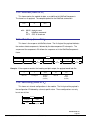
7.3.3 kSetDataComponents (frame ID 3 d)
This frame sets the data components in the module'
s data output. This is not a
query for the module'
s data (see kGetModInfo). The first byte of the payload indicates
the number of data components followed by the data component IDs.
Payload
Count
ID1
ID2
ID3
IDCount
UInt8
UInt8
UInt8
UInt8
UInt8
Example: To query the heading and pitch, the payload should contain
Payload
3
2
5
24
Frame ID
ID Count
Heading ID
Pitch ID
When querying for data (kGetData frame), the sequence of the data component
output follows the sequence of the data component IDs as set in this frame.
DOC#1014688 r01
Page 40
深圳市铭之光电子技术有限公司 全国服务热线 : 400-883-3391
http://www.sensorexpert.com.cn
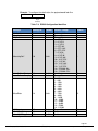
Table 7-2: RS232 Component Identifiers
Component
DataComponentID
(decimal)
Format
kHeading
5
Float32
kTemperature 7
Float32
degrees (default)
or mils
˚ Celsius
kDistortion
8
Boolean
True or False
kCalStatus
9
Boolean
True or False
kPAligned
KRAligned
kIZAligned
kPAngle
21
22
23
24
Float32
Float32
Float32
Float32
G
G
G
degrees
kRAngle
25
Float32
degrees
KXAligned
KYAligned
KZAligned
27
28
29
Float32
Float32
Float32
µT
µT
µT
Units
Range
0.0˚ to 359.9˚
-40˚ to 85˚
False (Default)
= no distortion
False (Default)
= not calibrated
-1.0 to 1.0
-1.0 to 1.0
-1.0 to 1.0
-90.0˚ to 90.0˚
-180.0˚ to
180.0˚
Component types are listed below. All are read-only values.
kHeading
Provides compass heading (i.e. yaw or azimuth) output. The units default to
degrees, but can be set to mils using kMilOutput
kTemperature
This value is provided by the module’s internal temperature sensor. Its value is
in ° Celsius and has an accuracy of ±3° C.
kDistortion
This flag indicates at least one magnetometer axis reading is beyond ±125 µT.
kCalStatus
This flag indicates the user calibration status. False (default) = not calibrated.
kPAligned, kRAligned & kIZAligned
These values represent Earth’s calibrated acceleration vector (G) components.
The default values are the factory calibrated values. Up to three (3) sets of values
can be stored using kAccelCoeffCopySet (see Section 7.3.6), and this command
references whichever set currently is being used.
kPAngle, kRAngle
These outputs provide pitch and roll angles. The pitch range is -90.0˚ to +90.0˚,
and the roll range is to -180.0˚ to +180.0˚.
kXAligned, kYAligned, kZAligned
These values represent Earth’s calibrated magnetic field (M) vector components.
The default values are the factory-calibrated values. Note that up to eight (8) sets of
values can be stored using kCoeffCopySet (see Section 7.3.6), and this command
references whichever set currently is being used.
Page 41
深圳市铭之光电子技术有限公司 全国服务热线 : 400-883-3391
http://www.sensorexpert.com.cn
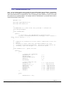
7.3.4 kGetData (frame ID 4 d)
This frame queries the module for data, as established in kSetDataComponents.
The frame has no payload. The complete packet for the kGetData command is:
00 05
04
with:
BF71
00 05 the byte count
04
kGetData command
BF71 CRC-16 checksum
7.3.5 kDataResp (frame ID 5 d)
This frame is the response to kGetData frame. The first byte of the payload indicates
the number of data components, followed by the data component ID-value pairs. The
sequence of the components IDs follows the sequence set in the kSetDataComponents
frame.
Payload
Count
ID1
ValueID1
ID2
ValueID2
IDCount
ValueIDCount
UInt8
UInt8
ID
Specific
UInt8
ID
Specific
UInt8
ID
Specific
Example: If the response contains the heading and pitch output, the payload would look like
2
5
359.9
24
10.5
ID Count
Heading ID
Heading
Output
(Float32)
Pitch ID
Pitch
Output
(Float32)
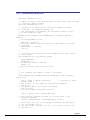
7.3.6 kSetConfig (frame ID 6 d)
This frame sets internal configurations in the module. The first byte of the payload is
the configuration ID followed by a format specific value. These configurations can only
be set one at time.
Payload
Config ID
Value
UInt8
ID
Specific
DOC#1014688 r01
Page 42
深圳市铭之光电子技术有限公司 全国服务热线 : 400-883-3391
http://www.sensorexpert.com.cn
Example: To configure the declination, the payload would look like:
1
10.0
Declination ID
Declination
Angle
(Float32)
Table 7-3: RS232 Configuration Identifiers
Settings
Config. ID
Format
Values / Range
Default
kDeclination
kTrueNorth
kBigEndian
1
2
6
Float32
Boolean
Boolean
0˚
False
True
kMountingRef*
10
UInt8
-180˚ to +180˚
True or False
True or False
1 = STD 0K
2 = X UP 0K
3 = Y UP 0K
4 = STD 90K
5 = STD 180K
6 = STD 270K
7 = Z UP 0K
8 = X UP 90°
9 = X UP 180°
10 = X UP 270°
11 = Y UP 90°
12 = Y UP 180°
13 = Y UP 270°
14 = Z DOWN 90°
15 = Z DOWN 180°
16 = Z DOWN 270°
4 – 32
True or False
0 – 300
1 – 600
2 – 1200
3 – 1800
4 – 2400
5 – 3600
6 – 4800
7 – 7200
8 – 9600
9 – 14400
10 – 19200
11 – 28800
12 – 38400
13 – 57600
14 - 115200
True or False
0-7
0-2
kUserCalNumPoints
12
kUserCalAutoSampling 13
UInt32
Boolean
kBaudRate
14
UInt8
kMilOutput
kCoeffCopySet
kAccelCoeffCopySet
15
18
19
Boolean
UInt32
UInt32
1
12
True
12
False
0
0
*Refer to Figure 4-2 for additional information on mounting orientations.
Page 43
深圳市铭之光电子技术有限公司 全国服务热线 : 400-883-3391
http://www.sensorexpert.com.cn
Configuration parameters and settings for kSetConfig:
kDeclination
This sets the declination angle to determine True North heading. Positive
declination is easterly declination and negative is westerly declination. This is not
applied until kTrueNorth is set to TRUE.
kTrueNorth
Flag to set compass heading output to true north heading by adding the
declination angle to the magnetic north heading.
kBigEndian
Flag to set the Endianness of packets
kMountingRef
This sets the reference orientation for the module:
Standard: When selected the module is to be mounted with the main board in a
horizontal position (the Z axis magnetic sensor is vertical).
X Sensor Up: When selected the module is to be mounted with the main board
in a vertical position (the X axis magnetic sensor is vertical).
Y Sensor Up: When selected the module is to be mounted with the main board
in a vertical position (the Y axis magnetic sensor is vertical).
Standard 90 Degrees: When selected the module is to be mounted with the
main board in a horizontal position but rotated so the arrow is pointed 90 degrees
counterclockwise to the front of the host system.
Standard 180 Degrees: When selected the module is to be mounted with the
main board in a horizontal position but rotated so the arrow is pointed 180 degrees
counterclockwise to the front of the host system.
Standard 270 Degrees: When selected the module is to be mounted with the
main board in a horizontal position but rotated so the arrow is pointed 270 degrees
counterclockwise to the front of the host system.
kUserCalNumPoints
The maximum number samples taken during user calibration.
kUserCalAutoSampling
This flag is used during user calibration. If set to TRUE, the module continuously
takes calibration sample points until the set number of calibration samples. If set to
FALSE, the module waits for kTakeUserCalSample frame to take a sample with the
condition that a magnetic field vector component delta is greater than 5 µT from the
last sample point.
kBaudRate
Baud rate index value. A power-down power-up cycle is required when changing
the baud rate.
kMilOutput
This flag sets the heading, pitch and roll output to mils. By default, kMilOutput is
set to FALSE and the heading, pitch and roll output are in degrees. Note that 360
degrees = 6400 mils, such that 1 degree = 17.778 mils or 1 mil = 0.05625 degree.
kCoeffCopySet
This command provides the flexibility to store up to eight (8) sets of
magnetometer calibration coefficients in the module. The default is set number 0.
To store a set of coefficients, first establish the set number (number 0 to 7) using
DOC#1014688 r01
Page 44
深圳市铭之光电子技术有限公司 全国服务热线 : 400-883-3391
http://www.sensorexpert.com.cn
kCoeffCopySet, then perform the magnetometer calibration. The coefficient values
will be stored in the defined set number. This feature is useful if the compass will be
placed in multiple locations that have different local magnetic field properties.
kAccelCoeffCopySet
This command provides the flexibility to store up to three (3) sets of
accelerometer calibration coefficients in the module. The default is set number 0.
To store a set of coefficients, first establish the set number (number 0 to 2) using
kAccelCoeffCopySet, then perform the accelerometer calibration. The coefficient
values will be stored in the defined set number.
7.3.7 kGetConfig (frame ID 7 d)
This frame queries the module for the current internal configuration value. The
payload contains the configuration ID requested.
Payload
Config ID
UInt8
7.3.8 kConfigResp (frame ID 8 d)
This frame is the response to kGetConfig frame. The payload contains the
configuration ID and value.
Payload
Config ID
Value
UInt8
ID
Specific
Example: If a request to get the set declination angle, the payload would look like:
1
10.0
Declination ID
Declination
Angle
(Float32)
7.3.9 kSave (frame ID 9 d)
This frame commands the module to save internal configurations and user
calibration to non-volatile memory. Internal configurations and user calibration is
restored on power up. The frame has no payload. This is the ONLY command that
causes the module to save information into non-volatile memory.
Page 45
深圳市铭之光电子技术有限公司 全国服务热线 : 400-883-3391
http://www.sensorexpert.com.cn
7.3.10 kStartCal (frame ID 10 d)
This frame commands the module to start user calibration with the current sensor
acquisition parameters, internal configurations and FIR filter settings.
Note: The payload needs to be 32 bit (4 byte). If no payload is entered or if less than 4 bytes are
entered, the unit will default to the previous calibration method.
Payload
C al O ption
UInt32
Calibration option values:
Calibration option values: 10 = Full Range Calibration (magnetometer only)
20 = 2D Calibration (magnetometer only)
30 = Hard Iron Only Calibration (magnetometer only)
40 = Limited Tilt Range Calibration (magnetometer only)
100 = Accelerometer Only Calibration
110 = Accel and Mag Calibration
Example for a complete sample frame for a 2D Calibration:
00 09 0A 00 00 00 14 5C F9
Heading, pitch and roll information will be output via the kDataResp frame during the
calibration process. This feature provides guidance during the calibration regarding
calibration sample point coverage. During calibration, in the kDataResp frame, the
number of data components is set to be 3 and then followed by the data component IDvalue pairs. The sequence of the component IDs are kHeading, kPAngle and kRAngle.
7.3.11 kStopCal (frame ID 11 d)
This frame commands the module to abort the calibration process. The prior
calibration results are retained.
7.3.12 kSetParam (frame ID 12 d)
This frame sets the FIR filter settings for the magnetometer and accelerometer
sensors. The second byte of the payload indicates the x vector component of either the
magnetometer or accelerometer. This is to differentiate whether to apply the filter
settings to the magnetometer or accelerometer. The third byte in the payload indicates
the number of FIR taps to use then followed by the filter taps. Each tap is a Float64.
The maximum number of taps that can be set is 32 and the minimum is 0 (no filtering).
Parameter ID should be set to 3.
DOC#1014688 r01
Page 46
深圳市铭之光电子技术有限公司 全国服务热线 : 400-883-3391
http://www.sensorexpert.com.cn
Payload
Parameter ID
Axis ID
Count
Value1
Value2
Value3
ValueCount
UInt8
UInt8
UInt8
ID
Specific
ID
Specific
ID
Specific
ID
Specific
Table 7-4: Recommended FIR Filter Tap Values
Count 4 Tap Filter
8 Tap Filter
16 Tap Filter
32 Tap Filter
1
2
3
4
5
6
7
8
9
10
11
12
13
14
15
16
17
18
19
20
21
22
23
24
25
26
27
28
29
30
31
32
01.9875512449729e-2
06.4500864832660e-2
01.6637325898141e-1
02.4925036373620e-1
02.4925036373620e-1
01.6637325898141e-1
06.4500864832660e-2
01.9875512449729e-2
07.9724971069144e-3
01.2710056429342e-2
02.5971390034516e-2
04.6451949792704e-2
07.1024151197772e-2
09.5354386848804e-2
01.1484431942626e-1
01.2567124916369e-1
01.2567124916369e-1
01.1484431942626e-1
09.5354386848804e-2
07.1024151197772e-2
04.6451949792704e-2
02.5971390034516e-2
01.2710056429342e-2
07.9724971069144e-3
01.4823725958818e-3
02.0737124095482e-3
03.2757326624196e-3
05.3097803863757e-3
08.3414139286254e-3
01.2456836057785e-2
01.7646051430536e-2
02.3794805168613e-2
03.0686505921968e-2
03.8014333463472e-2
04.5402682509802e-2
05.2436112653103e-2
05.8693165018301e-2
06.3781858267530e-2
06.7373451424187e-2
06.9231186101853e-2
06.9231186101853e-2
06.7373451424187e-2
06.3781858267530e-2
05.8693165018301e-2
05.2436112653103e-2
04.5402682509802e-2
03.8014333463472e-2
03.0686505921968e-2
02.3794805168613e-2
01.7646051430536e-2
01.2456836057785e-2
08.3414139286254e-3
05.3097803863757e-3
03.2757326624196e-3
02.0737124095482e-3
01.4823725958818e-3
04.6708657655334e-2
04.5329134234467e-1
04.5329134234467e-1
04.6708657655334e-2
7.3.13 kGetParam (frame ID 13d)
This frame queries the FIR filter settings for the magnetometer and accelerometer
sensors. The first byte is the kFIRConfig ID followed by the vector axis ID byte.
Axis IDs:
Payload
Parameter ID
Axis ID
UInt8
UInt8
kXAxis = 1
kYAxis = 2
kZAxis = 3
kPAxis = 4
kRAxis = 5
kIZAxis = 6
Page 47
深圳市铭之光电子技术有限公司 全国服务热线 : 400-883-3391
http://www.sensorexpert.com.cn
7.3.14 kParamResp (frame ID 14 d)
This frame contains the current FIR filter settings for either magnetometer or
accelerometer sensors. The second byte of the payload is the vector axis ID, the third
byte is the number of filter taps then followed by the filter taps. Each tap is a Float64.
Payload
Parameter ID
Axis ID
Count
Value1
Value2
Value3
ValueCount
UInt8
UInt8
UInt8
Filter Top
Value
ID
Specific
ID
Specific
ID
Specific
7.3.15 kPowerDown (frame ID 15 d)
This frame is used to completely power-down the module. The frame has no
payload. The module will power down all peripherals including the RS-232 driver but the
driver chip has the feature to keep the Rx line enabled. Any character sent to the
module causes it to exit power down mode. It is recommended to send the byte oxFFh.
7.3.16 kSaveDone (frame ID 16 d)
This frame is the response to kSave frame. The payload contains a UInt16 error
code, 0000h indicates no error, 0001h indicates error when attempting to save data into
non-volatile memory.
Payload
Error code
UInt16
7.3.17 kUserCalSampCount (frame ID 17 d)
This frame is sent from the module after taking a calibration sample point. The
payload contains the sample count with the range of 1 to 50
Payload
Sample count
UInt32
DOC#1014688 r01
Page 48
深圳市铭之光电子技术有限公司 全国服务热线 : 400-883-3391
http://www.sensorexpert.com.cn
7.3.18 kUserCalScore (frame ID 18 d)
This frame'
s payload contains the calibration score, which is a series of Float32
values: CalScore, Calparam2,Calparam3,DistErr,TiltErr,TiltRange.
Payload
CalScore
Calparam2
Accel CalScore
DistErr
TiltErr
TiltRange
Float32
Float32
Float32
Float32
Float32
Float32
CalScore (Mag CalScore):
Represents the over-riding indicator of the quality of the magnetometer
calibration. Acceptable scores will be <1 for full range calibration, <2 for other
methods.
Calparam2:
Reserved values for PNI use
Calparam3 (Accel CalScore):
Represents the over-riding indicator of the quality of the accelerometer calibration.
An acceptable scores is <1.
DistErr:
Indicates the contribution to the CalScore caused by the quality of the sample point
distribution. The score should be <1 and close to 0
TiltErr:
Indicates the contribution to the CalScore caused by tilt or lack thereof. The
score takes into account the calibration method. The score should be <1 and close
to 0.
TiltRange:
Measured tilt range of sample points. For Full Range Calibration and Hard Iron
Only Calibration, this should be close to 180°. For 2D Calibration, this should be
2°. For Limited Tilt Range Calibration the value should be as large a possible given
the user’s constraints.
7.3.19 kSetConfigDone (frame ID 19 d)
This frame is the response to kSetConfig frame. The frame has no payload.
7.3.20 kSetParamDone (frame ID 20 d)
This frame is the response to kSetParam frame. The frame has no payload.
Page 49
深圳市铭之光电子技术有限公司 全国服务热线 : 400-883-3391
http://www.sensorexpert.com.cn
7.3.21 kStartIntervalMode (frame ID 21 d)
The frame commands the module to output data (push mode) at a fixed time interval
(See kSetAcqParams). The frame has no payload.
7.3.22 kStopIntervalMode (frame ID 22 d)
This frame commands the module to stop data output at a fixed time interval. The
frame has no payload.
7.3.23 kPowerUp (frame ID 23 d)
This frame is sent from the module after wake up from power down mode. The
frame has no payload. Since the module was previously powered down which drives the
RS-232 driver TX line low (break signal), it is recommended to disregard the first byte.
7.3.24 kSetAcqParams (frame ID 24 d)
This frame sets the sensor acquisition parameters in the module. The payload
should contain the following:
Payload
PollingMode
FlushFilter
SensorAcqTime
IntervalRespTime
UInt8
UInt8
Float32
Float32
PollingMode:
Flag to set push/poll data output mode. Default is TRUE (poll mode).
FlushFilter:
Flag to set FIR filter flushing every sample. Default is FALSE (no flushing).
SensorAcqTime:
The internal time interval between sensor acquisitions. Default is 0.0 seconds,
this means that the module will reacquire immediately right after the last acquisition.
IntervalRespTime:
The time interval the module output data in push mode. Default is 0.0 seconds,
this means that the module will push data out immediately after an acquisition cycle.
7.3.25 kGetAcqParams (frame ID 25 d)
This frame queries the unit for acquisition parameters. The frame has no payload.
DOC#1014688 r01
Page 50
深圳市铭之光电子技术有限公司 全国服务热线 : 400-883-3391
http://www.sensorexpert.com.cn
7.3.26 kAcqParamsDone (frame ID 26 d)
This frame is the response to kSetAcqParams frame. The frame has no payload.
7.3.27 kAcqParamsResp (frame ID 27 d)
This frame is the response to kGetAcqParams frame. The payload should contain
the same payload as the kSetAcqParams frame.
7.3.28 kPowerDownDone (frame ID 28 d)
This frame is the response to kPowerDown frame. This indicates that the module
successfully received the kPowerDone frame and is in the process of powering down.
The frame has no payload.
7.3.29 kFactoryUserCal (frame ID 29 d)
This frame clears the user magnetometer calibration coefficients. The frame has no
payload. This frame must be followed by the kSave frame to change in non-volatile
memory.
7.3.30 kFactoryUserCalDone (frame ID 30 d)
This frame is the response to kFactoryUserCal frame. The frame has no payload.
7.3.31 kTakeUserCalSample (frame ID 31 d)
This frame commands the module to take a sample during user calibration. The
frame has no payload.
7.3.32 kFactoryInclCal (frame ID 36 d)
This frame clears the user accelerometer calibration coefficients. The frame has no
payload. This frame must be followed by the kSave frame to change in non-volatile
memory.
7.3.33 kFactoryInclCalDone (frame ID 37 d)
This frame is the response to kFactoryInclCal frame. The frame has no payload.
Page 51
深圳市铭之光电子技术有限公司 全国服务热线 : 400-883-3391
http://www.sensorexpert.com.cn
7.3.34 kSetMode (frame ID 46 d)
This frame sets the mode of operation of the system. The payload contains the
Mode ID requested. If the module is currently in Sync Mode and the user desires to
switch back to Normal Mode, an “FFh” string first must be sent, followed by some
minimum delay time prior to sending the kSetMode frame. The minimum delay time is
dependent on the baud rate, and for a baud rate equal to or slower than 9600 there is no
delay. For baud rates greater than 9600 the minimum delay is equal to:
Minimum delay after sending “FFh” (in seconds) = 7E-3 – (10/baud rate)
For example, with a baud rate of 38400, the minimum delay after sending “FFh” is:
Minimum Delay at 38400 baud = 7E-4 – (10/38400) = 4.4E-4 seconds = 440 µs.
Note: When Sync Mode is selected, the TCM will acknowledge the change in mode and immediately
trigger the Sync Mode and send a data frame.
Payload
Mode ID
UInt8
Mode ID: 0: Normal Mode
100: Sync Mode
7.3.35 kSetModeResps (frame ID 47 d)
This frame is the response to kSetMode frame. The payload contains the Mode ID
requested.
Payload
Mode ID
UInt8
7.3.36 kSyncRead (frame ID 49 d)
This frame requests a reading from the module when the unit is in Sync Mode. This
frame has no payload. The response to this frame is kDataResp, with heading, pitch,
and roll set as the sequence of data component IDs.
DOC#1014688 r01
Page 52
深圳市铭之光电子技术有限公司 全国服务热线 : 400-883-3391
http://www.sensorexpert.com.cn
Prior to sending the kSyncRead frame, the user’s system must first send an “FFh”
string which wakes up the system, then wait some minimum delay time before sending
the kSyncRead frame. The minimum delay time is dependent on the baud rate, and for
a baud rate equal to or slower than 9600 there is no delay. The minimum delay is
defined by the following formula:
Minimum Delay after sending “FFh” (in seconds) = 7E-4 – (10/baud rate)
For example, with a baud rate of 38400, the minimum delay after sending “FFh” is:
Minimum Delay at 38400 baud = 7E-4 – (10/38400) = 4.4E-4 seconds = 440 µs.
Sync Mode generally is intended for applications in which sampling does not occur
frequently. For applications where Sync Mode sampling will be at a frequency of 1 Hz or
higher, the user should be aware there is a minimum allowable delay between taking
samples. This minimum delay between samples (approximately inverse to the maximum
sample rate) varies from 100 msec to 1.06 second and is a function of the number of FIR
filter taps, as defined by the following formula:
Minimum Delay between Samples (in seconds) = 0.1 + 0.03*(number of Taps)
Page 53
深圳市铭之光电子技术有限公司 全国服务热线 : 400-883-3391
http://www.sensorexpert.com.cn
7.4 Code Examples
The following example files, CommProtocol.h, CommProtocol.cp, TCM.h and TCM.cp
would be used together for proper communication with a TCM module.
NOTE: The following files are not included in the samples code, and would need to be created by the
user: SystemSenPort.h; Processes.h, TickGenerator.h.
7.4.1 Header File & CRC-16 Function
// type declarations
typedef struct
{
UInt8 pollingMode, flushFilter;
Float32 sensorAcqTime, intervalRespTime;
} __attribute__ ((packed)) AcqParams;
typedef struct
{
Float32 MagCalScore;
Float32 reserve1;
Float32 AccelCalScore;
Float32 DistErr;
Float32 TiltErr;
Float32 TiltRange;
} __attribute__ ((packed)) CalScore;
enum
{
// Frame IDs (Commands)
kGetModInfo = 1,
kModInfoResp,
kSetDataComponents,
kGetData,
kDataResp,
kSetConfig,
kGetConfig,
kConfigResp,
kSave,
kStartCal,
kStopCal,
kSetParam,
kGetParam,
kParamResp,
kPowerDown,
kSaveDone,
kUserCalSampCount,
kUserCalScore,
kSetConfigDone,
kSetParamDone,
kStartIntervalMode,
kStopIntervalMode,
kPowerUp,
kSetAcqParams,
kGetAcqParams,
//
//
//
//
//
//
//
//
//
//
//
//
//
//
//
//
//
//
//
//
//
//
//
//
//
1
2
3
4
5
6
7
8
9
10
11
12
13
14
15
16
17
18
19
20
21
22
23
24
25
DOC#1014688 r01
Page 54
深圳市铭之光电子技术有限公司 全国服务热线 : 400-883-3391
http://www.sensorexpert.com.cn
kAcqParamsDone,
kAcqParamsResp,
kPowerDoneDown,
kFactoryUserCal,
kFactoryUserCalDone,
kTakeUserCalSample,
kFactoryInclCal = 36,
kFactoryInclCalDone,
kSetMode = 46,
kSetModeDone,
kSyncRead = 49,
//
//
//
//
//
//
//
//
//
//
//
26
27
28
29
30
31
36
37
46
47
49
// Cal Option IDs
kFullRangeCal = 10,
k2DCal = 20,
kHIOnlyCal = 30,
kLimitedTiltCal = 40,
kAccelCalOnly = 100,
kAccelCalwithMag = 110,
//
//
//
//
//
//
10 – type Float32
20 – type Float32
30 – type Float32
40 – type Float32
100 – type Float32
110 – type Float32
// Param IDs
kFIRConfig = 3,
// 3- AxisID(UInt8)+Count(UInt8)+Value(Float64)+...
// Data Component IDs
kHeading = 5,
kTemperature = 7,
kDistortion = 8,
kPAligned = 21,
kRAligned,
kIZAligned,
kPAngle,
kRAngle,
kXAligned = 27,
kYAligned,
kZAligned,
// 5 - type Float32
// 7 - type Float32
// 8 - type boolean
// 21 - type Float32
// 22 - type Float32
// 23 - type Float32
// 24 - type Float32
// 25 - type Float32
// 27 - type Float32
// 28 - type Float32
// 29 - type Float32
// Configuration Parameter IDs
kDeclination = 1,
// 1 - type Float32
kTrueNorth,
// 2 - type boolean
kMountingRef = 10,
// 10 - type UInt8
kUserCalStableCheck,
// 11 - type boolean
kUserCalNumPoints,
// 12 - type UInt32
kUserCalAutoSampling,
// 13 - type boolean
kBaudRate,
// 14 - UInt8
kMilOutPut = 15,
// 15 – type Boolean
kCoeffCopySet = 18,
// 18 – type UInt32
kAccelCoeffCopySet,
// 19 – type UInt32
// Mounting Reference IDs
kMountedStandard = 1,
kMountedXUp,
kMountedYUp,
kMountedStdPlus90,
kMountedStdPlus180,
kMountedStdPlus270,
//
//
//
//
//
//
// Result IDs
kErrNone = 0,
kErrSave,
// 0
// 1
1
2
3
4
5
6
Page 55
深圳市铭之光电子技术有限公司 全国服务热线 : 400-883-3391
http://www.sensorexpert.com.cn
};
// function to calculate CRC-16
UInt16 CRC(void * data, UInt32 len)
{
UInt8 * dataPtr = (UInt8 *)data;
UInt32 index = 0;
// Update the CRC for transmitted and received data using
// the CCITT 16bit algorithm (X^16 + X^12 + X^5 + 1).
UInt16 crc = 0;
while(len--)
{
crc = (unsigned char)(crc >> 8) | (crc << 8);
crc ^= dataPtr[index++];
crc ^= (unsigned char)(crc & 0xff) >> 4;
crc ^= (crc << 8) << 4;
crc ^= ((crc & 0xff) << 4) << 1;
}
return crc;
}
DOC#1014688 r01
Page 56
深圳市铭之光电子技术有限公司 全国服务热线 : 400-883-3391
http://www.sensorexpert.com.cn
7.4.2 CommProtocol.h File
Note: This file contains objects used to handle the serial communication with the module. Unfortunately,
these files are not available as the program was written on a non-PC computer. The comments in the
code should explain what is expected to be sent or received from these functions so that you can write
this section for your specific platform. For example, with the TickGenerator.h, you would need to write a
routing that generates 10msec ticks.
#pragma once
#include "SystemSerPort.h"
#include "Processes.h"
//
//CommHandler is a base class that provides a callback for
//incoming messages.
//
class CommHandler
{
public:
// Call back to be implemented in derived class.
virtual void HandleComm(UInt8 frameType, void * dataPtr =
NULL, UInt16 dataLen = 0) {}
};
//
// CommProtocol handles the actual serial communication with the
// module.
// Process is a base class that provides CommProtocol with
// cooperative parallel processing. The Control method will be
// called by a process manager on a continuous basis.
//
class CommProtocol : public Process
{
public:
enum
{
// Frame IDs (Commands)
kGetModInfo = 1,
// 1
kModInfoResp,
// 2
kSetDataComponents,
// 3
kGetData,
// 4
kDataResp,
//5
};
enum
{
// Data Component IDs
kHeading = 5,
kTemperature = 7,
kPAligned = 21,
kRAligned,
kIZAligned,
kPAngle,
kRAngle,
//
//
//
//
//
//
//
5 - type Float32
7 - type Float32
21 - type Float32
22 - type Float32
23 - type Float32
24 - type Float32
25 - type Float32
kBufferSize = 512,
Page 57
深圳市铭之光电子技术有限公司 全国服务热线 : 400-883-3391
http://www.sensorexpert.com.cn
// maximum size of our input buffer
kPacketMinSize = 5
// minimum size of a serial packet
};
// SerPort is a serial communication object abstracting
// the hardware implementation
CommProtocol(CommHandler * handler = NULL, SerPort *
serPort = NULL);
void Init(UInt32 baud = 38400);
len = 0);
void SendData(UInt8 frame, void * dataPtr = NULL, UInt32
void SetBaud(UInt32 baud);
protected:
CommHandler * mHandler;
SerPort * mSerialPort;
UInt8 mOutData[kBufferSize], mInData[kBufferSize];
UInt16 mExpectedLen;
UInt32 mOutLen, mOldInLen, mTime, mStep;
};
UInt16 CRC(void * data, UInt32 len);
void Control();
DOC#1014688 r01
Page 58
深圳市铭之光电子技术有限公司 全国服务热线 : 400-883-3391
http://www.sensorexpert.com.cn
7.4.3 CommProtocol.cp File
#include "CommProtocol.h"
// import an object that will provide a 10mSec tick count through
// a function called Ticks()
#include "TickGenerator.h"
// SerPort is an object that controls the physical serial
// interface. It handles sending out
// the characters, and buffers the characters read in until
// we are ready for them.
//
CommProtocol::CommProtocol(CommHandler * handler, SerPort *
serPort)
: Process("CommProtocol")
{
mHandler = handler;
// store the object that will parse the data when it is fully
// received
mSerialPort = serPort;
Init();
}
// Initialize the serial port and variables that will control
// this process
void CommProtocol::Init(UInt32 baud)
{
SetBaud(baud);
mOldInLen = 0;
// no data previously received
mStep = 1;
// goto the first step of our process
}
//
// Put together the frame to send to the module
//
void CommProtocol::SendData(UInt8 frameType, void * dataPtr,
UInt32 len)
{
UInt8 * data = (UInt8 *)dataPtr;
// the data to send
UInt32 index = 0;
// our location in the frame we are putting together
UInt16 crc;
// the CRC to add to the end of the packet
UInt16 count;
// the total length the packet will be
count = (UInt16)len + kPacketMinSize;
// exit without sending if there is too much data to fit
// inside our packet
if(len > kBufferSize - kPacketMinSize) return;
//
//
//
//
Store the total len of the packet including the len bytes
(2), the frame ID (1),
the data (len), and the crc (2). If no data is sent, the
min len is 5
Page 59
深圳市铭之光电子技术有限公司 全国服务热线 : 400-883-3391
http://www.sensorexpert.com.cn
mOutData[index++] = count >> 8;
mOutData[index++] = count & 0xFF;
// store the frame ID
mOutData[index++] = frameType ;
// copy the data to be sent
while(len--) mOutData[index++] = *data++;
// compute and add the crc
crc = CRC(mOutData, index);
mOutData[index++] = crc >> 8 ;
mOutData[index++] = crc & 0xFF ;
}
// Write block will copy and send the data out the serial port
mSerialPort->WriteBlock(mOutData, index);
//
// Call the functions in serial port necessary to change the
// baud rate
//
void CommProtocol::SetBaud(UInt32 baud)
{
mSerialPort->SetBaudRate(baud);
mSerialPort->InClear();
// clear any data that was already waiting in the buffer
}
//
// Update the CRC for transmitted and received data using the
// CCITT 16bit algorithm (X^16 + X^12 + X^5 + 1).
//
UInt16 CommProtocol::CRC(void * data, UInt32 len)
{
UInt8 * dataPtr = (UInt8 *)data;
UInt32 index = 0;
}
UInt16 crc = 0;
while(len--)
{
crc = (unsigned char)(crc >> 8) | (crc << 8);
crc ^= dataPtr[index++];
crc ^= (unsigned char)(crc & 0xff) >> 4;
crc ^= (crc << 8) << 4;
crc ^= ((crc & 0xff) << 4) << 1;
}
return crc;
//
// This is called each time this process gets a turn to execute.
//
void CommProtocol::Control()
{
// InLen returns the number of bytes in the input buffer of
//the serial object that are available for us to read.
UInt32 inLen = mSerialPort->InLen();
DOC#1014688 r01
Page 60
深圳市铭之光电子技术有限公司 全国服务热线 : 400-883-3391
http://www.sensorexpert.com.cn
//
//
//
//
switch(mStep)
{
case 1:
{
wait for length bytes to be received by the serial object
if(inLen >= 2)
{
Read block will return the number of requested (or available)
bytes that are in the serial objects input buffer.
read the byte count
mSerialPort->ReadBlock(mInData, 2);
// byte count is ALWAYS transmitted in big endian, copy byte
// count to mExpectedLen to native endianess
mExpectedLen = (mInData[0] << 8) |
mInData[1];
// Ticks is a timer function. 1 tick = 10msec.
// wait up to 1/2s for the complete frame (mExpectedLen) to be
// received
mTime = Ticks() + 50 ;
mStep++ ;
// goto the next step in the process
}
break ;
}
case 2:
{
// wait for msg complete or timeout
if(inLen >= mExpectedLen - 2)
{
UInt16 crc, crcReceived;
// calculated and received crcs.
// Read block will return the number of
// requested (or available) bytes that are in the
// serial objects input buffer.
mSerialPort->ReadBlock(&mInData[2],
mExpectedLen - 2);
// in CRC verification, don't include the CRC in the
recalculation (-2)
crc = CRC(mInData, mExpectedLen - 2);
// CRC is also ALWAYS transmitted in big endian
crcReceived = (mInData[mExpectedLen - 2] <<
8) | mInData[mExpectedLen - 1] ;
if(crc == crcReceived)
{
// the crc is correct, so pass the frame up for processing.
if(mHandler) mHandler>HandleComm(mInData[2], &mInData[3], mExpectedLen - kPacketMinSize);
}
else
{
// crc's don't match so clear everything that is currently in the
// input buffer since the data is not reliable.
mSerialPort->InClear();
}
Page 61
深圳市铭之光电子技术有限公司 全国服务热线 : 400-883-3391
http://www.sensorexpert.com.cn
// go back to looking for the length bytes.
mStep = 1 ;
}
else
{
// Ticks is a timer function. 1 tick = 10msec.
if(Ticks() > mTime)
{
// Corrupted message. We did not get the length we were
// expecting within 1/2sec of receiving the length bytes. Clear
// everything in the input buffer since the data is unreliable
mSerialPort->InClear();
mStep = 1 ;
// Look for the next length bytes
}
}
break ;
}
}
}
default:
break ;
DOC#1014688 r01
Page 62
深圳市铭之光电子技术有限公司 全国服务热线 : 400-883-3391
http://www.sensorexpert.com.cn
7.4.4 TCM.h File
Note: This applies to the TCM3, TCM5, TCM5LT, and TCM.
#pragma once
#include "Processes.h"
#include "CommProtocol.h"
//
// This file contains the object providing communication to the
// TCM. It will set up the module and parse packets received
// Process is a base class that provides TCM with cooperative
// parallel processing. The Control method will be
// called by a process manager on a continuous basis.
//
class TCM : public Process, public CommHandler
{
public:
TCM(SerPort * serPort);
~TCM();
protected:
CommProtocol * mComm;
UInt32 mStep, mTime, mResponseTime;
void HandleComm(UInt8 frameType, void * dataPtr = NULL,
UInt16 dataLen = 0);
void SendComm(UInt8 frameType, void * dataPtr = NULL,
UInt16 dataLen = 0);
};
void Control();
Page 63
深圳市铭之光电子技术有限公司 全国服务热线 : 400-883-3391
http://www.sensorexpert.com.cn
7.4.5 TCM.cp File
Note: This applies to the TCM3, TCM5, TCM5LT, and TCM.
#include "TCM.h"
#include "TickGenerator.h"
const UInt8 kDataCount = 4;
// We will be requesting 4 componets (Heading, pitch, roll,
// temperature)
//
// This object polls the TCM module once a second for
// heading, pitch, roll and temperature.
//
TCM::TCM(SerPort * serPort)
: Process("TCM")
{
// Let the CommProtocol know this object will handle any
// serial data returned by the module
mComm = new CommProtocol(this, serPort);
}
mTime = 0;
mStep = 1;
TCM::~TCM()
{
}
//
// Called by the CommProtocol object when a frame is completely
// received
//
void TCM::HandleComm(UInt8 frameType, void * dataPtr, UInt16
dataLen)
{
UInt8 * data = (UInt8 *)dataPtr;
switch(frameType)
{
case CommProtocol::kDataResp:
{
// Parse the data response
UInt8 count = data[0];
// The number of data elements returned
UInt32 pntr = 1;
// Used to retrieve the returned elements
// The data elements we requested
Float32 heading, pitch, roll, temperature;
if(count != kDataCount)
{
// Message is a function that displays a C formatted string
// (similar to printf)
Message("Received %u data elements instead of
the %u requested\r\n", (UInt16)count,
(UInt16)kDataCount);
DOC#1014688 r01
Page 64
深圳市铭之光电子技术有限公司 全国服务热线 : 400-883-3391
http://www.sensorexpert.com.cn
}
return;
// loop through and collect the elements
while(count)
{
// The elements are received as {type (ie. kHeading), data}
switch(data[pntr++])
// read the type and go to the first byte of the data
{
// Only handling the 4 elements we are looking for
case CommProtocol::kHeading:
{
// Move(source, destination, size (bytes)). Move copies the
// specified number of bytes from the source pointer to the
// destination pointer. Store the heading.
Move(&(data[pntr]), &heading,
sizeof(heading));
// increase the pointer to point to the next data element type
pntr += sizeof(heading);
break;
}
case CommProtocol::kPAngle:
{
// Move(source, destination, size (bytes)). Move copies the
// specified number of bytes from the source pointer to the
// destination pointer. Store the pitch.
Move(&(data[pntr]), &pitch,
sizeof(pitch));
// increase the pointer to point to the next data element type
pntr += sizeof(pitch);
break;
}
case CommProtocol::kRAngle:
{
// Move(source, destination, size (bytes)). Move copies the
// specified number of bytes from the source pointer to the
// destination pointer. Store the roll.
Move(&(data[pntr]), &roll,
sizeof(roll));
// increase the pointer to point to the next data element type
pntr += sizeof(roll);
break;
}
case CommProtocol::kTemperature:
{
// Move(source, destination, size (bytes)). Move copies the
// specified number of bytes from the source pointer to the
// destination pointer. Store the heading.
Move(&(data[pntr]), &temperature,
sizeof(temperature));
// increase the pointer to point to the next data element type
pntr += sizeof(temperature);
break;
Page 65
深圳市铭之光电子技术有限公司 全国服务热线 : 400-883-3391
http://www.sensorexpert.com.cn
}
default:
// Message is a function that displays a formatted string
// (similar to printf)
Message("Unknown type: %02X\r\n",
data[pntr - 1]);
// unknown data type, so size is unknown, so skip everything
return;
break;
}
count--;
// One less element to read in
}
// Message is a function that displays a formatted string
// (similar to printf)
Message("Heading: %f, Pitch: %f, Roll: %f,
Temperature: %f\r\n", heading, pitch, roll,
temperature);
mStep--;
// send next data request
break;
}
default:
{
// Message is a function that displays a formatted string
// (similar to printf)
Message("Unknown frame %02X received\r\n",
(UInt16)frameType);
break;
}
}
}
//
// Have the CommProtocol build and send the frame to the module.
//
void TCM::SendComm(UInt8 frameType, void * dataPtr, UInt16
dataLen)
{
if(mComm) mComm->SendData(frameType, dataPtr, dataLen);
// Ticks is a timer function. 1 tick = 10msec.
mResponseTime = Ticks() + 300;
// Expect a response
within 3 seconds
}
//
// This is called each time this process gets a turn to execute.
//
void TCM::Control()
{
switch(mStep)
{
case 1:
{
UInt8 pkt[kDataCount + 1];
// the compents we are requesting, preceded by the number of
// components being requested
DOC#1014688 r01
Page 66
深圳市铭之光电子技术有限公司 全国服务热线 : 400-883-3391
http://www.sensorexpert.com.cn
pkt[0]
pkt[1]
pkt[2]
pkt[3]
pkt[4]
kDataCount + 1);
=
=
=
=
=
kDataCount;
CommProtocol::kHeading;
CommProtocol::kPAngle;
CommProtocol::kRAngle;
CommProtocol::kTemperature;
SendComm(CommProtocol::kSetDataComponents, pkt,
// Ticks is a timer function. 1 tick = 10msec.
mTime = Ticks() + 100;
// Taking a sample in 1s.
mStep++;
// go to next step of process
break;
}
case 2:
{
// Ticks is a timer function. 1 tick = 10msec.
if(Ticks() > mTime)
{
// tell the module to take a sample
SendComm(CommProtocol::kGetData);
mTime = Ticks() + 100; // take a sample every
second
mStep++;
}
break;
}
case 3:
{
// Ticks is a timer function. 1 tick = 10msec.
if(Ticks() > mResponseTime)
{
Message("No response from the module.
connection and try again\r\n");
mStep = 0;
}
break;
}
}
}
Check
default:
break;
FieldForce TCM User Manual – November 2009
Page 67