1
User Guide
TCM3 & TCM5
Tilt-Compensated Compass Module
Table of Contents
1
2
3
4
COPYRIGHT & WARRANTY INFORMATION ..................................................................................... 3
PNI CORPORATION’S TCM3 & TCM5 ................................................................................................ 4
2.1
PERFORMANCE SPECIFICATIONS ....................................................................................... 5
2.1.1 Heading Specifications ................................................................................................. 5
2.1.2 Magnetometer Specifications ....................................................................................... 5
2.1.3 Tilt Specifications .......................................................................................................... 5
2.1.4 Calibration..................................................................................................................... 5
2.1.5 Mechanical Specifications ............................................................................................ 5
2.1.6 I/O Specifications .......................................................................................................... 6
2.1.7 Power Specifications .................................................................................................... 6
2.1.8 Environmental Specifications ....................................................................................... 6
2.2
MECHANICALS ......................................................................................................................... 7
2.2.1 Mechanical Drawing ..................................................................................................... 7
2.2.2 18 in. Cable Assembly .................................................................................................. 8
INSTALLATION OF THE TCM ............................................................................................................. 9
3.1
ELECTRICAL CONNECTIONS ................................................................................................. 9
3.2
WHERE TO INSTALL .............................................................................................................. 10
3.3
MECHANICALLY MOUNTING THE TCM ............................................................................... 11
USING THE TCM ................................................................................................................................ 13
4.1
TCM STUDIO .......................................................................................................................... 13
4.1.1 Install the TCM Studio program onto a Windows system: ......................................... 13
4.1.2 Connection Tab .......................................................................................................... 14
4.1.3 Configuration Tab ....................................................................................................... 14
4.1.4 Calibration Tab ........................................................................................................... 19
4.1.5 Test Tab...................................................................................................................... 20
4.1.6 Data Logger Tab ......................................................................................................... 21
4.1.7 System Log Tab ......................................................................................................... 21
4.2
USER CALIBRATION .............................................................................................................. 22
4.2.1 Calibration Theory ...................................................................................................... 23
4.2.2 Hard and Soft Iron Effects .......................................................................................... 23
4.2.3 Pitch and Roll ............................................................................................................. 24
4.2.4 Recommended Calibration Procedure For Taking The Minimum Number Of Sample
Points 25
4.2.5 Declination Value ........................................................................................................ 27
4.2.6 Other Limitations ........................................................................................................ 28
4.3
BINARY PROTOCOL – RS232 INTERFACE ......................................................................... 29
4.3.1 Datagram Structure .................................................................................................... 29
4.3.2 Parameter Formats..................................................................................................... 29
4.3.3 Commands & Communication Frames ...................................................................... 32
4.4
CODE EXAMPLES .................................................................................................................. 44
4.4.1 Binary TCM High Performance Protocol C Header File & CRC-16 Function ............ 44
4.4.2 Binary TCM Protocol C++ Communication Examples ............................................... 47
PNI Sensor Corporation
TCM3 & TCM5 User Manual- Sept 2011
Doc #1007537 r12
Page 2
1 Copyright & Warranty Information
© Copyright PNI Sensor Corporation 2005
All Rights Reserved. Reproduction, adaptation, or translation without prior written permission is prohibited, except
as allowed under copyright laws.
Revised March 2011. For most recent version visit our website at www.pnicorp.com
PNI Sensor Corporation
133 Aviation Blvd, Suite 101
Santa Rosa, CA 95403, USA
Tel: (707) 566-2260
Fax: (707) 566-2261
Warranty and Limitation of Liability. PNI Sensor Corporation ("PNI") manufactures its TCM products (“Products”)
from parts and components that are new or equivalent to new in performance. PNI warrants that each Product to be
delivered hereunder, if properly used, will, for one year following the date of shipment unless a different warranty
time period for such Product is specified: (i) in PNI’s Price List in effect at time of order acceptance; or (ii) on PNI’s
web site (www.pnicorp.com) at time of order acceptance, be free from defects in material and workmanship and will
operate in accordance with PNI’s published specifications and documentation for the Product in effect at time of
order. PNI will make no changes to the specifications or manufacturing processes that affect form, fit, or function of
the Product without written notice to the OEM, however, PNI may at any time, without such notice, make minor
changes to specifications or manufacturing processes that do not affect the form, fit, or function of the Product. This
warranty will be void if the Products’ serial number, or other identification marks have been defaced, damaged, or
removed. This warranty does not cover wear and tear due to normal use, or damage to the Product as the result of
improper usage, neglect of care, alteration, accident, or unauthorized repair.
THE ABOVE WARRANTY IS IN LIEU OF ANY OTHER WARRANTY, WHETHER EXPRESS, IMPLIED, OR
STATUTORY, INCLUDING, BUT NOT LIMITED TO, ANY WARRANTY OF MERCHANTABILITY,
FITNESS FOR ANY PARTICULAR PURPOSE, OR ANY WARRANTY OTHERWISE ARISING OUT OF ANY
PROPOSAL, SPECIFICATION, OR SAMPLE. PNI NEITHER ASSUMES NOR AUTHORIZES ANY PERSON
TO ASSUME FOR IT ANY OTHER LIABILITY.
If any Product furnished hereunder fails to conform to the above warranty, OEM’s sole and exclusive remedy and
PNI’s sole and exclusive liability will be, at PNI’s option, to repair, replace, or credit OEM’s account with an
amount equal to the price paid for any such Product which fails during the applicable warranty period provided that
(i) OEM promptly notifies PNI in writing that such Product is defective and furnishes an explanation of the
deficiency; (ii) such Product is returned to PNI’s service facility at OEM’s risk and expense; and (iii) PNI is satisfied
that claimed deficiencies exist and were not caused by accident, misuse, neglect, alteration, repair, improper
installation, or improper testing. If a Product is defective, transportation charges for the return of the Product to
OEM within the United States and Canada will be paid by PNI. For all other locations, the warranty excludes all
costs of shipping, customs clearance, and other related charges. PNI will have a reasonable time to make repairs or
to replace the Product or to credit OEM’s account. PNI warrants any such repaired or replacement Product to be
free from defects in material and workmanship on the same terms as the Product originally purchased.
Except for the breach of warranty remedies set forth herein, or for personal injury, PNI shall have no liability for any
indirect or speculative damages (including, but not limited to, consequential, incidental, punitive and special
damages) relating to the use of or inability to use this Product, whether arising out of contract, negligence, tort, or
under any warranty theory, or for infringement of any other party’s intellectual property rights, irrespective of
whether PNI had advance notice of the possibility of any such damages, including, but not limited to, loss of use,
revenue or profit. In no event shall PNI’s total liability for all claims regarding a Product exceed the price paid for
the Product. PNI neither assumes nor authorizes any person to assume for it any other liabilities.
Some states and provinces do not allow limitations on how long an implied warranty lasts or the exclusion or
limitation of incidental or consequential damages, so the above limitations or exclusions may not apply to you. This
warranty gives you specific legal rights and you may have other rights that vary by state or province.
PNI Sensor Corporation
TCM3 & TCM5 User Manual – Sept 2012
Doc #1007537 r12
Page 3
2 PNI Corporation’s TCM3 & TCM5
Thank you for purchasing PNI’s TCM3 (pn 12606) or TCM5 (pn 12608) tilt-compensated compass
module. You have chosen a product that represents the largest step forward in compass technology for
many years. The TCM is a state-of-the-art, low power, high performance electronic tilt compensated
compass sensor module.
The TCM uses advanced algorithms, with hard iron and soft iron corrections, to provide highly accurate
heading information, in any orientation (TCM5 only), at latitudes up to 85. The output information of the
unit will indicate accurate attitude position of the module and can be used in systems requiring full 360
rotation (TCM5 only). This has been accomplished by integrating 3-axis magnetic field sensing, 3-axis tilt
sensing, and compass heading into a single module, which is one of the smallest in the market. With its
small size, the TCM is capable of fitting into today’s size sensitive systems. These advantages make PNI
Corporation’s TCM the choice for applications that require the highest accuracy and performance
anywhere in the world.
The TCM combines PNI Corporation’s patented Magneto-Inductive (MI) sensors and measurement circuit
technology with a 3-axis MEMS accelerometer for unparalleled cost effectiveness and performance. The
magnetic sensors and accelerometers are calibrated to operate from -40 to 85C; hence the
measurement is very stable over temperature and inherently free from offset drift.
The TCM’s advantages make it suitable for many applications, including:
High-performance solid state navigation equipment
High-performance attitude measurement
IMU system integration
3-axis magnetic field sensing
Robotics systems
Laser range finders
Drilling applications
With its many potential applications, the TCM provides a command set designed with flexibility and
adaptability in mind. Many parameters are user-programmable, including reporting units, a wide range of
sampling configurations, output damping, and more. We hope the TCM will help you to achieve the
greatest performance from your target system. Thank you for selecting PNI’s TCM compass.
Note: Several versions of the TCM exist, as the product line has evolved over the years. Throughout this
manual the term “TCM” refers to the TCM 3 and TCM 5. Other versions available from PNI include the
current TCM XB and TCM 5LT, and the legacy TCM 2.5 and TCM 2.6. (Availability subject to change.)
PNI Sensor Corporation
TCM3 & TCM5 User Manual- Sept 2011
Doc #1007537 r12
Page 4
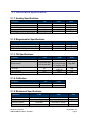
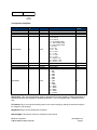
2.1 Performance Specifications
2.1.1 Heading Specifications
Parameter
TCM3
TCM5
Units
Accuracy with <65º of tilt
Accuracy with <80º of tilt
Resolution
Repeatability[1]
Max Dip Angle
0.5º
0.8º
0.1º
0.05º
85º
0.3º
0.5º
0.1º
0.05º
85º
Deg RMS
Deg RMS
Deg RMS
Deg RMS
Deg
[1] Repeatability is based on statistical data at ±3 sigma limit about the mean.
2.1.2 Magnetometer Specifications
Parameter
TCM3
TCM5
Units
Calibrated Field Measurement Range
Magnetic Resolution
Magnetic Repeatability
±80
±0.05
±0.1
±80
±0.05
±0.1
µT
µT
µT
2.1.3 Tilt Specifications
Parameter
TCM3
TCM5
Units
Pitch Accuracy
0.2º
Deg RMS
Roll Accuracy
0.2º for pitch <65º
0.5º for pitch <80º
0.2º
0.2º for pitch <65º
0.5º for pitch <80º
1.0 for pitch <86º
±90º pitch
±180º roll
<0.01º
0.05º
Tilt Range
±80º
Tilt Resolution
Tilt Repeatability[1]
<0.01º
0.05º
Deg RMS
Deg
Deg
Deg RMA
1] Repeatability is based on statistical data at ±3 sigma limit about the mean.
2.1.4 Calibration
Parameter
Hard Iron Calibration
Soft Iron Calibration
TCM3
TCM5
Yes
Yes
Yes
Yes
2.1.5 Mechanical Specifications
Parameter
Dimensions (LxWxH)
Weight
Mounting Options
Connector for RS-232
TCM3
TCM5
Units
3.5 x 4.3 x 1.3
<7
Screw mounts/Standoffs
Horizontal
9-pin
3.5 x 4.3 x 1.3
<7
Screw mounts/Standoffs
Horizontal or vertical
9-pin
cm
grams
PNI Sensor Corporation
TCM3 & TCM5 User Manual – Sept 2012
Doc #1007537 r12
Page 5
2.1.6 I/O Specifications
Parameter
Time to Initial Good Data from
Power On1
Time to Initial Good Data from
Sleep Mode1
Maximum Sample Rate2
RS-232 Communication Rate
Output Formats
TCM3
TCM5
Units
<210
<210
msec
<80
<80
msec
~30
~30
300 to 115200
300 to 115200
Binary High Performance Protocol
samples/sec
baud
[1] FIR taps set to “0”.
[2] The maximum sample rate is dependent on the strength of the magnetic field, and typically will be from 25 to 32
samples/sec.
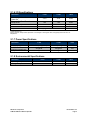
2.1.7 Power Specifications
Parameter
Supply Voltage
Current Draw at
maximum sample rate
Sleep Mode
TCM3
TCM5
Units
3.8 to 5 V (unregulated)
3.8 to 5 V (unregulated)
VDC
20 typical
20 typical
mA
0.6 typical
0.6 typical
mA
2.1.8 Environmental Specifications
Parameter
Operating Temperature
Storage Temperature
PNI Sensor Corporation
TCM3 & TCM5 User Manual- Sept 2011
TCM3
TCM5
Units
-40º to 85º
-40º to 85º
-40º to 85º
-40º to 85º
C
C
Doc #1007537 r12
Page 6
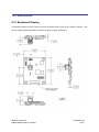
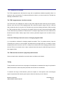
2.2 Mechanicals
2.2.1 Mechanical Drawing
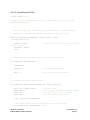
The default orientation for the TCM is for the silk-screened arrow to point in the “forward” direction. That
puts the edge opposite of the Molex connector as the front edge of the board.
PNI Sensor Corporation
TCM3 & TCM5 User Manual – Sept 2012
Doc #1007537 r12
Page 7
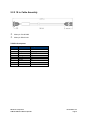
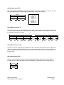
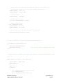
2.2.2 18 in. Cable Assembly
Molex p/n 51146-0900
Molex p/n 50641-8141
TCM Pin Descriptions
Pin
Wire Color
Description
1
2
3
4
5
6
7
8
9
Black
Gray
Green
Orange
Violet
Brown
Yellow
Blue
Red
Power Ground
NC
R2-232 Ground
NC
NC
NC
TxD
RxD
5 VDC
PNI Sensor Corporation
TCM3 & TCM5 User Manual- Sept 2011
Doc #1007537 r12
Page 8
3 Installation of the TCM
This section describes how to configure, program, and control the TCM in your host system. To install the
TCM into your system, follow these steps:
Make electrical connections to the TCM
Evaluate the TCM using the included TCM Studio Program
Choose a mounting location
Mechanically mount the TCM
Perform user calibration
Before you install the module, it can be evaluated with the TCM Studio outside of your system. Please
see section 4.1 TCM Studio.
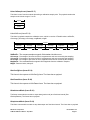
3.1 Electrical Connections
Included with the TCM Interface Kit is a cable to allow for the unit to be connected to your host system.
On one end of the cable is the connector needed to mate with the TCM3/5. The cable’s wires are color
coded as indicated below.
PNI also has a 6-foot cable with a DB9 connector attached. Please contact PNI Corporation for purchasing information.
TCM Pin Descriptions
Pin
Wire Color
Description
1
2
3
4
5
6
7
8
9
Black
Gray
Green
Orange
Violet
Brown
Yellow
Blue
Red
Power Ground
NC
R2-232 Ground
NC
NC
NC
TxD
RxD
5 VDC
PNI Sensor Corporation
TCM3 & TCM5 User Manual – Sept 2012
Doc #1007537 r12
Page 9
3.2 Where to Install
The TCM’s magnetometers’ wide dynamic range and its sophisticated calibration algorithms allow it to
operate in many environments. For optimal performance however, you should mount the TCM with the
following considerations in mind:
The TCM’s magnetometers should not saturate
The TCM can be user calibrated to correct for large static magnetic fields created by the host system.
However, each axis of the TCM’s magnetometers has a maximum dynamic range of ±80 µT; if the total
field exceeds this value for any axis, the TCM will not give accurate heading information. When mounting
the TCM, consider the effect of any sources of magnetic fields in the local environment that when added
to the earth’s field may saturate the TCM’s sensors. For example, large masses of ferrous metals such as
transformers and vehicle chassis, large electric currents, permanent magnets such as electric motors,
and so on.
Locate the TCM away from local sources of changing magnetic fields
It is not possible to calibrate for changing magnetic anomalies. Thus, for greatest accuracy, keep the
TCM away from sources of local magnetic anomalies that will change with time; for instance, electric
equipment that will be turned on and off or nearby ferrous bodies that will be changing positions. Make
sure the TCM is not mounted close to cargo or payload areas that may be loaded with large sources of
local magnetic fields.
The TCM should be mounted in a physically stable location
Choose a location that is isolated from excessive shock, oscillation, and vibration.
Testing
Testing should be performed in the early stages of development to understand the range of any distortion
fields and transients so that component placement can take this into consideration.
To determine the range of field distortion, place the compass in a fixed position, then move/energize
suspect components while observing the output to determine when they are an influence.
PNI Sensor Corporation
TCM3 & TCM5 User Manual- Sept 2011
Doc #1007537 r12
Page 10
To determine if the mounting locations magnetic field is within the dynamic range of the compass, the
following test should be performed:
With the compass mounted, rotate and tilt the systems in as many positions as possible. While doing so,
monitor the magnetometer outputs, observing if the maximum dynamic range is exceeded.
It is
preferable to have some margin before hitting the dynamic range limit of the module.
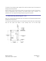
3.3 Mechanically Mounting the TCM
Refer to the TCM Dimensional Specification later in this manual for the TCM board dimensions and the
orientation of the reference frame.
The TCM is factory calibrated with respect to the mounting holes, as shown below, thus it must be aligned
within
the
host
system
with
PNI Sensor Corporation
TCM3 & TCM5 User Manual – Sept 2012
respect
to
these
mounting
holes,
not
the
board
edges.
Doc #1007537 r12
Page 11
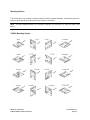
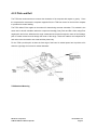
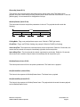
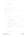
Mounting Options
The TCM is able to be mounted in various positions to allow for greater flexibility. All reference points are
based on the white silk-screened arrow on the top side of the board.
Note: The board depicted below is for illustration purposes only and does not show the actual TCM
board.
TCM3/5 Mounting Options
PNI Sensor Corporation
TCM3 & TCM5 User Manual- Sept 2011
Doc #1007537 r12
Page 12
4 Using the TCM
TCM Studio
User Calibration
Binary Protocol
Code Examples
4.1 TCM Studio
The TCM Evaluation software communicates with the TCM through the COM port of your PC. It puts an
easy-to-use interface onto the Binary command language used by the TCM, so that instead of issuing
command codes manually, you can use buttons, check boxes, and dialog boxes. It reads the Binary
responses of the TCM output strings and formats its sensor data into labeled and easy-to-read data
fields. The program also includes the ability to log and save the outputs of the TCM to a file. All of this is
so that you may begin to learn the capabilities of the TCM while using the TCM Studio program’s more
friendly interface. Check the PNI website for the latest updates at www.pnicorp.com.
4.1.1 Install the TCM Studio program onto a Windows system:
1. Drag the “TCM Studio.exe” to the working directory of your computer.
2. Move the Quesa plug-in (Quesa.dll) into either the Windows System or System32 folder. Quesa
is the OpenGL rendering engine and the 3D Model of the TCMStudio will not run without it.
For Windows 2000/NT copy to: /WinNT/System32 folder
For Windows XP copy to: /Windows/System32 folder
To install the TCM Studio program onto a Mac OSX system:
1. Drag the “TCM Studio” to the working directory of your computer.
2. Move the Quesa plug-in (Quesa) to: /Library/CFMSupport
PNI Sensor Corporation
TCM3 & TCM5 User Manual – Sept 2012
Doc #1007537 r12
Page 13
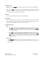
4.1.2 Connection Tab
Initial Connection:
1.
2.
3.
4.
Select 38400 as the baud rate.
Select the serial port the unit is plugged into.
Click on the <Connect> button.
Once a connection is made the “Connected” light will turn green and the Module, Firmware Version and Serial Number will be displayed.
Change Baud Rate:
1.
2.
3.
4.
Select new baud rate for the module.
Click on the <Power Down> button.
Select same baud rate for the computer.
Click on the <Power Up> button.
Change Modules:
Once connection has been made, the TCM Studio will remember the last settings. Any time a module is
switched out, clicking on the <Connect> button once the new module is attached will reestablish a
connection as long as the module baud rate is the same as the previous unit.
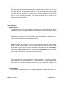
4.1.3 Configuration Tab
Note: No settings will be changed in the unit until the <SAVE> button has been selected.
Mounting Options:
Note: If the selection is grayed out or not listed the unit connected does not support this feature.
Refer to “Mechanically Mounting – mounting option” section for additional information on
mounting options.
Standard: When selected the unit is to be mounted with the main board in a horizontal position (the
Z axis magnetic sensor is vertical).
Standard 90 Degrees: When selected the unit is to be mounted with the main board in a horizontal
position but rotated so the arrow is pointed 90 degrees clockwise from the front of the host system.
Standard 180 Degrees: When selected the unit is to be mounted with the main board in a horizontal
position but rotated so the arrow is pointed 180 degrees from the front of the host system.
Standard 270 Degrees: When selected the unit is to be mounted with the main board in a horizontal
position but rotated so the arrow is pointed 270 degrees clockwise from the front of the host system.
PNI Sensor Corporation
TCM3 & TCM5 User Manual- Sept 2011
Doc #1007537 r12
Page 14
X Sensor Up: When selected the unit is to be mounted with the main board in a vertical position (the
X axis magnetic sensor is vertical).
X Sensor Up Plus 90 Degrees: When selected the unit is to be mounted with the main board in a
vertical position (the X axis magnetic sensor is vertical) and rotated 90 degrees clockwise from the
front of the host system.
X Sensor Up Plus 180 Degrees: When selected the unit is to be mounted with the main board in a
vertical position (the X axis magnetic sensor is vertical) and rotated 180 degrees from the front of the
host system.
X Sensor Up Plus 270 Degrees: When selected the unit is to be mounted with the main board in a
vertical position (the X axis magnetic sensor is vertical) and rotated 270 degrees clockwise from the
front of the host system.
Y Sensor Up: When selected the unit is to be mounted with the main board in a vertical position (the
Y axis magnetic sensor is vertical).
Y Sensor Up Plus 90 Degrees: When selected the unit is to be mounted with the main board in a
vertical position (the Y axis magnetic sensor is vertical) and rotated 90 degrees clockwise from the
front of the host system.
Y Sensor Up Plus 180 Degrees: When selected the unit is to be mounted with the main board in a
vertical position (the Y axis magnetic sensor is vertical) and rotated 180 degrees from the front of the
host system.
Y Sensor Up Plus 270 Degrees: When selected the unit is to be mounted with the main board in a
vertical position (the Y axis magnetic sensor is vertical) and rotated 270 degrees clockwise from the
front of the host system.
Z Sensor Down: When selected the unit is to be mounted with the main board in a vertical position
(the Z axis magnetic sensor is vertical).
Z Sensor Down Plus 90 Degrees: When selected the unit is to be mounted with the main board in a
vertical position (the Z axis magnetic sensor is vertical) and rotated 90 degrees clockwise from the
front of the host system.
PNI Sensor Corporation
TCM3 & TCM5 User Manual – Sept 2012
Doc #1007537 r12
Page 15
Z Sensor Down Plus 180 Degrees: When selected the unit is to be mounted with the main board in
a vertical position (the Z axis magnetic sensor is vertical) and rotated 180 degrees from the front of
the host system.
Z Sensor Up Plus 270 Degrees: When selected the unit is to be mounted with the main board in a
vertical position (the Z axis magnetic sensor is vertical) and rotated 270 degrees clockwise from the
front of the host system.
PNI Sensor Corporation
TCM3 & TCM5 User Manual- Sept 2011
Doc #1007537 r12
Page 16
North Reference:
Magnetic: When the “Magnetic” radio button is selected, heading will be relative to Magnetic North.
True: When the “True” radio button is selected, heading will be relative to True North. To use North
Heading in “True” mode, the declination needs to be set in the “Declination” window. Refer to “Using
the TCM Declination Value” section for more information.
Endianess:
Use to select either Big Endian or Little Endian; default is Big Endian.
Filter Settings:
Taps: Use to select either a 0 (no filter), 4, 8, 16, or 32 samples and apply the values to a FIR filter
prior to calculating the heading. These filters allow for a much more stable reading, but can make the
acquisition of the data by the program slower. The default setting is 32.
Acquisition Parameters:
Mode:
When “Poll” is selected the TCM Studio program requests the data from the unit, and once it
has been sent, the program will request the data again at the interval set in the “Poll Time”
box. If the time is set to 0 then the TCM Studio will request the data as soon as the previous
request has been fulfilled.
When “Push” is selected the unit will be in Interval Mode, which is internal to the unit. Once
the unit has been set to Interval Mode and the interval time has been set in the “Interval
Time” setting box, the unit will send out the preset data at the desired interval without prompting. If the interval is set to 0 then the unit will send the data as soon as the previous data
stream has been sent.
Acquire Time:
The “Acquire Time” setting box sets the time between samples taken by the unit. This is an
internal setting that is NOT tied to the time with which the unit transmits the data out to the
program or host.
PNI Sensor Corporation
TCM3 & TCM5 User Manual – Sept 2012
Doc #1007537 r12
Page 17
Flush Filters:
The filtering is set to only update the filter with the last sample taken, for example once the initial
32 samples are taken any new sample is added to the end with the first sample being dropped.
In the case where the “Acquire Time” is set to a value it would be prudent to set the unit to flush
the filter prior to calculating the heading.
This flushing will require the unit to take 32 new
samples to use for the calculation.
Note: If the “Flush Filters” checkbox is checked, it will take longer for the unit to output updated data.
User Cal Settings:
Stability Checking:
By default the unit will wait for the readings to be stable for 3 consecutive readings when in
calibration mode prior to saving the sample for use in the calibration. This is why the unit must be
held steady between points during the User Calibration. This stability helps to ensure a proper
heading and allow for higher accuracy, but it also takes more time. If the user de-selects the
check box, then the unit will NOT wait for a stable reading and instead take a reading once the
minimum change between points threshold has been met.
Automatic Sampling:
When selected the unit will take a point once the minimum change requirement and the stability
check, if selected, has been satisfied. If the user wants to have more control over when the point
will be taken then Auto Sampling should be deselected. Once deselected, the <Take Sample>
button on the Calibration tab will be active. Selecting the <Take Sample> button will indicate to
the unit to take a sample once the minimum requirements are met.
Calibration Points:
The user can select the number of points to take during a calibration. The minimum number of
points needed for a successful calibration is 12. The unit will need to be rotated through at least
180 degrees in the horizontal plane with a minimum of at least 1 positive and 1 negative Pitch
and at least 1 positive and 1 negative Roll as part of the 12 points.
Enable 3D Model:
Some computer systems may not have the graphics capability to render the 3D Model, for this
reason it may be necessary to turn off this feature.
PNI Sensor Corporation
TCM3 & TCM5 User Manual- Sept 2011
Doc #1007537 r12
Page 18
Default:
This button will set the TCM Studio program back to the factory default settings.
Revert:
This button will have the TCM Studio program read the settings from the unit and display them on the
screen.
4.1.4 Calibration Tab
Note:
The default settings of the unit are recommended for the highest accuracy and
quality of calibration.
Samples:
1. Click on the <Start> button to begin.
2. To take a sample point, the unit will need to be held steady for a short time. Once the window indicates the next number, the unit can be moved some distance and held steady for the next sample. A minimum change of 30 degrees in heading or tilt is required for a sample to be taken. The
larger the distance between points the better. The amount of Pitch and Roll during the calibration
will determine the amount of Pitch and Roll the unit will be able to compensate for during use.
Once the pre-set number of samples has been taken the calibration is complete.
Note: The minimum points the unit can use for a successful calibration is 12. The unit will
need to be rotated through at least 180 degrees in the horizontal plane with minimum of at
least 1 positive and 1 negative Pitch and Roll as part of the 12 points.
Results:
1. Once the calibration is complete the “Coverage” window will indicate the quality of the calibration.
The X, Y, and Z values show a percentage of each vector that has been covered during the calibration. The only way to get a Z value greater than 50% would be to take some points with the
unit upside-down. The value shown in µT refers to the standard deviation of the measured samples when compared to the calculated values. The smaller the number the better. If a better
score is needed, click on the <Start> button to begin a new calibration.
Note: The value in µT only refers to the quality of the calibration and NOT the accuracy of
the heading. It is possible to have a “good” calibration but poor accuracy if the field the unit
is exposed to during use is not the same as that which was present during the calibration.
2. If the calibration is sufficient then click on the <Save> button to save the calibration. If this button
is not selected then the unit will need to be recalibrated after a power cycle.
PNI Sensor Corporation
TCM3 & TCM5 User Manual – Sept 2012
Doc #1007537 r12
Page 19
Current Configuration:
Stability Checking: Indicates if the Stability Checking option has been selected.
Automatic Sampling: Indicates if the Automatic Sampling option has been selected.
Number of samples is: Indicates the number of samples to be taken for the current calibration.
Options:
Audible Feedback: If selected the TCM Studio will give an audible signal once a calibration point
has been taken.
Clear:
This button will clear the user calibration in the unit. Once selected, the unit will revert back to its
factory calibration.
4.1.5 Test Tab
Current Reading:
Once the <GO> button is selected the unit will begin outputting Heading, Pitch and Roll information.
Selecting the <Stop> button or changing tabs will halt the output of the unit.
Contrast:
Reverses the background color of the current reading window.
Acquisition Settings:
This window indicates the pertinent setting information.
3D Model:
The helicopter will follow the movement of the attached module and give a clear representation of the
module’s orientation.
PNI Sensor Corporation
TCM3 & TCM5 User Manual- Sept 2011
Doc #1007537 r12
Page 20
4.1.6 Data Logger Tab
1.
2.
3.
4.
5.
Select the data to log in the “Data” window.
Use Shift-Ctrl-Click and Ctrl-Click to select multiple items.
Click on the <GO> button to start logging; click the <STOP> button to stop logging.
Click on the <Export> button to save the data to a file.
Click on the <Clear> button to clear the data from the window.
Note: The data logger use ticks for time reference. A tick is 1/60 second.
4.1.7 System Log Tab
Export:
Select the <Export> button to save the system log to a file.
Graph
The graph provides a 2-axis (X,Y) plot of the measured field strength. The graph can be used to visually see hard and soft iron effects within the environment measured by the TCM module as well as corrected output after a user calibration has been performed.
PNI Sensor Corporation
TCM3 & TCM5 User Manual – Sept 2012
Doc #1007537 r12
Page 21
4.2 User Calibration
All compasses can perform well in a controlled environment, where the ambient magnetic field consists
solely of the earth’s field. In most practical applications, however, an electronic compass module will be
mounted in a host system such as a vehicle that can contain large sources of local magnetic fields:
ferrous metal chassis, transformer cores, electrical currents, and permanent magnets in electric motors.
By performing the user calibration procedure, you allow the TCM to identify the major sources of these
local magnetic anomalies and subsequently cancel out their effects when measuring the earth’s magnetic
field for computing compass headings. When you perform the user calibration procedure, the TCM takes
a series of magnetic field measurements. It analyzes these total field measurements in order to identify
the components that are created by the earth’s field, which is the desired signal, from those components
that are generated by the local environment, which we wish to subtract out.
The end goal of the procedure for the TCM is to have an accurate measurement of the static threedimensional magnetic field vector generated by its host system at its mounting location. This vector is
subsequently subtracted out of run-time field measurement to yield the resultant earth’s field vector.
One major benefit from the TCM’s triaxial magnetometer/triaxial accelerometer system configuration is its
ability to compensate for distortion effects in all orientations throughout its usable tilt range. As we have
mentioned, a compass must measure the local field vector generated by the host system at its current
position within the system in order to accurately calibrate. Because the TCM’s magnetometer is strappeddown, or fixed with respect to its host system, this local field vector does not change as the host system’s
attitude changes, allowing the TCM to accurately compensate in all pitch and roll orientations. Gimbaled
fluxgates, for instance, are unable to provide accurate calibration in non-level orientations because its
magnetometers, being gimbaled, change position with respect to the host system as attitude changes.
This presents a different local distortion field than that measured during calibration.
Key Points
The minimum points the unit can use for a successful calibration is 12.
The unit will need to be rotated through at least 180 degrees in the horizontal plane including at
least 1 positive and 1 negative Pitch and Roll movement.
Tilt as much as possible during the calibration. This allows the compass to take full advantage of
the 3-axis magnetometer.
You are trying to get an even sampling of the magnetic field over as many headings and tilts as
possible, including upside down if possible.
Pay attention to the coverage percentage. The lower the percentage the less accurate the compass.
PNI Sensor Corporation
TCM3 & TCM5 User Manual- Sept 2011
Doc #1007537 r12
Page 22
4.2.1 Calibration Theory
The exact calibration method will depend on the actual settings of the calibration parameters. An
example of the various settings and their effect can be seen in the TCM Studio – Evaluation
Software section.
The main object of the calibration is to allow the TCM to calibrate out any distortions to the magnetic
field caused by the host system. To that end the TCM needs to be mounted within the host system
and the entire application needs to be moved as a single unit during the calibration. Movement
should include at least 180˚ of horizontal rotation, but to achieve the highest accuracy a full 360˚ of
horizontal rotation with as many different tilt angles as possible during the rotation is required.
To achieve the highest accuracy throughout the TCM’s entire tilt range, the unit will need to be tilted
through the entire range. For example, if the unit is only tilted through 40˚ of pitch and roll, then the
heading information from the TCM will only be accurate through 40˚ of pitch and roll. For maximum
performance the TCM should be exposed to tilt angles covering a full 360°, meaning upside down.
Recommended calibration procedure for taking the minimum number of sample points
follows.
4.2.2 Hard and Soft Iron Effects
Hard iron distortions are caused by permanent magnets and magnetized steel or iron object within close
proximity to the sensors. This type of distortion will remain constant and in a fixed location relative to the
sensors for all heading orientations. Hard-iron distortions will add a constant magnitude field component
along each axis of sensor output and can be easily compensated for using a simple saturation method.
Soft-iron distortions are the result of interactions between the Earth’s magnetic field and any
magnetically “soft” material within close proximity to the sensors. In technical terms, soft materials have a
high permeability. The permeability of a given material is a measure of how well it serves as a path for
magnetic lines of force, relative to air, which has an assigned permeability of one.
The TCM 3-axis digital compass features soft-iron and hard-iron correction.
PNI Sensor Corporation
TCM3 & TCM5 User Manual – Sept 2012
Doc #1007537 r12
Page 23
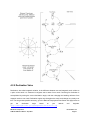
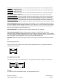
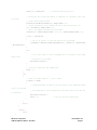
4.2.3 Pitch and Roll
The TCM uses accelerometers to measure the orientation of the compass with respect to gravity. Since
the compass also measures the complete magnetic field, the TCM can correct for the tilt of the compass
to provide an accurate heading.
The TCM utilizes Euler angles as the method for determining accurate orientation. This method is the
same used in aircraft orientation where the outputs are Heading (Yaw), Pitch and Roll. When using Euler
angles pitch and roll are defined as the angle rotated around an axis through the center of the fuselage;
pitch is rotation around an axis through the center of the wings. These two rotations are independent of
each other since the rotation axes rotate with the plane body.
For the TCM a positive pitch is when the front edge of the board is rotated upward and a positive roll is
when the right edge of the board is rotated downward.
TCM Standard Mounting
PNI Sensor Corporation
TCM3 & TCM5 User Manual- Sept 2011
Doc #1007537 r12
Page 24
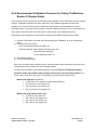
4.2.4 Recommended Calibration Procedure For Taking The Minimum
Number Of Sample Points
This procedure provides instructions for performing a user calibration of the TCM 3/5/5L family of modules
using the TCMStudio application and demo cable. All of the TCMStudio application functions are
available in the TCM unit’s binary protocol allowing for this procedure to be translated into a user’s
imbedded solution. The scope of this procedure covers the calibration process only, for connecting to the
unit or other issues refer to the quick start guide or users manual. This calibration sequence
demonstrates a good distribution of the minimum sample points, additional points may be added.
1) With the TCM module connected and communicating with TCMStudio, go to the configuration
page.
2) Configure the unit as follows:
In the Filter Settings window set Taps to 32
Calibration Settings: Select Stability Checking check box
Select Automatic Sampling
Choose Calibration points: 12
3) Press the Save button.
4) Go to the calibration page.
Note: Once you begin taking calibration points, pausing between desired calibration points will cause
unintentional points to be taken with auto sampling enabled.
You will move the module to the following positions noting that these are not absolute heading
directs but rather approximate heading changes referenced to your first heading sample. You
do not need to know which way north is. The following 12 samples points will be taken:
Module with slight pitch (-5° to +5°)
0° yaw with 10°-20° positive roll (initial starting position)
90° yaw with 10°-20° negative roll
180° yaw with 10°-20° positive roll
270° yaw with 10°-20° negative roll
Module with large positive pitch (>+45°)
30° with 10°-20° positive roll
120° with 10°-20° negative roll
210° with 10°-20° positive roll
300° with 10°-20° negative roll
PNI Sensor Corporation
TCM3 & TCM5 User Manual – Sept 2012
Doc #1007537 r12
Page 25
Module with large negative pitch (<-45°)
60° with 10°-20° positive roll
150° with 10°-20° negative roll
240° with 10°-20° positive roll
330° with 10°-20° negative roll.
5) Hold the module level and stable.
6) Press the Start button and wait for a sample to be taken.
7) Rotate the module to the next heading, approximately 90 degrees, and hold the module stable
until the next sample is taken.
8) Repeat this until all 12 samples are taken.
9) Press the Save button.
10) Calibration results will be displayed in the Results window with Coverage X, Y and Z in % and
Std Deviation of Magnetic Field Magnitude in uT. The Coverage score is how much of the sphere
was each sensor exposed to in percent to describe the shape of the distortion to be corrected for.
You want a score of 85% or better for X and Y, with the above method Z will be below 50%. The
Std Deviation score should have a result of 0.1uT or better. The Std. Deviation score represents
how well the distortion was able to be described and compensated for. A poor score will result if
sources of distortion to be calibrated out moved during the user calibration relative to the module.
A magnetically noisy environment will also result in a poor calibration.
PNI Sensor Corporation
TCM3 & TCM5 User Manual- Sept 2011
Doc #1007537 r12
Page 26
4.2.5 Declination Value
Declination, also called magnetic variation, is the difference between true and magnetic north, relative to
a point on the earth. It is measured in degrees east or west of true north. Correcting for declination is
accomplished by storing the correct declination angle, and then changing the heading reference from
magnetic north to true north. Declination angles vary throughout the world, and change very slowly over
time. For the greatest possible accuracy, go to the National Geophysical Data Center web page below to
get
the
declination
angle
based
on
your
latitude
and
longitude:
http://www.ngdc.noaa.gov/geomagmodels/Declination.jsp
PNI Sensor Corporation
TCM3 & TCM5 User Manual – Sept 2012
Doc #1007537 r12
Page 27
4.2.6 Other Limitations
As discussed, the TCM models local disturbances as a static magnetic vector contribution to the earth’s
field. Any local fields, which are not static, will create errors. You cannot calibrate for anomalies that are
not fixed with respect to the compass. For example, you may know that the TCM will be used in close
proximity to other vehicles. You cannot calibrate for the effects of these other vehicles, as they will be
moving with respect to the TCM. This is a limitation universal to all compasses. Consider, therefore, the
TCM’s position relative to any potential sources of field that will not be static: magnetic cargo or payloads
that may be placed in close proximity, fans or other electrical equipment that may be turned on and off,
and so on.
The TCM can calibrate for any environment that creates a magnetic field that does not exceed the
dynamic range of its magnetometers.
PNI Sensor Corporation
TCM3 & TCM5 User Manual- Sept 2011
Doc #1007537 r12
Page 28
4.3 Binary Protocol – RS232 Interface
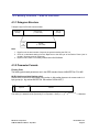
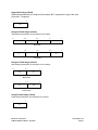
4.3.1 Datagram Structure
Transport Layer for RS-232 communication:
ByteCount
(UInt16)
Packet Frame
(1 - 4092 UInt8)
Frame
ID
(UInt8)
CRC-16
(UInt16)
Payload
(1 - 4091 UInt8)
Note:
1. ByteCount is the total number of bytes in the packet including the CRC-16
2. CRC-16 is calculated starting from the ByteCount to the last byte of the Packet Frame (see included C function at end of document).
3. ByteCount and CRC-16 are always transmitted in BIG ENDIAN.
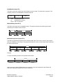
4.3.2 Parameter Formats
Floating Point
The floating-point based parameters are in the IEEE standard format, ANSI/IEEE Std 754-1985.
64-Bit (double precision floating point)
Shown below is the 64-bit float format in big endian, in little endian bytes are in reverse order in 4
byte groups (ie: big endian:ABCDEFGH little endian: DCBA HGFE).
63 62
S
52 51
Exponent
0
Mantissa
S
(Exponent-1023)
The value (v) is determined as (if and only if 0 < Exponent < 2047): v = (-1) * 2
PNI Sensor Corporation
TCM3 & TCM5 User Manual – Sept 2012
* 1.Mantissa
Doc #1007537 r12
Page 29
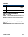
32-Bit (single precision floating point)
Shown below is the 32-bit float format in big endian, in little endian all 4 bytes are in reverse order
(LSB first).
3130
S
23 22
0
Exponent
Mantissa
S
(Exponent-127)
The value (v) is determined as (if and only if 0 < Exponent < 255): v = (-1) * 2
* 1.Mantissa
Note: Please refer to ANSI/IEEE Std 754-1985 for more information. It is also recommended that
you refer to the compiler you are using on how it implements floating-point formats.
Signed 32-bit Integer (SInt32)
SInt32 based parameters are signed 32 bit numbers (2’s compliment). Bit 31 represents the sign of
the value (0=positive, 1=negative)
31
24 23
16 15
8 7
msb
0
lsb
Big Endian
7
0 15
8 23
lsb
16 31
24
msb
Little Endian
Signed 16-bit Integer (SInt16)
SInt16 based parameters are signed 16 bit numbers (2’s compliment). Bit 15 represents the sign of
the value (0=positive, 1=negative)
15
8 7
msb
0
lsb
Big Endian
7
0 15
lsb
8
msb
Little Endian
PNI Sensor Corporation
TCM3 & TCM5 User Manual- Sept 2011
Doc #1007537 r12
Page 30
Signed 8-bit Integer (SInt8)
UInt8 based parameters are unsigned 8-bit numbers. Bit 7 represents the sign of the value
(0=positive, 1=negative)
7
0
byte
Unsigned 32-bit Integer (UInt32)
UInt32 based parameters are unsigned 32 bit numbers.
31
24 23
16 15
8 7
msb
0
lsb
Big Endian
7
0 15
8 23
16 31
lsb
24
msb
Little Endian
Unsigned 16-bit Integer (UInt16)
UInt16 based parameters are unsigned 16 bit numbers.
15
8 7
msb
0
lsb
Big Endian
7
0 15
lsb
8
msb
Little Endian
Unsigned 8-bit Integer (UInt8)
UInt8 based parameters are unsigned 8-bit numbers.
7
0
byte
PNI Sensor Corporation
TCM3 & TCM5 User Manual – Sept 2012
Doc #1007537 r12
Page 31
Boolean
Boolean is a 1-byte parameter that MUST have the value 0 (false) or 1 (true).
7
0
byte
4.3.3 Commands & Communication Frames
Overview:
Frame
ID
1
2
3
4
5
6
7
8
9
10
11
Command
Description
kGetModInfo
kModInfoResp
kSetDataComponents
kGetData
kDataResp
kSetConfig
kGetConfig
kConfigResp
kSave
kStartCal
kStopCal
Queries the modules type and firmware revision number.
Response to kGetModInfo
Sets the data components to be output.
Queries the module for data
Response to kGetData
Sets internal configurations in the module
Queries the module for the current internal configuration value
Response to kGetConfig
Commands the module to save internal and user calibration
Commands the module to start user calibration
Commands the module to stop user calibration
Sets the FIR filter settings for the magnetometer & accelerometer
sensors.
Queries for the FIR filter settings for the magnetometer &
accelerometer sensors.
Contains the FIR filter settings for the magnetometer &
accelerometer sensors.
Used to completely power-down the module
Response to kSave
Sent from the module after taking a calibration sample point
Contains the calibration score
Response to kSetConfig
Response to kSetParam
Commands the module to output data at a fixed interval
Commands the module to stop data output at a fixed interval
Sent after wake up from power down mode
Sets the sensor acquisition parameters
Queries for the sensor acquisition parameters
Response to kSetAcqParams
Response to kGetAcqParams
Response to kPowerDown
Clears user calibration coefficients
Response to kFactoryUserCal
Commands the unit to take a sample during user calibration
12
kSetParam
13
kGetParam
14
kParamResp
15
16
17
18
19
20
21
22
23
24
25
26
27
28
29
30
31
kPowerDown
kSaveDone
kUserCalSampCount
kUserCalScore
kSetConfigDone
kSetParamDone
kStartIntervalMode
kStopIntervalMode
kPowerUp
kSetAcqParams
kGetAcqParams
kAcqParamsDone
kAcqParamsResp
kPowerDownDone
kFactoryUserCal
kFactorUserCalDone
kTakeUserCalSample
PNI Sensor Corporation
TCM3 & TCM5 User Manual- Sept 2011
Doc #1007537 r12
Page 32
kGetModInfo (frame ID 1)
This frame queries the module's type and firmware revision number. The frame has no payload. The
complete packet for the kGetModInfo command would be:
0005
with
01
0005
01
EFD4
EFD4
being the byte count
kGetModInfo command
CRC-16 checksum
kModInfoResp (frame ID 2)
This frame is the response to kGetModInfo frame. The payload contains the module type identifier
followed by the firmware revision number.
Frame ID
Payload
2
Type
Revision
kUlnt8
UInt32
UInt32
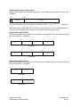
kSetDataComponents (frame ID 3)
This frame sets the data components in the module's data output. This is not a query for the module's
data (see kGetData). The first byte of the payload indicates the number of data components followed by
the data component IDs.
Payload
Count
ID1
ID2
ID3
IDCount
UInt8
UInt8
UInt8
UInt8
UInt8
Example:
To query the heading and pitch, the payload should contain:
Payload
3
2
5
24
Frame ID
ID Count
Heading ID
Pitch ID
When querying for data (kGetData frame), the sequence of the data component output follows the
sequence of the data component IDs as set in this frame.
PNI Sensor Corporation
TCM3 & TCM5 User Manual – Sept 2012
Doc #1007537 r12
Page 33
Component Identifiers
Component
DataComponentID
(decimal)
Format
Units
Range
kHeading
kTemperature
5
7
Float32
Float32
degrees
˚ Celsius
kDistortion
8
Boolean
True or False
kCalStatus
9
Boolean
True or False
kPCalibrated
kRCalibrated
kIZCalibrated
kPAngle
kRAngle
KXAligned
KYAligned
KZAligned
21
22
23
24
25
27
28
29
Float32
Float32
Float32
Float32
Float32
Float32
Float32
Float32
G
G
G
degrees
degrees
T
T
T
0.0˚ to 359.9˚
-40˚ to 85˚
False (Default) =
no distortion
False (Default) =
not calibrated
-1.0 to 1.0
-1.0 to 1.0
-1.0 to 1.0
-90.0˚ to 90.0˚
-180.0˚ to 180.0˚
Component Types for kSetDataComponents & kDataResp frames
kHeading Compass heading output.
kTemperature This is sampled from the internal temperature sensor of the module. Its value is in °
Celsius and has an accuracy of +/- 3° C.
kDistortion Read only flag that indicates that at least one magnetometer axis reading is beyond +/- 80
µT.
kCalStatus Read only flag that indicates user calibration status. False (Default) = Not calibrated.
kPCalibrated, kRCalibrated & kIZCalibrated Factory calibrated Earth’s acceleration vector (G)
component output.
kPAngle, kRAngle Pitch and Roll angle outputs. Pitch is equal to -90.0˚ to 90.0˚ and Roll is equal to
-180.0˚ to 180.0˚.
kXAligned, kYAligned, kZAligned User calibration Earth’s magnetic field (M) vector component
output.
PNI Sensor Corporation
TCM3 & TCM5 User Manual- Sept 2011
Doc #1007537 r12
Page 34
kGetData (frame ID 4)
This frame queries the module for data. The frame has no payload. The complete packet for the
kGetModInfo command would be:
00 05
with
04
BF71
04
BF71
00 05 being the byte count
kGetData command
CRC-16 checksum
kDataResp (frame ID 5)
The frame is the response to kGetData frame. The first byte of the payload indicates the number of data
components then followed by the data component ID-value pairs. The sequence of the components Ids
follows the sequence set in the kSetDataComponents frame.
Payload
Count
ID1
ValueID1
ID2
ValueID2
IDCount
ValueIDCount
UInt8
UInt8
ID
Specific
UInt8
ID
Specific
UInt8
ID
Specific
Example:
If the response contains the heading and pitch output, the payload would look like:
2
5
359.9
24
10.5
ID Count
Heading ID
Heading
Output
(Float32)
Pitch ID
Pitch
Output
(Float32)
kSetConfig (frame ID 6)
This frame sets internal configurations in the module. The first byte of the payload is the configuration ID
followed by a format specific value. These configurations can only be set one at time.
Payload
Config ID
Value
UInt8
ID
Specific
Example:
To configure the declination, the payload would look like:
PNI Sensor Corporation
TCM3 & TCM5 User Manual – Sept 2012
Doc #1007537 r12
Page 35
1
10.0
Declination ID
Declination
Angle
(Float32)
Configuration Identifiers
Settings
Configuration
ID
Format
Units/ Range
kDeclination
kTrueNorth
kBigEndian
1
2
6
Float32
Boolean
Boolean
kMountingRef
10
UInt8
kUserCalStableCheck
kUserCalNumPoints
kUserCalAutoSampling
11
12
13
Boolean
UInt32
Boolean
kBaudRate
14
UInt8
-180˚ to 180˚
True or False
True or False
1 = Standard
2 = X axis up
3 = Y axis up
4 = -90° heading offset
5 = -180° heading offset
6 = -270° heading offset
7 = Z down
8 = X + 90°
9 = X + 180°
10 = X + 270°
11 = Y + 90°
12 = Y + 180°
13 = Y + 270°
14 = Z down + 90°
15 = Z down + 180°
16 = Z down + 270°
True or False
12 – 50
True or False
0 – 300
1 – 600
2 – 1200
3 – 1800
4 – 2400
5 – 3600
6 – 4800
7 – 7200
8 – 9600
9 – 14400
10 – 19200
11 – 28800
12 – 38400
13 – 57600
14 - 115200
Default
Values
0˚
False
True
1
True
50
True
12
kDeclination This sets the declination angle to determine True North heading. Positive declination is
easterly declination and negative is westerly declination. This is not applied until TrueNorth is set to
true.
kTrueNorth Flag to set compass heading output to true north heading by adding the declination angle to
the magnetic north heading.
kBigEndian Flag to set the Endianness of packets
kMountingRef This sets the reference orientation for the module.
PNI Sensor Corporation
TCM3 & TCM5 User Manual- Sept 2011
Doc #1007537 r12
Page 36
Standard: When selected the unit is to be mounted with the main board in a horizontal position (the Z
axis magnetic sensor is vertical).
X Sensor Up: When selected the unit is to be mounted with the main board in a vertical position (the X
axis magnetic sensor is vertical).
Y Sensor Up: When selected the unit is to be mounted with the main board in a vertical position (the Y
axis magnetic sensor is vertical).
Standard 90 Degrees: When selected the unit is to be mounted with the main board in a horizontal
position but rotated so the arrow is pointed 90 degrees counterclockwise to the front of the host system.
Standard 180 Degrees: When selected the unit is to be mounted with the main board in a horizontal
position but rotated so the arrow is pointed 180 degrees counterclockwise to the front of the host system.
Standard 270 Degrees: When selected the unit is to be mounted with the main board in a horizontal
position but rotated so the arrow is pointed 270 degrees counterclockwise to the front of the host system.
kUserCalStableCheck This flag is used during user calibration. If set to FALSE, the module will take a
point if the magnetic field has changed more than 23 µT in either axis. If set to TRUE the unit will take a
point if the magnetic field has a stability of 30µT in each direction and the previous point changed more
than 5µT and acceleration vector delta within 2 mg.
kUserCalNumPoints The maximum number samples taken during user calibration.
kUserCalAutoSampling This flag is used during user calibration. If set to TRUE, the module
continuously takes calibration sample points until the set number of calibration samples. If set to FALSE,
the module waits for kTakeUserCalSample frame to take a sample with the condition that a magnetic field
vector component delta is greater than 5 micro Tesla from the last sample point.
kBaudRate Baud rate index value. A power-down power-up cycle is required when changing the baud
rate.
kGetConfig (frame ID 7)
This frame queries the module for the current internal configuration value. The payload contains the
configuration ID requested.
Payload
Config ID
UInt8
kConfigResp (frame ID 8)
This frame is the response to kGetConfig frame. The payload contains the configuration ID and value.
Payload
Config ID
Value
UInt8
ID
Specific
Example:
If a request to get the set declination angle, the payload would look like:
PNI Sensor Corporation
TCM3 & TCM5 User Manual – Sept 2012
Doc #1007537 r12
Page 37
1
10.0
Declination ID
Declination
Angle
(Float32)
kSave (frame ID 9)
This frame commands the module to save internal configurations and user calibration to non-volatile
memory. Internal configurations and user calibration is restored on power up. The frame has no payload.
This is the ONLY command that causes the module to save information into non-volatile memory.
kStartCal (frame ID 10)
This frame commands the module to start user calibration with the current sensor acquisition parameters,
internal configurations and FIR filter settings.
kStopCal (frame ID 11)
This frame commands the module to stop calibration points sampling and calculate the calibration
score and coefficients.
PNI Sensor Corporation
TCM3 & TCM5 User Manual- Sept 2011
Doc #1007537 r12
Page 38
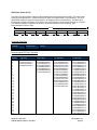
kSetParam (frame ID 12)
This frame sets the FIR filter settings for the magnetometer and accelerometer sensors. The second byte
of the payload indicates the x vector component of either the magnetometer or accelerometer. This is to
differentiate whether to apply the filter settings to the magnetometer or accelerometer. The third byte in
the payload indicates the number of FIR taps to use then followed by the filter taps. Each tap is a Float64.
The maximum number of taps that can be set is 32 and the minimum is 0 (no filtering). (See
Recommended FIR Filter Taps).
Payload
Parameter ID
Axis ID
Count
Value1
Value2
Value3
ValueCount
UInt8
UInt8
UInt8
ID
Specific
ID
Specific
ID
Specific
ID
Specific
Parameter Identifiers
Settings
Parameter ID
Format
KFIRConfig*
3
AxisID (UInt8) + Count (UInt8) + Value (Float64) + Value (Float64) + …
Recommended FIR Filter Tap Value
2 Count 4 Tap Filter
8 Tap Filter
16 Tap Filter
32 Tap Filter
1
2
3
4
5
6
7
8
9
10
11
12
13
14
15
16
17
18
19
20
21
22
23
24
25
26
27
28
29
30
31
32
01.9875512449729e-2
06.4500864832660e-2
01.6637325898141e-1
02.4925036373620e-1
02.4925036373620e-1
01.6637325898141e-1
06.4500864832660e-2
01.9875512449729e-2
07.9724971069144e-3
01.2710056429342e-2
02.5971390034516e-2
04.6451949792704e-2
07.1024151197772e-2
09.5354386848804e-2
01.1484431942626e-1
01.2567124916369e-1
01.2567124916369e-1
01.1484431942626e-1
09.5354386848804e-2
07.1024151197772e-2
04.6451949792704e-2
02.5971390034516e-2
01.2710056429342e-2
07.9724971069144e-3
01.4823725958818e-3
02.0737124095482e-3
03.2757326624196e-3
05.3097803863757e-3
08.3414139286254e-3
01.2456836057785e-2
01.7646051430536e-2
02.3794805168613e-2
03.0686505921968e-2
03.8014333463472e-2
04.5402682509802e-2
05.2436112653103e-2
05.8693165018301e-2
06.3781858267530e-2
06.7373451424187e-2
06.9231186101853e-2
06.9231186101853e-2
06.7373451424187e-2
06.3781858267530e-2
05.8693165018301e-2
05.2436112653103e-2
04.5402682509802e-2
03.8014333463472e-2
03.0686505921968e-2
02.3794805168613e-2
01.7646051430536e-2
01.2456836057785e-2
08.3414139286254e-3
05.3097803863757e-3
03.2757326624196e-3
02.0737124095482e-3
01.4823725958818e-3
04.6708657655334e-2
04.5329134234467e-1
04.5329134234467e-1
04.6708657655334e-2
PNI Sensor Corporation
TCM3 & TCM5 User Manual – Sept 2012
Doc #1007537 r12
Page 39
kGetParam (frame ID 13)
This frame queries the FIR filter settings for the magnetometer and accelerometer sensors. The first
byte of the payload is the kFIRConfig ID followed by the vector axis ID (byte).
Payload
Axis IDs
Parameter ID
Axis ID
UInt8
UInt8
kXAxis
kYAxis
kZAxis
kPAxis
kRAxis
=1
=2
=3
=4
=5
KIZAxis = 6
kParamResp (frame ID 14)
This frame contains the current FIR filter settings for either magnetometer or accelerometer sensors. The
second byte of the payload is the vector axis ID, the third byte is the number of filter taps then followed by
the filter taps. Each tap is a Float64.
Payload
Parameter ID
Axis ID
Count
Value1
Value2
Value3
ValueCount
UInt8
UInt8
UInt8
Filter Top
Value
ID
Specific
ID
Specific
ID
Specific
kPowerDown (frame ID 15)
This frame is used to completely power-down the module. The frame has no payload. The unit will power
down all peripherals including the RS-232 driver but the driver chip has the feature to keep the Rx line
enabled. Any character sent to the module causes it to exit power down mode. It is recommended to send
the byte oxFFh.
kSaveDone (frame ID 16)
This frame is the response to kSave frame. The payload contains a UInt16 error code, 0000h
indicates no error, 0001h indicates error when attempting to save data into non-volatile memory.
Payload
Error code
UInt16
PNI Sensor Corporation
TCM3 & TCM5 User Manual- Sept 2011
Doc #1007537 r12
Page 40
kUserCalSampCount (frame ID 17)
This frame is sent from the module after taking a calibration sample point. The payload contains the
sample count with the range of 1 to 50
Payload
Sample count
UInt32
kUserCalScore (frame ID 18)
This frame's payload contains the calibration score, which is a series of Float32 values: stdDevErr,
xCoverage, yCoverage, zCoverage, magBearth, magHI.
Payload
stdDevErr
xCoverage
yCoverage
zCoverage
magBearth
magHI
Float32
Float32
Float32
Float32
Float32
Float32
StdDevErr : The compass samples magnetic field standard deviation error.
XCoverage : Percentage of how much of the X magnetometer axis was covered by the sampling.
YCoverage : Percentage of how much of the Y magnetometer axis was covered by the sampling.
ZCoverage : Percentage of how much of the Z magnetometer axis was covered by the sampling.
MagBearth : The calculated Earth's magnetic field magnitude from the calibration samples.
MagHI : Reserved value; always 0.
kSetConfigDone (frame ID 19)
This frame is the response to kSetConfig frame. The frame has no payload.
kSetParamDone (frame ID 20)
This frame is the response to kSetParam frame. The frame has no payload.
kStartIntervalMode (frame ID 21)
The frame commands the module to output data (push mode) at a fixed time interval (See
kSetAcqParams). The frame has no payload.
kStopIntervalMode (frame ID 22)
This frame commands the module to stop data output at a fixed time interval. The frame has no payload.
PNI Sensor Corporation
TCM3 & TCM5 User Manual – Sept 2012
Doc #1007537 r12
Page 41
kPowerUp (frame ID 23)
This frame is sent from the module after wake up from power down mode. The frame has no
payload. Since the module was previously powered down which drives the RS-232 driver TX line low
(break signal), it is recommended to disregard the first byte.
kSetAcqParams (frame ID 24)
This frame sets the sensor acquisition parameters in the unit. The payload should contain the
following:
Payload
PollingMode
FlushFilter
SensorAcqTime
IntervalRespTime
UInt8
UInt8
Float32
Float32
PollingMode: Flag to set push/poll data output mode. Default is TRUE (poll mode).
FlushFilter: Flag to set FIR filter flushing every sample. Default is FALSE (no flushing).
SensorAcqTime: The internal time interval between sensor acquisitions. Default is 0.0 seconds, this
means that the module will reacquire immediately right after the last acquisition.
IntervalRespTime: The time interval the module output data in push mode. Default is 0.0 seconds,
this means that the module will push data out immediately after an acquisition cycle.
kGetAcqParams (frame ID 25)
This frame queries the unit for the acquisition parameters. The frame has no payload.
kAcqParamsDone (frame ID 26)
This frame is the response to kSetAcqParams frame. The frame has no payload.
kAcqParamsResp (frame ID 27)
This frame is the response to kGetAcqParams frame. The payload should contain the same payload
as the kSetAcqParams frame.
PNI Sensor Corporation
TCM3 & TCM5 User Manual- Sept 2011
Doc #1007537 r12
Page 42
kPowerDownDone (frame ID 28)
This frame is the response to kPowerDown frame. This indicates that the unit successfully received
the kPowerDone frame and is in the process of powering down. The frame has no payload.
kFactoryUserCal (frame ID 29)
This frame clears the user calibration coefficients. The frame has no payload. This frame must be
followed by the kSave frame to change in non-volatile memory.
kFactoryUserCalDone (frame ID 30)
This frame is the response to kFactoryUserCal frame. The frame has no payload.
kTakeUserCalSample (frame ID 31)
This frame commands the unit to take a sample during user calibration. The frame has no payload.
PNI Sensor Corporation
TCM3 & TCM5 User Manual – Sept 2012
Doc #1007537 r12
Page 43
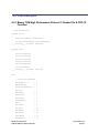
4.4 Code Examples
4.4.1 Binary TCM High Performance Protocol C Header File & CRC-16
Function
// type declarations
typedef struct
{
UInt8 pollingMode, flushFilter;
Float32 sensorAcqTime, intervalRespTime;
} __attribute__ ((packed)) AcqParams;
typedef struct
{
Float32 stdDevErr;
Float32 xCoverage;
Float32 yCoverage;
Float32 zCoverage;
Float32 magBearth;
Float32 reserve1;
} __attribute__ ((packed)) CalScore;
enum
{
// Frame IDs (Commands)
kGetModInfo = 1,
// 1
kModInfoResp,
// 2
kSetDataComponents,
// 3
kGetData,
// 4
kDataResp,
// 5
kSetConfig,
// 6
kGetConfig,
// 7
kConfigResp,
// 8
kSave,
// 9
kStartCal,
// 10
kStopCal,
// 11
kSetParam,
// 12
kGetParam,
// 13
kParamResp,
// 14
kPowerDown,
// 15
PNI Sensor Corporation
TCM3 & TCM5 User Manual- Sept 2011
Doc #1007537 r12
Page 44
kSaveDone,
// 16
kUserCalSampCount,
// 17
kUserCalScore,
// 18
kSetConfigDone,
// 19
kSetParamDone,
// 20
kStartIntervalMode,
// 21
kStopIntervalMode,
// 22
kPowerUp,
// 23
kSetAcqParams,
// 24
kGetAcqParams,
// 25
kAcqParamsDone,
// 26
kAcqParamsResp,
// 27
kPowerDoneDown,
// 28
kFactoryUserCal,
// 29
kFactoryUserCalDone, // 30
kTakeUserCalSample,
// 31
// Param IDs
kFIRConfig = 1,
// 3-AxisID(UInt8)+Count(UInt8)+Value(Float64)+...
// Data Component IDs
kHeading = 5,
// 5 - type Float32
kTemperature = 7,
// 7 - type Float32
kDistortion = 8,
// 8 - type boolean
kPCalibrated = 21,
// 21 - type Float32
kRCalibrated,
// 22 - type Float32
kIZCalibrated,
// 23 - type Float32
kPAngle,
// 24 - type Float32
kRAngle,
// 25 - type Float32
kXAligned = 27,
// 27 - type Float32
kYAligned,
// 28 - type Float32
kZAligned,
// 29 - type Float32
// Configuration Parameter IDs
kDeclination = 1,
// 1 - type Float32
kTrueNorth,
// 2 - type boolean
kMountingRef = 10,
// 10 - type UInt8
kUserCalStableCheck,
// 11 - type boolean
kUserCalNumPoints,
// 12 - type UInt32
kUserCalAutoSampling, // 13 – type boolean
PNI Sensor Corporation
TCM3 & TCM5 User Manual – Sept 2012
Doc #1007537 r12
Page 45
kBaudRate,
// 14 – UInt8
// Mounting Reference IDs
kMountedStandard = 1, // 1
kMountedXUp,
// 2
kMountedYUp,
// 3
kMountedStdPlus90,
// 4
kMountedStdPlus180,
// 5
kMountedStdPlus270,
// 6
// Result IDs
kErrNone = 0,
// 0
kErrSave,
// 1
};
// function to calculate CRC-16
UInt16 CRC(void * data, UInt32 len)
{
UInt8 * dataPtr = (UInt8 *)data;
UInt32 index = 0;
// Update the CRC for transmitted and received data using
// the CCITT 16bit algorithm (X^16 + X^12 + X^5 + 1).
UInt16 crc = 0;
while(len--)
{
crc = (unsigned char)(crc >> 8) | (crc << 8);
crc ^= dataPtr[index++];
crc ^= (unsigned char)(crc & 0xff) >> 4;
crc ^= (crc << 8) << 4;
crc ^= ((crc & 0xff) << 4) << 1;
}
return crc;
}
PNI Sensor Corporation
TCM3 & TCM5 User Manual- Sept 2011
Doc #1007537 r12
Page 46
4.4.2 Binary TCM Protocol C++ Communication Examples
The following 4 example files, CommProtocol.h, CommProtocol.cp, TCM5.h and TCM5.cp would be used
together for proper communication with a TCM3, TCM5 or TCM5L module.
NOTE:
The follwing files are not included in the samples code:
SystemSenPort.h; Processes.h,
TickGenerator.h.
4.4.2.1 CommProtocol.h File:
#pragma once
#include "SystemSerPort.h"
#include "Processes.h"
//
//
This
file
contains
objects
used
to
handle
the
serial
communication
with
the
unit.
Unfortunately, these files are not available as the program was written on a non-PC computer.
The comments in the code should explain what is expected to be sent or received from these
functions so that you can write this section for your specific platform.
For example, with the
TickGenerator.h, you would need to write a routing that generates 10msec ticks.
//
//
//
CommHandler is a base class that provides a callback for incoming messages.
//
class CommHandler
{
public:
// Call back to be implemented in derived class.
virtual void HandleComm(UInt8 frameType, void * dataPtr = NULL, UInt16 dataLen = 0) {}
};
//
//
CommProtocol handles the actual serial communication with the unit.
//
Process is a base class that provides CommProtocol with cooperative parallel processing.
Control method will be
//
called by a process manager on a continuous basis.
//
class CommProtocol : public Process
{
public:
enum
{
PNI Sensor Corporation
TCM3 & TCM5 User Manual – Sept 2012
Doc #1007537 r12
Page 47
The
// Frame IDs (Commands)
kGetModInfo = 1,
// 1
kModInfoResp,
// 2
kSetDataComponents,
// 3
kGetData,
// 4
kDataResp,
// 5
// Data Component IDs
kHeading = 5,
// 5 - type Float32
kTemperature = 7,
// 7 - type Float32
kPCalibrated = 21,
// 21 - type Float32
kRCalibrated,
// 22 - type Float32
kIZCalibrated,
// 23 - type Float32
kPAngle,
// 24 - type Float32
kRAngle,
// 25 - type Float32
kBufferSize = 512,
// maximum size of our input buffer
kPacketMinSize = 5
// minimum size of a serial packet
};
enum
{
};
// SerPort is a serial communication object abstracting the hardware implementation
CommProtocol(CommHandler * handler = NULL, SerPort * serPort = NULL);
void Init(UInt32 baud = 38400);
void SendData(UInt8 frame, void * dataPtr = NULL, UInt32 len = 0);
void SetBaud(UInt32 baud);
protected:
CommHandler * mHandler;
SerPort * mSerialPort;
UInt8 mOutData[kBufferSize], mInData[kBufferSize];
UInt16 mExpectedLen;
UInt32 mOutLen, mOldInLen, mTime, mStep;
UInt16 CRC(void * data, UInt32 len);
void Control();
};
PNI Sensor Corporation
TCM3 & TCM5 User Manual- Sept 2011
Doc #1007537 r12
Page 48
PNI Sensor Corporation
TCM3 & TCM5 User Manual – Sept 2012
Doc #1007537 r12
Page 49
4.4.2.2 CommProtocol.cp File:
#include "CommProtocol.h"
// import an object that will provide a 10mSec tick count through a function called Ticks()
#include "TickGenerator.h"
//
//
SerPort is an object that controls the physical serial interface.
It handles sending out
//
the characters, and buffers the characters read in until we are ready for them.
//
CommProtocol::CommProtocol(CommHandler * handler, SerPort * serPort)
: Process("CommProtocol")
{
mHandler = handler;
// store the object that will parse the data when it
is fully received
mSerialPort = serPort;
Init();
}
//
//
Initialize the serial port and variables that will control this process
//
void CommProtocol::Init(UInt32 baud)
{
SetBaud(baud);
mOldInLen = 0;
// no data previously received
mStep = 1;
// goto the first step of our process
}
//
//
Put together the frame to send to the unit
//
void CommProtocol::SendData(UInt8 frameType, void * dataPtr, UInt32 len)
{
UInt8 * data = (UInt8 *)dataPtr;
// the data to send
UInt32 index = 0;
// our location in the frame we are putting together
UInt16 crc;
// the CRC to add to the end of the packet
UInt16 count;
// the total length the packet will be
count = (UInt16)len + kPacketMinSize;
// exit without sending if there is too much data to fit inside our packet
if(len > kBufferSize - kPacketMinSize) return;
PNI Sensor Corporation
TCM3 & TCM5 User Manual- Sept 2011
Doc #1007537 r12
Page 50
// Store the total len of the packet including the len bytes (2), the frame ID (1),
// the data (len), and the crc (2).
If no data is sent, the min len is 5
mOutData[index++] = count >> 8;
mOutData[index++] = count & 0xFF;
// store the frame ID
mOutData[index++] = frameType ;
// copy the data to be sent
while(len--) mOutData[index++] = *data++;
// compute and add the crc
crc = CRC(mOutData, index);
mOutData[index++] = crc >> 8 ;
mOutData[index++] = crc & 0xFF ;
// Write block will copy and send the data out the serial port
mSerialPort->WriteBlock(mOutData, index);
}
//
//
Call the functions in serial port necessary to change the baud rate
//
void CommProtocol::SetBaud(UInt32 baud)
{
mSerialPort->SetBaudRate(baud);
mSerialPort->InClear();
// clear any data that was already waiting in the
buffer
}
//
// Update the CRC for transmitted and received data using the CCITT 16bit algorithm (X^16 + X^12
+ X^5 + 1).
//
UInt16 CommProtocol::CRC(void * data, UInt32 len)
{
UInt8 * dataPtr = (UInt8 *)data;
UInt32 index = 0;
UInt16 crc = 0;
while(len--)
{
crc = (unsigned char)(crc >> 8) | (crc << 8);
crc ^= dataPtr[index++];
crc ^= (unsigned char)(crc & 0xff) >> 4;
PNI Sensor Corporation
TCM3 & TCM5 User Manual – Sept 2012
Doc #1007537 r12
Page 51
crc ^= (crc << 8) << 4;
crc ^= ((crc & 0xff) << 4) << 1;
}
return crc;
}
//
//
This is called each time this process gets a turn to execute.
//
void CommProtocol::Control()
{
// InLen returns the number of bytes in the input buffer of the serial object that are
available
// for us to read.
UInt32 inLen = mSerialPort->InLen();
switch(mStep)
{
case 1:
{
// wait for length bytes to be received by the serial object
if(inLen >= 2)
{
// Read block will return the number of requested (or available) bytes that
are in the
// serial objects input buffer.
// read the byte count
mSerialPort->ReadBlock(mInData, 2);
//
byte
count
is
ALWAYS
transmitted
in
big
endian,
copy
byte
count
mExpectedLen to
// native endianess
mExpectedLen = (mInData[0] << 8) | mInData[1];
// Ticks is a timer function.
1 tick = 10msec.
// wait up to 1/2s for the complete frame (mExpectedLen) to be received
mTime = Ticks() + 50 ;
mStep++ ;
// goto the next step in the process
}
break ;
}
case 2:
{
// wait for msg complete or timeout
if(inLen >= mExpectedLen - 2)
{
PNI Sensor Corporation
TCM3 & TCM5 User Manual- Sept 2011
Doc #1007537 r12
Page 52
to
UInt16 crc, crcReceived;
// calculated and received crcs.
// Read block will return the number of requested (or available) bytes that
are in the
// serial objects input buffer.
mSerialPort->ReadBlock(&mInData[2], mExpectedLen - 2);
// in CRC verification, don't include the CRC in the recalculation (-2)
crc = CRC(mInData, mExpectedLen - 2);
// CRC is also ALWAYS transmitted in big endian
crcReceived = (mInData[mExpectedLen - 2] << 8) | mInData[mExpectedLen - 1] ;
if(crc == crcReceived)
{
// the crc is correct, so pass the frame up for processing.
if(mHandler) mHandler->HandleComm(mInData[2], &mInData[3], mExpectedLen
- kPacketMinSize);
}
else
{
// crc's don't match so clear everything that is currently in the input
buffer since
// the data is not reliable.
mSerialPort->InClear();
}
// go back to looking for the length bytes.
mStep = 1 ;
}
else
{
// Ticks is a timer function.
1 tick = 10msec.
if(Ticks() > mTime)
{
// Corrupted message. We did not get the length we were expecting within
1/2sec of receiving
// the length bytes. Clear everything in the input buffer since the data
is unreliable
mSerialPort->InClear();
mStep = 1 ;
// Look for the next length bytes
}
}
break ;
}
default:
break ;
}
PNI Sensor Corporation
TCM3 & TCM5 User Manual – Sept 2012
Doc #1007537 r12
Page 53
}
PNI Sensor Corporation
TCM3 & TCM5 User Manual- Sept 2011
Doc #1007537 r12
Page 54
4.4.2.3 TCM5.h File (For TCM3, TCM5 and TCM5L Modules):
#pragma once
#include "Processes.h"
#include "CommProtocol.h"
//
//
This file contains the object providing communication to the TCM.
It will set up the unit
and parse packets received
//
Process is a base class that provides TCM with cooperative parallel processing.
The Control
method will be
//
called by a process manager on a continuous basis.
//
class TCM : public Process, public CommHandler
{
public:
TCM(SerPort * serPort);
~TCM();
protected:
CommProtocol * mComm;
UInt32 mStep, mTime, mResponseTime;
void HandleComm(UInt8 frameType, void * dataPtr = NULL, UInt16 dataLen = 0);
void SendComm(UInt8 frameType, void * dataPtr = NULL, UInt16 dataLen = 0);
void Control();
};
PNI Sensor Corporation
TCM3 & TCM5 User Manual – Sept 2012
Doc #1007537 r12
Page 55
4.4.2.4 TCM5.cp File (For TCM3, TCM5 & TCM5L Modules):
#include "TCM.h"
#include "TickGenerator.h"
const UInt8 kDataCount = 4;
// We will be requesting 4 componets (Heading, pitch, roll,
temperature)
//
//
This object polls the TCM unit once a second for heading, pitch, roll and temperature.
//
TCM::TCM(SerPort * serPort)
: Process("TCM")
{
// Let the CommProtocol know this object will handle any serial data returned by the unit
mComm = new CommProtocol(this, serPort);
mTime = 0;
mStep = 1;
}
TCM::~TCM()
{
}
//
//
Called by the CommProtocol object when a frame is completely received
//
void TCM::HandleComm(UInt8 frameType, void * dataPtr, UInt16 dataLen)
{
UInt8 * data = (UInt8 *)dataPtr;
switch(frameType)
{
case CommProtocol::kDataResp:
{
// Parse the data response
UInt8 count = data[0];
// The number of data elements returned
UInt32 pntr = 1;
// Used to retrieve the returned elements
// The data elements we requested
Float32 heading, pitch, roll, temperature;
if(count != kDataCount)
{
// Message is a function that displays a C formatted string (similar to
printf)
PNI Sensor Corporation
TCM3 & TCM5 User Manual- Sept 2011
Doc #1007537 r12
Page 56
Message("Received
%u
data
elements
instead
of
the
%u
requested\r\n",
(UInt16)count,
(UInt16)kDataCount);
return;
}
// loop through and collect the elements
while(count)
{
// The elements are received as {type (ie. kHeading), data}
switch(data[pntr++])
// read the type and go to the first byte of the
data
{
// Only handling the 4 elements we are looking for
case CommProtocol::kHeading:
{
// Move(source, destination, size (bytes)).
Move copies the specified number of
// bytes from the source pointer to the destination pointer.
// Store the heading.
Move(&(data[pntr]), &heading, sizeof(heading));
// increase the pointer to point to the next data element type
pntr += sizeof(heading);
break;
}
case CommProtocol::kPAngle:
{
//
Move(source,
destination,
size
(bytes)).
Move
copies
the
specified number of
// bytes from the source pointer to the destination pointer.
// Store the pitch.
Move(&(data[pntr]), &pitch, sizeof(pitch));
// increase the pointer to point to the next data element type
pntr += sizeof(pitch);
break;
}
case CommProtocol::kRAngle:
{
//
Move(source,
destination,
size
(bytes)).
Move
copies
specified number of
// bytes from the source pointer to the destination pointer.
// Store the roll.
Move(&(data[pntr]), &roll, sizeof(roll));
PNI Sensor Corporation
TCM3 & TCM5 User Manual – Sept 2012
Doc #1007537 r12
Page 57
the
// increase the pointer to point to the next data element type
pntr += sizeof(roll);
break;
}
case CommProtocol::kTemperature:
{
//
Move(source,
destination,
size
(bytes)).
Move
copies
the
specified number of
// bytes from the source pointer to the destination pointer.
// Store the heading.
Move(&(data[pntr]), &temperature, sizeof(temperature));
// increase the pointer to point to the next data element type
pntr += sizeof(temperature);
break;
}
default:
// Message is a function that displays a formatted string (similar
to printf)
Message("Unknown type: %02X\r\n", data[pntr - 1]);
// unknown data type, so size is unknown, so skip everything
return;
break;
}
count--;
// One less element to read in
}
// Message is a function that displays a formatted string (similar to printf)
Message("Heading: %f, Pitch: %f, Roll: %f, Temperature: %f\r\n", heading, pitch,
roll,
temperature);
mStep--;
// send next data request
break;
}
default:
{
// Message is a function that displays a formatted string (similar to printf)
Message("Unknown frame %02X received\r\n", (UInt16)frameType);
break;
}
}
}
PNI Sensor Corporation
TCM3 & TCM5 User Manual- Sept 2011
Doc #1007537 r12
Page 58
//
//
Have the CommProtocol build and send the frame to the unit.
//
void TCM::SendComm(UInt8 frameType, void * dataPtr, UInt16 dataLen)
{
if(mComm) mComm->SendData(frameType, dataPtr, dataLen);
// Ticks is a timer function.
1 tick = 10msec.
mResponseTime = Ticks() + 300;
// Expect a response within 3 seconds
}
//
//
This is called each time this process gets a turn to execute.
//
void TCM::Control()
{
switch(mStep)
{
case 1:
{
UInt8 pkt[kDataCount + 1];
// the compents we are requesting, preceded by the
number of...
// ...components being requested
pkt[0] = kDataCount;
pkt[1] = CommProtocol::kHeading;
pkt[2] = CommProtocol::kPAngle;
pkt[3] = CommProtocol::kRAngle;
pkt[4] = CommProtocol::kTemperature;
SendComm(CommProtocol::kSetDataComponents, pkt, kDataCount + 1);
// Ticks is a timer function.
1 tick = 10msec.
mTime = Ticks() + 100;
// Taking a sample in 1s.
mStep++;
// go to next step of process
break;
}
case 2:
{
// Ticks is a timer function.
1 tick = 10msec.
if(Ticks() > mTime)
{
// tell the unit to take a sample
SendComm(CommProtocol::kGetData);
mTime = Ticks() + 100;
// take a sample every second
mStep++;
}
PNI Sensor Corporation
TCM3 & TCM5 User Manual – Sept 2012
Doc #1007537 r12
Page 59
break;
}
case 3:
{
// Ticks is a timer function.
1 tick = 10msec.
if(Ticks() > mResponseTime)
{
Message("No response from the unit.
Check connection and try again\r\n");
mStep = 0;
}
break;
}
default:
break;
}
}
PNI Sensor Corporation
TCM3 & TCM5 User Manual- Sept 2011
Doc #1007537 r12
Page 60