1
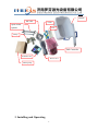
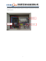
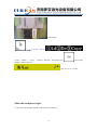
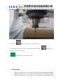
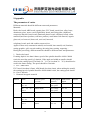
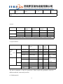
CNC Router user manual Jinan Ruofen Laser Machinery Co.,Ltd Website: www.ruofencnc.com Service Contact information : Email: [email protected] Skype: lifancnc Please send us your Order No. , we will do our best service for you. Customer First Service First Quality First Contents 1. Foreword---------------------------------------------------------------------2 2. Part names and function------------------------------------------- -------3 3. Installing and Operating-------------------------------------------- ------5 4. Maintenance---------------------------------------------------------------14 5. Caution--------------------------------------------------------------- -----15 6. High-speed woodworking CNC Router -----------------------------15 7. Electrical appliance-------------------------------------------------------16 8. Tips--------------------------------------------------------------------------17 9. Appendix-------------------------------------------------------------------18 1 1. Foreword Thank you for purchasing our CNC router! We professionally manufacture of CNC Router in China. The routers are used for woodworking, advertising (manufacturing signs, marks and decoration), furniture, mould and crafts. In the Introduction describe the Installation and maintenance, analyze of the normal malfunctions, simple engraving techniques in detail. CNC Router is of high precision machine. Inaccurate installation and operation would affect the precision, stability and working lifetime. Please peruse the Introduction in order to correctly operation and maintenance. Keep the safety. Please keep the user’s manual for further use. 1. To ensure correct and safe usage with a full understanding of this product's performance, please be sure to read through this manual completely and store it in a safe location. 2. The contents of this operation manual and the specifications of this product are subject to change without notice. 3. The operation manual and the product have been prepared and tested . If you find any misprint or error, please inform us. 2. Parts and functions Accessories of CNC router 2 Standard parts Please check the number of the following parts. Please contact with us if any item is omitted. Item Name 1 Wood Tool Box 2 Collet(1.5kw spindle no 12.7Φ ) 3 4 5 6 7 8 9 10 11 12 13 Specification 3.175 Φ 4Φ 6Φ 12.7Φ DSP Controller IDE cable of DSP Controller Hexagon ring spanner Open-ended spanner DSP Installing CD User’s Manual Warranty Card Bucket Power Cord Clamp Water Pump 1.5m 3 Quantity 1box 4pcs 1pc 1pc 0pc 2pcs 1pc 1book 1pc 1pc 1pc 6pc 1pc Remarks Bucket IDE cable Collet Open-ended spanner Tool Clamp DSP Controller Software CD Power cord Water pump 3. Installing and Operating 4 1) connect the power First from the circuit breaker output three firing line ,one null line ,one ground line .and connect to machine .as picture : Null line Ground line Firing line 5 Null line 2). DSP NK105 operating Basic Configuration of NK105 System 6 Firing line Memory: 128M Flash: 256M Monitor: 128 × 64 graphic LCD module 1. Install machine :machine most already contact good,.you only need install DSP to control box,so picture: DSP Cable U disk 2. After install complete ,open power switch . Green ---switch button Red ------scram button Switch Emergency stop 3. DSP screen button function Override+ Increase of feedrate override; input of number 7; increase of spindle gear with the help of auxiliary key when spindle port has input 7 Y+ Positive shift of Y axis; input of number 8; switch between MCS and WCS with the help of auxiliary key Z+ Positive shift of Z axis; input of number 9 X- Negative shift of X axis; input of number 4; returning to mechanical origin with the help of auxiliary key Spindle start/stop Start or stop of spindle under manual mode; input of number 5; backing to workpiece origin with the help of auxiliary key (0,0) X+ Override- 0 Positive shift of X axis; input of number 6 Decrease of feedrate override; input of number 1; decrease of spindle gear with the help of auxiliary key when spindle port has input Y- Negative shift of Y axis; input of number 2 Z- Negative shift of Z axis; input of number 3 Speed switchover Switch between manual high/low speed; input of number 0; tool presetting with the help of auxiliary key Backing to origin Backing to origin of X and Y axes; input of minus; backing to origin of Z axis with the help of auxiliary key Menu Entering menu page; input of decimal point; entering image update page at the time of system start-up 8 Start Up Stop processing; cancellation of various selections, inputs and operations Shift Auxiliary key Down Down direction key Entering manual high/low speed adjustment page under menu page; confirmation of various selections, inputs and operations Increase of spindle gear + Switch between WCS and MCS + Backing to mechanical origin + + Suspend processing; up direction key ESC OK + Start key; breakpoint resuming with the help of auxiliary key Backing to workpiece origin (0,0) Decrease of spindle gear 9 + 0 + + + Floating presetting Z clear Breakpoint resuming Entering help page 4. System Start-up Press : Machine Z X Y backing to mechanical origin. First time you can point ,check relevant parameter. 10 Main parameter : Oper Param 1. G00 speed: 8000mm/min (travelling speed) 2. Gxx speed: 5000mm/min (working speed) 3.Back REF first: no (Mfr param) Password (33587550) 2 (axis outpdir) moving 1. X Positive 2. Y Positive 3. Z Positive (according to machine direction change ) 3 (pulse equivalent) X :0.0098125 Y : 0.0098125 Z: 0.00625 X:0.01128375 Y: 0.01128375 Z: 0.00625 X:0.0115724 Y:0.0115724 4 (Machine strok) 1.strkupperlmt : X 1300 Y 2500 2.strklowerlmt: 5(spindle set) Z 0.00625 X0 Y0 3. Initial gear --change 7 11 Z Z0 --200 (normal straight rack box ) (casting straight rack box ) (normal helical rack box ) (for example :1325) Load the file install U disk 2 (Browse U disk file) 1.load 2.delete 3. Copy , choose 1 load life , then must press , show right number on file, as picture, Then press ok, file is loaded . Make the workpiece origin : 1) first move the machine spindle to left bottom of workpiece . 12 2) Then press , x and y axis clear 0 , x and y origin is ok 3) Sharp of the tool touch the surface of workpiece .then press shift + , z axis clear 0 , z axis origin is ok . As above picture . 4) press this button , machine start to work. 4. Maintenance i The new machines have the wear-in period. We should adjust the machine during this period. One week later, we should check the conjunction of the parts. The main parts are as follows: The conjunction of the side board and 13 the beam, the conjunction of the soleplate and the side board, the coupler between the stepper motor and the Y axis ball screw, the fixed screw in the front of the ball screw. Fixed Screw Side Board Linear Soleplate Fixed Screw ii Maintenance after use. ⑴ Clear the machine after use. ⑵ Filling oil after cleaning. Motor Coupler Side Board Linear Y-axis Orbit (oil point) Soleplate X-axis Ball Screw (fixed ball screw) X-axis Orbit (oil point) iii Remarks: Different material and condition, the period of maintenance are different. Such as: HD board, we should clear it in 3 days. Wood, we should clean it in 7 days. The main points as follows: Y-axis Motor Y-axis Ball Screw (oil point) Side Board Water Cooling Motor ¤ CAUTION ¤ 5. Caution 1. Don’t use un-rating voltage for Xinhuiyou C and Z series CNC routers. 2. Please operate the machine strictly according to the manufacturing size of CNC router. 3. Forbid high strength, overload work. 4. After the using and the cleaning of the 1218 ball screw machines or larger, the gantry should be stopped in the center of the machine, in order to avoid the 14 spontaneous droop of the ball screw which will influence the concentric degree and the accuracy. 5. When encounter smoking, awful smell, noise and other abnormal situation of the machine, please turn off the machine and check it. 6. Make sure the machine connect with the ground wire. 7. Don’t touch the tip of the blade. 8. Don’t use causticity liquid to clean parts and the keyboard of the machine. 9. Different materials and cuttings, choose different cutters and speed. 10. Turn on the spindle motor before positioning the Z axis and cutting mode. 11. Before using of the machine, please check the water circulation to ensure the spindle work well. 12. Don’t damage or change the original wire, don’t pull it, bind it or press it. 13. Don’t touch the cutter and spindle by hand while working. 14. Don’t drop the liquid and metallic parts to the machine. After using, lubricate the ball screw, feed shaft, orbit and rack. 15. Working temperature: 0ºC-45ºC 16. Cover the bullet while working to prevent the dust drop into the water and block the spindle. 6. High-speed CNC router The high-speed CNC router is driven by the gear wheel of the X and Y axis, which integrate the validity, speed, capacity. The gear belongs to the manufactured parts, it needs to run in period which to fill the gap between the gear wheel. After the running, we should adjust the machine. The methods are as follows: 1. Turn off the cover of the side plate and main spindle. 2. Use hexagon ring spanner to loose the fixed screw of the driven box. 3. Pull the driven box in the direction of the picture till there is no gap. Don’t use heavy thing to knock the driven box. 4. After adjusting, screw down the fixed ball of the driven box, then turn on the power, after running the machine and make sure there is no mistake, assemble the machine head cover and the side board cover. Maintenance: 1. Clean the orbit, gear wheel, ball screw periodically. 2. Use butter and normal machine oil for the gear wheel and gear axis in proportion of 3:2. 3. The gear wheel needs to be cleaned and lubricate it periodically to avoid rusty. 15 4. Check the tightness of synchronous belt and adjust it in time. X-axis Beam Fixed Screw Driving Box Fixed Screw Ball Screw Driving Box High Speed Direction 7. Electronic Parts. The map of electronic parts of CNC router. Pic.6 Maintenance of electronic parts: 1. Clean the motor and the dust in the control box to heat emission. 2. Check the wire, such as: knot, twist and abrasion. Emergency Stop Main Switch Filter Frequency Converter Transformer Driver Water Cooling Spindle Stepper Motor Stepper Motor Stepper Motor Analysis of normal malfunction and maintenance Fault Arise the phenomenon of disturb, lost step, in the cutting process Fault Reason Remove The Fault Spider coupler loose Screw down the spider couplers The driver lost step Change the controller The numerical card loose Insert the numerical card firmly Arise the phenomenon of rack wave etc when the cutting process Loosen of fixed screw of the ball Adjust the concentricity then screw or the guide block lead to the screw down the screw. decrease of the accuracy; adjust the concentricity then screw down the screw. When turn on the machine, the spindle motor moves to one direction or noisy, turn off the machine. The wire breaks inside when running or the loose of the jointing point. 16 Use the gauge to check where the disconnection point is, then change the wire. When the machine is There is dust in the ball screw or the Discharge the bearing and clean running the driven lacking of the oil. it or change, then add oil and system arise noise and assemble. have the phenomenon to be block. The limit switch lost the function or the screen show the limit alarm in a long time. The limit switch broken or the switch Change the switch, check the wire breaks inside or the inside of the circuitry, and turn off the switch stick, the emergency stop is on. emergency stop. 8.Tips Wood cutting Wood is the main important material of modern decorations. There are many new designs of wood cuttings. Different materials, the cutting method is also different. The following is the introduction of different materials. 1. If the wood is soft and more flexible adopt to cut the wood-wool in landscape orientation, the speed of the cutting should be faster gradually. 2. If the wood material is hard and the texture is too tight, pay attention to the speed of the cutter going into the material. First it should be slowly, after it cuts a gap in the material, and then add the speed. Steel cutting Hardness of steel is several times than wood. The following is the introduction of steel cutting. 1. Choose the special cutter for steel. 2. In the process of cutting adjust of the cutting speed and add cooling oil to the cutter. 3. If the depth of the material is too thick, we should cut it layer by layer. Stone cutting: The inner structure of the stone is high intensity not uniform. Stone belongs to the material which the intensity of the inside structure is not uniform. Due to hard intensity of the stone, the requirement of the cutter is high; besides, the stone cutting also has the requirement to the rotation speed of the spindle motor. When cutting the stone, please choose the wearable alloy cutter with high intensity, and pay attention to the cooling of the cutter and the spindle. The above introduction only for reference, please operate according to the actual situation. 17 9.Appendix The parameter of cutter Different materials should be different cutter and parameters. Materials: Dual-color board, ABS board, organic glass, PVC board, metal (iron, alloy, brass, aluminum), glass, stone, wood, high density board, anti-firing plate, chipboard, composite material (brass board, aluminum plastic board, colophony board, soften material (hard latex products, soft latex product), small name seal material, organic glass seal, ox horn seal, brass seal, steel seal, latexseal, colophony board, stock ink cushion, atom seal etc. Applied: chest card, construction mould, steel mould, letter mould, seal, furniture, cutting graphics, gift, souvenir making, adverting letter cutting, engraving… During the processing, different materials should be different cutter and parameters. 1. Dual-color board If cutting depth is less than 0.8mm, speed of the spindle should be 10000~20000 r/min; the traveling speed is 2.4m/min. If the angle and width are smaller should decrease the cutting speed. The blade 30 ゜/0.3 (or less than 30 ゜/0.3) should not be used in the frame cutting. The speed should be 0.6m/min. 2. PVC, ABS board PVC board (less than 0.5mm), ABS board (less than 1mm), when making the mould, the rotating speed of spindle should be 20000-40000 r/min, the cutting speed should be 1.2m~2.4m/min. 3. Nonmetal inorganic material Material Blade Rotation Speed (rev/min) Cutting Speed (m/min) Blade Down Speed Marble 20 ゜~30 ゜ /0.1~0.3 20000~40000 0.3 average low speed 0.2~0.4 20 ゜~30 ゜/0.3 above 20000~40000 0.3 average low speed 0.3~0.4 40 ゜ above 20000~40000 0.6 0.3~ 0.5 20 ゜~30 ゜ /0.1~0.3 20000~40000 0.3 0.1-0.2 20 ゜~30 ゜/0.3 above 20000~40000 40000 0.3 0.6~2.4 0.1~0.4 0.1 Glass 18 Remarks 40 ゜ above/0.3 above 20000~40000 40000 0.3 0.6~2.4 0.1~0.4 0.1 For stone cutting please take the above parameters for reference, the harder stones should deduce the speed. 4. Wood Material Cutter Rotate Speed (r/min) Cut Speed (m/min) Travel Speed (m/min) Engrave 200-300/0.1-0.3 20000-40000 0.8-2.4 0.5-2 300 /0.3 20000-40000 1.2-2.4 1-3 φ8-φ13 10000-20000 0.3 1-3 φ8 10000-20000 0.3 3-8 Cut Remarks Different material, density sheet or fireproofing sheet, adjust the parameter of cutter and blade. 5. Organic Material Material Organic glass Ox horn stamp Engrave Hard plastic Engrave Cutter Rotate (r/min) 200-300/0.1-0.3 Cut speed (m/min) Travel Speed (m/min) 10000-40000 0.6-0.8 0.2-0.8 30 /0.3 10000-40000 0.8-2.4 1-3 φ0.8-φ1.3 10000-40000 0.3 1-3 φ2.5-φ3 20000-40000 0.3 5-10 Big motor 200-300/0.3-0.5 10000-20000 0.6-1.6 0.3-0.1 30 /0.5 10000-20000 2.4 0.5-1 Please use the water cooling system φ0.8-φ1.3 10000-20000 0.6-1.6 0.5-1 φ1.5 0 Cut 0 Cut Soft material speed 10000-20000 0.8-1.6 0.5-2 0 40000 0.3-0.6 1-20 40 /0.3 40000 0.6-1.2 1-20 0 20 -30 /0.3 0 Remarks power The above parameter is only for preference. Please adjust the parameter accord to different material, cutter and precision. (1) Hard material 19 If the cutter is small and the material is hard, deduce the depth of cutter on the clamp and deduce the cutting speed. If it needs the big depth for the cutter, deduce the speed of spindle. If you need the high light degree for your products, deduce of cutter on the clamp, improve the speed of spindle, improve the cutting speed and add the superposition. (2) Soft material If it needs the high light degree for your products, please improve the speed of spindle and deduce the cutting speed and add the superposition under the material not insert the cutter. The parameter isn’t absolute, please adjust the parameter accord to the your condition. You will find your favorable parameter. So it can reach to the best efficiency under the good precision and quality. Please take care the abrasion of cutter when engraving the material. The abrasion of cutter will affect the effect. 20