1
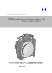
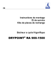
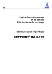
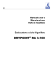
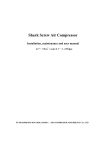
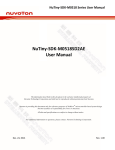
Compressor
Ningbo Xinda “S” Series Fixed Oil Spray Screw Compressor
User’s Manual
(Please read this manual thoroughly before use)
NO.CN03SF
Ningbo Xinda
Table of Contents
Preface… … … … … … … … … … … … … … … … … … … … … … … … … … … … … … … … … .… … 1
Chapter I
Safety Precautions… … … … … … … … … … … … … … … … … … … … … … … .… ..2
Chapter II
Installation Standards and Requirements… … … … … … … … … … … … … … … … 3
Chapter III
Performance Parameters and Apparent Dimension of the Unit… … … … … … … ..6
Chapter IV
Flow Process and Functions of the Compressor System...… … … … … … … … .… 8
Chapter V
Electrical Control System..… … … … … … … … … … … … … … … … … … … … … 12
Chapter VI
Operating Guide… … … … … … … … … … … … … … … … … … … … … … … … … .14
Chapter VII
Maintenance… … … … … … … … … … … … … … … … … … … … … … … … … … … 16
Chapter VIIII Common Faults and Solutions… … … … … … … … … … … … … … … … … … … … 20
Enclosure: Warranty Card
Enclosure: Memorandum
Ningbo Xinda
Preface
Dear User, thank you very much for buying Ningbo Xinda “S” series products. We
sincerely hope that you can feedback the information related with the product use to
us so that we can provide more satisfactory services to our customers, as your
expectation is our objective.
This Manual provides an overall description about the correct methods and related
precautions for the installation, operation and maintenance of Xinda screw
compressors. In order to ensure that the compressor can operate economically and
optimally with high safety, and increase its service life to the greatest extent, please
read this manual carefully before use, to understand its basic construction, operating
principles and standard operation and strictly observe relevant safety regulations. The
operators should have this manual in hand.
This series of products is designed according to the compressor standards JB/T6430
and have been tested strictly in its operation before the products leave the factory. Its
performance test is carried out according to the national standards GB/T3853-1998
eqv ISO1217 1996, and its performance meets the optimal design requirements. The
maintenance must be carried out by qualified personnel. Please contact us for further
information (See the back cover).
Note: This manual is applicable to following types:
SF45, SF55, SF75, SF90, SF110 and SF132 series of products
As the product is improved and updated, our company has right to modify
this manual without notice.
Important: the consequences resulted from violation of the instructions in
this manual shall not be covered in the warranty services of our company.
Copyright reserved. This manual must not be reprinted, or otherwise related
legal responsibility should be affixed for.
NO. CN03SF
China Ningbo Xinda Screw Compressor Co., Ltd.
Ningbo Xinda
Chapter I Safety Precautions
The air, oil and electricity inside the compressor can cause dangers. Please enhance safety
consciousness, ensure safe operation and carry out inspection and maintenance correctly, in order
to prevent dangers and faults.
The products of this series are not designed to operate under water and in other enclosed rooms.
Therefore, their use in these applications is strictly prohibited, in order to avoid serious dangers or
accidents. If the product is used as the equipment for producing the air for human breath, it is
necessary to fully purify the air according to local standards and regulations in order to meet the
breathing standard and prevent pollution to the atmosphere and the air for human breath.
Main Safety Precautions:
1. Do not start any inspection or maintenance work until the power supply is turned off and the
air in the whole compressor system has been discharged completely (internal pressure in the
unit is equal to the atmospheric pressure).
2. Before start up, by turning on the power supply for a short moment (about one second),
check whether the compressor rotates in correct direction. Or otherwise the screw assembly of
the compressor will be damaged within a few seconds.
3. Ensure that clean gas is absorbed into the machine during its operation, and there is no
flammable, explosive or toxic gas.
4. Before the unit operation, it is necessary to ensure that all the connectors and accessories are
tightened firmly.
5. Do not loosen or remove any pipe fittings, connectors and components during operation, in
order to prevent serious damage or injury.
6. Air switch, fuser or other safety devices must be installed on the power supply circuit of the
compressor, in order to ensure reliability of electrical equipment. Ensure correct earthing
according to safety regulations of relevant authority.
7. The compressor should not operate at the discharge pressure greater than the value indicated
on its nameplate. Or otherwise the motor will be overloaded and the unit will stop operation.
8. Safety valve is installed on the air-oil separator. When the gas pressure inside the system
exceeds the set pressure, the safety valve will act. In this case, it is necessary to find the
causes and troubleshoot.
9. Do not use corrosive chemical solvents to clean the compressor and auxiliary equipment.
10. The compressor cannot be used directly for producing the air for human breath. If the
compressed air must meet breathing standard, corresponding treatment should be conducted
after purification. Safety measures should be taken for other gas equipment, especially in the
applications that are not mentioned in this manual.
11. During the operation of the unit, the door of the unit casing body should be closed, and this
door can be open for a while only if the unit is checked. However, please pay attention to the
harms caused to human body by moving parts and high-temperature parts, and wear protective
ear cover correctly. Do not leave any objects on or inside the unit.
12. The pressure vessel cannot be repaired or re-welded, and it is prohibited to check the internal
parts of the compressor or pressure vessel using open flame light source.
13. Ensure there is complete sound insulation material on the compressor. Please contact our
company if the material is damaged.
Caution: Before starting up the compressor, related operators must read and understand
this manual, and should contact the service personnel of Xinda Company if they have any
questions. We will provide best services in the possible shortest time. We do not take any
responsibilities for the damages and injuries caused due to neglecting safety precautions or
non-safe operations, even if these precautions or non-safe operation is not mentioned in this
manual.
Chapter II
Installation Standards and Requirements
1. Requirements for Arrangement in Installation Place
(1) Compressor house should be as near to load center as possible, in order to reduce pipe length,
pressure loss and power consumption and ensure air supply pressure.
(2) Scientific supply of electrical power, water supply and ventilation should be taken into
account in the house planning.
(3) To suit to the development in the future, space should be reserved on the general drawing for
expansion.
(4) Air compressor suctions air directly from atmosphere. In order to reduce the possible wear,
corrosion and explosion of compressor unit, there must be specified distance between the
compressor house and the place where there is explosive, corrosive, toxic gas or dust or other
harmful substances, and the compressor house should be located on lower side of annual wind
directions occurring at least frequency in aforesaid places, so that the effect of harmful
substances on the house is minimized.
(5) Since the compressor gives out a plenty of heat, especially in summer when high temperature
exists inside the unit, the compressor house should be oriented to the direction in which the
machine is well-ventilated and the sunshine time can be reduced.
(6) Though the compressor is provided with casing, raining on it is strictly prohibited. Hence
compressor should be not mounted outdoors.
(7) Compressor house should be a separate building.
2. Precautions during Handling
(1) In order to ensure safe handling, please pay attention to the total weight of the compressor
unit.
(2) When the unit is handled on a fork, soft gaskets should be used for protecting the unit from
surface damage. The fork teeth should be inserted completely into the compressor base.
(3) When the unit is handled with the help of a crane, balancing should be ensured. The steel wire
rope should be fixed on correct positions and slings should be prepared to prevent the rope
from pressurizing on the compressor casing, or otherwise the casing will get damaged.
(4) Transportation bracket should be installed and the fixtures should be tightened and locked first
when the compressor unit is transported and handled, in order to prevent possible damages to
the compressor, as shown in the figure. After compressor unit is mounted in position, it is
necessary to remove the bracket and fixtures shown in the figure before the compressor is put
into operation!
Bracket for transportation and handling
Fixtures for locking the compressor during transportation and handling
3. Requirements for Compressor House Installation
(1) Sufficient space should be reserved in the installation place for subsequent maintenance and
repair work to be done. The floor had better be finished cement floor and its unevenness
should not be greater than 0.5/1000 (mm), and the floor should be enough hard and firm to
support the weight of the compressor.
(2) The compressor should be placed on horizontal floor, and good joint must be ensured
between the casing bottom and floor surface, in order to prevent vibrations and noises.
(3) If possible, sound absorbing board can be fitted on the walls of compressor house in order to
further reduce the noises. However, the materials with hard surface (such as ceramic tiles)
should not be fitted on the walls.
(4) The recommended minimum spacing from compressor installation position to the front side,
rear side, left side, right side and the top should be greater than 1m.
(5) Since air-cooled compressor is apparently affected by the ambient temperature, the
compressor house should be well-ventilated and dry. An exhaust fan should be mounted in it
and sufficient incoming air volume should be provided, in order to ensure that air flowrate is
lower than 4.5m/s at air inlet window and ambient temperature should be within –5oC~40oC.
The following figure shows compressor ventilation designs:
(6) There is a small quantity of dust and clean air as well as no harmful gases, sulfurous acids and
other corrosive medium in the compressor house.
4. Pipeline Installation Requirements
(1) The air outlet of the compressor unit is provided with threaded connector for connection with
your air supply pipeline. Please refer to Chapter III “Performance Parameters and Apparent
Dimension of the Unit” for installation dimensions.
(2) The branches must be connected from the top of main pipeline in order to avoid condensation
water in the pipes from flowing down into the compressor.
(3) The pipeline should be as short and straight as possible when it is laid around the whole
production building, in order to minimize the number of bends and valves and the pressure
loss. The post treatment system should be provided with maintenance by-pass if possible.
5. Connection and Arrangement of Air Pipeline
(1) Compressed air pipes are connected by welding, but the pipe and equipment or valve should
be connected using corresponding flange or screwed connections. The pipes that are often
removed should be connected using screwed connections if the pipe diameter is less than or
equal to DN 25, and connected using flanges if the pipe diameter is greater than DN 25.
(2) For the pipeline that delivers compressed air that is not dried and purified, the pipeline
generally should be laid at a slope of more than 2/1000, and a blow-off valve (screwed plug)
should be mounted on its low end. The pipeline should be laid as short and straight as possible
and least bends and valves should be used, in order to drain the wastewater in the pipes better.
(3) The top of underground pipeline should be embedded in 0.7m at least under the ground, but
this restriction is not applicable to the pipeline that delivers dry and purified compressed air.
(4) After completion of system installation, air pressure test and air-tightness test should be
carried out, and hydrostatic test should not be carried out. The test pressure is 1.05~1.5 times
the pressure of the same gas, and if no leakage is detected, the pipeline is acceptable.
(5) Air receiver tank is pressure vessel, and all the necessary safety valve, pressure gauge,
blow-off valve and other safety accessories should be mounted correctly and be reported to
local labor authority for records. Annual routine inspection must be carried out every year.
6. Selection of Pipe Size
While gas flows inside the pipeline, it has friction resistance in straight pipes and local resistance
in the valves, tees, bends and reduced pipes, which will cause gas pressure loss. Generally,
pressure drop in a pipe length can be obtained from the data in following table:
Air Flow --- Pipe Pressure Drop kg/cm2 ---(100m)
Air flow
3
Pipe Diameter (inch)
m /min
1 1/2
2
6.5
2.50
0.709
7.0
2.90
7.5
2 1/2
3
3 1/2
4
5
0.187
0.0744
0.0346
0.815
0.217
0.0863
0.0401
3.33
0.940
0.249
0.0990
0.0460
8.0
3.79
1.0
0.283
0.113
0.0524
0.0247
8.5
4.28
1.21
0.319
0.127
0.0590
0.0309
9.0
4.80
1.35
0.359
0.143
0.0662
0.0347
9.5
5.35
1.51
0.399
0.159
0.0738
0.0386
10
5.93
1.67
0.442
0.176
0.0818
0.0428
12
8.53
2.40
0.637
0.254
0.118
0.0616
0.0196
14
11.6
3.27
0.866
0.345
0.160
0.0839
0.0260
Air flow
Pipe Diameter (inch)
3
m /min
2
2 1/2
3
3 1/2
4
5
15
3.76
0.995
0.396
0.184
0.0963
0.0306
16
4.28
1.13
0.450
0.209
0.110
0.0348
18
5.41
1.14
0.570
0.265
0.139
0.0441
0.0177
20
6.68
1.77
0.704
0.327
0.171
0.0544
0.0219
22
8.08
2.14
0.851
0.396
0.209
0.0659
0.0265
24
9.62
2.55
1.01
0.471
0.246
0.0784
0.0315
28
11.3
2.99
1.19
0.553
0.289
0.0920
0.0370
30
15.0
3.98
1.58
0.736
0.385
0.122
0.0429
35
20.4
5.41
2.16
1.00
0.525
0.167
0.0670
7.08
2.82
1.31
0.618
0.218
0.0876
40
6
Notes:
1. Actual pressure drop in a straight pipe section = gauge value pipe length (100
compression ratio). (Compression ratio = gauge pressure +1);
2. The total pressure drop in the pipeline should include the local pressure losses caused in
the bends, reduced pipes, tees and valves, which can be found in related manuals.
3. After referred to the tables, it is necessary to check whether the pressure loss of
compressed air supplied to the user end is within the permissible range. The experience
shows that total pressure loss should not exceed 0.4kg/cm2 in 100m pipeline length. If it
exceeds this value, the pipe diameter must be increased.
Chapter III Performance Parameters and Apparent Dimension of the Unit
S Type compressor unit is motor-driven immovable oil-spray screw compressor and SF Type unit
is air-cooled compressor. The performance parameters and apparent dimensions of SF45~SF132
are shown in the table below:
Type
Air flow
/Pressure
m3/min/Mpa
A
B
C
D
SF45
SF55
SF75
SF90
SF110
SF132
7.5/0.7
6.6/1.0
5.2/1.3
7.2/0.8
10.2/0.7
8.2/1.0
7.2/1.3
9.5/0.8
13.5/0/7
11.5/1.0
9.5/1.3
12.4/0.8
16.5/0.7
13.7/1.0
11.5/1.3
15.5/0.8
20.0/0/7
17.0/1.0
14.0/1.3
18.5/0.8
23.5/0/7
20.5/1.0
16.6/1.3
22.5/0/8
Cooling method
Drive method
Temperature
Form
Power (Kw)
Rev(r/min)
Motor Voltage
/Frequency (V/Hz)
Insulation
Class
Oil fill quantity (L)
Weight (kg)_
Wind chilling
Belt drive
Air temperature: ambient temperature is below +15
Required ambient temperature
-5
to +40
Three-phase squirrel-cage asynchronous motor
45
55
75
90
110
1480
2970
1480
132
3-AC380±5%/50
F
50
1950
50
1990
55
2100
75
2200
85
2500
85
2600
1.
Main power lead-in port
a.
Heat dissipation and air discharge
e.
Air supply port
2.
Compressed air inlet
b.
Air discharge
f.
Power lead-in port
3.
RP2 compressed air inlet
c.
Air supply
g.
Cooling air inlet
4.
Heat dissipation and discharge outlet
d.
Hot air outlet
Chapter IV Flow Process and Functions of the Compressor System
1. System Flow Process
“S” series compressor system has flow process shown in following diagram. It consists of air
system, lubricant system and cooling system. Its drive section is classified into belt drive and
coupling drive. All the compressors of this series have gear drives.
1.
2.
3.
4.
5.
6.
7.
8.
Gas pipeline
Oil and air mixing pipeline
Oil pipeline
Control pipeline
Incoming air
Air filter
Air intake valve
Gearbox
9.
10.
11.
12.
13.
14.
15.
16.
Coupling
Motor
Compressor
Control valve
Solenoid valve
Pressure maintaining valve
Safety valve
Filtering element
17.
18.
19.
20.
21.
22.
23.
24.
Air-oil separator
Filling hole
Blow-off valve
Temperature control valve
Engine oil filter
Oil cooler
After cooler
Air supply opening
(1) Flow process of air system
After dust in the air is removed in the air filter, the air flows through the intake control valve and
into the compressor where it is compressed. The compressed oil-air mixing gas enters the air-oil
separator. After the air is separated from oil in the separator, the air flows through the min.
pressure valve and after cooler, and finally is discharged from air supply valve. The separated oil
is left in the tank of the air-oil separator and enters lubricant circulation system.
1.1 Air filter
The air filter is dry paper-medium filter. Its function is to purify the suctioned air, guarantee the
cleanness inside the system and increase the service life of bearing of the compressor, air-oil
separator, filtering element and oil filter. Maintenance frequency should be increased under severe
conditions. As shown in the diagram.
Air Filter
Air Filter Element
1.2 Intake control valve
The intake control valve functions together with solenoid valve
and pressure switch and is used to control supplied air volume
of compressor. When the compressor unit is started up, this
valve closes and compressor is started up at low loads. When
the compressor runs at full load, this valve is full open. When
load is adjusted, this valve closes, and reduces the pressure in
air-oil separator to 0.3~0.45 MPa, so that the system runs at no
load and oil supply pressure can be guaranteed in compressor.
It has non-return function, and can prevent reverse flow of the
air in air-oil separator, which will cause inverse rotation of the
rotor and oil spraying from the air inlet, as shown in the diagram:
1.3 Temperature switch
The temperature switch also has the function of indicating and controlling the air
discharge temperature. Oil loss, insufficient oil volume and bad cooling effect of the
system will possibly result in too high discharge temperature. When this temperature
reaches the stop temperature setting of the temperature switch, the compressor will
stop operation. The stop temperature setting of the temperature switch is 105oC.
1.4 Safety valve
When the load adjustment system malfunctions, and the pressure in air-oil separator is
more than 1.1 times the rated discharge pressure, the safety valve will automatically
trip and releases the pressure, in order to guarantee safety. When the air pressure is
reduced to a certain valve, the safety valve will automatically close.
n The safety valve has been adjusted and set correctly before leaving the
factory. Please do not make any adjustment!
1.5 Min. pressure valve
Min. pressure valve is located above the air-oil separator, and
its opening pressure is 0.35~0.4MPa. Its main function is as
follows:
a. Rapidly establish the air pressure when the compressor is
just started up, provide the pressure needed for lubrication
for compressor, and enable the intake control valve to open
in specified time.
b. Control the air flow rate in filtering element of the air-oil
separator, ensure the air-oil separation effect and prevent the damages caused to
the filtering element due to too great pressure difference.
c.
It has non-return function and can prevent the pressure gas after min. pressure valve from
flowing back into the air-oil separator when the load is adjusted
and the compressor stops.
1.6 Pressure Control
The pressure sensor installed on the after cooler transmits obtained
signal to a microcomputer-based controller for the adjustment of
compressor load. When gas supply pressure reaches the upper limit
of preset pressure, the microcomputer-based controller sends a
signal, which causes gas inlet control valve to be closed and
compressor to run at no load. When gas supply pressure is reduced
to the lower limit of preset pressure, the microcomputer-based controller sends a signal to a
solenoid valve, which causes all the gas inlet control valves to be opened and compressor to run at
full load.
SP2 shown in the figure is a pressure switch and can convert the pressure signal into electric
signal. This switch is used for overpressure protection control of the compressor. When load
adjusting system malfunctions and discharge pressure of the compressor reaches the setting of SP2
pressure switch, SP2 operates and stops the compressor, and then sends overpressure alarm signal.
1.7 After cooler
The after cooler is an efficient plate-wing structure and is integrated with the oil cooler. It is used
for cooling the high-temperature compressed gas discharged from the compressor in order to
control the temperature of supplied air to +15oC or less.
2. Flow Process of Lubricating System
The lubricant system consists of air-oil separator, temperature control valve, oil cooler and oil
filter (refer to the System Flow Chart).
The lubricating oil in the air-oil separator enters the oil pipeline under the action of gas pressure,
flows through temperature control valve and oil cooler, then is filtered in the oil filter. After than,
the oil flow is divided into two branches. One branch is that oil is sprayed into the rotor of
compressor from lower part, and the other branch is that oil is led to the front and rear bearing
pedestals for bearing lubrication. Then the oil merges in the rotor of compressor, and is mixed
with the gas and then is discharged into air-oil separator. After the oil is separated from the air in
the separator, the oil stays in the separator and enters next cycle.
2.1 Oil cooler
Oil cooler is an efficient plate-wing structure and is integrated with the
after cooler. It is used for cooling of lubricating oil in order to ensure
normal operation of the system.
2.2 Oil filter
Oil filter is a screwed filter with paper media and its filter precision is
10µm. It can remove foreign matters in the oil, for example metal particles,
deteriorated oil, etc. in order to guarantee the normal operation of the
compressor. In the oil filter, there is a safety valve. When the filter element
is blocked, or its service life period expires, or the pressure difference
between front side and rear side of the filter element reaches 0.15~0.2MPa,
the safety valve will open, oil is bypassed and is injected into the
compressor without being filtered, which thus avoids the danger of oil loss
in the compressor. However, after bypassing, a large quantity of dirt
substances will be brought into the compressor, and if they are not treated
in time, they will accelerate the bearing wearing and substantially reduce
service life of the machine. Therefore the oil filter must be maintained and
replaced in time!!
2.3 Air-oil separator
The air-oil separator has one filter element in it, and the main
function of this filtering element is to separate the mixture of oil
and air discharged from the compressor. After this mixture enters the separator, firstly
rough separation is carried out in order to remove most of the oil from the air. Then
fine separation is carried out, in order to reduce oil content of the air to 1~3PPM or
less. Besides, the air-oil separator can store lubricating oil and some pressure air.
Caution: the filtering element in the air-oil separator is consumable goods and
should be replaced in time!
2.4 Temperature control valve
The function of temperature control valve is to
automatically adjust the temperature of lubricating oil.
When the temperature of lubricating oil is below 55oC, all
the bypass ports of this valve open and oil does not pass
through the cooler for cooling and is directly injected into
compressor. When the temperature of lubricating oil rises,
the bypass ports of this valve close gradually, and when the
temperature of lubricating oil reaches 75oC, all the bypass
ports of this valve close and all the oil go through the oil
cooler and is injected into compressor after cooling. Therefore, on one hand, the valve
keeps the air discharge temperature above the pressurized dew point in order to
prevent liberation of water in the air and entering the lubricating oil. On the other
hand, this valve ensures to rapidly supply lubricating oil to the compressor for
lubricating it when it is started up at a low temperature.
3. Flow Diagram of Cooling System
This series screw compressor is air-cooled compressor
and is cooled using fans. The cooling system mainly
consists of cooling fan, oil cooler and after cooler. The
cooling air is suctioned by the fan, and blows towards the
oil cooler and after cooler, and meanwhile it cools
compressed air and lubricating oil.
Pay attention to maintenance of coolers!
Chapter V. Electrical Control System
1. Function of Control System
Refer to “User’s Manual for Liquid Crystal Display Control System of Screw Compressor”.
When the compressor must be stopped under normal conditions, please press “OFF” key on the
instrument panel. Then the unit will run for some time at no load, and the motor does not stop
until the pressure in the oil-gas separator is decreased to the specified value.
The compressor unit will automatically stop if the compressor has abnormal conditions (for
example overpressure, overtemperature, etc). There is a mushroom emergent stop button on the
operation panel. This button should not be pressed unless there happen abnormal conditions on the
unit. Or otherwise, oil will be possibly injected out of the gas inlet of the compressor. When the
unit is restarted after the button is pressed and the cause is found and eliminated, this button
should be pulled out in order to unchain the unit. Then press “ON” key and 10 sec later press
“OFF” key. Repeat the key pressing operations twice in order to ensure that all residual oil flows
back to the compressor, so that the unit can operate in good state.
2. Requirements for Power Supply and External Connection
(1) Main power supply of this compressor is AC three-phase 380V/50Hz. Please confirm that the
power supply is correct.
(2) Voltage drop cannot exceed 5% of rated voltage, voltage difference between different phases
should be within 3% and phase sequence protection wire should be fitted.
(3) The power supply of compressor must be provided with disconnecting switch to prevent
operation in case of phase loss caused due to shortcircuiting.
(4) Check the fuser of secondary circuit, and select proper safety switch without fuser according
to the power of the compressor.
(5) The following table gives the requirements for user’s power supply and recommended lead-in
size for the screw compressor made by our company:
Recommended
Cable Size
(mm2)
50 or 2 25
50 or 2 25
70 or 2 35
70 or 2 35
Compressor Type
Voltage
(V)
Frequency
(Hz)
Max. Current
(A)
SF45 series
SF55 series
SF75 series
SF90 series
380
380
380
380
50
50
50
50
115
135
170
225
SF110 series
380
50
265
95 or 2
50
SF132 series
380
50
295
95 or 2
50
(6) It is preferable to use a separate electrical power system for the compressor, in order to avoid
its parallel connection with other different power consumption systems. Especially when the
compressor has high power, too high voltage drop or unbalanced three-phase current will
possibly cause compressor overload and thus make the protection device to trip.
(7) It is necessary to ensure correct earthing to prevent dangerous leaking current. Never connect
to the air delivery pipeline or cooling water pipeline.
Please observe local regulations if these regulations are stricter than above-mentioned
requirements.
3. Unit-related Identification Labels
A. Never touch or repair the cooling fan during the operation of compressor unit,
in order to avoid personal injury.
B. Never touch or stand near the drive parts during the operation of compressor
unit, in order to avoid personal injury.
C. Never touch high-temperature parts during the operation of compressor unit
or before it cools down, in order to prevent scalding.
D. Warning labels
E. The moving parts of the unit are moving in the indicated direction.
F. Recommended torque for tightening the bolts for user power supply’s lead in.
Chapter VI
Operating Instructions
1. Check Prior to Initial Start-up
(1) Check the quantity of lubricating oil in the air-oil separator and the oil quantity is optimal
when the oil level indicated on oil dipstick is between upper limit and lower limit.
(2) The electrical connections and earth connection have been completed, and comply with safety
standards.
(3) Air supply pipeline is unblocked, and all the screwed plugs and connections are tightened
firmly.
(4) Check if power supply and voltage of the motor and indications on the instrument panel are
correct and ensure the compressor will start up at no load.
(5) If the compressor commissioning is carried out after a long time since it is delivered, fill about
0.5-liter lubricating oil into the air inlet and manually rotate the compressor by several
revolutions or inch it several times, in order to prevent compressor burning due to insufficient
oil at startup. Please take special care not to let foreign matters fall into the machine, which
will cause damage to the compressor.
(6) Operate the valve according to process pipeline operation requirements and the air discharge
valve of the compressor should be in open position.
(7) When it is ready for startup, check whether the operators are in safety position.
(8) Close the manual blow-off valve
2. Initial Startup
(1) First switch on the power supply, and observe that phase sequence indication on the
instrument panel is normal. Then press “ON” key to inch the compressor. For the sake of
safety, please check if the unit rotates in right direction as shown by the arrow. If it rotates in
right direction, a person can clearly feel that there is suction force at air inlet of air filter
(please use one finger to try it). Or otherwise the unit rotates in wrong direction. Immediately
switch off the power supply, and change any two of the three power lines. Reverse rotation of
the motor is strictly prohibited.
(2) Press “ON” key to start the operation, and the compressor will run in the preset mode. At this
time, check if the instruments and indicators are normal and pressure and temperature is
normal, and check if are given out and there is abnormal sound and oil leakage. If there is,
immediately stop the compressor and check it.
(3) Stop the compressor and press “OFF” key, and after delay time and unloading, the unit will
completely stop. Not immediately stopping is normal.
Caution: only when there is special and abnormal condition, can the emergency stop button
be pressed manually to stop the unit emergently. After faults are eliminated, if it is necessary
to re-start the unit, the unit should not be started up until after 60 seconds the system
pressure is unloaded completely.
Caution: the parameters of the compressor unit are set in the factory before it is delivered.
Please contact our company if the parameter setting must be changed under special
conditions, or otherwise the user should take responsibility for possible serious
consequences.
4. Normal Operations
(1) Preparations before startup: check the oil level in the air-oil separator and slightly open the
release valve under the air-oil separator, in order to drain the possible condensate water
accumulating in it. Make sure that no condensate water exists in the separator and then tighten
this valve, and open the valve at air supply opening of the compressor.
(2) Start up: Switch on the power supply, and press the “ON” key on the instrument panel, and
the compressor starts operation. If air discharge pressure must be adjusted, please gradually
adjust the valve at air supply opening of the compressor to smaller opening.
(3) Stop operation: Press the “OFF” key on instrument panel, and the compressor starts to
operate at unloading for some time and then come to a stop. If the compressor is not used,
switch off the power supply and close the valve at air supply opening of the compressor.
[Cautions]
Warning: The compressor will stop automatically if it runs at no load for a long time.
When this happens, never start any check or repair work, as the compressor will
resume operation at any time. The compressor unit with separate fan, can
automatically control the operation and stop of its fan, so please never touch the fan,
in order to avoid personal injury. The power supply must be disconnected before
checks!
Warning: after power supply is switched off, the compressor will suddenly stop
operation. In this case, remember to disconnect the power supply of compressor, so
that the electrical control part will not be burnt in the event of sudden power-on.
Besides, there may be other hidden risks.
Chapter VII Maintenance
1. Maintenance Interval and Items of Screw Compressor
Maintenance Operating
Maintenance Items
Interval
Hours (h)
Before startup, drain the condensate completely and check whether
the oil level, indicators on the operation panel or the indications on
Daily
8
the text display are normal, and the readings of the timer is
effective, and also check the differential pressure gauge and
temperature.
Check the leakage and clean the unit. Check if there is any
Weekly
80
abnormal noise.
Carry out first oil change after new compressor runs in, replace the
Every three
oil filter, and carry out the maintenance according to the
500
months
indications of the maintenance indicator on the air filter depending
on the operating conditions
Manually check the safety valve, clean the cooler, replace the
element of air filter, replace the oil filter, change the oil, check the
2000
thermometer, refill lubricants into the motor, and test electrical
control system.
Replace the element of oil-gas separator, check belt tension
according to the type of the belt drive (replace the belts if the
Every year
3000
tension is beyond adjustable range), and check the tightening of
moving parts.
Check if the temperature control valve works normally. Check all
4000
the connections of oil and air pipelines. Check the adjustment of
pressure switch. Check if emptying operation is good.
Note: Above-mentioned maintenance intervals depend on actual operating conditions and
operational performance.
2. Specification and Application of Lubricating Oil
Please refer to the motor operating instructions for the refilling and change periods of lubricating
greases of motor. In general, the motor bearing must be filled with grease every 2000h operation
of the motor. Greasing points are marked on the motor, and users should refill designated grease
correctly as required in the operating instructions. Use of the greases of different brands will
reduce the service life of the motor. Note: make sure that no contaminants are mixed with the
grease during grease refilling. Grease of proper quantity should be added. Refilling excessive
grease will cause damages to the bearing.
Lubricating oil (grease) has decisive influence on the performance of the complete oil-sprayed
screw compressor unit. If improper or incorrect oil (grease) is used, serious damage will be caused
to the compressor. Therefore, following regulations must be observed:
(1) Recommended oil (grease) brand used for screw compressor:
Item
Viscosity at Viscosity at
Flash Point Pour Point
Viscosity
Type
40oC
100oC
o
o
( C)
( C)
Index
Brand
(mm2/s)
(mm2/s)
SHELL
CORENA46
46
6
242
-35
144
(2) Precautions for Use of Lubricating Oil
2.1 The oil product should comply with related requirements. Never use the lubricating oils
(greases) of different brands and types together. It is strictly prohibited to use counterfeited oils or
reclaimed oils. The brand of lubricating oil (grease) to be filled is specified in the factory’s
document supplied with each compressor.
2.2 The oil (grease) has following performance requirements: excellent anti-oxidizing,
anti-foaming, anti-corrosion and abrasion resistance performance, strong water diversion, suitable
viscosity, high flash point and low pour point.
2.3 Do not use the lubricating oil (grease) that is beyond its service life. Or otherwise its quality
will deteriorated and its flash point will be reduced accordingly, possibly causing oil self-ignition
and burnt unit.
2.4 Observe the oil change period. In order to determine oil change period according to the actual
conditions, it is recommended that the oil should be changed every 3~6 months within first two
years, and oil sample should be obtained for analysis periodically, and our company will provide
necessary technical instructions in order to determine actual oil change period and avoid waste of
oil product. (Caution: oil should be changed after initial running-in of 700~800h).
2.5 After the compressor operates for two years, it had better be “washed” with the lubricating oil.
The method is to change the oil twice successively: a second oil change is carried out after the
compressor operates for six hours after first oil change.
2.6 The oil filter must be replaced whenever oil change occurs.
(3) Factors affecting oil change time
3.1 Poor ventilation, and excessive high ambient temperature;
3.2 High humidity or in rainy season
3.3 In dusty environment
3.4 Lubricating oils of different brands are used together.
(4). Steps for Oil Change
4.1 Run the compressor and after oil temperature rises, press “OFF” key to stop the compressor.
4.2 After discharge pressure is reduced to zero, close the shutoff valve at air supply opening of the
compressor, slowly open the release valve under air-oil separator to drain all the waste oil in it.
Inch the compressor in its rotation direction, and fill some fresh oil through the oil filler in order to
completely clean it.
4.3 Drain all the lubricating oil in oil cooler, oil pipeline and other systems.
4.4 Tighten release valve under the air-oil separator, fill fresh oil through the oil filler. Since there
is not oil in oil cooler and oil pipeline, more fresh oil should be filled.
4.5 Start up the compressor, check oil level. If oil level is not enough, refill lubricating oil of
proper quantity after the compressor is stopped.
3. Adjustment of Control Devices
(1) Adjustment of safety valve
Generally, discharge pressure of safety valve is set to 1.1 times rated discharge pressure at the
factory, so adjustment is unnecessary. If it is necessary to adjust the discharge pressure of safety
valve due to other reasons, unscrew the locking nut on the top of safety valve, rotate the screw in
clockwise direction to increase the discharge pressure; or rotate the screw in counterclockwise
direction to decrease the discharge pressure. After adjustment, do not forget to tighten the locking
nut and lock it.
(2) Adjustment of pressure switch
1. Pressure difference adjusting screw
2. Pressure difference adjustment
3. Pressure adjusting screw
4. Pressure adjustment
a.
Turn the pressure difference adjusting screw in counterclockwise direction, and the preset
pressure can be increased.
b. Turn the pressure difference adjusting screw in counterclockwise direction, and the preset
pressure difference can be increased, for example, if operating pressure is 0.7MPa and
pressure difference is 0.2MPa, the pressure adjusting range is 0.7MPa~0.5MPa for full
load/no load of compressor.
c. The setting of pressure switch is completed at the factory. Do not adjust this pressure setting
without authorization. The pressure difference can be adjusted according to actual use.
4. Maintenance of Air-oil Separator
(1). Replacement of filtering element of air-oil separator
When the lubricating oil quantity consumed by the compressor is
substantially increased, check whether oil filter, oil pipeline and oil return
pipe are blocked and clean them if necessary. If after that, a large quantity
of lubricating oil is consumed, generally the air-oil separator has been
deteriorated and must be replaced immediately. When the pressure
difference between both ends of the air-oil separator filtering element is
equal to 0.1MPa, it should be replaced. When the pressure difference is
zero, there is a fault with the element or the air stream has been
shortcircuited, and in this case the filter element also should be replaced.
Following steps should be executed for the replacement:
a. Confirm there is no pressure in the system after the unit is stopped, and then close the air
outlet. Dismantle the pipeline of the air-oil separator, and also remove the pipeline from min.
pressure valve to after cooler.
b. Unscrew the fixing bolt of top flange gland of the air-oil separator,
remove the flange gland, and take out filtering element of the air-oil
separator.
c. Install a new filtering element in the reverse order of removal steps
(2) Replacement of oil filter
Oil filter should be replaced when it needs maintenance. If it is not replaced
in time, the air discharge temperature will possibly get very high and the unit
is forced to stop. The more important thing is that serious bearing wearing of
the compressor will be caused, so that the service life of bearing of
compressor will be reduced greatly. To install a new oil filter, engine oil
should be coated on the washer. After the filter is screwed in position, tighten it by 3/4 turn. When
the oil filter is put into operation after replacement, check whether there is oil leakage. The
replacement of oil filter is shown in the figure.
(3) Cleaning of air filter
Dust and other suspension particles in air will deposit in the element of air filter
and cause blocking of the filter after it operates for some time. In this case, the
spring in the filtering element maintenance indicator located under the air filter
will be compressed slowly near to the red alarming mark, and the element must
be replaced (after about 1000 operating hours). Under dusty ambient conditions,
the element of air filter should be replaced more frequently. The filtering element
should be cleaned and maintained frequently during normal operation. Stop the
machine before removing the filtering element. It is recommended that a new
filtering element or cleaned filtering element should be re-installed in position
and then push the yellow button to reset the maintenance indicator, in order to
shorten the downtime, as shown in the figure.
To clean the filter element, lightly tap its two end faces to remove most of the
dusts. Then blow compressed air of about 0.5MPa from interior to exterior.
Position the spray nozzle about 25mm away from the fold paper. If there is much grease on filter
paper, this paper should not be re-used. When the filter element is damaged (even if there is a tiny
hole on it), it should not be re-used, and must be replaced immediately.
(4) Cleaning of coolers
After the compressor unit comes to stop, turn off air supply valve and power supply and purge it in
reverse direction using compressed air. If serious blocking exists, and purging is impossible,
immediate cleaning is necessary. Do not remove the dust with metal products. If immediate
cleaning is not conduced, the cooling efficiency will be reduced, and thus air discharge
temperature of compressor will be high enough to stop the compressor.
(5) Draining water
If the air discharge temperature is lower than dew point in rainy season and when a smaller
quantity of air is consumed, the compressed air will possibly produce segregate water in the
separator. Before starting up the compressor, the water should be drained by unscrewing the drain
plug screw (valve) at the bottom of air-oil separator, in order to drain the water in it until oil flows
out. A blow-off valve is installed on the bottom of air receiver tank, and contaminant should be
drained in time.
5. Maintenance of Screw Compressor Unit
(1) Please take following actions when the compressor is not in use:
a. The storage place should keep dry and well-ventilated and there is suitable temperature;
b. The rotor position should be changed if the compressor is not in use for over three
months, so that the bearing contact points are changed.
(2) The pipelines and circuits should be in good order, clean and smooth, and a good
insulation is ensured.
(3) The safety devices (such as safety valve, locking devices and automatic control or
protection devices) are kept in safety, and the anti-explosion, lightning-proof and
earthing devices should comply with safety requirements.
(4) The equipment and workplace should keep clean and be in good order, without oil stains.
The nomenclature plates are complete and pipelines and circuits are connected correctly
and firmly.
Chapter VIII. Common Faults and Solutions
Symptoms
The compressor unit
will not start up
Possible Causes
Fuse is burnt
Phase loss (error) or startup button has poor
contact
Incorrect setting or faults of pressure switch
Motor overload protection trips/is damaged
AC contactor is faulty
The compressor does not reset to original
position after it stops due to faults
There are faults with compressor
Compressor
not
build
pressure
does
up
Non-load operation
is impossible or
during
non-load
operation working
pressure is still
maintained or safety
valve acts
Air
discharge
volume and pressure
are
lower
than
normal value
There are air leaks at min. pressure valve or
control pipeline
Air intake valve is seized at closing position
Solenoid valve malfunctions
Air filter element is clogged seriously
Pressure switch SP1 does not function
Air intake valve acts poorly
Solenoid valve (or blow valve) does not
function
Filter element of air-oil separator is clogged.
Adjusting value of safety valve is changed or it
is defective
Air filter element or oil filter element is
clogged.
System leaks
Air consumption exceeds air discharge volume
of compressor
Air intake valve acts poorly
Solenoid valve malfunctions or leaks
Too low oil level
Too high ambient temperature
Too high discharge
temperature
or
super-temperature
protection
Surface of oil cooler is too dirty
There are faults with the fan or fan motor
Oil filter is clogged
There are faults with temperature control valve
There are faults with thermocouple or
temperature indication and control meter
There is not unloading process due to emergent
stop
Solutions
Check and replace it
Check and replace it
Re-set the pressure switch or replace
it.
Check the motor/wait for the motor
to cool down
Check, eliminate the faults or replace
it.
Press emergency stop button and
reset
Check the compressor, which can be
turned with hand
Check and make adjustment
Check and replace it
Check solenoid valve/circuit and
replace it if necessary
Clean/replace the element
Check and adjust it, and replace it if
necessary
Check and repair air intake control
valve
Check and repair or replace it.
Replace
Re-adjust or replace it.
Clean/replace the element
Check the system and eliminate
leakage
Check equipment connections.
Check and repair intake control valve
Repair or replace it.
Refill oil
Enhance ambient ventilation and
reduce ambient temperature
Clean it.
Repair or replace the fan
Replace it.
Repair or replace temperature control
valve
Check and repair or replace it.
Avoid emergent stop (treat it as
indicated on Page 12)
Oil overflows at air
inlet
when
compressor
stops
operation
Discharged air has a
high oil content and
compressor
consumes much oil
Frequent
changeover between
operation at full
load and operation
at no load
Air intake control valve malfunctions
Solenoid valve (or blow valve) does not
function
There are faults with min. pressure valve,
which is not non-return
Too high oil level
Oil return pipe/nozzle is clogged
Filter element of air-oil separator is damaged
The spring of min. pressure valve comes loose
There are leakages at oil pipeline/shaft seal of
the unit
There are faults with computerized controller
Air piping leaks
There is too low pressure difference at pressure
switch SP1
There is bad sealing at min. pressure valve
Air consumption is not steady
Overload protection
Compressor
unit
gives
abnormal
sounds
Oil leakage
Low voltage
High discharge pressure
There are faults with compressor
Bearing on main motor is worn
There are faults with thermal protector of main
motor
Bearing on main motor is worn
Bearing on fan motor is worn
Bearing of compressor is worn
Fan interferes with wind guard
Belt comes loose
Oil seal on air inlet end becomes
aging
Main
Bad sealing at air discharge end
machine
Bad sealing at oil spout of
compressor
Bad sealing at discharge pipe and
Oil and air
connection
piping
Loose connections
Bad sealing between flange cover
Air-oil
and tube body plane
separator
“O” seal ring of oil level gauge
gets aging
There is leakage at sealing
surface of air suction valve
Other parts
There is oil leakage at seal ring
on oil filter
Check and repair it.
Check and repair or replace it.
Check and repair or replace it.
Drain extra oil to reduce oil level
Remove and clean it.
Replace the element.
Adjust it or replace it with a new one
Check leaking points and repair.
Check if the input/output indicator
works normally (as per electrical
schematic diagram)
Check and repair
Re-adjust pressure difference of
pressure switch
Check and treat the sealing surface of
this valve
Increase the volume of air receiver
tank
Modify the circuit
Re-adjust pressure control
Check and repair compressor
Check and replace it
Check the thermistor of the motor
Check and replace it
Check and replace it
Check and replace it
Adjust the clearance
Adjust it
Replace
Replace
Replace the seal
Replace
Tighten the connector
Replace asbestos gasket
Replace it.
Clean it and then coat a layer of
adhesive on it. Re-install it in
position
Replace the seal ring or re-install it
after cleaning
Maintenance Card
Compressor Type:___________
Date
Remark
Operating
Hours
Indicator
Status
Normal
going-out
Temp
O
C
Preferable
below
90oC
Oil
Level
Between
marks
Machine Number: _____________________
O: Normal
X: Abnormal
Pressure
Difference of
Separator
Safety
Valve
Current
A
Pull-ring
test
Oil and
Air
Leakage
Automatic
Drain
Water
Noise
Drain
Water in
Separator
Automatic
Unloading
Drain
before
startup
Name of User:
Stop
Check
Maintenance or
Fault Solution
Record
Record
of
faults
and
replaced parts
Maintenance
Person
Memorandum:
----------------------------------------------------------------------------------------------------------------------------------------------------------------------------------------------------------------------------------------------------------------------------------------------------------------------------------------------------------------------------------------------------------------------------------------------------------------------------------------------------------------------------------------------------------------------------------------------------------------------------------------------------------------------------------------------------------------------------------------------------------------------------------------------------------------------------------------------------------------------------------------------------------------------------------------------------------------------------------------------------------------------------------------------------------------------------------------------------------------------------------------------------------------------------------------------------------------------------------------------------------------------------------------------------------------------------------------------------------------------------------------------------------------------------------------------------------------------------------------------------------------------------------------------------------------------------------------------------------------------------------------------------------------------------------------------------------------------------------------------------------------------------------------------------------------------------------------------------------------------------------------------------------------------------------------------------------------------------------------------------------------------------------------------------------------------------------------------------------------------------------------------------------------------------------------------------------------------------------------------------------------------------------------------------------------------------------------------------------------------------------------------------------------------------------------------------------------------------------------------------------------------------------------------------------------------------------------------------------------------------------------------------------------------------------------------------------------------------------------------------------------------------------------------------------------------------------------------------------------------------------------------------------------------------------------------------------------------------------------------------------------------------------------------
Compression is a creation and is an art as well. We will devote
ourselves to that and provide perfect power for modern industry.
Customer’s expectation is Xinda’s objective.
Our experience of many years prove that
Focusing product seriation on the compressor types mostly needed
by customers can allows more effective reduction in user’s
investment and operating cost.
Constantly increasing production efficiency is our first task
During such seriation, we will meet competitor’s challenges with
more professional technology and greater investment!
.
NINGBO XINDA SCREW COMPRESSOR CO., LTD
ONE OF CHINA NINGBO XINDA GROUP CO., LTD.
ADD: DONGWU, YINZHOU, NINGBO, ZHEJIANG, CHINA
TEL: 0086-574-88336262
FAX:0086-574-88489056
POSTCODE: 315113
URL:http://www.xinda-group.com
E-MAIL: [email protected]