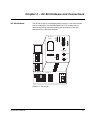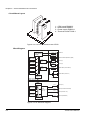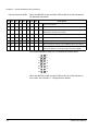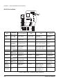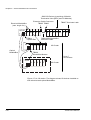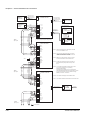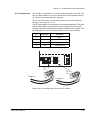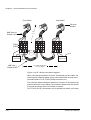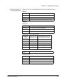
1
ABB Drives
User’s Manual
Advant Controller 80
User’s Manual
Advant Controller 80
3BFE 64116487 R0125 REV A
EFFECTIVE: 21.2.2000
SUPERSEDES: 1.6.1999
© 2000 ABB Industry Oy. All Rights Reserved.
Safety Instructions
General Safety
Instructions
WARNING! All electrical installation and maintenance work on the
drive should be carried out by qualified electricians.
Any installation work must be done with the power off, and power is not
to be reconnected unless the installation work is complete. Dangerous
residual voltages remain in capacitors when the disconnecting device
is opened. Wait 5 minutes after switching off the supply before starting
work. Always ensure that the measured voltage between terminals
UDC+ and UDC- and frame is close to 0 V and that the supply has
been switched off before performing any work on the equipment or
making main circuit connections.
If the main circuit of the inverter unit is live, the motor terminals are also
live even if the motor is not running!
If there are inverters in parallel, open the switch fuses of all parallel
connected inverters before installation or maintenance work on any of
them.
If the auxiliary voltage circuit of the drive is powered from an external
power supply, opening the disconnecting device does not remove all
voltages. Control voltages of 115/230 VAC may be present on the
digital inputs or outputs even though the inverter unit is not powered.
Before starting work, check which circuits remain live after opening of
the disconnecting device by referring to the circuit diagrams for your
particular delivery. Ensure by measuring that the part of the cabinet
you are working on is not live.
Control boards of the drive may be at the main circuit potential.
Dangerous voltages may be present between the control cards and the
frame of the converter unit when the main circuit voltage is on. It is
critical that the use of measuring instruments, such as an oscilloscope,
and their connection to the drive is done with caution and safety always
a priority.
Live parts on the inside of doors are protected against direct contact.
Special safety attention shall be paid when handling shrouds made of
sheet metal.
Do not make any voltage withstand tests on any part of the unit while
the unit is connected. Disconnect motor cables before making any
measurements on motors or motor cables.
Do not open the drive section switch fuses when the inverter is running.
AC 80 User’s Manual
i
Safety Instructions
CAUTION! Fans may continue to rotate for a while after the
disconnection of the electrical supply.
CAUTION! Some parts like heatsinks of power semiconductors inside
of cabinet remain hot for a while after the disconnection of the electrical
supply.
ii
AC 80 User’s Manual
Table of Contents
Safety Instructions
General Safety Instructions . . . . . . . . . . . . . . . . . . . . . . . . . . . . . . . . . . . . . . . . . . . . . . . . . . . . . . i
Chapter 1 – Introduction
Overview . . . . . . . . . . . . . . . . . . . . . . . . . . . . . . . . . . . . . . . . . . . . . . . . . . . . . . . . . . . . . . . . . . 1-1
What This Manual Contains . . . . . . . . . . . . . . . . . . . . . . . . . . . . . . . . . . . . . . . . . . . . . . . . . . . 1-1
AC 80 Connections . . . . . . . . . . . . . . . . . . . . . . . . . . . . . . . . . . . . . . . . . . . . . . . . . . . . . . . . 1-2
Terms, Abbreviations and Definitions . . . . . . . . . . . . . . . . . . . . . . . . . . . . . . . . . . . . . . . . . . . . 1-3
Related Publications . . . . . . . . . . . . . . . . . . . . . . . . . . . . . . . . . . . . . . . . . . . . . . . . . . . . . . . . . 1-4
Chapter 2 – AC 80 Hardware and Connections
AC 80 Hardware . . . . . . . . . . . . . . . . . . . . . . . . . . . . . . . . . . . . . . . . . . . . . . . . . . . . . . . . . . . . 2-1
Circuit Board Layout . . . . . . . . . . . . . . . . . . . . . . . . . . . . . . . . . . . . . . . . . . . . . . . . . . . . . . . 2-2
Block Diagram . . . . . . . . . . . . . . . . . . . . . . . . . . . . . . . . . . . . . . . . . . . . . . . . . . . . . . . . . . . . 2-2
LEDs . . . . . . . . . . . . . . . . . . . . . . . . . . . . . . . . . . . . . . . . . . . . . . . . . . . . . . . . . . . . . . . . . . . 2-3
Bus Indicator LEDs . . . . . . . . . . . . . . . . . . . . . . . . . . . . . . . . . . . . . . . . . . . . . . . . . . . . . . 2-3
Special Purpose LEDs . . . . . . . . . . . . . . . . . . . . . . . . . . . . . . . . . . . . . . . . . . . . . . . . . . . 2-3
General Purpose LEDs . . . . . . . . . . . . . . . . . . . . . . . . . . . . . . . . . . . . . . . . . . . . . . . . . . . 2-4
Station Address Selection . . . . . . . . . . . . . . . . . . . . . . . . . . . . . . . . . . . . . . . . . . . . . . . . . . . 2-5
The INIT Button . . . . . . . . . . . . . . . . . . . . . . . . . . . . . . . . . . . . . . . . . . . . . . . . . . . . . . . . . . . 2-5
AC 80 Connections . . . . . . . . . . . . . . . . . . . . . . . . . . . . . . . . . . . . . . . . . . . . . . . . . . . . . . . . . . 2-6
Power Supply Connection . . . . . . . . . . . . . . . . . . . . . . . . . . . . . . . . . . . . . . . . . . . . . . . . . . . 2-7
Power Supply Terminals . . . . . . . . . . . . . . . . . . . . . . . . . . . . . . . . . . . . . . . . . . . . . . . . . . 2-7
Non-redundant Power Supply Connection . . . . . . . . . . . . . . . . . . . . . . . . . . . . . . . . . . . . 2-8
Redundant Power Supply Connection . . . . . . . . . . . . . . . . . . . . . . . . . . . . . . . . . . . . . . . 2-9
Power-up Procedure . . . . . . . . . . . . . . . . . . . . . . . . . . . . . . . . . . . . . . . . . . . . . . . . . . . . 2-10
ModuleBus Connection . . . . . . . . . . . . . . . . . . . . . . . . . . . . . . . . . . . . . . . . . . . . . . . . . . . . 2-11
Electrical ModuleBus. . . . . . . . . . . . . . . . . . . . . . . . . . . . . . . . . . . . . . . . . . . . . . . . . . . . 2-11
Optical ModuleBus . . . . . . . . . . . . . . . . . . . . . . . . . . . . . . . . . . . . . . . . . . . . . . . . . . . . . 2-11
Size of the I/O Station . . . . . . . . . . . . . . . . . . . . . . . . . . . . . . . . . . . . . . . . . . . . . . . . . . . 2-11
DriveBus Connection . . . . . . . . . . . . . . . . . . . . . . . . . . . . . . . . . . . . . . . . . . . . . . . . . . . . . . 2-13
Panel/Printer Connection (Ch2) . . . . . . . . . . . . . . . . . . . . . . . . . . . . . . . . . . . . . . . . . . . . . 2-14
Wiring Principle . . . . . . . . . . . . . . . . . . . . . . . . . . . . . . . . . . . . . . . . . . . . . . . . . . . . . . . . 2-14
AF 100 Connection . . . . . . . . . . . . . . . . . . . . . . . . . . . . . . . . . . . . . . . . . . . . . . . . . . . . . . . 2-17
Special I/O Connection . . . . . . . . . . . . . . . . . . . . . . . . . . . . . . . . . . . . . . . . . . . . . . . . . . . . 2-19
Fieldbus Adapter Connection . . . . . . . . . . . . . . . . . . . . . . . . . . . . . . . . . . . . . . . . . . . . . . . 2-19
Tool Connection . . . . . . . . . . . . . . . . . . . . . . . . . . . . . . . . . . . . . . . . . . . . . . . . . . . . . . . . . . 2-19
AC 80 User’s Manual
iii
Chapter 3 – AC 80 Software
Overview . . . . . . . . . . . . . . . . . . . . . . . . . . . . . . . . . . . . . . . . . . . . . . . . . . . . . . . . . . . . . . . . . .
AC 80 CPU System Program . . . . . . . . . . . . . . . . . . . . . . . . . . . . . . . . . . . . . . . . . . . . . . . . . .
Boot Program . . . . . . . . . . . . . . . . . . . . . . . . . . . . . . . . . . . . . . . . . . . . . . . . . . . . . . . . . . . .
Base Software. . . . . . . . . . . . . . . . . . . . . . . . . . . . . . . . . . . . . . . . . . . . . . . . . . . . . . . . . . . .
Application Program . . . . . . . . . . . . . . . . . . . . . . . . . . . . . . . . . . . . . . . . . . . . . . . . . . . . . . .
AC 80 NCB System Program . . . . . . . . . . . . . . . . . . . . . . . . . . . . . . . . . . . . . . . . . . . . . . . . . .
AMC Boot Program . . . . . . . . . . . . . . . . . . . . . . . . . . . . . . . . . . . . . . . . . . . . . . . . . . . . . . . .
NCBOS . . . . . . . . . . . . . . . . . . . . . . . . . . . . . . . . . . . . . . . . . . . . . . . . . . . . . . . . . . . . . . . . .
AMC Table . . . . . . . . . . . . . . . . . . . . . . . . . . . . . . . . . . . . . . . . . . . . . . . . . . . . . . . . . . . . . .
AC 80 Software Support on PC . . . . . . . . . . . . . . . . . . . . . . . . . . . . . . . . . . . . . . . . . . . . . . . .
AC 80 CPU Support . . . . . . . . . . . . . . . . . . . . . . . . . . . . . . . . . . . . . . . . . . . . . . . . . . . . . . .
AC 80 Loader . . . . . . . . . . . . . . . . . . . . . . . . . . . . . . . . . . . . . . . . . . . . . . . . . . . . . . . . . .
AdvaBuild . . . . . . . . . . . . . . . . . . . . . . . . . . . . . . . . . . . . . . . . . . . . . . . . . . . . . . . . . . . . .
AC 80 Libraries. . . . . . . . . . . . . . . . . . . . . . . . . . . . . . . . . . . . . . . . . . . . . . . . . . . . . . . . .
AC 80 NCB Support . . . . . . . . . . . . . . . . . . . . . . . . . . . . . . . . . . . . . . . . . . . . . . . . . . . . . . .
NCB Loader . . . . . . . . . . . . . . . . . . . . . . . . . . . . . . . . . . . . . . . . . . . . . . . . . . . . . . . . . . .
DriveDebug. . . . . . . . . . . . . . . . . . . . . . . . . . . . . . . . . . . . . . . . . . . . . . . . . . . . . . . . . . . .
3-1
3-1
3-1
3-1
3-1
3-2
3-2
3-2
3-2
3-3
3-3
3-3
3-3
3-3
3-4
3-4
3-4
Chapter 4 – Programming the AC 80
Overview . . . . . . . . . . . . . . . . . . . . . . . . . . . . . . . . . . . . . . . . . . . . . . . . . . . . . . . . . . . . . . . . . . 4-1
The PM825 Element . . . . . . . . . . . . . . . . . . . . . . . . . . . . . . . . . . . . . . . . . . . . . . . . . . . . . . . . . 4-1
Base Part Terminals . . . . . . . . . . . . . . . . . . . . . . . . . . . . . . . . . . . . . . . . . . . . . . . . . . . . . . . 4-1
AF 100 Part Terminals . . . . . . . . . . . . . . . . . . . . . . . . . . . . . . . . . . . . . . . . . . . . . . . . . . . . . 4-2
Serial IF Part Terminals . . . . . . . . . . . . . . . . . . . . . . . . . . . . . . . . . . . . . . . . . . . . . . . . . . . . 4-2
Control of Drives through Optical ModuleBus. . . . . . . . . . . . . . . . . . . . . . . . . . . . . . . . . . . . . . 4-3
PC Section . . . . . . . . . . . . . . . . . . . . . . . . . . . . . . . . . . . . . . . . . . . . . . . . . . . . . . . . . . . . . . 4-3
DB Section . . . . . . . . . . . . . . . . . . . . . . . . . . . . . . . . . . . . . . . . . . . . . . . . . . . . . . . . . . . . . . 4-3
Configuration of DB Elements for ACS 600 Standard Drive . . . . . . . . . . . . . . . . . . . . . . . . 4-4
DB Elements. . . . . . . . . . . . . . . . . . . . . . . . . . . . . . . . . . . . . . . . . . . . . . . . . . . . . . . . . . . 4-4
Essential Settings for ACS 600 Standard Drive . . . . . . . . . . . . . . . . . . . . . . . . . . . . . . . 4-6
Configuration of DB Elements for ACS 600 MultiDrive . . . . . . . . . . . . . . . . . . . . . . . . . . . . 4-7
DB Elements. . . . . . . . . . . . . . . . . . . . . . . . . . . . . . . . . . . . . . . . . . . . . . . . . . . . . . . . . . . 4-7
Essential Settings for ACS 600 MultiDrive . . . . . . . . . . . . . . . . . . . . . . . . . . . . . . . . . . . 4-9
Activation. . . . . . . . . . . . . . . . . . . . . . . . . . . . . . . . . . . . . . . . . . . . . . . . . . . . . . . . . . . . . . . 4-10
Testing . . . . . . . . . . . . . . . . . . . . . . . . . . . . . . . . . . . . . . . . . . . . . . . . . . . . . . . . . . . . . . . . 4-10
Example: ACS 600 MultiDrive on Optical ModuleBus. . . . . . . . . . . . . . . . . . . . . . . . . . . . . 4-11
Control of Drives through DriveBus . . . . . . . . . . . . . . . . . . . . . . . . . . . . . . . . . . . . . . . . . . . . 4-12
DB Elements . . . . . . . . . . . . . . . . . . . . . . . . . . . . . . . . . . . . . . . . . . . . . . . . . . . . . . . . . . . . 4-12
PC Elements . . . . . . . . . . . . . . . . . . . . . . . . . . . . . . . . . . . . . . . . . . . . . . . . . . . . . . . . . . . . 4-12
Essential Settings . . . . . . . . . . . . . . . . . . . . . . . . . . . . . . . . . . . . . . . . . . . . . . . . . . . . . . . . 4-14
Activation. . . . . . . . . . . . . . . . . . . . . . . . . . . . . . . . . . . . . . . . . . . . . . . . . . . . . . . . . . . . . . . 4-14
Testing . . . . . . . . . . . . . . . . . . . . . . . . . . . . . . . . . . . . . . . . . . . . . . . . . . . . . . . . . . . . . . . . 4-14
Example: ACS 600 MultiDrive on DriveBus . . . . . . . . . . . . . . . . . . . . . . . . . . . . . . . . . . . 4-15
Configuring the Electrical ModuleBus . . . . . . . . . . . . . . . . . . . . . . . . . . . . . . . . . . . . . . . . . . . 4-16
DB Elements for S800 I/O Modules . . . . . . . . . . . . . . . . . . . . . . . . . . . . . . . . . . . . . . . . . . 4-16
S800 Analogue Input Modules . . . . . . . . . . . . . . . . . . . . . . . . . . . . . . . . . . . . . . . . . . . . . . 4-19
S800 Analogue Output Modules . . . . . . . . . . . . . . . . . . . . . . . . . . . . . . . . . . . . . . . . . . . . 4-19
iv
AC 80 User’s Manual
S800 Digital Input Modules . . . . . . . . . . . . . . . . . . . . . . . . . . . . . . . . . . . . . . . . . . . . . . . . .
S800 Digital Output Modules . . . . . . . . . . . . . . . . . . . . . . . . . . . . . . . . . . . . . . . . . . . . . . .
Essential Terminal Settings . . . . . . . . . . . . . . . . . . . . . . . . . . . . . . . . . . . . . . . . . . . . . . . .
Control of the Panel/Printer Link . . . . . . . . . . . . . . . . . . . . . . . . . . . . . . . . . . . . . . . . . . . . . . .
Panel/Printer Link in Panelbus Mode . . . . . . . . . . . . . . . . . . . . . . . . . . . . . . . . . . . . . . . . .
DB Elements . . . . . . . . . . . . . . . . . . . . . . . . . . . . . . . . . . . . . . . . . . . . . . . . . . . . . . . . . .
PC Elements . . . . . . . . . . . . . . . . . . . . . . . . . . . . . . . . . . . . . . . . . . . . . . . . . . . . . . . . . .
Essential Settings . . . . . . . . . . . . . . . . . . . . . . . . . . . . . . . . . . . . . . . . . . . . . . . . . . . . . .
Panel/Printer Link in MultiVendor Mode . . . . . . . . . . . . . . . . . . . . . . . . . . . . . . . . . . . . . . .
PC Elements . . . . . . . . . . . . . . . . . . . . . . . . . . . . . . . . . . . . . . . . . . . . . . . . . . . . . . . . . .
DB Elements . . . . . . . . . . . . . . . . . . . . . . . . . . . . . . . . . . . . . . . . . . . . . . . . . . . . . . . . . .
Essential Settings . . . . . . . . . . . . . . . . . . . . . . . . . . . . . . . . . . . . . . . . . . . . . . . . . . . . . .
Activation . . . . . . . . . . . . . . . . . . . . . . . . . . . . . . . . . . . . . . . . . . . . . . . . . . . . . . . . . . . . . . .
Testing . . . . . . . . . . . . . . . . . . . . . . . . . . . . . . . . . . . . . . . . . . . . . . . . . . . . . . . . . . . . . . . . .
Control of the AF 100 Link . . . . . . . . . . . . . . . . . . . . . . . . . . . . . . . . . . . . . . . . . . . . . . . . . . . .
Addressing . . . . . . . . . . . . . . . . . . . . . . . . . . . . . . . . . . . . . . . . . . . . . . . . . . . . . . . . . . . . . .
Communication between Advant Controllers . . . . . . . . . . . . . . . . . . . . . . . . . . . . . . . . . . .
DB Elements . . . . . . . . . . . . . . . . . . . . . . . . . . . . . . . . . . . . . . . . . . . . . . . . . . . . . . . . . . . .
PC Elements . . . . . . . . . . . . . . . . . . . . . . . . . . . . . . . . . . . . . . . . . . . . . . . . . . . . . . . . . . . .
Essential Settings . . . . . . . . . . . . . . . . . . . . . . . . . . . . . . . . . . . . . . . . . . . . . . . . . . . . . . . .
Activation . . . . . . . . . . . . . . . . . . . . . . . . . . . . . . . . . . . . . . . . . . . . . . . . . . . . . . . . . . . . . . .
Testing . . . . . . . . . . . . . . . . . . . . . . . . . . . . . . . . . . . . . . . . . . . . . . . . . . . . . . . . . . . . . . . . .
Example: AF 100 Communication between AC 80s . . . . . . . . . . . . . . . . . . . . . . . . . . . . . .
Control of the Special I/O Link . . . . . . . . . . . . . . . . . . . . . . . . . . . . . . . . . . . . . . . . . . . . . . . . .
DB Elements . . . . . . . . . . . . . . . . . . . . . . . . . . . . . . . . . . . . . . . . . . . . . . . . . . . . . . . . . . . .
PC Elements . . . . . . . . . . . . . . . . . . . . . . . . . . . . . . . . . . . . . . . . . . . . . . . . . . . . . . . . . . . .
Essential Settings . . . . . . . . . . . . . . . . . . . . . . . . . . . . . . . . . . . . . . . . . . . . . . . . . . . . . . . .
Activation . . . . . . . . . . . . . . . . . . . . . . . . . . . . . . . . . . . . . . . . . . . . . . . . . . . . . . . . . . . . . . .
Testing . . . . . . . . . . . . . . . . . . . . . . . . . . . . . . . . . . . . . . . . . . . . . . . . . . . . . . . . . . . . . . . . .
Example: DSU (Diode Supply Unit) on the Special I/O Link . . . . . . . . . . . . . . . . . . . . . . . .
Control of the Fieldbus Adapter Link . . . . . . . . . . . . . . . . . . . . . . . . . . . . . . . . . . . . . . . . . . . .
4-19
4-19
4-20
4-21
4-21
4-21
4-22
4-23
4-25
4-25
4-25
4-27
4-28
4-28
4-30
4-30
4-30
4-30
4-31
4-32
4-33
4-33
4-34
4-35
4-36
4-36
4-37
4-37
4-38
4-38
4-38
Chapter 5 – Diagnostics
Overview . . . . . . . . . . . . . . . . . . . . . . . . . . . . . . . . . . . . . . . . . . . . . . . . . . . . . . . . . . . . . . . . . .
LEDs . . . . . . . . . . . . . . . . . . . . . . . . . . . . . . . . . . . . . . . . . . . . . . . . . . . . . . . . . . . . . . . . . . . . .
Bus Indicator LEDs . . . . . . . . . . . . . . . . . . . . . . . . . . . . . . . . . . . . . . . . . . . . . . . . . . . . . . . .
PC . . . . . . . . . . . . . . . . . . . . . . . . . . . . . . . . . . . . . . . . . . . . . . . . . . . . . . . . . . . . . . . . . . .
Dbus . . . . . . . . . . . . . . . . . . . . . . . . . . . . . . . . . . . . . . . . . . . . . . . . . . . . . . . . . . . . . . . . .
I/O . . . . . . . . . . . . . . . . . . . . . . . . . . . . . . . . . . . . . . . . . . . . . . . . . . . . . . . . . . . . . . . . . . .
FBA . . . . . . . . . . . . . . . . . . . . . . . . . . . . . . . . . . . . . . . . . . . . . . . . . . . . . . . . . . . . . . . . . .
General Purpose LEDs S0 to S7 . . . . . . . . . . . . . . . . . . . . . . . . . . . . . . . . . . . . . . . . . . . . .
Checking the System Status Using FCB . . . . . . . . . . . . . . . . . . . . . . . . . . . . . . . . . . . . . . . . . .
PC Element Error Terminals and Codes . . . . . . . . . . . . . . . . . . . . . . . . . . . . . . . . . . . . . . . .
Using DriveDebug . . . . . . . . . . . . . . . . . . . . . . . . . . . . . . . . . . . . . . . . . . . . . . . . . . . . . . . . . . .
AC 80 User’s Manual
5-1
5-1
5-1
5-1
5-1
5-1
5-1
5-2
5-4
5-4
5-5
v
vi
AC 80 User’s Manual
Chapter 1 – Introduction
Overview
The Advant® Controller 80 (AC 80) is a high-performance
programmable logic controller specially designed for drives.
Here are a few basic functions of the AC 80:
• Execution of fast drive control application programs
• Communication with drives
• Communication with other controllers
• Communication with S800 I/O, special I/O and fieldbus adapter units
• Modbus-protocol panel/printer port.
The AdvaBuild for Windows program suite (more specifically, the
Function Chart Builder) can be used for programming, configuring and
diagnosing of the AC 80. Configuring and programming the AC 80
looks and feels the same as other Advant controllers. Compatibility to
the APC2 (Application Program Controller; the previous-generation
controller) is preserved when using function blocks from the APC2
library.
PM825, the processor module of the AC 80, is based on an MC68360
microprocessor running at 25 MHz in 16-bit mode. The system and
user application programs are stored in 1024 KB and 512 KB of FLASH
PROM respectively. 1024 kilobytes (512K*16bit) of RAM is available for
the execution of the system and user application programs.
The AC 80 may be used either independently (stand-alone) or as part
of an AF 100 (Advant Fieldbus 100) network. The user interfaces of the
AC 80 are DriveWindow, Modbus-protocol panels and printers, and the
Man-Machine Interface via AF 100.
What This Manual
Contains
Chapter 2 contains a description of the AC 80 hardware and
connections, including terminal designations and bus topology
diagrams.
Chapter 3 is a summary of the software relating to the AC 80. It deals
with the programs residing in the AC 80 as well as supporting PC
software.
Chapter 4 explains how the connections of the AC 80 are set up in the
AC 80 application program. This chapter is mainly intended for persons
responsible for the application program of the AC 80. The reader is
expected to have a knowledge of AdvaBuild/Function Chart Builder
programming.
Chapter 5 gives information on diagnosing the AC 80 using its LEDs
and the supporting PC software.
AC 80 User’s Manual
1-1
AC 80 Connections
Figure 1-1 AC 80 Connections.
AC400 Series
Controller
Advant Fieldbus 100
Service Link (RS 232C)
Tools Link
PC Tools (e.g. DriveDebu
Fieldbus Link
Fieldbus Adapter
(e.g. PROFIBUS)
Panel/Printer Link (Modbus/RS-485)
NMBC
NMBC
Special I/O Link
NAPI
NAPI
Special I/O Devices,
DSU Supply Units
Electrical ModuleBus
DriveBus
S800 I/O Devices
NDBU
NDBU
NDBU
NDBU
Optical ModuleBus
AC 80 User’s Manual
I/O Clusters (S800 I/O Devices)
NAMC
NAMC
NAMC
Motor
Control
Motor
Control
Motor
Control
Inverter
Inverter
Inverter
Inverter
Inverter
Inverter
Supply
Supply
Drives,
Supply Units
Chapter 1 – Introduction
1-2
AC110 Series
Controller
Chapter 1 – Introduction
Terms, Abbreviations
and Definitions
AdvaBuild (for Windows)
A package of programming tools.
Advant Fieldbus 100 (AF 100)
A twisted pair fieldbus that provides communication between Advant
Controllers, I/O stations and higher-level computer systems.
APC2
Application Program Controller; previous-generation drive-specific
control system.
Control Panel
A separate device which can be used for diagnostics and control, e.g.
CDP 80, AOS.
DDCS
Distributed Drives Communication System; a communication protocol
used in fibre optic links in ABB drives.
Drive
A single NAMC-based inverter, or several inverters each containing an
NAMC board, connected to one line-up.
DSU
Diode Supply Unit; one of ACS 600 supply unit types.
FCB
Function Chart Builder; part of AdvaBuild; a PC tool for writing
application programs.
FCI
Fieldbus Communication Interface; contains an interface to the AF 100
fieldbus, a ModuleBus interface, and power regulators. The FCI uses
S800 I/O devices. For further information on FCI units, refer to the
S800 I/O User’s Guide.
Fieldbus Adapter
A device that allows communication with another fieldbus system, e.g.
PROFIBUS DP, InterBus-S.
GOP
Graphic Operator Panel; a type of control panel used especially in Pulp
& Paper applications.
I/O
Input/output.
I/O Cluster
An extension of the ModuleBus optical link of an AC 80. Consists of a
ModuleBus modem with I/O devices.
I/O Device
A complete I/O device consists of one MTU and one I/O module.
I/O Module
The active, electronic, and signal conditioning part of an I/O device.
AC 80 User’s Manual
1-3
Chapter 1 – Introduction
I/O Station
An I/O station consists of an AC 80 (or an FCI), 1 to 7 I/O clusters and
up to 24 I/O devices.
ISU
Inverter Supply Unit; one of ACS 600 supply unit types.
ModuleBus
An incremental, electrical or optical bus for interconnection of I/O
devices.
MTU
Module Termination Unit; a passive unit onto which an I/O module is
mounted. The MTU contains the process I/O terminals and part of
Electrical ModuleBus.
OSP
Outputs Set as Predetermined; a user-configurable action on an output
module when communication is lost to the AC 80.
S800 I/O
Type of a distributed modular I/O unit which communicates with Advant
controllers over an AF100 bus or directly with AC 80.
Special I/O
An interface for special I/O, such as the NBIO-31 I/O unit, the NPCT-01
Pulse Counter Board, or DSU connections.
Tools
PC software (such as DriveWindow and FCB) used for monitoring and
controlling drives, or designing drive application programs.
TSU
Thyristor Supply Unit; one of ACS 600 supply unit types.
Related Publications
AC 80 PC Elements Reference Manual (3BFE 64021737, English)
Advant Fieldbus 100 User’s Guide (3BSE 000 506, English)
Firmware Manual for ACS 600 System Application Program
(3AFY 63700177, English)
Firmware Manual for ACS 600 Standard Application Program
(3AFY 61201441, English)
Function Blocks for APC2 (3AFY 61281240, English)
S800 I/O User’s Guide (3BSE 008 878, English)
Use of PROFIBUS-DP Protocol in Advant Controller 80
(3BFE 64248260, English).
1-4
AC 80 User’s Manual
Chapter 2 – AC 80 Hardware and Connections
AC 80 Hardware
The AC 80 is built in a ventilated plastic housing. It can be mounted
onto a horizontal or vertical DIN 50022 rail. The module can be
removed by pulling the locking spring (at the bottom of the unit)
downwards e.g. with a screwdriver.
Tx Rx
F
PC
B
Dbus
T1
I/O
S7
FBA
S6
S5
S4
R
P
T2
S3
S2
S1
S0
INIT
Tx
Rx
SERVICE
Ch2
STN. ADDR.
5 6
4
3
7 x10
2
8
1 0 9
5 6
4
7 x1
3
2
8
1 0 9
Ch1
L+ L+ SA
L– L– SB
1 AF100 2
Figure 2-1 The AC 80.
AC 80 User’s Manual
2-1
Chapter 2 – AC 80 Hardware and Connections
Circuit Board Layout
3
2
1
1–
2–
3–
4–
68360
CPU board PM820-2
NCB board PM825-1
Power supply PM820-1
Terminal board TC820-1
4
Figure 2-2 The circuit boards of the AC 80.
Block Diagram
MAIN
PROCESSOR
(68360)
RS-232
RS-485
CH1
SERVICE
CH2
PANEL/PRINTER (MODBUS) (MMI)
RAM
(512k x 16 bit)
RS-232
COMM.
CONTROLLER
(BAP)
FLASH (SYS)
(256k x 32 bit)
FLASH (USER)
(256k x 16 bit)
COMM.
CONTROLLER
(DDCC+)
WATCHDOG
REAL TIME
CLK/CALEND.
AF100
MODEM
AF100 (1)
AF100
MODEM
AF100 (2)
RS-485
X
10
MODULEBUS (ELECTRICAL)
MODULEBUS (OPTICAL)
BUS
BUFFERS
TB810 or TB811
PM820-2 CPU board
PM820-1 Terminal b.
PM825-1 NCB
DP RAM
(16k x 16 bit)
CH3
RAM
(128k x 24 bit)
CH2
COMM.
CONTROLLER
(ICMC 2A)
BOOT PROM
(32k x 8 bit)
FLASH
(512k x 8 bit)
CH1
CH0
DDCS (PC)
DDCS (FIELDBUS ADAPTER)
DDCS (SPECIAL I/O)
DDCSe (DRIVEBUS)
I/O PROCESSOR
(DSP 56002)
Figure 2-3 AC 80 block diagram.
2-2
AC 80 User’s Manual
Chapter 2 – AC 80 Hardware and Connections
LEDs
The LEDs on the AC 80 can be divided into three groups, i.e. bus
indicator LEDs, general purpose LEDs, and special purpose LEDs.
(Further information on the LEDs is given in Chapter 5 – Diagnostics).
Tx Rx
PC
F
R
Dbus
B
P
I/O
T1
T2
FBA
S7
S3
S6
S2
S5
S1
S4
S0
Bus Indicator
LEDs
Special
Purpose LEDs
General
Purpose LEDs
Figure 2-4 LEDs of the AC 80.
Bus Indicator LEDs
These LEDs show the status of the fibre optic channels. The LEDs are
laid out in the same order as the optic terminals on the AC 80.
Note that the Rx LEDs light when data is received from the fibre optic
link. The Tx LEDs are controlled by the AC 80 itself.
Special Purpose LEDs
F – Fault (red): This LED switches automatically on after the power-up
of the AC 80. The system application program also lights this LED if the
self test fails. In case of a serious hardware or program error, this LED
lights. Simultaneously, the general purpose LEDs indicate an error
code. Note: The error codes are given in Chapter 5 – Diagnostics.
R – Run (green): This LED is lit when the system application starts to
run. It turns off upon serious hardware or program errors.
P – Power (green): This LED indicates that the power supply to the
AC 80 is good. The P LED is independent of system program status.
B – Battery (green): This LED indicates that the voltage level of the
battery is sufficient for backing up the internal real time clock and
buffered read/write memory. If no battery is inserted, or it is low, the B
LED is turned off.
T1, T2 (yellow): These LEDs indicate data being received on the
AF 100 channels 1 and 2 respectively. If the AC 80 is not connected to
AF 100, these LEDs are off. If the AC 80 is connected to the AF 100
with only one cable, one of the LEDs should be on, the other LED off.
AC 80 User’s Manual
2-3
Chapter 2 – AC 80 Hardware and Connections
General Purpose LEDs
S7
S6
S5
S4
S3
When the S7 LED is on, and the F LED is off, S0 to S6 indicate the
AC 80 status as follows:
S2
S1
S0
on
on
on
on
on
on
on
on
on
on
on
on
on
on
on
on
on
on
on
on
P-
CPU in initial phase
on
P1
CPU in operational mode
on
P3
CPU has stopped after initialisation. START MODE attribute at
DB element has been set to STOP
P4
CPU is not running an application program
P5
CPU is loading an application program from the internal PROM
P6
Programming tool is connected (CPU is in on-line mode)
--
Boot-up program erasing system PROM (prepare for loading)
PL
Boot-up program waiting for system program download (after
erasure or detection of corrupt program in system PROM)
on
on
on
AC 80 Status
on
The normal operation state (P1) is indicated as shown below:
F
R
B
P
T1
T2
S7
S3
S6
S2
S5
S1
S4
S0
When the S7 LED is off, and the F LED is on, S0 to S6 indicate an
error code. See Chapter 5 – Diagnostics for details.
2-4
AC 80 User’s Manual
Chapter 2 – AC 80 Hardware and Connections
Station Address
Selection
The AC 80 is equipped with two address selection switches. They are
used for defining an exclusive station address for the AC 80 on the
AF 100 bus. The address must be in the range of 1 to 79; setting the
address outside this range renders the AC 80 unaccessible via AF 100.
Note: The address selected with the hardware switches must match
the station number setting in the application program (STNNO in
PM825 element, AF 100 part).
The INIT Button
AC 80 User’s Manual
Pressing the INIT button performs a “cold start”, i.e. the AC 80
performs self tests, checks the user memory for a valid application and
activates it, runs a complete initialisation and I/O module configuration.
2-5
Chapter 2 – AC 80 Hardware and Connections
AC 80 Connections
7
1
5
4
3
2
1 0
5
4
3
2
1 0
2
Tx
Rx
Ch2
6
9
7
8
6
9
7
8
SERVICE
3
4
5
Ch1
L+ L+ SA
1
AF100
2
+
–
SH
SH
+
–
SH
SH
Tx
6
Rx
L– L– SB
Name
Terminal
(see above)
For connection of
Cable
Data
Remark
Power
Supply
L+ L+ SA
L– L– SB
Power Supply
0.2 to 2.5 mm2
+24 V d.c.
(19.2 to 30 V)
Redundancy
available
AF 100
AF100 1
AF100 2
AF 100 (Advant
Fieldbus 100)
Screened twisted
pair
Max. length 750 m
Max. no. of nodes 32
Redundancy
available
Service
Ch1
(Terminal
Board X4)
PC (Configuration
and Maintenance)
RS-232
RS-232 signal levels
Max. comm. 20 kbit/s
D-sub
9-pole
Panel/Printer
Ch2
(Terminal
Board X5)
CDP 80 Ctrl. Panel
Alarm printer
GOP Panel
RS-485
Protocol: Modbus
RS-485 signal levels
Max. comm. TBD
D-sub
15-pole
Battery
1
Battery
–
Lithium 3.6 V 900 mAh
14.5 × 25 mm
Tool*
2
PC tools
(DriveDebug)
Fibre optic
Protocol: DDCS
10 MBd optical
components
ABB drives
Branching units
Fibre optic
Protocol: DDCS,
DDCSe
10 MBd optical
components
NBIO-21, NBIO-31,
NPCT-01, DSU
Fibre optic
Protocol: DDCS
5 MBd optical
components
Fieldbus Adapters,
e.g. NPBA-80
Fibre optic
Protocol: DDCS
5 MBd optical
components
Requires
TB810/811
Optical Port
(NCB CH3)
DriveBus*
3
(NCB CH0)
Special I/O*
4
(NCB CH1)
Fieldbus
Adapter*
5
(NCB CH2)
Optical
ModuleBus
(optional)*
6
TB820 Modems
ABB drives
Fibre optic
Protocol: DDCS
Max. 12 I/O units in
max. 7 clusters
Electrical
ModuleBus
7
S800 I/O units
C/4 Plug-in
Max. 12 I/O units
24 V supply 1.0 A
5 V supply 2 A
*Colour codes: Grey: Transmitter, Blue: Receiver.
2-6
AC 80 User’s Manual
Chapter 2 – AC 80 Hardware and Connections
Power Supply
Connection
The AC 80 is powered by a single or redundant 24 V d.c. (19.2 to 30 V)
supply. The table below gives the current consumption at three different
voltages (without I/O modules).
Current [mA]
Voltage [V d.c.]
Power Supply Terminals
Typical
Maximum
19.2
310
520
24
250
415
30
200
330
The power supply terminals accept wire sizes from 0.2 to 2.5 mm2
(24 to 14 AWG). The terminal designations are as follows:
X1B
Designation
Description
1
L+
+24 V (in)
2
L+
+24 V (out)
3
SA
Redundant power supply monitor input
X1A
Designation
Description
1
L–
0 V (in)
2
L–
+0 V (out)
3
SA
Redundant power supply monitor input
Note: It is recommended that the AC 80 and the I/O devices be
powered from separate supplies.
AC 80 User’s Manual
2-7
Chapter 2 – AC 80 Hardware and Connections
Non-redundant Power
Supply Connection
Forwarded Power
Electrical
ModuleBus
X9
PM 820-1
X1B
X1A
SB
3
3
SA
2
2
L–
DC
L+
DC
1
1
DIN Rail
+24 V
0V
1
L+ L+ SA
AF100
2
+
–
SH
SH
X1B
X1A
+
–
SH
SH
Tx
Rx
L– L– SB
1
2
3
+24 V
X1B
Forwarded Power
From
+24 V
Power Supply
1
X1A
2
3
0V
0V
Figure 2-5 Non-redundant power supply connection.
2-8
AC 80 User’s Manual
Chapter 2 – AC 80 Hardware and Connections
Redundant Power Supply
Connection
Forwarded Power
Electrical
ModuleBus
X9
PM 820-1
X1B X1A
SB 3
3
SA
2
2
L–
DC
L+
DC
1
1
DIN Rail
Supervision
POWER VOTER UNIT
+24 V /A
+24 V /B
0V
1
L+ L+ SA
AF100
2
+
–
SH
SH
X1B
X1A
+
–
SH
SH
Tx
Rx
L– L– SB
Power Supply
B Monitor
Power Supply
A Monitor
1
2
3
+24 V
X1B
Forwarded Power
From
+24 V
Power Supply
1
X1A
2
3
0V
0V
Figure 2-6 Redundant power supply connection.
AC 80 User’s Manual
2-9
Chapter 2 – AC 80 Hardware and Connections
Power-up Procedure
1. Measure that the voltages are correct on the power switch unit.
2. Switch on the circuit breakers on the power switch.
3. The AC 80 indicates the power-on status with the following LEDs:
2-10
Function
LED
Colour
LED
Designation
Operating OK
Green
R
Power OK
Green
P
Battery OK
Green
B
AF 100 Active
Yellow
(flashing)
T1 and T2
States P1 to P6
Yellow
see page 2-4
Fault/Alarm, I/O Modules/PM820-2
Red
F
AC 80 User’s Manual
Chapter 2 – AC 80 Hardware and Connections
ModuleBus Connection
ModuleBus is used for connecting I/O devices (or ABB drives) to the
AC 80. It is divided into electrical and optical busses which are logically
the same bus.
Electrical ModuleBus
The electrical ModuleBus link is made up of I/O devices installed side
by side on the same mounting rail as the AC 80 itself. Extension cables
may also be used as shown below e.g. in order to install I/O devices of
different types onto different mounting rails. The bus is terminated at
the end with a TB807 terminator latch. The maximum length of the bus
is 2 metres including the AC 80, all I/O devices and extension cables.
Each I/O device consists of a module termination unit (MTU) and an
I/O module installed on it. For more information on the different I/O
devices available, refer to the S800 I/O User’s Guide.
Optical ModuleBus
The optical ModuleBus link is constructed as a ring on the optional
TB810/811 Optical Port, plugged onto the AC 80. The maximum
communication speeds for the TB810 and TB811 are 10 and 5 Mbit/s
respectively.
Each I/O cluster is built around a TB820 ModuleBus Optical Modem,
and forms an individual electrical ModuleBus. Each cluster is given a
cluster address using the selector on the TB820. Instructions for this as
well as other detailed information on the TB820 is available from the
S800 I/O User’s Guide.
Size of the I/O Station
The I/O station may contain 24 I/O devices at most, i.e. 12 devices on
the electrical and 12 on the optical ModuleBus. One I/O station can
handle up to 384 digital I/O signals or 192 analogue I/O signals. The
optical ModuleBus link may contain up to 7 I/O clusters.
The modules are addressed according to their physical order on the
bus.
AC 80 User’s Manual
2-11
Chapter 2 – AC 80 Hardware and Connections
S800 I/O Devices (consisting of Module
Termination Units [MTU] and I/O Modules)
Extension Cable Connector
TB805 TB806
Electrical ModuleBus
(max. length 2 m)
TB807 Terminator Latch
AC 80
1
3 4
2
5
TB81x
Optical Port
X4, X5
1
Optical
ModuleBus
2
6
7
8
9 10 11 12
TK801V00x ModuleBus
Extension Cable
3 4
5
I/O Cluster
TB820
ModuleBus Modem
Up to 7
I/O Clusters
X4, X5
1
2
3 4
5
I/O Cluster
Figure 2-7 An I/O station. The diagram shows I/O devices installed on
both electrical and optical ModuleBus.
2-12
AC 80 User’s Manual
Chapter 2 – AC 80 Hardware and Connections
DriveBus Connection
The optical DriveBus link (Channel 0 on the NCB board) can be used
for controlling 12 NAMC-based drives, inverter units or supply units.
The connection of multiple drives requires the use of a branching unit
(NDBU), which enables the construction of a logical bus with physical
star topology. Branching units can be chained together.
AC 80
DRIVEBUS
MSTR
Branching
Units
CH0
NDBU
CH1
CH2
MSTR
CH1
CH3
CH2
CH0
CH0
CH0
Drive
CH3
CH0
CH0
Up to 12 Drives
(Up to 8 per
branching unit)
•••
NDBU
CH0
Drive
Drive
•••
Drive
Drive
Drive
•••
Figure 2-8 DriveBus topology.
DriveBus uses a communication speed of 4 Mbit/s (8 Mbit/s
provisional), with a message cycle time of 50 µs (asynchronous). The
specified transfer capability is 20 messages (10 data set pairs) per
millisecond, the maximum being 32 messages/ms.
The DriveBus link can employ both plastic and HCS fibre optic cables.
The use of HCS cables enables higher speed and longer distances; the
maximum length of the bus is 15 m for plastic cable, 200 m for HCS
cable. The communication speed and light intensity are set with
jumpers on the NDBU board.
AC 80 User’s Manual
2-13
Chapter 2 – AC 80 Hardware and Connections
Panel/Printer
Connection (Ch2)
The panel/printer connector, labelled Ch2, is a Modbus-protocol
RS-485 interface for up to 8 devices. The panel/printer link can be
operated in two modes (only one of which can be active at a time):
Panelbus mode: for connection of Slave devices such as
• CDP 80 Control Panel. If it is the only device on the link, the
CDP 80 can be directly connected to the panel/printer
connector using an NCPC-30 cable as shown below
AC 80
Ch2
(X5)
NCPC-30
X1
CDP 80
• Centronics-interface alarm printer (see the wiring principle
diagrams below for additional equipment required)
• The Graphical Operator Panel (GOP). Note: Although the GOP
can be operated in Panelbus mode, MultiVendor mode is
recommended.
MultiVendor mode: for connection of
• Graphical Operator Panel (GOP) (see the wiring principle
diagrams below for additional equipment required)
• external Modbus-protocol Slave or Master devices.
MultiVendor mode requires the installation of the optional Embedded
Modbus elements.
Wiring Principle
2-14
The wiring principle of the panel/printer link is shown on the next two
pages.
AC 80 User’s Manual
Chapter 2 – AC 80 Hardware and Connections
N C P C -3 0 C o n tro l
P a n e l C a b le , A C 8 0
A C 8 0
C h 2
A P P L IC A T IO N
C O N T R O L L E R
(L e n g th 3 m )
N M B C -0 1 M O D B U S
T E R M IN A T IO N U N IT
X 1
N C P C -3 0 C o n tro l
P a n e l C a b le , A C 8 0
X 4
P O W E R S U P P L Y
2 4 ...2 8 V D C
(M a x 1 0 A )
2 4 V
+
0 V
-
X 3
1
2 4 V
2
0 V
IN
3
2 4 V
O U T
0 V
O U T
4
( 2 P a ir s )
5
6
D G N D
7
S H IE L D
9
C O N T R O L P A N E L
D o o r P a n e l M o u n tin g
( O p tio n a l)
C o n tro l P a n e l
C a b le ( B la c k ) ,
3 A F E 6 4 0 4 4 7 6 1
D A T A
A (+ )
D A T A
B (-)
X 2
C D P 8 0
C O N T R O L P A N E L
X 1
(L e n g th m a x 1 0 m )
M a le - to - M a le
E x te n s io n
C o n n e c to r
S H IE L D
B (-)
X 3
X 1
D A T A
D A T A
D G N D
2 4 V
0 V
J A M A K
4 x (2 + 1 )x 0 .5
A (+ )
1 0
C D P 8 0
IN
S H IE L D
8
X 1
(L e n g th 3 m )
N D P I-2 1
C O N T R O L P A N E L
IN T E R F A C E
G O P
G R A P H IC A L
O P E R A T IN G P A N E L
X 1
1
S H IE L D
2
R S 4 8 5 A +
3
T E R M IN
4
S H IE L D
6
R S 4 8 5 B -
7
( 2 P a ir s )
N o te 2 : T h e b u s m u s t b e te r m in a te d a t b o th e n d s . A C 8 0
c o n ta in s fix e d te r m in a tio n . T e r m in a tio n o n th e fir s t
N M B C - 0 1 u n it m u s t b e s w itc h e d O F F .
2 4 V
8
0 V
1
S H IE L D
2
R S 4 8 5 A +
3
T E R M IN
N o te 4
4
N o te 3 : N M B C - 0 1 c a n a ls o b e th e la s t ´ d e v ic e ´ in th e b u s .
In th a t c a s e te r m in a tio n m u s t b e s w itc h e d O N .
R S 4 8 5 R E F
5
N o te 4 : If G O P is th e la s t d e v ic e in th e b u s , te r m in a tio n is
im p le m e n te d w ith a ju m p e r b e tw e e n th e p in s 2 & 3
o f X 2 .
S H IE L D
6
R S 4 8 5 B -
7
( 2 P a ir s )
N o te 1 : C D P 8 0 C o n tr o l P a n e l c a n o p tio n a lly b e c o n n e c te d
to X 4 o r X 2 o n N M B C - 0 1 u n it.
R S 4 8 5 R E F
5
2 4 V
8
0 V
N o te 5 : In b u s c a b le tw o p a r a lle l c o n n e c te d p a ir s a r e u s e d
fo r 2 4 V D C . ( R e c o m m e n d e d p r a c tis e .)
S e e p a g e 2 /2 fo r 3 - p a ir w ir in g .
B (-)
D A T A
D A T A
D G N D
2 4 V
0 V
J A M A K
4 x (2 + 1 )x 0 .5
A (+ )
X 2
A L A R M
P R IN T E R IN T E R F A C E
X 1
2
0 V
3
+ 2 4 V
0 V
4
5
S H IE L D
7
9
1 0
D A T A
A (+ )
D A T A
B (-)
X 3
2
0 V
3
+ 2 4 V
to ta l le n g th o f th e M o d b u s is 3 0 0 m .
N o te 7 : T h e m a x im u m
d is ta n c e b e tw e e n C D P 8 0 a n d A C 8 0 is 3 0 m .
C e n tr o n ic s C a b le
(L e n g th m a x 3 m )
A L A R M
P R IN T E R
2 3 0 V A C
( O K I M ic r o lin e 2 8 0 )
S H IE L D
7
8
9
1 0
B
N o te 6 : T h e m a x im u m
D G N D
6
A
4 V w ir in g b e tw e e n
n d p o w e r s u p p ly is 5 o h m .
r e s is ta n c e o f s in g le
.
S H IE L D
5
D A T A
f 2
l a
o p
m
0 V
4
D A T A
c e o
a n e
e lo
/1 0 0
+ 2 4 V
1
D G N D
r e s is ta n
e r a tin g P
n e ls .) T h
8 .1 o h m
S H IE L D
X 2
2 4 V
o p
p
p a
a x
S H IE L D
8
0 V
lo
l O
o
m
D G N D
6
J A M A K
4 x (2 + 1 )x 0 .5
m a x im u m
P G r a p h ic a
o h m fo r tw
A K p a ir is
+ 2 4 V
1
( 2 P a ir s )
T h e
G O
(2 .5
J A M
N A P I-0 1
D A T A
A (+ )
D A T A
B (-)
S H IE L D
T o n e x t d e v ic e
AC 80 User’s Manual
2-15
Chapter 2 – AC 80 Hardware and Connections
N C P C -3 0 C o n tro l
P a n e l C a b le , A C 8 0
A C 8 0
C h 2
A P P L IC A T IO N
C O N T R O L L E R
N M B C -0 1 M O D B U S
T E R M IN A T IO N U N IT
X 1
(L e n g th 3 m )
N C P C -3 0 C o n tro l
P a n e l C a b le , A C 8 0
X 4
P O W E R S U P P L Y
2 4 ...2 8 V D C
(M a x 1 0 A )
2 4 V
+
0 V
-
X 3
1
2 4 V
2
0 V
IN
3
2 4 V
O U T
0 V
O U T
4
( 3 P a ir s )
5
D G N D
7
S H IE L D
9
A (+ )
D A T A
B (-)
X 2
M a le - to - M a le
E x te n s io n
C o n n e c to r
S H IE L D
1
R S 4 8 5 A +
3
T E R M IN
R S 4 8 5 B -
B (-)
7
2 4 V
8
N o te 2 : T h e b u s m u s t b e te r m in a te d a t b o th e n d s . A C 8 0
c o n ta in s fix e d te r m in a tio n . T e r m in a tio n o n th e fir s t
N M B C - 0 1 u n it m u s t b e s w itc h e d O F F .
0 V
S H IE L D
2
R S 4 8 5 A +
3
T E R M IN
(*)
N o te 3 : N M B C - 0 1 c a n a ls o b e th e la s t ´ d e v ic e ´ in th e b u s .
In th a t c a s e te r m in a tio n m u s t b e s w itc h e d O N .
R S 4 8 5 R E F
5
N o te 4 : If G O P is th e la s t d e v ic e in th e b u s , te r m in a tio n is
im p le m e n te d w ith a ju m p e r b e tw e e n th e p in s 2 & 3
o f X 2 .
S H IE L D
6
R S 4 8 5 B -
7
( 3 P a ir s )
N o te 1 : C D P 8 0 C o n tr o l P a n e l c a n o p tio n a lly b e c o n n e c te d
to X 4 o r X 2 o n N M B C - 0 1 u n it.
R S 4 8 5 R E F
S H IE L D
4
2 4 V
8
0 V
N o te 5 : In b u s c a b le th r e e p a r a lle l c o n n e c te d p a ir s a r e u s e d
fo r 2 4 V D C . S e e p a g e 1 /2 fo r 2 - p a ir w ir in g .
( R e c o m m e n d e d p r a c tis e .)
D A T A
B (-)
A L A R M
P R IN T E R IN T E R F A C E
X 1
2
0 V
3
+ 2 4 V
0 V
4
5
S H IE L D
7
(*)
1 0
D A T A
A (+ )
D A T A
B (-)
X 3
2
0 V
3
+ 2 4 V
f 2
l a
o p
m
4 V w ir in g b e tw e e n
n d p o w e r s u p p ly is 5 o h m .
r e s is ta n c e o f s in g le
.
N o te 6 : T h e m a x im u m
to ta l le n g th o f th e M o d b u s is 3 0 0 m .
N o te 7 : T h e m a x im u m
d is ta n c e b e tw e e n C D P 8 0 a n d A C 8 0 is 3 0 m .
C e n tr o n ic s C a b le
(L e n g th m a x 3 m )
A L A R M
P R IN T E R
2 3 0 V A C
( O K I M ic r o lin e 2 8 0 )
0 V
4
S H IE L D
5
D G N D
6
S H IE L D
7
8
9
1 0
B
c e o
a n e
e lo
/1 0 0
+ 2 4 V
1
A
r e s is ta n
e r a tin g P
n e ls .) T h
8 .1 o h m
S H IE L D
X 2
D A T A
o p
p
p a
a x
S H IE L D
8
9
(*)
lo
l O
o
m
D G N D
6
( 3 P a ir s )
m a x im u m
P G r a p h ic a
o h m fo r tw
A K p a ir is
+ 2 4 V
1
D A T A
T h e
G O
(2 .5
J A M
N A P I-0 1
D A T A
A (+ )
X 2
2 4 V
C O N T R O L P A N E L
IN T E R F A C E
S H IE L D
2
1
0 V
N D P I-2 1
X 1
6
2 4 V
X 1
G R A P H IC A L
O P E R A T IN G P A N E L
( 3 P a ir s )
0 V
X 1
(L e n g th m a x 1 0 m )
G O P
5
J A M A K
4 x (2 + 1 )x 0 .5
C O N T R O L P A N E L
O p tio n a l ju m p e r fo r d a ta p a ir s h ie ld g r o u n d in g .
4
J A M A K
4 x (2 + 1 )x 0 .5
C D P 8 0
X 3
(*)
(*)
N o te 4
C o n tro l P a n e l
C a b le ( B la c k ) ,
3 A F E 6 4 0 4 4 7 6 1
D A T A
D A T A
D A T A
2 4 V
0 V
J A M A K
4 x (2 + 1 )x 0 .5
A (+ )
1 0
C O N T R O L P A N E L
D o o r P a n e l M o u n tin g
( O p tio n a l)
S H IE L D
8
C D P 8 0
IN
6
(*)
X 1
(L e n g th 3 m )
D A T A
A (+ )
D A T A
B (-)
S H IE L D
T o n e x t d e v ic e
2-16
AC 80 User’s Manual
Chapter 2 – AC 80 Hardware and Connections
AF 100 Connection
The AC 80 is connected to the AC 400 series controller via an AF 100
bus. It is also possible to connect several AC 80 units together with an
AF 100 bus (a bus administrator required).
For AF 100 connection, the AC 80 must have an exclusive address
number in the range of 1 to 79.
The AF 100 fieldbus is connected to the terminals labelled AF100 (see
below). Redundancy is gained when both channels are connected.
However, the same cable should not be connected to both 1 and 2. The
pin designations for the AF100 terminals (1 and 2) are as follows:
Pin
Designation
Description
1
+
Signal +
2
–
Signal –
3
SH
Shield (Screen)
4
SH
Shield (Screen)
1
AF100
+
–
SH
SH
Ch 1
X2
4
3
2
2
+
–
SH
SH
1
Ch 2
X3
X2
Fieldbus 1
4
3
2
1
X3
Fieldbus 2
Figure 2-9 Connecting the AC 80 to the AF 100 bus.
AC 80 User’s Manual
2-17
Chapter 2 – AC 80 Hardware and Connections
First Station
Last Station
Terminal
Header
min.
2m
IBM Type 6A,
Belden 1215
TC505/
TC506
min.
0.1 m
BLUE
S1 S2 GND
TC501V150
IBM Type 1,
Belden 9182
S1 S2 GND
TC501V150
BLUE
max. cable length 750 m
max. 32 stations
Figure 2-10 AF 100 bus connection diagram.
When connecting the station to the AF 100 twisted pair bus cable, the
incoming and outgoing cables can be connected either directly to the
terminal header or to a TC505/TC506 connection unit.
The minimum distance between stations is 4 metres. If the stations are
located inside the same cabinet, the minimum distance can be shorter
if the total bus length does not exceed 10 metres.
The TC501V150 is a termination unit for twisted pair cable (150 ohms).
2-18
AC 80 User’s Manual
Chapter 2 – AC 80 Hardware and Connections
Special I/O Connection
This DDCS-protocol fibre optic link (Channel 1 on the NCB board) can
be used for connecting up to eight I/O devices to the AC 80. The
devices are addressed 1 to 8, and connected in a ring.
The transmission speed of the Special I/O connection is 4 Mbit/s.
The Special I/O connection can be used with the following devices:
• NBIO-21 (Basic I/O Unit 2), an I/O module with 2 analogue
inputs, 2 analogue outputs, 3 digital inputs and 2 digital outputs.
(One digital input and one digital output are dedicated for the
emergency stop function.)
• NBIO-31 (Basic I/O Unit 3), an I/O module with 4 digital inputs
and 3 digital outputs. (One input and one output are dedicated
for the emergency stop function.)
• NPCT-01 (Pulse Counter and Timer Unit), an I/O module with
two incremental encoder inputs, 4 digital inputs and 4 digital
outputs.
• NDSC-01, the control board of a Diode Supply Unit (DSU).
Fieldbus Adapter
Connection
Tool Connection
This DDCS-protocol, 4 Mbit/s fibre optic link (Channel 2 on the NCB
board) can be used for connecting the AC 80 to a fieldbus such as
PROFIBUS-DP. A fieldbus adapter module acts as an interface
between the fibre optic link and the serial bus.
This DDCS-protocol fibre optic link (Channel 3 on the NCB board) can
be used for connecting the AC 80 to a PC with e.g. DriveDebug.
The PC must be equipped with a PCMCIA/DDCS (laptop) or an
ISA/DDCS (desktop) interface.
The transmission speed used is 1 Mbit/s.
AC 80 User’s Manual
2-19
Chapter 2 – AC 80 Hardware and Connections
2-20
AC 80 User’s Manual
Chapter 3 – AC 80 Software
Overview
The AC 80-related software can be divided into two parts:
• AC 80 software
– AC 80 CPU program
– AC 80 NCB program
• AC 80 software support on the PC.
AC 80 CPU
System Program
The CPU system program consists of the boot program, base software,
and the application program. These are executed in the AC 80 CPU.
Boot Program
The boot program resides permanently in the AC 80 CPU. It receives
the base SW upon downloading.
Base Software
The base software consists of the following parts:
• Real-time operative system based on VRTX32
• HLSC for communication over the Service port (Ch1)
• Communication for drivers for AF100, ModuleBus and the Panel/
Printer link
• Target code for PC element libraries, divided into:
– libraries common to both AC 70 and AC 80
– Drives-specific libraries
– PC element options.
The base software is executed in non-volatile system FPROM. It can
be updated by downloading a new revision.
Application Program
The application program consists of the following parts:
• PC part
• DB part
• Parameter data (PARDATs).
The PC part is headed by 1 PCPGM element, and may have up to 31
tasks (CONTRM, MASTER).
The DB part may include the following DB elements:
– PM825 (AC 80 configuration)
– S800 DB elements (for S800 I/O)
– DATs
– DSP
– NCB elements (DRB00, IO00, DCB00)
– Embedded Modbus options (MVB, MVI)
– Events options (EVS, EVENT).
AC 80 User’s Manual
3-1
Chapter 3 – AC 80 Software
PARDAT handling on the AC 80 differs from that of the AC 70 or APC2.
The actual PARDAT values are stored in a separate segment in nonvolatile FLASH PROM.
The application program is prepared by using the FCB (Function Chart
Builder) tool. The target code is generated by selecting File –
Generate Target Code…. When connected, FCB downloads the
application program with the command Target – Load Application.
The application program is stored in the AC 80 RAM, which is also
where it is executed.
The Target – Save in PROM command creates a back-up of the
application program to User FLASH PROM. On power-down, reset, or
restart, the application program is restored to the RAM and initialised.
Depending on the value of PM825 element parameter STARTMOD, the
application program will either start automatically or remain blocked
until manually deblocked.
AC 80 NCB
System Program
AMC Boot Program
NCBOS
The NCB system program consists of the AMC boot program, NCBOS,
and the AMC table of the AC 80.
The AMC boot program resides in a PROM on a socket. It receives the
NCB software upon downloading and stores it in non-volatile FPROM.
The NCBOS consists of
• AMCOS operative system, including routing
• Communication support for DriveBus, fieldbus adapters and Special
I/O.
The NCBOS automatically adapts to communication configured in the
application program in the CPU.
Upon downloading, the NCBOS is stored in non-volatile FPROM and
started automatically. The NCBOS can be updated by downloading a
new revision; this overwrites the previous NCBOS revision.
On power-down, reset, or restart, the NCBOS in FLASH PROM is
copied to RAM and initialised.
AMC Table
3-2
The AMC table of the NCB contains variables and parameters which
can be accessed by the DriveWindow and DriveDebug tools.
Parameter values are saved to non-volatile FPROM and restored upon
NCB reinitialisation.
AC 80 User’s Manual
Chapter 3 – AC 80 Software
AC 80 Software
Support on PC
The AC 80 software support on the PC can be divided into CPU
support and NCB support.
Follow the installation instructions included with each software
package.
AC 80 CPU Support
CPU support requires an RS-232 serial cable between a COM port of
the PC and the Service port of the AC 80.
AC 80 CPU support includes:
• AC 80 Loader
• AdvaBuild for Windows (not included with AC 80 deliveries; must be
ordered and installed separately)
• AC 80 libraries
– Contain the PC and database (DB) elements.
AC 80 Loader
AdvaBuild
The AC 80 loader downloads the PROM_080.IMG file. This file
contains the current base software.
The AdvaBuild for Windows software package contains the Application
Builder (APB), Function Chart Builder (FCB), and Bus Configuration
Builder (BCB) tools. Several versions (but not revisions) of each tool
can be installed on the same PC.
The Application Builder is used for
– creating and modifying projects, or nodes for the AC 80
– invoking the Type Circuit Editor
– invoking the FCB and the BCB
– defining the location of the AC 80 on the AF 100 bus
– selection of AC 80 library version
– selection of required options.
The Function Chart Builder is used for
– creating and modifying application programs
– downloading and saving the application program
– displaying and forcing application program variables (in on-line mode)
– debugging and changing the application program (in on-line mode).
The application program exists on the FCB tool as target code and/or
AMPL source code. The source code can be created from target code
and vice versa.
The Bus Configuration Builder is used for
– getting an overview of targets and messages on the AF 100
– supporting AdvaCommand.
AC 80 Libraries
AC 80 User’s Manual
These libraries include PC and database (DB) elements. The PC and
DB element libraries are delivered in one package including options.
The libraries can be installed together with AdvaBuild. It is also
possible to install them later on using the Application Builder tool.
3-3
Chapter 3 – AC 80 Software
Type circuits are made available to the application programs by copying
them to the directory C:\TCLEV1. The user can also create type
circuits using the Type Circuit Editor of the Application Builder.
PC and DB element options are made available for application
programming by selecting the respective option in the Application
Builder. Also note that the backtranslation of the source code will fail if
the application program contains unselected options.
The options are as follows:
Option
APCELEM
AC 80 NCB Support
Description
Install if the application program has APC2-specific PC elements.
EVENT
Install if the application program uses Event Send functions.
MODBUS
Install if the application program uses Modbus (MultiVendor)
communication on the Panel/Printer Link (Ch2).
TOOLBOX
Install if the application program has special tool PC elements.
NCB support requires a fibre optic link between the PC and the AC 80
(Tools Link). For this, a laptop PC must be equipped with a PCMCIA/
DDCS interface (type NPCM-xx), whereas a desktop PC must be
equipped with an ISA/DDCS adapter (NISA-xx).
AC 80 NCB support includes:
• NCB Loader
• DriveDebug PC tool.
NCB Loader
The NCB loader downloads the NCBOS to the NCB board of the
AC 80. The loader is started through a shortcut (Windows 95/NT) or a
.PIF file (Windows 3.1). The shortcut matching the PC type and
selected fibre optic channel should be used.
The files to be loaded are AMC1.ABS and AMC1.CLD. They are
specific to the NCBOS version and revision. The .BAT, .EXE and
dummy files included are needed for correct operation of the loader
and should not be modified in any way.
Troubleshooting Note for Windows NT users: If the load starts normally
but stops during FLASH PROM initialisation, briefly press the INIT
button on the AC 80.
DriveDebug
DriveDebug (DRIDEB) is a Windows-based diagnostic tool for the
AC 80, and it is delivered with every AC 80 software package. Several
DriveDebug versions can be installed on the same computer. Before
running DriveDebug, the PC must be equipped with a properly installed
PCMCIA/DDCS or ISA/DDCS adapter (see above).
The DriveDebug User’s Manual is included in the AC 80 Software
Package (directory Drideb) as DRIDEB.DOC.
3-4
AC 80 User’s Manual
Chapter 4 – Programming the AC 80
Overview
This chapter gives information on writing the application program of the
AC 80. It is assumed that the reader is familiar with the AdvaBuild for
Windows software suite (especially the Function Chart Builder), as it is
the principal tool for application programming.
The chapter includes basic examples of how the AC 80 and its input
and output channels are set up in the application program.
The PM825 Element
The PM825 database element is the basic configuration element for
the AC 80. A detailed description of the terminals of the PM825
element is given in the AC 80 PC Elements Reference Manual, under
the section DB Element Descriptions. Some key terminal settings are
discussed below.
Base Part Terminals
AC 80 User’s Manual
NAME
Max. 20 characters.
SUP_PS
Supervision of redundant power supplies. Set to YES if
redundant power supply connection used.
SUP_BAT
Battery supervision.
STARTMOD
Starting mode after power-up:
CLEAR = Start application program automatically at
power-up
BLOCKED = Application program blocked until deblocked
from FCB or DriveWindow.
IOSCANT
I/O scanner cycle time in milliseconds.
4-1
Chapter 4 – Programming the AC 80
AF 100 Part Terminals
CABLE
AF 100 cable connection type.
(S = Single cable; R = Redundant cabling)
TIMESYNC
Time synchronisation selector. One of the AF 100 stations
should be set to MASTER, while all others should be set
to SLAVE or NONE.
BUSNO
AF 100 bus number.
STNNO
AC 80 station number on the AF 100 bus. The value must
match the hardware address setting on the AC 80 unit.
CH2TYP
Communication type selection for the AC 80 Panel/Printer
link (Ch2).
NONE = No devices connected.
PANEL = CDP 80, Printer. (AC 80 acts as Master.)
MVC* = MultiVendor external device (Master or Slave).
*Requires the installation of the optional Embedded
Modbus elements.
CH2
Name of corresponding MVICHAN element. (For MVC
communication only.)
Serial IF Part Terminals
4-2
AC 80 User’s Manual
Chapter 4 – Programming the AC 80
Control of Drives
through Optical
ModuleBus
ModuleBus has electrical and optical interfaces which are logically the
same bus. A maximum of twelve I/O modules can be connected to the
electrical ModuleBus. Further twelve I/O modules or drives can be
connected to the optical ModuleBus link. A TB810 (10 Mbit/s optical
components) or TB811 (5 Mbit/s optical components) Optical Port is
required for the use of optical ModuleBus.
PC Section
Optical ModuleBus communication does not require any PC elements
in the application program. Thus communication is handled by DB
elements. Transmitted data can be collected together using the Move
function blocks in the PC section, and then connected to DB elements.
DB Section
Inside the DB section, it is possible to control both drive types
(ACS 600 SingleDrive [called “Standard Drive” in this context] and
ACS 600 MultiDrive) as well as I/O modules on ModuleBus. All
connected equipment require their own DB element of a certain type.
The DB elements to be used for ACS 600 SingleDrive on Optical
ModuleBus are DRIDS and DRISTD, while the corresponding elements
for ACS 600 MultiDrive are DRIDS and DRIENG.
The DB elements for S800 I/O modules are the same for both Optical
and Electrical ModuleBus, the only difference being the address
settings of the elements. Refer to the Electrical ModuleBus section
later in this chapter.
AC 80 User’s Manual
4-3
Chapter 4 – Programming the AC 80
Configuration of
DB Elements for
ACS 600 Standard Drive
DB Elements
The ACS 600 Standard Drive requires two types of DB elements,
DRIDS and DRISTD.
The DRIDS DB element is used for the configuration of transmitted and
received datasets. Two DRIDS elements can be configured for one
Standard Drive.
Figure 4-1 DB element DRIDS for ACS 600 Standard Drive.
DRIDS has three terminals (I1, I2 and I3) for transmitting data to the
drive and three terminals (O1, O2 and O3) for receiving data from the
drive. The DS_NO terminal defines the datasets number selected for
transmit and receive. (One dataset includes three integers.) WR_ENA
must be set to 1 (by a connection from the PC section) to enable
dataset writing.
4-4
AC 80 User’s Manual
Chapter 4 – Programming the AC 80
The DRISTD element is used for addressing the drive, reading basic
information from it, and connecting the DB elements of a drive (DRIDS
and DRISTD) together.
Figure 4-2 Settings of the DB element DRISTD.
The DRISTD element has three different parts: Base, Parameter and
Reference parts.
The Base part has terminals for drive position (i.e. address on the
Optical ModuleBus) and drive type specification. The drive position
setting corresponds to drive parameter 70.01.
The Parameter part is used for reading basic information from the
drive.
The Reference part is used for specifying the DRIDS elements that are
to be used with the DRISTD element.
All output terminals of the Base, Parameter and Reference parts can
be connected to the PC section of the application program and
measured there.
AC 80 User’s Manual
4-5
Chapter 4 – Programming the AC 80
Essential Settings for
ACS 600 Standard Drive
Note that only the user-adjustable settings are represented here.
DRIDS
NAME
Max. 20 characters, e.g. dataset_StdDrive
ACT
1
DS_NO
Dataset number (1 or 3)
WR_ENA
1 (Must be forced by a connection from the PC section)
DRISTD
Base part:
NAME
Max. 20 characters, e.g. STD_DR_OP_MODULEBUS
POSITION
100 + address of the drive. See below.
IMPL
1
TYPE
ACS 600 STD
Defining the value of POSITION:
Position on
Optical
ModuleBus
Setting of drive
parameter 70.01
DRISTD POSITION setting
(100 × Cluster + Position)
1
17
101
2
18
102
3
19
103
•••
•••
•••
12
28
112
Reference part:
4-6
REF1
Max. 20 characters, e.g. dataset_Standard_DR
REF2
Max. 20 characters
AC 80 User’s Manual
Chapter 4 – Programming the AC 80
Configuration of
DB Elements for
ACS 600 MultiDrive
DB Elements
The ACS 600 MultiDrive requires two types of DB elements, DRIDS
and DRIENG.
The DRIDS DB element is used for the configuration of transmitted and
received datasets. 1 to 10 DRIDS elements can be configured for the
ACS 600 MultiDrive.
Dataset
Number
Figure 4-3 DB element DRIDS for ACS 600 MultiDrive.
DRIDS has three terminals (I1, I2 and I3) for transmitting data to the
drive and three terminals (O1, O2 and O3) for receiving data from the
drive. The DS_NO terminal defines the datasets number selected for
transmit and receive. (One dataset includes three integers.) WR_ENA
must be set to 1 (by a connection from the PC section) to enable
dataset writing.
AC 80 User’s Manual
4-7
Chapter 4 – Programming the AC 80
DRIENG is used for addressing the drive, reading basic information
from it, and connecting the DB elements (DRIDS and DRIENG) of the
drive together.
Figure 4-4 Settings of the DB element DRIENG.
The DRIENG element has three different parts: Base, Parameter and
Reference parts.
The Base part has terminals for drive position (i.e. address on the
Optical ModuleBus) and drive type specification. The drive position
setting corresponds to drive parameter 70.01.
The Parameter part is used for reading basic information from the
drive.
The Reference part is used for specifying the DRIDS elements that are
to be used with the DRIENG element.
All output terminals of the Base, Parameter and Reference parts can
be connected to the PC section of the application program and
measured there.
4-8
AC 80 User’s Manual
Chapter 4 – Programming the AC 80
Essential Settings for
ACS 600 MultiDrive
Note that only the user-adjustable settings are represented here.
DRIDS
NAME
Max. 20 characters, e.g. dataset_MultiDrive
ACT
1
DS_NO
Dataset number (10, 12, 14, ..., 32)
WR_ENA
1 (Must be forced by a connection from the PC section)
DRIENG
Base part:
NAME
Max. 20 characters, e.g. MULT_DR_OP_MODULEBUS
POSITION
100 + address of the drive. See below.
IMPL
1
TYPE
ACS 600 ENG
Defining the value of POSITION:
Position on
Optical
ModuleBus
Setting of drive
parameter 70.01
DRIENG POSITION setting
(100 x Cluster + Position)
1
17
101
2
18
102
3
19
103
•••
•••
•••
12
28
112
Parameter part:
APPID
0
Reference part:
AC 80 User’s Manual
REF1
Max. 20 characters, e.g. dataset_MultiDrive
REF2
Max. 20 characters
•••
•••
REF10
Max. 20 characters
4-9
Chapter 4 – Programming the AC 80
Activation
The DRIDS element is activated by setting the ACT and WR_ENA
terminals to 1. (WR_ENA is set to 1 by a connection from the PC
section.)
The DRIENG and DRISTD elements do not need activation.
Testing
The DRISTD and DRIENG DB elements have two diagnostic terminals
for checking the status of the link. The ERR (Error) terminal indicates
fatal errors, the WARNING terminal indicates non-fatal errors. If these
terminals are connected to the PC section of the application, they can
be measured using the monitor function of FCB.
PC section
Figure 4-5 Connecting the WARNING and ERR terminals to the PC
section (ACS 600 MultiDrive depicted).
4-10
AC 80 User’s Manual
Chapter 4 – Programming the AC 80
Example:
ACS 600 MultiDrive
on Optical ModuleBus
Figure 4-6 PC and DB sections of the application program.
AC 80 User’s Manual
4-11
Control of Drives
through DriveBus
DB Elements
DriveBus has a fibre optic DDCS-protocol interface. A maximum of
twelve drives (or other NAMC-based units) can be connected to
DriveBus by using NDBU-85 or NDBU-95 branching units.
The DRB0L1 database element activates the drive node(s) and defines
an area called the drive buffer for each. The drive buffer contains the
records that are used for transmitting and receiving buffers for cyclic
messages.
The DRB0L1 element must be defined in the application prior to the PC
elements.
Figure 4-7 The DRB00 DB element.
PC Elements
The ACSRX (DRive TRAnsmit and DRive RECeive) element is used for
sending and receiving data sets. Data sets consist of three 16-bit
words, called data words. The number of data sets supported by the
drive is explained in the drive manuals, as is the coding and scaling of
the individual data words.
The ACSRX element uses only the cyclic message types supported by
the DDCS protocol used by DriveBus. The source for the received data
is selected via an element input parameter, specifying the drive number
and signal index (dataset number). Consult the drive manuals.
During normal operation, possible ACSRX overload is detected.
Note: Ensure that the program block containing the ACSRX element is
executed frequently enough not to cause a communication timeout
error.
4-12
AC 80 User’s Manual
Figure 4-8 The ACSRX PC element.
AC 80 User’s Manual
4-13
Essential Settings
Each drive on the DriveBus link must have an individual address in the
range of 1 to 12. The address – set with Parameter 70.01 –
corresponds to the DRNR setting in the DB and PC elements below.
For the DB and PC elements, the following settings are required:
DRB00
DRTYPEx
(x = 1 to 12)
ACS600, AMC_classic, AMC_2, DSU_station,
TSU_station, NO_DRIVE
ACSRX
DRNR
1 to 12 (Corresponds to drive address parameter 70.01)
EN
1
RESET
0
CNTRL
1
DS1
Number of data set (10 to 32)
WR1
1
I11
Transmit integer
I21
Transmit integer
I31
Transmit integer
The settings are similar for the ACS 600 Standard Drive, with the
exception of the available dataset numbers.
Activation
Testing
4-14
The ACSRX element starts to send datasets to the drive when the
WRx terminal is set to “1”.
When the hardware part has been installed correctly it is possible to
test the communication via the link. The measurements can be carried
out using the FCB program. ACSRX has one terminal (ERR) which
indicates a fatal error on the link. (The value of “0” denotes “no error”,
“1” corresponds to “error”.) The reason for the error is given by another
terminal (ERRC) which produces an error code. The codes are listed in
the AC 80 PC Elements Reference Manual.
AC 80 User’s Manual
Example: ACS 600
MultiDrive on DriveBus
Figure 4-9 The DB elements library.
Figure 4-10 The PC section.
AC 80 User’s Manual
4-15
Configuring the
Electrical ModuleBus
As shown in Chapter 2, S800 I/O modules can be connected directly
on the AC 80 Electrical ModuleBus, or in I/O clusters via Optical
ModuleBus and TB820 ModuleBus modems.
S800 I/O module configuration data is set up in DB elements.
DB Elements for
S800 I/O Modules
Each I/O module on the bus must have a dedicated DB element. The
element is selected according to the module type (e.g. DI810). The
terminal values of this element define e.g. the module position on the
bus. When the element is created, the inputs and output channels of
the I/O module are displayed as subordinate elements (e.g.
DI800_1.1). These are, in turn, connected to the PC section of the
application program by the programmer.
Figure 4-11 A DI810 element with its subordinate elements.
Item Designation: _1 refers to the first installed S800 digital I/O module.
Instance Name: User-definable (taken from the NAME terminal).
Callname: Module type.
Address (DI800_0.0.2.0.16):
2 refers to position (1 to 12); 16 is the number of the input/output (in
this case, 1 to 16).
Address (DI800_0.0.101.0.1):
101 refers to cluster 1, position 1 (max. 712 = cluster 7, position 12).
4-16
AC 80 User’s Manual
Figure 4-12 Terminal value settings of a DI810 DB element.
Figure 4-13 Terminal value settings of a subordinate element
(DI810_1.11 depicted). Each subordinate element, i.e. input/output
channel, can be given a descriptive instance name by the programmer.
The input/output channel is active when the subordinate terminal ACT
is set to 1 (default setting). If the channel is not active, a connection to
the PC section of the application program cannot be made.
AC 80 User’s Manual
4-17
In the figure below, five terminals have been named and connected to a
MOVE element in the PC section.
DB section
PC section
Figure 4-14 Connection of the subordinate elements of an
S800 I/O module element to the PC section of the application program.
4-18
AC 80 User’s Manual
S800 Analogue Input
Modules
S800 Analogue Output
Modules
S800 Digital Input
Modules
S800 Digital Output
Modules
AC 80 User’s Manual
The DB elements for controlling analogue inputs are shown in the table
below.
AI Module
DB Element
Channels
Type
AI810
AI810
8
0 to 20 mA, 0 to 10 V
AI820
AI820
4
± 20 mA, ± 10 V, ± 5 V
AI830RTD
AI830
8
for PT100, Cu10, Ni100, Ni120
AI835
AI835
8
for Thermocoupling, mV
The DB elements for controlling analogue outputs are shown in the
table below.
AO Module
DB Element
Channels
Type
AO810
AO810
8
0 to 20 mA, 0 to 10 V
AO820
AO820
4
± 20 mA, ± 10 V, ± 5 V
The DB elements for controlling digital inputs are shown in the table
below.
DI Module
DB Element
Channels
Type
DI810
DI810
16
24 V d.c.
DI820
DI820
8
120 V a.c.
DI821
DI821
8
230 V a.c.
The DB elements for controlling digital outputs are shown in the table
below.
DO Module
DB Element
Channels
Type
DO810
DO810
16
24 V d.c.
DO820
DO820
8
230 V (relay)
4-19
Essential Terminal
Settings
Note that only the user-adjustable settings are represented. (The table
also includes the output terminals of the elements.) For more details,
see the AC 80 PC Elements Reference Manual.
Input Terminals for S800 I/O Database Elements (in Alphabetical Order)
ACT
ACTive: 0=Spare, 1=Active
CJC
Cold Junction Compensation (AI835)
CONV_PAR
DEADB
FILT
CONVersion PARameters default conversion for the I/O channels (AI, AO)
DEADBand as a percentage (-1=updated every time) (AI)
Note: Lower values provide better accuracy, but lengthen the total execution
cycle of the application program
ON/OFF Delay FILTer Time in ms (2, 4, 8, 16) (DI)
FILTER_P
FJT
FILTER Parameter (0 to 9500 ms or 10 to 65 s) (AI)
Fixed Junction Temperature (-40.0 to +100.0 °C or -40.0 to +212.0 °F) (AI835)
GRIDFREQ
IMPL
GRID FREQuency (AI)
IMPLemented: 0=Spare, 1=Implemented
LIN_CODE
NAME
OSP_CTRL
LINearization CODE 0=No, 1=Square root (AI810, AI820)
Unique NAME of the I/O module/channel, max. 20 characters
Output Set as Predetermined: 0=Keep current value, 1=Set OSP_VAL (AO, DO)
OSP_VAL
OSP VALue if OSP_CTRL is selected (AO, DO)
POSITION
POSITION on ModuleBus (1 to 12 [Electrical], 101 to 712 [Optical])
SUP
Sensor Power SUPervision: YES=Enable, NO=Disable (DI)
TC_TYPE
ThermoCouple TYPE Both for Celsius and Fahrenheit (AI835)
Output Terminals for S800 I/O Database Elements (in Alphabetical Order)
DIAG
DIAGnostics
ERR
ERRor indicates fatal configuration or hardware error
VALUE
WARNING
4-20
Signal VALUE
WARNING indicates a non-fatal error
AC 80 User’s Manual
Control of the
Panel/Printer Link
The elements to be used depend on the communication mode of the
link. The mode is selected with the CH2TYP terminal in the Serial IF
part of the PM825 database element. See Chapter 2, section
Panel/Printer Connection (Ch2), and this chapter, section The PM825
Element – Serial IF Part.
Panel/Printer Link in
Panelbus Mode
The Panelbus mode is selected by setting the CH2TYP terminal of the
PM825 DB element to PANEL.
DB Elements
The only database element required is PANBUS. It specifies the
channel configuration, and there can only be one PANBUS instance on
the system. The terminals of PANBUS are divided into Base,
Communication and Parameters parts.
Figure 4-15 The terminals of the PANBUS element.
AC 80 User’s Manual
4-21
PC Elements
Each device on the Panel/Printer link needs to be individually
configured in the PC section of the application program.
CDP 80 control panel communication is controlled by the PANC
element. (The PANBUS element must have the following terminal
values: SPEED: 19200; CHLEN: 8; PARITY: NONE.)
Figure 4-16 The PANC PC element, used for controlling one CDP 80
Control Panel.
Other Panelbus devices use the MODR (Modbus Read) and MODW
(Modbus Write) elements:
Receive
Transmit
Figure 4-17 The MODR and MODW PC elements, used for reading
data from and writing data to a remote device through the Panel/Printer
link.
4-22
AC 80 User’s Manual
Essential Settings
Only the user-adjustable settings are represented. (The tables also
include the information readable from the output terminals.) For more
details, see the AC 80 PC Elements Reference Manual.
PANBUS
Base part:
NAME
Max. 20 characters
ACT
0 = Spare element
1 = Active element
NET
1
MASTER
1
Communication:
SPEED
Max. 19200
CHLEN
8
STOPBITS
1 (Can also be 1.5 or 2)
PARITY
NONE
LINESTAB
1
CARRDEL
0
MAXRETR
2 (Max 20)
CHARTOUT
2
TURNTIME
1000
PANC
C1 (Call Parameter)
Number of DATs (0 to 72).
C2 (Call Parameter)
0 = Spare element
1 = Active element
PAN_ID
Station address of the control panel.
LOGNR
ID number of event logger.
RESET
0
CNTRL
DAT
See the AC 80 PC Elements Reference Manual.
PAR
AC 80 User’s Manual
4-23
MODR
C1 (Call Parameter)
Number of output pins (1 to 32).
STATION
Station number of device.
REGADDR
0…9998 or 0…998 (See the AC 80 PC Elements
Reference Manual).
ACTIVE
1
RESET
0
MODW
4-24
C1 (Call Parameter)
Number of input pins (1 to 32).
STATION
Station number of device.
REGADDR
0…9998 or 0…998 (See the AC 80 PC Elements
Reference Manual).
ACTIVE
1
RESET
0
SORT_REF
Sort references:
NO = References not sorted
YES = References sorted in the order B, I, IL, R
AC 80 User’s Manual
Panel/Printer Link in
MultiVendor Mode
The MultiVendor mode is selected by setting the CH2TYP terminal of
the PM825 DB element to MVC.
Note: Use of the MultiVendor mode requires the installation of the
optional Embedded Modbus elements. These elements can be
installed along with AdvaBuild, or later on using the Application Builder.
PC Elements
The communication is handled entirely by database elements; no PC
elements are required.
DB Elements
An MVI channel consists of up to 25 nodes. The MVICHAN database
element specifies the channel configuration. The terminals of
MVICHAN are divided into Base, Communication and Parameters
parts.
Figure 4-18 The terminals of the MVINODE element.
AC 80 User’s Manual
4-25
Each node is represented by a DB element of the type MVINODE.
Figure 4-19 The terminals of the MVINODE element.
The MVB (MVI Data Block) element specifies one MVI data block. It
configures either data transmission or commands for the MVI protocol
handler. An MVI data block is a collection of up to 128 DATs of any
type.
Creating an MVI data block element automatically creates the required
DAT elements. This element has a Base part and nine different Value
reference parts. Each Value reference part contains 16 value
references.
Figure 4-20 The terminals of the MVB element.
4-26
AC 80 User’s Manual
Essential Settings
Only the user-adjustable settings are represented. (The tables also
include the information readable from the output terminals.) For more
details, see the AC 80 PC Elements Reference Manual.
MVICHAN
Base part:
NAME
Max. 20 characters
ACT
0 = Spare element
1 = Active element
NET
Network number of MVI channel.
NODE
Individual node number of MVI channel.
MASTER
MVI channel in slave (0) or master (1) mode.
TIMESYNC
Time synchronisation:
NONE; MASTER; SLAVE
MVINODE
NAME
Max. 20 characters
ACT
0 = Spare element
1 = Active element
NET
MVI network number.
REMNODE
Remote node number.
In Master mode: node number of Slave
In Slave mode: node number of Master
MVB
AC 80 User’s Manual
NAME
Max. 12 characters
ACT
0 = Spare element
1 = Active element
REGADDR
Register start address in external PLC/RTU.
In RCOM: MVB identifier.
CMDCODE
Command code to be executed by the MVI protocol
handler (protocol-dependent).
AUXINFO1
Auxiliary information 1 (protocol-dependent).
AUXINFO2
Auxiliary information 2 (protocol-dependent).
NO_BREC
Number of Boolean records DAT(B).
NO_INT
Number of integer records DAT(I).
NO_INTL
Number of long integer records DAT(IL).
NO_REAL
Number of real records DAT(R).
SOURCE
Source. Defines the direction of the data transmission
(RECEIVE; SEND).
4-27
Activation
Testing
BLOCKED
Cyclic data transmission:
0 = Not blocked
1 = Blocked
NET
MVI network number used for data block transmission.
REMNODE
Remote node number.
In master mode: node number of slave.
In slave mode: node number of master.
CYCLETIM
Defines the cycle time of the protocol command
execution in multiples of 100 ms.
Alternative values: 0 (no cyclic execution), 4, 8, 16, 32,
64, 128, 256, 512, 1024, 2048, 4096, 8192, 16384,
32768
SORT_REF
Sort references:
NO = References not sorted
YES = References sorted in the order B, I, IL, R
The MVICHAN, MVINODE and MVB elements are activated by setting
the ACT terminal to “1”.
The DB element MVICHAN has a diagnostic terminal (ERR) in the
Base part for channel status check. The ERR terminal indicates fatal
errors. There are also five diagnostic terminals in the Communication
part. They are described in the table below.
CTRLERR
Indicates any control errors in the modem interface.
DSR
Modem signal data set ready.
DCD
Modem signal data carrier detect.
CTS
Modem signal clear to send.
RI
Modem signal ring indicator.
The DB element MVB has four diagnostic terminals:
4-28
ERR
Fatal error.
EXECUTE
Invokes single execution of the specified protocol
handler command when switched from “0” to “1”.
EXECDONE
Indicates that the execution invoked by EXECUTE has
been done.
VALID
Boolean value (identity) for handshaking between MVI
and PC program.
Receiving MVB:
0 = MVB has not been received within CYCLETIM × 3
1 = MVB has been updated
Sending MVB:
0 = MVB has not been sent
1 = MVB has been sent
AC 80 User’s Manual
Inside the PC section of the application program, it is possible to
measure the value of a terminal by using the FCB tool. The diagnostic
terminals of the DB element are connected to the PC section of the
application program as shown below.
Figure 4-21 Connecting the diagnostic terminals of the MVICHAN
element to the PC section of the application program.
AC 80 User’s Manual
4-29
Control of the
AF 100 Link
Addressing
The AF 100 link provides communication between multiple AC 80
stations. AF 100 is also used for connecting one or several AC 80 units
to an external system (such as the AC 110 controller), or for connecting
the AC 80 to an APC2.
The address for the AC 80 station on the AF 100 link is given in the DB
section of the application program. The node (station) number of the
AC 80 is defined by the AF 100 part of the DB element PM825. The
terminal named STNNO, in the AF 100 part, is used for setting the
station number. Its value must match the hardware address setting of
the AC 80.
Figure 4-22 The terminal settings of the AF 100 part of the PM825
database element.
The CABLE terminal should be set to S (for single-cable bus
connection) or to R (for redundant cabling).
The TIMESYNC terminal should be set to MASTER on one station on
the AF 100. All other stations should be set to SLAVE (or NONE, if
synchronisation is not required).
Communication
between Advant
Controllers
DB Elements
For the PC section of the application program, the following elements
are available: AFREC or MB90REC and AFTRA and MB90TRA.
For AF 100 communication with an APC2 system, see the manual
Function Blocks for APC2.
The PM825 DB element is the only one needed for AF 100
communication. See above, and the section The PM825 Element
(page 4-1).
The DSP (DataSet Peripheral) element is used for removing error code
3106 from the error terminal (ERR) of MB90TRA/MB90REC. Without
the DSP element, the communication will work but the system will
produce an error code.
4-30
AC 80 User’s Manual
PC Elements
The AFTRA and MB90TRA elements are used for sending data
cyclically over the AF 100. The data types are determined by the call
parameters; the alternatives are I, IL and R. The transmitted data is
updated to the AF 100 bus coupler memory each time the element is
executed, and sent onto the bus as set with the SCAN terminal.
The AFREC and MB90REC elements are used for receiving data from
the AF 100. The data types are determined by the call parameters; the
alternatives are I, IL and R.
Note that the IDENT number on the transmitting and receiving
elements must match.
Dataset Identification
Data to be Transmitted
Received Data
Figure 4-23 The AFTRA and AFREC PC elements.
The difference between AFxxx and MB90xxx elements is in the way
they handle short integer data. For more information, see the
AC 80 PC Elements Reference Manual.
AC 80 User’s Manual
4-31
Essential Settings
Only the user-adjustable settings are represented. For more details,
see the AC 80 PC Elements Reference Manual.
PM825
AF 100 part:
CABLE
S (Single) or R (Redundant).
EN_DTMO
Enable Double Timeout:
NO; YES
TIMESYNC
Time Synchronisation:
NONE; MASTER; SLAVE
BUSNO
0
STNNO
1…79 (Must match AC 80 hardware address setting).
DSP
Base part:
NAME
Unique dataset name (max. 20 characters).
ACT
0 = Spare element
1 = Active element
BUS
0
IDENT
Dataset identification (1…50). Must match the IDENT
terminal value in the corresponding PC element.
SOURCE
Direction of communication:
RECEIVE; SEND
STATION
AF 100 station number of the opposite target.
CYCLETIM
Transmission interval in milliseconds.
SORT_REF
Sort references:
NO; YES
Value references:
REF1
User-definable name of a DAT element.
REF2
User-definable name of a DAT element.
•••
•••
REF8
User-definable name of a DAT element.
DAT
See the AC 80 PC Elements Reference Manual.
4-32
AC 80 User’s Manual
AFTRA/MB90TRA
IDENT
Dataset identification (1…50).
SCAN
Transmission interval in milliseconds (1…4096).
ACT
1
AFREC/MB90REC
Activation
IDENT
Dataset identification (1…50).
STATION
Node number of the transmitter (1…79).
ACT
1
The AF 100 part of the PM825 database element does not need
activation.
The Base part of the DSP element is activated by setting the ACT
terminal to 1.
The DAT elements do not need activation.
The AFTRA, AFREC, MB90TRA and MB90REC elements are
activated by setting the ACT terminal to 1.
Testing
The PM825 element has a WARNING terminal for non-fatal errors and
an ERR (Error) terminal for fatal errors.
The Base part of the DSP element has an ERR terminal for fatal errors.
The AFTRA, AFREC, MB90TRA and MB90REC elements have two
status output terminals, ERR and ERRC. These terminals indicate a
fatal error and the error code respectively.
AC 80 User’s Manual
4-33
Example:
AF 100 Communication
between AC 80s
PC Section of Node 1
!
PC Section of Node 2
!
= From Node 1
4-34
AC 80 User’s Manual
Control of the
Special I/O Link
The Special I/O link is a DDCS-protocol fibre optic ring that can contain
up to eight I/O devices. The sequence of the devices determines the
node numbers as shown below.
AC 80 (NCB Board)
CH3
CH0
CH1
CH2
NBIO-31
NPCT-01
NBIO-21
NDSC-01
DEVICE 1
(node 1)
DEVICE 2
(node 2)
DEVICE 3
(node 3)
DEVICE 4
(node 4)
DEVICE 5
(node 5)
DEVICE 6
(node 6)
DEVICE 7
(node 7)
DEVICE 8
(node 8)
Figure 4-32 The Special I/O link.
The terminal values of the I/O devices are accessed by the application
program through PC and DB elements. Also note that the system
software package of the AC 80 includes type circuits for handling
Special I/O devices. For detailed information, refer to the AC 80
PC Elements Reference Manual.
AC 80 User’s Manual
4-35
DB Elements
Each node (I/O device) on the Special I/O link is activated with the DB
element NCBIO1. For each node, NCBIO1 defines a buffer containing
the records that are used by the link to transmit and receive cyclic
messages.
The NCBIO1 element has to be defined in the application prior to any
Special I/O link PC element.
Figure 4-33 The NCBI01 DB element.
The type of the Special I/O device is defined by NCBIO1 terminal
IOTYPEx (where x = 1 to 8). Note that the first terminal is assigned to
Node 1, the second terminal to Node 2 etc.
The following I/O device types are supported:
PC Elements
Module Type
NCBI01 IOTYPE
NBIO-31
DI/DO_DEVICE
NBIO-21
AI/AO_DEVICE
NPCT-01
COUNTER_DEVICE
NDSC-01
DSU DEVICE
The IORX (Input Output Receive) element is used for sending and
receiving datasets. IORX can create different types of cyclic messages
supported by the DDCS protocol used in the Special I/O link. The
destinations of the transmitted data are selected by the signal index.
The source of the received data is selected via element input
parameters. These parameters specify the node number and signal
index (dataset number). See the AC 80 PC Elements Reference
Manual.
Each I/O device can have one up to eight IORX elements in the
application program, i.e. the maximum number of IORX elements is 64.
4-36
AC 80 User’s Manual
IORX(C1,C2,C3)
NODE
EN
ERR
RESET
RDY
CNTRL
LINK
DS1
WR1
I11
I21
I31
O11
O21
O31
ERRC
Figure 4-34 The IORX PC element.
Essential Settings
IORX
C1 (Call Parameter)
Block number (1 to 8).
C2 (Call Parameter)
Number of datasets (1 to 2).
(Note: 1 recommended for NDSC)
C3 (Call Parameter)
Data type (I or IL).
(Note: I only for NDSC)
NODE
Node number (1 to 8).
EN
1
RESET
0
CNTRL
See the AC 80 PC Elements Reference Manual.
DS1
Dataset number (1 to 254).
(Note: 10 to 32 for NDSC)
WR1
1
I11
Transmit integer or long integer.
I21
Transmit integer or long integer.
I31
Transmit integer or long integer.
NCBIO1
Activation
AC 80 User’s Manual
IOTYPE1
NO_DEVICE; DI/DO_DEVICE; AI/AO_DEVICE;
COUNTER_DEVICE; DSU_DEVICE
IOTYPE2
NO_DEVICE; DI/DO_DEVICE; AI/AO_DEVICE;
COUNTER_DEVICE; DSU_DEVICE
•••
•••
IOTYPE12
NO_DEVICE; DI/DO_DEVICE; AI/AO_DEVICE;
COUNTER_DEVICE; DSU_DEVICE
The IORX element starts to send datasets when the value of terminal
WRx is 1.
4-37
Testing
After the hardware part is properly installed, it is possible to test the
communication. Measurements can be carried out using the FCB
program. The OIRX element has an ERR terminal for indicating fatal
errors on the link (1 = error, 0 = no error). The reason for the error is
indicated by the ERRC terminal; the error codes are listed in the AC 80
PC Elements Reference Manual.
Example: DSU (Diode
Supply Unit) on the
Special I/O Link
Figure 4-35 The DB and PC sections for communication with a Diode
Supply Unit.
Control of the
Fieldbus Adapter Link
4-38
The programming of the Fieldbus Adapter Link is detailed in the
protocol-specific manuals, such as Use of PROFIBUS-DP Protocol in
Advant Controller 80.
AC 80 User’s Manual
Chapter 5 – Diagnostics
Overview
There are various methods for finding out the reason for unexpected
behaviour of the AC 80. These methods are:
• Visual inspection (of the LEDs, for example)
• Using the Function Chart Builder (FCB) tool and its diagnostic
reports
• Using dynamic measurements from the PC elements
• Using the DriveDebug tool.
LEDs
The LEDs on the AC 80 give useful information on the working of the
system at a glance. The LEDs are even more useful when the tool
connections are not working or otherwise not available. (When
available, however, the report functions of the tools often give more
detailed information than the LEDs.)
Note: For LED indications during normal operation, see Chapter 2.
Bus Indicator LEDs
PC
Dbus
I/O
FBA
These LEDs show whether DriveDebug is being used (both Rx and Tx
are lit).
These LEDs show whether DriveBus is in use, or if any drive or
branching unit is responding. Responding drives are indicated by
continuous glow, branching units polled are indicated by flashing.
These LEDs indicate if the I/O bus of the CPU board is OK.
These LEDs monitor fieldbus adapter communication.
Note that the Rx LEDs indicate messages received from the fibre optic
links, whereas the Tx LEDs are controlled by the AC 80 itself.
AC 80 User’s Manual
5-1
Chapter 5 – Diagnostics
General Purpose LEDs
S0 to S7
When LED S7 is on, LEDs S0 to S6 display a status code (given in
Chapter 2).
When the special purpose LED F is on and S7 is off, an error code is
indicated by LEDs S0 to S6 as shown in the table below. The LEDs on
the left (S4 to S6) show the higher nibble of the error code, while those
on the right (S0 to S3) show the lower nibble.
Error indication examples:
05h (Bus error)
49h (Internal error)
F
R
F
R
B
P
B
P
T1
T2
T1
T2
S7
S3
S7
S3
S6
S2
S6
S2
S5
S1
S5
S1
S4
S0
S4
S0
Table 5-1 S0…S7 fault indications.
Code
(Hex)
Cause
Remedy
05
Bus error - memory
The processor tried to access a nonexistent memory location.
This indicates a serious system software error or defective
hardware.
Restart CPU and run application again. If error occurs again,
replace the CPU module PM820-2.
09
Stall alarm
This is a software problem and indicates that the CPU is not
working correctly. It is probably caused by a CPU overload.
Restart the system in STOP MODE.
Extend the cycle times of execution units in the PC program
or remove one or more execution units, e.g., control modules,
and load and deblock the application again.
0A
Memory test error
The error code appears during the RAM test, which is
performed during system initialization.
Replace the CPU module PM820-2.
0C
Instruction set fault
Replace the CPU module PM820-2
0D
Interval timer test failed
Replace the CPU module PM820-2.
0F
Bus error test failed
This is a hardware problem and indicates a CPU internal bus
error.
Replace the CPU module PM820-2.
22
START MODE selector in the STOP position
The START MODE selector on the PM820-2 DB element was
in STOP position when the system attempted to restart.
Restart the system with START MODE selector in either the
CLEAR or AUTO position.
27
Insufficient memory
The CPU could not start the application due to lack of
memory.
Restart the system in STOP MODE. Then remove all loaded
but unused options which may consume memory by loading
BASE software. Enable only necessary options and restart
the system by pressing the INIT push button with the START
MODE selector in CLEAR position.
42
Overload
The CPU was not able to run the specified control module.
The control module could not be completed within the
specified cycle time and was aborted.
Restart the system in STOP MODE. Then reduce the load by
extending the cycle times, for example, of control modules in
the PC program or remove one or more execution units, e.g.,
control modules. Load and deblock the application again.
5-2
AC 80 User’s Manual
Chapter 5 – Diagnostics
Code
(Hex)
Cause
Remedy
43
User PROM error
This indicates that the memory used for storing the application
program could be defective.
Restart the system in STOP MODE. Then reload the
application program and try to save it again in PROM.
Replace the CPU module PM820-2.
44
System PROM error
This indicates that the memory used for storing the system
software could be defective.
Reload the system software and try again.
Replace the CPU module PM820-2.
45
Stall timer defect
This is a hardware problem.
Replace the CPU module PM820-2.
46
UART defect
This is a hardware problem.
Replace the CPU module PM820-2.
47
RAM check failed
This is a memory problem and indicates inconsistencies of the
data stored in the RAM.
Restart the system by pressing the INIT push button with the
START MODE selector in either the CLEAR or AUTO
position.
Replace the CPU module PM820-2.
49
Internal error
Indicates an unexpected state, usually due to a system error.
Restart the system by pressing the INIT push button with the
START MODE selector in either the CLEAR or AUTO
position.
Reload the application program and try again.
Replace the CPU module PM820-2.
4A
Power failure
Indicates that the AC 80 was switched off or that there was a
power failure.
Check the power supply for AC 80.
4C
Address error
This is a software problem and indicates that the CPU is not
working correctly.
Restart the system by pressing the INIT push button with the
START MODE selector in either the CLEAR or AUTO
position.
Reload the system software.
Replace the CPU module PM820-2.
4D
Processor generated exception
This is a software problem and indicates that the CPU is not
working correctly.
Restart the system by pressing the INIT push button with the
START MODE selector in either the CLEAR or AUTO
position.
Reload the system software.
Replace the CPU module PM820-2.
4F
Battery buffered memory error
This indicates that the contents of the battery buffered RAM
and real-time clock have been lost. This may happen if the
battery was run down or not installed during a power failure.
Replace the battery and set the time and date using
Advant Station 120ES.
51
Not available function block
Indicates that a function block (i.e., PC element or DB
element) has been called which the current system software
does not recognise.
Restart the system in STOP MODE.
Load the correct system software and options or reduce the
application program to match current system software.
Load and deblock application again.
55
BOOT PROM error
This is a hardware error.
Replace the CPU module PM820-2.
5D
Application in PROM generated for another system software
release.
This may occur after loading of a new system software.
Restart the system in STOP MODE. Then generate new
target code with a matching release of the AS 120 ES,
download to PM820-2 and save it in PROM.
63
Missing option
Indicates that the application in PROM needs an option that is
not part of the system software (probably due to download of
new BASE system software).
Restart the system in STOP MODE. Then install the missing
option and restart the system with the START MODE selector
in either the CLEAR or AUTO position.
AC 80 User’s Manual
5-3
Chapter 5 – Diagnostics
Checking the System
Status Using FCB
Detailed AC 80 system status information is shown by FCB’s Option,
System and Attribute reports. Essential revision identification data is
returned by the Option report (not the System report).
The Attribute report is the only way of finding out which bus number
was specified for the station as its application was created with
AdvaBuild. FCB can be used for connecting to the AC 80 through the
Ch1 connector by specifying Bus=0, Station=0, which makes it possible
to use the Attribute report. An empty line is returned by the report if the
current station address and AF 100 bus number are in conflict with
those saved in FLASH PROM.
The only way to correct the old bus number attribute in the AC 80 is to
clear the application in the FLASH PROM and then to restart. After this,
the Attribute report will show the bus number (BusNo) as 0, and StnNo
as set with the address selection switches. No switches exist for
BusNo, but as soon as FCB is connected to the AC 80 and Station
number != 0 specified, the BusNo attribute is adopted by the AC 80,
and returned thereafter by the Attribute report.
By the (Target | Diagnostics) command a dedicated “Diagnostics
window” can be started. Here the following commands can be given:
• (Target | Report Errors) shows the same error report window as
Status Report – Report Errors from main FCB window.
• (Target | List Modules) shows a list of connected S800 I/O
modules.
• (Target | Diagnose Module) shows detailed information on the
channels and common properties of the selected S800 module.
For further information on using FCB for diagnosing the PM825
(processor module of the AC 80) and connected S800 I/O modules,
see FCB documentation, FCB on-line help, and the S800 I/O User’s
Guide.
PC Element Error
Terminals and Codes
Many programming errors as well as physical hardware faults and
disturbances can be detected and corrected because most PC
elements and some DB elements have error pins. Typically there is a
Boolean ERR pin (which is “1” if the actual data elements are obsolete
or invalid at the moment), and a numeric ERRC pin (which shows an
error code, the interpretation of which is described in the AC 80 PC
Elements Reference Manual.
Typically the ERR pin is cleared as soon as the element operates
normally again, but the ERRC pin is cleared just when the user or
application asserts the RESET input pin of the PC element. Some
elements are sensitive to the rising edge of the reset signal, some to
the status of same. An exception are the PC elements without a
RESET input, whose error code is cleared as soon as the cause of the
error disappears. There are even elements that are outside of the
above-mentioned types, e.g. AF 100 PC elements that sustain their
ERRC values until a rising edge of the signal on the ACT pin.
5-4
AC 80 User’s Manual
Chapter 5 – Diagnostics
There is also a possibility of registering ERRC occurrences in event
loggers by connecting the ERRC output to the ERROR PC element,
which adds a time stamp to the event and stores it in the event logger.
From there, the time stamp and the ERRC value can be observed with
DriveWindow or the CDP 80 panel (first two digits of the error code are
converted to descriptive text, the last two digits are shown numerically).
However, usually the ERRC pins are monitored with FCB, using its
online mode and dynamic measurement features. It is also customary
to use FCB to assert the RESET input pins temporarily to “1” with its
“forcing function”.
It is highly recommended to connect the ERR pin to some logic PC
elements of the application itself instead of having them checked
sporadically by the application designer or service personnel. In most
applications, an “ERR = 1” status indicates that the respective function
is not safe to use and should therefore not be used at all. However, it is
the application designer’s responsibility to write the program so that the
“ERR = 1” status is handled the correct way (e.g. the system is stopped
in a controlled manner). The AC 80 system does not register or react to
ERR signals in any way. For the system program, ERR signals are
ordinary, quite like any other output signals from the PC elements.
Using DriveDebug
DriveDebug is a Windows-based diagnostic tool for devices that use
the DDCS communication protocol. These devices include e.g. the
AC 80 and the ACS 600. DriveDebug can be used for e.g. monitoring,
trending and adjusting user-selectable memory locations.
The DriveDebug User’s Manual is included in the AC 80 Software
Package (directory Drideb) as DRIDEB.DOC.
AC 80 User’s Manual
5-5
Chapter 5 – Diagnostics
5-6
AC 80 User’s Manual
AC 80 User’s Manual/EN
3BFE 64116487 R0125 REV A
EFFECTIVE: 21.2.2000
ABB Industry Oy
Drives
P.O. Box 184
FIN-00381 Helsinki
FINLAND
Telephone: +358 10 222 000
Fax:
+358 10 222 2681
Internet: http://www.abb.com/automation