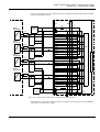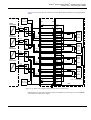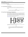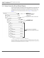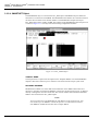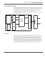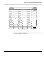
1
Advant® Smart Device (HART®) Interface User’s Guide Table of Contents TABLE OF CONTENTS Chapter 1 - Introduction 1.1 General Information................................................................................................. 1-1 1.2 Equipment Requirements......................................................................................... 1-1 1.3 How to Use This Book............................................................................................. 1-2 1.4 Conventions ............................................................................................................. 1-3 1.5 Related Documentation............................................................................................ 1-4 1.6 Release History ........................................................................................................ 1-4 1.7 Terminology............................................................................................................. 1-4 1.8 Product Overview .................................................................................................... 1-5 Chapter 2 - Installation 2.1 General Information................................................................................................. 2-1 2.2 Setup ........................................................................................................................ 2-1 2.2.1 Connecting to an Advant Controller 410 Subsystem.............................. 2-2 2.2.1.1 2.2.2 2.3 Connecting to an Advant Controller 460 .............................................. 2-11 Smart Device Setup................................................................................................ 2-15 2.3.1 2.4 CI532V02, MVI for ModbusB(inary).............................. 2-3 Connecting to a SHIM .......................................................................... 2-18 2.3.1.1 SHIM Power................................................................... 2-19 2.3.1.2 SHIM Serial Port Connections....................................... 2-19 2.3.1.3 Setting SHIM ModbusB Slave Address......................... 2-20 2.3.1.4 Setting SHIM Parity and Baud Rate .............................. 2-21 2.3.1.5 Smart Device Connections ............................................. 2-22 2.3.1.6 Digital Signals Only....................................................... 2-23 2.3.1.7 Analog and Digital Signals ............................................ 2-23 2.3.1.8 Power Considerations..................................................... 2-38 2.3.1.9 Special Wiring Considerations....................................... 2-38 Smart Device Data Storage Considerations........................................................... 2-38 2.4.1 Setup Information for Smart Devices ................................................... 2-39 2.4.2 Configuration Entries for Smart Devices.............................................. 2-39 2.4.3 Techniques of Mapping Smart Device Variables to Advant OCS ........ 2-39 Chapter 3 - Configuration 3.1 Design Considerations ............................................................................................. 3-1 3.1.1 Advant Smart Device Interface Configuration Procedures..................... 3-1 3.2 Capacity and Performance ....................................................................................... 3-1 3.3 Configuration Building ............................................................................................ 3-1 3.3.1 3BUR 001 085R0001 REV A Advant Controller 460 and Related Objects ........................................... 3-2 i Advant® Smart Device (HART®) Interface User’s Guide Table of Contents CONTENTS (continued) 3.3.2 Advant Controller 410 and Related Objects ........................................... 3-4 3.3.3 Advant Controller Objects ...................................................................... 3-6 3.3.4 3.3.5 3.4 3.3.3.1 AC460............................................................................... 3-6 3.3.3.2 AC460MOD ..................................................................... 3-7 3.3.3.3 AC410............................................................................... 3-9 MVI Module and Port Planning............................................................ 3-10 3.3.4.1 MVIBOARD .................................................................. 3-11 3.3.4.2 MVI_PORT .................................................................... 3-13 Configuration of Smart Device (PLC) Parameters................................ 3-18 3.3.5.1 PLC Object ..................................................................... 3-18 3.3.5.2 PLC_PORT Object ......................................................... 3-20 3.3.5.3 PLC_DEF Object ........................................................... 3-22 3.3.5.4 SMARTNET Object ....................................................... 3-26 Application Building.............................................................................................. 3-28 3.4.1 CCF Templet ......................................................................................... 3-28 3.4.2 Configuration of Advant OCS Loops that Support Smart Devices....... 3-28 3.4.3 Loop Definition and FCM Templets ..................................................... 3-29 3.4.4 FCM Input Templet............................................................................... 3-32 Chapter 4 - Runtime Operation 4.1 Product Operation .................................................................................................... 4-1 4.2 Operating Overview ................................................................................................. 4-3 4.3 ii 4.2.1 I/O ........................................................................................................... 4-3 4.2.2 Start-up .................................................................................................... 4-4 4.2.2.1 Coordination Signals ........................................................ 4-4 4.2.2.2 Scanner Task..................................................................... 4-4 4.2.2.3 Output Request Task......................................................... 4-5 4.2.2.4 Transmitter Task ............................................................... 4-5 4.2.2.5 Receiver Task.................................................................... 4-5 Runtime Displays ..................................................................................................... 4-5 4.3.1 Display Hierarchy ................................................................................... 4-5 4.3.2 Accessing Runtime Transmitter Displays ............................................... 4-6 4.3.3 Smart Device Network Overview Display .............................................. 4-9 4.3.4 Smart Device I/O Display ..................................................................... 4-11 4.3.5 Smart Device Tuning Overview Display............................................... 4-12 4.3.5.1 Tuning Smart Devices via the Smart Device Tuning Overview Display ........................................................... 4-13 4.3.5.2 Runtime Parameter Change Logging ............................. 4-14 3BUR 001 085R0001 REV A Advant® Smart Device (HART®) Interface User’s Guide Table of Contents CONTENTS (continued) Chapter 5 - Maintenance 5.1 Introduction.............................................................................................................. 5-1 5.2 Hardware Indicators................................................................................................. 5-1 5.3 5.2.1 CI532V02 MVI Submodule LEDs ......................................................... 5-1 5.2.2 SHIM Indicators ..................................................................................... 5-1 Error Messages ........................................................................................................ 5-2 5.3.1 5.4 Diagnostic Messages............................................................................... 5-2 Fault Finding and User Repair................................................................................. 5-3 5.4.1 User Repair ............................................................................................. 5-4 5.4.1.1 Board and Subrack Mounted Unit Replacement.............. 5-4 5.4.1.2 Smart Device Removal and Installation Procedures ........ 5-5 Appendix A - PLC Directory References A.1 3BUR 001 085R0001 REV A PLC Reference Objects............................................................................................A-1 A.1.1 PLC_AB Initial Data Base......................................................................A-2 A.1.2 PLC_MODBUS Initial Data Base ..........................................................A-3 A.1.3 PLC_COMMON Initial Data Base.........................................................A-4 A.1.4 PLCTYPES Initial Data Base .................................................................A-5 iii Advant® Smart Device (HART®) Interface User’s Guide Table of Contents iv 3BUR 001 085R0001 REV A Advant® Smart Device (HART®) Interface User’s Guide Chapter 1 Introduction 1.1 General Information This instruction book is a guide for configuring the Advant® Smart Device (HART®) Interface which allows you to connect smart devices to an Advant Controller. Information on planning, organizing, and entering data base parameters from the Structure Builder are explained in detail. Also described are other data base configuration entries necessary to provide support for the interface. This book is not intended to be the sole source of instruction for Advant Smart Device (HART) Interface software. Those people involved in system engineering should attend the applicable system engineering courses offered by ABB. 1.2 Equipment Requirements The Advant Smart Device (HART) Interface is part of the Advant Controller 410 or Advant Controller 460 subsystem and is used to view and manipulate variables from attached smart devices. An Advant Controller 410 can be equipped with one or two MultiVendor Interface (MVI) modules which have two RS-232 serial ports each, for a total of 4 ports. Communication is provided by connections between these modules and the SHIMs (Small HART Interface Module) that connect to smart devices. An Advant Controller 460 can have 3 CPUs with each CPU having one to four MVI modules with two RS-232 serial ports each, for a total of 8 ports. Communication is provided by connections between these modules and the SHIMs that connect to smart devices. Chapter 2, Installation, of this manual provides information about the types of connections needed between the smart devices and the system. 3BUR 001 085R0001 REV A 1-1 Advant® Smart Device (HART®) Interface User’s Guide Chapter 1 Introduction 1.3 How to Use This Book This book is organized into chapters and sections as shown in Figure 1-1. Chapter Introduction Installation Configuration Runtime Operation Considerations Product Operation Capacity & Operating Equipment Performance Overview Requirements Configuration How to Use Building Smart Device This Book Mapping Application Considerations Conventions Smart Device Building Data Storage Related Run Time Considerations Documentation Displays Release History General Information General Information Setup Advant Cont. Smart Device Setup Maintenance Appendices Index Introduction Hardware Indicators Error Messages Fault Finding & User Repair Section Terminology Product Overview Figure 1-1. Organization of Manual Chapter 1, Introduction presents an overview of the Advant Smart Device (Hart) Interface and its use within the Advant OCS. Chapter 2, Installation, lists the types of smart devices supported, describes how to connect them to the Advant Controller, and gives specific configuration information for each type supported. Chapter 3, Configuration explains how to set up the portion of the system data base that supports the interface. This portion includes items necessary to support communication between smart devices and Configurable Control Function (CCF) loops. Chapter 4, Runtime Operation describes the operation of the Advant Smart Device (Hart) Interface. Chapter 5, Maintenance explains configuration-related error codes returned by the smart device interface to the Advant OCS and reported as diagnostic messages. 1-2 3BUR 001 085R0001 REV A Advant® Smart Device (HART®) Interface User’s Guide Section 1.4 Conventions 1.4 Conventions The following conventions are used throughout this manual for the presentation of material: • The words in proper names of screen elements (for example, the title in the title bar of a window, the label for a field of a dialog box) are initially capitalized. • The names of keyboard keys are boldfaced. – Initial capital letters are used for the name of a keyboard key if it is labeled on the keyboard. For example, the Return key or <Return>. – Lowercase letters are used for the name of a keyboard key that is not labeled on the keyboard. For example, the space bar, comma key, and so on. – In descriptions, the word “key” is used in conjunction with its name. For example, pressing the Return key initiates the process. – In tables and procedures, angle brackets replace the word “key.” For example, press <Return>. – A dash is used to indicate that you must simultaneously press several keys. For example, <CTRL-C> indicates that you must hold down the CTRL key while pressing the C key. – The phrase “press and release” is used to indicate that you sequentially press several keys. For example, to count the hits in a Template Builder, press and release <ESC>, and then <C>. This indicates that you press and release the ESC key, and then you press and release the C key. • • • The names of push and toggle buttons are boldfaced. – Initial capital letters are used for the name of a push or toggle button labeled on the display. For example, the OK button. – In descriptions, tables and procedures, the word “button” is used in conjunction with its name. For example, pressing the OK button initiates the process. The names of menus and menu items are boldfaced. – Initial capital letters are used for the name of menus listed in the menu bar. For example, the File menu. – Initial capital letters are used for the name of menu items. For example, to open a new window, choose New from the File menu. System prompts/messages are shown in the Courier font, and user responses/input are in the boldfaced Courier font. For example, if you enter a value out of range, the following message is displayed: Entered value is not valid. The value must be 0-30. In a tutorial, you may be told to enter the string TIC132 in a field. The string is shown as follows in the procedure: TIC132 3BUR 001 085R0001 REV A 1-3 Advant® Smart Device (HART®) Interface User’s Guide Chapter 1 Introduction 1.5 Related Documentation Other instruction books applicable to PC interface configuration include: • AdvaBuild Basic Functions User’s Guide • Configurable Control Functions (CCF) • Advant Controller 410 User’s Guide • Advant Controller 460 User’s Guide Also refer to the smart device manufacturer’s documentation applicable to configuration. 1.6 Release History Table 1-1 lists the major milestones in the development of Advant Smart Device (Hart) Interface. Table 1-1. Release History Version 1.0 Description Advant Smart Device (Hart) Interface 1.7 Terminology Object An object is a logical representation of plant equipment, a location, documentation, or software function in the project database. For instance: • A GENERICD object represents a subsystem in the Advant OCS • a TSTRUC object represents an area in the plant • a PI_DIA object represents a P&I diagram • a PID object represents a PID algorithm Definitions 1-4 • HART Highway Addressable Remote Transmitter • SHIM Small HART Interface Module • MVI Multivendor Interface Board • C1 Carrier Module SC510 (used to hold MVI board) • SI Software Interface to the MVI board • AC 410 Advant Controller 410 • AC 460 Advant Controller 460 3BUR 001 085R0001 REV A Advant® Smart Device (HART®) Interface User’s Guide Section 1.8 Product Overview • MTU Mounting Termination Unit for S800 I/O modules • Connection Unit Field termination device for S100 I/O boards • TRIO Taylor Remote I/O blocks 1.8 Product Overview The Advant Smart Device (Hart) Interface is a software module resident in the CPU of the Advant Controller 410 (AC 410) and Advant Controller 460 (AC 460). It provides a method for CCF and TLL to have access to raw input values from a smart device, and a method for sending parameters to the smart device. The Advant Smart Device (HART) Interface allows an Advant Controller to read or write data to smart devices or other compatible devices. Data is mapped into CCF points for control purposes. Advant Controller 460 MVI RS232 TRIO Fieldbus 4-20mA (HART) Smart Transmitter SHIM TRIO Block Figure 1-2. Advant Smart Device (HART) Interface Overview The Smart Device Interface software provides digital signal processing of transmitter data from the field for diagnostic, monitoring and tuning functions, thereby allowing the operator or instrumentation technician to perform maintenance and tuning functions normally done in the field from the control room. Error reporting is also provided through the standard Advant OCS diagnostics to inform the operator of potential problems with a transmitter in the field. 3BUR 001 085R0001 REV A 1-5 Advant® Smart Device (HART®) Interface User’s Guide Chapter 1 Introduction Conventional transmitters communicate with the Advant OCS via a 4-20 mA analog signal proportional to the process variable being measured. This 4-20 mA signal requires analog to digital conversion for the digitally based Advant OCS host to measure, display and control the measured process variable. Smart devices (HART-compatible transmitters) can communicate with the Advant OCS via analog and digital signals. Analog signals from smart devices are communicated in the same manner as conventional devices, via a 4-20 mA signal. Smart devices digitally communicate range limits and maintenance information in addition to the process variable with the Advant OCS host via HART protocol using Frequency Shift Keying (FSK). Since the FSK signal does not compromise the 4-20 mA signal of a smart device, the analog (4-20 mA) signal and digital (FSK) signal for a smart device can co-exist on the same physical twisted pair of wires. To convert the HART FSK current to voltage which the SHIM can read, a dropping resistor is used. The permitted range of the HART loop resistance is from 230 ohms to 1100 ohms. Typically, a 250 ohm resistor is used. NOTE If connection units (S100 I/O), MTUs (S800 I/O) or TRIO blocks are not used for SHIMs communicating only digital signals, a 250 ohm 1% 5W resistor is required to provide the 250 ohm loop resistance. When both analog and digital communication with smart devices is desired, the analog signal is brought to the Advant controller using either S100 I/O, S800 I/O or Taylor Remote I/O (TRIO). Digital signals from up to four or eight smart devices are AC coupled from the smart devices using a SHIM purchased from Arcom Control Systems, Inc. The SHIM facilitates communication between the smart devices and the Advant OCS by converting the HART protocol used by the smart devices to the ModbusB protocol used by the Advant OCS. The SHIM also converts the HART protocol physical/link layers signals to RS-232 (optionally to RS-485 with converter) signal levels respectively used for Advant Controller serial communication. An AC410 node can be equipped with either one or two CI532V02 ModbusB Multi-vendor Interface(s) (MVI), which have two ports each. Each RS-232 port is provided by connection between these modules, a SHIM, and up to eight smart devices connected to each SHIM. If an RS-232 to 485 converter is used, then up to 31 SHIMs can be connected to a port with up to eight smart devices connected to each SHIM, depending on performance requirements. An AC 460 node can have up to three redundant PM510 CPU sets with up four CI532V02 ModbusB Multi-vendor Interface(s) (MVI) per PM510 CPU set. Each RS-232 port is provided by connection between these modules, a SHIM, and up to eight smart devices connected to each SHIM. If an RS-232 to 485 converter is used, then up to 31 SHIMs can be connected to a port with up to eight smart devices connected to each SHIM, depending on performance requirements. NOTE Communications redundancy for the Smart Device Interface is not available, therefore, there is no automatic port switching upon failure of the Advant OCS to SHIM connection. 1-6 3BUR 001 085R0001 REV A Advant® Smart Device (HART®) Interface User’s Guide Section 1.8 Product Overview The data base used by the interface is downloaded when the interface is powered-up or reset. After a Smart Device Interface configuration is downloaded, data tables (CCF channel tables) are allocated for analog and digital input values read from the smart devices. Channel assignments relate to a particular smart device 16-bit word (register) or 1-bit (coil) instead of hardware connections. Periodic scanning of the smart device data by the SHIM commences at a rate of three times per second. During a scan, commands requesting data are sent to each smart device. More than one command may be required in order to read all required data. Information concerning what and how much data is read is obtained from Smart Device Interface configuration tables. If a handheld monitor is placed on-line with a smart device, the rate at which the SHIM scans smart device data drops to one time per second. CCF Continuous Loop CCF Data Base Smart Device Interface The smart devices respond to each command by sending back the requested data. The smart device configuration then specifies how the smart device data is stored in the CCF control loop. Figure 1-1 shows an example of the smart device/CCF communication scheme. CCF accesses values read from smart devices based on the input channel specified for each loop. Analog Input Other FCMs Figure 1-1. Smart Device/CCF Loop Communication Scheme When a smart device fails to respond to two consecutive commands, a message is generated informing the operator of a smart device communications failure and the data qualities of loops associated with the smart device are set to BAD. The software continues to attempt to communicate with the smart device without generating further messages. No communication is initiated by a smart device. Only responses to Advant OCS initiated commands are accepted. Transfer of smart device variables to the Advant OCS data base via CCF loops that receive the variables can provide the following functions within the Advant OCS: • Processing of smart device variables by the CCF loops that receive them, or by other CCF loops. • Trending of smart device variables. • Interaction with TCL programs. • Inclusion of smart device variables in reports produced by the Report Services software. • Inclusion of smart device variables in displays produced by the Display Builder software. • Storing of smart device variables by the Historical Services software. • Generation and logging of alarms for smart device variables. 3BUR 001 085R0001 REV A 1-7 Advant® Smart Device (HART®) Interface User’s Guide Chapter 1 Introduction 1-8 3BUR 001 085R0001 REV A Advant® Smart Device (HART®) Interface User’s Guide Chapter 2 Installation 2.1 General Information The Advant Smart Device (HART) Interface can run in an Advant Controller and supports communication to smart devices. Different models of smart devices are supported depending on the subsystem configuration. Information about the Advant Controller configurations supported by the Advant Smart Device (HART) Interface and the smart devices they support is provided in the sections that follow. 2.2 Setup The Advant Controller communicates via RS-232 serial connections to smart devices. The smart devices are connected to an Arcom Control Products SHIM-4 or SHIM-8. The SHIMs are then either connected directly to the Advant Controller’s MVI via an RS-232 connection or they are connected to either a Black Box IC108A RS-232 to RS-485/422 Converter Plus or a Westermo Teleindustri AB MA-42 Converter RS-232 to RS-485/422 which in turn is connected to the Advant Controller. Arcom Control Systems, Black Box and Westermo contact information follows: Table 2-1. Arcom Control Systems Inc. Contact Information Arcom Control Systems Inc. 13510 South Oak Street Kansas City, MO 248145 (816) 941-7025 Voice (816) 941-0343 FAX Table 2-2. Black Box Contact Information Black Box P.O. Box 12800 Pittsburgh, PA 15241 (412) 746-5500 Voice Order Line 7AM to 8PM ET M-F 8AM to 4PM ET Sat. (800) 321-0746 FAX - 24 hours (412) 746-0746 FAX - 24 hours http://www.blackbox.com 3BUR 001 085R0001 REV A 2-1 Advant® Smart Device (HART®) Interface User’s Guide Chapter 2 Installation Table 2-3. Westermo Teleindustri Contact Information Westermo Teleindustri AB S-640 40 Stora Sundby Sweden +46 16 61200 Voice +46 16 61180 FAX Has distributors in: Norway, Finland, Denmark, Austria, Belgium, France, Netherlands, Switzerland, Germany, Great Britain & Italy. Table 2-4 lists the smart devices supported in an Advant Controller. Table 2-4. Smart Devices Supported in an Advant Controller Communication Protocol Manufacturer/Model Connection ABB Instruments Inc. KSC/1K1322010030 Differential Pressure ModbusB Point to point ModbusB Point to point Rosemont 1151 Differential Pressure 3044C Temperature 3051C Differential Pressure NOTE The smart devices listed in Table 2-4 are subject to change without notice 2.2.1 Connecting to an Advant Controller 410 Subsystem The paragraphs that follow describe the serial ports of an Advant Controller 410 (AC410) and how to connect a smart device to them. AC410 Ports The serial ports of an AC410 are provided by the MVI module which is installed in the PM150 CPU. A PM150 can contain one or two of the MVI modules. Each MVI module uses one submodule position, and provides two serial ports. MVI module 1 contains serial ports 3/1 and 3/2, and MVI module 2 contains ports 4/3 and 4/4. The communications protocol must be the same for both ports on the same MVI submodule. Separate versions of the MVI support specific communication protocols. The communications protocols are implemented in firmware on the MVI module. Therefore, the appropriate protocol must be specified when ordering the MVI option. 2-2 3BUR 001 085R0001 REV A Advant® Smart Device (HART®) Interface User’s Guide Section 2.2.1 Connecting to an Advant Controller 410 Subsystem 2.2.1.1 CI532V02, MVI for ModbusB(inary) The CI532V02 MVI module (used for the smart device interface) shown in Figure 2-1 contains two 9-pin male connectors. The pin designations for the connectors are listed in Table 2-5. The SHIMs (or RS-232/485 converters) are connected to the CI532V02 MVI module via RS-232 serial cables with a 9-pin connector. CI 532 F R RUN-LED FAULT-LED CHANNEL 1 (X4) CHANNEL 2 (X5) Figure 2-1. CI532V02 MVI Module The CI532V02 MVI Module does not have any user jumper that need to be set. Table 2-5. Pin Designation for Channel 1 and 2, Connector X4 and X5 3BUR 001 085R0001 REV A Pin Name Description 1 DCD 2 RD Receive Data 3 TD Transmit Data 4 DTR Data Terminal Ready 5 GND Ground 6 DSR Data Set Ready 7 RTS Request To Send 8 CTS Clear To Send 9 RI Ring Indicator Data Carrier Detect 2-3 Advant® Smart Device (HART®) Interface User’s Guide Chapter 2 Installation MVI to SHIM (RS-232) for an Advant Controller 410 For RS-232 communication, an MVI serial port is connected to a single SHIM in a point-to point fashion using a single RS-232 cable as shown in Figure 2-2. Each SHIM can be connected to as many as 8 HART transmitters. PM150 MVI CI532V02 XMTR SHIM 1-8 Port 4/3 (RS-232) XMTR 3BUC950040R001 Figure 2-2. RS-232 Communications to a Smart Device in an AC410 Up to 4 SHIMs can be connected to the MVIs of the PM150. The MVI is configured: • 9600 baud, 8N1 (8 data bits, no parity, 1 stop bit), full-duplex. The 3BUC950040R001 cable (8 meters) between the MVI serial port (RS-232) and the SHIM-8 has the following pin assignments: Table 2-6. MVI Serial Port to SHIM Cable, 3BUC950040R001 MVI DTE 9-pin Female D connector SHIM XTB1 (unterminated) Description 1,4 - DCD is jumpered to DTR 2 3 RD 3 4 TD 5,6 2-4 5 7 GND 6,7,8 - RTS is jumpered to DSR and CTS 3BUR 001 085R0001 REV A Advant® Smart Device (HART®) Interface User’s Guide Section 2.2.1 Connecting to an Advant Controller 410 Subsystem Figure 2-3 shows an example of the 3BUC950040R0001 cable used to connect a SHIM device to an Advant Controller via the 9-pin connector on the MVI module. 9-pin D Connector, female CI532V02 MVI Module DCD RD TD DTR GND DSR RTS CTS RI 1 2 3 4 5 6 7 8 9 XTB1 3 4 5 6 7 TD RD SHIM-4/8 GND Figure 2-3. 3BUC950040R0001 Cable for Connecting a SHIM to the CI532V02 MVI The SHIM-4/8 is also configured to be 9600 baud, 8N1 which is its default setting. The SW2 18 settings are OFF, OFF, ON, OFF, ON, ON, OFF, OFF. The SHIM PROM is version 3.03 or later. Always refer to the documentation that comes with the equipment for more information. 3BUR 001 085R0001 REV A 2-5 Advant® Smart Device (HART®) Interface User’s Guide Chapter 2 Installation MVI to RS-232/485 Converter to SHIM (RS-485) for an Advant Controller 410 This configuration is used to connect an MVI serial port to as many as 31 SHIMs in a multidrop fashion using an RS-232/485 converter. Each SHIM-8 can be connected to up to 8 HART transmitters for a total of 248 possible HART transmitters (Figure 2-4). PM150 RS-232/485 converter MVI CI532V02 XMTR Port 4/3 (RS-232) 1-8 SHIM No.1 XMTR 3BUC900041R0001 RS-485 SHIM No.2 SHIM No. 31 Figure 2-4. RS-232/485 Communications to a Smart Device in an AC410 Up to four RS-232/485 converters can be connected to the MVIs of the PM150. The MVI is configured: • 2-6 9600 baud, 8N1, half-duplex. 3BUR 001 085R0001 REV A Advant® Smart Device (HART®) Interface User’s Guide Section 2.2.1 Connecting to an Advant Controller 410 Subsystem The 3BUC900041R0001 cable (8 meters) between the MVI serial port and the RS-232/485 converter has the following pin assignments: Table 2-7. 3BUC900041R0001 MVI Serial Port to RS-232/485 Converter Cable Description RS-232/485 Converter MVI DTE(1) 9-pin Female D connector 25-pin Male D connector RD 2 3 TD 3 2 DTR 4 20 GND 5 7 DSR 6 6 RTS 7 4 CTS 8 5 (1) Pins 1 and 9 are not used/connected. The Black Box IC108A is configured in the following manner: Table 2-8. Black Box IC108A Set-up Requirements Function Switch/Jumper Settings Configure RS-232 port as DCE XW1 in position A RTS/CTS/CD delay W5 in position A-B Signal ground not connected to frame ground W7 is OUT Half-duplex operation (2-wire) W8 in position B-C RTS/CTS delay - 0ms W9 in position C RS-485 driver is RS-232 RTS/CD enabled W15 in position A-B Half-duplex turnaround delay - 0.1ms W16 in position B RS-485 Driver Enable Hold - 7ms W17 in position B Normal Operation S1 in OUT position RS-485 Receiver Terminated S2 in ON position RS-485 Line Bias ON S3 in ON position Always refer to the documentation that comes with the equipment for more information. 3BUR 001 085R0001 REV A 2-7 Advant® Smart Device (HART®) Interface User’s Guide Chapter 2 Installation The Westermo Teleindustri AB MA-42 is configured in the following manner: Table 2-9. Westermo Teleindustri AB MA-42 Set-up Requirements Function Switch Settings Selection of power source 115V/230V AC S1 is set according to local AC requirement Transmitter activated by RTS CTS controlled by RTS DCD controlled by RTS CTS Delay = 20ms S2 1,4,6 = ON 2,3,5 = OFF 2-wire Line Connection and Termination S3 2,5,6 = ON 1,3,4 = OFF Always refer to the documentation that comes with the equipment for more information. The twisted-pair RS-485 cable between the RS-232/485 converter and the first SHIM connection has the following pin assignments: Table 2-10. RS-232/485 Converter to First SHIM Cable (RS-485) Westermo Teleindustri AB Black Box IC108A SHIM MA-42 Line Connection Description TB1 (unterminated) XTB1 (unterminated) (5-position screw terminal) 1,3 RxB, TxB 8 Data + 2,4 RxA, TxA 9 Data - Each subsequent SHIM on the RS-485 bus is daisy-chained to each other using a twisted-pair wire connecting XTB1-8 to XTB1-8 and XTB1-9 to XTB1-9 of each SHIM. 2-8 3BUR 001 085R0001 REV A Advant® Smart Device (HART®) Interface User’s Guide Section 2.2.1 Connecting to an Advant Controller 410 Subsystem The last SHIM in the RS-485 bus must have a 100-ohm 1/8W resistor inserted across XTB1-8 and XTB1-9 to terminate the RS-485 bus. IC108A - TB1 SHIM - XTB1 SHIM - XTB1 RxA 8 8 RxB 9 TxA Internal Termination TxB DATA+ DATA- 9 100-ohm Termination resistor 1200 meters maximum 1 meter minimum Figure 2-5. Black Box IC108A to SHIM RS-485 Wiring Diagram MA-42 Line Connection SHIM - XTB1 SHIM - XTB1 3 8 8 4 9 1 Internal Termination 2 DATA+ DATA- 9 100-ohm Termination resistor 1200 meters maximum 1 meter minimum Figure 2-6. Westermo Teleindustri AB MA-42 to SHIM RS-485 Wiring Diagram The SHIM-4/8 is also configured to be 9600 baud, 8N1 which is its default setting. The SW2 18 settings are OFF, OFF, ON, OFF, ON, ON, OFF, OFF. The SHIM PROM version was 3.03. Always refer to the documentation that comes with the equipment for more information. 3BUR 001 085R0001 REV A 2-9 Advant® Smart Device (HART®) Interface User’s Guide Chapter 2 Installation The maximum length of the RS-485 bus is 1200 meters (3,937 feet) and the shortest possible drop (stub) length is 1 meter (3.3 feet). 1200 meters maximum RS-232/485 Converter SHIM - XTB1 SHIM - XTB1 8 8 1 meter minimum 9 8 9 DATA+ DATA- 9 DATA+ DATA- Figure 2-7. RS-485 Typical 2-Wire Connection Diagram 2-10 3BUR 001 085R0001 REV A Advant® Smart Device (HART®) Interface User’s Guide Section 2.2.2 Connecting to an Advant Controller 460 2.2.2 Connecting to an Advant Controller 460 The paragraphs that follow describe the serial ports of an Advant Controller 460 (AC460) and how to connect a smart device to them. The smart device interface can take advantage of CPU redundancy. AC460 CPU Redundancy The AC460 CPU (PM510) can be either non-redundant as shown in Figure 2-8, or it can use CPU redundancy as shown in Figure 2-9. If CPU redundancy is used, the backup CPU takes over processing if the primary CPU fails. All functions of the primary CPU including smart device support are handled by the backup CPU. Information about AC460 redundancy is provided in the Advant Controller 460 User’s Guide. NOTE Redundancy of CPUs and smart device communications are independent functions. In the event of a takeover by the back-up CPU, there is no corresponding fail-over of the serial ports. CPU 3/B CPU 3/A CPU 2/B Empty Slot CPU 1/A AC460 Subrack CPU 2/A CI CI PM PM CI CI PM PM CI CI CI CI 510 510 510 510 510 510 510 510 510 510 540 540 PM 510 MVI CI532V02 PM510K01 Non-Redundant CPU XMTR SHIM Port 3/4 (RS-232) 1-8 XMTR Figure 2-8. AC460 without PM510 CPU Redundancy 3BUR 001 085R0001 REV A 2-11 Advant® Smart Device (HART®) Interface User’s Guide Chapter 2 Installation CPU 3/B CPU 3/A CPU 2/B CPU 2/A CPU 1/B AC460 Subrack CPU 1/A PM PM CI CI PM PM CI CI PM PM CI CI CI CI 510 510 510 510 510 510 510 510 510 510 510 510 540 540 MVI CI532V02 PM510K02 Redundant CPU XMTR SHIM Port 3/4 (RS-232) 1-8 XMTR Figure 2-9. AC460 with PM510 CPU Redundancy AC460 Serial Ports The serial ports of an AC460 are provided by the MVI module. Each MVI has two serial ports that are set up for RS-232 communication. If the smart device uses a different electrical interface, a converter box must be provided. Separate versions of the MVI support specific smart device protocols. The protocols are implemented in firmware on the MVI module. Therefore, the appropriate protocol must be specified when ordering the MVI option. • CI532V02, MVI for ModbusB(inary) The CI532V02 MVI module as shown in Figure 2-1 contains two 9-pin male connectors. The pin designations for the connectors are listed in Table 2-5. The SHIMs (or RS-232/485 converters) are connected to the CI532V02 MVI module via RS-232 serial cables with 9-pin connectors. 2-12 3BUR 001 085R0001 REV A Advant® Smart Device (HART®) Interface User’s Guide Section 2.2.2 Connecting to an Advant Controller 460 An Advant Controller 460 CPU (PM510) can support up to four MVI submodules for a total of eight serial ports, Figure 2-10. AC460 Controller Subrack Serial Port 3/1 Serial Port 3/2 Serial Port 4/5 Serial Port 4/6 Serial Port 3/3 Serial Port 3/4 Serial Port 4/7 Serial Port 4/8 CI532V02 Figure 2-10. Advant Controller 460 Connection to MVI MVI to SHIM (RS-232) for an Advant Controller 460 For RS-232 communication, an MVI serial port is connected to a single SHIM in a point-to point fashion using a single RS-232 cable as shown in Figure 2-11. CPU 1/B CPU 1/A PM PM 510 510 MVI CI532V02 XMTR SHIM Port 4/7 (RS-232) 1-8 XMTR Figure 2-11. RS-232 Communications to a Smart Device in an AC460 Up to 8 SHIMs can be connected to each CPU of the AC 460. The MVI settings, cabling, and SHIM settings are the same as for the AC 410. 3BUR 001 085R0001 REV A 2-13 Advant® Smart Device (HART®) Interface User’s Guide Chapter 2 Installation MVI to RS-232/485 Converter to SHIM (RS-485) for an Advant Controller 460 This configuration is used to connect an MVI serial port to as many as 31 SHIM-8s in a multidrop fashion using an RS-232/485 converter. Each SHIM-8 can be connected to up to 8 HART transmitters for a total of 248 possible HART transmitters (Figure 2-12). PM PM 510 510 CPU 1/B CPU 1/A RS-232/485 converter MVI CI532V02 XMTR Port 4/7 (RS-232) SHIM No.1 1-8 XMTR RS-485 SHIM No.2 SHIM No. 31 Figure 2-12. RS-232/485 Communications to a Smart Device in an AC460 Up to 8 RS-232/485 converters can be connected to each CPU of the AC 460. The MVI settings, cabling, RS-232/485 converter settings and SHIM settings are the same as for the AC 410 2-14 3BUR 001 085R0001 REV A Advant® Smart Device (HART®) Interface User’s Guide Section 2.3 Smart Device Setup 2.3 Smart Device Setup Prior to connecting smart devices to the Advant OCS, you must initially configure them using an external device such as a PC-based configuration package (not supplied with the Smart Device Interface) or a hand-held monitor like the ones shown in Figure 2-13 and 2-2 (KentTaylor KHT1 and Rosemount Model 268). During initial configuration, you must specify the unique tag name and transmitter polling address for each smart device you want to connect to the Advant OCS. The tag name is used when establishing initial communication with a smart device to obtain its unique identifier. The transmitter polling address you specify for each smart device should be 0 (zero), allowing for the communication of both analog and digital signals by the smart device. If you specify an address other than 0, the analog signal is not generated with the digital signal. See the documentation for the PC-based configuration package or hand-held monitor you are using for instructions on how to configure smart devices. NOTE Hand-held monitors can later be used to tune smart devices in the field, however, any tuning changes made with the hand-held monitor are not logged by the Advant OCS. 3BUR 001 085R0001 REV A 2-15 Advant® Smart Device (HART®) Interface User’s Guide Chapter 2 Installation Kent-Taylor F1 F2 F3 F4 KHT1 ON PV OFF REVIEW CONF. SERIAL LINK ENTER TRIM ESCAPE 7 8 9 4 5 6 1 2 3 0 . + - Figure 2-13. Kent-Taylor Hand Held Monitor 2-16 3BUR 001 085R0001 REV A Advant® Smart Device (HART®) Interface User’s Guide Section 2.3 Smart Device Setup Rosemount F1 F2 F3 F4 Rosemount HART Communications SMART FAMILY INTERFACE ON PROCESS VARIABLE REVIEW HELP RESTART PREVIOUS FUNCTION ABC DEF GHI 7 8 9 OFF JKL MNO PQR 4 5 6 STU VWX YZ# 1 2 3 @ % & SPACE 0 268 . +/* _ SHIFT SHIFT SHIFT ALPHABET/SYMBOLS Figure 2-14. Rosemount HART Communications SMART FAMILY INTERFACE 3BUR 001 085R0001 REV A 2-17 Advant® Smart Device (HART®) Interface User’s Guide Chapter 2 Installation 2.3.1 Connecting to a SHIM The MVI serial ports support ModbusB protocol. The smart devices use HART protocol. Therefore, to communicate information to the Advant Controller, the HART protocol of smart devices must be converted to ModbusB protocol. This conversion is provided by a Small HART Interface Module (SHIM). The Smart Device Interface supports 2 SHIM models: SHIM-4 and SHIM-8. You can connect up to 4 smart devices to a SHIM-4 and up to 8 smart devices to a SHIM-8. In the remainder of this document, the term SHIM refers to either the SHIM-4 or SHIM-8. The terms SHIM-4 and SHIM-8 only are used to identify information specific to that model Both the SHIM-4 and SHIM-8 have a 10-position terminal block (XTB1) and two 12-position terminal blocks (XTB2 and XTB3) as shown in Figure 2-15. However, there are no internal connections for the second 12-position terminal block (XTB3) on the SHIM-4. Diagnostic LEDs XTB1 RUN LED 1 2 3 4 5 6 7 8 9 10 Fuse XTB3 XTB2 12 11 10 9 8 7 6 5 4 3 2 1 1 2 3 4 5 6 7 8 9 10 11 12 Figure 2-15. Front and Right Side View of SHIM 2-18 3BUR 001 085R0001 REV A Advant® Smart Device (HART®) Interface User’s Guide Section 2.3.1 Connecting to a SHIM In addition to the terminal blocks on the SHIM’s front panel, there is a red LED and a fuse. The LED flashes to signal that the SHIM passed its self test and is running. The fuse is a 0.5 Amp Excitation fuse which is shared by all smart devices connected to the SHIM to protect their Excitation connections. There are also two other red diagnostic LEDs visible from the top of the SHIM’s housing. If either of these LEDs is flashing, an error has been detected. See Section 5.2, Hardware Indicators for information about the errors the diagnostic LEDs indicate. Signal designations for the contact positions of the SHIM terminal blocks and their use are provided in Table 2-11. Table 2-11. SHIM Terminal Block Designations XTB1 Contact Signal XTB2 Use Contact Signal XTB3 (SHIM-8 ONLY) Use Contact Signal 1 +24 VDC Power 12 EXCITATION Smart Device 1 1 SIGNAL- 2 COM Ground 11 SIGNAL+ 2 SIGNAL+ 3 TX 10 SIGNAL- 3 EXCITATION 4 RX RS-232 Serial Port 9 EXCITATION Smart Device 2 4 SIGNAL- 5 RTS 8 SIGNAL+ 5 SIGNAL+ 6 CTS 7 SIGNAL- 6 EXCITATION 7 COM 6 EXCITATION Smart Device 3 7 SIGNAL- 8 DATA+ 5 SIGNAL+ 8 SIGNAL+ 9 DATA- 4 SIGNAL- 9 EXCITATION 10 COM 3 EXCITATION Smart Device 4 10 SIGNAL- 2 SIGNAL+ 11 SIGNAL+ 1 SIGNAL- 12 EXCITATION RS-485 Serial Port Use Smart Device 8 Smart Device 7 Smart Device 6 Smart Device 5 2.3.1.1 SHIM Power SHIMs are powered by a small AC/DC power supply. The physical power and ground connections from the power supply are made at the screw terminations XTB1-1 and XTB1-2 of the SHIM as indicated in Table 2-11. 2.3.1.2 SHIM Serial Port Connections As indicated in Table 2-11, terminal block XTB1 also has contacts for 2 serial ports which independently communicate ModbusB protocol using either RS-232 or RS-485. Connections between the MVI serial ports and the serial port contacts on a SHIM are made using either the 3BUC900040R0001 MVI to SHIM Interface Cable or 3BUC900041R0001 MVI to RS-232/485 Converter Interface Cable. The 3BUC900040R0001 MVI to SHIM Interface Cable connects an MVI RS-232 port to a SHIM RS-232 serial port. Connection to the serial port is made with a female connector, and 3BUR 001 085R0001 REV A 2-19 Advant® Smart Device (HART®) Interface User’s Guide Chapter 2 Installation connection to the SHIM RS-232 serial port is made using screw terminations XTB1-3, XTB1-4, and XTB1-7, see Figure 2-3. NOTE Contacts XTB1-5 and XTB1-6 of the SHIM RS-232 serial port support connection of a modem to the SHIM, and are jumpered together. The 3BUC900041R0001 MVI to RS-232/485 Converter Interface Cable connects an MVI RS232 port to the RS-232/485 converter. Cabling from the converter’s RS-485 port to the RS-485 port of the first SHIM on the RS-485 Bus is not supplied by ABB. You can then daisy chain up to 31 SHIM RS-485 serial ports on a RS-485 Bus. The SHIM to SHIM RS-485 serial port interconnections on the RS-485 Bus are shown in Table 2-12. Table 2-12. SHIM to SHIM RS-485 Interconnections on RS-485 Bus SHIM RS-485 Serial Port SHIM RS-485 Serial Port Contact Signal Contact Signal XTB1-8 DATA + XTB1-8 DATA + XTB1-9 DATA - XTB1-9 DATA - NC Shield NC Shield NOTE The SHIM RS-485 serial port contacts allow you to replace a SHIM without disrupting the RS-485 Bus. 2.3.1.3 Setting SHIM ModbusB Slave Address Each SHIM connected on the RS-485 Bus must have a different ModbusB slave address. The SHIM ModbusB slave address is set on a 8-position DIP switch labeled S1 which is accessible from the back panel of the SHIM’s 6U cassette housing as shown in Figure 2-16. The first switch position (S1-1) has a binary weight of 1 when ON (towards the number on the DIP switch). The second through eighth switch positions (S1-2 through S1-8) have respective binary weights of 2, 4, 8, 16, 32, 64, and 128 when ON. If a switch position is OFF (away from the number on the DIP switch), it has a binary weight of 0. Only SHIM ModbusB slave addresses 1 through 31 are supported, therefore, only positions S1-1 through S1-5 are used to set SHIM ModbusB slave addresses and positions S1-6 through S1-8 are always set to OFF. 2-20 3BUR 001 085R0001 REV A Advant® Smart Device (HART®) Interface User’s Guide Section 2.3.1 Connecting to a SHIM S1 12345678 S2 12345678 Figure 2-16. DIP Switches Accessible from Back Panel of SHIM You can purchase SHIMs with their ModbusB slave addresses preset by ABB. The preset address is indicated on a sticker on the side of the SHIM’s housing, thereby, allowing you to easily locate a particular SHIM in the field. If you purchased SHIMs without preset ModbusB slave addresses or you want to change a SHIM’s address, set switch positions S1-1 through S15 to the ON or OFF setting that produces the desired address and write the address on the sticker on the side of the SHIM housing. For example, to set a SHIM’s ModbusB slave address to 2, switch positions S1-1 through S1-5 are set to OFF, ON, OFF, OFF, and OFF, respectively. The SHIM in Figure 2-16 has a ModbusB slave address of 2. 2.3.1.4 Setting SHIM Parity and Baud Rate HART protocol communicates smart device field data to the SHIM at 1200 baud, and ModbusB protocol communicates at 9600 baud. Therefore, to support ModbusB protocol for the communication of smart device field data to the Advant Controller, SHIM serial ports are configured at 9600 baud with no parity by default. The SHIM serial port baud rate and parity are 3BUR 001 085R0001 REV A 2-21 Advant® Smart Device (HART®) Interface User’s Guide Chapter 2 Installation can be set on the 8-position DIP switch labeled S2 which is accessible from the back panel of the SHIM’s housing as shown in Figure 2-16. The first and second switch positions (S2-1 and S2-2) are set to OFF, indicating parity of None. The third through fifth switch positions (S2-3 through S2-5) are respectively set to ON, OFF, and ON, indicating a baud rate of 9600. Switch positions S2-6 through S2-8 are always set to OFF. Table 2-13 lists the switch position S2-1 through S2-5 settings and the parity and baud rate they set. Table 2-13. DIP Switch Position S2-1 Through S2-5 Settings and Their Corresponding Parity and Baud Rates Parity S2-1 S2-2 Baud Rate S2-3 S2-4 S2-5 None OFF OFF 300 OFF OFF OFF Odd OFF ON 600 ON OFF OFF Even ON OFF 1200 OFF ON OFF Reserved ON ON 2400 ON ON OFF 4800 OFF OFF ON 9600 ON OFF ON 19200 OFF ON ON Reserved ON ON ON 2.3.1.5 Smart Device Connections As indicated in Table 2-11, there are three contacts on SHIM terminal blocks XTB2 and XTB3 for each of the up to eight smart devices you can connect to a SHIM: Excitation, Signal+, and Signal-. Excitation connections are protected by a shared 0.5 Amp Excitation fuse located on the front panel, but there is no current limiting resistor or fuse per Excitation connection. Therefore, if a SHIM powers a smart device loop, an external 50 mA fuse is required on the corresponding SHIM Excitation to smart device Tx+ wire. Otherwise, a blown Excitation fuse takes down all smart device loops powered by the SHIM without affecting serial communication with the SHIM. Digital communication from smart devices is AC coupled to the SHIM on corresponding Signal+ connections, and all Signal- connections to the SHIM are internally shorted together to COM. The physical connection between the screw terminations of a smart device and a SHIM is made using a cable referred to as a HART Bus. See Section 5.4.1.2, Smart Device Removal and Installation Procedures for specific installation and removal information. NOTE The maximum length of the HART Bus is 10,000 ft. (3,048 m) or is determined using the following formula, whichever is less: L = 65,000,000 / (R x C) - (Cf + 10,000) / C where L is the length in feet or meters, R is the total loop resistance in ohms, C is the cable capacitance in pF/ft. or pF/m, and Cf is the sum of CN values of smart 2-22 3BUR 001 085R0001 REV A Advant® Smart Device (HART®) Interface User’s Guide Section 2.3.1 Connecting to a SHIM devices multiplied by 5,000 pF. For smart devices without CN values, use 1. Masters (primary and secondary) need not be counted in deriving Cf. 2.3.1.6 Digital Signals Only Digital signals of smart devices are brought into a Advant Controller via SHIMs connected to the MVI serial ports. For digital communication only with smart transmitters, a SHIM can supply loop power to smart transmitter loops and provide digital communication to MVI port using RS-232 directly or for multiple SHIMs using the RS-485 bus through a RS-232/485 converter. Since analog input termination panels are not used for digital only communication with smart devices connected to a SHIM, a 250 ohm 1% 5W resistor is required. This resistor is needed to provide the 250 ohm HART loop resistance that converts the HART FSK current to a voltage (1V to 5V) that the SHIM can read. NOTE In the field, you can tune a smart device communicating only digital signals to the Advant Controller by attaching a hand-held monitor to its smart transmitter loop using grapper hooks across its terminals or the resistor attached between its corresponding SHIM Signal+ and Signal- connections. Any tuning changes you make to the smart device with the hand-held monitor are not logged by the Advant OCS. 2.3.1.7 Analog and Digital Signals Advant Controllers can support both analog and digital communication with smart devices or just digital communication as described above. The analog signal from a smart device is brought into the Advant Controller using either S100 I/O, S800 I/O or Taylor Remote I/O (TRIO). The digital signal from up to eight smart devices is AC coupled to the SHIM. S100 I/O Analog signals brought into an Advant Controller employing S100 I/O use either DSAI 130 Analog Input boards, DSAI 133 Analog Input boards or DSAX 110 Analog Input/Output Boards. The DSAI 130 has terminations for 16 analog inputs, the DSAI 133 has terminations for 32 analog inputs and the DSAX 110 has terminations for 8 analog inputs. In the AC 410 the S100 I/O boards are installed in its subrack. Up to 15 boards can be installed in the AC 410 subrack. For the AC 460 the information from S100 I/O boards come from separate S100 I/O subracks. Up to 5 subracks can be connected to each CI540 S100 submodule installed in the AC 460. Please refer to the S100 I/O User’s Guide, Advant Controller 410 User’s Guide, and the Advant Controller 460 User’s Guide for more information on S100 I/O connections. Figure 2-17 shows an example of the connections for the AI board, DSAI 130, with 4-20mA inputs. The connection unit DSTA 131, used together with the DSAI 130 board, is provided with screw terminals to connect 16 analog input signals. 3BUR 001 085R0001 REV A 2-23 Advant® Smart Device (HART®) Interface User’s Guide Chapter 2 Installation PROCESS Smart Transmitter External fuse may be required if more than 6 smart transmitters are connected. CONTROLLER + SHIM _ CONNECTION UNIT AI BOARD DSTA 131 DSAI 130 1 X90 CH1A Sig+ 4 - 20 mA W11 R250ohm 2 CH1B + - 18 F1=0.1A ZERO GAIN SYM 17 + 24 Vdc Pwr. Sup. - 20 19 F2 22 21 F3 28 F6 + 30 - 29 W1 Figure 2-17. Connection of AI Board DSAI 130 to DSTA 131 Figure 2-18 shows an example of DSAI 130 board connected to the process with connection unit DSTA 133. The example illustrates a single channel connection of the transmitter. The connection unit DSTA 133 has 16 channels, of which eight are intended only for two-wire transmitter connection and eight are individually adaptable to two-, three- or four-wire transmitter connection. In all cases, the transmitters can be supplied power via a fuse on DSTA 133. Figure 2-19 shows an example of the DSAI 133 board connected to the process with the connection unit DSTA 002. Use the connection unit DSTA 002 together with DSAI 133 to connect 16 unipolar, single-ended current or voltage signals. Two DSTA 002, for 32 channels, are used together with one DSAI 133. You can connect the connection unit to two DSAI 133 for redundancy. Each channel has a voltage output, protected with a PTC resistor, for transmitter power. 2-24 3BUR 001 085R0001 REV A Advant® Smart Device (HART®) Interface User’s Guide Section 2.3.1 Connecting to a SHIM PROCESS CONTROLLER Smart Transmitter + CONNECTION UNIT AI BOARD DSTA 133 DSAI 130 2 SHIM _ 1 Sig+ 4 - 20 mA Singleended To Pwr. Sup. + Smart Transmitter F1 0.1 A CH1 - CH8 18 0.1 A + F9 SHIM _ Sig+ 17 4 - 20 mA To Pwr. Sup. + - ZERO GAIN SYM Singleended CH9 19 Smart Transmitter 39 0.1 A + F16 SHIM _ ZERO GAIN SYM Sig+ 38 4 - 20 mA Singleended + - + 24 Vdc Pwr. Sup. - CH16 40 41 U1 + 42 U2 + 43 U- ZERO GAIN SYM 44 45 46 Figure 2-18. Connection of AI Board DSAI 130 to DSTA 133 3BUR 001 085R0001 REV A 2-25 Advant® Smart Device (HART®) Interface User’s Guide Chapter 2 Installation PROCESS CONTROLLER + 24 Vdc Pwr. Sup. - AI BOARD DSTA 002 DSAI 133 X90 24 V 1 Smart Transmitter 0V 2 + X91 1 SHIM _ CONNECTION UNIT CH1 Sig+ X81 4 - 20 mA 2 W1 0V + X82 3 - 250 F Smart Transmitter + 4 SHIM _ CH2 Sig+ X81 4 - 20 mA 5 W2 0V + X82 6 - 250 F Smart Transmitter + _ X94 10 CH16 Sig+ 4 - 20 mA X81 11 W16 X82 + 12 0V 250 F SHIM X81 COMMON X82 DSTA 002 DSAI 133 (Redundant) CH17 - CH32 X81 X82 Figure 2-19. Single and Redundant Connections of DSAI 133 to DSTA 002 2-26 3BUR 001 085R0001 REV A Advant® Smart Device (HART®) Interface User’s Guide Section 2.3.1 Connecting to a SHIM Figure 2-20 shows an example of the DSAX 110 board connected to the process with the connection unit DSTA 001. You can connect the connection unit to two DSAX 110 for redundancy. CONTROLLER PROCESS + 24 Vdc Pwr. Sup. - CONNECTION UNIT AI BOARD DSTA 001 DSAX 110 X90 1 Smart Transmitter Board 1 24 V 0V 2 + 1 _ Sig+ 4 -20 mA CHAI1 X91 2 X81 W1 + 250 F COMMON X81 SHIM + _ X82 3 Smart Transmitter X2 X82 X92 10 Sig+ 0V 4-20 mA CHAI8 X81 11 W16 + X82 12 - F 250 X81 U+ SHIM 0 - 20 mA X93 CHA01 X82 X81 1 500 Ω RL X82 2 3 Analog Output Signals 0- 10 V X94 10 500 Ω 11 12 RL = 100 k gives ∆U = 0.5% X81 X82 Shunt Jumper RL CHA08 X81 OV X82 DSAX 110 (Redundant) Board 2 X2 Figure 2-20. Connection of AI/O Board DSAX 110 to DSTA 001 3BUR 001 085R0001 REV A 2-27 Advant® Smart Device (HART®) Interface User’s Guide Chapter 2 Installation S800 I/O Analog signals brought into an Advant Controller employing S800 I/O use either AI810 Analog Input modules or AI820 Analog Input modules. The AI810 module has terminations for 8 analog inputs, and the AI820 has terminations for 4 analog inputs. To communicate information from the S800 I/O modules to the Advant Controller, a CI520 Advant Fieldbus 100 (AF 100) submodule is required. The CI520 has connections to the Advant Fieldbus 100 modem that connects to the S800 I/O Stations. Up to 32 I/O Stations can be configured on one AF 100 segment and each S800 I/O Station can have up to 24 I/O modules. Please refer to the S800 I/O User’s Guide, Advant Fieldbus 100 User’s Guide, Advant Controller 410 User’s Guide and the Advant Controller 460 User’s Guide for more information on S800 I/O connections. 2-28 3BUR 001 085R0001 REV A Advant® Smart Device (HART®) Interface User’s Guide Section 2.3.1 Connecting to a SHIM Figure 2-21 shows the process connections for the Analog Input Module AI810 when installed on the Extended MTU TU830. TU830 Process AI810 X2 X1 6.3A + L1+ L1+ L1L1- + 24 Vdc Pwr. Sup. - Smart Transmitter 0.1A Fuse _ Sig+ 4 -20 mA + Smart Transmitter + 0.1A SHIM Fuse _ Sig+ 4 -20 mA + Smart Transmitter + 0.1A _ SHIM Fuse _ L1+ I2U I2I ZP B5,B6 C5 C6 A5,A6 L1+ I3U I3I ZP B7,B8 C7 C8 A7,A8 L1+ I4U I4I ZP L2+ I5U I5I ZP C9 C10 A9,A10 Smart Transmitter 0.1A B3,B4 C3 C4 A3,A4 Sig+ + + L1+ I1U I1I ZP B9,B10 4 -20 mA Sig+ 4 -20 mA L- B1,B2 C1 C2 A1,A2 SHIM Fuse B11,B12 C11 C12 A11,A12 L2+ I6U I6I ZP B13,B14 L2+ I7U I7I ZP L2+ I8U I8I ZP C13 C14 A13,A14 B15,B16 + C15 C16 A15,A16 SHIM 6.3A + 24 Vdc Pwr. Sup. - L1+ Fuse L2+ L2+ L2L2- Fuse Mux. L2+ L- EM Figure 2-21. AI810 with Extended MTU (TU830) Process Connections External fuses to each smart transmitter must be installed to protect the power to other SHIMs connected to the same power supply. 3BUR 001 085R0001 REV A 2-29 Advant® Smart Device (HART®) Interface User’s Guide Chapter 2 Installation Figure 2-22 shows the process connections for the AI810 when installed on the Compact MTU TU810. Process TU810 X1 + 24 Vdc Pwr. Sup. - L1+ L1+ L1- Smart Transmitter + 0.1A Fuse _ 4 -20 mA + Smart Transmitter + SHIM 0.1A Fuse _ Sig+ Sig+ - Smart Transmitter + 0.1A Fuse _ 4 -20 mA + SHIM Smart Transmitter + _ 0.1A Fuse L1+ I2U I2I ZP C3 B3 A3 L1+ I3U I3I ZP C5 B5 A5 L1+ I4U I4I ZP L2+ I5U I5I ZP C6 B6 A6 L2+ I6U I6I ZP Exc Sig+ Sig- Exc 4 -20 mA Sig+ Sig+ SHIM + 24 Vdc Pwr. Pwr. Sup. - ZP C2 B2 A2 C4 B4 A4 SHIM L1+ L1+ I1U I1I ZP Exc 4 -20 mA X2 C1 B1 A1 Exc Sig+ Sig- AI810 C7 B7 A7 C8 B8 A8 L2+ L2+ L2- Mux. L2+ I7U I7I ZP L2+ I8U I8I ZP L2+ ZP EM Figure 2-22. AI810 with Compact MTU (TU810) Process Connections External fuses to each smart transmitter must be installed to protect the power to other SHIMs connected to the same power supply. 2-30 3BUR 001 085R0001 REV A Advant® Smart Device (HART®) Interface User’s Guide Section 2.3.1 Connecting to a SHIM Figure 2-23 shows the process connections for the AI810 when installed on the Extended MTU TU835. Process TU835 + 24 Vdc _ Pwr. Sup. AI810 X2 X12 L1+ L1+ L1L1- Smart Transmitter + L1+ LF1 A1 _ Sig+ Fn=100mA A2 4 -20 mA F2 A3 Smart Transmitter + - + SHIM _ Sig+ A4 F3 A5 A6 4 -20 mA F4 A7 Smart Transmitter + - + SHIM _ Sig+ A8 F5 A9 A10 4 -20 mA A11 Smart Transmitter + - A12 SHIM + _ F6 L1+ I1U I1I ZP L1+ I2U I2I ZP L1+ I3U I3I ZP Mux. L1+ I4U I4I ZP L2+ I5U I5I ZP L2+ I6U I6I ZP F7 A13 Sig+ A14 4 -20 mA F8 A15 + - A16 SHIM + 24 Vdc Pwr. Sup. _ L2+ L2+ L2L2- L2+ I7U I7I ZP L2+ I8U I8I ZP L2+ L- EM Figure 2-23. AI810 with Extended MTU (TU835) Process Connections 3BUR 001 085R0001 REV A 2-31 Advant® Smart Device (HART®) Interface User’s Guide Chapter 2 Installation Figure 2-24 shows the process connections for the Differential Analog Input Module AI820 when installed on the Extended MTU TU830. TU830 6.3A 0.1A Fuse Sig+ Smart Transmitter Sig+ Smart Transmitter Smart Transmitter + _ 4 -20 mA Sig+ + 0.1A L1+ I1I+ I1L1- B5,B6 C5 C6 A5,A6 L1+ I2U+ I2IB L1- B7,B8 C7 C8 A7,A8 L1+ I2I+ I2L1- B9,B10 C9 C10 A9,A10 L2+ I3U+ I3IB L2- B11,B12 C11 C12 A11,A12 L2+ I3I+ I3L2- B13,B14 L2+ I4U+ I4IB L2- Diff. Amp + LPF 250Ω Compensation SHIM Fuse _ B3,B4 C3 C4 A3,A4 Diff. Amp + LPF 250Ω Compensation 4 -20 mA SHIM Fuse C13 C14 A13,A14 Sig+ + SHIM + 24 Vdc Pwr. Sup. _ 4 -20 mA 250Ω Compensation L2+ I4I+ I4L2- B15,B16 C15 C16 A15,A16 6.3A L2+ L2+ L2L2- 250Ω Compensation Fuse L2+ L2- 4W + + 0.1A L1+ I1U+ I1IB L1- SHIM Fuse _ B1,B2 C1 C2 A1,A2 250Ω 0.1A 4 -20 mA L1- 4W + + - L1+ 250Ω _ Fuse 4W L1+ L1+ L1L1- Smart Transmitter + X2 X1 250Ω 24 Vdc Pwr. Sup. _ AI820 4W + 250Ω Process Diff. Amp + LPF Diff. Amp + LPF LPF = Low Pass Filter EM Figure 2-24. AI820 with Extended MTU (TU830) Process Connections External fuses to each smart transmitter must be installed to protect the power to other SHIMs connected to the same power supply. 2-32 3BUR 001 085R0001 REV A Advant® Smart Device (HART®) Interface User’s Guide Section 2.3.1 Connecting to a SHIM Figure 2-25 shows the process connections for the AI820 when installed on the Compact MTU TU810. TU810 + Smart Transmitter + SHIM 0.1A Fuse _ 4 -20 mA Exc Sig+ Sig+ - Smart Transmitter + SHIM 0.1A Fuse _ + - _ SHIM 0.1A Fuse L1+ I1U+ I1IB L1- C2 B2 A2 L1+ I1I+ I1L1- C3 B3 A3 L1+ I2U+ I2IB L1- A4 L1+ I2I+ I2L1- C5 B5 A5 L2+ I3U+ I3IB L2- C6 B6 A6 L2+ I3I+ I3L2- C4 B4 Exc Sig+ Sig- Smart Transmitter + 4 -20 mA C1 B1 A1 4 -20 mA Exc Sig+ Sig- C7 B7 A7 + SHIM 4 -20 mA + 24 Vdc Pwr. Sup. _ C8 B8 A8 L2+ L2+ L2- L2+ I4U+ I4IB L2L2+ I4I+ I4L2- Diff. Amp + LPF Diff. Amp + LPF 250Ω Compensation 250Ω Compensation 250Ω Compensation 250Ω Compensation L2+ L2- 4W Sig+ Sig- L1- 250Ω _ Exc 250Ω 0.1A Fuse L1+ 4W + L1+ L1+ L1- 4W Smart Transmitter X2 250Ω X1 AI820 4W + 24 Vdc Pwr. Sup. _ 250Ω Process Diff. Amp + LPF Diff. Amp + LPF LPF = Low Pass Filter EM Figure 2-25. AI820 with Compact MTU (TU810) Process Connections External fuses to each smart transmitter must be installed to protect the power to other SHIMs connected to the same power supply. 3BUR 001 085R0001 REV A 2-33 Advant® Smart Device (HART®) Interface User’s Guide Chapter 2 Installation TRIO Blocks Analog signals brought into an Advant Controller employing Taylor Remote I/O (TRIO) use either 6230B Analog Input/Output Blocks, 6231B Current Source Analog Input/Output Blocks or 6235B Current Source Analog Input Blocks. The 6230B and 6231B TRIO Blocks have terminations for four analog inputs and the 6235B TRIO Block has terminations for six analog inputs. The analog information for up to 30 TRIO blocks is communicated to the Advant Controller via a TRIO Field Bus. To communicate information from the TRIO blocks to the Advant Controller, a CI560 TRIO submodule is required for each Field Bus. The CI560 has connections on its front panel for the physical connection of the Field Bus to the Advant Controller. Please refer to the Taylor Remote I/O (TRIO) User’s Guide, Advant Controller 410 User’s Guide and the Advant Controller 460 User’s Guide for more information on TRIO connections. NOTE • The 24V dc loop power supply isolation of the 6231B or 6235B Current Source Analog Block is lost because the COM input is common to all the SHIM Signal- inputs. • Configurations using 6231B or 6235B Current Source Analog Blocks require an additional 150 ohm 1% 5W resistor for each smart devices connected to the block. The resistor should be installed between its SHIM Signal+ and TRIO block IN contacts. • To tune a smart device from the field, you can attach a hand-held monitor to its smart transmitter loop using grapper hooks across the corresponding IN and JMP terminals of the 6230B Analog Input/Output Block or IN and COM terminals of the 6231B or 6235B Current Source Analog Block the transmitter is attached to. Any tuning changes you make to the smart device using the hand-held monitor are not logged by the Advant OCS. Figure 2-26 show the typical smart device connections for communication of both analog and digital signals to TRIO. Figure 2-28 shows the wiring for a 6231B Current Source Analog 2-34 3BUR 001 085R0001 REV A Advant® Smart Device (HART®) Interface User’s Guide Section 2.3.1 Connecting to a SHIM Input/Output Block or a 6235B Current Source Analog Input Block, and Figure 2-27 shows the wiring for a 6230B Analog Input/Output Block. To other TRIO blocks on Field Bus (up to 30 per Field Bus) Smart Device Interface Cables Field Bus Contacts of Current Source Analog I/O Block SERIAL 1 1 SERIAL 2 2 SHIELD IN 3 SHIELD OUT 4 GND DC + DC – NC +BSM -BSM OUT RTN GND OUT RTN GND EXC IN COM GND EXC IN COM GND EXC IN COM GND EXC IN COM GND 5 6 7 8 9 10 11 12 13 14 15 16 17 18 19 20 21 22 23 24 25 26 27 28 29 30 31 32 24V POWER OUTPUT 1 OUTPUT 2 INPUT 1 INPUT 2 INPUT 3 INPUT 4 CPU 3/A CPU 3/B CPU 2/A CPU 2/B AC460 Subrack CPU 1/A CPU 1/B PM PM CI CI PM PM CI CI PM PM CI CI CI CI 510 510 510 510 510 510 510 510 510 510 510 510 540 540 Power Supply Distribution +- SHIM-8 (up to 6 per 6U Card File) 6U Card File to 24V Power Supply HART Bus 6231B Current Source Analog I/O Block Smart Devices (up to 8 per SHIM-8) Figure 2-26. Typical Smart Device Connections to TRIO 3BUR 001 085R0001 REV A 2-35 Advant® Smart Device (HART®) Interface User’s Guide Chapter 2 Installation Power Supply + 24 V dc Advant Controller P P Sig+ Sig- SHIM P Tx Rx MVI port RS-232 P 47 + EXC - HART Bus TRIO Field bus 100 COM 150 ohm resistor added to loop resistance Marshalling Strip P 24 V dc IN 150 SMT XMT 6231B or 6235B Analog Block Power Supply Daisy Chain to next SHIM + 24 V dc - Advant Controller P P Sig+ Sig- SHIM P D+ D- RS-232 to RS-485 Conv. RS-485 RS-232 MVI port P - + EXC HART Bus 150 SMT XMT Marshalling Strip 150 ohm resistor added to loop resistance 47 COM P 24 V dc IN TRIO Field bus 100 6231B or 6235B Analog Block Figure 2-27. Smart Device Wired to a TRIO 6231B or 6235B Analog Block The field wiring for the 6231B or 6235B Current Source Analog Blocks require an additional 150 ohm 1% 5W resistor for each smart device connected to the block. The resistor should be installed between its SHIM Signal+ and TRIO block IN contacts. 2-36 3BUR 001 085R0001 REV A Advant® Smart Device (HART®) Interface User’s Guide Section 2.3.1 Connecting to a SHIM Power Supply + 24 V dc Advant Controller P P + - HART Bus Sig+ Sig- SHIM SMT XMT P 50 mA Exc Tx Rx MVI port RS-232 P IN P JMP 250 TRIO Field bus RTN 6230B Analog Input/Output Block Power Supply + 24 V dc - Daisy Chain to next SHIM Advant Controller P P + - HART Bus Sig+ Sig- SHIM SMT XMT P 50 mA Exc D+ D- RS-232 to RS-485 Conv. RS-485 RS-232 MVI port P IN JMP 250 P RTN TRIO Field bus 6230B Analog Input/Output Block Figure 2-28. Smart Device Wired to a TRIO 6230B Analog Input/Output Block The SHIM powers the smart device in Figure 2-28, therefore, an external 50 mA fuse is required between the smart device TX+ and SHIM Excitation connection. This is done to prevent a blown Excitation fuse from taking down all smart transmitter loops powered by the SHIM. 3BUR 001 085R0001 REV A 2-37 Advant® Smart Device (HART®) Interface User’s Guide Chapter 2 Installation 2.3.1.8 Power Considerations The common mode voltage between the SHIM, termination panels, and their power supply cannot exceed 0V dc. 2.3.1.9 Special Wiring Considerations There are several types of intrinsic safety barriers configurations used when operating in environments that require intrinsic safety. Use either shunt-diode safety barriers or isolating repeaters. NOTE You can use most intrinsic safety barriers, provided 2-way digital communication between smart transmitters and the SHIM is not impeded. 2.4 Smart Device Data Storage Considerations This section discusses how the data from smart devices is stored, and suggests a technique you can use in programming or configuring smart devices and in configuring the Smart Device Interface. The technique is intended to optimize the utilization of memory and avoid problems that can make a smart device layout inefficient. In addition, the assigning of CCF channel numbers in the Smart Device Interface is discussed to show the effect of the technique on their usage. A channel should not be used by more than one device. CCF Continuous Loop CCF Data Base Smart Device Interface As Figure 2-29 shows, there is one analog channel table in a AC 410 or AC 460 subsystem to support analog inputs from the smart devices. Analog Input Other FCMs Figure 2-29. Smart Device/CCF Loop Communication Scheme An analog input FCM of a continuous loop can acquire the value of a variable in the analog channel table. It is accessed as an input by one FCM. NOTE An AC 410 or AC 460 subsystem has one analog channel table to support smart device inputs. If one smart device stores its four inputs in analog channels 1 through 4, another smart device should not store its input data in these analog channels. 2-38 3BUR 001 085R0001 REV A Advant® Smart Device (HART®) Interface User’s Guide Section 2.4.1 Setup Information for Smart Devices 2.4.1 Setup Information for Smart Devices Smart devices are connected to the Advant Controller. Section 2.2, Setup, has information about the types of serial connections supported. Configuration of the MVI ports requires entries to the fields in the edit window of the MVIBOARD templet and MVI_PORT templet. The templets are described in Section 3.3.4.1, MVIBOARD and Section 3.3.4.2, MVI_PORT. 2.4.2 Configuration Entries for Smart Devices Entries required for configuring communications with the smart devices are via the PLC Templet, PLC_PORT Templet PLC_DEF Templet and SMARTNET Templet using the AdvaBuild Structure Builder. The methods of using these displays and a description of their entry fields are provided in Section 3.3.5.1, PLC Object, Section 3.3.5.2, PLC_PORT Object, Section 3.3.5.3, PLC_DEF Object and Section 3.3.5.4, SMARTNET Object. 2.4.3 Techniques of Mapping Smart Device Variables to Advant OCS The ModbusB functions supported by the interface for smart devices are listed in Table 2-14. You should check it prior to configuring your smart devices. Table 2-14. Modbus Function Codes — Smart Devices Function Code Description Modbus Function Code 1 Read output coil Modbus Function Code 2 Read input coil Modbus Function Code 3 Read output register Modbus Function Code 4 Read input register Modbus Function Code 5 Write single output coil Modbus Function Code 6 Write single output register Modbus Function Code 15 Write multiple output coil Modbus Function Code 16 Write multiple output register Commands for the PLC Command Templet The following commands are valid entries for smart devices on the PLC Command Templet. Their use is described in the remainder of this section. General information for making entries to the PLC_COMmand Templet is provided in Section 3.3.5.4, SMARTNET Object. DFOA-C Define Output Only Area - Coils DFOA-R Define Output Only Area - Register RIC 3BUR 001 085R0001 REV A Read Input Coil 2-39 Advant® Smart Device (HART®) Interface User’s Guide Chapter 2 Installation ROC Read Output Coil RIR Read Input Register ROR Read Output Register SCAC Scan Complete Acknowledge to a Coil SCAR Scan Complete Acknowledge to a Register Performing Reads and Writes for smart devices Smart devices use the following definitions: Coil is a discrete device. Discrete outputs are called output coils and inputs are called input coils, input statuses, or discrete inputs. Register is an analog device. Analog inputs are called input registers and outputs are called output or holding registers. ModbusB memory locations are listed in Table 2-15. Table 2-15. ModbusB Memory Locations ModbusB Data Type MOD 300 Range in PLC Command Templet Output Coil 1-9999 Input Coil 10001-19999 Input Register 30001-39999 Output Register 40001-49999 The interface software automatically performs Modbus read/write commands to the appropriate SHIM memory locations. Based on Smart transmitter information in the configuration templets. Reading Coils and Registers Four commands are used to read the memory locations: RIC Read Input Coil ROC Read Output Coil RIR Read Input Register ROR Read Output Register Scan Acknowledge Commands The scan acknowledge commands, SCAC and SCAR, are executed only after a read is completed and provide a means to inform the smart device that all its data has been read by writing a “1” value to either the coil or register specified. When a smart device detects the scan 2-40 3BUR 001 085R0001 REV A Advant® Smart Device (HART®) Interface User’s Guide Section 2.4.3 Techniques of Mapping Smart Device Variables to Advant OCS acknowledgment, it can overwrite the data image table it maintains with fresh data. This technique is especially useful for reading digital data rapidly. Writing to Coils or Registers There are four methods to write to coils and registers: • ROC, Read Output Coil • ROR, Read Output Register • DFOA-C, Define Output Only Area - Coil • DFOA-R, Define Output Only Area - Register 3BUR 001 085R0001 REV A 2-41 Advant® Smart Device (HART®) Interface User’s Guide Chapter 2 Installation 2-42 3BUR 001 085R0001 REV A Advant® Smart Device (HART®) Interface User’s Guide Chapter 3 Configuration 3.1 Design Considerations This chapter describes the AdvaBuild structure builder templets required to support the Advant Smart Device (HART) Interface. General information for using the structure builder is provided in the AdvaBuild Basic Functions User’s Guide. 3.1.1 Advant Smart Device Interface Configuration Procedures The basic steps required for configuring a Smart Device (HART) Interface are: 1. Plan the Smart Device Interface configuration carefully, referring to the smart device manufacturer’s instructions as well as to this document and the related documents it references. 2. Configure the smart devices that are to exchange analog and digital information with the Advant Smart Device (HART) Interface. NOTE Initial configuration of smart devices must be done prior to installing them in the field. This is achieved using an external device such as a PC-based configuration package (not supplied with the interface) or a hand-held monitor. During initial configuration, you must specify the unique tag name and transmitter polling address for each smart device connected to a SHIM. The tag name is used when establishing initial communication with a smart device to obtain its unique identifier. The transmitter polling address you specify for each smart device should be 0 (zero), allowing for the communication of both analog and digital signals by the smart device. If you specify an address other than 0, the analog signal is not generated with the digital signal. 3. Use the structure builder to complete the configuration of the system. The configuration of the smart device part of the data base is described in Section 3.3, Configuration Building. Remember to include the CCF loops that interact with the smart devices. 3.2 Capacity and Performance The Advant OCS system can do 10 read/write commands or 250 words (2 byte words) per second to a ModbusB device. 3.3 Configuration Building Smart devices are connected to the Advant OCS System via an Advant Controller 460 and/or an Advant Controller 410. 3BUR 001 085R0001 REV A 3-1 Advant® Smart Device (HART®) Interface User’s Guide Chapter 3 Configuration 3.3.1 Advant Controller 460 and Related Objects An Advant Controller 460 is represented in the Advant OCS database by an AC460 object. This object is a child of the AREA object and represents a subsystem in the area. Each CPU in the Advant Controller 460 must be represented by an AC460MOD object. The children of the AC460MOD object determine the functionality of that CPU (for example, CCF, S100, TRIO, MVI, PLC and so on). This database hierarchy is shown in Figure 3-1 and described in Table 3-1. AREA Object represents an area in the Advant OCS database AC460 Object represents an Advant Controller 460 AC460MOD Object represents a CPU Children objects of AC460MOD determine the functionality of that CPU Figure 3-1. AC460 Hierarchy Related to AREA Object The AC460 database object is inserted into the Advant OCS database hierarchy and its object attributes are defined via the AdvaBuild Structure Builder and Template Builder respectively (as described in the AdvaBuild Basic Functions User’s Guide). 3-2 3BUR 001 085R0001 REV A Advant® Smart Device (HART®) Interface User’s Guide Section 3.3.1 Advant Controller 460 and Related Objects The Controller (AC460) and related objects are listed in Table 3-1. Table 3-1. Advant Controller 460 Related Objects OBJECT TYPE PURPOSE REFERENCE Advant Controller 460 User’s Guide AC460 Child of AREA object. Establishes one Advant Controller subsystem under a configuration area. AC460MOD Child of AC460 object. One required per CPU (nonAdvant Controller 460 User’s redundant module or redundant pair), up to 3 per Guide subsystem. Establishes basic operating parameters for each CPU group. CCF Child of AC460MOD object. Required for control B130 - Configurable Control modules that support Configurable Control Functions Functions. (CCF). Establishes basic CCF operating parameters for the module, particularly the base processing rate upon which individual loop processing rates are based. AC_TRIO Child of AC460MOD object. Required for control modules that support Taylor Remote I/O. Advant Controller 460 User’s Guide S100_IO Child of AC460MOD object. Required for control modules that support S100 I/O. Advant Controller 460 User’s Guide MVIBOARD Child of AC460MOD object. Required for control This instruction book, Section modules that support serial I/O devices such as a PLC. 3.3.4.1, MVIBOARD. MVI_PORT Child of the MVIBOARD object. Required to define the This instruction book, Section operating parameters of each port on the MVI module. 3.3.4.2, MVI_PORT. PLC Child of AC460MOD object. Required for control modules that support PLC and smart devices. This instruction book, Section 3.3.5.1, PLC Object PLC_PORT Child of PLC object. Required to define the MVI port that will be used. This instruction book, Section 3.3.5.2, PLC_PORT Object PLC_DEF Child of the PLC_PORT object. Required to describe the SHIM addressing of and related items for each device. This instruction book, Section 3.3.5.3, PLC_DEF Object SMARTNET This instruction book, Section Child of the PLC_DEF object. Required to define the correlation between the smart device connected to the 3.3.5.4, SMARTNET Object SHIM and the CCF channel numbers. LL_DEV Child of AC460MOD object. Required for control modules that run Taylor Ladder Logic software. B170 - Taylor Ladder Logic. TCL_RUN Child of AC460MOD object. Required for control modules that run Taylor Control Language (TCL). B160 - Taylor Control Language 3BUR 001 085R0001 REV A 3-3 Advant® Smart Device (HART®) Interface User’s Guide Chapter 3 Configuration Table 3-1. Advant Controller 460 Related Objects (Continued) OBJECT TYPE PURPOSE REFERENCE TCL_MBOX Child of TCL_RUN object. One required for each mailbox being established for a control module. B160 - Taylor Control Language UNITMAST Child of AC460MOD object. Required for control modules that run Taylor Control Language (TCL). B160 - Taylor Control Language 3.3.2 Advant Controller 410 and Related Objects An Advant Controller 410 is represented in the Advant OCS database by an AC410 object. This object is a child of the AREA object and represents a subsystem in the area. The PM150 Control Module in the Advant Controller 410 must be represented by an AC410 object. The children of the AC410 object determine the functionality of the CPU (for example, CCF, S100, TRIO, MVI, PLC and so on). This database hierarchy is shown in Figure 3-2 and described in Table 3-2. AREA Object represents an area in the Advant OCS database AC410 Object represents an Advant Controller 410 Control Module Children objects of AC410MOD determine the functionality of that CPU Figure 3-2. AC410 Hierarchy Related to AREA Object The AC410 database object is inserted into the Advant OCS database hierarchy and its object attributes are defined via the AdvaBuild Structure Builder and Template Builder respectively (as described in the AdvaBuild Basic Functions User’s Guide). 3-4 3BUR 001 085R0001 REV A Advant® Smart Device (HART®) Interface User’s Guide Section 3.3.2 Advant Controller 410 and Related Objects The Controller (AC410) and related objects are listed in Table 3-2. Table 3-2. Advant Controller 410 Related Objects OBJECT TYPE PURPOSE REFERENCE AC410 Child of AREA object. Establishes one Advant Controller Advant Controller 410 User’s Guide subsystem under a configuration area. CCF Child of AC410 object. Required for control modules that B130 - Configurable Control support Configurable Control Functions (CCF). Functions. Establishes basic CCF operating parameters for the module, particularly the base processing rate upon which individual loop processing rates are based. AC_TRIO Child of AC410 object. Required for control modules that Advant Controller 410 User’s Guide support Taylor Remote I/O. S100_IO Child of AC410 object. Required for control modules that Advant Controller 410 User’s support S100 I/O. Guide MVIBOARD Child of AC410 object. Required for control modules that This instruction book, Section support serial I/O devices such as a PLC. 3.3.4.1, MVIBOARD. MVI_PORT Child of the MVIBOARD object. Required to define the operating parameters of each port on the MVI module. PLC Child of AC410 object. Required for control modules that This instruction book, Section support PLC devices. 3.3.5.1, PLC Object PLC_PORT Child of PLC object. Required to define the MVI port that This instruction book, Section will be used. 3.3.5.2, PLC_PORT Object PLC_DEF Child of the PLC_PORT object. Required to describe the This instruction book, Section SHIM addressing of and related items for each device. 3.3.5.3, PLC_DEF Object SMARTNET Child of the PLC_DEF object. Required to define the correlation between the smart device connected to the SHIM and the CCF channel numbers. LL_DEV Child of AC410 object. Required for control modules that B170 - Taylor Ladder Logic. run Taylor Ladder Logic software. TCL_RUN Child of AC410 object. Required for control modules that B160 - Taylor Control Language run Taylor Control Language (TCL). TCL_MBOX Child of TCL_RUN object. One required for each mailbox B160 - Taylor Control Language being established for a control module. UNITMAST Child of AC410 object. Required for control modules that B160 - Taylor Control Language run Taylor Control Language (TCL). 3BUR 001 085R0001 REV A This instruction book, Section 3.3.4.2, MVI_PORT. This instruction book, Section 3.3.5.4, SMARTNET Object 3-5 Advant® Smart Device (HART®) Interface User’s Guide Chapter 3 Configuration 3.3.3 Advant Controller Objects 3.3.3.1 AC460 This object represents an Advant Controller 460 subsystem in the Advant OCS database, Figure 3-3. This object has the following configurable attributes: Figure 3-3. AC460 Object TEMPLET NAME The templet name is required on all templets in the Template Builder. Give the AC460 templet a name that contains up to 21 characters. The name must be unique system wide. PHYSICAL DEVICE This is the DCN node address. This must be the decimal equivalent of the hex address set on the SC540 Carrier Module in the subsystem. Be sure to enter the decimal equivalent value in the Physical Device address field. It can be at any physical address from 2 to 255 decimal. 3-6 3BUR 001 085R0001 REV A Advant® Smart Device (HART®) Interface User’s Guide Section 3.3.3 Advant Controller Objects 3.3.3.2 AC460MOD Each PM510 CPU group (non-redundant module or redundant pair) in the AC460 subsystem must be represented by an AC460MOD object, Figure 3-4. This object has the following configurable attributes: Figure 3-4. AC460MOD Object TEMPLET NAME The templet name is required on all templets in the Template Builder. Give the AC460MOD templet a name that contains up to 21 characters. The name must be unique system wide. PHYSICAL DEVICE This field specifies the location of the CPU group (non-redundant PM510K01 or redundant PM510K02) in the subrack. Valid entries are: 1, 2, or 3. Entry 1 is for the CPU(s) located in slots 1 and 2. Entry 2 is for the CPU(s) located in slots 5 and 6. Entry 3 is for the CPU(s) located in slots 9 and 10. NOTE The redundant CPU pair is automatically configured by the hardware for proper operation. 3BUR 001 085R0001 REV A 3-7 Advant® Smart Device (HART®) Interface User’s Guide Chapter 3 Configuration SOFTWARE NAME Field This field specifies the software downloaded to the controller at start-up. Valid entries are: AC460. Default is: AC460 DO RATE Field The DO RATE field specifies the minimum resolution of any pulse output for the controller. For pulse train outputs, the pulse width and pulse interval as specified through the PO CHANNEL NUMBER edit window of the Controller I/O Templet must be multiples of the DO Rate. For pulse duration outputs, the duration value calculated by the Pulse Duration FCM is rounded to the next lower multiple of the DO Rate. Valid entry is: a number of milliseconds as either 20, 40, 100, 200, or 1000 Default is: 20 NOTE Digital inputs are scanned at one half the DO RATE. This is important because using the DO RATE default value of 20 ms when no pulse outputs are present will lead to a high CPU load. The scan rate for smart devices is not affected by the DO RATE field. 3-8 3BUR 001 085R0001 REV A Advant® Smart Device (HART®) Interface User’s Guide Section 3.3.3 Advant Controller Objects 3.3.3.3 AC410 The Control Module in the Advant Controller 410 subsystem must be represented by a AC410 object, Figure 3-4. This object has the following configurable attributes: Figure 3-5. AC410 Object TEMPLET NAME The templet name is required on all templets in the Template Builder. Give the AC410 templet a name that contains up to 21 characters. The name must be unique system wide. PHYSICAL DEVICE This is the DCN node address. This must be the decimal equivalent of the hex address set on the CS512 DCN Interface submodule. Be sure to enter the decimal equivalent value in the field. It can be at any physical address from 2 to 255 decimal. SOFTWARE NAME Field This field specifies the software downloaded to the controller at start-up. Valid entries are: AC410 Default is: AC410 3BUR 001 085R0001 REV A 3-9 Advant® Smart Device (HART®) Interface User’s Guide Chapter 3 Configuration DO RATE Field The DO RATE field specifies the minimum resolution of any pulse output for the controller. For pulse train outputs, the pulse width and pulse interval as specified through the PO CHANNEL NUMBER edit window of the Controller I/O Templet must be multiples of the DO Rate. For pulse duration outputs, the duration value calculated by the Pulse Duration FCM is rounded to the next lower multiple of the DO Rate. Valid entry is: a number of milliseconds as either 20, 40, 100, 200, or 1000 Default is: 20 NOTE Digital inputs are scanned at one half the DO RATE. This is important because using the DO RATE default value of 20 ms when no pulse outputs are present will lead to a high CPU load. The scan rate for smart devices is not affected by the DO RATE field. 3.3.4 MVI Module and Port Planning The serial port parameters are specified on MVIBOARD and MVI_PORT objects. Each SHIM connected to smart device requires a serial channel for which you define parameters via these objects. An Advant Controller 410 is equipped with either one or two MVI modules depending upon the number of serial ports required. A MVIBOARD Templet must be completed for each MVI module and an MVI_PORT Templet for each port of the MVI module. An Advant Controller 460 can have up to 4 MVI modules (8 serial ports). One MVIBOARD Templet is required for each MVI module and an MVI_PORT Templet for each port of the MVI module. 3-10 3BUR 001 085R0001 REV A Advant® Smart Device (HART®) Interface User’s Guide Section 3.3.4 MVI Module and Port Planning 3.3.4.1 MVIBOARD Four is the maximum number of MVIBOARD objects you can configure for any given controller CPU of an AC460 and 2 for an AC410. The purpose of this object is to associate an MVI submodule with a carrier module and/or its submodule position. The example defines an MVI submodule for this AC 460 CPU to be associated with module location 4, and submodule 1 with a ModbusB protocol. Figure 3-6 is an example of the MVIBOARD object templet view. This object has the following configurable attributes: Figure 3-6. MVIBOARD Templet TEMPLET NAME The templet name is required on all templets in the Template Builder. Give the MVIBOARD templet a name that contains up to 21 characters. The name must be unique system wide. MODULE NUMBER AC410: Enter the slot number (1) for the position of the PM150 on the backplane. AC460: Enter the slot number (3, 4, 7, 8, 11, or 12) for the position of the SC510 Carrier Module in the backplane. The Default value is 3. 3BUR 001 085R0001 REV A 3-11 Advant® Smart Device (HART®) Interface User’s Guide Chapter 3 Configuration SUBMODULE NUMBER AC410: Enter the number 3 (left) or 4 (right) corresponding to where the MVI is installed in the PM150 Control Module. AC460: Enter a number from 1(top) to 2 (bottom) corresponding to where the MVI module is installed in the SC510 Carrier Module. The Default value is 1. PROTOCOL Enter the protocol type depending on the MVI submodule installed and protocol required. The possible entries are: GENERIC for CI532V05 MVI TERMCHAR for CI532V05 MVI ALLENBRADLEY for CI532V04 MVI MODBUSB for CI532V02 MVI <- used for SHIMs MODBUSPLUSfor CI537V01 MVI NOTE Each type of MVI submodule has a special PROM set to run the various protocols. The protocol configured above must be set to match the submodule’s characteristics. Associated with each MVIBOARD object is the MVI_PORT object that defines the characteristics of each port on the MVI module. See Section 3.3.4.2, MVI_PORT for information on how to define each port. 3-12 3BUR 001 085R0001 REV A Advant® Smart Device (HART®) Interface User’s Guide Section 3.3.4 MVI Module and Port Planning 3.3.4.2 MVI_PORT Two is the maximum number of MVI_PORT objects you can configure for any CI532 MVI submodule. The AC410 can have up to 4 MVI_PORTs and each AC460MOD (PM510) can have up to 8 MVI_PORTs defined. This object is a child of the MVIBOARD object and is used to define the operating parameters of a port on a MVI submodule. The example defines port number 5 of the third MVI submodule. Figure 3-7 is an example of the MVI_PORT object templet view. This object has the following configurable attributes: Figure 3-7. MVI_PORT Templet TEMPLET NAME The templet name is required on all templets in the Template Builder. Give the MVI_PORT templet a name that contains up to 21 characters. The name must be unique system wide. This name is used by the PLC_PORT object (Section 3.3.5.2, PLC_PORT Object) to define which port is to be used. 3BUR 001 085R0001 REV A 3-13 Advant® Smart Device (HART®) Interface User’s Guide Chapter 3 Configuration PORT NUMBER Enter the port number on the MVI module that is to be defined. AC410: MVI module in Submodule 3 - upper connector is port 1 and lower connector is port 2. MVI module in Submodule 4 - upper connector is port 3 and lower connector is port 4. AC460: (Per PM510 CPU location) Carrier Module 1 - Submodule 1 - upper connector is port 1 and lower connector is port 2. Carrier Module 1 - Submodule 2 - upper connector is port 3 and lower connector is port 4. Carrier Module 2 - Submodule 1 - upper connector is port 5 and lower connector is port 6. Carrier Module 2 - Submodule 2 - upper connector is port 7 and lower connector is port 8. The Default value is 1. SPEED Use the List function key (<F4>) to list the possible values of the BAUD rate for the serial I/O device the port will be communicating with. Use the Up Arrow or Down Arrow keys to highlight the speed wanted, then press the Accept function key (<F8>) to enter the value in the field. The initial default value is 9600. The possible values are: 150 300 600 1200 2400 4800 9600 <- used for SHIMs 19200 38400 DATA BITS Use the List function key (<F4>) to list the possible values for the DATA BITS size required by the serial I/O device. Use the Up Arrow or Down Arrow keys to highlight the value wanted, then press the Accept function key (<F8>) to enter the value in the field. The initial default value is 8. The possible values are: 5 6 7 8 <- used for SHIMs 3-14 3BUR 001 085R0001 REV A Advant® Smart Device (HART®) Interface User’s Guide Section 3.3.4 MVI Module and Port Planning PARITY Use the List function key (<F4>) to list the possible values for the PARITY data required by the serial I/O device. Use the Up Arrow or Down Arrow keys to highlight the value wanted, then press the Accept function key (<F8>) to enter the value in the field. The initial default value is NONE. The possible values are: NONE <- used for SHIMs ODD EVEN SPACE MARK STOP BITS Use the List function key (<F4>) to list the possible values for the number of STOP BITS required by the serial I/O device. Use the Up Arrow or Down Arrow keys to highlight the value wanted, then press the Accept function key (<F8>) to enter the value in the field. The initial default value is 1. The possible values are: .5 1 <- used for SHIMs 1.5 2 INPUT TIMEOUT Enter the INPUT TIMEOUT value in milliseconds or seconds (see note) that the MVI will wait for the completion of an input operation before an error code is generated. The initial default value is 0. The possible values are: 0 to 999 Enter 500 for SHIMs. NOTE Units are in milliseconds for ModbusB. OUTPUT TIMEOUT Enter the OUTPUT TIMEOUT value in milliseconds or seconds (see note) that the MVI will wait for the completion of an output operation before an error code is generated. The initial default value is 0. The possible values are: 0 to 999 Enter 6 for SHIMs. NOTE Units are in milliseconds for ModbusB. 3BUR 001 085R0001 REV A 3-15 Advant® Smart Device (HART®) Interface User’s Guide Chapter 3 Configuration TERMINATION CHAR(S) Enter the termination character(s) that is used with TERMCHAR protocol types. It is used to specify, in ASCII(hex) code, up to three termination characters (field length = 6). The initial default value is 0D0A (carriage return, line feed). No entry needed for SHIMs. NUMBER OF RETRANSMIT Enter the number of re-transmissions of data after an error. The initial default value is 3. The possible values are: 0 to 10 Enter 1 for SHIMs. CHARACTER TIMEOUT Enter the CHARACTER TIMEOUT value in milliseconds. GENERIC and TERMCHAR must be set to 0. The CHARACTER TIMEOUT for Allen Bradley is 6. The initial default value is 0. The possible values are: 0 to 255 Enter 6 for SHIMs. MODE Use the List function key (<F4>) to list the possible MODEs that the MVI will operate in with the serial I/O device. Use the Up Arrow or Down Arrow keys to highlight the value wanted, then press the Accept function key (<F8>) to enter the value in the field. The initial default value is MASTER. The possible values are: MASTER <- used for SHIMs SLAVE 3-16 3BUR 001 085R0001 REV A Advant® Smart Device (HART®) Interface User’s Guide Section 3.3.4 MVI Module and Port Planning DUPLEX Use the List function key (<F4>) to list the possible method of communications that will be used with the serial I/O device. Use the Up Arrow or Down Arrow keys to highlight the value wanted, then press the Accept function key (<F8>) to enter the value in the field. The initial default value is HALF The possible values are: HALF FULL HALF-NO-DCD for SHIMs use: FULL for RS-232 to SHIM HALF for RS-485 to SHIM NETWORK Enter the requirement for a network definition. The initial default value is 0 (no). The possible values are: 0 (no) <- used for SHIMs 1 (yes) 3BUR 001 085R0001 REV A 3-17 Advant® Smart Device (HART®) Interface User’s Guide Chapter 3 Configuration 3.3.5 Configuration of Smart Device (PLC) Parameters The parameters of each smart device that will be connected to each Advant Controller are defined by four objects: PLC, PLC_PORT, PLC_DEF and SMARTNET. 3.3.5.1 PLC Object The PLC object is a child of the AC410 object or of an AC460MOD object. Only one (1) PLC object can be defined per parent object. The PLC defines the global variables which the PLC package needs to run. The example of the PLC object templet view is shown in Figure 3-8. This object has the following configurable attributes: Figure 3-8. PLC Templet TEMPLET NAME The templet name is required on all templets in the Template Builder. Give the PLC templet a name that contains up to 21 characters. The name must be unique system wide. DESCRIPTION Enter a descriptive name for this Smart Device (PLC) operation. The description can be up to 50 characters. 3-18 3BUR 001 085R0001 REV A Advant® Smart Device (HART®) Interface User’s Guide Section 3.3.5 Configuration of Smart Device (PLC) Parameters BASE SCAN RATE Enter the base scan rate of the PLC scanner (in seconds). This is the rate at which the scanner function processes requests. It is the fastest that any command can be processed. The range for this entry is 0.2 (200 ms) to 600.0 seconds. Default = 1 second. Enter 1 for SHIMs. GOOD DATA WAIT Enter the maximum time to wait at start-up for a full set of commands to complete. When this time has expired, CCF is allowed to continue processing. Range for this entry is 5 to 60 seconds. Default = 15. Enter 60 for SHIMs. MAX READ WAIT Enter the maximum base rate periods to wait before forcing a set of reads. This is needed because data writes have precedent over reads. Range for this entry is 5 to 60 scans. Default = 15. EXAMPLE: (MAX READ WAIT) x (BASE SCAN RATE) = Total Read Wait Time in seconds 15 x 10 = 150 seconds Enter 15 for SHIMs. 3BUR 001 085R0001 REV A 3-19 Advant® Smart Device (HART®) Interface User’s Guide Chapter 3 Configuration 3.3.5.2 PLC_PORT Object The PLC_PORT object is a child of the PLC object. One PLC_PORT object is needed for each MVI port with SHIMs attached. The PLC_PORT defines which MVI port to use as defined in an MVI_PORT object. The example of the PLC_PORT object templet view is shown in Figure 3-8. This object has the following configurable attributes: Figure 3-9. PLC_PORT Templet TEMPLET NAME The templet name is required on all templets in the Template Builder. Give the PLC_PORT templet a name that contains up to 21 characters. The name must be unique system wide. DESCRIPTION Enter a descriptive name for this PLC_PORT as it is being used. The description can be up to 50 characters. 3-20 3BUR 001 085R0001 REV A Advant® Smart Device (HART®) Interface User’s Guide Section 3.3.5 Configuration of Smart Device (PLC) Parameters PROTOCOL Enter the protocol type depending on the MVI submodule installed and protocol required. The possible entries are: GENERIC for CI532V05 MVI TERMCHAR for CI532V05 MVI ALLENBRADLEY for CI532V04 MVI MODBUSB for CI532V02 MVI <- used for SHIMs NOTE Each type of MVI submodule has a special PROM set to run the various protocols. The protocol configured above must be set to match the submodule’s characteristics. PORT NAME Enter the Templet Name for the MVI_PORT object that this PLC_PORT will be connected to. Refer to Figure 3-7 for an example of the templet name of an MVI_PORT. NOTE Do not configure multiple PLC_PORT objects associated with the same MVI_PORT name. BACKUP PORT NAME Enter the Templet Name for the MVI_PORT object that is the back-up port for redundant communications that this PLC_PORT will be connected to. If this field is left blank, then there is no back-up port defined. Refer to Figure 3-7 for an example of the templet name of an MVI_PORT. Leave blank for SHIMs. INTERFACE ADDR This is used for data highways, and is the address of the interface between the serial port and the data highway. Smart devices do not have interface address modules defined, so this value should be left at the default value (1). Default = 1. Enter 1 for SHIMs. BACKUP INT ADDR This is the back-up interface board address of the smart device that is used to communicate with the system. Some smart devices do not need back-up interface address modules defined, so this value should be zero(0). Default = 0. Leave blank for SHIMs. 3BUR 001 085R0001 REV A 3-21 Advant® Smart Device (HART®) Interface User’s Guide Chapter 3 Configuration MAX AGE TIMER This value defines the maximum time to wait for a response to a request to a smart device. Range is from 1 to 32000 seconds. Default = 10. Enter 10 for SHIMs. 3.3.5.3 PLC_DEF Object The PLC_DEF object is a child of the PLC_PORT object. One PLC_DEF object is needed for each SHIM connected to this PLC_PORT. A maximum of 31 templets for PLC TYPE = SHIM. The PLC_DEF defines the addressing of each SHIM and other interface related items. The example of the PLC_DEF object templet view is shown in Figure 3-10. This object has the following configurable attributes: Figure 3-10. PLC_DEF Templet TEMPLET NAME The templet name is required on all templets in the Template Builder. Give the PLC_DEF templet a name that contains up to 21 characters. The name must be unique system wide. 3-22 3BUR 001 085R0001 REV A Advant® Smart Device (HART®) Interface User’s Guide Section 3.3.5 Configuration of Smart Device (PLC) Parameters DESCRIPTION Enter a descriptive name for this PLC_DEF as it is being used. The description can be up to 50 characters. STATION ModbusB slave address set via the DIP switch labeled S1 on the SHIM. Valid entries are 1 through 31 regardless of whether the SHIM is connected to an MVI serial I/O port via RS-232 directly or through the converter for RS-485. The field range is from 1 to 255 (in decimal). Default = 0. BACKUP STATION This is the back-up station address. An address of zero(0) means that there is no redundancy. The field range is from 1 to 255 (in decimal). Default = 0. Leave blank for SHIMs. PLC DEVICE TYPE This is the definition of the smart device manufacturer and model that is attached to the port. The acceptable smart device types are defined in the PLCTYPES reference templet that is defined as part of the PLC_DIR for the data base to use. Please see Section A.1.4, PLCTYPES Initial Data Base for more information on the reference templet. Acceptable PLC DEVICE TYPES are: • SHIM <- used for SHIMs. • AB_SLC504 • AB_PLC2 • AB_PLC3 • AB_PLC5 • MOD_984 • GENERIC (for non-specified devices) MAX READ LATENCY This is the maximum time allowed between read commands. This is how long the scanner will wait before forcing a set of reads to occur. When the time expires a read is placed at the beginning of the output queue. The fields range is 5 to 500 seconds Default = 10. Enter 10 for SHIMs. 3BUR 001 085R0001 REV A 3-23 Advant® Smart Device (HART®) Interface User’s Guide Chapter 3 Configuration MAX DIGITAL GROUP This is the maximum window size (words) for attempting to create a digital group output command to the smart device. Use the List function key (<F4>) to list the possible digital group sizes. Use the Up Arrow or Down Arrow keys to highlight the value wanted, then press the Accept function key (<F8>) to enter the value in the field. The initial default value is 8. The possible values are: 4 <- used for SHIMs 8 16 32 64 96 128 NOTE The number entered in this field is the number of words, not channels. AUTO SWAP BACKUP This defines if there is an automatic swap to the back-up port when both ports are DOWN and the “back-up port” comes up first. Use the List function key (<F4>) to list the possible action of AUTO SWAP BACKUP. Use the Up Arrow or Down Arrow keys to highlight the value wanted, then press the Accept function key (<F8>) to enter the value in the field. The initial default value is NO. The possible values are: NO <- used for SHIMs YES 3-24 3BUR 001 085R0001 REV A Advant® Smart Device (HART®) Interface User’s Guide Section 3.3.5 Configuration of Smart Device (PLC) Parameters MAX ANALOG GROUP This is the maximum window size for attempting to create an analog group output command to the smart device. Use the List function key (<F4>) to list the possible analog sizes. Use the Up Arrow or Down Arrow keys to highlight the value wanted, then press the Accept function key (<F8>) to enter the value in the field. The initial default value is 16. The possible values are: 4 8 <- used for SHIMs 16 32 64 96 128 SWITCH STATION ADDR This will define whether there will be a switch of station address when there is a swap of serial ports. Use the List function key (<F4>) to list the possible action of SWITCH STATION. Use the Up Arrow or Down Arrow keys to highlight the value wanted, then press the Accept function key (<F8>) to enter the value in the field. The initial default value is NO. The possible values are: NO <- used for SHIMs YES COMMAND SET This templet names the commands for the type of smart device attached to the port. The acceptable smart device types are defined in the PLC_CMDS reference templets that are defined as part of the PLC_DIR of the Advant OCS data base. Please see Section A.1.1, PLC_AB Initial Data Base, Section A.1.2, PLC_MODBUS Initial Data Base, and Section A.1.3, PLC_COMMON Initial Data Base for more information on the reference templets. Acceptable PLC_CMDS are: • PLC_AB • PLC_MODBUS <- used for SHIMs • PLC_COMMON 3BUR 001 085R0001 REV A 3-25 Advant® Smart Device (HART®) Interface User’s Guide Chapter 3 Configuration 3.3.5.4 SMARTNET Object The SMARTNET object is a child of the PLC_DEF object. SMARTNET objects define the smart devices connected to each SHIM. The SMARTNET also defines the correlation between the smart devices and the CCF channel numbers. One SMARTNET templet allowed per PLC_DEF object of PLC TYPE = SHIM. The example of the SMARTNET object templet view is shown in Figure 3-11. This object has the following configurable attributes: Figure 3-11. PLC_COM Templet TEMPLET NAME The templet name is required on all templets in the Template Builder. Give the SMARTNET templet a name that contains up to 21 characters. The name must be unique system wide. NETWORK ADDRESS ModbusB slave address set via the DIP switch labeled S1 on the SHIM. Valid entries are 1 through 31 regardless of whether the SHIM is connected to an MVI serial I/O port via RS-232 directly or through the converter for RS-485. The network address must match the STATION address value entered in the PLC_DEF templet. NOTE You can connect only one SHIM directly with RS-232 to the serial I/O port. You can connect up to 31 SHIMs to a serial I/O port of a via a RS-485 bus, however, each SHIM on the RS-485 bus must have a unique address. 3-26 3BUR 001 085R0001 REV A Advant® Smart Device (HART®) Interface User’s Guide Section 3.3.5 Configuration of Smart Device (PLC) Parameters SMART TAG Name for the smart device of up to eight alphanumeric characters as specified during its initial configuration. NOTE The SMART TAG value must be unique system wide. SMART ADDRESS Channel on the SHIM where the smart device is connected. You can connect up to four smart devices to a SHIM-4, therefore, valid transmitter addresses for devices connected to a SHIM-4 are 1 through 4. You can connect up to eight smart devices to a SHIM-8, therefore, valid transmitter addresses for devices connected to a SHIM-8 are 1 through 8. NOTE The entry for the SMART ADDRESS is not the polling address configured within the transmitter. It is the physical channel where the transmitter is wired to the SHIM. CHANNEL This is the starting CCF channel number that the smart device’s data relates to. CCF channel number in the range of 1 to 32767 where the first of the smart device’s four (4) input values (primary value, secondary value, tertiary value and fourth value) should be placed. An Advant Controller may contains multiple types of I/O in which case the different I/O use different tables. For example, one analog input FCM can access information from an analog I/O input channel 1 without interfering with an FCM in another loop that accesses smart device analog channel 1. Field range is from 1 to 32767. Default = 0 NOTE There is only one analog smart device table in a subsystem to support smart devices. For example, if a smart device uses channel 33 for an input, channel 33 cannot be used by any other smart device as input. DESCRIPTION General descriptor for the smart device of up to 24 alphanumeric characters. You must complete a line of entries in the window for each smart device connected to the SHIM. For example, if six smart devices are connected to the SHIM, complete six lines in the edit window. 3BUR 001 085R0001 REV A 3-27 Advant® Smart Device (HART®) Interface User’s Guide Chapter 3 Configuration 3.4 Application Building 3.4.1 CCF Templet Entries to the CCF (Configurable Control Functions) Templet are described in the Configurable Control Functions (CCF) instruction book. Figure 3-12 represents a sample CCF Templet. Figure 3-12. CCF Templet 3.4.2 Configuration of Advant OCS Loops that Support Smart Devices Each smart device that sends variables to the Advant OCS System must be supported by one or more Advant OCS CCF loops that reside within the Advant Controller. These loops serve as a mechanism by which the information from words (registers) and bits (coils) of the smart device can be read from the Advant OCS data base and manipulated as required. When planning these loops, you should consult the CCF channel number and smart device data mapping information accumulated during planning of the smart device configuration. 3-28 3BUR 001 085R0001 REV A Advant® Smart Device (HART®) Interface User’s Guide Section 3.4.3 Loop Definition and FCM Templets These loops require completion of the following templets: Loop Templet Continuous Loop Definition and FCM as required by the loop FCMs of Continuous For CCF loop inputs and outputs, analog input, analog output, digital input, digital output, and pulse duration output FCMs can be used by continuous loops that support smart devices. Pulse input and pulse train output FCMs must not be used. The templets are described in the Configurable Control Functions (CCF) instruction book. For the Analog Input FCM Templet, where there are special considerations for smart device support, some parameters of the templet are described in this section. 3.4.3 Loop Definition and FCM Templets Basic information about the fields on the Loop Definition Templet and FCM Templets is provided in the Configurable Control Functions (CCF) instruction book. The following description provides supplemental information for fields requiring specific entries to define a loop whose input is from a smart device. Figure 3-13 contains an example of a Loop Definition Templet. 3BUR 001 085R0001 REV A 3-29 Advant® Smart Device (HART®) Interface User’s Guide Chapter 3 Configuration Figure 3-13. Loop Definition Templet, Page 1 Many fields on the Loop Definition Templet are concerned with trending, displaying, or defining alarms for the measured variable of the loop. It should be remembered that the loops described in this section allow a smart device variable to be used as the loop measured variable; therefore, the items being defined for the measured variable on the form are actually being defined for the smart device variable. Make the following entries to the fields of the Loop Definition Templet: TEMPLET NAME Name for the templet of up to a 12 alphanumeric characters. This name becomes the tag name for the loop and must be unique system-wide LOOP DESCRIPTOR Enter any combination of up to 24 characters. The tag and this descriptor identify the parameters of the loop (thus the smart device variables) when displayed on the Operational Displays or when listed on the Alarm/Event Log. 3-30 3BUR 001 085R0001 REV A Advant® Smart Device (HART®) Interface User’s Guide Section 3.4.3 Loop Definition and FCM Templets PROCESSING RATE Enter 0 (zero) for processing on demand, or enter a rate. The smart device input to the loop is analog, a processing rate must be specified. NOTE: The rate at which the SHIM scans smart device data is three times per second. If you place a hand-held monitor on-line with the smart device, the rate at which the SHIM scans smart device data drops to one time per second. The loop processing rate should not be faster than the SHIM scan rate. PROCESSING PHASE Leave at default value if processing rate of zero is specified. TREND RATE Leave at 0 (default) for no trending; or enter a number: 6, 12, 60, 120, 360, 720, 1440, or 2880. An entry must be made to this field if the measured variable is to be trended. The entry should be chosen to best suit the smart device variable that is specified as the measured variable of the loop in the NAME OF MEASURED FCM field. ORDER OF PROCESSING Leave at default value. This field is not applicable to this type of loop. LO ENG UNIT LIMIT Specify the lower boundary for trend graphs. (Value becomes default for LO LIMIT and LO LO LIMIT fields on page 2 of templet.) HI ENG UNIT LIMIT Specify the upper boundary for trend graphs. (Value becomes default for HI LIMIT and HI HI LIMIT fields on page 2 of templet.) MEASUREMENT UNITS Enter a string of up to 6 characters such as PSIG. LOOP STATE Enter the word ON. The character string that you enter is used as a label whenever the measured variable of this loop is displayed on the operational displays. The entry for this field should be chosen to best suit the smart device variable that is specified as the measured variable of the loop in the NAME OF MEASURED FCM field. ON should be the entry for this field. Edit Window on Templet—The bottom of the first page of the Loop Definition Templet has an edit window where you list the names and types of child templets that are to be generated for this smart device support loop. Make entries to the FCM list for FCMs of this loop. Typically, the loop needs FCMs that input smart device data from, and output processed data to, CCF channels in the smart device interface. 3BUR 001 085R0001 REV A 3-31 Advant® Smart Device (HART®) Interface User’s Guide Chapter 3 Configuration The second page of the Loop Definition Templet contains fields to define alarms for the loop. Alarms are defined for smart device support loops in the same manner as for other CCF loops. The third page of the templet can be used in the normal manner as described in the Configurable Control Functions (CCF) instruction book. 3.4.4 FCM Input Templet Analog input FCMs can be used to acquire inputs from, and send outputs to, the analog data base of the subsystem. The Smart Device Interface provides the ability to use the value of a digitally-read variable as input to a control loop. The fields on the FCM Templets are used for the most part as described in the Configurable Control Functions (CCF) instruction book with the exception of the following fields. VENDOR TYPE Enter SMART I/O. CHANNEL NUMBER Enter the channel number in the range of 1 to 32767. Remember there is only one analog and one digital smart device channel table in a subsystem to support smart devices. If a smart device uses channel 115 for an input, channel 115 cannot be used by any other smart device as input. A subsystem may contain multiple types of I/O in which case the different I/O use different tables. For example, one analog input FCM can access information from analog I/O input channel 1 without interfering with an FCM in another loop that accesses smart device analog channel 1. 3-32 3BUR 001 085R0001 REV A Advant® Smart Device (HART®) Interface User’s Guide Section 3.4.4 FCM Input Templet Analog Input FCM Templet Planning This description, which supplements general information on parameters of the analog input FCM contained in the Configurable Control Functions (CCF) instruction book, includes considerations for processing of the input variable from a smart device in the FCM, and conditioning of the variable in the smart device. Figure 3-14 is an example of an Analog Input Templet. Figure 3-14. Analog Input Templet The term counts is used to label the value at the analog channel table in the smart device interface of the Advant OCS System. The counts value is always in 16-bit integer format. From the channel you specify in the CHANNEL NUMBER field of the templet, the current value (counts) is accessed and converted by CCF to a result in engineering units. This is done with a proportion defined by using your entries in the COUNTS—LOWER BOUND, COUNTS—UPPER BOUND, ENGU—LOWER BOUND, and ENGU—UPPER BOUND fields. The equation used is: ( C – LC ) ( HU – LU ) EU = -------------------------------------------------- + LU ( HC – LC ) where: 3BUR 001 085R0001 REV A EU is the result of the FCM in engineering units C is the counts from the specified channel 3-33 Advant® Smart Device (HART®) Interface User’s Guide Chapter 3 Configuration LC is the COUNTS—LOWER BOUND field entry HU is the ENGU—UPPER BOUND field entry LU is the ENGU—LOWER BOUND field entry HC is the COUNTS—UPPER BOUND field entry You can assure that the result of the FCM has the number of decimal places required for the loop by taking appropriate steps when programming the smart device, and by entering appropriate values in the fields. See the following examples. Example 1 To obtain an integer result that equals the counts: The value of a particular integer variable, having a range of 0 to 1000, will be directly stored in and read from the smart device. This value is to be sent to channel 5 in the analog channel table of the smart device interface. To use this variable as the input for a continuous loop in the MOD System, you can proceed as follows when configuring the smart device, the smart device interface, and the analog input FCM for the related loop. In the smart device—Store the variable in a portion of smart device memory from which it will be read when appropriate command(s) are received during scans by the interface. (See Chapter 1, Introduction.) In the Advant OCS System—Use the SMARTNET templet, as described in Section 3.3.5.4, SMARTNET Object, to arrange for the stored value in the smart device to be sent to a channel (number 5 in this example) in the analog channel table of the interface. For the Related Loop in the Advant OCS Data Base—Include the following entries on the Analog Input Templet to achieve an analog input FCM result equal to the original value of the variable in the smart device. Field of Templet 3-34 Entry CHANNEL NUMBER 5 COUNTS—LOWER BOUND 0 COUNTS—UPPER BOUND 1000 ENGU—LOWER BOUND 0 ENGU—UPPER BOUND 1000 3BUR 001 085R0001 REV A Advant® Smart Device (HART®) Interface User’s Guide Section 3.4.4 FCM Input Templet With this configuration, when the current count is 451, the equation and result become: ( 451 – 0 ) ( 1000 – 0 ) EU = ------------------------------------------------- + 0 ( 1000 – 0 ) EU = 451 Example 2 To obtain a result expressed to the tenths digit: A particular variable in the smart device can range from 0.0 to 100.0, with the value rounded to the nearest tenth; for example, 54.3 is a possible value. This value is to be conditioned, stored in, and read from the smart device. The current value read is to be sent to channel 36 in the analog channel table of the smart device interface. To use this value as the input for a continuous loop in the Advant OCS System, you can proceed as follows when configuring the smart device, and the analog input FCM for the related loop. In the smart device—Multiply the variable by 10 and store it, as an integer variable that has a range of 0 to 1000, in a portion of smart device memory from which it will be read when appropriate command(s) are received during scans by the interface. In the Advant OCS System—Use the SMARTNET templet, as described in Section 3.3.5.4, SMARTNET Object, to arrange for the conditioned value in the smart device to be sent to a channel (number 36 in this example) in the analog channel table of the interface. For the Related Loop in the Advant OCS Data Base—Include the following entries to the Analog Input Templet to achieve an analog input FCM result equal to the original value of the variable in the smart device: Field of Templet Entry CHANNEL NUMBER 36 COUNTS—LOWER BOUND 0 COUNTS—UPPER BOUND 1000 ENGU—LOWER BOUND 0.0 ENGU—UPPER BOUND 100.0 With this configuration, if the current value is 54.3, and the conditioned value, 543, is sent from the smart device to channel 36, the equation and result become: 543 – 0 ) ( 100.0 – 0.0 )- + 0.0 EU = (-----------------------------------------------------( 1000 – 0 ) 543 ) ( 100.0 )EU = (------------------------------1000 EU = 54.3 3BUR 001 085R0001 REV A 3-35 Advant® Smart Device (HART®) Interface User’s Guide Chapter 3 Configuration 3-36 3BUR 001 085R0001 REV A Advant® Smart Device (HART®) Interface User’s Guide Chapter 4 Runtime Operation 4.1 Product Operation The data base used by the Advant Smart Device (Hart) Interface is downloaded when the interface is powered up or reset. After an interface configuration is downloaded, periodic scanning of the smart device data commences at the configured base rate. During a scan, commands requesting data are sent to the SHIM for each smart device. The smart devices respond to each command by sending back the requested data (via the SHIM). The smart device configuration tables then specify how the smart device data is mapped into the CCF data base, Figure 4-1. CCF accesses smart device values based on the input channel specified for each loop. When a smart device fails to respond to a command, in its configured number of retries, an operator message is generated informing you of a smart device communications failure. The data qualities of loops associated with the smart device are set to BAD. The software continues to attempt to communicate with the smart device without generating further operator messages. Smart devices cannot initiate communication. The Advant OCS serves as the master, and therefore only responses initiated by the Advant OCS system are accepted. Transfer of smart device variables to the Advant OCS data base via CCF loops that receive the variables can provide the following functions within the Advant OCS System: • Processing of smart device variables by the CCF loops that receive them, or by other CCF loops. • Display and user-manipulation of smart device variables via the Advant OCS console. Operator changes to these variables can be transmitted back to the smart devices by the system. • Trending of smart device variables. • Interaction with TCL programs. • Inclusion of smart device variables in reports produced by the Report Services software. • Inclusion of smart device variables in displays produced by the Display Builder software. • Storing of smart device variables by the Historical Services software. • Generation and logging of alarms for smart device variables. 3BUR 001 085R0001 REV A 4-1 Advant® Smart Device (HART®) Interface User’s Guide Chapter 4 Runtime Operation . CCF Continuous Loop CCF Data Base Smart Device (Hart) Interface Logic Analog Input Other FCMs Analog Output CCF Continuous Loop Digital Input Other FCMs Digital Output CCF Device Loop Figure 4-1. Example Smart Device/CCF Loops Communication Scheme 4-2 3BUR 001 085R0001 REV A Advant® Smart Device (HART®) Interface User’s Guide Section 4.2 Operating Overview 4.2 Operating Overview The Advant Smart Device (Hart) Interface is the interface between smart device and CCF data points. The MOD300 database configurator defines which points should be read from the smart device, how often and where the points go in the CCF portion of the MOD300 database. CCF then generates outputs which the Advant Smart Device (Hart) Interface will convert to a command that is sent to the smart device to perform the output change. The following diagram (Figure 4-2) briefly outlines the areas of interaction among CCF, smart device interface, and the MVI board. AO Advant Smart Device Interface DPM DO Serial Interface CCF MVI AI TLL DI HOST CPU Figure 4-2. Advant Smart Device (HART) Interface Overview 4.2.1 I/O Inputs are scanned (read) at the configured rate for each command. These values are then entered into the data base and CCF is notified of changes to digital points. Outputs are sent out (written) whenever they are received by the smart device interface. They take precedence over inputs until a configurable time (Maximum Read Wait) has elapsed when inputs shall be requested before outputs. Outputs also have the capability of being grouped together and this is done on a command basis. Grouping of outputs is the placing of all consecutive commands which are outputs and the output address falls within a defined window, maximum digital group or maximum analog group, range. Grouping is used to bring the load on the serial port down because one command takes less time to process than several individual commands. 3BUR 001 085R0001 REV A 4-3 Advant® Smart Device (HART®) Interface User’s Guide Chapter 4 Runtime Operation Redundancy No provisions are made to directly support any smart device vendors specific redundancy scheme. The redundant port can be any other port in the Advant Controller CPU. When the Advant smart device interface loses communications with the primary port and the backup port is “communicating”, then a swap to the backup port is performed. Loss of communications is determined by a predefined set of error conditions. The MVI automatically performs communications testing to the configured smart devices on a given port, the application need only check the status word in the MOD300 database for the current state of the backup port. Error Conditions The following is a list of error conditions which will cause the Advant smart device Interface to attempt a swap to the backup communications port. • Link down, • Board Unavailable. 4.2.2 Start-up During start-up from SSE the Advant Smart Device (Hart) Interface examines the MOD300 database to see if it has been defined. If it has, it creates any additional buffers it might need then starts the scanner, transmitter, receiver, momentary output, request output, backup monitor and diagnostic input tasks. It also will signal CCF that it has completed its start-up and one full scan of data. If it is not defined it will signal CCF that it is complete and does not exist. 4.2.2.1 Coordination Signals The Serial Interface will not allow commands to be processed by it until it has sent configuration data to the MVI board. So the interface must check the MOD300 database to verify the status of the port before attempting any outputs. CCF must also wait, but it waits for the smart device interface to complete one full scan and update all the data tables before continuing processing. If the MVI can not be configured or a scan completed then CCF is signalled to continue but with bad data quality for all smart device points. The time before the bad data quality is set is a user configurable function (Good Data Wait). 4.2.2.2 Scanner Task The scanner processes each smart device on every port and requests the configured data. The scanner runs at a user configurable base rate and requests data at the segment’s configured scan rate, a multiple of the base rate. The request goes to the end of the transmitter output queue for output to the device. If the segment is a Scan Complete Acknowledge it is processed in one of two ways. If the segment’s scan rate is zero then the command is sent after the READ command with the longest scan rate, or if it is a non-zero value then the command will go out at that given scan rate like a READ command. Note: if there are no read commands, which must have a scan rate, then the SCA must have a scan rate. 4-4 3BUR 001 085R0001 REV A Advant® Smart Device (HART®) Interface User’s Guide Section 4.3 Runtime Displays 4.2.2.3 Output Request Task The output request task takes a request from the CCF output request queue and creates a command request which is then sent to the transmitter via the transmitter queue. If grouping is turned on it combines as many outputs as allowed into one command and places the request on the transmitter queue. If any outputs are placed on the transmitter queue, the transmitter is signalled to process it. 4.2.2.4 Transmitter Task The transmitter takes requests off the transmitter queue allowing no more than one command to be pending per smart device and sends the request to the appropriate port. 4.2.2.5 Receiver Task The receiver takes the response from the smart device, determines whether there is a request pending and that it matches with the response, updates the data base and flags CCF if the response was to a digital read and any values have changed. 4.3 Runtime Displays The runtime displays allow you to view parameter and status information for smart devices and the SHIM they are connected to, as well as provide the capability to tune various configurable parameters of a smart device. Fields on the tuning displays contain either dynamic information (upper/lower range values, primary value units, descriptor information, date, transmitter configurable message, and damping value) or static information (digital value, command status, transmitter and CCF loop tags, and sensor limits). The entries you make in these fields when changing a smart device’s parameters depends on the type of field. For example, a data field such as for the damping value requires a numeric entry while another field may provide a selection menu of available choices such as PSI, LBS and so on for transmitter units. 4.3.1 Display Hierarchy Runtime tuning of smart devices is accomplished through a series of hierarchical displays. Specifically, the displays and the tuning information they provide are listed below: Smart Device Network Overview lists status of each SHIM connected to and configured for a particular Advant Controller serial port as well as the number of smart devices connected to each SHIM. Smart Device I/O Display lists data base information such as the device tag name, CCF tag name, descriptor, and digitally read value for up to eight smart devices connected to a particular SHIM. Smart Device Tuning Overview allows you to change the configuration parameters for a particular smart device and download the changes to the smart device’s data base. 3BUR 001 085R0001 REV A 4-5 Advant® Smart Device (HART®) Interface User’s Guide Chapter 4 Runtime Operation Figure 4-3 shows the hierarchy of these displays. SMART DEVICE NETWORK OVERVIEW SMART DEVICE I/O DISPLAY SMART DEVICE TUNING OVERVIEW Figure 4-3. Hierarchy of Diagnostic Runtime Displays for Smart Devices 4.3.2 Accessing Runtime Transmitter Displays The runtime transmitter tuning displays are accessed from Subsystem Status Displays which are accessed from the System Status Display. The System Status Display, Figure 4-4, is called up at any time from the operator control panel or by pressing the SYSTEM STATUS key on the keyboard. The status blocks show the current status of all subsystems (nodes) recognized on the DCN. If the status block for a particular subsystem is not shown on the System Status Display, use the SCROLL UP and SCROLL DOWN keys on the alphanumeric keyboard to call up additional pages of status blocks. 4-6 3BUR 001 085R0001 REV A Advant® Smart Device (HART®) Interface User’s Guide Section 4.3.2 Accessing Runtime Transmitter Displays Figure 4-4. System Status Display To access a Subsystem Status Display, simply select its subsystem status block. Figure 4-5 and Figure 4-6 are examples of the Subsystem Status Displays for an Advant Controller 410 and Advant Controller 460 subsystems, respectively. 3BUR 001 085R0001 REV A 4-7 Advant® Smart Device (HART®) Interface User’s Guide Chapter 4 Runtime Operation Figure 4-5. Advant Controller 410 Status Display 4-8 3BUR 001 085R0001 REV A Advant® Smart Device (HART®) Interface User’s Guide Section 4.3.3 Smart Device Network Overview Display Figure 4-6. Advant Controller 460 Subsystem Status Display To access the Smart Device Network Overview Display, simply select the MVI PORT X softkey that represents the port that is connected to the SHIM. 4.3.3 Smart Device Network Overview Display The Smart Device Network Overview Display contains 32 status boxes, providing information related to all SHIMs configured for the Advant Controller serial port selected on the Advant Controller Subsystem Status Display. Information only appears in a status box if a SHIM is actually configured for the serial port. Figure 4-7 shows an example of a Smart Device Network Overview Display an Advant Controller with an RS-485 connection to 31 SHIMs. 3BUR 001 085R0001 REV A 4-9 Advant® Smart Device (HART®) Interface User’s Guide Chapter 4 Runtime Operation SMART DEVICE NETWORK OVERVIEW PORT ID = SDI_PORT1 PORT STATE = ACTIVE PORT NO.: 1 01: ACTIVE DEVICES: 8 02: DOWN DEVICES: 3 03: ACTIVE DEVICES: 8 04: ACTIVE DEVICES: 5 05: ACTIVE DEVICES: 3 06: ACTIVE DEVICES: 5 07: ACTIVE DEVICES: 5 08: ACTIVE DEVICES: 8 09: ACTIVE DEVICES: 3 10: ACTIVE DEVICES: 8 11: DOWN DEVICES: 3 12: ACTIVE DEVICES: 5 13: ACTIVE DEVICES: 8 14: ACTIVE DEVICES: 5 15: ACTIVE DEVICES: 5 16: UNDEFINED DEVICES: 0 17: ACTIVE DEVICES: 5 18: ACTIVE DEVICES: 5 19: UNDEFINED DEVICES: 0 20: ACTIVE DEVICES: 5 21: ACTIVE DEVICES: 3 22: ACTIVE DEVICES: 8 23: ACTIVE DEVICES: 8 24: ACTIVE DEVICES: 5 25: ACTIVE DEVICES: 5 26: ACTIVE DEVICES: 5 27: UNDEFINED DEVICES: 0 28: ACTIVE DEVICES: 3 29: ACTIVE DEVICES: 3 30: ACTIVE DEVICES: 8 31: UNDEFINED DEVICES: 0 SELECT DESIRED SMART DEVICE NETWORK LAST PAGE QUIT MSG FETCH ALARM 07 JAN 97 09:25:36 SYSTEM STATUS DEVICE OVERVIEW Figure 4-7. Smart Device Network Overview Display Each box contains the SHIM’s network address, status, and the number of smart devices connected to that SHIM. Possible states of a SHIM network are ACTIVE (green), DOWN (red), and UNDEFINED (yellow). For an RS-232 connection directly to a SHIM, the status of only one network will be ACTIVE on this display. The status for all other networks on the display is UNDEFINED with 0 (zero) devices. The softkeys on the Smart Device Network Overview Display and the functions they perform include: Softkey Function QUIT returns you to the Subsystem Status Display From the Smart Device Network Overview Display, you can access the Smart Device I/O Display for a specific SHIM network by selecting the desired network’s box in response to the prompt above the softkeys. 4-10 3BUR 001 085R0001 REV A Advant® Smart Device (HART®) Interface User’s Guide Section 4.3.4 Smart Device I/O Display 4.3.4 Smart Device I/O Display The Smart Device I/O Display shown in Figure 4-8 provides information regarding the transmitter and CCF tag names and digitally read value (mA regardless of engineering units scale) for up to eight smart transmitters on the selected SHIM network. SMART DEVICE I/O PORT ID = SDI_PORT1 PORT STATE = ACTIVE PORT NO.: 1 I/O NETWORK: 01 DEVICE ID CCF TAG DESCRIPTION 1 HTFT-101 FTPID-101 COOLING FLOW PRESS 4.0 2 HTFT-111 FTPD-111 HOT H2O FLOW 15.4 3 HTFT-555 FT-555 FEED FLOW 19.7 4 HTFT-605 FT-104 EXIT STEAM FLOW 3.6 5 HTFT-714 FTPD-155 EXIT CHLORINE FLOW 11.4 VAL (MA) 6 7 8 SELECT SMART DEVICE TAG TO ACCESS DEVICE TUNING DISPLAY LAST PAGE DEVICE OVER PAGE FORWRD PAGE BACK QUIT MSG FETCH ALARM 07 JAN 97 09:25:36 SYSTEM STATUS DEVICE I/O Figure 4-8. Smart Device I/O Display A value turns red to indicate the smart device is inactive (down), and red Xs in the value column indicate the port is down. The PAGE FORWRD softkey calls up the Smart Device I/O Display for the next higher numbered SHIM network, and the PAGE BACK softkey calls up the Smart Device I/O Display for the next lower numbered SHIM network. From the Smart Device I/O Display, you can either return to the Smart Device Network Overview Display by selecting the DEVICE OVER softkey key or call up the Smart Device Tuning Overview Display for a specific smart transmitter by selecting the desired transmitter’s tag name in response to the prompt above the softkeys. 3BUR 001 085R0001 REV A 4-11 Advant® Smart Device (HART®) Interface User’s Guide Chapter 4 Runtime Operation 4.3.5 Smart Device Tuning Overview Display The Smart Device Tuning Overview Display shown in Figure 4-9 provides information read from the transmitter data base and the transmitter itself in a split screen format. SMART DEVICE TUNING OVERVIEW PORT ID = SDI_PORT1 PORT STATE = ACTIVE PORT NO.: 1 DESC: COOLING FLOW PRESS DEVICE STATUS: ACTIVE PV: 0.57 DEG F DEVICE MESGS: SV: 12.3 PSI DOWNLOAD ERROR - CHECK DIAG DISPLAY TRANSMITTER ERROR - CHECK DIAG DISPLAY TV: 0.0 4V: 0.0 DEVICE: 1 NETWORK: 1 CCF TAG: FTPID-101 MOD300 CONFIGURATION DEVICE TYPE: 3044C TEMP DATE: PAGE 1 OF 1 SMART DEVICE CONFIGURATION PAGE 1 OF 1 02-NOV-1991 DEVICE TYPE: 3044C TEMP 02-NOV-1991 DEVICE ID: HTFT-101 DEVICE ID: HTFT-101 DESC: OUTER FLOW DESC: OUTER FLOW DATE: MESG: CALIBRATED MESG: CALIBRATED UNITS: DEG F DAMPING: 0.0 UNITS: DEG F SEC DAMPING: 0.0 SEC OUTPUT: LINEAR OUTPUT: LINEAR RANGE SENSOR LIMITS RANGE SENSOR LIMITS 4 mA 0.0 LOW -10.0 4mA 0.0 LOW -10.0 20 mA 1.2 HIGH 10.0 20 mA 1.2 HIGH 10.0 (THIS BUFFER MAY BE EDITED) SCALING PV: SV: FACTORS TV: 4V: DEVICE OVER DEVICE I/O DNLD CONFIG LAST PAGE PAGE FORWRD PAGE BACK CANCEL QUIT MSG FETCH ALARM 07 JAN 97 09:25:36 SYSTEM STATUS DEVICE TUNING Figure 4-9. Smart Device Tuning Overview Display Upon entering the display, the left and right portions of the screen contain the same information. The left portion of the display contains a local copy of the transmitter data base. The right portion of the display contains smart device configuration information pertaining to the transmitter data base read from the smart transmitter on a continual basis. You can change the local information in the left portion of the screen and download these changes to the transmitter as described in Section 4.3.5.1, Tuning Smart Devices via the Smart Device Tuning Overview Display. In the lower left portion of the display is a box containing the SCALING FACTORS used by the four process variables. These values may be changed and downloaded just as the other data, but since this data is not stored in the database, the current values cannot be displayed on the right side. Changes to these values will be reflected in the precision of the process variables. 4-12 3BUR 001 085R0001 REV A Advant® Smart Device (HART®) Interface User’s Guide Section 4.3.5 Smart Device Tuning Overview Display Above the controller and smart device configuration information, there is a two line message area. This area contains messages generated as a result of a field device status error or a downloading error. If either a status or downloading error is detected, the actual error message is sent to the Diagnostic Package and the corresponding message below appears in the message area of the Smart Device Tuning Overview Display: TRANSMITTER ERROR - CHECK DIAG DISPLAY DOWNLOAD ERROR - CHECK DIAG DISPLAY Examples of status and downloading errors are provided in Chapter 5, Maintenance. The softkeys on the Smart Device Tuning Overview Display and the functions they perform include: Softkey Function DEVICE OVER returns you to the Smart Device Network Overview Display DEVICE I/O returns you to the Smart Device I/O Display DNLD CONFIG downloads the changes you made to the local copy of the transmitter data base to the smart device for execution PAGE FORWRD calls up the Smart Device Tuning Overview Display for the device with the next higher transmitter address on the SHIM PAGE BACK calls up the Smart Device Tuning Overview Display for the device with the next lower transmitter address on the SHIM CANCEL when selected prior to confirming the download process, cancels the downloading of parameters to the transmitter data base QUIT returns you to the Subsystem Status Display 4.3.5.1 Tuning Smart Devices via the Smart Device Tuning Overview Display The smart device parameters you may change on the Smart Device Tuning Overview Display include the date, the device’s descriptor, message text, units, damping value, output type, and range limits (4 to 20 mA). You can change these parameters and download them to the smart device’s transmitter data base as described in the steps below. 1. Select the field in the left portion of the display for the parameter you want to change. 2. Enter the text or value valid for the type of device and appropriate for the parameter you want to change. For the DATE, DESC, and MESG fields, enter the desired text string. For the UNITS and OUTPUT fields, several options are available. You can view the options by pressing the NEXT CHOICE key until the desired choice appears and press the ENTER key, or type the text string for the desired entry and press the ENTER key. For the DAMPING and RANGE fields, enter the desired decimal value. 3. 3BUR 001 085R0001 REV A Repeat steps 1 and 2 until all parameters for the smart device are changed as desired. 4-13 Advant® Smart Device (HART®) Interface User’s Guide Chapter 4 Runtime Operation 4. Select the DNLD CONFIG softkey. You are then prompted to select the DNLD CONFIG softkey again to confirm that you really want to download the changes to the smart device’s transmitter data base. 5. Select the DNLD CONFIG softkey to start the downloading process. or Select the CANCEL softkey to cancel downloading them to the smart device’s transmitter data base. 6. If the download is confirmed, the field name for each field whose entry in the left portion of the screen is different from the entry in the right portion of the screen changes to red. When the smart device receives the change, the field name returns to cyan. Once the downloading process is complete, the smart device configuration information in the right portion of the display is updated to the actual contents of the transmitter data base. If the downloading process is successful, messages indicating the parameters changed are sent to the Event Logging Package. 4.3.5.2 Runtime Parameter Change Logging Changes made to the smart transmitter data base via the Smart Device Tuning Overview Display are logged by the Event Logging Package, providing a method of determining any past activity to the transmitter data base contents via the Tuning Display and data base integrity via timestamped messages. The information provided in logged messages includes the parameter changed, the old value, the new value and transmitter tag name of the smart device whose parameter was changed. NOTE Changes made to the transmitter data base via an external source (hand-held monitor) are not logged. 4-14 3BUR 001 085R0001 REV A Advant® Smart Device (HART®) Interface User’s Guide Chapter 5 Maintenance 5.1 Introduction This chapter explains configuration-related error codes that can be returned by the Advant Smart Device (HART) Interface to the Advant OCS and reported as diagnostic messages on the Diagnostic Message Display. For further information on Advant OCS diagnostics, refer to the Subsystem Status and Diagnostics instruction book. 5.2 Hardware Indicators 5.2.1 CI532V02 MVI Submodule LEDs The CI532V02 MVI (ModbusB) Submodule (Figure 5-1) has two status LEDs. The Fault (F) LED will illuminate red to indicate a board fault and it is also on when the module is reset. The Run (R) LED will illuminate green to indicate the module is running normally and port characteristics have been properly set by the host CPU. CI 532 Red LED. Illuminates to indicate a board malfunction. F R Green LED. Indicates that the module is running normally and port characteristics have been properly set by the host CPU Figure 5-1. MVI Module Status LEDs 5.2.2 SHIM Indicators As shown in Figure 2-15, the SHIM has 3 red diagnostic LEDs. The one on the front panel flashes to indicate the SHIM passed its self test and is operational. The other LEDs are visible through the ventilation slots in the top of the housing. The LED closest to the back of the 3BUR 001 085R0001 REV A 5-1 Advant® Smart Device (HART®) Interface User’s Guide Chapter 5 Maintenance housing is illuminated if a RAM error is detected, and the other LED is illuminated if a ROM checksum error is detected. If the LED on the front panel is not flashing and either of the other LEDs is illuminated, the SHIM is not operational and should be replaced. 5.3 Error Messages This section explains error codes returned by the Smart Device Interface to the Advant OCS System and reported as diagnostic messages on the Diagnostic Message Display. 5.3.1 Diagnostic Messages As a benefit of the Smart Device Interface, you can continuously receive diagnostic information from smart devices in the field via digital communications when reading the primary value. This information is not provided with standard analog processing. Diagnostic information retrieved from the smart device is incorporated into the Advant OCS Diagnostic Package with details indicating which device generated the error and its logical location in the field (that is, the Advant Controller (MVI) serial port and SHIM network address). The following examples show the format of the diagnostic messages generated for SHIMs: SMART NETWORK 2 FAILED TO RESPOND ON PORT 5 SMART NETWORK 2 HAS RESUMED COMMUNICATION The first message is generated when the wiring between the serial I/O port and SHIM is disconnected, severing communication with the SHIM and all smart devices connected to that SHIM. The second message is generated when the physical connection between the serial I/O port and SHIM is re-established, resuming communication with the SHIM and all smart devices connected to that SHIM. Both of these messages have 2 digits reserved for identifying the network address (1-31) of the SHIM that failed or resumed communication. The first message also has 2 digits reserved for identifying the serial I/O port to which the SHIM is connected. This allows you to easily locate the SHIM in field and correct the problem. The following is an example of a communication error code returned by a SHIM: SDI: ERROR 1 RECEIVING MSG FROM NETWORK 5 The first number in the error message indicates a communication error, and the second number identifies the SHIM’s network address where the communication error occurred. The following examples show the format of the diagnostic messages generated for smart devices: SMART DEV 201 FAILED TO RESPOND ON PORT 5 SMART DEV 201 HAS RESUMED COMMUNICATION SMART DEV 201 SENT ERROR CODE 2 The first message is generated when the wiring between the smart device and SHIM is disconnected, severing communication with the smart device. The second message is generated when the physical connection between the smart device and SHIM is re-established, resuming 5-2 3BUR 001 085R0001 REV A Advant® Smart Device (HART®) Interface User’s Guide Section 5.4 Fault Finding and User Repair communication with the smart device. The third message is generated when an error is detected for a specific smart device when data is being downloaded to the transmitter from the Smart Device Tuning Overview Display. To view the message, use the ALL TEXT option of the Diagnostic Package. All three messages above have 4 digits reserved for identifying the smart device that failed, resumed communication, or generated an error. The first 2 digits identify the network address (1-31) of the SHIM to which the smart device is connected. The last 2 digits identify the transmitter address (1-8) where the smart device is connected to the SHIM. Note that the smart device’s transmitter address is preceded by a 0 (zero), and SHIM network addresses 1 through 9 are preceded by a blank space. The first and third message above also contain a second number. In the first message the second number has 2 digits reserved for identifying the serial I/O port to which the SHIM is connected. This allows you to easily locate the smart device in the field and correct the problem. The second number in the third message is 3 digit value you must decipher to determine the problem with the smart device. The value indicates a device-specific error code, resulting from a download error generated when data is being downloaded to the transmitter from the Smart Device Tuning Overview Display. Consult the documentation provided by the smart device’s manufacturer for details on the code’s meaning. All of the following messages indicate field device status problems: SMART DEV 201 NON-PV OUT OF SENSOR LIMITS SMART DEV 201 NON-PV BACK IN VALID RANGE SMART DEV 201 PV OUT OF SENSOR LIMITS SMART DEV 201 PV BACK IN VALID RANGE SMART DEV 201 PV ANALOG OUTPUT FIXED MODE SMART DEV 201 PV ANALOG OUTPUT NORMAL MODE SMART DEV 201 PV ANALOG OUTPUT SATURATED SMART DEV 201 PV ANALOG OUTPUT NON-SATURATED The numbers in the above messages identify the smart device in the field in the same manner as described above. Process alarms, bad data quality, and so on is handled directly by CCF based on the input from the input tables accessed by CCF. Runtime tuning changes to the smart transmitter data base made by the operator at the Advant OCS console are logged by the Event Logging Package. Tuning changes made with a hand-held monitor are not logged. 5.4 Fault Finding and User Repair Please refer to the Advant Controller 410 User’s Guide and the Advant Controller 460 User’s Guide for details on trouble shooting and repair. 3BUR 001 085R0001 REV A 5-3 Advant® Smart Device (HART®) Interface User’s Guide Chapter 5 Maintenance 5.4.1 User Repair 5.4.1.1 Board and Subrack Mounted Unit Replacement General In the following text the word board includes circuit boards and rack mounted units as well. Example of such a unit is the Voltage Regulator. It is important to understand the consequences of a board exchange on-line and how it affects the current situation. For example: • Replacement of a communication board type affects all channels on all the boards in a subrack. The system software in the Advant Controllers checks automatically that all I/O boards function correctly. In the event of board fault, and board exchange, the board and associated signals are marked as faulty. While the fault marking is present, the value is not updated in the data base. The system software checks that the board is inserted and correct. If this is the case, the Faultindicator (LED) extinguishes (after 10 seconds), the fault marking in the data base is reset and the board resumes its normal function. The following headings include general instructions for replacement of circuit boards and aspects on the handling of individual circuit boards are presented in Table 5-1. Practical Execution Replace faulty or suspect circuit boards and units in the following way: 1. Pay attention to safety regulations and observe all precautions before starting work. 2. Special restrictions apply to the board type. See description in Table 5-1 for other useful information on individual board types. 3. Whenever possible, switch off the power supply to the subrack. 4. Provide access to the board/unit by loosening the board locking: – Loosen the screws in the pull handles of boards in the controller subrack. – The bar in front of the boards in the I/O subrack. 5. Grip the board firmly and extract the board quickly and decisively. 6. Check that the new board can replace the old: – 5-4 Make sure that the jumpering is the same as that of the old board. 7. Insert the new board carefully without reaching the rear plane contacts. Ensure that the board slides in the guides in the subrack. 8. Push in the new board quickly and decisively. 9. Store extracted boards in envelopes of conductive plastic. 3BUR 001 085R0001 REV A Advant® Smart Device (HART®) Interface User’s Guide Section 5.4.1 User Repair 10. Ensure that the board contacts mate properly with the contacts in the rear plane and screw the locking mechanism in place. 11. Boards which can be replaced during operations are initialized automatically by the system and the fault indicating LED extinguishes automatically after approximately 10 seconds. 12. Perform a function test on the new board. Additional Aspects on Individual Board Types Table 5-1 lists AC460 subrack boards (applied in the controller subrack). Descriptions of these types are referred individually in the table. The S100 I/O boards are described in the S100 I/O User’s Guide. Table 5-1. Replacement Aspects on Boards in the Controller Subrack Board Type - Jumpering CI532V02 MVI Submodule Comments No operational jumpering on module S1 - Replacement with power applied is possible. used for testing (no jumpers). - Described in: Advant Controller 410 and 460 X6 is a debug communications port User’s Guides used for testing. -May affect serial I/O communication with device. S1 13 2 4 X4 X5 1 SC510 COMM 1 2 X6 No jumpering - Replacement with power applied is possible. 5.4.1.2 Smart Device Removal and Installation Procedures Smart Device Removal To remove a smart device for servicing or replacement, disconnect all field wiring from the smart device at the screw terminations on the analog termination panel if connected to one, the SHIM, and the smart device itself. 3BUR 001 085R0001 REV A 5-5 Advant® Smart Device (HART®) Interface User’s Guide Chapter 5 Maintenance NOTE The physical connection between a smart device and a SHIM is made using a cable referred to as a HART Bus. The HART Bus cable is a 18 to 20 AWG, shielded twisted pair. The maximum length of the HART Bus is 10,000 ft. (3,048 m) or is determined using the following formula, whichever is less: L = 65,000,000 / (R x C) - (Cf + 10,000) / C where L is the length in feet or meters, R is the total loop resistance in ohms, C is the cable capacitance in pF/ft. or pF/m, and Cf is the sum of CN values of smart devices multiplied by 5,000 pF. For smart devices without CN values, use 1. Masters (primary and secondary) need not be counted in deriving Cf. Smart Device Installation To install a smart device: 5-6 1. Dress the wires at both ends of the HART Bus cable for easy connection to the smart device and SHIM screw terminations. 2. Screw the wires at one end of the HART Bus cable to the screw terminations for the positive and negative contacts of the smart device. 3. For the communication of both analog and digital signals from a smart device, the connections you make with the wires at the other end of the HART Bus depend on the type of I/O used to bring the signals into the Advant Controller. 3BUR 001 085R0001 REV A Advant® Smart Device (HART®) Interface User’s Guide Section A.1 PLC Reference Objects Appendix A PLC Directory References A.1 PLC Reference Objects These objects are directly under the MOD_DB (data base) object, and is supplied along with the model data base. They define the allowable commands for each type of programmable controllers. They should not be modified by the user. MOD_DB Object is the MOD 300 Data Base. AREA Object represents an area in the MOD 300 database PLC_DIR Object is a directory of the PLC types WARNING THIS OBJECT IS FOR DATA BASE REFERENCE ONLY AND IS NOT TO BE MODIFIED BY THE USER PLC types/command sets Figure A-1. MOD Data Base Hierarchy 3BUR 001 085R0001 REV A A-1 Advant® Smart Device (HART®) Interface User’s Guide Appendix A PLC Directory References A.1.1 PLC_AB Initial Data Base This PLC_CMDS object from which all other databases are initially copied and created contains commands which are used to communicate with Allen-Bradley programmable controller devices using Allen-Bradley Data Highway protocol. The TEMPLET NAME of this object is used as the COMMAND SET field entry in the PLC_DEF object (see Section 3.3.5.3, PLC_DEF Object). Figure A-2. PLC_AB Reference Object Each command (name) corresponds to a code (value) that us used by the MVI module to produce the correct protocol to the PC device for the function desired. WARNING THIS OBJECT IS FOR DATA BASE REFERENCE ONLY AND IS NOT TO BE MODIFIED BY THE USER. A-2 3BUR 001 085R0001 REV A Advant® Smart Device (HART®) Interface User’s Guide Section A.1.2 PLC_MODBUS Initial Data Base A.1.2 PLC_MODBUS Initial Data Base This PLC_CMDS object from which all other databases are initially copied and created contains commands which are used to communicate with Modicon programmable controller devices using MODBUSB (binary) protocol. The TEMPLET NAME of this object is used as the COMMAND SET field entry in the PLC_DEF object (see Section 3.3.5.3, PLC_DEF Object). Figure A-3. PLC_MODBUS Reference Object Each command (name) corresponds to a code (value) that us used by the MVI module to produce the correct protocol to the PC device for the function desired. NOTE A non-configurable command (Code 08) is sent by the MODBUS MVI board which is a Loopback Diagnostic Check command. Devices connected to the MVI must be able to respond to this command. WARNING THIS OBJECT IS FOR DATA BASE REFERENCE ONLY AND IS NOT TO BE MODIFIED BY THE USER. 3BUR 001 085R0001 REV A A-3 Advant® Smart Device (HART®) Interface User’s Guide Appendix A PLC Directory References A.1.3 PLC_COMMON Initial Data Base This PLC_COMMANDS object from which all other databases are initially copied and created contains commands which are used to communicate with generic programmable controller devices. The TEMPLET NAME of this object is used as the COMMAND SET field entry in the PLC_DEF object (see Section 3.3.5.3, PLC_DEF Object). Figure A-4. PLC_COMMON Reference Object Each command (name) corresponds to a code (value) that us used by the MVI module to produce the correct protocol to the PC device for the function desired. WARNING THIS OBJECT IS FOR DATA BASE REFERENCE ONLY AND IS NOT TO BE MODIFIED BY THE USER. A-4 3BUR 001 085R0001 REV A Advant® Smart Device (HART®) Interface User’s Guide Section A.1.4 PLCTYPES Initial Data Base A.1.4 PLCTYPES Initial Data Base This PLCTYPES object from which all other databases are initially copied and created contains the different types of PC devices that are supported by the system. The names are used by the PLC_DEF object as the PLC DEVICE TYPE field entry (Section 3.3.5.3, PLC_DEF Object). Figure A-5. PLCTYPES Reference Object Each command (name) corresponds to a code (value) that us used by the MVI module to produce the correct protocol to the PC device for the function desired. WARNING THIS OBJECT IS FOR DATA BASE REFERENCE ONLY AND IS NOT TO BE MODIFIED BY THE USER. 3BUR 001 085R0001 REV A A-5 Advant® Smart Device (HART®) Interface User’s Guide Appendix A PLC Directory References A-6 3BUR 001 085R0001 REV A Advant® Smart Device (HART®) Interface User’s Guide Index INDEX A I AC_TRIO 3-3, 3-5 AC410 3-5, 3-9 AC410 Templet 3-9 AC460 3-3, 3-6 AC460 templet 3-6, 3-9 AC460MOD 3-3, 3-7 AC460MOD templet 3-7 Analog Input 3-29 Analog Input FCM Templet 3-33 Analog Output 3-29 Input FCM Templets 3-32 Interface Configuration Procedures 3-1 B M Board and Subrack Mounted Unit Replacement 5-4 Mapping Modicon PC Variables 2-39 MEASUREMENT UNITS Field 3-31 Modicon PC Variable Mapping 2-39 MVI Templet 3-11, 3-13 MVI_PORT 3-3, 3-5 MVIBOARD 3-3, 3-5 C CCF 3-3, 3-5 CCF Loops 3-28 CCF Templet 3-28 CHANNEL NUMBER Field 3-32 Configuring MOD 300 Loops that Support PCs 3-28 Counts 3-33 D Database Controller and Related Objects 3-2, 3-4 DCN node address 3-6, 3-9 Digital Input 3-29 Digital Output 3-29 DO RATE 3-8, 3-10 DSAI 130 to DSTA 131 2-24 to DSTA 133 2-25 DSAI 133 to DSTA 002 2-26 L LL_DEV 3-3, 3-5 LO ENG UNIT LIMIT Field 3-31 Loop Definition Templet 3-29 to 3-30 LOOP DESCRIPTOR Field 3-30 LOOP STATE Field 3-31 Loops 3-28 O Object 1-4 ORDER OF PROCESSING Field 3-31 P PHYSICAL DEVICE 3-6 to 3-7, 3-9 PLC 3-3, 3-5 PLC_DEF 3-3, 3-5 PLC_PORT 3-3, 3-5 Port Planning 3-10 PROCESSING PHASE Field 3-31 PROCESSING RATE Field 3-31 Pulse Duration Output 3-29 Pulse Duration Output FCM Templet 3-33 Pulse Input 3-29 Pulse Train Output 3-29 F FCM Input Templet 3-32 FCM Templets 3-29, 3-32 Input 3-32 Pulse Duration Output 3-33 R H S HI ENG UNIT LIMIT Field 3-31 S100_IO 3-3, 3-5 3BUR 001 085R0001 REV A Reading Coils 2-40 Registers 2-40 i Advant® Smart Device (HART®) Interface User’s Guide Index SC510 3-12 SC540 Carrier Module 3-6 Scan Acknowledge Commands 2-40 SMARTNET 3-3, 3-5 SOFTWARE NAME 3-8 to 3-9 T TCL_MBOX 3-4 to 3-5 TCL_RUN 3-3, 3-5 TEMPLET NAME Field 3-30 TREND RATE Field 3-31 TU810 2-30, 2-33 TU830 2-29, 2-31 to 2-32 U UNITMAST 3-4 to 3-5 V VENDOR TYPE Field 3-32 W Writing to Coils 2-41 Registers 2-41 ii 3BUR 001 085R0001 REV A