1
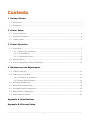
Operators Manual Copyright Information CG Triumvirate is a trademark of Agfa Corporation. CG Times based upon Times New Roman under license from the Monotype Corporation. Windows is a registered trademark of the Microsoft Corporation. All other brand and product names are trademarks, service marks, registered trademarks, or registered service marks of their respective companies. Limitation of Liability In no event shall Datamax-O’Neil be liable to the purchaser for any indirect, special or consequential damages or lost profits arising out of or relating to Datamax-O’Neil’s products, or the performance or a breach thereof, even if Datamax-O’Neil has been advised of the possibility thereof. Datamax-O’Neil’s liability, if any, to the purchaser or to the customer of the purchaser hereunder shall in no event exceed the total amounts paid to Datamax-O’Neil hereunder by the purchaser for a defective product. In no event shall Datamax-O’Neil be liable to the purchaser for any damages resulting from or related to any failure or delay of Datamax-O’Neil in the delivery or installation of the computer hardware, supplies or software or in the performance of any services. Some states do not permit the exclusion of incidental or consequential damages, and in those states the foregoing limitations may not apply. The warranties here give you specific legal rights, and you may have other legal rights which vary from state to state. Firmware (Software) Agreement The enclosed Firmware (Software) resident in the Printer is owned by Licensor or its suppliers and is licensed for used only on a single printer in the user’s Trade or Business. The User agrees not to, and not to authorize or permit any other person or party to, duplicate or copy the Firmware or the information contained in the non-volatile or programmable memory. The firmware (Software) is protected by applicable copyright laws and Licensor retains all rights not expressly granted. In no event will Licensor or its suppliers be liable for any damages or loss, including direct, incidental, economic, special, or consequential damages, arising out of the use or inability to use the Firmware (Software). Information in this document is subject to change without notice and does not represent a commitment on the part of Datamax-O’Neil Corporation. No part of this manual may be reproduced or transmitted in any form or by any means, for any purpose other than the purchaser's personal use, without the expressed written permission of Datamax-O’Neil Corporation. All rights reserved Copyright © 2013, Datamax-O’Neil Part Number 88-2351-01, Revision D Important Safety Instructions This printer has been carefully designed to provide many years of safe, reliable performance. As with all types of electrical equipment, however, there are a few basic precautions you should take to avoid hurting yourself or damaging the equipment: • • • • • • • • • Carefully read the provided installation and operating instructions. Read and follow all warning instruction labels on the printer. Place the printer on a flat, firm, solid surface. Make sure all openings on the printer remain unblocked; never insert anything into the openings or ventilation slots. Do not place the printer near a heat source. Do not use your printer near water, or spill liquid into it. Be certain that your power source matches a listed voltage rating for the printer (if unsure, check with your dealer or local utility company). Do not place the power cord where it can be stepped on; and, if the power cord becomes damaged, immediately replace it. If service is required, use only qualified trained technicians to repair your printer. Agency Compliance and Approvals MP MP MP MP Compact4: UL60950-1; 2nd Edition Compact4 Mobile: UL60950-1; 1st Edition Compact4: CSA C22.2 No. 60950-1-07 2nd Edition Compact4 Mobile: CSA C22.2 No. 60950-1-03 1st Edition The manufacturer declares under sole responsibility that this product conforms to the following standards or other normative documents: EMC: EN 55022 (1993) Class A EN 50024 (1998) WARNING!: This is a Class A product. In a domestic environment this product may cause radio interference in which case the user may be required to take adequate measures. Contents 1 Getting Started 1.1 Introduction ............................................................................................................ 1 1.2 Unpacking ............................................................................................................... 1 2 Printer Setup 2.1 Power Connection..................................................................................................... 3 2.2 Interface Connection................................................................................................. 4 2.3 Loading Labels ......................................................................................................... 5 3 Printer Operation 3.1 Front Panel.............................................................................................................. 7 3.1.1 Status Light Conditions ................................................................................... 7 3.1.2 Control Button ............................................................................................... 7 3.1.3 Configuration Label ........................................................................................ 8 3.2 Windows Driver........................................................................................................ 9 3.3 Printer Configuration Utility (DMXConfig) ................................................................... 11 4 Maintenance and Adjustments 4.1 Cleaning Intervals .................................................................................................. 13 4.2 Cleaning the Printhead ............................................................................................ 14 4.2.1 Cleaning Film Procedure ................................................................................ 14 4.2.2 Cotton Swab Procedure ................................................................................. 15 4.3 Printhead Replacement ........................................................................................... 16 4.4 Platen Roller Replacement ....................................................................................... 18 4.5 Printhead Pressure Adjustment................................................................................. 20 4.6 Media Sensor Configuration ..................................................................................... 21 4.7 Downloading Firmware............................................................................................ 22 Appendix A: Specifications Appendix B: Ethernet Setup i ii 1 Getting Started 1 1..1 1 IIn nttrro od du uccttiio on n Congratulations on your MP Compact4 Mark II printer purchase. The MP Compact4 Mark II printer family, hereafter referred to as ‘the printer’, blends the rugged durability of die-cast construction with state-of-the-art electronics and user-friendly features to redefine the standard in industrial thermal printers. The printer’s USB, RS232 serial, or optional wired and wireless LAN connectivity allows easy interfacing to any host system. This manual provides all the information necessary to operate the printer. To print labels or tags, simply refer to the instructions included with the software you have chosen to create the labels. A Windows printer driver can be found on our website (http://www.datamaxoneil.com) or on the included CD-ROM for printing from common applications. If you wish to write a custom program, a copy of the Class Series 2 Programmer’s Manual can also be found on the CD-ROM. 1 1..2 2 U Un np pa acck kiin ng g After removing the printer from the packaging material, check the contents. The following items should be included: Printer Power Cord Serial Cable (p/n 502542) Cleaning Card (p/n 70-2087-01) CD-ROM and Documentation Any special or additionally purchased items Additional Requirements: The following items are necessary for generating labels from your printer. Contact your customer support or sales representative for advice on which media and software may best be suited for your application. USB Cable Ethernet cable for optional LAN connectivity Applicable Label Media It is a good idea to save all packaging materials in the event that shipping the printer is ever required. 1 2 2 Printer Setup 2 2..1 1 P Po ow we err C Co on nn ne eccttiio on n Power Connections Before connecting Power or interface cables to the printer, ensure the Power On/Off Switch is in the ‘Off’ position. Place the printer on a firm, level surface. Ensure that the Power Switch on the Printer is in the ‘Off’ position. AC Model Connect the AC Power Cord to the receptacle on the back of the Printer, and then plug the AC Power Cord into a properly grounded outlet. (The printer’s power supply automatically detects and then adjusts to the applied line voltage; see Appendix A for the acceptable voltage ranges.) DC Model (24VDC to 48VDC) Connect the Black wire to the negative (-) pole of the battery or chassis ground. Connect both red wires to the positive (+) pole of the battery. Connect the white input connecter to the rear of the printer as shown. (The printer’s power supply automatically detects and then adjusts to the applied voltage; see Appendix A for the acceptable voltage ranges.) 3 2 2..2 2 IIn ntte errffa acce eC Co on nn ne eccttiio on n The printer can be connected to the host via the USB, serial, wired Ethernet, or optional wireless. The printer will automatically connect to the first port that delivers valid data. Once established, the printer’s power must be cycled ‘Off’ and ‘On’ to change an interface connection. LAN (RJ45 wired Ethernet) USB Wireless antenna connector (optional) COM 1 (RJ45) Before connecting Power or interface cables to the printer, ensure the Power On/Off Switch is in the ‘Off’ position. Serial Connections (COM1) The serial interface supports RS-232C communications via a RJ45 connector. The following list of serial port settings is menu selectable (via host software/driver) and must match the host computer’s serial port settings: > Baud Rate (Default 9600 bps) > Word Length (Default 8 bits). Serial to Parallel Converter An optional serial to parallel converter cable (part# 540707) is available for applications that require a parallel connection to the host. USB Connection (USB) The USB Interface is supported in Windows 95 and greater. Depending upon the operating system of your host computer, installation may differ slightly. Wired and Optional Wireless For setup information on wired and optional wireless connections, see Appendix B. 4 2 2..3 3 LLo oa ad diin ng g LLa ab be ellss Load media into the printer as follows: 1. Rotate the Printhead Latch clockwise to the unlocked position. AC Models 2. Printhead Latch DC Models Remove the Media Hub Guide: AC Models: Move the Thumb-Latch to the released position and then slide the Media Hub Guide off the Media Hub. Media Hub Guide Thumb-Latch Media Hub DC Models: Loosen the Media Guide Handle and slide the Media Hub Guide off the Media Hub. 5 Media Hub Guide Media Guide Handle Media Hub 3. Unravel approximately 12” of labels from the Label Roll. Slide the labels and Label Roll into the printer from the side as shown. 4. Label Roll Reinstall the Media Hub Guide onto the Media Hub. Be sure the Media Hub Guide is lightly touching the edge of the Label Roll. Secure the Media Hub Guide: AC Models: Move the Thumb-Latch to the locked position DC Models: Tighten the Media Guide Handle, do not over-tighten. AC Models Media Hub Guide Printhead Latch Media Hub Label Roll Thumb-Latch Media Guide Handle DC Models 5. Rotate the Printhead Latch counter-clockwise to the locked position. AC Models DC Models 6. Turn the printer ON and wait for it to enter an idle state (green light on). Press the front Control Button a couple of times to position the media and ensure proper tracking. If the printer does not correctly sense the top of each label, it may be necessary to calibrate the printer (see Section 4.6 Media Sensor Configuration). 6 3 Printer Operation 3 3..1 1 F Frro on ntt P Pa an ne ell The printer is equipped with a single multi-function Control Button and tri-color Status Light. 3.1.1 Control Button Status Light Conditions (Green) (Yellow) (Red) (Red Flashing) 3.1.2 Status Light Ready to print. Label Taken Sensor option is blocked Out of stock\labels or printer jam. Clear the printer jam or reload labels as necessary; press the Control Button to clear. Internal printer temperature is too hot, printer has entered a “cool down” mode. Control Button Printer Status Button Action Momentary Press Hold for 5 seconds until orange flashing Hold for 10 seconds – until green flashing Hold for 15 seconds – until red flashing Ready Led – Green Busy/Printing Led – Green Flashing Paused Led – Orange Faulted Led – Red Feeds Label Pauses Printer Resumes Printing Clears Faults Prints Network Report Cancels Batch Performs Quick Media Calibration Resets Parameters to Dealer Settings Resetting the printer will clear RAM of downloaded images, fonts, label formats, and remove temporary printer configuration changes. Hold for 20 seconds – until orange flashing Resets Parameters to Factory Defaults Hold for 25 seconds – Resets the Printer 7 3.1.3 Configuration Label Initiation of this mode causes the printer to print its Configuration Label and to begin the Hex Dump Mode. The Configuration Label provides valuable printer information including the firmware version, memory allocations, enabled options, communications settings, and label-counter data. To print the Configuration Label: 1. Be sure the printer is properly loaded with media (at least 4 inches wide), and that the power to the printer is off. 2. Turn on the printer. 3. When the Status Light turns on, press and hold the Control Button until printing begins. After the printer has completed printing the Configuration Label the printer will enter Hex Dump Mode. In this mode, all data sent to the printer will be immediately output in hexadecimal code, along with the printable ASCII equivalents. The Hex Dump Mode is a useful tool for advanced users in the diagnosis of problems including communications, handshaking, and label format syntax errors. To decode this information, the Programmer’s Manual is an essential reference. To exit Hex Dump Mode simply turn the printer off or perform a 'Printer Reset' by holding the Control Button for at least 25 seconds. 8 3 3..2 2 W Wiin nd do ow wss D Drriiv ve err The Windows driver is located on the Accessories CD-Rom included with your printer. For the latest version please visit our web site at www.datamax-oneil.com. Installing the Windows Driver: Place the Accessories CD-Rom included with your printer into your computers CD-Rom drive. Once the CD-Rom starts select your printer model and then select "Install Windows Driver" from the menu. When prompted, select your printer from the list, (e.g. MP Compact4 Mark II). Continue to follow the onscreen instructions to install the driver. 9 Important Notes: The Windows driver functions the same as any other Windows printer. A built in help file is available for complete information on all settings; however, there are some important settings that should be observed for trouble free printing. Page Setup Tab: Stock Options Tab: Print Speed & Printhead Temperature It is important that the Stock setting matches the size of the label you are using. If you cannot find a match for your label click 'New' and enter the dimensions of your label. These two settings will have the greatest effect on print quality. Some label stocks will require more heat and slower print speeds to generate a quality image. The Windows application software used to create the label format will likely have a "Page Setup" screen. This will also need to match the size of the label you are using. 10 3 3..3 DM 3 P MX XC Prriin Co on nffiig ntte err C g)) Co on nffiig gu urra attiio on nU Uttiilliitty y ((D DMXConfig (located on the Accessories CD-ROM) is a Windows based configuration utility that allows the user to make changes to the existing printer setup via a direct connection to the host serial port or any port with a Windows driver assigned to it. DMXConfig Features: Allows Real-Time Control/Query of Printer Configuration Define and Save Optimal Configurations for Applications Saved Configurations can be Shared with other Printers and Sent via Email Download Files, Formats and Fonts Query Memory Modules Using a port that has Windows driver assigned to it requires “Print directly to the printer” option to be set within the printer driver properties box. To change this setting: Click on the Start Icon, then click Settings > Printers and Faxes. Next, in the list of displayed printers, right click on the printer and select Properties. Then Click on the Advanced Tab and select the “Print directly to the printer” radio button and then click “OK”. Be sure to use the DMXConfig utility located on the Accessories CD-Rom that is included with your printer. Older versions might not operate correctly with some printers. For the latest version please visit our web site at www.datamax-oneil.com. 11 Once you have installed the DMXConfig utility: 1. Connect the host to the printer (see Section 2.2 Interface Connection) 2. Turn the printer ‘ON’. 3. Launch the DMXConfig utility. 4. Select the desired printer from the list (or the COM1 for serial connections). Query the printer by using the ‘Query Printer’ toolbar button (top-left). This will connect to the printer and get the current printer settings. 5. At this point you may browse the tabs and make any changes necessary to the printer configuration. Once complete, send the new settings to the printer using the ‘Configure Printer’ toolbar button. 12 Maintenance and Adjustments 4 4 4..1 1 C Clle ea an niin ng g IIn ntte errv va allss This section details the cleaning, adjusting, and troubleshooting tips for the printer. The following table outlines the recommended maintenance schedule for the various printer parts. Area Method Interval Printhead Turn off the printer before cleaning the printhead. Use solvent* on a cotton swab to clean the printhead from end to end. After every roll of media. Platen Roller Turn the power off. Rotate the platen roller and clean it thoroughly with solvent* and a cotton swab. After every roll of media. Media Path Solvent* After every roll of media. Peel/Tear Bar Solvent* As needed Media Sensor Air blow Monthly Exterior Mild detergent or desktop cleaner. As needed Interior Brush or vacuum cleaner As needed. * It is recommended that a solvent containing isopropyl alcohol be used. Isopropyl alcohol is a flammable solvent; always take the proper precautions when using this substance. Proper cleaning is critical. To maintain peak performance of the printer, Datamax-O’Neil offers a complete line of cleaning products including pens, cards, films and swabs. Visit our website at www.datamax-oneil.com to learn more. 13 4 4..2 2 C Clle ea an niin ng g tth he eP Prriin ntth he ea ad d If print quality declines (symptoms include non-compliant bar codes, print dropouts, and streaks; see sample label below), the typical cause is debris build-up on the printhead. Furthermore, when the build-up is not removed it may lead to element failure, greatly reducing the service life of the printhead. A faulty print quality label (shown). Streaks indicate a dirty or faulty printhead. 4.2.1 Cleaning Film Procedure To clean the printhead: 1. Turn the Printhead Latch to the unlocked “RELEASE” position. Remove any media installed in the printer. 2. Load the Cleaning Film in the same manner as the media, (see section 2.3). 3. Turn the Printhead Latch to locked “PRINT” position. 4. Press the Control Button several times until the Cleaning Film is fed out of the printer. 14 Printhead Latch Cleaning Film Control Button 4.2.2 Cotton Swab Procedure To clean the printhead: 1. Turn ‘Off’ and unplug the printer. Unlock the printhead latch and remove any media installed in the printer. 2. Lower the Front Panel. Allow the printhead to cool before proceeding. 3. Using a Pen or similar tool press in on the Top Cover Release and raise the Top Cover. Front Panel Pen or similar tool Top Cover Release Top Cover 4. Using a Cotton Swab moistened, not soaked, with isopropyl alcohol gently wipe away any build-up on the Printhead surface, paying close attention to the burn line. Allow the Printhead to dry. Cotton Swab Printhead (cables removed for clarity) 5. Close the Top Cover, push down until it latches closed. Raise the Front Panel and replace the media, return the Printhead Latch back to the locked position. 6. Plug in and turn ‘On’ the printer. Feed several labels to normalize tracking. 15 4 4..3 3 P Prriin ntth he ea ad dR Re ep plla acce em me en ntt To replace a damaged or worn printhead, follow the procedure below. Printheads are fragile; use extreme care when handling and never use a sharp object on the surface. If you have questions, contact a qualified technician or Datamax-O’Neil Technical Support before proceeding. To Remove: 1. Turn ‘Off’ and unplug the printer. Unlock the printhead latch and remove any media installed in the printer. 2. Lower the Front Panel. Allow the printhead to cool before proceeding. 3. Using a Pen or similar tool press in on the Top Cover Release and raise the Top Cover. Front Panel Pen or similar tool Top Cover Release Top Cover 4. While pressing down on the Printhead Carrier, loosen and remove the Printhead Screw using a Phillips Screwdriver. 16 Printhead Printhead Carrier Printhead Screw Phillips Screwdriver 5. Disconnect the Printhead Cable from the rear of the Printhead. Printhead Printhead Cable To Install: 1. Connect the Printhead Cable to the rear of the Printhead. 2. Position the Printhead into the Printhead Carrier. Be sure the two Screw Heads on the Printhead are located into the Holes of the Printhead Carrier 3. While pressing down on the Printhead Carrier, install and tighten the Printhead Screw using a Phillips Screwdriver. Printhead Printhead Carrier Printhead Screw Phillips Screwdriver Screw Heads / Holes 4. It is now recommended to clean the Printhead to remove any oil or dirt from handling. Perform the Printhead Cleaning procedure, (see section 4.2). 17 4 4..4 4 P Plla atte en nR Ro olllle err R Re ep plla acce em me en ntt To replace a damaged or platen roller, follow the procedure below. To Remove: 1. Turn ‘Off’ and unplug the printer. Unlock the printhead latch and remove any media installed in the printer. 2. Lower the Front Panel. 3. Using a Pen or similar tool press in on the Top Cover Release and raise the Top Cover. Front Panel Pen or similar tool Top Cover Release Top Cover 4. Insert your finger through the Access Hole and push out the Platen Roller Cover. 18 Platen Roller Cover Access Hole 5. Lift the Platen Roller Assembly up and out of the printer Platen Roller Assembly To Install: 1. Insert the new Platen Roller Assembly into position. Be sure the Belt is routed properly around the Gear, this can be viewed through the Access Hole. Platen Roller Assembly Belt Gear 2. Re-install the Platen Roller Cover. 3. Close the Top Cover, push down until it latches closed. Raise the Front Panel and replace the media, return the Printhead Latch back to the locked position. 4. Plug in and turn ‘On’ the printer. Feed several labels to normalize tracking. 19 4 4..5 5 P Prriin ntth he ea ad dP Prre essssu urre eA Ad djju ussttm me en ntt To accommodate a variety of media types, printhead pressure is adjustable. This pressure is factory set to work with most media types, so this adjustment should only be performed after attempting to improve print quality through increasing the printer’s “Heat” setting or decreasing the “Print Speed” setting. When adjusting, use only the minimum pressure necessary for better imaging. To adjust: 1. Lower the Front Panel. 2. Load at least 4” (102mm) wide media, see Section 2.3. 3. Print a test label from the host. Choose a label format with content that spans the width of the label. 4. Unlatch the printhead. Turn the Pressure Adjustment Screws counter-clockwise to increase the applied pressure or clockwise to decrease it. Make equal adjustments to each screw to achieve even print contrast across the media. 5. Pressure Adjustment Screws Re-latch the printhead and repeat the test print. Repeat step 4 until an acceptable print has been achieved. When using narrow media it is necessary to reduce the pressure on the outer (right) Pressure Adjustment Screw and increase the pressure on the inner (left) Pressure Adjustment Screw. This will prevent damage to the exposed areas of the printhead and platen roller. Excessive pressure can reduce the service life of the printhead and platen roller, while unequal pressure may cause faded print and label tracking problems. 20 4 4..6 6 M Me ed diia aS Se en nsso orr C Co on nffiig gu urra attiio on n To accommodate a variety of media types the printer is equipped with three sensors. A dual position transmissive sensor (for gap and notch type label media) and a reflective sensor (for “black mark” type label media). Several media types and their proper sensor settings are shown below: Media Type Gap Label Media Notch (Edge) Media Notch Media Reflective (Black Mark) Media Sensor Setting Gap (Inner or Outer) Gap (Inner) Gap (Outer) BlackMark Continuous Media Continuous* *Requires the “Label Length” value to be set. Most applications that use Gap Label Media will use the default setting of “Gap Inner”. However if “black mark” or custom notch media is being used this setting must be changed. The Media Sensor setting can be changed using the DMXConfig utility, see section 3.3 for more information. The Media Sensor settings can also be configured using the printer’s internal web pages via a LAN connection. Simply enter the IP of the printer in your browser to access these pages. 21 4 4..7 7 D Do ow wn nllo oa ad diin ng gF Fiirrm mw wa arre e The operating firmware for the printer is stored in Flash memory on the Main PCB. When firmware is updated and/or new features are added, they can be downloaded to the printer as follows: 1. Identify the new version for your model of printer from our website at www.datamax-oneil.com and download it onto your computer’s hard drive. 2. Be sure the Windows driver is installed (see Section 3.2) and the printer is connected to the host via a USB or LAN (wired or wireless) connection. The Printer Configuration Utility, (DMXConfig) may also be used to send this file to the printer. 3. Open the 'Properties' dialogue box for the printer to be updated. 4. Click on the 'Tools' tab. 5. Click on the 'Action' drop-down box and select 'Send File to Printer' 6. Change the 'Files of type:' drop-down box to 'All Files (*.*)' 7. Navigate to the location of the firmware file downloaded in Step 1, (.zg file) and click 'Open'. 8. As the new firmware is sent to the printer the Status Light will flash as the data is received. 9. Following a successful download, the printer will perform a ‘cold reset.’ The previous printer setup will not be affected unless substantial firmware data structure changes have occurred. Print a Database Configuration Label to verify your new firmware version. Following an unsuccessful download, the printer will perform a ‘warm reset’. The original firmware will remain operational. If the printer fails to reset, toggle the power Off and On. Try re-sending the file to the printer. If the failure continues, check the following possible causes An invalid or corrupted file is being downloaded - Ensure the file being downloaded is correct and applicable for your printer model. Possible communications error - Check the cable connection between the host and printer and ensure that a quality, shielded cable is used. Possible memory problem - Call for service. 22 23 A Specifications Mechanical Width 9.1” (230mm) Depth 10.2” (260mm) Height 4.1” (105mm); Compact4 4.9” (125mm); Compact4 Mobile Weight 7.7 lbs (3.5kg); Compact4 9.9 lbs (4.5kg); Compact4 Mobile Operating Temperature 41 F to 104 F (5 C to 40 C) Humidity 10% AC Input Voltage 90 - 264VAC, 47-63Hz; Compact4 24 - 48VDC; Compact4 Mobile 95% non-condensing Printing Print Method Direct Thermal Print Speed 2 – 4.9 IPS (50 – 125mm/s) Resolution 200 or 300 dpi (8 or 12 dots/mm) Tear Bar Tear Up DRAM Memory 8MB FLASH Memory 4MB Media/Ribbon Media Types Roll-Fed, Die-Cut, Continuous, Fan-Fold Media Width Range 1.58” – 4.5" (40 – 115mm) Max. Print Width 4.1” (115mm) Print Length Minimum .39" (10mm) Media Thickness Range 0.0023 – 0.0071" (58 – 180μm) Media Supply Roll Capacity 3.9" (100mm) O.D. on a 1.5" - 3.0" (40 – 77mm) core; Compact4 3.9" (100mm) O.D. on a 1.5" (40mm) core; Compact4 Mobile Communications Interface USB, RS-232 (RJ-45), and 10/100BaseT LAN interface Baud Speed 300 to 115,000 bits per second (BPS) Handshaking Xon/Xoff, CTS, DTR Parity Even, Odd, or None Stop Bits 1 or 2 Data Bits 7 or 8 Embedded Fonts and Barcodes The printer is equipped with the most popular industry fonts and bar codes; see the Class Series 2 Programmer’s Manual for full listings and detailed information. A-1 Approved Media To achieve optimum print quality and maximum printhead life, Datamax-O’Neil specifies the use of Datamax-O’Neil brand media. These supplies are specially formulated for use in our printers; use of nonDatamax-O’Neil supplies may affect the print quality, performance, and life of the printer or its components. For a current list of approved media and ribbons for use in direct thermal and thermal transfer applications, please contact a Media Representative at (407) 523-5650. S i d e Vie w Top View G F I H J D E A B Designator A B C D E F G H I J [1] [2] Media Dimensions Description label width liner width gap (or notch) between labels[2] label length[2] media thickness notch opening width Short Sensor Long Sensor distance from the media’s edge to the media sensor aperture (left justified) reflective (black) mark width[1] distance between reflective marks[2] reflective mark length[2] C Maximum [1] 4.5” (115mm) 4.5 (115mm) .12 (3mm) – .0071 (180μm) – – .08 (2mm) Minimum[1] 1.58 (40mm) 1.58 (40mm) .067 (1.7mm) .39 (10mm) .0023 (58μm) .20 (5mm) .90 (23mm) .067 (1.7mm) 4.5 (115mm) – .12 (3mm) 1.58 (40mm) .39 (10mm) .067 (1.7mm) The reflective (black) mark must be carbon based, placed on the backside of the stock, and the reflectance shall be less than 10% at wavelengths of 950 and 640 nm. The maximum allowable length of the combined label and gap (or mark) measurement cannot exceed 99.99 inches. A-2 B Ethernet Setup Introduction Before connecting Power or interface cables to the printer, ensure the Power On/Off Switch is in the ‘Off’ position. The Print Server makes IP requests at power-up, so before making a network connection to the printer consider how your IP addressing needs to be assigned. The IP addressing of the Internal Ethernet Print Server can be configured in one of two ways: Using a static IP Address or Using IP Discovery (DHCP, BootP, or RARP). At factory default settings, DHCP is enabled and (if equipped) the Wireless module is disabled. With Printer Off, connect the network cable and serial cable, then turn ON Printer. The printer will now search for a DHCP server. Allow up to 90 seconds for the printer to retrieve an IP address. If the printer does not receive a response from a DHCP sever it will fallback to a default IP: 192.168.10.26. Wired Ethernet Connection (LAN) DMXConfig (located on the Accessories CD-ROM) is a Windows based configuration utility that allows the user to make changes to the existing printer setup via a direct connection to the host computers serial connection. This is a vital tool for the use and configuration of wired and wireless printer setup, for installation and setup information see Section 3.3. 1. Connect the host to the printer with the supplied serial cable. 2. Launch the DMXConfig utility. Select the COM1 Port in the port listings. Query the printer by using the Query Printer toolbar button (top-left). This will connect to the printer and get the current printer settings. B-1 3. Next select the Network Tab. Click on the Network Report Button. This report will display the printers current IP address as well as other current network settings. If the IP address shown is valid for you network. Then this IP can be used for the windows driver setup. If the IP address shown is not valid for your network then a static IP address will need to be assigned. For static IP setup only 1. Click on the Wired Ethernet Configuration button 2. Set DHCP to Disabled, then set the following with appropriate values for your network: Printer IP Address Printer Subnet Mask Printer Gateway 3. Send the settings to the printer using the Configure Printer toolbar button. 4. The printer will reset and will connect to your network using the IP you provided. Once the previous steps have been successfully completed you may now use the IP Address to install a printer driver, and start printing from your Windows applications; see Section 3.2. B-2 Wireless Connection (optional) DMXConfig (located on the Accessories CD-ROM) is a Windows based configuration utility that allows the user to make changes to the existing printer setup via a direct connection to the host computers serial connection. This is a vital tool for the use and configuration of wired and wireless printer setup, for installation and setup information see Section 3.3. Connecting the Antenna: > Extend the antenna then align the base to the connector located on the rear of the printer. Turn the base clockwise until fully seated and tight on the connector. > Raise and position the antenna. To avoid permanent damage, do not pull on the antenna when handling the printer. 1. Connect the host to the printer with the supplied serial cable. 2. Launch the DMXConfig utility. Select the COM1 Port in the port listings. Query the printer by using the Query Printer toolbar button (top-left). This will connect to the printer and get the current printer settings. 3. Next select the Network Tab. 4. Click on the MPCrfNet Button. Locate and set the following items: > Set Wireless Type drop down box to Infrastructure. > Set the SSID field to match the SSID of your access point. > Set any WLAN Security Settings if necessary. For static IP setup: > For the DCHP setting, check the “Disabled” value. You can then set values for the printer IP, subnet mask, and gateway. 5. Click on the Generic Network Configuration button. Locate and set the following items: > Set the Network Interface drop down box to Wireless Ethernet (802.11). 6. Send the settings to the printer using the Configure Printer toolbar button. The printer will reset and will connect to your network. 7. To confirm your settings, select the Network Tab. Click on the Network Report Button. This report will display the printers current IP address as well as other current network settings Once the previous steps have been successfully completed you may now use the IP Address to install a printer driver, and start printing from your Windows applications; see Section 3.2. B-3 Printers Internal Web Pages 1. Open your web browser. Type in the IP Address of the printer. The Default IP is: 192.168.10.26. Note: If you have assigned a different IP Address to the printer, make sure to enter the correct IP Address. 2. The following page will appear: The printer’s fourteen internal web pages are accessible via the navigation bar on the left-hand side. These pages contain many items associated with printer configuration, the setup of the network card, as well as wireless security settings. You must provide a password to change any settings; the default password is sysadm After changes are sent to the printer (on all web pages), the printer must be reset in order for the changes to take effect. This can be done from the Reset Network Parameters web page. If any address parameters were changed such as IP address, subnet or gateway, the printer might not be viewable from the current host if they are no longer on the same subnet. B-4