1
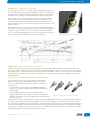
White Paper // UHPLC Connection Challenges
Troubleshooting UHPLC
Connection Challenges
As UHPLC has gained a solid foothold in the market, some of the problems that have
plagued chromatographers – like band broadening, split peaks, carryover, etc. – are
beginning to occur with greater frequency in UHPLC. While there may be numerous
causes contributing to these problems, one common issue is often overlooked:
a possible problem with the system’s tubing connections.
Problem #1 – Tubing Slippage
Because system pressures in UHPLC can exceed 15,000 psi (1,034 bar), the physical demands
on the tubing connections can be very significant. Due to the higher pressures of UHPLC
coupled with the pressure cycling that can occur in certain areas of the system (e.g., at the
injection valve), one of the biggest problems UHPLC users can face is tubing slippage.
In the areas of the system where the highest amount of pressure is experienced, the
conically-shaped fittings work to hold the tubing against the bottom of the receiving
ports in each connection. However, at the same time, the fluid in the system’s flow path
fights against the holding power of the fittings and works to drive the tubing away
from the bottom of the receiving port. Of course, any movement of the tubing away
from the bottom of the receiving port can result in dead volume, which can lead to the
chromatographic problems highlighted above.
Unfortunately, this can be very difficult to detect because the movement of the tubing
often occurs slowly. It’s possible for there to be no sign of problems with the flow
path connections (e.g., no evidence of leaking, no loss of pressure, etc), while the
chromatographic results continue to deteriorate due to the increasingly larger dead
volume chamber being formed in the receiving port.
Diagram 1 – Tubing Slippage
Application Note: Dead Volume
In a standard 10-32 coned receiving port designed for 1/16” OD tubing, for every .001” the tubing slips past the tip of the
ferrule, more than 50 nanoliters of dead volume is created.
Problem #2 – Tubing ID Compression
Because system pressures are so high – and because traditional polymer
fittings can lead to tubing slippage at UHPLC pressures as described above –
chromatographers typically use all-metal fittings in UHPLC applications to ensure
the most reliable connections.
However, some of the most popular all-metal fittings require a high-torque load to
ensure they swage properly on the tubing wall. When the need for a high-tightening
torque is coupled with the axiom that says “you can never tighten too much,” the stage
is set to significantly compress the ID of the flow path tubing, as seen in Diagram 2.
Diagram 2 – ID Compression, Competing Product
Compression similar to that shown in Diagram 2 can result in several problems:
ff
Higher system back pressures.
ff
A “throttling effect” on the fluid, resulting in increased turbulence and excessive mixing between the sample and mobile phase.
ff
Increased probability of tubing clogs due to suspended particulate matter.
Similar to the problem with tubing slippage, tubing ID compression is also difficult to detect. There are no leaks present and no loss of
pressure, making this problem tough to troubleshoot and often resulting in unnecessary system down time and repair expenditures.
1
Copyright © IDEX Health & Science LLC
I
www.idex-hs.com
UHPLC Connection Challenges // White Paper
Problem #3 – Receiving Port Damage
The high torque required to successfully swage an all-metal fitting system on
the flow path tubing doesn’t just result in tubing ID compression. Depending
upon the amount of tightening torque applied, it’s possible for material to be
ripped from the receiving port and transferred to the surface of the ferrule.
When galling occurs, the receiving port is damaged – possibly beyond use.
In severe cases, the material that is ripped from the receiving port serves
as a type of “glue” that forces the ferrule to stick in the receiving port. This
makes it difficult to remove the fitting from the port and often results in a very
expensive repair.
Even if galling doesn’t occur, it’s very typical for all-metal fittings to slightly
damage the conical surface inside the receiving port. As seen in Diagram 4, it’s
possible for a ferrule to indent the conical surface by as much as 150 µ-inch.
The more often all-metal fitting systems are used in standard receiving ports,
the more likely permanent damage of some sort will take place.
Diagram 3 – Galling, Competing Product
Diagram 4 – Profilometer Scan, Competing Product
Problem #4 – Injury From Failed Connections
Because of the tremendous pressures being applied to the fluid pathway in UHPLC applications, failed connections can
lead to injury. When a fitting system fails, if the fluid is energized to 15,000 psi or greater, it is possible for the “jet” of fluid
that rapidly exits the connection to damage soft tissue, like skin or the surface of the eye. As such, regardless of the fittings
being used, IDEX Health & Science strongly recommends the use of proper protective gear when handling connections in
UHPLC applications.
Overcoming Connection Problems with VHP Fittings
One very effective way to overcome the problems encountered in
UHPLC connections is to switch to IDEX Health & Science’s new
“VHP” line of fittings. There are three fitting families with unique
characteristics:
ff
The VHP-200 series is the highest rated at 30,000 psi (2,000 bar)
and serves as a “drop-in” replacement for stainless steel two-piece
ferrule systems.
ff
The VHP-300 and VHP-320 series offer the added benefit of
reusability, allowing the same fitting to be used to connect tubing in
different receiving ports over and over again without needing to replace
the fitting each time.
Diagram 5 – VHP-200, VHP-300, VHP-320 & VHP-325
Through the use of a front ferrule manufactured from a proprietary PEEK-polymer blend, the VHP-300 and VHP-320 fittings
ensure a biocompatible and inert fluidic seal without the risk of galling or damage occurring to the conical surface inside
the receiving ports. Additionally, the internal ferrule – featuring patent-pending technology – helps hold the tubing in place
securely without swaging onto the tubing. This feature allows these fittings to either connect the same tubing into multiple
ports (e.g., when columns are changed on a system) or connect different tubes into the same port (e.g., when reducing the
flow path tubing ID to account for lowering the system flow rate).
www.idex-hs.com
I
Copyright © IDEX Health & Science LLC
2
White Paper // UHPLC Connection Challenges
Please Note: Proper use of these fittings is paramount to obtaining optimal
performance. Details on the proper use – including recommended tightening torque and
number of times each fitting can be reused – are found on the product Spec Sheets, which are
available upon request. While each fitting in the VHP fitting family has different features and
benefits, all of the fittings share the following traits:
1. They prevent tubing slippage through the use of an innovative
ferrule design
The IDEX Health and Science engineering team developed a measurement
system to monitor tubing movement down to .0001” (2.5µm) as the fitting
systems were stressed by a variety of conditions. The external stresses
included the following: pressure dwell testing (monitoring pressure drop
over an extended period of time), and pressure shock testing (repeated
pressure cycling from ambient to above the stated pressure limit). The results
showed that the VHP fittings did not move while competitive fittings showed
movement before reaching their stated pressure limit.
Diagram 6 – VHP-320 Showing the Internal
Compression Ferrule
2. They minimize tubing ID compression and help to ensure
smoother flow
The VHP-200 fitting requires the most amount of tightening torque, yet it
does not restrict the inner diameter of the tubing, as seen in Diagram 7.
Additionally, even though the VHP-300 and VHP-320 fittings employ the
use of a stainless steel “back ferrule”, the slotted design of this ferrule
leaves a uniform fluid passage through the inner diameter of the tubing,
even after multiple tightening cycles.
Diagram 7 – Uniform Tubing Inner
Diameter after Using the VHP-200
3. They reduce, or avoid completely, any damage to internal receiving ports
The strength of a connection relies partially on the quality of the receiving port. While competitive products can leave a
damaging impression on the receiving port, as great as 150 µ-inch (as shown in Diagram 4, page 2), the VHP-200 fittings create
less than half of the impression on the receiving port, as seen in Diagram 8.
Additionally, because the VHP-300 and VHP-320 fittings use a polymer ferrule for the forward sealing function, these fittings will
not create any measurable impression on a stainless steel receiving port surface. This helps to increase the number of cycles a
quality connection can be made into a receiving port.
Diagram 8: Profilometer Scan VHP-200
Conclusion
While the challenges linked to UHPLC connections can be significant, it’s important to remember that most can be traced back to the
tubing connections. Therefore, before investing a small fortune in the replacement of expensive system components, take a little time
to inspect the tubing connections and replace or update them to fittings from IDEX Health & Science’s VHP product line. Doing so will
be much less expensive and will typically result in less system down time while ensuring improved overall system performance.
3
Copyright © IDEX Health & Science LLC
I
www.idex-hs.com