1
Register now!!
This product is eligible for
the P2HD 5 Year Warranty
Repair Program.
For details, see page 5.
http://panasonic.biz/sav/pass_e/
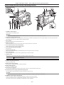
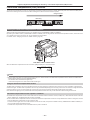
Operating Instructions
Memory Card Camera-Recorder
Model No.
AJ-PX5000G
Before operating this product, please read the instructions carefully and save this manual for future use.
M0913HM1103 -YI
ENGLISH
VQT5E21A-1(E)
Read this first!
Read this first!
indicates safety information.
WARNING:
CAUTION:
• To reduce the risk of fire, do not expose this
equipment to rain or moisture.
• To reduce the risk of fire, keep this equipment
away from all liquids. Use and store only in
locations which are not exposed to the risk of
dripping or splashing liquids, and do not place
any liquid containers on top of the equipment.
In order to maintain adequate ventilation, do not
install or place this unit in a bookcase, built-in
cabinet or any other confined space. To prevent
risk of fire hazard due to overheating, ensure that
curtains and any other materials do not obstruct
the ventilation.
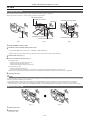
CAUTION:
Do not lift the unit by its handle while the tripod is
attached. When the tripod is attached, its weight
will also affect the unit’s handle, possibly causing
the handle to break and hurting the user. To carry
the unit while the tripod is attached, take hold of
the tripod.
WARNING:
Always keep memory cards (optional accessory)
out of the reach of babies and small children.
CAUTION:
Do not remove panel covers by unscrewing them.
No user serviceable parts inside. Refer servicing
to qualified service personnel.
CAUTION:
Excessive sound pressure from earphones and
headphones can cause hearing loss.
CAUTION:
CAUTION:
To reduce the risk of fire and annoying interference,
use the recommended accessories only.
Do not leave the unit in direct contact with the skin
for long periods of time when in use.
Low temperature burn injuries may be suffered if
the high temperature parts of this unit are in direct
contact with the skin for long periods of time.
When using the equipment for long periods of
time, make use of the tripod.
CAUTION:
To reduce the risk of fire, refer mounting of the
optional interface boards to qualified service
personnel.
CAUTION:
CAUTION:
Do not jar, swing, or shake the unit by its handle
while the conversion lens or another accessory is
attached.
Due to the added weight of the conversion lens,
any strong jolt to the handle may damage the unit
or result in personal injury.
A coin type battery is installed inside of the unit.
Do not store the unit in temperatures over 60 °C
(140 °F).
Do not leave the unit in an automobile exposed to
direct sunlight for a long period of time with doors
and windows closed.
– 2 –
Read this first!
indicates safety information.
FCC NOTICE (USA)
Declaration of Conformity
Model Number:
AJ-PX5000G
Trade Name:
Panasonic
Responsible Party:Panasonic Corporation of North America
Two Riverfront Plaza, Newark, NJ 07102
Support contact:
1-800-524-1448
This device complies with Part 15 of the FCC Rules.
Operation is subject to the following two conditions:
(1) This device may not cause harmful interference, and (2) this device must accept any interference
received, including interference that may cause undesired operation.
To assure continued compliance, follow the attached installation instructions and do not make any
unauthorized modifications.
CAUTION:
This equipment has been tested and found to comply with the limits for a Class B digital device, pursuant
to Part 15 of the FCC Rules. These limits are designed to provide reasonable protection against harmful
interference in a residential installation. This equipment generates, uses and can radiate radio frequency
energy and, if not installed and used in accordance with the instructions, may cause harmful interference
to radio communications. However, there is no guarantee that interference will not occur in a particular
installation. If this equipment does cause harmful interference to radio or television reception, which
can be determined by turning the equipment off and on, the user is encouraged to try to correct the
interference by one of the following measures:
• Reorient or relocate the receiving antenna.
• Increase the separation between the equipment and receiver.
• Connect the equipment into an outlet on a circuit different from that to which the receiver is connected.
• Consult the dealer or an experienced radio/TV technician for help.
The user may find the booklet “Something About Interference”
available from FCC local regional offices helpful.
FCC Warning:
To assure continued FCC emission limit compliance, follow the attached installation instructions and the
user must use only shielded interface cables when connecting to host computer or peripheral devices.
Also, any unauthorized changes or modifications to this equipment could void the user’s authority to
operate this device.
NOTIFICATION (Canada)
CAN ICES-3(B)/NMB-3(B)
A rechargeable battery that is recyclable powers the product you have purchased.
– 3 –
Read this first!
Declaration of Conformity
with the requirements of Technical Regulation on the Restriction Of the use of certain Hazardous Substances
in Electrical and Electronic Equipment
(adopted by Order №1057 of Cabinet of Ministers of Ukraine)
The Product is in conformity with the requirements of Technical Regulation on the Restriction Of the use of certain Hazardous Substances
in electrical and electronic equipment (TR on RoHS).
The content of hazardous substance with the exemption of the applications listed in the Annex №2 of TR on RoHS:
1. Lead (Pb) – not over 0,1 % or 1000wt ppm;
2. Cadmium (Cd) – not over 0,01 % or 100wt ppm;
3. Mercury (Hg) – not over 0,1 % or 1000wt ppm;
4. Hexavalent chromium (Cr6+) – not over 0,1 % or 1000wt ppm;
5. Polybrominated biphenyls (PBBs) – not over 0,1 % or 1000wt ppm;
6. Polybrominated diphenyl ethers (PBDEs) – not over 0,1 % or 1000wt ppm.
Декларація про Відповідність
Вимогам Технічного Регламенту Обмеження Використання деяких Небезпечних Речовин в
електричному та електронному обладнанні
(затвердженого Постановою №1057 Кабінету Міністрів України)
Виріб відповідає вимогам Технічного Регламенту Обмеження Використання деяких Небезпечних Речовин в електричному та
електронному обладнанні (ТР ОВНР).
Вміст небезпечних речовин у випадках, не обумовлених в Додатку №2 ТР ОВНР, :
1.свинець(Pb) – не перевищує 0,1 % ваги речовини або в концентрації до 1000 частин на мільйон;
2.кадмій (Cd) – не перевищує 0,01 % ваги речовини або в концентрації до 100 частин на мільйон;
3.ртуть(Hg) – не перевищує 0,1 % ваги речовини або в концентрації до 1000 частин на мільйон;
4.шестивалентний хром (Cr6+) – не перевищує 0,1 % ваги речовини або в концентрації до 1000 частин на мільйон;
5.полібромбіфеноли (PBB) – не перевищує 0,1 % ваги речовини або в концентрації до 1000 частин на мільйон;
6.полібромдефенілові ефіри (PBDE) – не перевищує 0,1 % ваги речовини або в концентрації до 1000 частин на мільйон.
Декларация о Соответствии
Требованиям Технического Регламента об Ограничении Использования некоторых Вредных
Веществ в электрическом и электронном оборудовании
(утверждённого Постановлением №1057 Кабинета Министров Украины)
Изделие соответствует требованиям Технического Регламента об Ограничении Использования некоторых Вредных Веществ в
электрическом и электронном оборудовании (ТР ОИВВ).
Содержание вредных веществ в случаях, не предусмотренных Дополнением №2 ТР ОИВВ:
1.свинец (Pb) – не превышает 0,1 % веса вещества или в концентрации до 1000 миллионных частей;
2.кадмий (Cd) – не превышает 0,01 % веса вещества или в концентрации до 100 миллионных частей;
3.ртуть (Hg) – не превышает 0,1 % веса вещества или в концентрации до 1000 миллионных частей;
4.шестивалентный хром (Cr6+) – не превышает 0,1 % веса вещества или в концентрации до 1000 миллионных частей;
5.полибромбифенолы (PBB) – не превышает 0,1 % веса вещества или в концентрации до 1000 миллионных частей;
6.полибромдифеноловые эфиры (PBDE) – не превышает 0,1 % веса вещества или в концентрации до 1000 миллионных частей.
– 4 –
Read this first!
EEE Yönetmeliğine Uygundur.
EEE Complies with Directive of Turkey.
This equipment is in compliance with the essential requirements and other relevant provisions of
Directive 1999/5/EC.
Customers can download a copy of the original DoC for this product from our DoC server:
http://www.ptc.panasonic.de/
Manufactured by: Panasonic Corporation, Osaka, Japan
Importer’s name and address of pursuant to EU rules:
Panasonic Testing Centre
Panasonic Marketing Europe GmbH
Winsbergring 15, 22525 Hamburg, Germany
EU
TO REMOVE BATTERY
Main Power Battery (Ni-Cd / Ni-MH / Li-ion Battery)
• To detach the battery, please proceed in the reverse order of the installation method described in this manual.
• If a battery made by any other manufacturer is to be used, check the Operating Instructions accompanying the battery.
Back-up Battery (Lithium Battery)
• For the removal of the battery for disposal at the end of its service life, please consult your dealer.
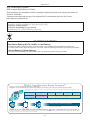
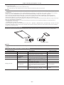
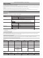
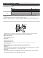
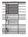
P2HD 5 Year Warranty Repair Program*1
Thank you for purchasing this Panasonic P2HD device.
Register as a user for this device to receive a special service warranty up to five years of free warranty repairs.
Customers who register as users on the website will receive an extended warranty repair valid for up to
five years.
1st year
P2HD device*2
2nd year
Basic warranty*3
3rd year
4th year
5th year*5
Extended warranty repair*4
*1: Please note that this extended warranty is not available in some countries/regions. *2: Not all models eligible for extended
warranty coverage. *3: The basic warranty period may vary depending on the country/region. *4: Not all repair work is covered by
this extended warranty. *5: The maximum warranty period may be adjusted depending on the number of hours the device has been
used.
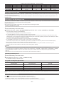
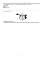
Free 5 years of Warranty Repairs
Purchase
P2 product
Register online
within 1 month
“Registration Notice”
e-mail sent
Details about user registration and the extended warranty:
Make sure to save the “Registration Notice” e-mail
during the warranty period.
http://panasonic.biz/sav/pass_e
Please note, this is a site that is not maintained by Panasonic Canada Inc. The Panasonic Canada Inc. privacy policy does not apply and is not applicable in relation to any
information submitted. This link is provided to you for convenience.
– 5 –
Programme de réparations sous garantie
pendant 5 ans pour un P2HD*1
Nous vous remercions d’avoir choisi cet appareil Panasonic P2HD.
ffSDXC logo is a trademark of SD-3C, LLC.
ffHDMI, HDMI logo, and High-Definition Multimedia Interface are trademarks or registered trademarks of HDMI Licensing LLC in the United States and/
or other countries.
ffMMC (Multi Media Card) is a registered trademark of Infineon Technologies AG.
ffMicrosoft and Windows are trademarks or registered trademarks of Microsoft Corporation in the United States and/or other countries.
ffScreenshots are used according to Microsoft Corporation guidelines.
ffApple, Macintosh, Mac OS, and QuickTime are trademarks or registered trademarks of Apple Inc. in the United States and/or other countries.
ffUniSlot logo is a registered trademark of Ikegami Tsushinki CO., LTD.
ffAll other names, company names, product names, etc., contained in this instruction manual are trademarks or registered trademarks of their
respective owners.
ffThis product is licensed under the AVC Patent Portfolio License. All other acts are not licensed except private use for personal and non-profit purposes
such as what are described below.
-- To record video in compliance with the AVC standard (AVC Video)
-- To play back AVC Video that was recorded by a consumer engaged in a personal and non-commercial activity
-- To play back AVC Video that was obtained from a video provider licensed to provide the video
Visit the MPEG LA, LLC website (http://www.mpegla.com/) for details.
ffUse of DCF Technologies under license from Multi-Format, Inc.
How to read this document
rr Illustrations
ffIllustrations of the camera, menu screens, and other items, may vary from the actual items.
rr Conventions used in this manual
ffWords and phrases in [ ] brackets indicate details and content displayed in the viewfinder or LCD monitor.
ffWords and phrases in < > brackets indicate design text used on this camera, such as button names.
rr Reference pages
ffReference pages in this document are indicated by (page 00).
rr Terminology
ffSD memory card, SDHC memory card, and SDXC memory card are referred to as SD memory card.
ffMemory card that has the “P2” logo (such as optional AJ‑P2E064FG) is referred to as “P2 memory card”.
ffMemory card that has the “microP2” logo (such as optional AJ‑P2M032AGN) is referred to as “microP2 memory card”.
ffP2 memory card and microP2 memory card are referred to only as “P2 card” unless distinguished otherwise.
ffMedia such as external hard disk drives (HDD) connected to USB are referred to as “storage devices”.
ffVideo that is created during a single recording operation is referred to as a “clip”.
– 6 –
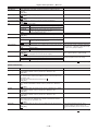
Contents
Contents
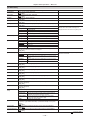
Recording and output of time codes and user bits 62
Read this first! 2
User bits settings 63
How to input user bits 63
Setting the time code 64
Before using the camera 10
Externally locking the time code 65
Setting the camera ID 67
Setting the region of use (setting frame frequency, etc.) 11
CTL counter setting and display 68
Accessories 12
Chapter 1
Overview
9
Viewfinder status display 70
Use of the camera on a system 13
Lamp display in the viewfinder 70
Basic configuration devices 13
Configuration of status display on viewfinder screen 70
Expanded configuration devices 13
Selecting display items on viewfinder screen 71
Accessories 13
Screen display 71
Checking and displaying shooting status 76
Chapter 2 Description of Parts
14
Mode check display 77
Power supply and accessory mounting section 15
Display modes and setting changes/adjustment result
messages 79
Audio (input) function section 17
Setting the marker display 79
Audio (output) function section 19
Display of marker confirmation screen (marker select function) 80
Shooting and recording/playback functions section 20
Confirmation of return video signal in the viewfinder 80
Menu operation section and thumbnail operation section 24
Zebra patterns display 80
Time code section 25
Focus assist function 80
Warning and status display section 26
Waveform monitor function 81
Description on display window 27
Adjusting and setting the LCD monitor 82
Chapter 3
Recording and Playback
29
Locking the video signal to the external reference signal 82
Adjusting and setting the viewfinder 83
Available viewfinders 83
Setting the date/time of the internal clock 30
Handling setting data 85
P2 card 31
Setting data file configuration 85
Inserting a P2 card 31
Handling SD memory cards 85
Removing a P2 card 31
Performing operations on SD memory cards 86
Preventing accidental erasure 32
How to use user data 88
P2 card access LEDs and status of P2 cards 32
How to use scene file data 88
P2 card recording time 33
How to restore menu setting status to factory setting values 89
CPS (Content Protection System) 33
Lens file 89
How to handle data recorded on P2 cards 34
Writing and reading lens files to and from SD memory card 91
Basic procedures 35
For shooting 36
Chapter 5 Preparation
Standard recording 37
93
Special recording functions 38
Power supply 94
Pre-recording 38
Mounting and setting battery 94
Loop recording 38
Using external DC power supply 95
Hot swap recording 39
Mounting and adjusting the lens 97
Recording check function 39
Mounting the lens 97
Shot mark recording function 39
Flange back adjustment 97
Text memo recording function 40
White shading compensation 98
Proxy recording 41
Chromatic aberration compensation function (CAC) 99
Proxy settings 41
Preparing for audio input 102
Recording the proxy data 42
Using the front microphone 102
Recording to the SD memory card 42
Using a wireless microphone receiver 102
Checking the proxy data 42
Using audio devices 103
Error displays about proxy data recordings 43
Mounting accessories 104
Normal and variable speed playback 45
Mounting the camera on a tripod 104
Chapter 4
Adjustments and Settings for
Recording
46
Attaching the shoulder strap 104
Attaching the rain cover 105
Connecting the <DC OUT> terminal with the external
recording start/stop switch 106
Multi formats 47
Selecting recording signals 47
Chapter 6 Thumbnail Operations for Clips
107
System modes and recording functions 47
List of recording settings and recording functions 47
Thumbnail operations 108
Selecting video output 48
Thumbnail operation overview 108
List of recording/playback and output formats 48
Thumbnail screen 108
Adjusting the white and black balance 49
Selecting thumbnails 110
Adjusting the white balance 49
Thumbnail screen display settings 111
Adjusting the black balance 51
Playing back clips 112
Changing thumbnails 112
Setting the electronic shutter 53
Shot mark 113
Shutter mode 53
Text memo 113
Setting the shutter mode and speed 53
Deleting clips 115
Setting the synchro scan mode 54
Restoring clips 115
Flash band compensation (FBC) function 55
Reconnecting incomplete clips 115
Setting the flash band compensation function 55
Copying clips 115
Assigning functions to <USER> buttons 56
Setting clip metadata 116
Selecting audio input and adjusting recording levels 58
Formatting a P2 card 118
Selecting audio input signals 58
Formatting
SD
memory
cards 118
Adjusting the recording levels 58
Properties 119
Selection of external reference signal and generator lock
Connecting to external devices using the <USB3.0> terminal
setting 61
(host) (USB storage mode) 123
Locking the video signal to the external reference signal 61
Setting the time data 62
– 7 –
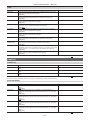
Contents
Chapter 7
Menu Operations
130
Setting menu structure 131
Menu types and how to open them 131
Main menu structure 131
[OPTION MENU] structure 133
Setting menu display 134
Setting menu basic operations 134
Setting [USER MENU] 135
Menu list 136
[PAINT] 136
[VF] 143
[CAMERA] 147
[CLIP] 152
[REC/PB] 154
[I/F SETUP] 157
[FILE] 164
[MAINTENANCE] 166
[SYSTEM] 168
[USER MENU SEL] 169
[OPTION MENU] 169
Setting items to [USER MENU] and loading/reading the
settings to a data file 170
Chapter 8
Connecting to External Devices
183
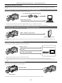
Linking to External Devices 184
Connecting the external device to the <USB2.0> terminal
(device) 184
Connecting the external device to the <USB3.0> terminal
(host) 184
Connecting the video and monitor 184
Recording images of external devices 184
Connection function via <USB2.0> or <USB3.0> terminals 185
Connecting to a computer in the USB device mode 185
USB storage mode 186
Connecting to the remote control unit (AJ‑RC10G) 187
Connecting to the extension control unit (AG‑EC4G) 188
Chapter 9
Maintenance and Inspection
189
Inspections before shooting 190
Preparing to inspect 190
Inspecting the camera unit 190
Inspecting the memory recording functions 190
Maintenance 193
Charging the built-in battery 193
Warning system 194
Warnings description list 194
Error code 196
Warning information display 196
Warning/error displays in the thumbnail operation, menu
operation, and USB storage mode 197
Updating the camera firmware 199
Chapter 10 Specification
200
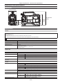
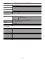
Dimensions and specifications 201
Dimensions 201
201
Specifications Details of the connector signals 204
Index 207
– 8 –
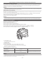
Chapter 1
Overview
Before using the camera, read this chapter, and check the accessories.
Chapter 1 Overview — Before using the camera
Before using the camera
rr Caution regarding laser beams
The MOS sensor may be damaged if the MOS sensor is subjected to light from a laser beam.
Take sufficient care to prevent laser beams from striking the lens when shooting in an environment where laser devices are used.
rr Note the following points.
ffWhen preparing to record important images, always shoot some advance test footage to verify that both pictures and sound are being recorded
normally.
ffShould video or audio recording fail due to a malfunction of the camera or the P2 cards used, we will not assume liability for such failure.
rr What to remember when throwing memory cards away or transferring them to others
Formatting memory cards or deleting data using the functions of the camera or a computer will merely change the file management information: it will
not completely erase the data on the cards. When throwing these cards away or transferring them to others, either physically destroy them or use a
data deletion program for computers (commercially available) to completely erase the data. Users are responsible for managing the data stored in their
memory cards.
rr Software information about this product
1 This product includes software licensed under GNU General Public License (GPL) and GNU Lesser General Public License (LGPL), and
customers are hereby notified that they have rights to obtain, re-engineer and redistribute the source code of these software.
2 This product includes software licensed under MIT-License.
3 This product includes software developed by the OpenSSL Project for use in the OpenSSL Toolkit (http://www.openssl.org/).
4 This product includes software licensed under OpenBSD License.
5 This product includes PHP, freely available from <http://www.php.net/>.
6 This software is based in part on the work of the Independent JPEG Group.
Details are contained on the CD provided with the camera. Refer to the “LDOC” folder. (These details are originally provided in English.)
For details on how to obtain the source code, visit the following website.
http://pro-av.panasonic.net/
We do not accept inquiries about the details of the source code obtained by the customer.
rr Precautions when installing USB drivers
For the latest information on the driver, visit the following website.
http://pro-av.panasonic.net/
ffInstall the required driver into your computer from the website.
ffFor installation procedure of the driver, refer to the installation manual on the website.
– 10 –
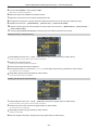
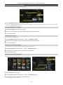
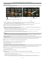
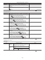
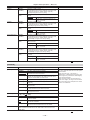
Chapter 1 Overview — Setting the region of use (setting frame frequency, etc.)
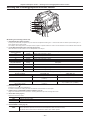
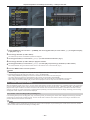
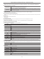
Setting the region of use (setting frame frequency, etc.)
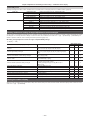
When the camera is shipped, the region of use is not set. Before you use the camera, follow the steps below to change the setting to the frame
frequency of the region of use.
1After connecting the power supply to the camera and turning the camera on, press the <MENU> button while holding down the
<LIGHT> button.
[OPTION MENU] is displayed.
2Use the jog dial button (or cursor buttons) to select [AREA SELECT], and select the region to be used from among [NTSC]/[NTSC
(J)]/[PAL].
3Press the jog dial button (or <SET> button).
The camera restarts automatically, and the initial data for each region is reflected in the initialization values and the setting values currently in use.
4Select [YES] in the confirmation message, and press the jog dial button (or <SET> button).
@@NOTE
tt To apply settings, select [NTSC]/[NTSC (J)]/[PAL] by [AREA SELECT], and then be sure to press the <SET> button.
tt When [AREA SELECT] is changed, [AREA SET] flashes.
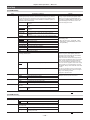
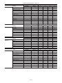
tt When making this setting to use the camera for the first time, only the following items are changed on the camera. Menu setting values other the
following items stay at their factory settings.
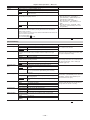
[LINE&FREQ]
Factory settings
[NTSC]
[NTSC (J)]
[PAL]
[1080‑59.94i]
[1080‑59.94i]
[1080‑59.94i]
[1080‑50i]
[OFF]
[SETUP(7.5%)]
[ON]
[ON]
[OFF]
[REAR LINE IN LVL]
[4dB]
[4dB]
[4dB]
[0dB]
[AUDIO OUT LVL]
[4dB]
[4dB]
[4dB]
[0dB]
[HEADROOM]
[20dB]
[20dB]
[20dB]
[18dB]
GUI metadata language
display
US English
US English
Japanese/for Japan
US English
[LANGUAGE]*
No display
No display
[ENGLISH]
[JAPANESE]
No display
* For details, refer to “Setting metadata display language” (page 118).
– 11 –
Chapter 1 Overview — Accessories
Accessories
Shoulder strap (page 104)
Mount cap (already attached to the product) (page 15)
CD-ROM
ffOperating Instructions
ffUtility software
For installation procedures, refer to the installation manual on the CD-ROM.
@@NOTE
tt After unpacking the product, dispose of the packing material properly.
– 12 –
Chapter 1 Overview — Use of the camera on a system
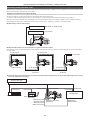
Use of the camera on a system
Parts other than the camera are optionally available. Use the following recommended parts.
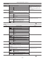
Basic configuration devices
Lenses, batteries, etc. are needed for shooting with the camera.
Part name
Part No.
Remark
Electronic HD view finder
AJ‑HVF21KG
“Adjusting and setting the viewfinder” (page 83)
Electronic HD color view finder
AG‑CVF10G/AG‑CVF15G
“Adjusting and setting the viewfinder” (page 83)
Super-directional electret stereo microphone
(phantom +48V)
AJ‑MC900G
“Using the front microphone” (page 102)
Lens (Bayonet type)
FUJINON/CANON
“Mounting and adjusting the lens” (page 97)
Battery
HYTRON140*1
DIONIC HC/90*1
V-mount type battery plate
ffENDURA E‑10
“Mounting and setting battery” (page 94)
SD memory card*2
P2 memory card*2
microP2 memory card*2
Visit the support desk at the website*2.
“P2 card” (page 31)
*1 A battery holder is provided as standard on the main unit.
*2 For the latest information on P2 cards and SD memory cards that are not described in the Operating Instructions, visit the support desk at the following
website:
http://pro-av.panasonic.net/
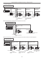
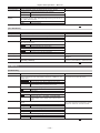
Expanded configuration devices
The following devices are also available in addition to the basic configuration devices.
Part name
Remote control cable
Part No.
AJ‑C10050G
Remark
—
Remote control unit
AJ‑RC10G
“Connecting to the remote control unit
(AJ‑RC10G)” (page 187)
Extension control unit
AG‑EC4G
“Connecting to the extension control unit
(AG‑EC4G)” (page 188)
LCD monitor
BT‑LH80W/BT‑LH900, etc.
Storage device
—
UniSlot wireless microphone receiver
—
External DC power supply
—
—
—
—
“Using external DC power supply” (page 95)
Accessories
Part name
Part No.
Remark
Soft carrying case
AJ‑SC900
Hard carrying case
AJ‑HT901G
—
Rain cover
SHAN-RC700
“Attaching the rain cover” (page 105)
Tripod adaptor
SHAN-TM700
“Mounting the camera on a tripod” (page 104)
—
– 13 –
Chapter 2
Description of Parts
This chapter describes the names, functions, and operations of parts on the camera. Details displayed on the display window are also described.
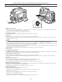
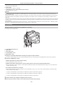
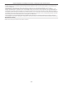
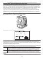
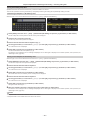
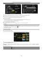
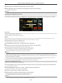
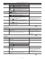
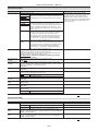
Chapter 2 Description of Parts — Power supply and accessory mounting section
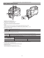
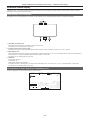
Power supply and accessory mounting section
16
10
19
17
18 10
9
19
20
21
2
3
11
12
22
4
5
6 7
8
1
13 14
15
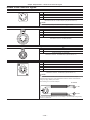
1 <POWER> switch (page 35)
Switch used to turn on/off the power.
@@NOTE
tt Even when the <POWER> switch is set to the <OFF> position, the camera is not shut off from the main power.
2 Viewfinder left/right positioning ring
To adjust the left/right position of the viewfinder, loosen this ring, and slide the viewfinder to the left or right to adjust it to an easy-to-view position.
After adjustment, turn in the <LOCK> direction and firmly clamp.
3 <VF> terminal
Mount the viewfinder AJ‑HVF21KG (optional), etc.
4 Mount cap (page 97)
Raise the lens lever to remove the cap. Replace the cap when the lens is not mounted.
5 Lens cable/microphone cable clamp (page 97)
Used for securing the lens and microphone cables.
6 Lens mount (2/3-type bayonet) (page 97)
Mount the lens.
7 Tripod mount (page 104)
Attach the optional tripod adaptor (SHAN-TM700) when mounting the camera on the tripod.
8 Lens lever (page 97)
After mounting the lens to the lens mount, tighten the lever to secure the lens.
9 <LIGHT> switch
Select how to turn on/off the video light connected to the light output terminal.
<AUTO>
<MANUAL>
When the video light is left turned on, the light is illuminated at the same time that recording starts on the camera and goes out at the
same time that recording stops.
The light is illuminated according to whether the video light is turned on/off.
10 Shoulder strap fittings (page 104)
Attach the shoulder strap.
11 Battery release lever (page 94)
Pull this battery release lever down to release the battery.
12 Battery holder (page 94)
Mount the Anton/Bauer battery.
13 <DC IN> terminal (page 95)
This is the input terminal for the external power supply. Connect to the external DC power supply.
14 <DC OUT> (DC power supply) output terminal (page 106)
This is the DC12 V output terminal. It provides a maximum current of 1.5 A.
@@NOTE
tt Make sure that polarity is correct before connecting an external device. Doing so may result in a malfunction.
15 <REMOTE> terminal (page 188) (page 187)
Connect the remote control unit AJ‑RC10G (optional) to remote-control some functions.
Connect the extension control unit AG‑EC4G (optional) to remote-control some functions.
The remote control function is scheduled to be supported in future upgrades.
– 15 –
Chapter 2 Description of Parts — Power supply and accessory mounting section
16 Cable holders
Used for clamping the light and microphone cables in place.
17 Accessory mounting holes
Attach accessories. Do not use for purposes other than attaching accessories.
ffMounting hole size
-- 1/4‑20 UNC (screw length 10 mm or shorter)
-- 3/8‑16 UNC (screw length 10 mm or shorter)
18 Light shoe
Attach the video light.
ffMounting hole size
1/4‑20 UNC (screw length 6 mm or shorter)
19 Viewfinder front/back position clamp lever
To adjust the front/back position of the viewfinder, loosen this lever, and slide the viewfinder to the left or right to adjust it to an easy-to-view position.
After adjustment, turn in the <LOCK> direction and firmly clamp.
20 Light output terminal
Connect the Ultralight 2 of Anton/Bauer (optional) or an equivalent video light of 50 W or under.
The battery charge level drops sharply when the light is illuminated. When using the light, using a battery of 90 Wh or more is recommended.
21 Microphone holder mounting screws
Screws for mounting the microphone holder AJ‑MH800G (optional) or VF interface box AG‑YA500G (optional).
22 <LENS> terminal (page 97)
Connect the lens connection cable. For details of the lens used, refer to the Operating Instructions for the lens.
– 16 –
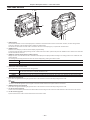
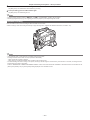
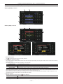
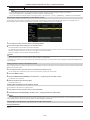
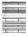
Chapter 2 Description of Parts — Audio (input) function section
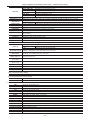
Audio (input) function section
2
5
3
4
1
6
9
7
8
1 <F.AUDIO LEVEL> (audio recording level adjustment) dial (page 59)
ffAdjust the recording level of audio channels 1/2 (or 3/4).
ffSet which of audio channels 1/2 or 3/4 is to be adjusted at the main menu → [I/F SETUP] → [MIC/AUDIO] → [VR SELECT].
ffWhen the position of the <AUDIO SELECT CH1/3>/<AUDIO SELECT CH2/4> switch is at <AUTO>, adjustment is automatic, and the <F.AUDIO
LEVEL> and <AUDIO LEVEL CH1/3>/<AUDIO LEVEL CH2/4> dials do not function.
ffSet whether to enable the <F.AUDIO LEVEL> dial at the main menu → [I/F SETUP] → [MIC/AUDIO] → [FRONT VR CH1(CH3)] or [FRONT VR
CH2(CH4)].
2 <AUDIO LEVEL CH1/3>/<AUDIO LEVEL CH2/4> (audio channel 1/3, 2/4 recording level adjustment) dial
ffWhen the <AUDIO SELECT CH1/3>/<AUDIO SELECT CH2/4> switch is set to <MANU>, the recording level of audio channels 1/2 (3/4) can be
adjusted by these dials.
ffSet which of audio channels 1/2 or 3/4 is to be adjusted at the main menu → [I/F SETUP] → [MIC/AUDIO] → [VR SELECT].
ffThese knobs have a locking mechanism, so turn the dial while pressing in when making adjustments.
3 <AUDIO IN> (audio input selector) switch
Select the input signal to be recorded to audio channel 1/2/3/4.
<FRONT>
<W.L.>
<REAR>
Records the microphone input signal connected to the <MIC IN> (microphone input) terminal.
Records the input signal from the wireless microphone receiver.
Records the audio input signal from the audio equipment connected to <AUDIO IN CH1/3> and <AUDIO IN CH2/4> (audio input
channels 1/3, 2/4) terminals.
@@NOTE
tt When the stereo microphone AJ‑MC900G (optional) is used, set both <CH1> and <CH2> (or <CH3> and <CH4>) to <FRONT>. L CH is recorded
to <CH1> (<CH3>), and R CH is recorded to <CH2> (<CH4>), respectively.
4 <AUDIO SELECT CH1/3>/<AUDIO SELECT CH2/4> (audio channel 1/3, 2/4/automatic/manual level adjustment selector) switch
Select the method to adjust the recording level for audio channel 1/2 (3/4).
<AUTO>
Adjusts automatically.
<MANU>
Adjusts manually.
ffSet which of audio channels 1/2 or 3/4 is to be adjusted at the main menu → [I/F SETUP] → [MIC/AUDIO] → [VR SELECT].
5 Wireless slot (page 102)
Mount the UniSlot wireless microphone receiver (optional).
6 <LINE>/<MIC> (line input/microphone input) selector switch (page 103)
Switch the audio input signal connected to <AUDIO IN CH1/3> and <AUDIO IN CH2/4> (audio input channels 1/3, 2/4) terminals.
<LINE>
Inputs audio signals from line-input audio equipment.
<MIC>
Inputs audio signals from the microphone.
7 Microphone input power selector switch (page 191)
Turn on/off the power supply to the microphone connected to the <AUDIO IN CH1/3> and <AUDIO IN CH2/4> (audio input channels 1/3, 2/4)
terminals.
<+48V>
Supplies +48 V power to the microphone.
<OFF>
Does not supply power to the microphone.
@@NOTE
tt When microphone input <+48V> is set and microphones are not connected to the <AUDIO IN CH1/3> and <AUDIO IN CH2/4> terminals, lowfrequency noise may occur. This is not a problem when a microphone is connected.
– 17 –
Chapter 2 Description of Parts — Audio (input) function section
tt When [ON] is not set in the main menu → [I/F SETUP] → [MIC/AUDIO] → [REAR MIC POWER], power is not supplied regardless of the switch
position.
8 <AUDIO IN CH1/3>, <AUDIO IN CH2/4> (audio input channel 1/3, 2/4) terminals (page 103)
Connect the audio equipment or the microphone.
9 <MIC IN> (microphone input) terminal (page 102)
ffConnect the microphone (optional).
ffThe phantom microphone can also be used. To use this, set [ON] in the main menu → [I/F SETUP] → [MIC/AUDIO] → [FRONT MIC POWER].
When it is set to [ON] and a microphone is not connected, low-frequency noise may occur. This is not a problem when a microphone is connected.
– 18 –
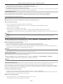
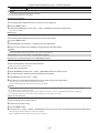
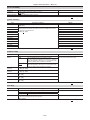
Chapter 2 Description of Parts — Audio (output) function section
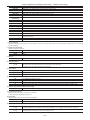
Audio (output) function section
1 2
3
5
4
6
6
7
1 <MONITOR> (volume adjustment) dial
Adjust the volume of the speaker and earphones.
2 <ALRAM> (alarm volume adjustment) dial
Adjust the volume of the alarm from the speaker and earphones.
When set to the minimum position, the alarm cannot be heard.
3 Speaker
During recording, EE audio can be monitored, and during playback, playback audio can be monitored.
The alarm is output in sync with flashing/lighting of the <WARNING> lamp or warning indicator.
Audio from the speaker automatically disappears when earphones are connected to the <PHONES> terminal.
4 Audio channel selector switch
Switch the audio channels output to the speaker, earphones, and <AUDIO OUT> terminal.
<CH1/2>
Outputs the signals of audio channels 1 and 2.
<CH3/4>
Outputs the signals of audio channels 3 and 4.
The channel display of the audio level meter on the display window and viewfinder are also switched interlocked to operation of this switch.
5 <MONITOR SELECT> (audio selection) selector switch
Select audio output from the speaker, earphones and <AUDIO OUT> terminal interlocked with the audio channel selector switch.
<CH1/3>
<ST>
<CH2/4>
Outputs the signal of either audio channel 1 or audio channel 3.
Outputs either the stereo audio signals of audio channels 1 and 2 or the stereo audio signals of audio channels 3 and 4. Stereo audio
signals can be changed to the MIX signals in the main menu → [I/F SETUP] → [MIC/AUDIO] → [MONITOR SELECT].
Outputs the signal of either audio channel 2 or audio channel 4.
Audio channel selector switch
<MONITOR SELECT> (audio selection)
selector switch
<CH1/2>
<CH3/4>
<CH1/3>
Audio channel 1
Audio channel 3
<ST>
Stereo output from audio channels 1 and 2*
Stereo output from audio channels 3 and 4*
<CH2/4>
Audio channel 2
Audio channel 4
* [STEREO] or [MIX] can be switched to in the main menu → [I/F SETUP] → [MIC/AUDIO] → [MONITOR SELECT].
6 <PHONES> (earphones) terminal (mini jack)
This is the terminal for connecting the audio monitor earphones. (stereo)
Audio that is output is the same on both terminals (front side, rear side)
7 <AUDIO OUT> terminal
ffOutput audio signals recorded on audio channel 1/2 or 3/4.
ffSelect output signals by the <MONITOR SELECT> selector switch.
– 19 –
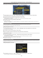
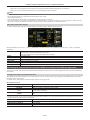
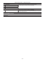
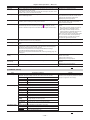
Chapter 2 Description of Parts — Shooting and recording/playback functions section
Shooting and recording/playback functions section
1
2
3
4
5
6
7 8 9 10
rr Shooting and recording (Camera unit)
1 <SYNCHRO SCAN> adjustment button
In the synchro scan mode, the speed of synchro scan can be adjusted. Pressing the <−> button slows down the shutter speed. Pressing the <+>
button speeds up the shutter speed.
For example, when taking shots of a computer monitor, adjust to a position where the noise for the horizontal bar in the viewfinder will be reduced.
2 <CC FILTER>/<ND FILTER> (filter switching) dial (page 36)
Select the filter to suit the luminance or color temperature of the subject.
Position of <CC FILTER>
dial (large diameter)
Setting
<A>
<3200 K>
Sets the color temperature to 3200 K.
<B>
<4300 K>
Sets the color temperature to 4300 K.
<C>
<5600 K>
Sets the color temperature to 5600 K.
<D>
<6300 K>
Sets the color temperature to 6300 K.
Position of <ND FILTER>
dial (small diameter)
Setting
<1>
<CLEAR>
Does not use the ND filter.
<2>
<1/4ND>
Reduces the amount of light entering the MOS sensor to 1/4.
<3>
<1/16ND>
Reduces the amount of light entering the MOS sensor to 1/16.
<4>
<1/64ND>
Reduces the amount of light entering the MOS sensor to 1/64.
Description
Description
Refer to the following table to switch the <CC FILTER> and <ND FILTER> dials according to the shooting conditions.
Shooting conditions
<CC FILTER> dial
<ND FILTER> dial
Sunset, sunrise, inside studio
<A> (<3200 K>)
<1> (<CLEAR>)
Outdoors in the clear skies
<B> (<4300 K>) or <C> (<5600 K>) or <D>
(<6300 K>)
<2> (<1/4ND>) or <3> (<1/16ND>)
Outdoors under cloudy skies or in the rain
<D> (<6300 K>)
<1> (<CLEAR>) or <2> (<1/4ND>)
Clear, bright scenery such as snowy scenery,
tall mountains, seaside
<B> (<4300 K>) or <C> (<5600 K>) or <D>
(<6300 K>)
<3> (<1/16ND>) or <4> (<1/64ND>)
3 Focal plane index < >
Indicates the focal plane of the MOS sensor.
It provides a reference for making accurate focal distance measurements from the subject.
4 <USER> buttons (<USER MAIN>/<USER1>/<USER2>) (page 56)
Assign user-selected functions to each button. Pressing each button performs the assigned function.
5 <SHUTTER> switch (page 53)
Switches the electronic shutter.
<OFF>
Disables the electronic shutter.
<ON>
Enables the electronic shutter.
<SEL>
Changes the speed of the electronic shutter.
This is a spring switch. Each turn towards the <SEL> side alters the shutter speed.
6 <AUTO W/B BAL> switch (page 49)
<AWB>
Adjusts white balance automatically. When this switch is operated with the <WHITE BAL> switch on the side set to the <A> or <B>
position, adjustment is performed in several seconds and adjustment values are stored in memory.
Note that this does not work when the <WHITE BAL> switch is at the <PRST> position.
– 20 –
Chapter 2 Description of Parts — Shooting and recording/playback functions section
<ABB>
Adjusts black balance automatically.
When [ON] is set in main menu → [CAMERA] → [SW MODE] → [SHD,ABB SW CTL], the automatic adjustment function for black
shading can be assigned to this switch.
@@NOTE
tt When white balance or black balance is automatically adjusted, each of these automatic adjustments is canceled by pushing the <ABB> side or
<AWB> side again. The adjustment values at this time return to the values before automatic adjustment was performed.
7 <MARKER SEL>/<MODE CHECK/MENU CANCEL> switch (page 80)
This is the spring switch to check selection of the marker and the shooting status of the camera.
<MKR>
<MCK/MCL>
Each time the switch is pressed towards the <MKR> side, the marker display switches in the viewfinder between [A] marker display →
[B] marker display → hidden.
When the power is turned on, the status before the power was turned off is displayed.
Each time the switch is pressed towards the <MCK/MCL> side, the six screens that indicate the setting status of the camera ([STATUS]
screen, [!LED] screen, [FUNCTION] screen, [AUDIO] screen, [CAC] screen, [USER SW] screen) are switched in order in the viewfinder.
This does not affect the output signals from the camera. The display goes out in about five seconds. The display of the current selected
screen is continued by holding down the button.
If the button is pressed towards the <MCK/MCL> side while the setting menu is displayed, this button doubles as the switch for
canceling new setting values.
8 <GAIN> switch (page 49)
ffSwitch the video amplifier gain according to the lighting conditions under which you are shooting.
ffThe gain values for the <L>/<M>/<H> positions can be set by each [[S] MASTER GAIN] of [LOW SETTING], [MID SETTING], or [HIGH SETTING]
in the main menu → [PAINT].
ffFactory settings are L = 0 dB, M = 6 dB, and H = 12 dB.
9 <OUTPUT>/<AUTO KNEE> selector switch
Select the video signals output to the memory, viewfinder and video monitor from the camera unit.
<CAM>/<ON>
Video captured on the camera is output and the auto knee function is activated.
Instead of the auto knee function, the dynamic range stretcher (DRS) function can be assigned.
<CAM>/<OFF>
Video captured with the camera is output and the auto knee function is not activated.
The knee point is fixed to the level set by the main menu → [PAINT] → [KNEE/LEVEL] → [KNEE MASTER POINT].
<BARS>/<OFF>
The color bar signal is output. The auto knee function is not activated.
The color bar signal can be selected from the four types in the main menu → [CAMERA] → [SW MODE] → [COLOR BARS].
(page 149)
@@NOTE
tt As the factory setting, when the <OUTPUT>/<AUTO KNEE> selector switch is set to <BARS>, and <CH1> on the <AUDIO IN> switch is set to
<FRONT>, test signals are output to all four audio channels. The test signal output method can be changed in the main menu → [I/F SETUP] →
[MIC/AUDIO] → [TEST TONE].
tt Auto knee function
When you adjust levels to shoot people or scenery against a strongly lit background, the background will be totally white-out, with buildings and
other objects blurred. In such a case, the auto knee function reproduces the background clearly.
The auto knee function is effective when shooting the following scenes:
- The subject is a person positioned in the shade under a clear sky.
- The subject is a person inside a car or a building, and you also want to capture the background visible through a window.
- The subject is a high-contrast scene.
10 <WHITE BAL> (white balance memory selector) switch (page 49)
Select the white balance adjustment method.
<PRST>
Set the switch to this position when you have no time to adjust the white balance.
ffThe factory setting is 3200 K.
ffYou can change to any color temperature in the main menu → [CAMERA] → [WHITE BALANCE MODE] → [COLOR TEMP PRE].
(page 150)
<A>/<B>
Adjust automatically the white balance by pressing the <AUTO W/B BAL> switch towards <AWB> and saves the adjusted value to
memory A or B.
You can also assign the auto tracking white balance (ATW) function to <B> in the main menu → [CAMERA] → [WHITE BALANCE
MODE] → [AWB B]. (page 50)
– 21 –
Chapter 2 Description of Parts — Shooting and recording/playback functions section
12 13
25
20 21 22 23
26
27
24
28
14
15
16
11
17
29 30 31 32 33
18
19
18
rr Shooting and recording/playback functions section (Recording unit)
11 <REC> button (page 37)
Recording is started by pressing this button. Recording is stopped by pressing this button again.
This button has the same function as the VTR button on the lens side.
12 <SHOT MARKER> button (page 39)
ffShot marks can be added to the thumbnail of a clip while that clip is being recorded. Thumbnails can also be selected in the LCD monitor, and shot
marks can be added by pressing this button.
ffThe selected function can be assigned as the <USER3> button. Set the function to be assigned in the main menu → [CAMERA] → [USER SW] →
[SHOT MARK (U3)].
13 <TEXT MEMO> button (page 40)
ffText memos can be recorded by pressing this button during recording/playback or while playback is paused.
ffThe selected function can be assigned as the <USER4> button. Set the function to be assigned in the main menu → [CAMERA] → [USER SW] →
[TEXT MEMO (U4)].
14 P2 memory card access LED (page 32)
Indicate the access status of recording and playback of each card.
15 P2 memory card slot
16 Busy (active status indication) lamp (page 86)
Indicate the active status of the SD memory card, and is illuminated when the card is active.
@@NOTE
tt Do not insert or remove the card while the lamp is lit. This might damage the SD memory card.
17 SD memory card slot (page 86)
This is the insertion slot for the SD memory card (optional). Use the SD memory card for recording/opening the setting menu and lens files for the
camera, or uploading metadata or proxy recording, etc.
@@NOTE
tt Cautions when using SD memory cards
- On the camera, use SD memory cards that conform to the SD standard, SDHC standard, or the SDXC standard. When performing proxy
recording, use SDHC memory cards, SDXC memory cards, or SD memory cards with the class description of class2 or higher.
- MMC (Multi Media Card) cannot be used. (Bear in mind that taking pictures may no longer be possible if you use them.)
- When using miniSD/microSD cards with the camera, always install the adaptor specially designed for miniSD/microSD cards. (The camera will
not work properly if only the miniSD/microSD adaptor is installed. Make sure that the card has been inserted into the adaptor before use.)
- Use of Panasonic SD memory cards and miniSD/microSD cards is recommended. Be sure to format cards on the camera before use.
- Refer to our support desk at the following website for the latest information not included in these operating instructions.
http://pro-av.panasonic.net/
- SDHC memory cards are a standard that was established in 2006 by the SD Association for large-capacity memory cards that exceed 2 GB.
- SDXC memory cards are a standard that was established in 2009 by the SD Association for large-capacity memory cards that exceed 32 GB.
18 microP2 memory card access LED (page 32)
Indicates the access status of recording and playback of each microP2 memory card.
19 microP2 memory card slot
– 22 –
Chapter 2 Description of Parts — Shooting and recording/playback functions section
20 <%/REW> (rewind) button
Press this button during a pause to perform fast-reverse playback.
Press it during playback to perform fast-reverse playback at approximately 4x speed.
If it is pressed with playback paused, the clip being played back is paused at its start point (cued state).
21 <STOP> (stop) button
Press this button to stop playback.
22 <FF/)> (fast forward) button
Press this button during a pause to perform fast playback.
Press it during playback to perform fast playback at approximately 4x speed.
If it is pressed with playback paused, the clip being played back is paused at the start point of the next clip (cued state).
23 <PLAY/PAUSE> (play/pause) button
Press this button to view the playback image using the viewfinder screen or the monitor screen.
Pressing it during playback pauses playback.
24 <MON OUT CHARACTER> switch (page 67)
Specifies whether characters are superimposed over the output from <SDI OUT2>, <VIDEO OUT>, and <HDMI> terminals.
<ON>
Superimposes characters.
<OFF>
Does not superimpose characters.
25 <USB2.0> terminal (sub-host)
Used in future upgrades.
26 <USB2.0> terminal (device) (page 185)
In the USB device mode, the camera can be connected to the computer by the USB 2.0 cable to transfer data. In this case, recording playback
operations and camera shooting are not possible.
27 <USB3.0> terminal (host) (page 186)
In the USB storage mode, connect external hard disk drives, etc.
@@NOTE
tt For the cable to be connected to this terminal, use the double-shielded cable.
tt When connecting to a USB 3.0 compatible storage device, use a cable compliant with the USB 3.0 standard.
28 <LAN> terminal (100BASE‑TX)
Used in future upgrades.
29 <HDMI OUT> (monitor output) terminal
This is the video output terminal for the monitor. Video can be output separately from the <SDI OUT1> terminal according to the setting of the main
menu → [I/F SETUP] → [OUTPUT SEL] → [MONITOR OUT MODE]. The down-conversion signal can be selected in [OUTPUT SEL] → [SDI2/HDMI
OUT]. Up-conversion is not supported.
Superimposing of characters can be set by the <MON OUT CHARACTER> switch independently of the <SDI OUT1> terminal. (page 67)
30 <SDI OUT1> (output) terminal
This is the output terminal exclusively for SDI. Output is performed in the same signal format as in the system mode. Down-conversion and upconversion are not supported.
Superimposing of characters can be set independently of the <HDMI OUT>, <SDI OUT2>, and <VIDEO OUT> terminals. (page 67)
31 <SDI OUT2> (monitor output) terminal
This is the video output terminal for the monitor. Video can be output separately from the <SDI OUT1> terminal according to the setting of the main
menu → [I/F SETUP] → [OUTPUT SEL] → [MONITOR OUT MODE]. HD SDI or down-converted SD SDI can be selected in [OUTPUT SEL] →
[SDI2/HDMI OUT]. Up-conversion is not supported.
Superimposing of characters can be set by the <MON OUT CHARACTER> switch independently of the <SDI OUT1> terminal. (page 67)
@@NOTE
tt As the factory setting, output of the signal from the <SDI OUT2> terminal is stopped. To enable output, set [ON] in the main menu → [I/F SETUP]
→ [OUTPUT SEL] → [SDI OUT2].
tt During HD SDI signal output, use a 5C‑FB or higher cable.
32 <SDI IN> (input) terminal
Inputs the HD/SD SDI signals. Signals from this input terminal can be recorded by setting [SDI] in the main menu → [SYSTEM] → [SYSTEM MODE]
→ [REC SIGNAL]. 3G‑HD SDI input signals can be recorded at 1080P. For details, refer to “Selecting recording signals” (page 47).
In the main menu → [I/F SETUP] → [GENLOCK] → [GENLOCK] → [SDI IN], a generator lock can also be applied referenced to this input signal.
(page 61)
@@NOTE
tt During HD SDI signal output, use a 5C‑FB or higher cable.
33 <VIDEO OUT> (monitor output) terminal
This is the video output terminal for the monitor. Video can be output separately from the <SDI OUT1> terminal according to the setting of main
menu → [I/F SETUP] → [OUTPUT SEL] → [MONITOR OUT MODE]. The VBS signal is output at all times.
Superimposing of characters can be set by the <MON OUT CHARACTER> switch independently of the <SDI OUT1> terminal. (page 67)
@@NOTE
tt As the factory setting, output of the signal from the <VIDEO OUT> terminal is stopped. To enable output, set [ON] in the main menu → [I/F SETUP]
→ [OUTPUT SEL] → [VIDEO OUT].
– 23 –
Chapter 2 Description of Parts — Menu operation section and thumbnail operation section
Menu operation section and thumbnail operation section
3
4
1
2
5
6
7
8
9
1 <MENU> button (page 134)
ffPress this button to display [USER MENU] on the viewfinder screen. Press this button for three seconds or more to display the main menu on the
viewfinder screen. Press it again to return to the original image.
ffThis button functions in the same way as the <MENU> button (cursor).
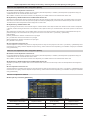
2 Jog dial button (page 134)
ffWith the setting menu open, navigate through setting menus, select items, and set values.
3 LCD monitor
Displays the video in the viewfinder. Clips on the P2 card can also be displayed as thumbnails.
During thumbnail display, clips can be operated or deleted, and P2 cards can be formatted, for example, by operating the cursor/<SET> button or
operating the main menu → [CLIP].
@@NOTE
tt The quality of the image displayed in this monitor is different from the quality of the image that is actually recorded/output to the camera. Bear this
in mind, in particular, when [480‑59.94i] or [576‑50i] is set in the main menu → [SYSTEM] → [SYSTEM MODE] → [LINE&FREQ].
tt When [480‑59.94i] or [576‑50i] is set in the main menu → [SYSTEM] → [SYSTEM MODE] → [LINE&FREQ], and camera video and playback video
are switched, the image on the monitor is temporarily disrupted. This is not a malfunction.
tt If the battery is removed or the external DC power plug is removed while the power is on, a residual image might remain in the LCD screen. This is
not a malfunction. It will disappear if the screen is left as it is.
tt At lower temperatures, residual images sometimes appear to increase on screen. This is not a malfunction.
4 <OPEN> button
This is used to open the LCD monitor.
5 <THUMBNAIL> button (page 110)
This switches the video in the LCD monitor from video in the viewfinder to thumbnail display of clips. Pressing this button again returns the display to
the original video in the viewfinder. Button operations are disabled during recording and playback.
6 <EXIT>/<CANCEL> buttons (page 110)
Restore the display to the previous state while the setting menu or property screen is displayed.
Pressing this button while holding down the <SHIFT> button acts as the cancel button. This is convenient, for example, for batch-canceling clip
selections.
7 Cursor/<SET> button (page 110)
This is used for setting time codes or user bit values, and selecting thumbnails or operating menus.
When the setting menu is displayed, it is used for selecting items or changing settings.
The four triangular buttons are the cursor buttons, and the square button in the center is the <SET> button.
8 <MENU> buttons (cursor) (page 110)
Press this button to display [USER MENU] on the viewfinder screen. Press this button for three seconds or more to display the main menu on the
viewfinder screen. Press it again to return to the original image.
This button functions in the same way as the <MENU> button on the front side.
9 <SHIFT> button (page 110)
Press this button with other buttons held down at the same time.
ff<SHIFT> button + cursor button (`/{)
This moves the cursor to the thumbnail of the clip at the start or the end on the thumbnail screen.
ff<SHIFT> button + <SET> button
This selects all clips from the previously selected clip up to the clip at the cursor position.
ff<SHIFT> button + <EXIT>/<CANCEL> button
This works as the cancelation function. (page 24)
Operations with the <SHIFT> button held down are displayed at the bottom of each button.
– 24 –
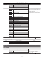
Chapter 2 Description of Parts — Time code section
Time code section
1 2 3
4
5
6
7 8
1 <HOLD> button
The time data indication on the counter display area is retained for the duration that this button is held down. However, the time code generator
continues to advance. Press the button again to release the retained state.
This function is used to learn the time code or time data of the time counter display (CTL) of a particular recorded scene.
2 <RESET> button
Resets the time data (CTL) of the time counter display to [00:00:00:00].
To return the real time data to factory settings, set the <TCG> switch to the <SET> position and press the <RESET> button. Both the time code data
and user bits data are reset to 0.
3 <DISPLAY> (counter display selector) switch (page 27)
Displays the CTL, time code and user bits in the time counter display of the display window according to the setting position of the <DISPLAY> and
<TCG> switches.
The shooting date, shooting time and time zone can also be displayed by pressing the <HOLD> button.
<UB>
Displays the users bits, shooting date, shooting time, and time zone.
<TC>
Displays the time code.
<CTL>
Displays CTL.
4 <TCG> (time code selector) switch
Sets the advance mode for the built-in time code generator.
<F‑RUN>
<SET>
<R‑RUN>
Used to advance the time code continuously, regardless of the P2 card recording operation. Set to this position to, for example, set the
time code to the current time or externally lock the time code.
Used to set the time code or user bits.
Used to advance the time code only during recording. Records continuously time codes on P2 cards that have been spliced together.
5 <SDI IN> terminal (page 65)
Input reference signals when setting the generator lock on the camera unit or when externally locking the time code.
@@NOTE
tt Be sure to set the SDI signals to input to signals of the same format selected in the system mode on the camera.
6 <GENLOCK IN> terminal (page 65)
Input reference signals when setting the generator lock on the camera unit or when externally locking the time code.
7 <TC OUT> terminal (page 65)
Connect to the time code input terminal of the external device when locking the time code of the external device to the time code on the camera.
8 <TC IN> terminal (page 65)
Input the reference time code to this terminal when the time code is locked.
– 25 –
Chapter 2 Description of Parts — Warning and status display section
Warning and status display section
1 2
5 6
3
4
7
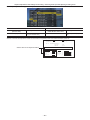
1 Display window
Displays memory-related warnings, battery charge level, audio level, and time data.
@@NOTE
tt If the camera is left with the battery attached, the various data will be displayed on the display window even if the power is turned off. To turn the
display off to save the battery from wearing down, set [OFF] in the main menu → [SYSTEM] → [SYSTEM SETUP] → [P.OFF LCD DISPLAY].
2 <LIGHT> button
Controls lighting of the display window. Each press toggles lighting of the display window on and off.
3 <WARNING> lamp (page 194)
Starts flashing or is illuminated if something unusual occurs in the memory.
4 <USB> lamp
Lights when the camera is in the USB mode.
5 Back tally switch
Controls the action of the back and rear tally lamps.
<ON>
Enables the back and rear tally lamps.
<OFF>
Disables the back and rear tally lamps.
6 Back tally lamp
When the back tally switch is set to <ON>, the lamp acts in the same way as the front tally lamp at the viewfinder.
7 Rear tally lamp
When the back tally switch is set to <ON>, the lamp acts in the same way as the back tally lamp.
– 26 –
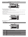
Chapter 2 Description of Parts — Description on display window
Description on display window
3
1
2
rr P2 card, battery charge level, audio level display
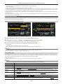
1 Media remaining space indicator bar
Indicates the remaining free space in the P2 card using a 7-segment display.
The P2 card remaining time indicated by a single segment is set in three or five minutes in the main menu → [I/F SETUP] → [BATTERY/P2CARD]
→ [CARD REMAIN/Seg]. Segments go out one segment at a time at each preset time.
2 Battery charge level indicator bar
When a battery with a digital indication (% indication) is used, all seven segments up to the [F] position light if the battery charge level is 70% or
higher.
When the battery charge level falls below 70%, the segments go out one by one for each 10% drop. When set [100%] in the main menu → [I/F
SETUP] → [BATTERY/P2CARD] → [BATT REMAIN FULL], seven segments can be set to light at 100%.
3 Audio channel level meter
When the audio channel selector switch is set to <CH1/2>, audio channel display numbers 1 and 2 are displayed, and the audio level of CH1 and
CH2 is displayed. When <CH3/4> is set, audio channel display numbers 3 and 4 are displayed, and the audio level of CH3 and CH4 is displayed.
4
5
rr Memory operation/status related display
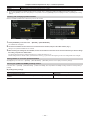
4 Error code display (page 196)
5 Information display
[LOOP]
Lights during loop recording, and flashes during recording standby. (page 38)
7
6
6 Time code indications
[NDF]
[DF]
Indicates when the time code is in the non-drop frame mode.
Indicates when the time code is in the drop frame mode.
[SLAVE]
Indicates when the time code is externally locked.
[HOLD]
Indicates when the time code generator/read value is held.
[CTL]
Lights when <CTL> is selected by the <DISPLAY> switch and the CTL count value is displayed.
[TCG]
Lights when <TC> (or <UB>) is selected by the <DISPLAY> switch and the TC (or UB) generator value is displayed.
[TC]
[VTCG]
Lights when <TC> (or <UB>) is selected by the <DISPLAY> switch and the TC (or UB) reader value is displayed.
Lights when <UB> is selected by the <DISPLAY> switch and the VIUB generator value is displayed.
[VTC]
Lights when <UB> is selected by the <DISPLAY> switch and the VIUB reader value is displayed.
[TIME]
Lights when <UB> is selected by the <DISPLAY> switch and the real time hours/minutes/seconds value is displayed.
– 27 –
Chapter 2 Description of Parts — Description on display window
[DATE]
No display (time zone)
Time counter display
Lights when <UB> is selected by the <DISPLAY> switch and the real time year/month/day value is displayed.
[VTCG], [TIME], and [DATE] go out when <UB> is selected by the <DISPLAY> switch and the real-time hours/minutes value of the
time zone is displayed.
Indicates the time code, user bits, CTL, and real time.
@@NOTE
tt When <UB> is selected by the <DISPLAY> switch, each press of the <HOLD> button repeats [VTCG] ([VTC]) → [DATE] → [TIME] → no display
(time zone) → [TCG] ([TC]).
7 Mode display
[W]
Lights during operation in the SD mode (480/59.94i, 576/50i) and in the 16:9 mode.
[HD]
Lights during operation in the HD mode.
[DV]
Lights when the recording/playback format is DV.
[P‑REC]
Lights when set [ON] in the main menu → [REC/PB] → [REC FUNCTION] → [PRE REC]. [P‑REC] flashes when recording is
continued after the tally lamp goes out.
– 28 –
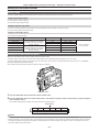
Chapter 3
Recording and Playback
This chapter describes the basic procedure for recording and playback. It also describes special shooting methods such as pre-recording and loop
recording.
Chapter 3 Recording and Playback — Setting the date/time of the internal clock
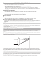
Setting the date/time of the internal clock
The value of the time is recorded to content (clips) and affects the thumbnail playback order. Before recording, be sure to check and set the date and
time zone.
1Set the <DISPLAY> switch to <UB>.
2Press the <HOLD> button several times to display the time zone (time difference from Greenwich mean time) on the display
window.
For time zone display, refer to “Time code indications” (page 27) in “Description on display window”.
3Set the <TCG> switch to <SET>.
4Set hours/minutes (h/min) and advance (no display)/delay ([−] display) from the Greenwich mean time by the cursor buttons (`/
{).
Example) Time difference 5:00 delay (New York)
Set as [05:00 −].
The time zones are always recorded as metadata together with date/time.
Set this matched to the local time by referring to the time zone table.
5Set the <TCG> switch to <F‑RUN> or <R‑RUN> to apply the time zone.
6Press the <HOLD> button several times to display [DATE] on the display window.
7Set the <TCG> switch to <SET>.
8Set date (Y/M/D) by the cursor buttons.
The year setting upper limit is 2037.
I: The digit to be set (flashing) moves to the right.
Y: The digit to be set (flashing) moves to the left.
`: The value of the flashing digit is incremented by one.
{: The value of the flashing digit is decremented by one.
9Press the <HOLD> button to display [TIME] on the display window.
10Set hours/minutes/seconds (h/min/s) by the cursor buttons.
11 Set the <TCG> switch to <F‑RUN> or <R‑RUN>.
When this switch is switched, the internal clock starts to operate.
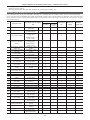
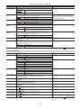
rr Time zone table
Time
difference
Region
00:00 Greenwich
−00:30
Time
difference
Region
Time
difference
Region
Time
difference
−06:30
+01:00 Central Europe
+07:30
−07:00 Denver
+01:30
+08:00 Beijing
−01:00 Azores
−07:30
+02:00 Eastern Europe
+08:30
−01:30
−08:00 Los Angeles
+02:30
+09:00 Tokyo
Region
−02:00 Mid-Atlantic
−08:30
+03:00 Moscow
+09:30 Darwin
−02:30
−09:00 Alaska
+03:30 Tehran
+10:00 Guam
+10:30 Lord Howe Island
−03:00 Buenos Aires
−09:30 Marquesas Islands
+04:00 Abu Dhabi
−03:30 Newfoundland
−10:00 Hawaii
+04:30 Kabul
+11:00 Solomon Islands
−04:00 Halifax
−10:30
+05:00 Islamabad
+11:30 Norfolk Island
−04:30
−11:00 Midway Islands
+05:30 Bombay
+12:00 New Zealand
−05:00 New York
−11:30
+06:00 Dakar
+12:45 Chatham Islands
+13:00
−05:30
−12:00 Kwajalein Atoll
+06:30 Yangon
−06:00 Chicago
+00:30
+07:00 Bangkok
@@NOTE
tt Be sure to make this setting before using the camera for the first time. After, do not change the setting during use.
tt Thumbnail operations and menu operations on thumbnail operation section are not possible while the <TCG> switch is set to <SET>.
tt After setting year/month/day in step 8, the internal clock will start if the <TCG> switch is set to <F‑RUN> or <R‑RUN>.
tt To cancel settings while setting year/month/day, hours/minutes/seconds and time zone, set the <TCG> switch to <F‑RUN> or <R‑RUN> with the
<SET> button held down.
tt Clock accuracy is a lunar inequality of approximately ±30 seconds with the power off. When accurate time is required, check and reset the time when
the power is turned on.
tt The built-in clock runs for several years on the camera’s built-in lithium cell. When the lithium cell runs low, [BACKUP BATT EMPTY] will be displayed
in the viewfinder when the camera is turned on. For details, refer to “Maintenance” (page 193).
– 30 –
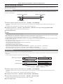
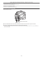
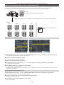
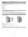
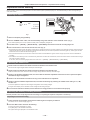
Chapter 3 Recording and Playback — P2 card
P2 card
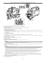
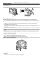
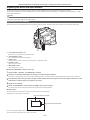
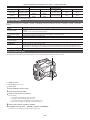
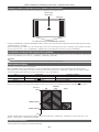
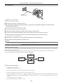
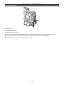
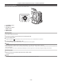
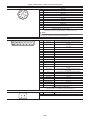
Inserting a P2 card
When using the camera for the first time, be sure to set the time data beforehand. (page 30)
Select and use either of the P2 or microP2 memory card slot on the camera.
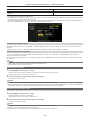
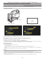
P2 memory card slot 1
P2 memory card slot 2
P2 memory card access LED
Eject button
microP2 memory card slot 3
Slot cover
microP2 memory card slot 4
Fig. 1
microP2 memory card access LED
Fig. 2
Fig. 3
1Set the <POWER> switch to <ON>.
2Set which of P2 or microP2 memory cards to use.
1) Select [REC MEDIA] in the main menu → [REC/PB] → [REC/PB SETUP].
2) When using P2 memory cards, select [P2], and when using microP2 memory cards, select [microP2].
3Open the slot cover. (Fig. 1)
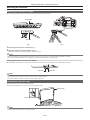
4Insert a card into the card slot. (Fig. 2)
ffP2 memory cards
- Insert the card until the eject button pops out.
- Insert the card with the logo facing up.
- Press the eject button that pops up to the right.
ffmicroP2 memory cards
- Insert with the label side facing up.
- Card in microP2 memory card slot 3 can be inserted or removed by sliding the small window on the slot cover.
ffAfter a card is inserted, the P2 card access LED for the appropriate slot indicates the status of the P2 card. (Fig. 3) (page 32)
5Close the slot cover.
@@NOTE
tt To prevent cards from falling out, dust from entering and reduce the risk of exposure to static electricity, close the slot cover before moving the camera.
tt Be sure to format P2 cards only on a P2 device.
tt The microP2 memory card with the P2 card adaptor (AJ‑P2AD1G) attached cannot be inserted into the P2 memory card slot on the camera.
tt If SDHC/SDXC memory cards other than microP2 memory cards are used on the microP2 memory card slot, operation is not guaranteed.
tt If a microP2 memory card is inserted slowly, [FORMAT ERROR!] or [NOT SUPPORTED!] may be displayed. In such a case, insert the card again.
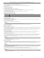
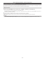
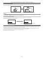
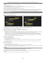
Removing a P2 card
Fig. 1
Fig. 2
1Open the slot cover.
2Remove the card.
ffP2 memory cards
– 31 –
Chapter 3 Recording and Playback — P2 card
- Lift the eject button (Fig. 1), and press in. (Fig. 2)
ffmicroP2 memory cards
- Press in the microP2 card further into the camera and let go.
- The microP2 memory card is released from the card slot, and the microP2 memory card can be removed.
@@NOTE
tt After insertion, do not remove the P2 card while it is being accessed or recognized (the P2 card access LED is flashing orange). Doing so may result
in a malfunction.
tt If the P2 card is removed while being accessed, [TURN POWER OFF] is displayed on the viewfinder screen, and the camera gives out a warning
indication by an alarm, <WARNING> lamp, etc. All P2 card access LEDs flash rapidly in orange. Turn off the power. (page 194)
tt If the P2 card is removed while being accessed, clips on it may become irregular. Check the clips and restore them, if required. (page 115)
tt If the P2 card being formatted is removed, formatting of the P2 card is not guaranteed. In this case, [TURN POWER OFF] is displayed on the
viewfinder screen displays. Turn off the power then back on again, and reformat the P2 card.
tt If a P2 card is inserted into another slot during playback, the inserted card is not recognized and the P2 card access LED does not light. The P2 card
starts to be recognized when playback ends.
tt Even if a P2 card is inserted in a vacant card slot during recording, the P2 card may not be recognized immediately in the following instance:
- Immediately after a pre-recording
- Immediately after a recording slot is switched
tt The P2 card access LED can be set to off at all times in the main menu → [REC/PB] → [REC/PB SETUP] → [ACCESS LED]. In this case, turn off the
power before removing the card, or, after the card is inserted or after operation (recording, playback, etc.) has stopped, and wait for the charging to
complete before removing the card.
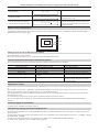
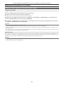
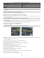
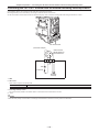
Preventing accidental erasure
To prevent the content of a P2 card from being accidentally erased, set the write-protect switch on the P2 card to the Protect (or LOCK) position.
Write-protect switch
Write-protect switch
@@NOTE
tt Write-protect switch can be switched while the card is being accessed (during recording or playback), but does not take effect until accessing of the
card stops.
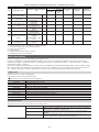
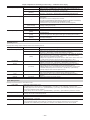
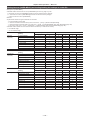
P2 card access LEDs and status of P2 cards
P2 card access LED
P2 card status
Mode check display*
Is illuminated green
Recording possible
Reading/writing are both possible.
[ACTIVE]
Is illuminated orange
Recording target
Reading/writing are both possible. The card is currently
the recording target (including loop recording).
[ACTIVE]
Flashing orange
Accessing card
Reading/writing are currently being performed.
[ACCESSING]
Flashing orange rapidly
The card is being
recognized.
The P2 card is being recognized.
[INFO READING]
Card full
There is no free space on the P2 card. Reading only is
possible.
[FULL]
Write protect
The write-protect switch on the P2 card is at the Protect
position. Reading only is possible.
[PROTECTED]
Unrecordable card
Recording is not possible by the currently set recording
format since the SD memory card, etc. is inserted. To
record the card, change the recording format or use a
P2 card.
[REC IMPOSSIBLE]
Slot that is not recording
target
The card is inserted in a slot that is different from the
slot selected in the main menu → [REC/PB] → [REC/PB
SETUP] → [REC MEDIA] ([P2] or [microP2])
No display
Flashing green slowly
– 32 –
Chapter 3 Recording and Playback — P2 card
P2 card access LED
P2 card status
Mode check display*
Card not supported
This card cannot be used on the camera. Replace the
card.
Illegal format
The P2 card is not properly formatted. Reformat the card. [FORMAT ERROR]
No card
The P2 card is not inserted. The card is waiting to be
recognized.
[NO CARD]
Unauthenticated card
This microP2 memory card cannot be authenticated.
Select the main menu → [CLIP] → [AUTHENTICATE],
and enter the password.
For details, refer to “Manual CPS authentication”
(page 122).
[AUTH NG]
USB non-access
The P2 card cannot be accessed since the mode is the
USB device mode.
No display
Off
[NOT SUPPORTED]
* The mode check is displayed on the viewfinder screen. For details, refer to “Viewfinder status display” (page 70).
P2 card recording time
rr P2 cards supported on the camera
Optional P2 and microP2 memory cards with a capacity of 4 GB to 64 GB can be used with the camera. (As of September, 2013)
@@NOTE
tt AJ‑P2C002SG (2 GB) cards cannot be used.
tt When AVC‑Intra 100 in 1080/59.94P or 1080/50P mode is selected, you cannot record to the following P2 cards.
- P2 memory cards of R, A, or E series
tt The driver installed on the camera may be required to be updated depending on the type of P2 card. (page 199)
tt Refer to our support desk at the following website for the latest information not included in these operating instructions.
http://pro-av.panasonic.net/
rr P2 card recording times
(Example when a 64 GB card is used)
System mode
Recording format (codec)
1080P
1080i
480i, 576i
Recording time
AVC‑I100
Approx. 32 min
AVC‑I100
Approx. 64 min
AVC‑G25
Approx. 256 min
DVCPRO50
Approx. 128 min
DV
Approx. 256 min
@@NOTE
tt The above table shows values for regular recording. With native recording, even longer recording times are available depending on the system mode.
tt In the case of 32 GB P2 cards, the recording time becomes 1/2 of the above recording times, in the case of 16 GB P2 cards, the recording time
becomes 1/4, and in the case of 8 GB P2 cards, the recording time becomes 1/8.
tt Indicated capacities include management and other area, so the space available for recording is less than the values in the table above.
Dividing clips recorded on P2 cards
If P2 cards with a capacity of 8 GB or more are used on the camera, recording is automatically continued as another clip when a single continuous
recording time exceeds the following times. When thumbnails for clips are handled (displayed, deleted, restored, etc.) on P2 devices, they can be
handled as a single clip. Clips may be displayed as separate clips in nonlinear editing software and on a computer. When recording on microP2 memory
cards that exceed 32 GB using AVC‑LongG codec, recording can be continued as the same clip by setting in main menu → [REC/PB] → [REC/PB
SETUP] → [FILE SPLIT].
Recording format (excluding native recording)
Continuous recording time
AVC‑I100 (1080P)
Approx. 3 min
AVC‑I100 (1080i)
DVCPRO HD
Approx. 5 min
AVC‑G50
AVC‑I50
DVCPRO50
Approx. 10 min
AVC‑G25
DVCPRO
DV
Approx. 20 min
CPS (Content Protection System)
The microP2 memory card supports the security function “Content Protection System” that allows encryption formatting to prevent data leak to third
parties.
To use the CPS function, set a CPS password to the camera, and enable the microP2 memory card authentication and encryption formatting functions.
An encrypted microP2 memory card will be automatically recognized between devices where the same CPS password is set, and recording and
playback of the microP2 memory card are enabled. For details, refer to “Setting CPS password” (page 122).
@@NOTE
tt Set or delete the CPS password in the main menu → [CLIP] → [PROPERTY] → [CPS PASSWORD].
– 33 –
Chapter 3 Recording and Playback — P2 card
tt Up to 16 characters can be input.
tt The encrypted microP2 memory card is not recognized on the SD card slot in a computer.
tt If the card is unable to be recognized, authenticate with the correct password or format and use the card as recording media. Recording data on the
card failed to be recognized cannot be checked. Do not perform any operation other than manual authentication and formatting with the failed card
inserted.
tt To access the encrypted card from a computer in USB device mode, authenticate the encrypted card with P2 Viewer Plus.
How to handle data recorded on P2 cards
P2 cards are semiconductor memory cards that are used as the recording medium in the professional video production and broadcasting devices that
make up the DVCPRO P2 series.
ffSince data recorded in the P2 format is in a file format, they have excellent compatibility with computers. The file structure is a unique format, which
in addition to video and audio data in MXF files contains various other important information items. The folder structure links data recorded in the P2
format as shown below.
Drive:\
CONTENTS
AVCLIP
AUDIO
CLIP
ICON
PROXY
VIDEO
VOICE
LASTCLIP.TXT*
All these folders are required.
If even part of this information is modified or deleted, the data may no longer be
recognized as P2 data, or the card may no longer be able to be used with P2
devices.
This is the file to which the information of the final clip that was recorded with the
P2 device is written.
@@NOTE
tt P2 cards formatted on devices other than microP2 memory card compatible devices do not have the AVCLIP folder. For P2 cards without the AVCLIP
folder, the folder will automatically be created when recording is performed on microP2 memory card compatible devices.
tt When transferring data from a P2 card to a computer, or when rewriting data saved on a computer back to a P2 card, to prevent data loss be sure to
download the special “P2 Viewer Plus” software. For details on downloading P2 Viewer Plus and the operating environment, visit the support desk at
the following website:
http://pro-av.panasonic.net/
tt When using regular IT tools such as Microsoft Windows Explorer or Apple Finder to transfer data to a computer, follow the instructions below.
However, be sure to use P2 Viewer Plus when returning data back to a P2 card.
- Transfer the corresponding CONTENTS folder and LASTCLIP.TXT file together as a set.
- Do not transfer individual files from the CONTENTS folder.
- When copying, copy the LASTCLIP.TXT file at the same time as the CONTENTS folder.
- When transferring the data in multiple P2 cards to a computer, create a folder for each P2 card to prevent clips with the same name from being
overwritten.
- Do not delete data from the P2 card.
- Be sure to format P2 cards on a P2 device or P2 Viewer Plus.
– 34 –
Chapter 3 Recording and Playback — Basic procedures
Basic procedures
This section describes the basic procedures for shooting and recording. Before you actually start shooting, pre-inspect your system to ensure that it
works properly. (page 190)
Power supply setup to P2 card insertion
Fig. 1
Fig. 2
1Insert a charged battery pack. (Fig. 1)
2Set the <POWER> switch to <ON>, and make sure that five or more levels on the battery charge level indicator bar are lit.
If five or more levels on the battery charge level indicator bar are not lit, be sure to check the battery settings. (page 163) If the settings are correct,
replace with a fully charged battery.
3Insert a P2 card, make sure that the P2 card access LED is illuminated orange or green, and then close the slot cover. (Fig. 2)
When two P2 cards are inserted in the card slots, the P2 card with the smaller slot number will be recorded to first. Note, however, that regardless of
the slot number, if a P2 card is inserted later, that P2 card will not be accessed until the previously inserted P2 card has been recorded to.
ffExample: When P2 cards are inserted in two slots
If P2 memory cards are inserted into two slots, the P2 cards are used in the order of the slot number 1 → 2 (on the microP2 memory card slot, slot
number 3 → 4). However, if the P2 card in slot number 1 (3) is removed and then re-inserted, the P2 cards will be used in the order of slot number
2 → 1 (4 → 3).
The P2 card number to be recorded to is held even if the camera is turned off. When the camera is next turned on, recording can be continued to the
same P2 as before the camera was turned off.
@@NOTE
tt If a low battery charge level is indicated even after replacing with a fully charged battery, make sure that the battery has been inserted correctly.
(page 163)
tt When set [SLOT 1/3] in the main menu → [REC/PB] → [REC/PB SETUP] → [P.ON REC SLOT SEL], the P2 card with the smaller slot number will be
recorded to first each time that camera is turned on.
tt Select which of P2 or microP2 memory card slot is to be used as the recording card slot beforehand. If the card is inserted into the slot which is not
selected as the recording slot, recording is disabled.
Select the recording slot by the following method.
- Set the main menu → [REC/PB] → [REC/PB SETUP] → [REC MEDIA].
- Press the <USER> buttons to which [REC MEDIA] is assigned to switch the selected slot.
- Re-insert the card into the selected card slot. For details, refer to “Inserting a P2 card” (page 31).
Shooting and recording switch settings
After turning on the power and inserting the P2 card, set the switches as follows before starting operations.
a b c
a: <USER MAIN> button
Set to the card slot for recording target.
b: <GAIN> switch
Normally, set this to <L> (0 dB). If it is too dark, set the gain to an appropriate value.
– 35 –
d e
Chapter 3 Recording and Playback — Basic procedures
c: <OUTPUT>/<AUTO KNEE> switch
Set this switch to <CAM>/<ON>.
d: <TCG> switch
Set this switch to <F‑RUN> or <R‑RUN>.
e: <AUDIO SELECT CH1/3>, <AUDIO SELECT CH2/4> switches
Set these switches to <AUTO>.
@@NOTE
tt The [SLOT SEL] function is assigned to the <USER MAIN> button in the factory setting. You can switch to the P2 card to be recorded from two or
more inserted P2 cards.
When the P2 to record to is switched, the number of the card slot in which the P2 card to be recorded to is inserted is displayed on the P2 remaining
card capacity indicator in the viewfinder. (For details on indications in the viewfinder, refer to “Configuration of status display on viewfinder screen”
(page 70).)
tt The [SLOT SEL] is enabled also during recording. The [SLOT SEL] indicator flashes in the viewfinder until switching of the P2 card to be recorded to is
completed. If the card could not be switched immediately after recording is started or immediately after the P2 card is switched, [SLOT SEL INVALID]
will be displayed.
tt Switch the recording media between P2 memory cards (slots 1, 2) and microP2 memory cards (slots 3, 4) from the main menu → [REC/PB] → [REC/
PB SETUP] → [REC MEDIA]. [REC MEDIA] can also be assigned to the <USER> button.
For shooting
White/black balance adjustment to completion of recording
For shooting, use the following steps.
a
b
c
d
e
a: <CC FILTER>/<ND FILTER> dial
b: <REC> button
c: <SHUTTER> switch
d: <AUTO W/B BAL> switch
e: <WHITE BAL> switch
1Select the <CC FILTER>/<ND FILTER> dial setting according to the light conditions.
For details on setting example of the <CC FILTER>/<ND FILTER> dial, refer to “Shooting and recording/playback functions section” (page 20).
2Operate the <WHITE BAL> switch.
rr When white balance is already saved in memory
ffSet the <WHITE BAL> switch to <A> or <B>.
rr When neither white or black balance is saved in memory and you have no time to adjust the white balance:
ffSet the <WHITE BAL> switch to <PRST>. The white balance matched to the filter is automatically adjusted according to the <CC FILTER>/<ND
FILTER> dial setting position.
rr To adjust the white balance on the spot:
ffSelect the filter matched to the lighting conditions. Set the <WHITE BAL> switch to <A> or <B>, shoot a white test subject, and follow the steps
below to adjust the white balance.
1) Press the <AUTO W/B BAL> switch towards the <AWB> side to adjust the white balance. (page 49)
2) Press the <AUTO W/B BAL> switch towards the <ABB> side to adjust the black balance. (page 51)
3) Press the <AUTO W/B BAL> switch towards the <AWB> side to adjust the white balance.
3Point the camera at your subject and adjust the focus and zoom.
4When using the electronic shutter, set the shutter speed and shutter mode. (page 53)
– 36 –
Chapter 3 Recording and Playback — Basic procedures
5Press the <REC> button to start recording.
The [REC] lamp in the viewfinder is illuminated during recording.
6To stop recording, press the <REC> button again.
The [REC] lamp in the viewfinder goes out.
@@NOTE
tt During recording, operation buttons (<%/REW>, <FF/)>, <PLAY/PAUSE>, <STOP>) do not function.
tt When highly bright subjects (e.g. sun or lighting) are shot, the periphery of the subject might be colored.
Standard recording
Press the <REC> button to start recording of video and audio on the P2 card.
A data consisting of video and sound generated by a single shooting action, together with additional information, is called a “clip”.
<REC> button
@@NOTE
tt In the following cases, it may take time to complete writing to the P2 card.
Pressing the <REC> button does not accept operations immediately.
- When short-burst recording is stopped
- When stopping recording immediately after recording to the second P2 card
tt Just after inserting a P2 card or turning on the power, recording is started using the internal memory of the camera. In this case, recording cannot be
stopped until the P2 card is recognized.
Push the <MARKER SEL>/<MODE CHECK/MENU CANCEL> switch three times towards the <MCK/MCL> side and check the P2 card status on the
[SLOT1] and [SLOT2] rows (or, [SLOT3] and [SLOT4]) displayed on the viewfinder screen.
– 37 –
Chapter 3 Recording and Playback — Special recording functions
Special recording functions
When recording to P2 cards, the special recording functions of pre-recording and loop recording can be performed by setting on the main menu →
[REC/PB] → [REC FUNCTION].
Pre-recording
This function enables recording of video and audio from a fixed amount of time (0 to 8 seconds, and max. 15 seconds in DVCPRO and DV) before
recording is actually started.
Operation to start recording
Operation to stop recording
(Time)
Actual recording time
Pre-recording time
1Check the settings of each item in the main menu → [SYSTEM] → [SYSTEM MODE].
For details on system modes in which the pre-recording function can be used, refer to the table in “System modes and recording functions”
(page 47).
For details on menu operations, refer to “Setting menu basic operations” (page 134).
2Set [ON] in the main menu → [REC/PB] → [REC FUNCTION] → [PRE REC], and set pre-recording by [PRE REC TIME].
ff[P‑REC] is displayed at the top of the display window. (page 75)
3Press the <REC> button.
@@NOTE
tt [P‑REC] indicator when [PRE REC] is set to [OFF]
When [PRE REC] is set to [OFF], [REC] is displayed until recording of video or audio to the P2 card is completely finished after recording is stopped.
Refer to “Information display such as pre-recording” (page 75) for information about the [P‑REC] indicator.
This indicator can be turned off by setting [OFF] in the main menu → [VF] → [VF INDICATOR] → [P‑REC/i‑REC].
tt Press the <USER> button to which [PRE REC] is assigned to simply toggle between [PRE REC] [ON]/[OFF]. For details, refer to “Assigning functions
to <USER> buttons” (page 56).
tt Video and audio according to the preset time sometimes cannot be recorded in the following cases:
- Immediately after the power is turned on
- After recording-related settings have been altered in the setting menu
- Immediately after the P2 card is inserted
- After playback or recording check is performed
tt The pre-recording function does not function in the following cases:
- When an item other than [NORMAL] is selected in the main menu → [REC/PB] → [REC FUNCTION] → [RECORDING]
- When [SDI] is selected in the main menu → [SYSTEM] → [SYSTEM MODE] → [REC SIGNAL]
- When [1080‑59.94P] or [1080‑50P] is selected in the main menu → [SYSTEM] → [SYSTEM MODE] → [LINE&FREQ]
Loop recording
ffThis function successively records to two P2 cards inserted in the card slots.
ffWhen there is no more free space on the card, recording returns to the first card, and recording is continued while erasing existing data already saved
on that card.
For details, refer to “Dividing clips recorded on P2 cards” (page 33).
1st card
No recorded content
Before loop recording starts
2nd card
Content recorded
Start recording
A
Recording cycle 1
Recording cycle 2
C
B
B
1Check the settings of each item in the main menu → [SYSTEM] → [SYSTEM MODE].
For details on system modes in which the loop recording function can be used, refer to the table in “System modes and recording functions”
(page 47).
For details on menu operations, refer to “Setting menu basic operations” (page 134).
2Set [LOOP] in the main menu → [REC/PB] → [REC FUNCTION] → [RECORDING].
3Set the following related items in the main menu → [REC/PB] → [REC FUNCTION].
ff[HOLD]: Holding the [REC FUNCTION] setting after the power is turned off
4Press the <REC> button.
– 38 –
Chapter 3 Recording and Playback — Special recording functions
ffRecording is started.
ffTo stop recording, press the <REC> button.
ffTo clear settings, either turn off the power or set [NORMAL] in the main menu → [REC/PB] → [REC FUNCTION] → [RECORDING].
ff[LOOP] is displayed in the P2 remaining card capacity at the bottom of the display window and top of the viewfinder. The [LOOP] indicator flashes
when loop recording is not possible due to insufficient memory.
@@NOTE
tt When this function is used, each P2 card must have at least one minute of free space.
tt The standard recording time in accordance with the recording format is displayed as the P2 card remaining capacity displayed in the mode check
screen of the display window or viewfinder. When loop recording is stopped immediately after an old recording is erased, the time recorded on the
card is sometimes less than the indicated time.
tt When set [SDI] in the main menu → [SYSTEM] → [SYSTEM MODE] → [REC SIGNAL], loop recording will not function.
tt Pre-recording is disabled.
tt It may take time for recording to stop. The subsequent operation is not accepted until the P2 card access LED stops flashing and stays illuminated.
tt During loop recording, all P2 card access LEDs on the P2 cards used for recording are illuminated or flash orange. Note that loop recording stops
when these P2 cards are removed.
tt Loop recording may stop when the input reference signal of the generator lock is disrupted during loop recording.
Hot swap recording
When P2 cards are inserted into two card slots, recording can be performed continuously across two cards.
Also, the card other than the one currently being recorded to can be swapped and recording can be continued on two or more cards. (hot swap
recording function)
Note, however, P2 card recognition might slow down depending on the timing (immediately after pre-recording or before and after continuous recording
across two card slots) that the P2 card is inserted into the vacant card slot. When inserting a P2 card, make sure that there is at least one minute of free
space on the card to be recorded to.
@@NOTE
tt Hot swap playback is not supported.
Recording check function
ffAfter recording ends, pressing the <RET> button on the lens automatically plays back the last few seconds of the latest clip.
In this way, you can check whether video has been recorded properly. After playback, the camera is again ready to start recording.
ffThe recording check function can be assigned to the <USER> buttons (<USER MAIN>/<USER1>/<USER2>). Set [USER MAIN], [USER1], [USER2],
[SHOT MARK (U3)], or [TEXT MEMO (U4)] to [RET SW] in the main menu → [CAMERA] → [USER SW].
ffHolding down the <RET> button for one second plays back from the last ten seconds of the latest clip. During playback at recording check, pressing
the <RET> button again stops the playback.
@@NOTE
tt Set [REC CHECK] in main menu → [CAMERA] → [SW MODE] → [RET SW].
tt When [SDI OUT1 MODE] or [MONITOR OUT MODE] is set to [MEM] in the main menu → [I/F SETUP] → [OUTPUT SEL], the playback image is
output not only to the viewfinder but also the video output terminal (<SDI OUT1> terminal) and the monitor output terminal (<SDI OUT2>, <HDMI
OUT> and <VIDEO OUT>) during recording check. Note that when a backup device is connected and the backup image is being recorded, the
playback image currently in use by the recording check function will be recorded.
Shot mark recording function
Shot mark is the mark added to the thumbnail of each clip to distinguish that clip from others.
Only clips with shot marks attached can be displayed or played back.
Adding shot marks
1Make sure that [SHOT MARK] is set to in the main menu → [CAMERA]→ [USER SW] → [SHOT MARK (U3)].
ffIf it is set, the shot mark function is assigned to the <SHOT MARKER> button.
ffThe shot mark function can be assigned to the <RET> button. To assign the function to the <RET> button, set [SHOT MARK] in the main menu →
[CAMERA] → [SW MODE] → [RET SW].
2During recording or a pause after recording, press the button to which the shot mark is assigned.
ff[MARK ON] is displayed, and the shot mark is added to the most recently recorded clip.
ffAnother press of the button displays [MARK OFF] and the shot mark disappears.
@@NOTE
tt When the shot mark is added during a recording pause, it is added to the clip recorded immediately before.
tt Shot marks can also be added while the thumbnail is being displayed. (page 113)
tt Shot marks cannot be added during loop recording. If an operation is invalid, [SHOT MARK INVALID] is displayed when the button is pressed.
tt During playback, setting or canceling the shot mark is not available. While pausing the playback, setting or canceling the shot mark is available.
tt To add shot marks to combined clips, such as those recorded over multiple P2 cards, or delete them, there are following restrictions.
- All P2 cards constituting clips must be inserted into the slots.
- A shot mark is added only to the top clip among combined clips.
– 39 –
Chapter 3 Recording and Playback — Special recording functions
Text memo recording function
Text memos can be added to any video point while a clip is being recorded or played back.
Only clips with a text memo added can be selected and displayed as thumbnails. Also, thumbnails at text memo positions can be displayed in order and
played back from text memo points, and only required portions can be selected and copied. (page 113)
Adding text memos
1Make sure that [TEXT MEMO] is set to in the main menu → [CAMERA] → [USER SW] → [TEXT MEMO (U4)].
ffIf it is set, the text memo function is assigned to the <TEXT MEMO> button.
ffThe text memo function can be assigned to the <RET> button. To assign the function to the <RET> button, set [TEXT MEMO] in the main menu →
[CAMERA] → [SW MODE] → [RET SW].
2During recording or a playback, press the button to which the text memo is assigned.
[TEXT MEMO] is displayed, and the text memo is added to the video clip that was displayed when the button was pressed.
@@NOTE
tt Up to 100 text memos can be recorded to a single clip.
tt Text memos cannot be added during loop recording. If an operation is invalid, [TEXT MEMO INVALID] is displayed when the button is pressed.
– 40 –
Chapter 3 Recording and Playback — Proxy recording
Proxy recording
The camera supports high-resolution proxy video recording.
The materials recorded with the camera can be converted to a compressed data file to save into a different area than that of the original materials. Refer
to “Multi formats” (page 47) for information on the recording format where proxy recording is available.
Video can be saved in high-resolution H.264/AVC format as well as MPEG4 format. For audio, besides AAC format, uncompressed audio (LPCM) is
supported.
In addition to the traditional MPEG4 format, the MOV format more suitable for nonlinear editing is available.
Video files, audio files, and real-time metadata file (time code, user bits) can be recorded to the P2 card and SD memory card at the same time.
The recorded materials can be saved as a smaller data file to allow efficient clip check or editing.
Proxy settings
Setting menu
To record proxy data on the camera, set → [REC/PB] → [PROXY SETUP].
Item
[REC MEDIA]
[REC MODE (HD)]
[TC SUPER]
[PROXY DISP]
Description of settings
Remark
Selects media for recording proxy data.
[P2]
Records proxy data to the P2 card.
[P2&SD]
Records proxy data to both the P2 card and SD memory card.
[OFF]
Does not record proxy data.
—
Sets the proxy data recording mode (in the HD mode).
For details on each mode, refer to “Recording modes and recording signals (video/audio)”
(page 41).
[STD 2CH MP4], [SHQ 2CH MOV], [HQ 4CH MOV], [HQ 2CH MOV], [LOW 2CH MOV]
—
Sets whether to superimpose time code display on the proxy data recorded images.
[UPPER]
Superimposes the time code display at the top of the recorded images.
[LOWER]
Superimposes the time code display at the bottom of the recorded
images.
[OFF]
Does not superimpose time code display on recorded images.
—
Sets whether to display proxy information.
[ON]
Displays a message.
[OFF]
Does not display a message.
—
are factory settings.
ffProxy data cannot be recorded in the following modes.
-- Loop recording
-- In SD mode (480/59.94i, 576/50i)
Checking the setting status
Push the <MODE CHECK/MENU CANCEL> switch on the camera towards the <MCK/MCL> side three times to check the menu values of [REC
MEDIA], [REC MODE (HD)], and [TC SUPER] with the mode check function.
Checking the version information
The version of proxy recording software on the camera can be displayed in the main menu → [SYSTEM] → [VERSION] → [PROXY SOFT].
Recording modes and recording signals (video/audio)
rr Video
Recording mode
File format
Resolution
Codec
Frame rate
Bitrate
[STD 2CH MP4]
MP4
320×240 (QVGA)
MPEG-4
Simple Profile
30 fps/24 fps/25 fps
1500 kbps
[SHQ 2CH MOV]
MOV
960×540
H.264
High Profile
30 fps/25 fps
3500 kbps
[HQ 2CH MOV]
MOV
640×360
H.264
High Profile
30 fps/25 fps
1500 kbps
[HQ 4CH MOV]
MOV
640×360
H.264
High Profile
30 fps/25 fps
1500 kbps
[LOW 2CH MOV]
MOV
1080i mode
480×270
H.264
Baseline Profile
30 fps/25 fps
800 kbps
1080/59.94P mode
320×180
1080/50P mode
320×180
60 fps/50 fps
rr Audio
Recording mode
File format
Codec
Number of channels
Bitrate per channel
Sampling frequency
[STD 2CH MP4]
MP4
AAC‑LC
2ch
64 kbps
24 kHz
– 41 –
Chapter 3 Recording and Playback — Proxy recording
Recording mode
File format
Codec
Number of channels
Bitrate per channel
[SHQ 2CH MOV]
MOV
LPCM
2ch
768 bps
Sampling frequency
48 kHz
[HQ 2CH MOV]
MOV
AAC‑LC
2ch
64 kbps
48 kHz
[HQ 4CH MOV]
MOV
AAC‑LC
4ch
64 kbps
48 kHz
[LOW 2CH MOV]
MOV
AAC‑LC
2ch
64 kbps
48 kHz
Recording the proxy data
Select [P2] or [P2&SD] in the main menu → [REC/PB] → [PROXY SETUP] → [REC MEDIA] and press the <REC> button to start proxy recording at the
same time as recording of the sources.
Push the <MODE CHECK/MENU CANCEL> switch towards the <MCK/MCL> side three times to display the proxy data recording information on the
viewfinder screen.
Recording to the SD memory card
To record the proxy data, use SD, SDHC, or SDXC memory cards with an indication of class2 or higher. For the latest information not included in these
Operating Instructions, refer to the support desk at the following website.
http://pro-av.panasonic.net/
When recording the proxy data to an SD memory card, always format the card using the camera.
Checking the SD memory card
1Insert the SD memory card into the camera.
2Select the main menu → [FILE] → [SD CARD PROPERTY] (or the main menu → [CLIP] → [PROPERTY] → [SD CARD]).
ffThe format status is displayed in [SD STANDARD].
If [NOT SUPPORTED] is displayed, format the card with the camera.
ffIn the [PROXY REM] item, check the remaining recording time of the proxy data.
The remaining SD memory card capacity displayed ([PROXY REM]) indicates the remaining proxy recording, but it may differ from the actual
available space. If short recordings are repeated, the available recording time may decrease significantly compared to the available space. When
the remaining capacity exceeds 999 min, [999min] is displayed.
If the proxy is not recorded to the SD memory card, the remaining time is not displayed.
ffIn the [NUMBER OF CLIPS] item, check the number of clips recorded in the SD memory card.
If the number of clips is 1000 or more, no additional proxy data can be recorded to the SD memory card even if there is available capacity.
ffShot marks and text memos cannot be added to the clips in the SD memory card,
ffDeleting the clips recorded on the P2 card on the thumbnail screen does not delete the proxy data recorded on the SD memory card.
ffThe proxy data cannot be recorded to the SD memory card containing data for updating.
@@NOTE
tt While recording to the SD memory card, the remaining capacity can be checked with the mode check on the viewfinder screen.
tt If proxy data cannot be recorded to the SD memory card even when the main menu → [REC/PB] → [PROXY SETUP] → [REC MEDIA] → [P2&SD]
is set, [SD WR ERR] is displayed. In that case, check the SD memory card. For details, refer to “Error displays about proxy data recordings”
(page 43).
tt Data deleted as a result of formatting cannot be restored. Always check the data before formatting.
Formatting SD memory cards
1Insert the SD memory card into the camera.
2Select [YES] in the main menu → [FILE] → [FORMAT SD CARD].
This completes formatting the SD memory card.
Proxy data recording time (approximate)
Recording mode
Total recording rate
Recording time
(per 1 GB)
STD 2CH MP4
Approx. 1650 kbps
Approx. 78 min
SHQ 2CH MOV
Approx. 5060 kbps
Approx. 25 min
HQ 2CH MOV
Approx. 1650 kbps
Approx. 78 min
HQ 4CH MOV
Approx. 1780 kbps
Approx. 72 min
LOW 2CH MOV
Approx. 950 kbps
Approx. 135 min
(These are reference values for continuous recording with Panasonic products. The recording time may differ depending on the scene or the number of
clips)
Checking the proxy data
ffThe [ ] indicator is displayed for the material clips with the proxy data recorded.
ffThe detailed information of the recorded proxy data can be viewed in the clip property.
For details on operations, refer to “Checking detailed information of the proxy data” (page 43).
ffThe proxy data is recorded to the P2 card or SD memory card as a video/audio file and real-time metadata file.
– 42 –
Chapter 3 Recording and Playback — Proxy recording
-- Video/audio file:XXXXXXXX.MP4 or XXXXXXXX.MOV
-- Real-time metadata file:XXXXXXXX.BIN
The time code, user bits, and information are recorded to the frame unit.
Use P2 Viewer Plus to check the proxy data. Some versions of P2 Viewer Plus may not be able to check the data.
For information on P2 Viewer Plus, visit the following website:
http://pro-av.panasonic.net/
@@NOTE
tt Clips with proxy data recorded with the camera are handled as unknown clips by some P2 devices. [
] (unknown clip indicator) is displayed on the
thumbnail, and the following operations become unavailable. (Except in the [STD 2CH MP4] mode)
- [DELETE]
- [REPAIR CLIP]
- [RE-CONNECTION]
- [COPY]
- [EXCH. THUMBNAIL]
- Adding and deleting [TEXT MEMO] and [SHOT MARK]
Playback is possible.
On these devices, individual clips with proxy data combined from multiple clips are displayed as an incomplete clip [ ]. (Except in [STD 2CH MP4]
mode)
Checking detailed information of the proxy data
Operation methods and panels may differ by version.
1Press the <THUMBNAIL> button.
The thumbnail screen appears on the viewfinder screen.
2Select [CLIP PROPERTY] in the main menu → [CLIP] → [PROPERTY].
The clip property screen is displayed.
3Use the cursor buttons to select [PROXY].
4Press the <SET> button.
Detailed information about the proxy data is displayed as below.
rr Detailed information about proxy data
[FORMAT]
The file format of the recorded data is displayed.
[VIDEO CODEC]
Video codec information of the recorded data is displayed.
[VIDEO FRAME RATE]
Video frame rate information of the recorded data is displayed.
[VIDEO BIT RATE]
Video bitrate information of the recorded data is displayed.
[VIDEO RESOLUTION]
The video resolution of the recorded data is displayed.
[ASPECT RATIO]
The aspect ratio of the recorded data is displayed.
[TC SUPER]
An indication whether the TC (time code) display is superimposed over the recorded video.
[AUDIO CODEC]
Audio codec information of the recorded data is displayed.
[AUDIO BIT RATE]
Audio bitrate information of the recorded data is displayed.
[AUDIO SAMPLING RATE]
Audio sampling rate information of the recorded data is displayed.
[NUM.OF AUDIO CH]
The number of audio channels of the recorded data is displayed.
Error displays about proxy data recordings
If an error occurs during recording the proxy data, check the entries in the following table and take necessary actions.
Error displays
(viewfinder screen)
Behavior and cause
Action to take
[PROXY ERROR] or [PROXY
REC WARNING]
Proxy data recording will stop, but recording of the material will The proxy data will not be properly recorded. Turn the camera
continue.
off and turn it on again to check the recording and playback. If
ffAn error occurred in the internal proxy module.
the error continues to occur, please consult your dealer.
[PROXY ERROR]
ffA proxy data recording error occurred.
[PROXY REC WARNING]
ffIf a proxy data recording error occurs, the proxy data currently
being recorded will be processed as below:
- The proxy data being recorded to the P2 card will be
deleted.
- The proxy data being recorded to the SD memory card will
not be restored.
[SD 0 min]
Recording of the materials and proxy data will continue.
ffThe remaining SD memory card capacity is getting low.
(approximately shorter than one minute)
– 43 –
After finishing recording, insert a new SD memory card.
Chapter 3 Recording and Playback — Proxy recording
Error displays
(viewfinder screen)
Behavior and cause
Action to take
[SD END]
Proxy data recording to the SD memory card will stop, but
recording to the P2 card will continue.
ffNo SD memory card capacity remains.
After finishing recording, insert a new SD memory card.
ffThe proxy data being recorded to the SD memory card will
be deleted.
To restore the deleted proxy data, select clips in the P2 card
and copy them to the SD memory card. (page 44)
[SD WR ERR]
Proxy data recording to the SD memory card will stop, but
recording to the P2 card will continue.
Even if the main menu → [REC/PB] → [PROXY SETUP] →
[REC MEDIA] is set to [P2&SD], this is displayed when proxy
data cannot be recorded to the SD memory card.
Check the status of the SD memory card and insert a
recordable card. (page 42)
rr If the error message is displayed when recording
starts:
ffThe SD memory card format is different.
ffThe SD memory card contains 1000 clips or more.
ffAn attempt is made to record to an SD memory card
containing data for updating the firmware of the camera.
rr If the error message is displayed during
recording:
ffThe SD memory card was ejected during recording.
ffAn error occurred in recording to the SD memory card.
[SD --min] or [SD WP]
Proxy data will not be recorded to the SD memory card, but
recording to the P2 card will be performed.
ffNo SD memory card is inserted. [SD --min]
ffThe SD memory card is write-protected. [SD WP]
Check the status of the SD memory card.
Copying proxy data to the SD memory card
1Press the <THUMBNAIL MENU> button to display the thumbnail screen.
2Use the cursor buttons to move the cursor to the clip to be copied, and press the <SET> button.
3Press the <MENU> button.
4Select [SD CARD] in the main menu → [CLIP] → [COPY].
5Select [YES] in the confirmation message and press the <SET> button.
@@NOTE
tt If [SD END] is displayed and the proxy data being recorded to the SD memory card is deleted, perform this procedure to copy the proxy data from the
P2 card, and enable the deleted proxy data to be restored.
tt Source data is not copied.
– 44 –
Chapter 3 Recording and Playback — Normal and variable speed playback
Normal and variable speed playback
rr Normal speed playback
Color playback images can be viewed on the viewfinder screen by pressing the <PLAY/PAUSE> button. Likewise, color playback images can be viewed
on a color video monitor connected to the <SDI OUT1> terminal and monitor output terminal (<SDI OUT2>, <HDMI OUT> and <VIDEO OUT>).
Playback can also be paused by pressing the <PLAY/PAUSE> button during playback.
rr Fast-forward and fast-reverse playback
The <FF/)> and <%/REW> buttons provide 32x and 4x fast-forward and fast-reverse playback. Pressing these buttons during a stop and playback
fast-forwards and fast-reverses at 32x and 4x speed, respectively.
rr Cueing clips
If the <FF/)> button is pressed with playback paused, the clip being played back is paused at the start point of the next clip (cued up state). If the
<%/REW> button is pressed with playback paused, the clip being played back is paused at the start point of the clip currently being played back (cued
up state).
@@NOTE
tt When playing back or switching to the thumbnail screen immediately after removing or inserting the P2 card or the power is turned on, it may take time
to read the clip information. During this time, [UPDATING..] is displayed on the thumbnail screen.
tt If a P2 card is inserted while another card is being played back, the clips on the inserted card cannot be played back. A P2 card inserted during
playback is recognized after playback ends.
tt When playing back clips spread over multiple P2 cards at variable speed, audio might be instantaneously interrupted, though this is not a malfunction.
tt To play back clips in the different system modes, match [LINE&FREQ] to the format of the clip in the main menu → [SYSTEM] → [SYSTEM MODE]
and set the camera again.
tt Audio of CH5 to CH8 recorded on another device cannot be played back.
– 45 –
Chapter 4
Adjustments and Settings for
Recording
This chapter describes adjustment of white and black balance and adjustment of flash band compensation (FBC) function and other shooting
functions. It also describes how to set convenient functions for shooting such as assignment of functions to <USER> buttons (<USER
MAIN>/<USER1>/<USER2>) and setting of time data.
Chapter 4 Adjustments and Settings for Recording — Multi formats
Multi formats
Selecting recording signals
The camera can record HD (1080P, 1080i) signals in the combined format of AVC‑Intra, AVC‑LongG, DVCPRO HD codecs, and can record SD
(480i/576i) signals in the combined format of DVCPRO50, DVCPRO, DV codecs respectively.
Recording and shooting signals can be selected in the main menu → [SYSTEM] → [SYSTEM MODE].
Setting menu screen
Setting menu item
[SYSTEM MODE]
Description of settings
[LINE&FREQ]
Select the 1080P/1080i/480i/576i signal format.
If this setting has been changed, select [YES] on a confirmation message and restart the camera.
[REC FORMAT]
Select the codec of AVC‑Intra, AVC‑LongG, or DVCPRO HD in the HD mode, and select the codec
of DVCPRO50, DVCPRO and DV in the SD mode.
[AUDIO SMPL RES]
Select the number of audio bits ([24BIT] or [16BIT]) when [REC FORMAT] is [AVC‑I100] or
[AVC‑I50].
At [REC FORMAT] other than these, recording is performed at the number of audio bits fixed to 24
bits or 16 bits. For details, refer to “System modes and recording functions” (page 47).
[REC SIGNAL]
Switch [CAM], recording of camera shooting with the camera, and [SDI], input recording from the
<SDI IN> terminal.
[ASPECT]
In the SD mode, select the video aspect ratio for recording and output.
@@NOTE
tt When [LINE&FREQ], [REC SIGNAL], or [REC FORMAT] is changed, video or audio may be interrupted. This is not a malfunction.
System modes and recording functions
The following shows the relationship between system modes and recording functions on this camera.
ff“l” are supported, and “—” are not supported.
System mode
Recording function
[LINE&FREQ]
[REC FORMAT]
[AUDIO SMPL RES]
Standard recording
Pre-recording
Proxy recording
[1080‑59.94i]
[AVC‑I100]
[24BIT]/[16BIT]
l
l
l
l
[AVC‑I50]
[24BIT]/[16BIT]
l
l
l
l
[AVC‑G50]
[24BIT]
l
l
l
—
[AVC‑G25]
[24BIT]
l
l
l
—
[DVCPRO HD]
[16BIT]
l
l
l
l
[AVC‑I100]
[24BIT]/[16BIT]
l
l
l
l
[AVC‑I50]
[24BIT]/[16BIT]
l
l
l
l
[AVC‑G50]
[24BIT]
l
l
l
—
[AVC‑G25]
[24BIT]
l
l
l
—
[DVCPRO HD]
[16BIT]
l
l
l
l
[AVC‑I100]
[24BIT]/[16BIT]
l
—
l
l
[1080‑50P]
[AVC‑I100]
[24BIT]/[16BIT]
l
—
l
l
[480‑59.94i]
[DVCPRO50]
[16BIT]
[DVCPRO]
[16BIT]
l
l
—
l
[DV]
[16BIT]
[DVCPRO50]
[16BIT]
[DVCPRO]
[16BIT]
l
l
—
l
[DV]
[16BIT]
[1080‑50i]
[1080‑59.94P]
[576‑50i]
Loop recording
List of recording settings and recording functions
The recording modes of the camera act as follows depending on the setting of [REC SIGNAL] in the main menu → [SYSTEM] → [SYSTEM MODE] and
the setting of [RECORDING] in [REC/PB] → [REC FUNCTION]. Even in “Available” cases, recording functions are restricted in some system modes.
For details, refer to the table in “System modes and recording functions”.
Setting
Operation mode
Loop recording
Standard recording
Input recording of SDI signal
Recording setting (setting menu)
[REC SIGNAL]
[CAM]
[SDI]
Recording/operation enabled/disabled
[RECORDING]
Pre-recording
Proxy
Text memo
Shot mark
[LOOP]
Not available
Not available
Not available
Not available
Available
Available
Available
[NORMAL]
Available
Disabled
Not available
– 47 –
Chapter 4 Adjustments and Settings for Recording — Multi formats
Selecting video output
The video output method can be selected.
Video output, etc. can be selected by the setting of [OUTPUT SEL] in the main menu → [I/F SETUP] and the setting of [DOWNCON SETTING] →
[DOWNCON MODE].
Menu item
Description of settings
[SDI2/HDMI OUT]
Selects the system mode signal method or down converter output for output from the <SDI
OUT2> and <HDMI OUT> terminals.
[1080P SDI2/HDMI OUT]
Selects whether to convert output signals from the monitor output terminals (<SDI OUT2>,
<HDMI OUT>) to 1080i at 1080P.
[3G‑SDI OUT]
Selects the 3G‑HD SDI signal type output from the <SDI OUT1> and <SDI OUT2> terminals
from [LEVEL‑A] or [LEVEL‑B] at 1080P.
[DOWNCON MODE]
Selects the screen type for down conversion output (composite and SD SDI output) at 1080P
or 1080i.
Selecting video output from each terminal
Monitor output setting
[LINE&FREQ]
[1080‑59.94i]
Video output
[SDI2/HDMI
OUT]
[1080P SDI2/
HDMI OUT]
<SDI OUT1> terminal
[SYSTEM
MODE]
—
1080/59.94i
<SDI OUT2> terminal
<HDMI OUT> terminal
1080/59.94i
1080/59.94i
480/59.94i
480/59.94P
1080/50i
1080/50i
576/50i
576/50P
1080/59.94P*
1080/59.94P
1080/59.94i
1080/59.94i
480/59.94i
480/59.94P
1080/50P*
1080/50P
1080/50i
1080/50i
576/50i
576/50P
[DOWNCON]
[1080‑50i]
[SYSTEM
MODE]
—
1080/50i
[DOWNCON]
<VIDEO OUT>
terminal
480/59.94i
576/50i
[SYSTEM
MODE]
[1080P]
[DOWNCON]
Disabled
[SYSTEM
MODE]
[1080P]
[DOWNCON]
Disabled
[480‑59.94i]
—
—
480/59.94i
480/59.94i
480/59.94P
480/59.94i
[576‑50i]
—
—
576/50i
576/50i
576/50P
576/50i
[1080‑59.94P]
[1080‑50P]
[1080i]
[1080i]
1080/59.94P*
1080/50P*
480/59.94i
576/50i
* Output type can be selected from [LEVEL‑A] or [LEVEL‑B] in the main menu → [I/F SETUP] → [OUTPUT SEL] → [3G‑SDI OUT]. This item is set to [LEVEL‑B] in
the factory setting.
List of recording/playback and output formats
ffFor details on selection of SDI OUT2 signal methods, refer to “Selecting video output from each terminal” (page 48).
ffFrequencies in signal methods are annotated without fractions.
-- 59.94 → 60
System mode
[LINE&FREQ]
[REC FORMAT]
[1080‑59.94i]
[AVC‑I100]
Recording format
Output method
<SDI OUT1> terminal
<SDI OUT2> terminal
1080/60i
1080/59.94i
1080/59.94i
480/59.94i
1080/50i
1080/50i
1080/50i
576/50i
[AVC‑I50]
[AVC‑G50]
[AVC‑G25]
[DVCPRO HD]
[1080‑50i]
[AVC‑I100]
[AVC‑I50]
[AVC‑G50]
[AVC‑G25]
[DVCPRO HD]
[1080‑59.94P]
[AVC‑I100]
1080/60P
1080/59.94P
1080/59.94P
1080/59.94i
480/59.94i
[1080‑50P]
[AVC‑I100]
1080/50P
1080/50P
1080/50P
1080/50i
576/50i
[480‑59.94i]
[DVCPRO50]
480/60i
480/59.94i
480/59.94i
576/50i
576/50i
576/50i
[DVCPRO]
[DV]
[576‑50i]
[DVCPRO50]
[DVCPRO]
[DV]
– 48 –
Chapter 4 Adjustments and Settings for Recording — Adjusting the white and black balance
Adjusting the white and black balance
To obtain high-quality video at all times using the camera, the white and black balance must be adjusted according to conditions.
To obtain higher image quality, perform the adjustment in the order of AWB (white balance adjustment) → ABB (black balance adjustment) → AWB
(white balance adjustment).
@@NOTE
tt When white or black balance is adjusted while video is disrupted by the generator lock, adjustment may not be performed correctly. Adjust white or
black balance again after video has returned to normal.
Adjusting the white balance
The white balance must be adjusted again when the lighting conditions change. Follow the steps below to adjust the white balance automatically.
a
b
cde
a: <CC FILTER>/<ND FILTER> dial
Adjust the amount of light entering the MOS sensor.
b: <AUTO W/B BAL> switch
Use to execute the automatic white balance.
c: <GAIN> switch
Normally, set this to 0 dB. If it is too dark, set the gain to an appropriate value.
d: <OUTPUT> switch
Set this switch to <CAM>.
e: <WHITE BAL> switch
Set this switch to <A> or <B>.
rr When the <WHITE BAL> switch is set to <A>
1Set the <GAIN>, <OUTPUT>, and <WHITE BAL> switches.
2Select the <CC FILTER>/<ND FILTER> dial setting according to the light conditions.
For details on setting example of the <CC FILTER>/<ND FILTER> dial, refer to “Shooting and recording/playback functions section” (page 20).
3Place the white pattern at a point where the light conditions match those for the light source for the subject, and zoom in on the
white pattern so that the white color appears in the screen.
4Adjust the lens aperture.
5Set the <AUTO W/B BAL> switch towards the <AWB> side, and then release it.
The switch returns to the central position with the white balance automatically adjusted.
rr White pattern
ffA white object (cloth or wall) near the subject may also be used for the white pattern.
ffRequired size of white pattern is as follows.
1/4 or more of the screen width
1/4 or more of the screen height
ffDo not allow bright spotlights within the screen.
ffThe white pattern must appear at the center of the screen.
– 49 –
Chapter 4 Adjustments and Settings for Recording — Adjusting the white and black balance
rr Message displayed in the viewfinder screen
During adjustment
AWB A ACTIVE
Adjustment completed
AWB A OK 3.2K
ffThe adjusted value is automatically stored in the
specified memory (A or B).
If the color temperature of the subject is
lower than 2300 K or higher than 15000 K
AWB A OK 2.3K
ffIf the arrow points down (↓), the actual temperature is
lower than the indicated temperature, and if the arrow
points up (↑), the actual temperature is higher than the
indicated temperature.
Detection range of white balance
The white balance detection range can be selected from [90%], [50%], and [25%] in the main menu → [CAMERA] → [WHITE BALANCE MODE] →
[AWB AREA]. The factory setting is [25%].
90%
50%
25%
When you have no time to adjust the white balance
Set the <WHITE BAL> switch to <PRST>.
According the shooting conditions, turn the <CC FILTER>/<ND FILTER> dial and set the filter.
When the white balance has not been automatically adjusted
When the white balance has not been successfully adjusted, the viewfinder screen displays an error message.
Error message
Meaning
Remedy
[COLOR TEMP. HIGH]
The color temperature is too high.
Select the appropriate filter.
[COLOR TEMP. LOW]
The color temperature is too low.
Select the appropriate filter.
There is insufficient light.
Increase the amount of light. Or, increase gain.
There is too much light.
Decrease the amount of light. Or, decrease gain.
[CHECK FILTER]
The <CC FILTER>/<ND FILTER> dial setting is out
of position.
Check the <CC FILTER>/<ND FILTER> dial.
[TIME OVER]
Automatic adjustment does not end within the time.
The shooting conditions might be unstable. If there
is flickering, insert the shutter and execute again
under stable conditions.
[LOW LIGHT]
[LEVEL OVER]
White balance memory
Values stored to memory are saved until white balance is adjusted again even if the camera is turned off. There are two white balance memories, A and
B.
When set [ON] in the main menu → [CAMERA] → [WHITE BALANCE MODE] → [FILTER INH] (initial setting), memory on each of <A> and <B> is
limited to one, respectively. In this case, content in memory is not interlocked with the filter.
When [FILTER INH] is set to [OFF], the adjustment values of each filter can be automatically stored to memory corresponding to the <WHITE BAL>
switch setting (<A> or <B>).
The camera has four built-in filters so a total of eight (4×2) adjustment values can be stored to memory.
When the super gain function is enabled, the <AUTO W/B BAL> switch does not function and the message ([AWB UNABLE/S.GAIN MODE]) is
displayed.
Viewfinder display for white balance
For details, refer to “Viewfinder status display” (page 70).
Setting the auto tracking white balance (ATW) function
The camera is equipped with the Auto Tracking White Balance (ATW) function that automatically tracks the white balance of images according to the
lighting conditions.
The auto tracking white balance function can be assigned to <B> of the <WHITE BAL> switch. Select [ATW] in the main menu → [CAMERA] → [WHITE
BALANCE MODE] → [AWB B].
The auto tracking white balance function can be assigned to the <USER> buttons (<USER MAIN>/<USER1>/<USER2>).
For details, refer to “Assigning functions to <USER> buttons” (page 56).
– 50 –
Chapter 4 Adjustments and Settings for Recording — Adjusting the white and black balance
Canceling the auto tracking white balance
Press the <USER> buttons (<USER MAIN>/<USER1>/<USER2>) to which the auto tracking white balance function is assigned again, or select the
<WHITE BAL> switch. However, when the auto tracking white balance function is set to <B> of the <WHITE BAL> switch, the function cannot be
canceled with the <USER> buttons (<USER MAIN>/<USER1>/<USER2>).
@@NOTE
tt This function does not guarantee 100% accuracy for the white balance. Note that the tracking performance relative to changes in ambient lighting and
white balance performance has been given a certain degree of latitude.
Manual setting of color temperature
White balance can be adjusted manually according to the color temperature setting. The manual color temperature setting can be set for each position
of <PRST>, <A> and <B> of the <WHITE BAL> switch.
For the color setting, set [COLOR TEMP PRE], [AWB A TEMP] and [AWB B TEMP] in the main menu → [CAMERA] → [WHITE BALANCE MODE].
There are two selections available for color temperature adjustment of [COLOR TEMP PRE], [VAR], and [3.2K/5.6K].
ff[VAR]: This can be set from [< 2300K] to [> 15000K].
ff[3.2K/5.6K]: This can be set to [3200K] or [5600K].
@@NOTE
tt Even if color temperature is set manually, the newly adjusted color temperature is recorded to the position of the <WHITE BAL> switch at that time if
white balance is automatically adjusted. The value of the color temperature also changed when the position of the <CC FILTER> dial is switched.
Adjusting the black balance
Black balance must be adjusted in the following instances:
ffWhen the camera is used for the first time
ffWhen the camera has not been used for a long time
ffWhen the ambient temperature has changed considerably
ffWhen super gain is set using the <USER> buttons (<USER MAIN>/<USER1>/<USER2>)
ffWhen [DS.GAIN] is assigned to [USER MAIN], [USER1], and [USER2] in the main menu → [CAMERA] → [USER SW]
ffWhen the digital super gain assignment is changed in the main menu → [CAMERA] → [USER SW GAIN] → [DS.GAIN]
To shoot optimum video, we recommend adjusting the black balance immediately before shooting.
a
b
a: <AUTO W/B BAL> switch
Use to execute the automatic black balance.
b: <OUTPUT> switch
Set this switch to <CAM>.
1Set the <AUTO W/B BAL> switch towards <ABB> and then release it.
The switch returns to the central position with the black balance automatically adjusted.
Adjustment is completed in several seconds.
rr Message displayed in the viewfinder screen
During adjustment
Adjustment completed
ABB ACTIVE
ABB OK
ffThe adjusted value is automatically stored in memory.
@@NOTE
tt Make sure that the lens connector is connected and that the lens aperture is in the close mode.
tt During black balance adjustment, the aperture is set to automatically shut out light.
tt During recording, black balance cannot be adjusted.
– 51 –
Chapter 4 Adjustments and Settings for Recording — Adjusting the white and black balance
tt During the automatic black balance execution, recording to the P2 card is not performed by pressing the <REC> button.
tt The gain switching circuit is automatically switched during black balance adjustment. Flicker or noise sometimes appears on the viewfinder screen.
This is not a malfunction.
tt Even after automatic black balance has ended, if black shading is a cause of concern, select [DETECTION(DIG)] in the main menu →
[MAINTENANCE] → [BLACK SHADING], and execute black shading adjustment. Alternatively, set [ON] in the main menu → [CAMERA] → [SW
MODE] → [SHD,ABB SW CTL], and hold down the <AUTO W/B BAL> switch for two seconds or more to adjust black shading. [B‑SHD READY] will
be displayed in the viewfinder, and black shading can be automatically adjusted after the automatic black balance operation. While black shading is
being adjusted, [B‑SHD ACTIVE] will be displayed in the viewfinder. After this, be sure to close down the lens aperture until [B‑SHD OK] is displayed in
the viewfinder. Note, however, that when the remote control unit AJ‑RC10G (optional) or the extension control unit AG‑EC4G (optional) is connected,
black shading cannot be automatically adjusted even by holding down the <ABB> switch.
tt When black balance is being automatically adjusted (when [ABB ACTIVE] is displayed in the viewfinder), adjustment is canceled by pushing the
<AUTO W/B BAL> switch towards <ABB> again. The adjustment values at this time return to the values before automatic adjustment was performed.
Black balance memory
Values stored to memory are saved even if the camera is turned off.
– 52 –
Chapter 4 Adjustments and Settings for Recording — Setting the electronic shutter
Setting the electronic shutter
Shutter mode
The shutter modes available on the camera’s electronic shutter and shutter speeds that can be selected are as follows.
Using a fixed shutter speed
ffTo remove flicker caused by lighting
ffTo shoot fast-moving subjects clearly
Using the synchro scan mode
ffTo shoot so that stripe patterns are eliminated in the horizontal direction when shooting on the monitor screen
ffTo shoot moving subjects with special effects
Using the half shutter speed
ffTo shoot films with special effects
[LINE&FREQ]
Shutter speed
Half shutter speed
[1080‑59.94P]
[1/100], [1/120], [1/250], [1/500],
[1/1000], [1/2000], [HALF], [180.0deg],
[172.8deg], [144.0deg], [120.0deg],
[90.0deg], [45.0deg]
1/120
1/60.1 - 1/7200
1/120
1/60.1 - 1/7200
1/120
1/60.1 - 1/7200
[1/60], [1/120], [1/250], [1/500],
[1/1000], [1/2000], [HALF], [180.0deg],
[172.8deg], [144.0deg], [120.0deg],
[90.0deg], [45.0deg]
1/100
1/50.1 - 1/6000
1/100
1/50.1 - 1/6000
1/100
1/50.1 - 1/6000
[1080‑59.94i]
[480‑59.94i]
[1080‑50P]
[1080‑50i]
[576‑50i]
Variable range of synchro scan mode
3.0 deg - 359.5 deg
(in 0.5 deg steps)
Setting the shutter mode and speed
Switch the <SHUTTER> switch to set the shutter speed in the shutter mode.
The shutter speed in the synchro scan mode can be easily change by the <SYNCHRO SCAN> adjustment button on the side.
The shutter speed selection range can be restricted or use of the synchro scan mode can be selected beforehand in the main menu → [CAMERA] →
[SHUTTER SPEED] and [SHUTTER SELECT].
Once selected, the shutter speed is saved even after the camera is turned off.
<SHUTTER> switch
1Press the <SHUTTER> switch positioned at <OFF> towards <ON>.
2Press the <SHUTTER> switch from <ON> towards <SEL>, and repeat this operation until the desired mode or speed is displayed
on the viewfinder screen.
ffIf all modes and speeds are available, the display changes in the following order.
Standard mode
POSITION1
POSITION2
POSITION3
POSITION4
POSITION5
POSITION6
Synchro scan mode
@@NOTE
tt Whichever mode the electronic shutter is used in, the higher the shutter speed, the lower the sensitivity of the camera becomes.
tt When the aperture is in the automatic mode, it will increasingly open and the depth of focus will become shallower as the shutter speed is increased.
tt Under lighting conditions using fluorescent lighting or other discharge tube, horizontal stripes might appear on screen. If this happens, this can be
improved by adjusting the shutter speed.
– 53 –
Chapter 4 Adjustments and Settings for Recording — Setting the electronic shutter
tt A subject that quickly crosses the camera may appear distorted when shot. This is due to the method applied for reading the signals from the pickup
device (MOS sensor), and is not a malfunction.
tt Shutter mode is off while the digital super gain function is active.
Viewfinder screen display for shutter
For details, refer to “Viewfinder status display” (page 70).
Setting the synchro scan mode
Follow the steps below to operate.
<SYNCHRO SCAN> adjustment button
<SHUTTER> switch
1Press the <SHUTTER> switch from the <ON> side towards the <SEL> side to set the camera to synchro scan mode.
2Operate the <SYNCHRO SCAN> adjustment button to switch the mode continuously.
The shutter speed display in the synchro scan mode can be switched between seconds and angle in the main menu → [VF] → [VF DISPLAY] →
[SYNCHRO SCAN DISP].
– 54 –
Chapter 4 Adjustments and Settings for Recording — Flash band compensation (FBC) function
Flash band compensation (FBC) function
The camera is equipped with a function for compensating and reducing band-like interference (called “flash band”) that occurs due to the MOS pickup
device when shooting in environments where flash strobe light such as that from still cameras is present.
Change over time
Flash firing
Shot image
(FBC OFF)
Flash band
Setting the flash band compensation function
Assign the flash band compensation function to the <USER> buttons (<USER MAIN>/<USER1>/<USER2>).
By pressing the <USER> buttons (<USER MAIN>/<USER1>/<USER2>) that are assigned with the flash band compensation function, the function turns
on, and flash strobe from a still camera, etc. can be detected and compensated.
For details, refer to “Assigning functions to <USER> buttons” (page 56).
<USER MAIN>/<USER1>/<USER2> buttons
When the flash band compensation function is enabled, [FBC] is displayed on the status screen.
1 5 9 9 min 1 4 .6
2 1 9 9 min
C A
F B
H.S E N
V
C
C
S.
@@NOTE
tt When the flash strobe lights, the following phenomena may occur. These are due to the flash band compensation function and are not malfunctions.
- Moving subjects look as if they have stopped suddenly.
- The resolution when the flash strobe light drops.
- Horizontal lines appear in the video when the flash strobe lights.
Using the flash band compensation function
The flash band compensation function is activated when there are large changes in brightness at the bottom of the screen regardless of whether there
is flash strobe light. The flash band compensation function may be activated depending on the shooting environment such as where a bright window has
zoomed in and then out. So, we recommend use of this function in shooting environments where flash strobe lighting is anticipated.
Even if flash strobe lighting occurs, sufficient flash band compensation function effect may not be obtained in some shooting environments.
Flash band compensation function operation conditions
ffThe flash band compensation function can be used under the conditions that the camera is in 59.94i, 59.94P, 50i, or 50P mode and neither of the scan
reverse, digital zoom, and digital super gain functions is operated.
ffEven if the flash band compensation function is enabled, the flash band compensation function is forcibly disabled if the camera is changed to a mode
where the flash band compensation function cannot be used.
To use the function again, return to a mode where the function can be used, and press the <USER> buttons (<USER MAIN>/<USER1>/<USER2>) to
turn on the flash band compensation function.
The flash band compensation function is disabled once the power is turned off.
– 55 –
Chapter 4 Adjustments and Settings for Recording — Assigning functions to <USER> buttons
Assigning functions to <USER> buttons
Selected functions can be assigned to the <USER MAIN>, <USER1>, <USER2>, <SHOT MARKER>, and <TEXT MEMO> buttons.
Set the function to be assigned to each by [USER MAIN], [USER1], [USER2], [SHOT MARK (U3)], and [TEXT MEMO (U4)] in the main menu →
[CAMERA] → [USER SW].
In the factory settings, [SLOT SEL] is assigned to the <USER MAIN> button, [S.GAIN] to the <USER1> button, [DS.GAIN] to the <USER2> button,
[SHOT MARK] to <SHOT MARKER> the button, and [TEXT MEMO] to the <TEXT MEMO> button.
Selectable functions
Item name
Description
[INHIBIT]
Disables assignment of functions.
[S.GAIN]
Assigns the super gain function. Automatic white balance does not function while the super gain function is [ON].
[DS.GAIN]
Assigns the digital super gain function.
ffThe digital super gain function is activated only during shooting in the 59.94P, 59.94i, 50P, and 50i. While the function is activated, the
shutter becomes [OFF].
ffVideo at the instant that the digital super gain function is enabled or disabled becomes discontinuous.
[S.IRIS]
Assigns the super iris function. This is enabled when performing backlight compensation.
[I.OVR]
Assigns the iris override function. Changes the target value (reference value) in the auto iris mode. To change the target value, set to this
mode and press the jog dial button. The target value can be changed. Turning the jog dial button to the left and right changes the target
value. [+], [++], [−] or [−−] is displayed on the left side of the iris display area on the viewfinder screen.
Stop turning the jog dial button at the position to change the target value and press the jog dial button to apply the new target value
setting. The reference value is returned when this mode is canceled or the power is turned off.
[+]: Opens aperture by about 0.5.
[++]: Opens aperture by about 1.
[−]: Closes aperture by about 0.5.
[−−]: Closes aperture by about 1.
No display: Reference value
[S.BLK]
Assigns the super black function. This is the function for lowering the black level to the pedestal level or below.
[B.GAMMA]
[D.ZOOM]
[ATW]
Assigns the black gamma function. This function enhances the black tones.
[BLACK GAMMA]: [6] and [B. GAMMA RANGE]: [3] are set regardless of the value that was set by selecting [BLACK GAMMA] in the main
menu → [PAINT] → [LOW SETTING], [HIGH SETTING], or [MID SETTING].
Assigns the digital zoom function. Zooms in on the field angle by 2x, 3x and 4x vertically and horizontally.
Assigns the auto tracking white balance function.
[ATW LOCK]
Fixes the white balance value when pressing this item while the auto tracking white balance function is activated. Resumes the auto
tracking white balance function when pressing again.
[Y GET]
Assigns the function for displaying the luminance level of the image at the position indicated by the square marker displayed near the
center.
[DRS]
Assigns the dynamic range stretcher function. This function expands the dynamic range by compressing the image level in high-brightness
areas and stretching the image level in low-brightness areas.
The compression level can be varied in the main menu → [PAINT] → [KNEE/LEVEL].
ffThe dynamic range stretcher function compresses the image level in high-brightness areas and stretches the image level in lowbrightness areas. A slight difference in coloring might occur by turning the dynamic range stretcher function [ON]/[OFF].
ffWhen the dynamic range stretcher function is set to [ON], the knee function or the black gamma function are not activated.
[ASSIST]
Switches [ON]/[OFF] for the focus assist display. This is a function to set a focus easily, enlarging the image center on the viewfinder and
LCD monitor.
[C.TEMP]
Assigns the function for switching to the mode for changing the color temperature by the jog dial button. This is effective for intentionally
varying the color temperature after white balance has been performed. To change the color temperature, press the <USER> button
assigned with this function, and then press the jog dial button. The color temperature indicator in the viewfinder screen flashes in reverse
to indicate that the mode is entered for changing the color temperature. While the indicator is flashing, turn the jog dial button to change
the color temperature. At this time, the setting value of the position (<PRST>/<A>/<B>) where the <WHITE BAL> switch is current set also
is changed.
[FBC]
Switches the flash band compensation function to enabled/disabled.
[WFM]
Assigns the function for displaying the waveform or vector in the viewfinder and LCD monitor. Select the waveform display in the main
menu → [CAMERA] → [SW MODE] → [WFM].
[AUD CH1/3]
Assigns the function for switching the input signal of audio channel 1 or audio channel 3 (can be switched in the main menu → [I/F
SETUP] → [MIC/AUDIO] → [VR SELECT]).
Each press of the button switches in the order [FRONT] → [REAR] → [W.L.]. At this time, the <AUDIO IN> switch also accepts operations.
Priority is given to operations that accepted later on.
[AUD CH2/4]
Assigns the function for switching the input signal of audio channel 2 or audio channel 4 (can be switched in the main menu → [I/F
SETUP] → [MIC/AUDIO] → [VR SELECT]).
Each press of the button switches in the order [FRONT] → [REAR] → [W.L.]. At this time, the <AUDIO IN> switch also accepts operations.
Priority is given to operations that accepted later on.
[REC SW]
Assigns the function of the <REC> button.
[RET SW]
Assigns the function of the <RET> button on the lens.
[PRE REC]
Assigns the function for switching the pre-recording function to enabled/disabled.
[SLOT SEL]
Assigns the function for switching the card to record to when two or more cards are inserted.
[USB MODE]
Assigns the function for switching USB device mode or USB storage mode to enabled/disabled. Switching between the USB device mode
and the USB storage mode can be selected in the main menu → [I/F SETUP] → [USB/LAN] → [USB MODE SELECT].
[SHOT MARK]
Assigns the function for attaching a shot mark when pressed and deleting the shot mark when pressed again. For details on the shot
mark function, refer to “Shot mark recording function” (page 39). This function can be assigned only to the <SHOT MARKER> button. It
cannot be assigned to other <USER> buttons.
– 56 –
Chapter 4 Adjustments and Settings for Recording — Assigning functions to <USER> buttons
Item name
Description
[TEXT MEMO]
Assigns the function for recording test memos to frames when the button is pressed. For details on the text memo function, refer to “Text
memo recording function” (page 40). This function can be assigned only to the <TEXT MEMO> button. It cannot be assigned to other
<USER> buttons.
[LCD B.L]
Toggles the brightness of the LCD monitor backlight. This is interlocked with the setting value in the main menu → [I/F SETUP] → [LCD
MONITOR] → [BACKLIGHT].
[EVF CLR]
Selects whether to display video in the viewfinder in color or black and white. This is interlocked with the setting value in the main menu →
[VF] → [VF DISPLAY] → [VF COLOR].
[REC MEDIA]
Assigns the function for selecting whether to use the P2 memory card slot or the microP2 memory card slot as the recording slot. This is
interlocked with the setting value in main menu → [REC/PB] → [REC/PB SETUP] → [REC MEDIA].
Only the following functions can be assigned to the <SHOT MARKER> and <TEXT MEMO> buttons.
ff<SHOT MARKER> button
[INHIBIT]/[Y GET]/[ASSIST]/[REC SW]/[RET SW]/[PRE REC]/[SLOT SEL]/[USB MODE]/[LCD B.L]/[SHOT MARK]
ff<TEXT MEMO> button
[INHIBIT]/[Y GET]/[ASSIST]/[REC SW]/[RET SW]/[PRE REC]/[SLOT SEL]/[USB MODE]/[LCD B.L]/[TEXT MEMO]
@@NOTE
tt When the remote control unit AJ‑RC10G (optional) or the extension control unit AG‑EC4G (optional) is connected, and [I.OVR] or [C.TEMP] is
assigned to the <USER> buttons on the AJ‑RC10G and AG‑EC4G side, operation of the jog dial button on the camera is disabled.
tt The following functions also turn off when the camera is turned off.
[I.OVR]/[S.BLK]/[B.GAMMA]/[Y GET]/[DRS]/[ASSIST]/[C.TEMP]/[ATW]/[ATW LOCK]/[D.ZOOM]/[S.GAIN]/[DS.GAIN]/[FBC]/[WFM]/[AUD CH1/3]/[AUD
CH2/4]/[USB MODE]
Note, however, that the [C.TEMP] color temperature is held after it is altered.
[USER SW GAIN] switching setting
In addition to [L/M/H] standard gain, the [S.GAIN] (super gain) mode for increasing analog gain to 30 dB or more and [DS.GAIN] (digital super gain) for
incrementally increasing gain using progressive drive can also be used on the camera.
For selection of this function, set the gains to be used in [S.GAIN] and [DS.GAIN] respectively in advance. Each item can be selected in the main menu
→ [CAMERA] → [USER SW GAIN]. With [S.GAIN], analog gain increase with [ON] set is enabled, and analog gain increase with [OFF] set does not
function. With [DS.GAIN], incremental analog gain increase with [ON] set is enabled, and analog gain increase with [OFF] set does not function.
When [S.GAIN] and [DS.GAIN] are assigned to one of the <USER MAIN>, <USER1> or <USER2> buttons, gain can be increased by a combination
with each of the <USER> buttons.
When increasing gain without an increase in noise
Use the digital super gain function.
When increasing regular analog gain
(Noise is increased.)
Use only the super gain function.
Note that the precision of auto iris, white balance and black balance is affected since noise
increases.
When using as a super high-sensitivity mode
Use a combination of the super gain and digital super gain functions. Note, however, that
residual images will stand out more with moving subjects the greater the value for increasing
gain by digital super gain is set. Pay sufficient care when using this combination of functions.
For moving subjects, use [DS.GAIN] at [12dB] or below.
– 57 –
Chapter 4 Adjustments and Settings for Recording — Selecting audio input and adjusting recording levels
Selecting audio input and adjusting recording levels
The camera supports independent 4-channel sound recording in all recording formats (HD, SD).
When the <AUDIO SELECT CH1/3>/<AUDIO SELECT CH2/4> switch is set to <AUTO>, the recording level of audio channels 1/2 (3/4 according to
the main menu → [I/F SETUP] → [MIC/AUDIO] → [VR SELECT]) is automatically adjusted. The recording level can also be manually adjusted by the
<AUDIO LEVEL CH1/3>/<AUDIO LEVEL CH2/4> dials or <F.AUDIO LEVEL> dial when the switch is set towards <MANU>. You can select whether to
adjust the recording level of audio channels 3/4 (1/2 according to [MIC/AUDIO] → [VR SELECT]) automatically or manually in [MIC/AUDIO] → [AUTO
LVL CH3(CH1)] and [AUTO LVL CH4(CH2)] (adjusted by [MIC/AUDIO] → [LVL CONTROL CH3(CH1)] and [LVL CONTROL CH4(CH2)]).
ffOn the camera, you can select whether to adjust the audio level of channels 1/2 or channels 3/4 by the <AUDIO LEVEL CH1/3>/<AUDIO LEVEL
CH2/4> dial. As the factory setting, the audio of channels 1/2 is set to be adjusted by the level adjustment dial.
ffWith HD cards, too, four audio channels are recorded to P2 cards.
ffWhen SDI input signals are recorded, the settings made here are disabled, and audio signals from the <SDI IN> terminal are recorded at all times.
Selecting audio input signals
By the <AUDIO IN> switch, select the input signal to be recorded to audio channel 1/2/3/4.
<AUDIO IN> switch
The input selection can be checked on the [AUDIO] screen of the mode check display.
A U D I O
S A M P L E
M I C
V R
L
M
A
V
: 2 4 B I T
P OW E R ( M E N U )
F R O N T
R E A R
S E L E C T
E V E L
E N U
U T O
R
A U T O
R E S
F . V R
O N
: O N
: O F F
: C H 3 / 4
A
F
W
R
.
R
.
E
W .
I
N
L
A
N
T : 1
. : 2
R : 3
L . : 4
M E T E R
Adjusting the recording levels
On the camera, adjustment of the recording level can be selected from three methods: adjustment dial, adjustment by menu items and automatic
adjustment. Select which two channels, [CH1/2] or [CH3/4], are to be assigned to the adjustment dial in the main menu → [I/F SETUP] → [MIC/AUDIO]
→ [VR SELECT]. The two channels not assigned to the adjustment dial are automatically adjusted. They can also be adjusted by the menu items.
[CH1/2] is assigned to the adjustment dial as the factory setting.
Selection of level adjustment method
At [VR SELECT], select which of [CH1/2] or [CH3/4], are to be assigned to the <AUDIO LEVEL CH1/3>/<AUDIO LEVEL CH2/4> dial.
[CH1/2]
Assigns the <AUDIO LEVEL CH1/3>/<AUDIO LEVEL CH2/4> dial to channels 1/2. The <AUDIO SELECT CH1/3>/<AUDIO SELECT CH2/4>
switches are also enabled for channels 1/2.
Channels 3/4 are automatically adjusted. When [AUTO LVL CH3] and [AUTO LVL CH4] are set to [OFF] in the main menu → [I/F SETUP] →
[MIC/AUDIO], automatic adjustment is canceled and the level can also be adjusted by [LVL CONTROL CH3] and [LVL CONTROL CH4].
[CH3/4]
Assigns the <AUDIO LEVEL CH1/3>/<AUDIO LEVEL CH2/4> dial to channels 3/4. The <AUDIO SELECT CH1/3>/<AUDIO SELECT CH2/4>
switches are also enabled for channels 3/4.
Channels 1/2 are automatically adjusted. When [AUTO LVL CH1] and [AUTO LVL CH2] are set to [OFF] in the main menu → [I/F SETUP] →
[MIC/AUDIO], automatic adjustment is canceled and the level can also be adjusted by [LVL CONTROL CH1] and [LVL CONTROL CH2].
@@NOTE
tt The values of each item when [VR SELECT] is changed are carried over.
– 58 –
Chapter 4 Adjustments and Settings for Recording — Selecting audio input and adjusting recording levels
When the level adjustment dial is assigned to [CH1/2]
rr Selection of level adjustment of channels 1/2
For the level adjustment method of channels 1/2, select <AUTO> (automatic adjustment) or <MANU> (manual adjustment by adjustment dial) by the
<AUDIO SELECT CH1/3>/<AUDIO SELECT CH2/4> switch.
When <MANU> is selected, the volume of channels 1/2 is adjusted by the <AUDIO LEVEL CH1/3>/<AUDIO LEVEL CH2/4> dial.
rr Adjustment by <AUDIO LEVEL CH1/3>/<AUDIO LEVEL CH2/4> dial
Adjustment the <AUDIO LEVEL CH1/3>/<AUDIO LEVEL CH2/4> dial while viewing the audio channel level meter in the display window or the audio
level meter in the LCD monitor. When the topmost bar (0 dB) is exceeded, the [OVER] display is illuminated to indicate that input audio is excessive.
The maximum level must be adjusted so that the display does not reach 0 dB.
rr Adjustment by <F.AUDIO LEVEL> dial
When operating the camera alone, we recommend using the <F.AUDIO LEVEL> dial to adjust the audio level. Select the audio channel to be adjusted
in advance, and while viewing the level meter of the viewfinder screen, adjust the level by the <F.AUDIO LEVEL> dial so that input does not become too
great.
When adjusting the recording level by the <F.AUDIO LEVEL> dial, perform the following operation. Select whether to enable [FRONT VR CH1] and
[FRONT VR CH2] on the line selected as the input signal of each channel in the main menu → [I/F SETUP] → [MIC/AUDIO].
[OFF]: Disabled
[FRONT]: Enabled when <FRONT> is selected for the input signal
[W.L.]: Enabled when wireless is selected for the input signal
[REAR]: Enabled when <REAR> is selected for the input signal
[ALL]: Enabled on all input lines
rr Level adjustment of channels 3/4
Automatic adjustment is enabled when [AUTO LVL CH3] and [AUTO LVL CH4] are set to [ON] in the main menu → [I/F SETUP] → [MIC/AUDIO]. When
these items are set to [OFF], automatic adjustment stops functioning, and the audio level can be adjusted by [LVL CONTROL CH3] and [LVL CONTROL
CH4] in [MIC/AUDIO].
When the level adjustment dial is assigned to [CH3/4]
rr Selection of level adjustment of channels 3/4
For the level adjustment method of channels 3/4, select <AUTO> (automatic adjustment) or <MANU> (manual adjustment by adjustment dial) by the
<AUDIO SELECT CH1/3>/<AUDIO SELECT CH2/4> switch.
When <MANU> is selected, the volume of channels 3/4 is adjusted by the <AUDIO LEVEL CH1/3>/<AUDIO LEVEL CH2/4> dial.
rr Adjustment by <AUDIO LEVEL CH1/3>/<AUDIO LEVEL CH2/4> dial
Adjustment is possible by the <AUDIO LEVEL CH1/3>/<AUDIO LEVEL CH2/4> dial in the same way as when the level adjustment dial is assigned to
[CH1/2].
rr Level adjustment of channels 3/4
Automatic adjustment is enabled when [AUTO LVL CH1] and [AUTO LVL CH2] are set to [ON] in the main menu → [I/F SETUP] → [MIC/AUDIO]. When
these items are set to [OFF], automatic adjustment stops functioning, and the audio level can be adjusted by [LVL CONTROL CH1] and [LVL CONTROL
CH2] in [MIC/AUDIO].
Selection of adjustment method
rr When [CH1/2] is selected by [VR SELECT]
Channel 1, channel 2
<AUDIO SELECT CH1/3> switch
<AUDIO SELECT CH2/4> switch
Channel 3, channel 4
Adjustment method
[AUTO LVL CH3]
[AUTO LVL CH4]
Adjustment method
<MANU>
Manual adjustment by adjustment
dial
[OFF]
Manual adjustment by [LVL CONTROL
CH3], [LVL CONTROL CH4]
<AUTO>
Automatic adjustment
[ON]
Automatic adjustment
– 59 –
Chapter 4 Adjustments and Settings for Recording — Selecting audio input and adjusting recording levels
rr When [CH3/4] is selected by [VR SELECT]
Channel 1, channel 2
[AUTO LVL CH1]
[AUTO LVL CH2]
Channel 3, channel 4
Adjustment method
<AUDIO SELECT CH1/3> switch
<AUDIO SELECT CH2/4> switch
Adjustment method
[OFF]
Manual adjustment by [LVL CONTROL
CH1], [LVL CONTROL CH2]
<MANU>
Manual adjustment by adjustment
dial
[ON]
Automatic adjustment
<AUTO>
Automatic adjustment
Selection of the audio level adjustment method can be checked on the [AUDIO] screen of the mode check display. (page 78)
A U D I O
S A M P L E
M I C
Selection status of level adjustment method
V R
L
M
A
V
– 60 –
: 2 4 B I T
P OW E R ( M E N U )
F R O N T
R E A R
S E L E C T
E V E L
E N U
U T O
R
A U T O
R E S
F . V R
O N
: O N
: O F F
: C H 3 / 4
A
F
W
R
.
R
.
E
W .
I
N
L
A
N
T : 1
. : 2
R : 3
L . : 4
M E T E R
Chapter 4 Adjustments and Settings for Recording — Selection of external reference signal and generator lock setting
Selection of external reference signal and generator lock setting
Locking the video signal to the external reference signal
The video signal output from the camera can be locked to the reference signal supplied from an external source.
The camera can receive the external reference signal from the <GENLOCK IN> terminal (exclusively for analog signal) and <SDI IN> terminal
(exclusively for SDI signal).
Generator-locking to the reference signal supplied from the <GENLOCK IN> terminal
The HD-Y signal or a composite signal matching the system frame frequency is supplied to the <GENLOCK IN> terminal. To enable the reference signal
input to the <GENLOCK IN> terminal, [GL IN] must be set in the main menu → [I/F SETUP] → [GENLOCK] → [GENLOCK]. Select the output signal to
lock to the input reference signal at [GL PHASE] (at 1080/59.94i, 1080/50i only).
Adjust the horizontal phase of the reference signal and output signal at [H PHASE COARSE] and [H PHASE FINE].
@@NOTE
tt The sub-carrier of the camera’s composite signal is not locked to the sub-carrier of the reference signal.
Generator-locking to the reference signal supplied from the <SDI IN> terminal
The SDI matching the system frame frequency is supplied to the <SDI IN> terminal.
To enable the reference signal input to the <SDI IN> terminal, [SDI IN] must be set in the main menu → [I/F SETUP] → [GENLOCK] → [GENLOCK].
When [SDI] is selected in the main menu → [SYSTEM] → [SYSTEM MODE] → [REC SIGNAL], the signal is synchronized with the reference signal
input to the <SDI IN> terminal regardless of the selection of [GENLOCK]. The phase of the output signal at this time is the same as the reference signal
supplied to the <SDI IN> terminal.
Adjust the horizontal phase of the reference signal and output signal at [H PHASE COARSE] and [H PHASE FINE].
Output status
The output status changes as follows according to selection of the external reference signal and generator lock setting.
Set [GENLOCK] and [GL PHASE] in the main menu → [I/F SETUP] → [GENLOCK].
Selection of external reference signal
System mode
[GENLOCK]
Generator lock setting
Input signal and
input terminal
[GL PHASE]
[HD SDI]
HD SDI output matches the HD SDI input signal.
Down converter output has a delay of approx. 90 H from the
HD SDI input signal.
[COMPOSITE]
Down converter output matches the HD SDI input signal.
HD SDI output has an advance of approx. 90 H from the HD
SDI input signal.
HD SDI: <SDI IN>
terminal
[SDI IN]
SD SDI: <SDI IN>
terminal
[HD SDI]
[COMPOSITE]
[HD SDI]
1080i/1080P
HD-Y: <GENLOCK
IN> terminal
[COMPOSITE]
[GL IN]
[HD SDI]
VBS: <GENLOCK
IN> terminal
[COMPOSITE]
[INT]
[SDI IN]
480i/576i
[GL IN]
[INT]
Output signal status
(phase relationship with external reference signal)
HD SDI output is not locked to the SD SDI input signal.
Down converter output is not locked to the SD SDI input
signal.
HD SDI output matches the HD-Y input signal.
Down converter output has a delay of approx. 90 H from the
HD-Y input signal.
Down converter output matches the HD-Y input signal.
HD SDI output has an advance of approx. 90 H from the
HD-Y input signal.
HD SDI output matches the VBS input signal.
Down converter output has a delay of approx. 90 H from the
VBS input signal.
Down converter output matches the VBS input signal.
HD SDI output has an advance of approx. 90 H from the
VBS input signal.
—
—
Output is non-synchronous to the input signal.
SD SDI: <SDI IN>
terminal
—
SD SDI output matches the SD SDI input signal.
VBS output matches the SD SDI input signal.
HD SDI: <SDI IN>
terminal
—
SD SDI output is not locked to the HD SDI input signal.
VBS output is not locked to the HD SDI input signal.
VBS: <GENLOCK
IN> terminal
—
SD SDI output matches the VBS input signal.
VBS output matches the VBS input signal.
HD-Y: <GENLOCK
IN> terminal
—
SD SDI output is not locked to the HD-Y input signal.
VBS output is not locked to the HD-Y input signal.
—
—
Output is non-synchronous to the input signal.
@@NOTE
tt In the system mode of [1080P], a generator lock is applied to the video signal when the HD-Y or HD SDI signal is input. In this case, time code may
shift by one frame.
– 61 –
Chapter 4 Adjustments and Settings for Recording — Setting the time data
Setting the time data
The camera provides time codes, user bits, and date/time (real time) data as time data, and they are recorded in frame in sync with video. They are also
recorded as data for clip metadata files. A CTL counter and camera ID are built in.
Definition of time data
rr Time code
Recording run and free run can be switched by the <TCG> switch.
ffFree run: The time code always advances even when the power is turned off, and it can be handled in the same way as time. It can also be slaved to
the time code input to the <TC IN> terminal.
ffRecording run: The time code can be regenerated to the time code of clips recorded to P2 cards and recorded as a continuous value.
rr User bits
Two types of user bits are built in.
ffLTC UB: Recorded as LTC and output from the <TC OUT> terminal. It is also output as LTC of the HD SDI signal.
ffVITC UB: Recorded as VITC (recorded to VIDEO AUX area by DVCPRO). It is also output as VITC of the HD SDI signal.
You can select and record user set values, time, year/month/day, the same value as time codes, camera frame rate information, and input value of
external signals from the <TC IN> terminal, etc., respectively.
@@NOTE
tt Only one type of user set values is recorded.
rr Date/time (real time)
ffThe internal clock is used for measuring the free run time code while the power is off and as the time and year/month/day data of the user bits. It is
also used as the reference for file generation times during clip recording, which determine the sorting order of thumbnails and the order of playback.
ffIt is also used to generate clip metadata.
For details, refer to “Setting the date/time of the internal clock” (page 30).
rr CTL counter
ffDuring recording, the CTL counter measures the total recording time since the last reset. During playback, it is also the value for counting the
beginning of playable clips as a reference point. It can be used as a means for relatively learning the current playback position.
rr Camera ID
ff10 characters x 3 lines can be set as the camera ID which can be recorded superimposed over the color bar image. It can also be recorded
superimposed simultaneously on the date/time data.
Recording and output of time codes and user bits
Recording and output of time codes
System setting state
[LINE&FREQ]
Recording TC
Output TC
[REC FORMAT]
LTC
VITC
TC OUT
LTC, VITC of HD SDI
[1080‑59.94i]
Respective format
Recording run/free run*
[DF]/[NDF]
30 frames
Same value as LTC
LTC is output.
LTC is output.
[1080‑50i]
Respective format
Recording run/free run*
25 frames
Same value as LTC
LTC is output.
LTC is output.
[1080‑59.94P]
Respective format
Recording run/free run*
[DF]/[NDF]
30 frames
Same value as LTC
LTC is output.
LTC is output.
[1080‑50P]
Respective format
Recording run/free run*
25 frames
Same value as LTC
LTC is output.
LTC is output.
[480‑59.94i]
Respective format
Recording run/free run*
[DF]/[NDF]
30 frames
Same value as LTC
(No recording in [DV]
mode)
Same value as LTC
None
[576‑50i]
Respective format
Recording run/free run*
25 frames
Same value as LTC
(No recording in [DV]
mode)
Same value as LTC
None
* For free run, the time code is slaved to the input TC of the <TC IN> terminal.
Recording and output of user bits
System setting state
Recording UB
Output UB
[LINE&FREQ]
[REC FORMAT]
LTC UB
VITC UB
<TC OUT> terminal
UB
[1080‑59.94i]
Respective format
Following [UBG
MODE]*
Following [VITC UBG
MODE]
LTC UB is output.
LTC UB is output.
VITC UB is output.
[1080‑50i]
Respective format
Following [UBG
MODE]*
Following [VITC UBG
MODE]
LTC UB is output.
LTC UB is output.
VITC UB is output.
[1080‑59.94P]
Respective format
Following [UBG
MODE]*
Following [VITC UBG
MODE]
LTC UB is output.
LTC UB is output.
VITC UB is output.
[1080‑50P]
Respective format
Following [UBG
MODE]*
Following [VITC UBG
MODE]
LTC UB is output.
LTC UB is output.
VITC UB is output.
– 62 –
LTC UB for HD SDI
VITC UB for HD SDI
Chapter 4 Adjustments and Settings for Recording — Setting the time data
System setting state
Recording UB
Output UB
[LINE&FREQ]
[REC FORMAT]
LTC UB
VITC UB
<TC OUT> terminal
UB
[480‑59.94i]
Respective format
Following [UBG
MODE]*
Following [VITC UBG
MODE]
LTC UB is output.
None
None
[576‑50i]
Respective format
Following [UBG
MODE]*
Following [VITC UBG
MODE]
LTC UB is output.
None
None
LTC UB for HD SDI
VITC UB for HD SDI
* With [EXT], UB of the <TC IN> terminal is slaved.
User bits settings
Set LTC UB in the main menu → [REC/PB] → [TC/UB] → [UBG MODE], and set VITC UB in the main menu → [REC/PB] → [TC/UB] → [VITC UBG
MODE].
Item name
Description
[USER]
(only [UBG MODE])
Records internal user values. User values can be entered on the display window. Setting values are held even when the power is
turned off.
For details, refer to “How to input user bits” (page 63).
[USER/EXT]
(only [VITC UBG MODE])
Records internal user values as VITC UB.
Same value as the user bit that is displayed when [UBG MODE] is set to [USER] or [EXT].
[TIME]
Records the time measured by the internal clock.
[DATE]
Records the hour digit of year/month/day/date-time measured by the internal clock.
[EXT]
(only [UBG MODE])
Records the user bit values currently input to the <TC IN> terminal. User values held internally also change this input value.
[TCG]
Records the time code value.
[FRAME RATE]
Records the camera photo frame rate information.
When playing back clips recorded in native format, the same frame rate information as VITC UB is output regardless of the
recorded value. Use at this setting when the editing device such as a computer uses the frame rate information of the user bits.
[REGEN]
Reads the user bit last recorded to P2 card that is currently to be recorded to and recording this value as it is.
How to input user bits
By setting user bits, information such as memos (date, time) up to eight digits long (hexadecimal) can be recorded.
a
bc
a: <DISPLAY> switch
b: Cursor buttons (`/{/Y/I)
c: <TCG> switch
1Set the <DISPLAY> switch to <UB>.
2Set the <TCG> switch to <SET>.
3Set the user bits by the cursor buttons.
ffScreen display
- I: The digit to be set (flashing) moves to the right.
- Y: The digit to be set (flashing) moves to the left.
- `: The value of the digit to set (flashing) is incremented by one.
- {: The value of the digit to set (flashing) is decremented by one.
4Set the <TCG> switch to <F‑RUN> or <R‑RUN>.
5Set [USER] in the main menu → [REC/PB] → [TC/UB] → [UBG MODE].
For details, refer to “Setting menu basic operations” (page 134).
– 63 –
Chapter 4 Adjustments and Settings for Recording — Setting the time data
@@NOTE
tt Thumbnail operations and menu operations on thumbnail operation section are not possible while the <TCG> switch is set to <SET>.
tt To confirm VITC UB, press the <HOLD> switch to display [VTCG] on the display window.
Retention of user bits in memory
User bit settings are automatically recorded and are retained even if the power is turned off.
Setting the time code
1Set the <DISPLAY> switch to <TC>.
2Set the <TCG> switch to <SET>.
3Set [DF] or [NDF] in the main menu → [REC/PB] → [TC/UB] → [DF MODE].
For details, refer to “Setting menu basic operations” (page 134).
ffSet [DF] to advance the time code in the drop frame mode, and set [NDF] to advance it in the non-drop frame mode.
4Set the time code by the cursor buttons.
ffScreen display
- I: The digit to be set (flashing) moves to the right.
- Y: The digit to be set (flashing) moves to the left.
- `: The value of the digit to set (flashing) is incremented by one.
- {: The value of the digit to set (flashing) is decremented by one.
5Switch by the <TCG> switch.
To advance the time code by free run, switch to <F‑RUN>, and to advance by recording run, switch to <R‑RUN>.
Settable time code range
For 59.94 Hz (except for 24PN)
00:00:00:00 - 23:59:59:29
For 50 Hz:
00:00:00:00 - 23:59:59:24
@@NOTE
tt Switching of [DF] and [NDF] is enabled when the system frequency of the camera is set to 59.94 Hz.
tt Thumbnail operations and menu operations on thumbnail operation section are not possible while the <TCG> switch is set to <SET>.
Time code regeneration
When the <TCG> switch is set to <R‑RUN>, the time code currently recorded to the last frame of the last clip (clip with the newest recording date and
time) recorded to the P2 card can be read and recorded. If the P2 card is removed or inserted or a card to be recorded is changed by the [SLOT SEL]
function of the <USER> button while [REGEN] is selected in the main menu → [REC/PB] → [TC/UB] → [FIRST REC TC], the time code is carried over
and recorded to the clip last recorded on the P2 card that was to be recorded to. If there are no recorded clips, the time code is recorded from the TC
generator value on the camera.
Regeneration by the recording check function
When [PRESET] is set in the main menu → [REC/PB] → [TC/UB] → [FIRST REC TC], or after the time code is set or reset, or the time code is switched
from free run to recording run, the time code can be regenerated to the last time code of the clip recorded to the P2 card. To perform this operation, set
[REC CHECK] in the main menu → [CAMERA] → [SW MODE] → [RET SW], and set [ON] in the main menu → [REC/PB] → [TC/UB] → [REC CHECK
REGEN], respectively.
1Check the P2 card to be recorded to.
To regenerate to the time code of the last recorded clip when multiple P2 cards are inserted, press the <THUMBNAIL> button to display the
thumbnail screen.
2Check the P2 card recorded with the clip displayed last on screen, and switch the slot by the <USER> button assigned with
[SLOT SEL] so that recording is performed on that P2 card.
3Press the <RET> button on the lens.
ff[TC REGEN] is displayed on the viewfinder.
ffWhen recording is next performed, the time code is regenerated to the last recorded clip on the card to record to.
@@NOTE
tt When the card to record to is changed, the time code is regenerated to the time code of the last recorded clip on the P2 card that was changed to.
tt During recording or free run, this function cannot be used.
Time code function during battery replacement
Even during battery replacement, the backup mechanism functions, allowing the time code generator to continue operating.
When each item of the system mode has been changed, the time code of free run may shift. Turn on the power again, check the time code, and reset it,
if necessary.
@@NOTE
tt When the <POWER> switch has been switched to <ON> → <OFF> → <ON>, the backup accuracy of the time code in the free run mode is
approximately ±2 frames.
– 64 –
Chapter 4 Adjustments and Settings for Recording — Setting the time data
Externally locking the time code
The internal time code generator of the camera can be locked to an external generator. In addition, the time code generator of an external device can be
locked to the internal time code generator of the camera.
Example of connections for external locking
As shown in the figure, connect both the reference video signal and the reference time code.
For details on reference signal and generator lock, refer to “Selection of external reference signal and generator lock setting” (page 61).
While the scan reverse is activated, delay of the image occurs internally. When the camera is connected in parallel to a device capable of recording
without a delay, the delay of time codes must be synchronized in the main menu → [REC/PB] → [TC/UB] → [TC OUTPUT REF].
rr When locking onto an external signal
Reference video signal
Reference time code
<GENLOCK IN> or <SDI IN> terminal
<TC IN> terminal
rr When multiple cameras are connected and one is used as a reference camera
When building a system using multiple cameras, set the inputs and outputs to the same on all cameras. If different settings are set, shooting timing will
no longer match.
<TC OUT> terminal
<TC OUT> terminal
To next camera
Reference video signal
Reference camera
Reference video signal
<TC IN> terminal
<TC IN> terminal
<GENLOCK IN> or <SDI
IN> terminal
<GENLOCK IN> or <SDI
IN> terminal
rr When the camera and external device are locked to the external time code generator, and the TC OUT output signal of the camera
is used for simultaneous recording
Reference video signal
<GENLOCK IN> or <SDI IN> terminal
TC OUT terminal
TCG
External time code generator
TC IN terminal
<TC OUT> terminal
<TC IN> terminal
TC IN terminal
REF IN terminal
DAT
Recording device
Device capable of recording
without delay
<HDMI OUT> terminal
<SDI OUT1> terminal
<SDI OUT2> terminal
HDMI IN terminal
[TC OUTPUT REF] setting:
[VIDEO OUT]
<VIDEO OUT> terminal
– 65 –
SDI IN terminal
VIDEO IN terminal
Chapter 4 Adjustments and Settings for Recording — Setting the time data
rr When the camera and external devices are locked to the external time code generator and two or more cameras are connected in
a cascade configuration
Reference video signal
<GENLOCK IN> or
<SDI IN> terminal
TC OUT terminal
TCG
External time
code generator
<GENLOCK IN> or
<SDI IN> terminal
<GENLOCK IN> or
<SDI IN> terminal
TC IN terminal
<TC OUT> terminal
<TC OUT> terminal
<TC OUT> terminal
DAT
Device capable of recording
without delay
<TC IN> terminal
<TC IN> terminal
1st camera
[TC OUTPUT REF] setting:
[TC IN]
<TC IN> terminal
2nd camera onwards
[TC OUTPUT REF] setting:
[TC IN]
rr When the external device is locked to the time code generator of the camera
Reference video signal
<GENLOCK IN> or <SDI IN>
terminal
TC OUT terminal
TCG
<TC OUT> terminal
Connect as required.
TC IN terminal
DAT
Device capable of recording without delay in
sync with TC IN input (DAT, etc.)
<TC IN> terminal
[TC OUTPUT REF] setting:
[TC IN]
rr When the external device is locked to the time code generator of the camera connected in a cascade configuration
Reference video signal
TC OUT terminal
<GENLOCK IN> or <SDI IN>
terminal
<GENLOCK IN> or <SDI IN>
terminal
<GENLOCK IN> or <SDI IN>
terminal
TCG
<TC OUT> terminal
Connect as required.
<TC OUT> terminal
<TC OUT> terminal
TC IN terminal
DAT
<TC IN> terminal
<TC IN> terminal
1st camera
[TC OUTPUT REF] setting:
[TC IN]
<TC IN> terminal
2nd camera to (n-1)th camera
[TC OUTPUT REF] setting:
[TC IN]
– 66 –
Device capable of
recording without delay
in sync with TC IN input
(DAT, camera recorder,
etc.)
(n)th camera
[TC OUTPUT REF] setting:
[TC IN]
Chapter 4 Adjustments and Settings for Recording — Setting the time data
External lock operation procedure
To externally lock the time code, follow the steps below.
1Set the <TCG> switch to <F‑RUN>.
2Set the <DISPLAY> switch to <TC>.
3Set [GL IN] or [SDI IN] in the main menu → [I/F SETUP] → [GENLOCK] → [GENLOCK].
4Input a reference time code and reference video signal that are in a phase relationship (that conforms to time code specifications)
to the <TC IN> and <GENLOCK IN> terminals or <SDI IN> terminal, respectively.
The built-in time code generator is locked to the reference time code. When approximately ten seconds has elapsed after locking, the external lock
status will be held even if the reference time code from the external device is disconnected.
ffWhen the input reference signal of generator lock is disrupted, recording cannot be performed normally. [TEMPORARY PAUSE IRREGULAR SIG]
is displayed in the viewfinder screen, and the clip is divided. The continuity of the time code is not guaranteed. Recording resumes when the signal
returns to normal. However, during loop recording, recording does not resume.
ffWhen the time code is externally locked, the time code is instantaneously locked to the external time code, the same value as the value of the
external time code is output to the counter display area. Do not set to the recording mode for several seconds until the sync generator has
stabilized. Furthermore, lock the time code to the <TC IN> terminal signal. The time code of the HD SDI signal input from the <SDI IN> terminal is
not locked.
ffWhen [PRE REC] is set to [ON] in the main menu → [REC/PB] → [REC FUNCTION], disrupted images or stopped time codes may be recorded if
the time code is switched from recording run to free run immediately before recording or an external time code is input to be slaved to the <TC IN>
terminal.
Setting of user bits when the time code is externally locked
When the <TCG> switch is set to <F‑RUN>, only the time code is locked to the time code from the external source. To lock the user bits to the input
value from an external source, set [EXT] in the main menu → [REC/PB] → [TC/UB] → [UBG MODE], and set [USER/EXT] in the main menu → [REC/
PB] → [TC/UB] → [VITC UBG MODE].
Canceling the external lock
Set the <TCG> switch to <R‑RUN> after stopping supply of the external time code.
Cautions when switching the power supply from the battery to the external power supply while an external lock is
active
To keep on the time code generator power supply continuously, connect an external power supply to the <DC IN> terminal and then remove the battery
pack. If the battery pack is removed first, there is no guarantee that the time code will stay externally locked.
External synchronization of the camera unit while an external lock is active
While an external lock is active, the generator lock is activated on the camera unit by the reference video signal input to the <GENLOCK IN> or <SDI
IN> terminal.
@@NOTE
tt To externally lock multiple units with the camera as the master device, set to the same setting as on the camera. Note that in a system using a mixture
of interlaced and progressive scanning, the continuity of the video and time codes is not guaranteed.
tt To use the <SDI OUT1> terminal or monitor output terminal (<SDI OUT2>, <VIDEO OUT>) as the reference video signal, set [SDI OUT1 MODE] or
[MONITOR OUT MODE] to [CAM] in the main menu → [I/F SETUP] → [OUTPUT SEL].
Superimposing the time code
To display the time code in the viewfinder or LCD monitor during shooting or playback, set [TCG], [TCR], or [TCG/TCR] in the main menu → [VF] → [VF
INDICATOR] → [TC].
To display these time code indicators on a device connected to monitor output or the <SDI OUT1> terminal, perform the following. Set the <MON OUT
CHARACTER> switch on the side to <ON>, and set [ON] in the main menu → [I/F SETUP] → [OUTPUT SEL] → [SDI OUT1 CHAR].
To display the time code in the color bar display, set [ON] in the main menu → [VF] → [VF INDICATOR] → [TC ON COLOR BAR].
Setting the camera ID
Set the camera ID in the main menu → [CAMERA] → [CAMERA ID]. Alphanumerics, symbols, and spaces within ten characters can be used.
– 67 –
Chapter 4 Adjustments and Settings for Recording — Setting the time data
Fig. 1
Fig. 2
Fig. 3
1Select [CAMERA ID] in the main menu → [CAMERA], and use the jog dial button (or cursor buttons `/{) to navigate to the [ID1]
to [ID3] items. (Fig. 1)
2Press the jog dial button (or <SET> button).
The camera ID input screen and software keyboard are displayed.
3Use the jog dial button (or cursor buttons `/{/Y/I) to select the desired characters. (Fig. 2)
4Press the jog dial button (or <SET> button) to apply the character.
5Use the jog dial button (or cursor buttons `/{/Y/I) to select [OK], and press the jog dial button (or <SET> button).
The entered character string is set and the screen returns to the selection menu of the camera ID. (Fig. 3)
6Press the <MENU> button to end the operation.
@@NOTE
tt While the setting menu is displayed, the camera ID will not be displayed even if the color bar signal is output.
tt The following settings can be made in the main menu → [VF] → [VF INDICATOR].
- When setting [CAMERA ID] to [BAR], the camera ID is recorded at the same time as the color bar signal.
- The position where the camera ID is superimposed on the color bar can be selected in [ID POSITION].
- When setting [DATE/TIME] to [ON], date and time information as well as the camera ID can be superimposed on the color bar.
- When setting [TC ON COLOR BAR] to [ON], the time code is displayed at color bar output. The time code is not recorded.
CTL counter setting and display
When the <DISPLAY> switch is set to <CTL>, the CTL counter value appears in the time counter display in the LCD display window. The counter value
is ±12-hour display. Besides the time code, drop frame and non-drop frame can be set in the main menu → [REC/PB] → [TC/UB] → [DF MODE]. The
playback order of clips recorded to P2 cards is not linear such as with VTR. Each time that thumbnail operation is performed or that some of the P2
cards are re-inserted, the counter value will be re-organized and the positioning of the clips recorded so far will change. Accordingly, in the recording
and playback modes, separate counter values are displayed.
CTL counter in the recording mode (recording CTL)
In the recording mode (record, recording pause, stop, and recording check), the recording CTL counter value is displayed and counting is performed
continuously from the previous recording end point. The CTL counter value is held even if the camera is turned off. Counting is continued from the
previous value when the camera is next turned on.
@@NOTE
tt If the <RESET> button is pressed while the recording CTL counter value is displayed, only the recording CTL counter value is reset. Note, however,
that the counter value cannot be reset during a recording check.
– 68 –
Chapter 4 Adjustments and Settings for Recording — Setting the time data
CTL counter in the playback mode (playback CTL)
Example:
Example:
Top frame
Current position
Clip 1
00:00:00:00
Clip 2
00:01:00:00
Top frame
Clip 3
00:02:00:00
Current position
Clip 1
00:00:00:00
00:03:00:00
Clip 2
00:01:00:00
Delete Clip 2
00:00:00:00
Top frame
Clip 3
00:01:00:00
00:03:00:00
Reset
Current position
Clip 1
Clip 3
00:02:00:00
Clip 1
00:02:00:00
–00:03:00:00
–00:02:00:00
Fig. 1
Clip 2
–00:01:00:00
Clip 3
00:00:00:00
Fig. 2
In the playback mode (playback, fast-forward, cue, playback paused), the playback CTL counter value is displayed. For the playback CTL counter
value, each time that the playback order of the clip is changed (clip is sorted in recording date and time order), the playback CTL counter value so far is
disabled, and is re-calculated referenced to the start frame of the initial clip and displayed again. (Fig. 1)
The clip playback order is changed in the following cases:
ffWhen a clip is deleted, copied or repaired, or a P2 card is formatted
ffWhen the thumbnail display is switched (For details, refer to “Thumbnail screen display settings” (page 111).)
ffWhen a P2 card is inserted or removed
The reference value (value of start frame of initial clip) is changed in the following cases:
ffWhen the power is turned on or all P2 cards are removed, the top frame becomes 0.
ffWhen the playback CTL counter value is reset, the current playback position is taken as 0, and the location that was the reference location becomes a
minus number value. (Fig. 2)
@@NOTE
tt If the <RESET> button is pressed while the playback CTL counter value is displayed, only the playback CTL counter value is reset.
– 69 –
Chapter 4 Adjustments and Settings for Recording — Viewfinder status display
Viewfinder status display
In addition to video, the viewfinder displays messages that indicate the camera settings and operation status, a center marker, safety zone marker,
zebra patterns, camera ID, and other information.
Lamp display in the viewfinder
The example is for the AJ‑HVF21KG. (For information on the viewfinder, refer to the Operating Instructions for the optional viewfinder.)
1
2
4
3
1 TALLY/REC (recording) lamp
Illuminated red during recording, and flashes if an abnormality occurs.
For details, refer to “Warning system” (page 194).
2 (Irregular operation status warning) lamp
Lights when the camera enters an irregular operation status among the items set [ON] in the main menu → [VF] → [!LED].
3 BATT (battery) lamp
Starts flashing when the battery voltage drops and before the battery charge starts to run out. It is illuminated after the battery is completely flat. To
prevent operation from being interrupted, replace the battery before it is nearly flat.
For details, refer to “Warning system” (page 194).
4 SAVE lamp
During regular operation
ffThe lamp is out.
When [SAVE LED] is set to [P2CARD]
ffFlashes when there is little capacity on the P2 card when [P2CARD] is set to in the main menu → [VF] → [VF INDICATOR] → [SAVE LED].
For details, refer to “Warning system” (page 194).
Configuration of status display on viewfinder screen
The screen displayed in normal status is displayed as shown below.
1/ 7 2 0 .0
6 0 i
PROXY
SD
A V C - I1 0 0 R E C
1080
5 9 .9 4 i
ERR
mP2
1 5 9 9 min 1 4 .6
2 1 9 9 min
C A
F B
H.S E N
V
C
C
S.
1 9 9 min
U 2 : S . G A I N
DZ X 4
EX D R S
1 5 K
1 2
1 A
A
1 8 dB
S
<
T
F
F
Y
L
C
:
:
M K R : O
3 0 dB
A T W
L O
S T E M
E R R O R
E - 3 4
F R
C D
M I C O N >
P- R
G
0 0 : 0 0 : 0 0 : 0 0
2 3 h 5 9
1
S B
M F 2 3
2
F 5. 6
Z 5 6
– 70 –
F F
C K
E C
E C
min
.5 m
.9 mm
Chapter 4 Adjustments and Settings for Recording — Viewfinder status display
Selecting display items on viewfinder screen
To select display items on the viewfinder screen, switch [ON]/[OFF] or the type of the respective item in the main menu → [VF] → [VF INDICATOR].
For details, refer to “Setting menu basic operations” (page 134).
Screen display
38
1
2
3
4
A V C - I1 0 0 R E C
1080
5 9 .9 4 i
1/ 7 2 0 .0
6 0 i
PROXY
SD
37 36 35
ERR
mP2
34
33
1 5 9 9 min 1 4 .6
2 1 9 9 min
C A
F B
H.S E N
V
C
C
S.
1 9 9 min
5
6
7
8
9
10
11
U 2 : S . G A I N
16
17
DZ X 4
EX D R S
1 5 K
1 2
1 A
A
1 8 dB
S
<
T
F
F
Y
L
C
:
:
3 0 dB
S T E M
C D
M I
G
0 0 :
1
2
12 14
13 15
M K R : O
A T W
L O
E R R O R
E - 3 4
F R
C O N >
P- R
0 0 : 0 0 : 0 0
S B
M F 2 3
F 5. 6
Z 5 6
6 5 %
18
19 21
20 22
F
C
E
E
8
.5
.9
F
K
C
C
s
m
mm
32
31
30
29
28
27
26
25
24
23
1 Shutter speed/mode
[w1/**.*]
[1/60 (1/100)] - [1/2000],
[HALF], [***.*d]
The shutter speed is set to synchro scan.
A fixed shutter speed is set.
2 Camera mode
Displays the video method when the signals output from CCD are recorded to the P2 card or output as video signals.
[60P]
1080/59.94P
[60i]
1080/59.94i or 480/59.94i
[50P]
1080/50P
[50i]
1080/50i or 576/50i
3 Proxy information display
Displays the proxy recording information.
[PROXY P2 (P2&SD)]
[PROXY ERR]
Displayed when proxy recording is started.
Displayed when there is an error in proxy recording.
4 SD memory card status display
[WP]
Write protect
[END]
No remaining free space
[WR ERR]
[SD ***min]
Write error
The remaining amount is displayed when proxy is recorded to SD memory card. (Displayed only in the regular mode check)
Flashing when the remaining capacity is one minute or less. [−−min] is displayed when there is no SD memory card.
5 Camera warning, notification display area
(Related to automatic white balance, automatic black balance and switch operation)
[AWB A ACTIVE]
Displayed when automatic white balance is active on the <A> channel.
[AWB B ACTIVE]
Displayed when automatic white balance is active on the <B> channel.
[AWB A OK *.*K]
Displayed when automatic white balance has ended successfully on the <A> channel.
[AWB B OK *.*K]
Displayed when automatic white balance has ended successfully on the <B> channel.
[AWB BREAK *.*K]
Displayed when automatic white balance operation is forcibly ended.
– 71 –
Chapter 4 Adjustments and Settings for Recording — Viewfinder status display
Displayed when automatic white balance operation is not ended successfully. The 2nd line displays that status.
[AWB NG]
[ATW MODE]
[AWB PRESET *.*K]
[AWB UNABLE]
[CHECK FILTER]
[ABB ACTIVE]
[ABB OK]
[ABB BREAK]
[ABB NG]
[COLOR TEMP LOW]
Warns that the color temperature is too low.
[COLOR TEMP HIGH]
Warns that the color temperature is too high.
[LEVEL OVER]
Warns that the brightness is too high.
[LOW LIGHT]
Warns that the brightness is too low.
[TIME OVER]
Warns that processing could not be executed within the operation time.
Displayed when automatic white balance cannot be executed due to activation of auto tracking white balance.
Displayed when the <WHITE BAL> switch is set to <PRST> and automatic white balance operation cannot be executed.
Displayed when automatic white balance operation cannot be executed. The 2nd line displays that status.
[S.GAIN MODE]
Displayed when super gain is active.
Prompts re-confirmation of the filter switching dial position when the power is turned on and automatic white balance is active.
Displayed when automatic black balance operation is active.
Displayed when automatic black balance operation is ended successfully.
Displayed when automatic black balance operation is forcibly ended.
Displayed when automatic black balance operation is not ended successfully.
[B‑SHD READY]
Displayed when black shading operation is accepted by holding down the <AUTO W/B BAL> switch during automatic black
balance operation.
[B‑SHD ACTIVE]
Displayed when black shading operation is active.
[B‑SHD OK]
Displayed when black shading operation is ended.
[B‑SHD BREAK]
[B‑SHD NG]
Displayed when black shading operation is forcibly ended.
Displayed when black shading operation is not ended successfully.
(Switch selection display)
Displayed when the <WHITE BAL> switch is switched. One of [A]/[B]/[PRST] is displayed at [#].
[WHITE:#]
[AUTO KNEE:ON/OFF]
[DRS:ON/OFF]
[GAIN:**dB+**↑]
[SS:1/****] or
[***.*deg]
[SS: w 1/****] or
[w***.*d]
[ATW MODE]
Displayed when automatic tracking white balance operation is set.
[*.*K]
Displays the currently set color temperature.
Displayed when the <OUTPUT>/<AUTO KNEE> selector switch where [ON] or [OFF] is assigned in the main menu →
[CAMERA] → [SW MODE] → [AUTO KNEE SW] is set to <ON>/<OFF>.
Displayed when the <OUTPUT>/<AUTO KNEE> selector switch where [DRS] is assigned in the main menu → [CAMERA] →
[SW MODE] → [AUTO KNEE SW] is set to <ON>/<OFF>.
Displayed when gain is switched by the <GAIN> switch or <USER> button. When digital super gain is active, that value is
displayed at the same time.
When the shutter speed is switched, that value is displayed.
Displayed when syncro scan is selected for the shutter speed.
[CC:**** **K]
Displayed when the <CC FILTER> dial position is switched.
[ND:*]
Displayed when the <ND FILTER> dial position is switched.
[EXTENDER:ON/OFF]
[IRIS:**F*.*]
Displays the status of the lens extender.
Displayed when the iris override compensation value is altered.
(Drop in brightness warning display)
[LOW LIGHT]
Displayed when brightness has dropped.
(Flash band compensation warning display)
[FBC OFF!]
[SHUTTER&FBC ON!]
Displayed when a flash band is detected while flash band compensation is off.
Displayed when the <SHUTTER> switch is <ON> and flash band compensation is set to on.
6 <USER> button assignment information
[UM]
Indicates the <USER MAIN> button.
[U1]
Indicates the <USER1> button.
[U2]
Indicates the <USER2> button.
[U3]
Indicates the <SHOT MARK> button.
[U4]
Indicates the <TEXT MEMO> button.
[RET]
[INHIBIT]
Indicates the <RET> button.
Displayed when the <USER> button is not operated.
[S.GAIN **dB/OFF]
Displays the selected super gain.
[DS.GAIN **↑/OFF]
Displays the selected digital super gain.
[S.IRIS ON/OFF]
Displays the super iris operation status.
[I.OVR ON/OFF]
Displays the iris override operation status.
[S.BLK −**/OFF]
[B.GAMMA ON/OFF]
Displays the super black operation status. During operation, the setting value is also displayed.
Displays the operation status of black gamma (black level tone compensation).
[D.ZOOM x2/x3/x4/OFF] Displays the digital zoom factor.
[ATW ON/OFF]
[ATW LOCK ON/OFF]
[AUD CH1/3]
Displays the operation status of automatic tracking white balance.
Displays the lock status of automatic tracking white balance operation.
Displayed when the input signal to record to audio channel 1 or 3 is switched.
– 72 –
Chapter 4 Adjustments and Settings for Recording — Viewfinder status display
[AUD CH2/4]
[REC SW]
[Y GET ON]
[RET SW]
Displayed when the input signal to record to audio channel 2 or 4 is switched.
Displayed when the <USER> button is functioning as the <REC> switch.
Displayed when the [Y GET] function is [ON].
Displayed when the <USER> button is functioning as the <RET> switch.
[SLOT SEL]
Displayed when the switch for switching the card to record to is set.
[PRE REC]
Displayed when the pre-recording mode is switched.
[USB STORAGE/
DEVICE/OFF]
[DRS ON/OFF]
Displayed when the USB operation status is switched.
Displays the operation status of the dynamic range stretcher.
[ASSIST ON/OFF]
Displays the focus assist operation status.
[C.TEMP ON/OFF]
Displays the status of the mode for changing the color temperature by the jog dial button.
[LCD B.L]
Displayed when the brightness of the LCD monitor backlight is switched.
[SHOT MARK]
Displayed when shot marks are added or deleted.
[TEXT MEMO]
Displayed when a text memo is recorded.
[WFM]
[FBC ON/OFF]
[EVF CLR]
[REC MEDIA]
[CAM RET]
[REC CHECK]
Displayed when the waveform monitor is switched.
Displays the operation status of the flash band compensation function.
Displays the color status of the viewfinder.
Displayed when the slot of the media used for recording is switched to [P2] (P2 memory card slots 1/2) or [mP2] (microP2
memory card slots 3/4).
Displayed when the button assigned with the camera return function is pressed.
Displayed when the button assigned with the recording check function is pressed.
7 Focus bar display
Displays the high-frequency component of the video after conversion to a graph at the bottom left of the viewfinder. For details, refer to “Focus assist
function” (page 80).
8 Digital zoom ratio display
Displays the digital zoom factor.
[DZx2]
2 times
[DZx3]
3 times
[DZx4]
4 times
9 Extender
[EX]
Displayed when the lens extender is used.
10 Color temperature
[*.*K]
Displays the color temperature assigned to <A>, <B>, and <PRST> of the <WHITE BAL> switch. (This is sometimes a memory
value at execution of automatic white balance and sometimes a menu setting value.)
Not displayed when auto tracking white balance is performed.
11 Filter position
[1] to [4]
Displays the position of the <ND FILTER> dial.
[A] to [D]
Displays the position of the <CC FILTER> dial.
[−] (flashing)
The filter position is not set to the specified position.
12 <WHITE BAL> switch position
[A]
The <WHITE BAL> switch is set to <A>.
[B]
The <WHITE BAL> switch is set to <B>.
[P]
The <WHITE BAL> switch is set to <PRST>.
[T]
The switch is set to [ATW]. Note, however, that this flashes when brightness and color are outside the operation range.
13 Dynamic range stretcher (DRS) function display
[DRS]
Displayed when the image level in high-brightness areas is compressed and the dynamic range is stretched.
14 Incremental gain display
Displays the value when incremental gain is functioning.
[6 ↑]/[10 ↑]/[12↑]/[15↑]/[20↑]/[24↑]/[28↑]/[34↑]
15 Gain display
Displays the gain value of the image amplifier configured.
[**dB]
[AGC]
Displays the current gain value.
Displayed when auto gain control is active.
16 System information and warning
[SYSTEM ERROR
E‑**]
Displayed when an abnormality in internal microcomputer communication or the reference signal has occurred. From here on,
recording and playback are not possible. The error code is displayed on **. For details, refer to “Error code” (page 196).
[TURN POWER OFF
E‑**]
Displayed when operation is no longer possible after P2 card is removed during accessing of the P2 card, for example, during
recording/playback or formatting. The error code is displayed on **.
– 73 –
Chapter 4 Adjustments and Settings for Recording — Viewfinder status display
[TEMPORARY PAUSE
IRREGULAR SIG]
Displayed when the reference signal is disrupted and recording is suspended during generator lock input, etc.
[EOM]
Displayed when there is no space remaining on the P2 card.
[BOS]
Displayed when the playback position is at the beginning of all clips.
[EOS]
Displayed when the playback position is at the end of all clips.
[CANNOT REC]
Displayed when recording to the P2 card is not possible, for example, immediately after power is turned on or the P2 card is
inserted. Detailed information of the P2 card can be checked in the mode check [FUNCTION] screen. For details, refer to “Mode
check display” (page 77).
[CANNOT PLAY]
Displayed when playback is not possible, for example, when there are no clips on the P2 card or the P2 card is not inserted.
[TEXT MEMO]
[TEXT MEMO INVALID]
[MARK ON/OFF]
[SHOT MARK INVALID]
[UPDATING]
Displayed when a text memo is recorded.
Displayed when a text memo could not be recorded.
Displayed when shot marks are added or deleted. For details on shot marks, refer to “Shot mark recording function” (page 39).
Displayed when shot marks cannot be added.
Displayed when playback operation is not accepted during updating of the clip information for playback.
[USB DEVICE]
Displayed when the USB device mode is set. Flashes during migration through modes, and after migration through modes
is completed, [CONNECTED] is displayed when communication is possible and [DISCONNECTED] is displayed when
communication is not possible.
[USB STORAGE]
Displayed when the USB storage mode is set. Flashes during migration through modes, and from then on, [CONNECTED]
is displayed when the external hard disk is recognized successfully and [DISCONNECTED] is displayed when it cannot be
recognized.
[THUMBNAIL OPEN]
Displayed during thumbnail operation.
[TC REGEN]
Displayed when the <RET> button on the lens is pressed to regenerate to the time code of the last recorded clip to the P2 card.
[SLOT SELECT]
Flashes when the <USER> button assigned with [SLOT SEL] is pressed and while switching processing of the recording slot on
the P2 card is being executed.
[SLOT SELECT
INVALID]
Displayed when the <USER> button assigned with [SLOT SEL] is pressed and switching processing of the recording slot on the
P2 card is not possible.
For details on warnings, refer to “Warning information display” (page 196).
17 Time code display
[TCG 12:59:59:20]
Displays the time code generator value.
[TCR 12:59:59:20]
Displays the timecode reader value.
[VUBG AB CD EF 00]
([UBG AB CD EF 00])
Displays the user’s bit generator value.
[VUBR 12 34 56 78]
([UBR 12 34 56 78])
Indicates the user’s bit reader value.
[CTL −1:59:59:20]
Displays the CTL counter value.
18 Audio input line and level meter display
[----r----+]
Displays the selected channel and its audio level.
[F]
Displayed when the <AUDIO IN> switch is <FRONT>.
[W]
Displayed when the <AUDIO IN> switch is <W.L.>.
[R]
Displayed when the <AUDIO IN> switch is <REAR>.
19 Iris override display
Displays the compensation level when the iris overwrite is functioning.
[++]
Aperture opens by about 1.
[+]
Aperture opens by about 0.5.
[−−]
Aperture closes by about 1.
[−]
Aperture closes by about 0.5.
(No display)
Reference state.
20 Super iris display
Displayed when super iris is active.
21 Iris, F value
[NC]
[OPEN]
[F1.7] to [F16]
[CLOSE]
Displayed when the lens cable is not connected.
Displayed when the lens aperture is open.
Displays the lens aperture value.
Displayed when the lens aperture is closed.
ffDisplayed when a lens with an aperture value display function is used. Also, flashes when the iris override is variable.
22 Super black display
Displayed when super black is active.
23 Zoom display
[Z00] to [Z99]
Displays the zoom amount. Note, however, that this item is not displayed in the case of lenses without a zoom position return
even if it is set to be displayed.
[Z**.*mm]
When a serial lens is connected, the display unit can be changed in the main menu → [VF] → [VF INDICATOR] → [ZOOM/
FOCUS].
– 74 –
Chapter 4 Adjustments and Settings for Recording — Viewfinder status display
24 Focus control information
Displays the focus control information with [99] to [00]. When a lens other than a serial lens is connected, the focus control information is not
displayed. When a serial lens is connected, the display unit can be changed in the main menu → [VF] → [VF INDICATOR] → [ZOOM/FOCUS].
25 Information display such as pre-recording
[P‑REC] (flashing)
Displayed after recording is stopped and until recording of video/audio to P2 card completely stops. Do not remove the P2 card
or turn the power off until the flashing indication completely goes out.
ffWhen the pre-recording function is set to [OFF], [REC] flashes.
[P-REC *s/OFF]
(illuminated)
Illuminated if the <MARKER SEL>/<MODE CHECK/MENU CANCEL> switch is pushed towards the <MCK/MCL> side when the
pre-recording function is set to [ON]. The status is displayed when the <USER> button where [PRE REC] is assigned is pressed
to switch to the pre-recording mode.
26 Gamma mode display
Displays the gamma mode currently selected by [GAMMA MODE SEL] in the main menu → [PAINT] → [GAMMA].
[HD]/[SD]/[FLK1]/[FLK2]/[FLK3]/[FREC]/[VREC]
27 Lock status display of auto tracking white balance
Displayed when the <USER> button where [ATW LOCK] is assigned is pressed and the color temperature is fixed while auto tracking white balance
is active.
28 Type of marker
Displays the type of currently displayed marker.
[MKR:A/B/OFF]
29 Y GET brightness display
In the Y GET mode, the image level in the frame displayed near the center of the screen is displayed as 0% to 109%.
30 High-sensitivity mode display
Displayed when set [HIGH SENS.] in the main menu → [PAINT] → [[S] CAMERA SETTING] → [SHOOTING MODE].
31 Flash band compensation (FBC) function display
Displayed when the flash band compensation function is activated.
32 Chromatic aberration compensation
[CAC]
Displayed when the chromatic aberration compensation function is active.
33 Battery charge level/voltage
[**.*V]
Displays the battery charge level in 0.1 V units.
[***%]
Displays the charge level of batteries with charge level information in %.
[EMP]
Displayed when there is no charge level on batteries with charge level information or the level is at the near end setting value or
below.
[MAX]
Displayed when batteries with charge level information are fully charged.
34 P2 card remaining free space
[
]
[***min]
(No display)
This is the slot No. This is displayed in black and white inversion when the slot No. is recording destination. It flashes while the
card is being recognized.
Displays the remaining space on the media in each slot. During a near end, it flashes.
0 to 599 indicates minutes, while 600 minutes or longer indicates hours.
Not displayed when a card is not inserted.
[END]
Displayed when there is no space remaining on each card.
[WP]
Displayed when the P2 card is write-protected.
[ERR]
Displayed in the case of format errors or authentication errors.
[LOOP ***min]
Displayed when the loop recording mode is set. During the mode check, the 2nd line displayed the standard recording time of
loop recording.
[LOOP] flashes when loop recording is not possible, for example, when there is no more space remaining on the P2 card.
35 Recording media display
From among P2 and microP2 memory card slots, displays the slots that can be used for recording/playback, which is set in the main menu → [REC/
PB] → [REC/PB SETUP] → [REC MEDIA].
[P2]
[mP2]
P2 memory card slot
microP2 memory card slot
36 System mode
Displays the mode in which the camera is operating.
[1080‑59.94P]
1080/59.94 progressive mode
[1080‑59.94i]
1080/59.94 interlaced mode
[1080‑50P]
1080/50 progressive mode
[1080‑50i]
1080/50 interlaced mode
[480‑59.94i]
[576‑50i]
480/59.94 interlaced mode
576/50 interlaced mode
37 Recording operation status display
[REC]
Displayed when set [CHAR] in the main menu → [REC/PB] → [REC/PB SETUP] → [REC TALLY]. This is also displayed when
set [ON] in the main menu → [VF] → [VF INDICATOR] → [REC STATUS].
– 75 –
Chapter 4 Adjustments and Settings for Recording — Viewfinder status display
38 Recording format
Displays the recording method.
[AVC‑I100], [AVC‑I50], [AVC‑G50], [AVC‑G25], [DVCPRO HD], [DVCPRO50], [DVCPRO], [DV]
Checking and displaying shooting status
Each of the display items can be set to display/hide in the setting menu. All display items can be hidden at a time. Also, the mode check [STATUS]
screen is displayed when the <MARKER SEL>/<MODE CHECK/MENU CANCEL> switch is pushed towards the <MCK/MCL> side. During mode check,
almost all items are displayed including usually hidden items so that the shooting status can be checked. For details on the mode check, refer to “Mode
check display” (page 77).
Display status
Selection of menu item display/
hide
At all times
Relevant
menu items
only
Display batch
off*1
Mode check
display
Display in
playback mode
l
—
l
l
l
—
[VF INDICATOR] →
[CAMERA MODE]
l
l
—
l
l
—
Proxy information display
[VF INDICATOR] →
[PROXY DISP]
or
[PROXY SETUP] →
[PROXY DISP]
l
—
l
l*3
l
—
4
SD memory card status
display
[VF INDICATOR] →
[PROXY DISP]
or
[PROXY SETUP] →
[PROXY DISP]
l
—
l
l*3
l
—
5
Camera warning, notification
display area
[VF DISPLAY] → [DISP
MODE]
l*4
—
l
—
l
—
6
<USER> button assignment
information
[VF DISPLAY] → [DISP
MODE]
l
—
l
—
l
—
7
Focus bar display
[VF INDICATOR] →
[FOCUS BAR]
l
l
—
l
l
—
8
Digital zoom ratio display
—
—
—
l
l
l
—
9
Extender
[VF
INDICATOR]→[EXTENDER]
l
—
l
l
l
—
10
Color temperature
[VF INDICATOR] →
[COLOR TEMP]
l
l
—
l
l
—
11
Filter position
[VF
INDICATOR]→[FILTER]
l
l
—
l
l
—
12
<WHITE BAL> switch
position
[VF INDICATOR] →
[WHITE]
l
l
—
l
l
—
13
Dynamic range stretcher
(DRS) function display
[VF INDICATOR] → [DRS]
l
—
l
l
l
—
No
Display item name
1
Shutter speed/mode
[VF INDICATOR] →
[SHUTTER]
2
Camera mode
3
14
Incremental gain display
[VF INDICATOR] → [GAIN]
l
—
l
l
l
—
15
Gain display
[VF INDICATOR] → [GAIN]
l
l
—
l
l
—
16
System information and
warning
[VF INDICATOR] →
[SYSTEM INFO]
l
—
l
—
l
l
17
Time code display
[VF INDICATOR] → [TC]
l
l
—
l
l
l
18
Audio input line and level
meter display
[VF INDICATOR] →
[AUDIO LVL]
l
l
—
l
l*5
—
19
Iris override display
[VF INDICATOR] → [IRIS]
l
—
l
l
l
—
20
Super iris display
[VF INDICATOR] → [IRIS]
l
—
l
l
l
—
21
Iris, F value
[VF INDICATOR] → [IRIS]
l
l*6
—
l
l
—
22
Super black display
[VF INDICATOR] → [IRIS]
l
—
l
l
l
—
23
Zoom display
[VF INDICATOR] →
[ZOOM/FOCUS]
l
l*6
—
l
l
—
24
Focus information display
[VF INDICATOR] →
[ZOOM/FOCUS]
l
l*6
—
l
l
—
25
Information display such as
pre-recording
[VF INDICATOR] →
[P‑REC/i‑REC]
l
—
l
—
l
—
26
Gamma mode display
[VF INDICATOR] →
[GAMMA MODE]
l
l
—
l
l
—
27
Lock status display of auto
tracking white balance
[VF INDICATOR] →
[WHITE]
l
—
l
l
l
—
28
Type of marker
[VF DISPLAY] → [DISP
MODE]
l
—
l
—
l
—
29
Y GET brightness display
—
—
—
l
l
l
—
High-sensitivity mode display
[VF INDICATOR] →
[SHOOTING MODE]
l
—
l
l
l
—
30
– 76 –
Chapter 4 Adjustments and Settings for Recording — Viewfinder status display
Display status
Selection of menu item display/
hide
At all times
Relevant
menu items
only
Display batch
off*1
Mode check
display
Display in
playback mode
l
—
l
l
l
—
[VF INDICATOR] → [CAC]
l
—
l
l
l
—
Battery charge level/voltage
[VF INDICATOR] →
[BATTERY]
l
l
—
l*3
l
—
34
P2 card remaining free
space
[VF INDICATOR] →
[P2CARD REMAIN]
l*2
l
—
l*2
l
—
35
Recording media display
[VF INDICATOR] → [REC
MEDIA]
l
l
—
l
l
—
36
System mode
[VF INDICATOR] →
[SYSTEM MODE]
l
l
—
l
l
—
37
Recording operation status
display
[VF INDICATOR] → [REC
STATUS]
or
[REC/PB SETUP] → [REC
TALLY]
l
—
l
—
l
—
38
Recording format
[VF INDICATOR] → [REC
FORMAT]
l
l
—
l
l
—
No
Display item name
31
Flash band compensation
(FBC) function display
[VF INDICATOR] → [FBC]
32
Chromatic aberration
compensation
33
*1
*2
*3
*4
*5
*6
Set in the main menu → [VF] → [VF DISPLAY] → [DISP CONDITION].
Warnings and display during changes cannot be turned off.
Warning cannot be turned off.
Partially displayed.
Displays the input information of all four channels.
Not displayed when there is no information.
Mode check display
The camera settings and status can be displayed on the viewfinder screen.
Pushing the <MARKER SEL>/<MODE CHECK/MENU CANCEL> switch on the camera towards the <MCK/MCL> side switches the six screens.
[STATUS] screen display → [!LED] screen display → [FUNCTION] screen display → [AUDIO] screen display → [CAC] screen display → [USER SW
STATUS] screen display → no display
Each screen is displayed for approximately five seconds. Pushing the <MARKER SEL>/<MODE CHECK/MENU CANCEL> switch towards the <MCK/
MCL> side while the screen is displayed moves the display to the next screen. [ON]/[OFF] of each screen display can be selected in the main menu →
[VF] → [MODE CHECK IND]. For details on [STATUS] screen displays, refer to “Checking and displaying shooting status” (page 76).
[!LED] screen
Displays items that are causes of [!LED] lighting.
ff[!] is attached to items currently selected at [!LED].
ff[ ! ] is attached to items currently targeted for [!LED] lighting.
[GAIN(0dB)]
[DS.GAIN]
[SHUTTER]
Displays the gain status.
Displays the digital super gain value.
Displays the shutter status.
[WHITE PRE.]
Displays the white balance status.
[EXTENDER]
Displays the extender status by [EX]/[OFF].
[B.GAMMA]
[MATRIX]
[COLOR COR.]
[FILTER]
[ATW]
Displays the black gamma status by [ON]/[OFF].
Displays the [MATRIX] status by [A]/[B]/[OFF].
Displays the [COLOR CORRECTION] status by [ON]/[OFF].
Displays the filter status.
Displays the status of automatic tracking white balance.
[FUNCTION] screen
Displays the video output status and information of the recording media.
[SDI OUT1]
—
[OUTPUT]
Displays the status of the signal output from the <SDI OUT1> terminal.
Displays the status of [MEM]/[CAM] or [OFF] set by [SDI OUT1] and [SDI OUT1 MODE] in
the main menu → [I/F SETUP] → [OUTPUT SEL].
[TYPE]
Displays the format of the signal output from the <SDI OUT1> terminal by [HD‑SDI]/
[SD‑SDI].
[CHAR]
Displays the superimposition status of characters selected in the main menu → [I/F
SETUP] → [OUTPUT SEL] → [SDI OUT1 CHAR] by [ON]/[OFF].
– 77 –
Chapter 4 Adjustments and Settings for Recording — Viewfinder status display
[SDI OUT2]
—
[OUTPUT]
Displays the status of [MEM]/[CAM] or [OFF] set by [SDI OUT2] and [MONITOR OUT
MODE] in the main menu → [I/F SETUP] → [OUTPUT SEL].
[SELECT]
Displays the signal format set by [SDI2/HDMI OUT] and [1080P SDI2/HDMI OUT] in the
main menu → [I/F SETUP] → [OUTPUT SEL] by [SYSTEM]/[DOWNCON]/[1080i].
[CHAR]
[P2CARD STATUS]
Displays the position of the <MON OUT CHARATER> switch by [ON]/[OFF].
—
Displays the status of the P2 card inserted in the card slot, remaining capacity and total
used capacity.
The statuses of cards to be displayed are as follows:
[ACTIVE]/[ACCESSING]/[INFO READING]/[FULL]/[PROTECTED]/[NOT SUPPORTED]/
[FORMAT ERROR]/[AUTH NG]/[REC IMPOSSIBLE]/[NO CARD]
For details, refer to “P2 card access LEDs and status of P2 cards” (page 32).
[TOTAL P2/mP2]
Displays the remaining capacity/total capacity totaled for slots 1/2 (or slots 3/4) and the
recording medium ([P2] or [mP2]).
[SLOT1] or [SLOT3]
[SLOT2] or [SLOT4]
[PROXY]
Displays the status of the signal output from the <SDI OUT2> terminal.
Displays the status of the P2 card in slot 1 (or slot 3) and remaining capacity/total capacity.
Displays the status of the P2 card in slot 2 (or slot 4) and remaining capacity/total capacity.
[MEDIA]
Displays the media selection status for proxy recording.
[P2]/[P2&SD]/[OFF]
[MODE]
Displays the setting status for proxy recording mode.
[STD 2CH MP4]/[SHQ 2CH MOV]/[HQ 4CH MOV]/[HQ 2CH MOV]/[LOW 2CH MOV]
[SUPER]
Displays the superimposed setting status of the time code.
[UPPER]/[LOWER]/[OFF]
[PROXY ERROR]
Displays the operation error on the proxy module.
[AUDIO] screen
Displays audio settings and the selection status of each recording channel.
[SAMPLE RES]
—
Displays the number of audio recording bits.
[MIC POWER (MENU)]
—
Displays the menu setting status of power supply to the microphone.
[VR SELECT]
[FRONT]
Displays the power supply status to the front microphone currently set in the main menu →
[I/F SETUP] → [MIC/AUDIO] → [FRONT MIC POWER] by [ON]/[OFF].
[REAR]
Displays whether to set supply of power to the microphone on the <AUDIO IN> terminal at
the rear in the main menu → [I/F SETUP] → [MIC/AUDIO] → [REAR MIC POWER].
ff[OFF]: Power is not supplied to the microphone.
ff[ON]: Power is supplied to the microphone when the <LINE>/<MIC> selector switch is set
to <MIC> and the microphone input power selector switch is set to <+48V>.
—
[LEVEL]
[F.VR]
[A.IN]
[METER]
Displays which of [CH1/2] and [CH3/4] the audio level adjustment dial is to be set as
enabled to in the main menu → [I/F SETUP] → [MIC/AUDIO] → [VR SELECT].
[CH1/2/3/4]
Displays the recording level adjustment method currently selected on each channel.
ff[VR]: Displayed when manual adjustment using the adjustment dial is set.
ff[MENU]: Displayed when manual adjustment using [LVL CONTROL CH3(CH1)]/[LVL
CONTROL CH4(CH2)] is set in the main menu → [I/F SETUP] → [MIC/AUDIO].
ff[AUTO]: Displayed when automatic adjustment is set.
[CH1/2/3/4]
Displays by [ON]/[OFF] whether the <F.AUDIO LEVEL> dial is enabled on the channel to
which [VR] (manual adjustment by adjustment dial) is displayed in [LEVEL].
[CH1/2/3/4]
Displays the input status of each channel by [FRONT] (front)/[REAR] (rear)/[W.L.]
(wireless).
[CH1/2/3/4]
Displays the recording level of each channel.
[CAC INFO] screen
Displays the operation status or information of CAC.
[CAC CONT]
Displays the operation status of CAC.
ff[ON]: [ON] is set to in the main menu → [MAINTENANCE] → [CAC ADJ] → [CAC CONTROL], and CAC is active.
ff[STOP]: [ON] is set to in the main menu → [MAINTENANCE] → [CAC ADJ] → [CAC CONTROL], however, CAC operation
stops under certain data or lens conditions.
ff[OFF]: [OFF] is set to in the main menu → [MAINTENANCE] → [CAC ADJ] → [CAC CONTROL], and CAC is not active.
[CAC MODE]
Displays the operation mode of CAC.
ff[AUTO]: The CAC file is automatically selected.
[CONNECT LENS TYPE]
[SELECT FILE TITLE]
[CAC WARNING]
Displays the lens ID of the currently connected digital lens.
Displays the title and the file version of the CAC file currently used in the operation. The CAC file can be set in the main menu
→ [MAINTENANCE] → [CAC ADJ].
Displays a warning when operation of CAC has stopped.
ff[CAC LENS DATA INVALID]: This is displayed, for example, when the response data from the lens is not supported.
ff[LENS INIT. NOT COMPLETED]: This is displayed, for example, when initialization of the lens cannot complete.
– 78 –
Chapter 4 Adjustments and Settings for Recording — Viewfinder status display
[USER SW] screen
Displays the assignment status of each <USER> button. For details, refer to “Assigning functions to <USER> buttons” (page 56).
[USER SW]
[USER MAIN (UM)]
Displays the assignment to the <USER MAIN> button.
[USER1 (U1)]
Displays the assignment to the <USER1> button.
[USER2 (U2)]
Displays the assignment to the <USER2> button.
[SHOT MARK (U3)]
Displays the assignment to the <SHOT MARK> button.
[TEXT MEMO (U4)]
Displays the assignment to the <TEXT MEMO> button.
[OTHER ASSIGN]
[RET SW]
Displays the assignment to the <RET> button on the lens.
[GAIN L]
Displays the gain value assigned to <L> of the <GAIN> switch.
[GAIN M]
Displays the gain value assigned to <M> of the <GAIN> switch.
[GAIN H]
Displays the gain value assigned to <H> of the <GAIN> switch.
[S.GAIN]
Enumerates and displays the gain value assigned as super gain.
[DS.GAIN]
Enumerates and displays the gain value assigned as digital super gain.
Display modes and setting changes/adjustment result messages
You can select how messages are displayed in the viewfinder and how messages for notifying the details of changes to settings and adjustment results
are displayed. For example, whether to display or hide some items can be selected in the main menu → [VF] → [VF DISPLAY] → [DISP MODE]. For
details on operation methods, refer to “Setting menu basic operations” (page 134).
rr Setting changes/adjustment result messages and [DISP MODE] settings
(l: Display, —: hide)
Status for displaying messages
Message
[DISP MODE] setting
[1]
[2]
[3]
When the <CC FILTER> dial/<ND FILTER> dial selection is
changed
[FILTER:n]
([n] = [1], [2], [3], [4]), [m] ([m] = [A], [B], [C], [D])
—
—
l
When the gain setting is changed
[GAIN:ndB]
([n] = [−6], [−3], [0], [3], [6], [9], [12], [15], [18], [21], [24], [27],
[30])
—
—
l
When the <WHITE BAL> switch setting is changed
[WHITE:n]
([n] = [A], [B], [PRE])
—
—
l
When the <OUTPUT>/<AUTO KNEE> selector switch is set to
<ON> or <OFF>
[AUTO KNEE:ON] (or [OFF])
—
l
l
When the shutter speed/mode setting is changed
[SS:1/100]
(or [1/60], [1/120], [1/250], [1/500],
[1/1000], [1/2000], [HALF], [***.*d], [w1/**.*] or
[w***.*d])
—
l
l
When white balance is adjusted
Example) [AWB A OK 3.2 K]
—
l
l
When black balance is adjusted
Example) [ABB OK]
—
l
l
When the extender is selected
Example) [EXTENDER ON]
—
—
l
When the <USER> button is selected
Example) [UM:S.GAIN 30dB]
—
l
l
When the marker select function is selected
Example) [MKR:A]
—
—
l
When in the iris override mode
Example) [++F5.6]
—
l
l
When the CAC lens is mounted or unmounted
Example) [CAC LENS DATA INVALID]
—
l
l
Setting the marker display
Select the type and display of the center marker, safety zone marker, safety zone area, and frame marker. Select the display mode of each item in the
main menu → [VF] → [VF MARKER].
– 79 –
Chapter 4 Adjustments and Settings for Recording — Viewfinder status display
Display of marker confirmation screen (marker select function)
The screen for confirming the marker status of the camera can be displayed on the viewfinder screen.
Type of marker
Center marker
Safety zone
The aspect ratio currently set at [FRAME SIG] is displayed.
Pushing the <MARKER SEL>/<MODE CHECK/MENU CANCEL> switch on the camera towards the <MKR> side switches between [A] marker display
→ [B] marker display → no display
With the following settings in advance, you can check the angle of view at 14:9 and 4:3 easily by this button, if necessary. As the [A] marker information,
set [14:9] in the main menu → [VF] → [VF MARKER] → [FRAME SIG], and as the [B] marker information, set [4:3] in [FRAME SIG].
Confirmation of return video signal in the viewfinder
The return video signal input to the <SDI IN> terminal can be viewed in the viewfinder while the <RET> button on the lens is held down. To activate this
function, select [CAM RET] in the main menu → [CAMERA] → [SW MODE] → [RET SW].
@@NOTE
tt The HD-Y or VBS signals of the <GENLOCK IN> terminal cannot be viewed as return video signals.
Zebra patterns display
The camera can display two types of zebra patterns.
When the <ZEBRA> switch of the viewfinder is set to <ON>, the zebra pattern currently set in the menu is displayed on the viewfinder screen.
Zebra patterns can also be displayed in the video of the monitor output terminal (<SDI OUT2>, <VIDEO OUT>, <HDMI OUT>) according to settings.
The level for displaying zebra patterns can be set in the main menu → [VF] → [VF DISPLAY].
Item
Setting value
[ZEBRA1 DETECT]
[0%]…[70%]…[109%]
[ZEBRA2 DETECT]
[0%]…[85%]…[109%]
[ZEBRA2]
[ON], [SPOT], [OFF]
Description of settings
Sets the level of zebra pattern 1 tilting to the right.
Sets the level of zebra pattern 2 tilting to the left.
Selects the type of [ZEBRA2].
are factory settings.
[SPOT]: The image level from the setting value of [ZEBRA1 DETECT] to the setting value of [ZEBRA2 DETECT] is displayed in the zebra pattern.
Video level
[109%]
[ZEBRA2]
[ON]
[OFF]
[SPOT]
[ZEBRA2 DETECT]
[ZEBRA1 DETECT]
[0%]
To display the zebra pattern in the video of the monitor output terminal (<SDI OUT2>, <VIDEO OUT>, <HDMI OUT>), set in the main menu → [I/F
SETUP] → [OUTPUT SEL] → [MONITOR OUT ZEBRA].
Focus assist function
The focus assist function enables you to focus the target easily.
– 80 –
Chapter 4 Adjustments and Settings for Recording — Viewfinder status display
Expanded display [EXPAND]
When the <USER> button (<USER MAIN>/<USER1>/<USER2>) where [ASSIST] is assigned or the <RET> button is pressed, the center of the screen
is expanded approx. three times so that you can easily bring the image into focus.
EXPANDED
ffIn the expanded display, the status display and zebra pattern disappear, and [EXPANDED] is displayed at the top of the screen.
@@NOTE
tt Viewfinder screen and LCD monitor screen are expanded.
tt Expanded display is unavailable in the video output, SDI output, and HDMI output.
Focus bar display [FOCUS BAR]
The focus bar can be displayed when [ON] is set in the main menu → [VF] → [VF INDICATOR] → [FOCUS BAR].
The degree of focus is indicated by the length of the bar.
Not in focus
The bar extends to the right when the viewfinder is in-focus.
Waveform monitor function
A waveform of the video can be displayed by assigning the waveform monitor function to the <USER> buttons (<USER MAIN>/<USER1>/<USER2>)
and pressing the assigned buttons. Press the button again to return to the normal display.
ffThe waveform and vector displays can be switched by [WFM] (page 150) in the main menu → [CAMERA] → [SW MODE]. Whether to display the
waveform monitor on either or both of the viewfinder and LCD monitor can be selected by [WFM DISP].
ffThe waveform is not displayed while the focus assist function [EXPAND] is active.
ffThe waveform display cannot be recorded.
– 81 –
Chapter 4 Adjustments and Settings for Recording — Adjusting and setting the LCD monitor
Adjusting and setting the LCD monitor
Locking the video signal to the external reference signal
Using the LCD monitor
1Push the <OPEN> button towards the right to open the LCD monitor.
2Set the LCD monitor screen to the easiest-to-view position.
Rotate up to 180° in the lens direction and 90° in the direction towards you.
3Display the screen brightness in the main menu → [I/F SETUP] → [LCD MONITOR] → [BRIGHTNESS], the color density of the
screen in [COLOR LEVEL], and screen contrast in [CONTRAST].
4Set whether to display the character of status display or the setting menu in the LCD monitor and viewfinder in the main menu →
[I/F SETUP] → [LCD MONITOR] → [VF/LCD CHAR].
@@NOTE
tt When closing the LCD monitor, be sure to close it firmly.
tt Take care not to apply excessive force on the LCD monitor when it is opened. Doing so may result in a malfunction.
tt Condensation sometimes forms on the LCD panel of the LCD monitor in locations subject to extreme temperature differences. If this happens, wipe
with a soft, dry cloth.
tt If the camera recorder is very cold, the LCD monitor will be slightly darker than normal immediately after the power is turned on. The screen will return
to its regular brightness when the temperature inside increases.
Mirror shooting
When rotating the LCD monitor 180° towards the lens, the video in the LCD monitor is displayed reversed around the vertical axis if [MIRROR] is set to
in the main menu → [I/F SETUP] → [LCD MONITOR] → [SELF SHOOT]. This allows shooting as if looking at a mirror image. Note, however, that only
the display of the LCD monitor is reversed around the vertical axis. Recording is performed as per normal.
@@NOTE
tt When the LCD monitor is rotated 180° with [MIRROR] selected at [SELF SHOOT], the same state as in the viewfinder is not displayed in the LCD
monitor regardless of the [VF/LCD CHAR] setting.
– 82 –
Chapter 4 Adjustments and Settings for Recording — Adjusting and setting the viewfinder
Adjusting and setting the viewfinder
Available viewfinders
The viewfinder can be used on the camera.
Recording mode
HD
Viewfinder image
Viewfinder
Camera image
l
Playback
l
Return image (HD SDI)
l
HD SDI input
SD
l
Camera image
l*1
Playback
l*2
Return image (SD SDI)
l*3
SD SDI input
l
Return signals that can be displayed in the viewfinder and SDI input signals are signals of the recording format currently set to the camera.
*1 HD signals
*2 When [480‑59.94i] or [576‑50i] is selected in the main menu → [SYSTEM] → [SYSTEM MODE] → [LINE&FREQ], and camera image and playback image are
switched, the image in the viewfinder is sometimes temporarily disrupted. This is not a malfunction.
*3 If [480‑59.94i] or [576‑50i] is set in the main menu → [SYSTEM] → [SYSTEM MODE] → [LINE&FREQ], and [INT] is set in the main menu → [I/F SETUP] →
[GENLOCK] → [GENLOCK], the image is sometimes disrupted in the vertical direction when the return video image of the SDI input signal is checked in the
viewfinder. This phenomenon is not a malfunction. Disruption can be eliminated by setting [GENLOCK] to [SDI IN].
Names of parts in viewfinder
For details on method of use, refer to the Operating Instructions for the respective viewfinder.
For AJ‑HVF21KG
13 14 11 7
9
10
12
1
8
4 5 2
3 6
1 Viewfinder
Black and white video can be viewed during recording and playback. The operation status of the camera, setting related warning displays,
messages, zebra patterns, markers (safety zone marker, center marker), and other information can also be viewed.
2 <ZEBRA> (zebra pattern) switch
Displays the zebra pattern in the viewfinder.
<ON>: Displays zebra patterns.
<OFF>: Does not display zebra patterns.
3 <TALLY> switch
Controls the front tally lamp.
<HIGH>: Makes the front tally lamp brighter.
<OFF>: Turns out the front tally lamp.
<LOW>: Makes the front tally lamp darker.
4 <PEAKING> (peaking) dial
Adjusts the contour of the video in the viewfinder to make it easier to focus. This does not affect the output signals from the camera.
5 <CONTRAST> (contrast) dial
Adjusts the contrast of the screen in the viewfinder. This does not affect the output signals from the camera.
6 <BRIGHT> (brightness) dial
Adjusts the brightness of the screen in the viewfinder. This does not affect the output signals from the camera.
7 Front tally lamp
Operates when the <TALLY> switch is at the <HIGH> or <LOW> position, and lights during shooting. It also flashes in the same way as the [REC]
lamp in the viewfinder and displays warnings.
The brightness when it is lit can be switched by the <TALLY> switch (<HIGH> or <LOW>).
8 Back tally lamp
Lights during shooting. It also flashes in the same way as the [REC] lamp in the viewfinder and displays warnings. The back tally lamp is hidden
when the lever is pushed towards the <OFF> side.
9 Eyepiece
Do not point the eyepiece directly at the sun. Doing so might damage the devices inside.
– 83 –
Chapter 4 Adjustments and Settings for Recording — Adjusting and setting the viewfinder
10 Visibility adjusting ring
Adjust this ring to match the visibility of the cameraman so that the image on the viewfinder screen appears the sharpest. The visibility adjustment
range of the viewfinder is <− 0.9 D> to <− 4.4 D>. For details on the eyepiece for presbyopia, consult your dealer.
11 Connector plug
12 Lock ring
13 Microphone holder
14 Viewfinder stopper
Used for attaching and detaching the viewfinder.
rr Mounting a large lens
If there is no room between the top surface of the lens and the bottom surface of the viewfinder, the position of the slide rail can be shifted slightly
upwards by repositioning the screw.
a
b
a: Normal positions of securing screws
b: By repositioning and securing the three screws at these locations, the position of the slide rail can be shifted upwards by approx. 8 mm.
– 84 –
Chapter 4 Adjustments and Settings for Recording — Handling setting data
Handling setting data
Setting data file configuration
The camera has six file data areas.
Factory data
This area stores factory settings. It cannot be rewritten by menu operation.
User data
This area stores values set by menu operation. As default data, factory data is stored here.
Current data
This area stores the operation status of the camera. Setting values in this area are changed by menu operation.
Scene file
Four scene files are provided.
Lens file
Eight lens files are provided. Eight of these files can be saved together as a single file on SD memory card.
CAC file
This area stores 32 chromatic aberration compensation data.
[CAC FILE (SD CARD)]
↓
[LOAD]
SD memory card
Setup data
[SETUP DATA (SD CARD)]
↓
[LOAD]
SD memory card
CAC file
Number of files: 32
[SETUP DATA (SD CARD)]
↓
[SAVE]
[CAC ADJ] → [CAC CONTROL]
[SCENE]
↓
[SAVE]
Menu operation
Setting valve changed
Current data
[SCENE]
↓
[LOAD]
(operation status of camera)
Number of files: 1
[INITIALIZE]
↓
[SAVE USER DATA]
[INITIALIZE]
↓
[LOAD FACTORY DATA]
Scene file
Number of files: 4
[LENS FILE]
↓
[LOAD]
[LENS FILE]
↓
[SAVE]
[LOAD USER DATA]
[LENS FILE (SD CARD)]
↓
[LOAD]
User data
Number of files: 1
Lens file
Number of files: 8
[LENS FILE (SD CARD)]
↓
[SAVE]
SD memory card
Lens file
Factory data
(cannot be rewritten)
Number of files: 1
Number of files: 8×8
8 setup files can be written to SD memory card.
: Camera internal files
: Menu operation
@@NOTE
tt For details on items for setup data, user data, and scene file, etc., refer to “Setting items to [USER MENU] and loading/reading the settings to a data
file” (page 170).
Setting up using SD memory cards
An SD memory card (optional) can be used as a setup card that stores setting menu content.
Use of this data allows you to quickly reproduce optimum setup states.
Handling SD memory cards
The SD memory card can be removed and inserted, either before or after the power is turned on.
– 85 –
Chapter 4 Adjustments and Settings for Recording — Handling setting data
Inserting SD memory cards
1Open the slot cover.
2Insert the card into the SD memory card slot with the label side of the SD memory card (optional) upward, and close the slot
cover.
@@NOTE
tt The SD memory card must be inserted with the correct side facing the SD card slot. If the SD memory card is hard to insert, it may be reversed or
upside-down. Do not force it into the slot. Check the orientation of the card before re-inserting it.
tt On the camera, use SD memory cards that are compliant with the SD, SDHC or SDXC standards.
tt For details on handling SD memory cards, refer to “Cautions when using SD memory cards” (page 22).
Removing SD memory cards
After opening the slot cover and making sure that the busy lamp is not illuminated, push the SD memory card further into the main unit and then release.
This releases the SD memory card from the card slot. Remove the SD memory card and close the slot cover.
Note the following points when using or storing memory cards.
ffAvoid high temperature and humidity.
ffAvoid water droplets.
ffAvoid charging with electricity.
Store the SD memory card with the card still inserted into the camera and with the slot cover closed.
Performing operations on SD memory cards
To perform operations such as formatting an SD memory card, writing setting data to an SD memory card, or reading the written data, perform
[FORMAT SD CARD] and [SETUP DATA (SD CARD)] in the main menu → [FILE].
If the SD memory card that was formatted in a standard other than the SD/SDHC/SDXC standards on a device other than the camera is inserted,
[LOAD] or [SAVE] operation of the file cannot be performed. Format the SD memory card again.
Formatting SD memory cards
1Select main menu → [FILE] → [FORMAT SD CARD], and press the jog dial button (or <SET> button).
The confirmation screen is displayed.
2Select [YES] in the confirmation screen, and press the jog dial button (or <SET> button).
To not format the memory card, select [NO], and press the jog dial button (or <SET> button).
3When the completion message is displayed, select [OK], and press the jog dial button (or <SET> button).
For details on error messages, refer to “Warning/error displays in the thumbnail operation, menu operation, and USB storage mode” (page 197).
@@NOTE
tt SD memory cards can also be formatted from the thumbnail screen.
For details, refer to “Formatting SD memory cards” (page 118).
tt Data deleted as a result of formatting cannot be restored. Always check the data before formatting.
– 86 –
Chapter 4 Adjustments and Settings for Recording — Handling setting data
Saving and loading setup files
Specified menu items can be saved to SD memory cards and loaded to the camera.
There are two operations for saving to SD memory card: [SAVE] overwriting an existing file and [SAVE AS] creating a new file.
Overwriting a setup file on SD memory card
Select the type of menu to write beforehand in the main menu → [FILE] → [SETUP DATA SELECT].
Fig. 1
Fig. 2
1Select [SAVE] in the main menu → [FILE] → [SETUP DATA (SD CARD)], and press the jog dial button (or <SET> button).
The list of setup files currently saved on the SD memory card is displayed.
2Select the file to overwrite from the list.
The title entry screen and keyboard are displayed.
3Enter the desired characters with the keyboard. (Fig. 1)
4Use the jog dial button (or cursor buttons `/{/Y/I) to select [OK], and press the jog dial button (or <SET> button).
The confirmation screen is displayed.
5Select [YES], and press the jog dial button (or <SET> button).
The file is saved and the file list is updated. (Fig. 2)
For details on error messages if an error message is displayed, refer to “Warning/error displays in the thumbnail operation, menu operation, and
USB storage mode” (page 197).
Saving a new setup file on SD memory card
Select the type of menu to write beforehand in the main menu → [FILE] → [SETUP DATA SELECT].
1Select [SAVE AS] in the main menu → [FILE] → [SETUP DATA (SD CARD)], and press the jog dial button (or <SET> button).
The file name entry screen and keyboard are displayed.
2Enter the desired characters with the keyboard.
3Use the jog dial button (or cursor buttons `/{/Y/I) to select [OK], and press the jog dial button (or <SET> button).
The confirmation screen is displayed.
4Select [YES], and press the jog dial button (or <SET> button).
After the file name is set, the title entry screen and keyboard are displayed.
5Enter the desired characters with the keyboard.
6Use the jog dial button (or cursor buttons `/{/Y/I) to select [OK], and press the jog dial button (or <SET> button).
The confirmation screen is displayed.
7Select [YES], and press the jog dial button (or <SET> button).
Saving of the title name begins.
8When the completion message is displayed, press the jog dial button (or <SET> button).
For details on error messages if an error message is displayed, refer to “Warning/error displays in the thumbnail operation, menu operation, and
USB storage mode” (page 197).
@@NOTE
tt Setup files saved on the camera cannot be used on other models.
tt Setup files saved on other models cannot be used on the camera.
– 87 –
Chapter 4 Adjustments and Settings for Recording — Handling setting data
Reading setup data written to SD memory card
Select the type of menu to read beforehand in the main menu → [FILE] → [SETUP DATA SELECT].
1Select [LOAD] in the main menu → [FILE] → [SETUP DATA (SD CARD)], and press the jog dial button (or <SET> button).
A list of setup files stored in the specified folder in the SD memory card is displayed.
2Select the file name to read, and press the jog dial button (or <SET> button).
The confirmation screen is displayed.
If [SYSTEM RESTART] is displayed on the confirmation screen, the camera will restart after reading is complete.
3Select [YES], and press the jog dial button (or <SET> button).
Loading of the file begins.
For details on error messages if an error message is displayed, refer to “Warning/error displays in the thumbnail operation, menu operation, and
USB storage mode” (page 197).
How to use user data
The content of setting data can be written to and read written data from user area on the camera’s internal memory.
Use of this data allows you to quickly reproduce optimum setup states.
Writing setting data to user area
1Select [SAVE USER DATA] in the main menu → [FILE] → [INITIALIZE], and press the jog dial button (or <SET> button).
The confirmation screen is displayed.
2Select [YES], and press the jog dial button (or <SET> button).
3When the completion message is displayed, press the jog dial button (or <SET> button).
Reading written user data
1Select [LOAD USER DATA] in the main menu → [FILE], and press the jog dial button (or <SET> button).
The confirmation screen is displayed.
If [SYSTEM RESTART] is displayed on the confirmation screen, the camera will restart after reading out is complete.
2Select [YES], and press the jog dial button (or <SET> button).
Reading out of the file begins.
How to use scene file data
The content of setting data can be written to and read written data from scene file area on the camera’s internal memory. Four types of scene files can
be registered. Use of this data allows you to quickly reproduce optimum setup states.
Writing setting data for scene files
1Select [SAVE] in the main menu → [FILE] → [SCENE], and press the jog dial button (or <SET> button).
The list of scene files currently saved in camera memory is displayed.
– 88 –
Chapter 4 Adjustments and Settings for Recording — Handling setting data
2Select the file to write from the list.
The title entry screen and keyboard are displayed.
3Enter the desired characters with the keyboard.
4Use the jog dial button (or cursor buttons `/{/Y/I) to select [OK], and press the jog dial button (or <SET> button).
The confirmation screen is displayed.
5Select [YES], and press the jog dial button (or <SET> button).
The file is saved and the file list is updated.
Reading setting data for scene files
1Select [LOAD] in the main menu → [FILE] → [SCENE], and press the jog dial button (or <SET> button).
The list of scene files currently saved in camera memory is displayed.
2Select the file name to load, and press the jog dial button (or <SET> button).
The confirmation screen is displayed.
3Select [YES], and press the jog dial button (or <SET> button).
Loading of the file begins.
4When the completion message is displayed, press the jog dial button (or <SET> button).
Initializing (clearing) setting data for scene files
1Select [CLEAR] in the main menu → [FILE] → [SCENE], and press the jog dial button (or <SET> button).
The list of scene files currently saved in camera memory is displayed.
2Select the file name to delete, and press the jog dial button (or <SET> button).
The confirmation screen is displayed.
3Select [YES], and press the jog dial button (or <SET> button).
Deletion (clearing) of the file begins.
How to restore menu setting status to factory setting values
The menu setting status on the camera can be returned to factory setting status.
1Select [LOAD FACTORY DATA] in the main menu → [FILE] → [INITIALIZE], and press the jog dial button (or <SET> button).
The confirmation screen is displayed.
If [SYSTEM RESTART] is displayed on the confirmation screen, the camera will restart after reading out is complete.
2Select [YES], and press the jog dial button (or <SET> button).
Reading out of data for the factory setting begins.
@@NOTE
tt Data scene files and lens files and data saved as user data is not deleted by performing this operation.
Lens file
Eight lens files are stored to internal memory on the camera.
Eight titles (total 64) of lens files can be written to SD memory cards with eight lens files saved as a single title.
The following data is recorded to lens files:
ffTitle name
ffWhite shading compensation values
ffFlare compensation values
ffRB gain offset compensation values
How to create lens files
Adjusting the white shading
For details on adjusting white shading, refer to “White shading compensation” (page 98).
Adjusting flare
Adjust flare by [LENS R FLARE], [LENS G FLARE] and [LENS B FLARE] in the main menu → [MAINTENANCE] → [LENS FILE ADJ].
Adjusting RB gain offset
Compensate for changes in white balance that occur when the lens is replaced.
1Mount the lens to be used as a reference on the camera.
2Shoot a grayscale chart under appropriate lighting (2000 lx or 3200 K preferred).
3Set the <WHITE BAL> switch to <A>.
– 89 –
Chapter 4 Adjustments and Settings for Recording — Handling setting data
4Adjust the lens aperture so that the white window in the center of the grayscale chart is about 80%.
5Press the <AUTO W/B BAL> switch towards <AWB>.
White balance is automatically adjusted.
6Measure the signal level of RGB in the waveform monitor.
7Replace the lens with the one to be used for creating the lens file.
8Fine-adjust the lens aperture so that the signal level of Gch becomes the same as the signal level obtained in step 6.
9Set [ON] in the main menu → [MAINTENANCE] → [LENS FILE ADJ] → [LENS FILE ADJ MODE].
10Adjust so that the signal level of Rch becomes the same as Gch in the main menu → [MAINTENANCE] → [LENS FILE ADJ] →
[LENS R GAIN OFFSET].
11 Likewise, adjust [LENS B GAIN OFFSET] so that the signal level of Bch becomes the same as Gch.
Writing lens files to internal memory
1Select [SAVE] in the main menu → [FILE] → [LENS FILE], and press the jog dial button (or <SET> button).
The list of lens files currently saved in camera memory is displayed.
2Select the file to write from the list.
The title entry screen and keyboard are displayed.
3Enter the desired characters with the keyboard.
4Use the jog dial button (or cursor buttons `/{/Y/I) to select [OK], and press the jog dial button (or <SET> button).
The confirmation screen is displayed.
5Select [YES], and press the jog dial button (or <SET> button).
The file is saved and the file list is updated.
Reading lens files from internal memory
1Select [LOAD] in the main menu → [FILE] → [LENS FILE], and press the jog dial button (or <SET> button).
The list of lens files currently saved in camera memory is displayed.
2Select the file name to read, and press the jog dial button (or <SET> button).
The confirmation screen is displayed.
3Select [YES], and press the jog dial button (or <SET> button).
Loading of the file begins.
4When the completion message is displayed, press the jog dial button (or <SET> button).
– 90 –
Chapter 4 Adjustments and Settings for Recording — Handling setting data
Writing and reading lens files to and from SD memory card
Eight lens files stored to internal memory on the camera can be written to SD memory card as a card file with a single title. Eight titles can be written to
SD memory card. Lens files written to SD memory card can be read to internal memory as a written title (containing eight lens files).
The following shows the relationship between lens files stored to internal memory and lens files written to SD memory card.
Internal memory
8 lens files
Up to eight lens files can be stored in internal memory.
The contents of the eight lens files can be written to and read from SD memory cards as a card file with a single title.
Card file
Title 1
Title 2
Title 3
Title 4
Eight lens files×8 = 64 lens files can be
written.
Title 5
Title 6
Title 7
Title 8
Writing lens files to SD memory card
Fig. 1
Fig. 2
1Select [SAVE] in the main menu → [FILE] → [LENS FILE (SD CARD)], and press the jog dial button (or <SET> button). (Fig. 1)
The list of lens files currently saved in camera memory is displayed.
2Select the file to write from the file list. (Fig. 2)
The title entry screen and keyboard are displayed.
3Enter the desired characters with the keyboard.
4Use the jog dial button (or cursor buttons `/{/Y/I) to select [OK], and press the jog dial button (or <SET> button).
The confirmation screen is displayed.
5Select [YES], and press the jog dial button (or <SET> button).
The file is saved and the file list is updated.
For details on error messages if an error message is displayed, refer to “Warning/error displays in the thumbnail operation, menu operation, and
USB storage mode” (page 197).
Reading lens files from SD memory card
1Select [LOAD] in the main menu → [FILE] → [LENS FILE (SD CARD)], and press the jog dial button (or <SET> button).
The list of lens files currently saved in camera memory is displayed.
2Select the file name to read, and press the jog dial button (or <SET> button).
The confirmation screen is displayed.
3Select [YES], and press the jog dial button (or <SET> button).
Loading of the file begins.
– 91 –
Chapter 4 Adjustments and Settings for Recording — Handling setting data
4When the completion message is displayed, press the jog dial button (or <SET> button).
For details on error messages if an error message is displayed, refer to “Warning/error displays in the thumbnail operation, menu operation, and
USB storage mode” (page 197).
@@NOTE
tt Titles of card files on SD memory cards are displayed on the [LENS FILE (SD CARD)] screen. However, titles of lens files contained inside card files
are not displayed on the [LENS FILE (SD CARD)] screen. Read the files and check on the [LENS FILE] screen, whenever required. At this time, the
lens file in internal memory will be rewritten with the lens file that is read. Before reading lens files on SD memory cards, write the lens files in internal
memory to SD memory card to make a backup.
CAC file
For details, refer to “Chromatic aberration compensation function (CAC)” (page 99).
– 92 –
Chapter 5
Preparation
Before you use the camera, mount the battery and lens following the procedures in this chapter. The mounting of accessories is also described in this
chapter.
Chapter 5 Preparation — Power supply
Power supply
A battery or an external DC power supply can be used as the power supply.
Using batteries
Connection of the following batteries to the camera has been verified.
rr Anton/Bauer batteries
HYTRON140
DIONIC90
rr IDX batteries
ENDURA10
rr PAG batteries
PAG L96e
@@NOTE
tt Other batteries can be supported by changing [BATTERY SELECT] in the main menu → [I/F SETUP] → [BATTERY/P2CARD]. Use of batteries that
are already verified as connectable to the camera is recommended.
tt Before you use a battery, charge it with a battery charger. (For details on charging, refer to each instruction operation.)
tt When using the light (Ultralight 2), using a battery of 90 Wh or more is recommended.
tt When using a studio system (AG‑BS300, AG‑CA300G) to turn the light on, attach the battery plate to the AG‑CA300G before attaching the battery.
Supply the light power supply from the battery plate. When supplying the light power supply from the light output terminal on the camera, overcurrent
when the light is turned on sometimes prevents the camera from starting because of the overcurrent protection of AG‑BS300 and AG‑CA300G.
Mounting and setting battery
Using Anton/Bauer batteries
Release lever
Anton/Bauer batteries
1Mount the Anton/Bauer battery.
2Insert the battery terminal and slide in the direction of the arrow.
3Set the battery type.
Select the battery in the main menu → [I/F SETUP] → [BATTERY/P2CARD] → [BATTERY SELECT].
For details, refer to “Setting menu basic operations” (page 134).
@@NOTE
tt To remove the battery, keep the release lever of the battery holder completely down, slide the battery in the opposite direction of when you mounted it.
– 94 –
Chapter 5 Preparation — Power supply
Using V-mount type batteries
Mount the V-mount type battery plate. As shown in the figure, insert and slide in the direction of the arrow.
Release lever
1Mount the V-mount type battery plate.
2Slide in the direction of the arrow.
3Set the battery type.
ffSelect the battery type in the main menu → [I/F SETUP] → [BATTERY/P2CARD] → [BATTERY SELECT].
@@NOTE
tt Contact your dealer for information about the V-mount type battery plate.
tt When the V-mount type battery plate is used, % (percent) is not displayed even if batteries with a battery level indicator function are used.
tt When removing the plate, remove by sliding the release lever.
tt When using a battery that is not in the [BATTERY SELECT] item, set [TYPE A], [TYPE B] or [TYPE C], and set each item according to the
characteristics of the battery.
For details, refer to [BATTERY/P2CARD] (page 163) and [BATTERY SETTING] (page 163).
Using external DC power supply
DC cable
External DC power supply
<DC IN> terminal
1Connect the external DC power supply to the <DC IN> terminal of the camera.
2Turn on the external DC power supply switch (if there is an external DC power supply switch).
3Turn the <POWER> switch of the camera <ON>.
rr External DC power supply
Connect after making sure that the output voltage of the external DC power supply is compatible with the rated voltage of the camera.
Select an output amperage for the external DC power supply with a margin above the total amperage of the connected devices.
The total amperage of connected devices can be calculated with the following formula.
Total power consumption ÷ Voltage
When the power of the camera is turned on, inrush current is generated. Insufficient power supply when turning on the power may cause a malfunction. We
recommend using an external DC power supply that can assure double the capacity of the total power consumption of the camera and connected devices
that are turned on by interlock when the power of the camera is turned on (such as lenses, wireless microphone receivers). For the DC cable, use a dual-core
shielded wire of AWG18 (nominal cross section area 0.824 mm2) or thicker.
ffMake sure of the pin alignment of the DC output terminal of the external DC power supply and the camera <DC IN> terminal, and connect the polarity
correctly.
If the +12 V power supply is connected to the GND terminal in error, it may cause fire or malfunction.
– 95 –
Chapter 5 Preparation — Power supply
DC IN
1
GND
2
NC
3
NC
4
+12 V
Panasonic Part No.: K1AA104H0038
Manufacturer Parts No.: HA16RX-4P (SW1) (76) (Hirose Electric Co.)
@@NOTE
tt When both the battery and the external DC power supply are connected, the power supply from the external DC power supply has priority. The battery
may be removed while using the external DC power supply.
tt When using an external DC power supply, always turn the power switch of the external DC power supply on before turning the <POWER> switch of
the camera <ON>. If the operations are performed in reverse, the camera may malfunction because the external DC power supply output voltage rises
too slowly.
tt When power is supplied from the <DC IN> terminal, the light circuit does not function. The light circuit can be used only when power is supplied from
the Anton/Bauer battery plate.
tt When connecting the battery to the <DC IN> terminal, set the battery type in the main menu → [I/F SETUP] → [BATTERY/P2CARD] → [EXT DC IN
SELECT]. However, in that case, % display is not possible for batteries with a battery level indicator function.
– 96 –
Chapter 5 Preparation — Mounting and adjusting the lens
Mounting and adjusting the lens
Mounting the lens
Lens lever
Mark
Mount cap
Fig. 1
Fig. 2
Cable clamp
<LENS> terminal
Fig. 4
Fig. 3
1Raise the lens lever and remove the mount cap. (Fig. 1)
2Align the indentation at the top center of the lens mount with the center mark of the lens to mount the lens. (Fig. 2)
3Lower the lens lever to firmly clamp the lens. (Fig. 3)
4Secure the cable through the cable clamp and connect it to the <LENS> terminal. (Fig. 4)
5Perform lens flange back adjustments.
For details, refer to “Flange back adjustment” (page 97).
@@NOTE
tt For handling the lens, refer to the lens operating instructions.
tt For details on the current from the <LENS> terminal, refer to “Details of the connector signals” (page 204).
tt When the lens is removed, install the mount cap to protect the device.
Flange back adjustment
If images are not clearly focused at both telephoto and wide-angle positions during zoom operations, adjust the flange back (distance from the lens
mounting surface to the image formation surface).
Once adjusted, the flange back does not need to be readjusted until the lens is changed.
@@NOTE
tt Refer to the lens operating instructions for guidance on adjustment methods and positions of lens parts.
– 97 –
Chapter 5 Preparation — Mounting and adjusting the lens
For a normal lens
Approximately 3 m
1Mount the lens on the camera.
Make sure to connect the lens cable.
2Set the lens iris to manual, and fully open the iris.
3Place the flange back adjustment chart approximately 3 m from the lens and adjust the lighting on the chart to obtain an
appropriate image output level.
If the image level is too high, use the filters or the shutter.
4Loosen the F.f (Flange focus) ring clamping screw.
5Set the zoom ring to the telephoto end position, either manually or by electric drive.
6Aim the lens at the flange back adjustment chart and turn the distance ring to bring the chart into focus.
7Set the zoom ring to the wide-angle end position and turn the F.f (Flange focus) ring to bring into focus.
At this time, do not move the distance ring.
8Repeat steps 5 to 7 until the lens is in focus at both the telephoto and wide-angle positions.
9Firmly tighten the F.f (Flange focus) ring clamping screw.
@@NOTE
tt F.b (Lens flange back) ring may be indicated on some lenses as the F.f (lens flange focus) ring.
White shading compensation
Adjusting the white shading
This is a method of combining the sawtooth shaped waveform and parabola waveform to compensate to a flatter waveform based on the respective R,
G and B waveforms of the video signal.
We recommend adjusting the R, G and B waveforms in the horizontal and vertical directions while monitoring them on the waveform monitor.
Be sure to set [DS.GAIN] and [D.ZOOM] to [OFF] before adjusting white shading.
H SAW
Before white shading
compensation
After white shading
compensation
H PARA
1Set the camera for adjustment.
1) Mount the lens on the camera.
ffMake sure to connect the lens cable.
2) Set the <SHUTTER> switch to <OFF>, and the <GAIN> switch to <L> (0 dB).
3) If the lens is equipped with an extender function, release the extender function.
4) Make sure that [HD] is set in the main menu → [PAINT] → [GAMMA] → [GAMMA MODE SEL]. Also, make sure that [ZEBRA1 DETECT] is set to
[70%], [ZEBRA2 DETECT] is set to [85%], and [ZEBRA2] is set to [SPOT] in the main menu → [VF] → [VF DISPLAY], and then close the menu
screen.
ffChange the settings if they are different.
5) Set the <ZEBRA> switch in the viewfinder to <ON>.
– 98 –
Chapter 5 Preparation — Mounting and adjusting the lens
2Set the screen.
1) Shoot a white sheet of paper with no unevenness of color for the whole screen.
2) Set the lens aperture to manual, and adjust it so that the zebra pattern covers the whole viewfinder screen.
ffMake sure that the lens aperture control is between F4 to F11.
ffAdjust the position of the lighting because the zebra pattern will not cover the whole screen if there is any unevenness in the lighting.
ffMake adjustments to avoid several light sources of different color temperature (e.g. fluorescent lights and halogen lamp) from illuminating on
the white paper.
3Adjust the white balance/black balance.
1) Set the <WHITE BAL> switch to <A> or <B>, and use the <AUTO W/B BAL> switch to adjust white balance automatically (AWB).
2) Use the <AUTO W/B BAL> switch to adjust black balance automatically (ABB).
3) Use the <AUTO W/B BAL> switch to adjust white balance automatically (AWB) again.
4Perform step 2-2) again.
5Adjust white shading.
1) Adjust from [R H SAW] to [B V PARA] in the main menu → [MAINTENANCE] → [WHITE SHADING] to make a flatter waveform.
6If the lens is equipped with an extender function, turn on the extender function and repeat steps 2 to 5.
Compensation values are stored on the camera as a single lens file data using two patterns for when the lens is equipped and not equipped with an
extender pattern.
Adjustment values are saved in memory, so there is no need to re-adjust white shading even after turning the camera off.
@@NOTE
tt Coloring may occur in the vertical direction near where the lens aperture is open (OPEN) even when the white shading has been adjusted, but this is
something that is inherent to optical systems and is therefore not indicative of a malfunction.
tt Since fluorescent lights, mercury lamps, and other such kinds of lighting tend to flicker, use a light source which is less subject to flickering such as
sunlight or a halogen lamp.
tt Make adjustments to the position of the lighting, etc. also when the lens aperture is not between F4 and F11.
tt Make sure to leave the <SHUTTER> switch at <OFF>.
Chromatic aberration compensation function (CAC)
The chromatic aberration compensation function minimizes color smearing in peripheral images. This function automatically compensates for
registration error that is caused mainly due to slight chromatic aberration, which is hard to completely compensate with the lens itself, using the camera
recorder unit.
When the lens compatible with the chromatic aberration compensation function is mounted, if the camera has the chromatic aberration compensation
data of the lens, then the chromatic aberration compensation function is activated automatically.
What is lens chromatic aberration?
B
G
R
“Chromatic aberration” here refers to zoom factor chromatic aberration. Zoom factor chromatic aberration occurs since the diffraction ratio of a lens
differs according to red (R)/green (G)/blue (B). Chromatic aberration on the lens itself is compensated for, but still remains in the periphery, in particular.
Also, this chromatic aberration occurs on zoom lens due to a complex relationship between zoom ratio, aperture and focal distance. In image terms, this
is registration error.
Chromatic aberration compensation function
To compensate chromatic aberration, store the chromatic aberration characteristics of the lens regarding zoom ratio, aperture and focal distance to the
camera recorder beforehand. Connect a lens that matches those chromatic aberration characteristics, and perform compensation matched to the zoom
ratio, aperture and focal distance of that lens.
The following four types of chromatic aberration compensation function data for lenses are stored to memory before the camera is shipped.
– 99 –
Chapter 5 Preparation — Mounting and adjusting the lens
Indicated Compatible Lens Part No. on Camera
Indicated Compatible Lens Part No. on Camera
HA16X 6.3BERM-M58
HA16x 6.3BERM-M58
HA22X 7.8BERM-M58
HA22x 7.8BERM-M58
HJ17EX 7.6B IASE
HJ17ex 7.6B IASE
HJ22EX 7.6B IASE
HJ22ex 7.6B IASE
@@NOTE
tt For details on additions and modifications to lenses compatible with the chromatic aberration compensation function, visit the support desk at the
following website:
http://pro-av.panasonic.net/
Operation of chromatic aberration compensation function
Operate by the following procedure when lens data is already stored on the camera.
1Mount the lens on the camera, and connect the lens connector to the camera.
2Set [ON] in the main menu → [MAINTENANCE] → [CAC ADJ] → [CAC CONTROL].
If the lens model number stored on the camera matches the model number of the connected lens match, the chromatic aberration data stored on the
camera will automatically be read.
Viewing the operation status of chromatic aberration compensation function
1Push the <MARKER SEL>/<MODE CHECK/MENU CANCEL> switch towards the <MCK/MCL> side with the menu not displayed in
the viewfinder screen.
If the letters [CAC] are displayed at the top right of the viewfinder screen, the chromatic aberration compensation function is in operation.
If the letters [CAC] are not displayed, the chromatic aberration compensation function is not in operation.
2Set [ON] in the main menu → [VF] → [VF INDICATOR] → [CAC].
The letters [CAC] are displayed at the top right of the viewfinder screen.
[ON] is set in the factory settings.
Loading the chromatic aberration compensation file from the SD memory card
Fig. 1
Fig. 2
1Insert the SD memory card written with the chromatic aberration compensation data you downloaded from out website into the
camera.
For details on downloading, refer to the following website.
http://pro-av.panasonic.net/
2Select [LOAD] from the main menu → [FILE] → [CAC FILE (SD CARD)]. (Fig. 1)
The list of CAC files on the SD memory card is displayed.
3Select the file number to load, and press the jog dial button (or <SET> button). (Fig. 2)
The confirmation screen is displayed.
4Select [YES], and press the jog dial button (or <SET> button).
The list of CAC files saved in camera memory is displayed.
5Select the file number to save, and press the jog dial button (or <SET> button).
The confirmation screen is displayed.
6Select [YES], and press the jog dial button (or <SET> button).
The CAC files are loaded to camera memory.
7To store two or more chromatic aberration compensation data to the camera, repeat steps 2 to 6.
8To end menu operations, press the <MENU> button.
The setting menu disappears, and the camera status display is returned to.
– 100 –
Chapter 5 Preparation — Mounting and adjusting the lens
@@NOTE
tt Up to 32 files can be loaded to the camera.
To load a new file, delete any file before loading the new file.
For details, refer to “Deleting the chromatic aberration compensation file from the camera” (page 101).
Deleting the chromatic aberration compensation file from the camera
1Set [OFF] in the main menu → [MAINTENANCE] → [CAC ADJ] → [CAC CONTROL].
2At [LIST/DELETE], use the jog dial button (or <SET> button) to select the lens model number to delete.
The confirmation screen is displayed.
3Select [YES], and press the jog dial button (or <SET> button).
The file is deleted.
When the chromatic aberration compensation data is not functioning properly
When the chromatic aberration compensation function is not functioning properly, or when the chromatic aberration compensation data could not be
loaded normally, the viewfinder displays an error message.
Error message
Meaning
Remedy
[CAC FILE DATA NOT FOUND]
There is no chromatic aberration compensation data
matching the connected lens when the chromatic
aberration compensation function is [ON].
This is displayed when the camera is turned on.
Load chromatic aberration compensation data matching
the connected lens to the camera.
[CAC LENS DATA INVALID]
The response data from the lens is not supported, or the
response contains information other than that defined in
the chromatic aberration compensation data.
The lens is not a lens compatible with the chromatic
aberration compensation function.
The chromatic aberration compensation will not function,
but will not cause any problems in use.
[LENS INIT. NOT COMPLETED]
Position detection (focus zoom) of the lens is encoder
type, and initialization is not completed.
Turn the focus/zoom ring to pass through the center of
the operating range.
@@NOTE
tt When mounting lens optical system accessories (converter lens attachments), the chromatic aberration compensation function sometimes does not
function properly since the optical characteristics of the lens change. In this case, set the chromatic aberration compensation function to [OFF].
tt When a focus servo is used on CANON lenses, enable recording after initialization is completed in the automatic initialization mode. Data is
sometimes recording while the focus ring is moving.
tt When an error message is also not displayed while the chromatic aberration compensation function is not functioning, the software version of the lens
might be old. Contact the manufacturer of the lens you are using.
– 101 –
Chapter 5 Preparation — Preparing for audio input
Preparing for audio input
Prepare the camera for connecting audio input devices.
Using the front microphone
Microphones such as the stereo microphone kit AJ‑MC900G (optional) can be mounted.
Viewfinder clamping screw
Viewfinder
Microphone holder
<MIC IN> terminal
Fig. 1
Fig. 2
Fig. 3
1Open the microphone holder. (Fig. 1)
2Mount the microphone and tighten the viewfinder clamping screw. (Fig. 2)
Mount with the UP indication on the microphone facing up.
3Connect the microphone cable to the <MIC IN> terminal on the camera. (Fig. 3)
4According to the audio channel to be recorded, switch the <AUDIO IN> switch to <FRONT>.
Using a wireless microphone receiver
Fig. 1
1Remove the cover to insert the wireless microphone receiver and secure it with the screws. (Fig. 1)
2According to the audio channel to be recorded, switch the <AUDIO IN> switch to <W.L.>.
3When using a two-channel wireless microphone receiver, set [DUAL] in the main menu → [I/F SETUP] → [MIC/AUDIO] →
[WIRELESS TYPE].
– 102 –
Chapter 5 Preparation — Preparing for audio input
Using audio devices
d
a
bc
a: <AUDIO IN> switch
b: <AUDIO IN CH1/3> terminal
c: <AUDIO IN CH2/4> terminal
d: <LINE>/<MIC> selector switch
1Connect the audio equipment to the <AUDIO IN CH1/3> or <AUDIO IN CH2/4> terminal of the camera with the XLR cable.
2According to the channel to which the XLR cable is connected, switch the <AUDIO IN> switch to <REAR>.
3Set the <LINE>/<MIC> selector switch on the rear panel to <LINE>.
– 103 –
Chapter 5 Preparation — Mounting accessories
Mounting accessories
Mounting the camera on a tripod
When mounting the camera on a tripod, use the optional tripod adaptor (SHAN-TM700).
Tripod adaptor
Pan head
Fig. 1
Fig. 2
1Mount the tripod adaptor on the tripod. (Fig. 1)
2Mount the camera on the tripod adaptor. (Fig. 2)
Slide the camera forward along the grooves until you hear a click.
@@NOTE
tt Select an appropriate hole in the adaptor, taking into account the center of gravity of the camera and tripod adaptor combined.
Also, make sure that the diameter of the selected hole matches the diameter of the pan head screw.
Removing the camera from the tripod adaptor
While holding the red lever down, move the black lever in the direction of the arrow, and slide the camera backward to remove it.
Red lever
Black lever
@@NOTE
tt If the tripod adaptor pin does not return to its original position after the camera has been removed, hold the red lever down and move the black lever in
the direction of the arrow again, in order to return the pin to its original position.
Note that the camera cannot be mounted if the pin remains in the center.
Attaching the shoulder strap
Attach the shoulder strap to the shoulder strap fittings.
To detach the shoulder strap, first open the hooks, then detach the strap.
Shoulder strap
Press to open the hook
@@NOTE
tt Make sure that the shoulder strap is securely attached.
– 104 –
Chapter 5 Preparation — Mounting accessories
Attaching the rain cover
The figure below shows an example of use of the rain cover SHAN-RC700.
Tighten the cord
Secure with the surface
fastener
– 105 –
Chapter 5 Preparation — Connecting the <DC OUT> terminal with the external recording start/stop switch
Connecting the <DC OUT> terminal with the external recording start/stop switch
It is possible to retrieve 1.5 A current from the <DC OUT> terminal of the camera.
Recording start/stop can be controlled by connecting an external switch to this terminal.
An LED connected to this terminal can also be used as a tally lamp. This is useful for shooting video when fixing the camera on a crane.
<DC OUT> terminal
(Connection example)
4
1
3
2
Cable connector
HR10A-7R-4SC (73)
Hirose Electric Co.
LED
Resistance
Recording
start/stop
1 GND
2 TALLY OUT
Open collector output on the camera side
Tally lamp on
Low impedance
Tally lamp off
High impedance
3 Recording start/stop switch
This is connected in parallel to the <REC> button on the camera or the VTR button on the lens.
4 +12 V
@@NOTE
tt Make sure that polarity is correct before connecting an external device. Failure to do so may result in a malfunction.
– 106 –
Chapter 6
Thumbnail Operations for Clips
The images and voices created from one shooting session, together with additional information such as text memos and metadata are saved as clips.
You can play back and edit clips with the camera.
Chapter 6 Thumbnail Operations for Clips — Thumbnail operations
Thumbnail operations
Thumbnail operation overview
A clip is a data group that includes the images and voices created from one shooting session, together with additional information such as text memos
and metadata.
The following operations can be performed while viewing the clip thumbnails displayed on the LCD monitor.
ffPlay back, delete, copy, or restore clips.
ffAdding or deleting a shot mark and text memo to the clip
ffCopying part of a clip using the text memo
ffChanging the thumbnail image using the text memo
ffFormat P2 cards and SD memory cards.
ffUpload and edit clip metadata from the SD memory card.
Thumbnail screen
Press the <THUMBNAIL> button to display the thumbnail screen on the LCD monitor. Press the <THUMBNAIL> button again to return to the regular
display. Also, when changing from the regular display to the thumbnail screen display, all clips will be displayed on the thumbnail screen.
Press the <MENU> button on the thumbnail screen to enable thumbnail menu operations.
1
2
3
19
13 15
11
4
12 14 16
5
6
7
8
9
17
18
10
1 Status message
A message showing the process status is displayed. [UPDATING] and the icon [
] are displayed while the screen is being refreshed.
2 Card slot, storage device, and LAN status display
The status of the P2 card, storage device, and LAN (scheduled update) connection status are displayed as follows:
[
] (White)
The card slot number in which the P2 card is inserted is displayed in white.
[
] (Yellow)
The card slot number of the P2 card in which the clip in the cursor position is saved is displayed in yellow. If the clips are
recorded across multiple P2 cards, all slot numbers of those cards that contain the clips are displayed.
@@NOTE
The frame turns red if the inserted P2 card is in any of the following conditions:
ff[RUNDOWN CARD]
The maximum number of overwrites on the P2 card has been exceeded.
ff[DIR ENTRY NG CARD]
The directory structure on the P2 card is not supported.
ff[AUTH NG CARD]
Indicates that the card is a microP2 memory card which cannot authenticate a CPS password.
[
] (Gray)
Displayed in gray when a storage device is not connected.
[
] (White)
Displayed in white when a storage device can be used.
[
] (Yellow)
[
] (Red)
Displayed in yellow when the thumbnails of clips in the storage device are displayed.
Displayed in red when a storage device is connected but cannot be used.
3 Display mode
Displays the types of the thumbnails to be displayed on the screen and the types of other information screens. To switch between displays, refer to
“Thumbnail screen display settings” (page 111).
[ALL]
[SAME FORMAT]
Displays all clips.
Displays clips in the same format as the system format.
[SELECT]
Displays clips selected with the <SET> button.
[MARKER]
Displays clips with shot marks.
[TEXT MEMO]
[SLOT n]
[P2/REMAIN]
[P2/USED]
Displays clips with text memo data.
Displays clips in the specified P2 card. (n: indicates slot number 1 to 2.)
Displays media information (remaining capacity).
Displays media information (used capacity).
– 108 –
Chapter 6 Thumbnail Operations for Clips — Thumbnail operations
[META DATA]
Displays the set metadata.
4 Simple properties display
This displays the various properties of the clip on which the pointer is positioned. You can select the items to display from the menu. For details, refer
to “Properties” (page 119).
@@NOTE
tt If the maximum number of characters is exceeded, it will only display the maximum number of characters that can be displayed.
5 Thumbnail
Displays the thumbnail recorded in each clip. This thumbnail can be changed using the [EXCH. THUMBNAIL] function.
For details, refer to “Thumbnail screen display settings” (page 111).
6 Clip information display
Displays any one of the time code [TC] at the start of clip recording/user bits [UB] at the start of clip recording/shooting time [TIME]/shooting date
[DATE]/shooting date and time [DATE TIME]/clip name [CLIP NAME]/user clip name [USER CLIP NAME]/card slot number [SLOT]/time cord of the
thumbnail [THUMBNAIL TC] according to the setting.
7 Recording mode
Displays the recording mode for the clip on which the cursor is positioned.
8 System format
Displays the format for the clip on which the cursor is positioned.
9 Duration
Displays the clip length (duration) at the cursor position and the current rough playback position against the clip length.
The playback position display is enabled when [RESUME] is selected in the main menu → [CLIP] → [THUMBNAIL SETUP] → [PB POSITION].
The approximate playback position is displayed when the playback start position is not at the beginning.
10 Number of selected clips
Shows the number of selected clips and the total number of clips.
11 Clip number
The number assigned to the clip on the P2 card is displayed, normally in the order from the earliest recording date and time. The clip numbers of
clips that cannot be played are shown in red, and the unplayable indicator [
] is also displayed.
For details, refer to “Thumbnail screen display settings” (page 111).
12 [ ] Shot mark indicator
Displayed for the clip of a thumbnail with a shot mark attached.
For details, refer to “Shot mark recording function” (page 39).
13 [ ] Indicator for clips with proxy
Displayed for clips with proxy attached.
14 [ ] Text memo indicator
Displayed for clips with text memo data attached.
15 [ ] Edit copied clip indicator
Displayed for the edit copied clip.
16 [ ] Wide clip indicator
Displayed for clips recorded with the 16:9 aspect ratio. However, it does not accompany clips in HD format.
17 [ ] Incomplete clip indicator
This is displayed when clips are saved across multiple P2 cards and either of the P2 cards is not inserted in a card slot.
18 [
] Defective clip indicator/[
] Unknown clip indicator
This is displayed for defective clips, which may result from various causes such as turning off the power during recording.
Clips with yellow defective clip indicators can sometimes be restored.
For details, refer to “Restoring clips” (page 115).
Clips with red defective clip indicators cannot be restored and must be deleted. If the clip cannot be deleted, format the P2 card.
[
] is displayed for clips which differ in format from the P2 standard.
19 Thumbnail scroll bar
Indicates which part of the whole thumbnail is currently being viewed.
– 109 –
Chapter 6 Thumbnail Operations for Clips — Thumbnail operations
Selecting thumbnails
Multiple thumbnails can be randomly selected on the thumbnail screen.
a
b
c
d
e
a: <THUMBNAIL> button
b: <EXIT> button
c: awsq cursor buttons
r<SET> button
d: <MENU> button
e: <SHIFT> button
Selecting clips
You can select multiple clips randomly.
1Use the cursor buttons to move the cursor over the desired clip.
2Press the <SET> button.
A light blue frame and [
] are displayed on the clip where the cursor is put. This indicates that it is selected.
3To select additional clips, repeat steps 1 to 2.
It is possible to display only the selected clips on the thumbnail screen for playback.
@@NOTE
tt While holding down the <SHIFT> button, use the cursor buttons (`/{) to move the cursor to the first or last clip.
tt After selecting a clip, move the cursor to another clip and press the <SHIFT> button + <SET> button to select all clips from the previously selected clip
to the cursor position.
tt As clips are selected, the number of selected clips displayed on the lower right corner of the screen changes according to the selection.
Deselecting clips
1Move the cursor to the selected clip and press the <SET> button.
This deselects the clip.
@@NOTE
tt While holding down the <SHIFT> button, press the <EXIT> button to deselect all the clips at once.
– 110 –
Chapter 6 Thumbnail Operations for Clips — Thumbnail operations
Thumbnail screen display settings
You can customize the thumbnail screen according to usage.
Setting example for thumbnail screen ([INDICATOR])
1Select [THUMBNAIL SETUP] in the main menu → [CLIP].
The thumbnail setting items ([INDICATOR], [DATA DISPLAY], [THUMBNAIL SIZE], [PB POSITION], [PROPERTY DISP.]) are displayed. For details,
refer to “[THUMBNAIL SETUP]” (page 153).
Setting thumbnails to be displayed
1Select [REPOSITION] in the main menu → [CLIP].
2Move the cursor to the type of the clip you want to display using the cursor buttons.
3Press the <SET> button.
Thumbnail size settings
You can customize the thumbnail size.
1Select [THUMBNAIL SIZE] in the main menu → [CLIP] → [THUMBNAIL SETUP].
2Move the cursor to the type of the clip you want to display using the cursor buttons.
3Press the <SET> button.
Setting the clip information display
You can customize the clip information display contents according to your preference.
1Select [DATA DISPLAY] in the main menu → [CLIP] → [THUMBNAIL SETUP].
2Place the cursor on the item you want to set using the cursor buttons.
3Press the <SET> button.
Setting items that display properties
You can set simple properties item displayed on the left of the thumbnail.
Fig. 1
Fig. 2
1Open the thumbnail screen. (Fig. 1)
2Select [PROPERTY DISP.] in the main menu → [CLIP] → [THUMBNAIL SETUP].
3Press the <SET> button to enter into the item menu. (Fig. 2)
The selected item has a check mark on it.
– 111 –
Chapter 6 Thumbnail Operations for Clips — Thumbnail operations
4Press the <SET> button.
Pressing the <SET> button will check unchecked items, and at the same time, uncheck items that are already checked.
@@NOTE
tt Property items can be displayed by selecting [SMALL] in the main menu → [CLIP] → [THUMBNAIL SETUP] → [THUMBNAIL SIZE].
tt A maximum of 6 items can be displayed at the same time.
tt When 6 items are already selected, all unchecked items cannot be selected. You can change your item selection by unchecking selected items.
Playing back clips
1Press the <THUMBNAIL> button.
The thumbnail screen appears on the viewfinder screen.
2Use the cursor buttons to move the cursor over the clip to be played back.
3Press the <PLAY/PAUSE> button.
ffPlayback starts from the beginning of the clip indicated by the cursor.
ffAfter playback of the clip indicated by the cursor ends, the clips will be played back in the order displayed on the thumbnail screen. The screen
returns to the thumbnail screen when playback of the last clip ends.
ffBy changing the thumbnail display settings, you can set it to play clips on a specified slot or clips with an inserted text memo only.
ffTo change the playback order of the clips, select the clips in the order to be played back. Select [SELECTED CLIPS] in the main menu → [CLIP] →
[REPOSITION] to display the clips in the selected order.
ffDuring playback of clips, press the <%/REW> button to start 4x speed reverse playback, and the <FF/)> button to start 4x speed fast
playback. Press the <PLAY/PAUSE> button to return to normal playback.
ffDuring playback of clips, press the <PLAY/PAUSE> button to pause the playback.
During a pause, press the <%/REW> button to pause the playback at the beginning of the clip. Press the <%/REW> button again to pause the
playback at the beginning of the previous clip.
During a pause, press the <FF/)> button to pause the playback at the beginning of the next clip.
ffPressing the <STOP> button during clip playback stops the playback and returns the display to the thumbnail screen.
@@NOTE
tt When playing clips, it is not necessary to select the clips (blue frames around the thumbnails).
tt Clips with clip numbers displayed in red cannot be played back. These are the clips in different video formats (such as 1080i, 480i).
tt When playback is stopped, the cursor moves to the position of the clip that was being played back, regardless of where the playback started.
tt Press the <PLAY/PAUSE> button again to start playback from the beginning of the clip under the cursor. To continue to play back from where
previously stopped, select [RESUME] in the main menu → [CLIP] → [THUMBNAIL SETUP] → [PB POSITION].
tt Playing different compressed recording formats may cause audio and video distortions in between clips.
tt Continuously playing clips of the same format but of different audio bit rates mutes the audio in between clips.
tt You can play back clips from the text memo position by switching the thumbnail screen to the text memo display. (page 114)
tt When playing back clips from a thumbnail, you can set the playback start position in the main menu → [CLIP] → [THUMBNAIL SETUP] → [PB
POSITION].
Changing thumbnails
Replace thumbnails with images that include previously attached text memos while images are recorded or played back.
Fig. 1
Fig. 2
1Add text memos to images to be changed.
For details on adding text memos, refer to “Text memo recording function” (page 40).
2Select [TEXT MEMO CLIPS] in the main menu → [CLIP] → [REPOSITION] to display thumbnails of the clips with text memos.
3Move the cursor over the clip where you want to change the thumbnail and press the <SET> button, and then move the cursor to
the text memo display on the lower row.
4Select thumbnail to be replaced from the text memos, place the cursor on it, and select [EXCH. THUMBNAIL] in the main menu →
[CLIP]. (Fig. 1)
– 112 –
Chapter 6 Thumbnail Operations for Clips — Thumbnail operations
5Press the <SET> button to display the confirmation screen, and use the cursor buttons and the <SET> button to select [YES].
(Fig. 2)
The menu closes and the thumbnail for the clip is replaced.
@@NOTE
tt You can view the thumbnail position (number of frames from the top of the clip) from the [THUMBNAIL] item of the clip information display. Since
thumbnails usually come from the top of the clip, 0 is displayed.
tt Even if you change the thumbnail, playback from the thumbnail screen will still start from the beginning of the clip.
tt The thumbnail image with the [!] mark may be displayed for clips of a format with a different number of lines and frequencies when displaying a text
memo clip without displaying the thumbnail of the text memo position displayed at the bottom section.
Shot mark
Shot marks can be added to a clip thumbnail to distinguish the clip from others.
<SHOT MARKER> button
1Use the cursor buttons to move the cursor over the clip to which you want to add a shot mark.
2Press the <SHOT MARKER> button.
ffA shot mark is added to the thumbnail of the clip at the cursor position.
ffTo delete a shot mark, place the cursor again and press the <SHOT MARKER> button.
@@NOTE
tt You can attach a shot mark during recording.
tt Add shot marks after recording stops to attach the shot mark to the most recently recorded clip.
For details, refer to “Shot mark recording function” (page 39).
tt When adding a shot mark to or deleting the shot mark from a clip recorded across multiple P2 cards, do this with all these P2 cards inserted into card
slots.
tt [SHOT MARK] is assigned to the <SHOT MARKER> button in the factory setting. It can also be assigned to the <RET> button in the main menu →
[CAMERA] → [SW MODE].
Text memo
You can add text memos during recording or playback. Text memos can be used to play clips at some point or break clips into chunks and copy the
necessary portions.
Adding a text memo
<TEXT MEMO> button
1Press the <TEXT MEMO> button while recording, playing, or displaying thumbnails.
ffPressing this button while recording or playing inserts a text memo at the instance when the button was pressed. At that instance, [TEXT MEMO]
(when successful) or [TEXT MEMO INVALID] (when unsuccessful) is displayed.
ffPressing this button while the thumbnail screen is displayed inserts a text memo in the clip thumbnail (normally at the beginning) position.
@@NOTE
tt Up to 100 text memos can be recorded to a single clip.
tt Playback may stop for a moment when the <TEXT MEMO> button is pressed. This is not a malfunction.
tt You cannot record text memos during loop recording.
– 113 –
Chapter 6 Thumbnail Operations for Clips — Thumbnail operations
tt [TEXT MEMO] is assigned to the <TEXT MEMO> button in the factory setting. It can also be assigned to the <RET> button in the main menu →
[CAMERA] → [SW MODE].
Playing back from the text memo position
Thumbnail display
Display still image linked to text memo
The cursor moves down.
Selected number (blue) and total number (white) of text memo
clips
Fig. 1
Fig. 2
1Press the <MENU> button, and select [TEXT MEMO CLIPS] in the main menu → [CLIP] → [REPOSITION].
The thumbnails of the clips with text memos added are displayed in the upper section of the LCD monitor. The lower section of the LCD monitor
shows information on the text memo on the clip selected by the cursor. (Fig. 1)
2Move the cursor over the clip that contains the text memo to be played back and press the <SET> button.
The cursor moves to the lower section of the LCD monitor. (Fig. 2)
3With the cursor located in the lower section, use the cursor buttons (Y/I) to move the cursor to the text memo number to be
played back, and then press the <PLAY/PAUSE> button.
ffPlayback starts from the time code position of the text memo where the cursor is located.
If the <STOP> button is pressed during playback or the playback has finished at the end of the clip, the thumbnail screen appears again and the
cursor returns to the thumbnail of the text memo where the playback started.
ffWhile holding down the <SHIFT> button, use the cursor buttons (`/{) to move the cursor to the beginning or end of the text memo.
ffPress the <EXIT> button to return the cursor to the upper section of the thumbnail screen.
@@NOTE
tt Pressing the <REC> button while the text memo screen is displayed does not start recording.
tt For clips in AVC‑Intra and AVC‑LongG formats with different settings (different system frequency) in the main menu → [SYSTEM] → [SYSTEM
MODE], the thumbnail of the text memo position may not be displayed. A thumbnail with the [!] mark may be displayed instead.
Deleting text memos
1Perform steps 1 to 2 in “Playing back from the text memo position” (page 114) to select the desired text memo in a clip.
2Move the cursor over the text memo to be deleted and press the <SET> button.
3Select [DELETE] in the main menu → [CLIP] and press the <SET> button.
4Use the cursor buttons and the <SET> button to select [YES].
This deletes the text memo.
Using a text memo to divide a clip and copy the necessary portion
1Perform steps 1 to 2 in “Playing back from the text memo position” (page 114) to select the desired text memo in a clip.
2Move the cursor over the text memo to be copied and press the <SET> button.
You can select multiple text memos.
3Select [COPY] in the main menu → [CLIP].
4Use the cursor buttons and the <SET> button to select the destination slot, and then select [YES].
ffCopying starts.
ffThe portion between the selected text memo and the next one is copied. If no text memo is found after the selected one, then the part after the
selected text memo to the end of the clip is copied.
ffIf multiple text memos are selected, the selected sections are copied.
ffWhile the clip is being copied, the progress of the copy process and cancelation will be displayed. To discontinue the copy process, press the
<SET> button. When the [YES]/[NO] confirmation screen is displayed, use the cursor buttons and the <SET> button to select [YES].
– 114 –
Chapter 6 Thumbnail Operations for Clips — Thumbnail operations
@@NOTE
tt In clip division and copying using the text memo, the area copied may be automatically modified and copied depending on the recording method of the
clip.
Deleting clips
1Use the cursor buttons to move the cursor over the clip to be deleted, and press the <SET> button to select the clip.
2Select [DELETE] in the main menu → [CLIP] and press the <SET> button.
3Use the cursor buttons and the <SET> button to select [YES].
The clip is deleted. All selected clips (in blue-green frames) are deleted by this operation.
@@NOTE
tt To interrupt the deletion process, press the <SHIFT> button + <EXIT> button or the <SET> button to cancel the operation. Once a clip is deleted, it
cannot be restored even if the deletion process is aborted.
Restoring clips
You can restore clips that were made defective as a result of sudden power-down during recording or removal of the P2 card being accessed.
1Use the cursor buttons to move the cursor over the clip to be restored (defective clips are indicated by defective clip marks) and
press the <SET> button to select the clip.
2Select [REPAIR] in the main menu → [CLIP] and press the <SET> button.
3Use the cursor buttons and the <SET> button to select [YES].
This restores the clip.
@@NOTE
tt You can restore clips with yellow defective clip indicators. Delete clips with red defective clip indicators. If the clips cannot be deleted, format the P2
card.
During restoration of the clips, however, the defective clip indicator may change from yellow to red, and result in the inability to restore the clips.
Reconnecting incomplete clips
Incomplete clips may be generated when clips recorded on multiple P2 cards (connected clips) are separately copied from each card. The reconnection
function generates one clip (the original, connected clip) from incomplete clips.
1Use the cursor buttons and the <SET> button to select incomplete clips to be reconnected.
Usually, thumbnails of incomplete clips (clips with [
] indicator) are displayed in a line.
2Select [RE‑CONNECT] in the main menu → [CLIP] and press the <SET> button.
3Use the cursor buttons and the <SET> button to select [YES].
This reconnects incomplete clips.
@@NOTE
tt Incomplete clip indicators will remain displayed when only some clips are reconnected, unless all the constituent clips of the original clip are
reconnected.
Copying clips
Selected clips can be copied to a P2 card or a connected USB storage device in the desired slot.
1Use the cursor buttons to move the cursor over the clip to be copied, and press the <SET> button to select the clip.
2In the main menu → [CLIP], move the cursor from the [COPY] list over the destination and press the <SET> button.
ffWhen multiple clips are selected, the number of selected clips is displayed after pressing the <SET> button.
ffIf the copy destination is a storage device, select the copy destination properties.
3Move the cursor to [YES] in the confirmation message and press the <SET> button.
This starts copying of the clip.
4When the completion message appears, press the <SET> button.
@@NOTE
tt Turning off the power or inserting/removing a card during copying may damage the P2 card. If you accidentally make these mistakes, it can result in
defective clips. After deleting the defective clips redo copying.
tt Copying is not performed when the following error messages are displayed.
- [LACK OF CAPACITY!]
Copying could not be performed because the recording capacity of the copy destination is insufficient.
- [UNKNOWN CONTENTS FORMAT!]
Copying could not be performed because a defective clip is selected.
– 115 –
Chapter 6 Thumbnail Operations for Clips — Thumbnail operations
- [NO COPY TO SAME CARD!]
Copying could not be performed because you are attempting to copy to the same card.
- [TOO MANY CLIPS!]
Copying could not be performed because there are too many clips selected.
tt If copying is performed while a text memo is selected in the lower part of the text memo, the section between the selected text memo position and the
next text memo will be copied. If no text memo is found after the selected one, then the part after the selected text memo to the end of the clip will be
copied. For details, refer to “Using a text memo to divide a clip and copy the necessary portion” (page 114).
tt To interrupt copying, press <SHIFT> button + <EXIT> button or the <SET> button to cancel the operation. The clip being copied will be deleted from
the copy destination.
tt When identical clips (same [GLOBAL CLIP ID]) exist on the destination, [OVERWRITE?] is displayed. Select [YES] when overwriting the clip, and
select [NO] when not overwriting the clip.
Setting clip metadata
Information such as the name of the person who shot the video, the name of the reporter, the shooting location, or text memos can be read from an SD
memory card, and can be recorded as clip metadata.
Loading clip metadata (metadata upload)
Fig. 1
Fig. 2
1Insert the SD memory card that contains the clip metadata (metadata upload file).
2Select [LOAD] in main menu → [REC/PB] → [REC METADATA] and press the <SET> button.
The metadata name of the metadata upload file on the SD memory card is displayed. (Fig. 1)
3Use the cursor buttons to select the desired file to be loaded, and select [YES].
ffUpload starts.
ffUploaded metadata is retained even if the power is turned off.
ffFor confirmation of uploaded data, refer to “Checking and modifying uploaded metadata” (page 117).
@@NOTE
tt While displaying metadata names, press the cursor button (I) to switch to display of file names. (Fig. 2)
Press the cursor button (Y) to return to display of metadata names.
Clip metadata items
Clip metadata includes the following items. Underlined items can be set by loading the metadata upload file on the SD memory card. Other items are
set automatically during shooting. Using the latest update version of P2 Viewer Plus, metadata upload files can be written to SD memory cards using a
computer. Download and install the latest version of P2 Viewer Plus from the following website.
http://pro-av.panasonic.net/
For details on SD memory cards to be used, refer to “Cautions when using SD memory cards” (page 22).
@@NOTE
tt Files which were not edited by P2 Viewer Plus are displayed as [UNKNOWN DATA!] and may not be readable.
[GLOBAL CLIP ID]
Displays the global clip ID that shows the shooting status of the clip.
[USER CLIP NAME]
Displays the clip name set by the user.*1
[VIDEO]
Displays [FRAME RATE] (frame rate of the clip), [PULL DOWN] (pull-down format), and [ASPECT RATIO].
[AUDIO]
Displays [SAMPLING RATE] (sampling frequency of recorded audio) and [BITS PER SAMPLE] (quantizing bits for recorded audio).
[ACCESS]
Displays [CREATOR] (person who recorded the clip), [CREATION DATE] (date when the clip was recorded), [LAST UPDATE DATE]
(date of the latest update of the clip), and [LAST UPDATE PERSON] (person who made the latest update of the clip).
[DEVICE]
Displays [MANUFACTURER] (name of the device manufacturer), [SERIAL NO.] (serial number of the device), and [MODEL NAME]
(model name of the device).
[SHOOT]
Displays [SHOOTER] (name of the person who shot the video), [START DATE] (start date of shooting), [END DATE] (end date of
shooting), and [LOCATION]/[ALTITUDE]/[LONGITUDE]/[LATITUDE]/[SOURCE]/[PLACE NAME] (altitude, longitude, latitude, and
source of the information and name of the location).
[SCENARIO]
Displays [PROGRAM NAME], [SCENE NO.], and [TAKE NO.].
[NEWS]
Displays [REPORTER] (name of the reporter), [PURPOSE] (purpose of shooting), and [OBJECT] (object of shooting).
[MEMO]*2
Displays [NO.] (the number of the text memo), [OFFSET] (location of the frame where the text memo is added), [PERSON] (person
who recorded the text memo added to the clip), and [TEXT] (content of the text memo).
– 116 –
Chapter 6 Thumbnail Operations for Clips — Thumbnail operations
[THUMBNAIL]
Displays the location of the frame (frame offset) and the size (height and width) of the image selected as the thumbnail image.
[PROXY]
Displays information such as proxy format when proxy is added.
*1 You can select the [USER CLIP NAME] recording method. For details, refer to “Selecting the [USER CLIP NAME] recording method” (page 117).
*2 When entering [MEMO], make sure to enter [TEXT]. It is not possible to record only [PERSON] (the person inputting the memo), or [OFFSET] (the recording
position).
Checking and modifying uploaded metadata
Details of metadata uploaded from an SD memory card can be checked.
Fig. 1
Fig. 2
1Select [PROPERTY] in the main menu → [REC/PB] → [REC METADATA].
The metadata list is displayed.
2Use the cursor buttons to move the cursor over the item to be checked, and press the <SET> button. (Fig. 1)
Settings of the uploaded metadata can be checked.
3While checking the settings for the metadata, use the cursor buttons to move the cursor over the item where you want to change
the setting, and press the <SET> button.
ffA software keyboard screen is displayed, allowing you to modify the setting. (Fig. 2)
ffWhile holding down the <SHIFT> button, press the cursor buttons (`/{) to move to the beginning or end of the setting details to be changed.
Setting whether to record the uploaded metadata
Set [ON]/[OFF] in the main menu → [REC/PB] → [REC METADATA] → [RECORD]. This item is set to [OFF] in the factory settings.
Selecting the [USER CLIP NAME] recording method
In the main menu → [REC/PB] → [REC METADATA] → [USER CLIP NAME], select the [USER CLIP NAME] recording method from either [TYPE1] or
[TYPE2].
rr [TYPE1] (factory settings)
Status of clip metadata
[USER CLIP NAME] to be recorded
When clip metadata has been loaded
Uploaded data
When no clip metadata has been loaded, or when setting disables recording of loaded clip
metadata
Same as [GLOBAL CLIP ID]
– 117 –
Chapter 6 Thumbnail Operations for Clips — Thumbnail operations
rr [TYPE2]
Status of clip metadata
[USER CLIP NAME] to be recorded
When clip metadata has been loaded
Uploaded data + [COUNT] value*
When no clip metadata has been loaded, or when setting disables recording of loaded clip
metadata
Same as [CLIP NAME]
* The [COUNT] value is indicated as a four-digit number.
The [COUNT] value is incremented each time a new clip is generated, if clip metadata has been loaded and [TYPE2] has been selected as the recording method.
The [COUNT] value can be reset using the following method.
When selecting [PROPERTY] in the main menu → [REC/PB] → [REC METADATA], and selecting [USER CLIP NAME], the following screen is displayed. Move
the cursor over [COUNT RESET], and press the <SET> button to reset the [COUNT] value to 1.
Initializing the metadata setting
Select [INITIALIZE] in the main menu → [REC/PB] → [REC METADATA], and press the <SET> button. Select [YES] when the confirmation screen is
displayed.
The settings in the main menu → [REC/PB] → [REC METADATA] and onwards, including loaded metadata, are initialized.
Setting metadata display language
You can set the language for displaying metadata. Select [LANGUAGE] in the main menu → [REC/PB] → [REC METADATA], select the display
language, and press the <SET> button.
When you select the [NTSC (J)] region, you can choose either [ENGLISH] or [JAPANESE]. Refer to “Setting the region of use (setting frame frequency,
etc.)” (page 11).
@@NOTE
tt Hidden English characters are not displayed properly but are displayed as “*”.
tt Only alphanumeric characters can be entered.
Formatting a P2 card
1Select [FORMAT] in the main menu → [CLIP].
ffSelect the slot number where the P2 card to be formatted is inserted, and press the <SET> button.
ffSelect [EXIT] when you do not wish to format the card.
2Use the cursor buttons and the <SET> button to select [YES].
The selected P2 card is formatted.
@@NOTE
tt Data deleted as a result of formatting cannot be restored. Always check the data before formatting.
tt If the CPS password has been set, the confirmation message whether to select the encrypted format [CPS(ENCRYPT)] or normal format [NORMAL] is
displayed when selecting a slot. When the encrypted format is selected, the microP2 memory card is encrypted.
Formatting SD memory cards
SD memory cards can also be formatted from the thumbnail screen. With an SD memory card inserted into the camera, perform the following operation.
1Select [FORMAT] in the main menu → [CLIP].
ffSelect [SD CARD], and press the <SET> button.
ffSelect [EXIT] when you do not wish to format the card.
2Use the cursor buttons and the <SET> button to select [YES].
The SD memory card is formatted.
@@NOTE
tt SD memory cards can also be formatted in the main menu → [FILE] → [FORMAT SD CARD].
For details, refer to “Formatting SD memory cards” (page 86).
tt Data deleted as a result of formatting cannot be restored. Always check the data before formatting.
– 118 –
Chapter 6 Thumbnail Operations for Clips — Thumbnail operations
Properties
Clip properties and P2 card status are displayed.
It is possible to edit and rewrite recorded clip metadata while clip properties are displayed.
Clip properties
Select [CLIP PROPERTY] in the main menu → [CLIP] → [PROPERTY].
1
2
3
5
4
1 Clip information
Displays the indicators added to the clip and the number of added text memos.
The [
] mark will be displayed if the P2 card in which the clip is recorded is write-protected.
2 Clip number
@@NOTE
tt For clips that cannot be played back, the number is displayed in red.
3 Thumbnail
4 Clip information
Displays detailed information about the clip.
[CLIP NAME]
Displays clip names.
[START TC]
Displays the time code value at the start of the recording.
[START UB]
Displays the user bit value at the start of the recording.
[DATE]
Displays the date of the recording.
[TIME]
Displays the time at the start of recording.
[DURATION]
Displays the time length of the clip.
[V_FORMAT]
Displays recording format of the clip.
[FRAME RATE]
Displays the frame rate for playback.
[REC RATE]
Displays the recording frame rate. For the clips recorded with variable frame rate compatible devices, the frame rate at the
time of shooting is displayed.
5 Clip metadata
The items for referencing clip properties (clip metadata) are displayed.
For details, refer to “Setting clip metadata” (page 116).
– 119 –
Chapter 6 Thumbnail Operations for Clips — Thumbnail operations
Modifying recorded clip metadata
Fig. 1
Fig. 2
1Display the metadata details window for the clip to be modified on the clip properties screen.
2Place the cursor on the item to be modified using the cursor buttons. (Fig. 1)
The item of the metadata that can be modified is shown as [CREATOR], etc.
3Press the <SET> button.
Information about keyboard operation is the same as “Checking and modifying uploaded metadata” (page 117).
ffThe input window (soft keyboard) for modifying metadata is displayed. (Fig. 2)
ffEnter characters with the keyboard to modify the metadata.
4Press the [OK] button on the keyboard.
The modified metadata is written on the clip and the screen returns to the metadata details window.
@@NOTE
tt To delete each item in [LOCATION] (shooting location data) of [SHOOT], the item cannot be deleted alone. By setting the [ALTITUDE] item to empty,
other [LONGITUDE] and [LATITUDE] items are collectively deleted.
tt The metadata for a clip with the incomplete clip indicator [ ] cannot be modified. For the clips recorded on multiple P2 cards, modify the metadata
while all P2 cards are inserted.
tt Any [MEMO] with 101 characters or more cannot be modified.
P2 card status display
rr P2 card status display settings
You can select the P2 card status display from either remaining capacity or used capacity of the P2 card.
1Press the <THUMBNAIL> button.
The thumbnail screen appears on the viewfinder screen.
2Select either [REMAIN] (remaining capacity) or [USED] (used capacity) in the main menu → [CLIP] → [PROPERTY] → [REMAIN
SETUP].
rr P2 card status display items
[REMAIN]
Displays remaining capacity on the P2 card as the P2 card status display. (Factory setting)
[USED]
Displays used memory capacity on the P2 card as the P2 card status display.
– 120 –
Chapter 6 Thumbnail Operations for Clips — Thumbnail operations
Contents of P2 card status display settings
Select [CARD STATUS] in the main menu → [CLIP] → [PROPERTY].
rr When [REMAIN] is selected
1
2
5
3
4
rr When [USED] is selected
1
2
5
3
4
Fig. 1
Fig. 2
1 Write-protected mark
The [
] mark appears when the P2 card is write-protected.
2 P2 card status (remaining capacity)
The remaining memory capacity of the P2 card is shown as a bar graph and percentage. The bar graph indicator moves to the left as the remaining
capacity decreases.
The following displays may also appear, depending on the card status.
[FORMAT ERROR!]
An unformatted P2 card is inserted.
[NOT SUPPORTED!]
An unsupported card is inserted.
[NO CARD]
[AUTH NG CARD]
No P2 card is inserted.
Indicates that the card is a microP2 memory card which cannot authenticate a CPS password.
Use the cursor buttons to place the cursor on the P2 card for data to be accessed and press the <SET> button to display detailed information on the
P2 card. Specific information such as the serial number and the user ID can be checked. (Fig. 1)
When the maximum number of clips that can be recorded in the P2 card has been reached, [OVER MAX NUMBER CLIPS] is displayed in the P2
card detailed information showing that the upper limit has been reached.
3 Warning card mark
When P2 cards are the following status, the [
[RUN DOWN CARD]
[DIR ENTRY NG]
] mark is displayed.
The maximum number of overwrites on the P2 card has been exceeded.
The directory structure on the P2 card is not supported.
The warning can be checked on the P2 card detailed information in “P2 card status (remaining capacity)” (page 121). (Fig. 2)
– 121 –
Chapter 6 Thumbnail Operations for Clips — Thumbnail operations
4 Total slot memory remaining capacity (or used capacity)
Displays the total remaining memory capacity (or used capacity)of the four slots.
The available space of a write-protected P2 card is not included in the total available space.
5 P2 card remaining capacity (or used capacity) / total capacity
This displays the remaining capacity (or used capacity) / total capacity of the P2 card. Since only the figures in minutes are displayed, the remaining
memory capacity (or used capacity) for each P2 card may not match the total capacity.
Setting CPS password
To set a CPS password, either load the password from the SD memory card or use the menu of the camera to enter the password.
Only one CPS password can be set on the camera. Loading the CPS password again overwrites the previously saved password.
Loading CPS password from SD memory card
1Download and install the latest P2 Viewer Plus into a computer.
2With P2 Viewer Plus, generate a CPS password and write it to the SD memory card.
3Load the CPS password file.
1) Start the camera, and insert the SD memory card into the SD card slot.
2) Open the thumbnail screen, and select the main menu → [CLIP] → [PROPERTY] → [CPS PASSWORD] → [LOAD].
The password file list is displayed.
3) Select the file to be used and press the <SET> button.
ffWhen loading of the CPS password has succeeded, the message [LOADING PASSWORD COMPLETED!] is displayed.
ffWhen loading of the CPS password has failed, the warning message is displayed. For warnings description, refer to “Warnings description list”
(page 194).
@@NOTE
tt The CPS password file generated on the SD memory card is encrypted. If it is no longer used, format the SD memory card for security risk
management.
Setting CPS password using the menu of the camera
1Open the thumbnail screen, and select the main menu → [CLIP] → [PROPERTY] → [CPS PASSWORD] → [SET].
The software keyboard to enter the CPS password is displayed.
2Enter the CPS password with the keyboard.
Enter [PASSWORD] and [RETRY PASSWORD] for verification, and select [OK] to set the CPS password.
ffWhen entry of the CPS password has succeeded, the message [SETTING PASSWORD COMPLETED!] is displayed.
ffWhen entry of the CPS password has failed, the warning message is displayed. For warnings description, refer to “Warning/error displays in the
thumbnail operation, menu operation, and USB storage mode” (page 197).
@@NOTE
tt Up to 16 characters can be input.
tt The entered password cannot be displayed on the device. Do not forget the password.
Deleting CPS password
When the CPS function is no longer used, delete the CPS password.
1Open the thumbnail screen, and select the main menu → [CLIP] → [PROPERTY] → [CPS PASSWORD] → [DELETE].
[DELETING PASSWORD COMPLETED!] is displayed and the CPS password is deleted.
@@NOTE
tt When the CPS password is deleted, automatic authentication of the encrypted microP2 memory card and encryption format function are disabled.
Manual CPS authentication
An encrypted microP2 memory card is authenticated on the camera automatically, and can be used only if authentication has succeeded.
If different encrypted microP2 memory card is inserted into the card slot on the device where different CPS password is authenticated, authentication
will fail. To use the failed microP2 memory card temporarily, enter the authenticated CPS password onto the microP2 card manually with the following
procedures. If the password matches, the card can be used.
1Confirm that authentication has failed.
1) Display the thumbnail screen, and select [CARD STATUS] in the main menu → [CLIP] → [PROPERTY].
On the failed card, the slot number frame at the top right of the screen turns red, and [AUTH NG CARD] is displayed on the remaining capacity bar.
Use the cursor buttons (`/{) to set the card to the selected state.
2Perform manual authentication.
1) On the card status screen, select [AUTHENTICATE] in the main menu → [CLIP].
The software keyboard to enter the CPS password is displayed.
– 122 –
Chapter 6 Thumbnail Operations for Clips — Thumbnail operations
2) Enter the password set on the camera and select [OK].
ffWhen entry of the CPS password has succeeded, the message [AUTHENTICATED SUCCESSFULLY!] is displayed.
ffWhen entry of the CPS password has failed, the warning message (page 197) is displayed.
@@NOTE
tt Manual authentication is valid temporarily. If the target microP2 card is removed or power is turned off, the CPS password set manually is disabled.
tt Visit the following website for conditions where manual authentication is valid.
http://pro-av.panasonic.net/
tt The encrypted microP2 memory card is not recognized on the SD card slot in a computer.
tt If the card is unable to be recognized, authenticate with the correct password, or format the card and use it as recording media, or remove it from the
camera. Do not perform any operation other than manual authentication and formatting with the failed card inserted.
SD memory card status display
The status display enables confirmation of the SD memory card format condition, available memory space, etc.
Select [SD CARD] in the main menu → [CLIP] → [PROPERTY]. The same information can be displayed in the main menu → [FILE] → [SD CARD
PROPERTY].
[SD STANDARD]
Indicates whether an SD memory card is formatted according to the SD/SDHC/SDXC standard.
ff[SUPPORTED]: Complies with SD/SDHC/SDXC standards
ff[NOT SUPPORTED]: Does not comply with SD/SDHC/SDXC standards
[USED]
Used capacity (bytes)
[BLANK]
Available space (bytes)
[TOTAL]
Total capacity (bytes)
[PROXY REM]
Remaining capacity for proxy recording
[NUMBER OF CLIPS]
The number of clips on an SD memory card when clips have been copied to an SD memory card
[PROTECT]
Write-protected status
Connecting to external devices using the <USB3.0> terminal (host) (USB storage mode)
You can use an HDD or SSD that can be connected via USB 2.0/USB 3.0. However, there are certain storage devices that cannot be used depending
on the device.
Storage device types and available functions
The available functions differ depending on the storage device you will use. The storage device type is displayed after [PARTITION] on the left side of
the storage device explorer screen.
For details, refer to “Storage device information display (explorer screen)” (page 126).
rr Storage device type
Storage device type
[TYPE S]
[P2STORE]
[FAT]
[OTHER]
Features
A special format to enable fast read/write by card.
Indicates P2 STORE (AJ‑PCS060G). Writing is disabled.
Storage devices where the primary partition is FAT16 or FAT32. The partition root or CONTENTS folder
under any folders* is the target.
Indicates other storage devices other than the above. File systems other than FAT16 and FAT32, such as
NTFS.
* The hierarchy of folders is down to the 3rd level and the maximum number of folders is 100. Long file names and file names with double-byte characters are not
supported. Examples of folder displays are shown below.
/CONTENTS
Can be displayed.
/SAMPLE/CONTENTS
Can be displayed.
/SAMPLE/20090101/CONTENTS
Can be displayed.
/SAMPLE/20090101/1200/CONTENTS
Cannot be displayed. (Cannot be displayed since this is a 4th level folder)
– 123 –
Chapter 6 Thumbnail Operations for Clips — Thumbnail operations
rr Storage device types and available functions
Available functions
Storage device type
[TYPE S]
[P2STORE]
[FAT]
l
l
l
—
Card*1 → Storage
l
—
l
—
Card*2 → Storage
—
—
—
—
Storage → Card*1
l
l
—
—
Thumbnail display
Card unit
Clip unit
*1
*2
*3
*4
*5
[OTHER]
Storage → Card*2
—
—
—
—
Card → Storage
l*4
—
l
—
Storage → Card
l
l
l
—
Playback check*3
—
—
—
—
Clip image display
l
l
l
—
Format
l
—
l
l*5
P2 or microP2 memory cards with 32 GB or lower capacity
microP2 memory cards that exceed 32 GB
Playback from the storage device is unavailable on the camera. Import the contents to the P2 card before playing back.
If you perform additional clip writing, you will not be able to write back to that partition by card.
Storage devices with a capacity of 2 TB or more cannot be formatted.
@@NOTE
tt The <USB3.0> terminal also supports USB bus power (5 V, 0.9 A). However, there are certain devices that cannot run depending on the storage
device used. In such cases, add a separate power supply to the storage device.
tt A storage device cannot be connected to the <USB2.0> terminal (sub-host) (page 23).
tt While connecting a storage device, use the fully charged battery or an external DC power supply to avoid problems in copying or formatting
operations.
tt Storage devices with capacities exceeding 2 TB (2048 GB) are not supported.
tt Use a storage device within its guaranteed operational range (temperature, etc).
tt Do not place the storage device in a location that is unstable or subject to vibration.
tt Some storage devices may not function properly depending on the storage device and cable used.
tt Use a storage device with sufficient capacity for copying.
tt Do not connect multiple storage devices using a hub even if the storage devices are turned off. Do not connect other devices together with your
storage device using a hub.
tt During a format or copy operation, do not unplug the cable, eject the target P2 card, or turn off the camera or the storage device. Rebooting the
camera and the storage device is required.
tt Because the storage device is very sensitive, reading and writing data may become invalid depending on your usage. Please note that Panasonic has
no responsibility for data loss caused from a storage device failure or other defects and any direct or indirect damage related to these.
tt If the contents of the storage device used for copying data from the camera are replaced using another computer, the camera operations and storage
device data cannot be guaranteed.
tt For P2 cards containing defective clips, it is recommended that you copy data to a storage device after restoring in advance.
tt A storage device with the SATA (Serial ATA) or PATA (Parallel ATA) interface connected using a USB conversion cable may not be recognized.
tt Do not connect or disconnect the cable during playback on the camera. Playback may not be performed properly.
Connecting a storage device
1Switch the camera to USB storage mode.
For details, refer to “Switching to the USB storage mode” (page 186).
2Connect the storage device to the <USB3.0> terminal.
ffWhen connecting a storage device which supports USB 3.0, use a cable that conforms to the USB 3.0 standard.
ffYou will not be able to achieve transfer rates faster than USB 2.0 rates using a USB 2.0 cable.
ffIf the storage device is recognized and is usable, [
] (gray) on the top right of the thumbnail screen changes to [
Formatting a storage device
You can initialize the storage device to a usable format using the [TYPE S] or the [FAT] file system.
1Select [STORAGE] in the main menu → [CLIP] → [EXPLORE] and press the <SET> button.
This opens the explorer screen.
– 124 –
] (white).
Chapter 6 Thumbnail Operations for Clips — Thumbnail operations
2Select desired format ([TYPE S], [FAT]) in the main menu → [CLIP] → [FORMAT(STORAGE)] and press the <SET> button.
3Select [YES] in the confirmation message and press the <SET> button.
4Select [YES] again when the confirmation message appears and press the <SET> button.
This formats the storage device.
@@NOTE
tt Formatting the storage devices erases all of its contents. Data cannot be recovered once it is formatted. Always check the data before formatting.
Exporting to a storage device by card
You can export to a storage device (write to a storage device from a P2 card) by P2 card. The copy results and the maximum number of items that can
be copied vary depending on format type of the storage device. You cannot perform copying once the capacity of the storage device is exceeded.
rr [TYPE S]
A partition is created for each [TYPE S] card. All data included in the card are copied there. You can check the serial number and part number of the P2
card copied using the camera’s explorer screen.
The maximum number of items that can be copied is 23.
rr [FAT]
A folder is created for each card. All data included in the card are copied there. You can check the folder names in the camera’s explorer screen.
Folders are created in 2 levels; the date folders on the first level and the time folders on the second.
Example) August 30, 2013, 12:34:56: /13-08-30/12-34-56
The maximum number of items that can be copied is 100.
1Select [EXPORT] in the main menu → [CLIP] and press the <SET> button.
2Move the cursor to the card slot number of the copy source and press the <SET> button.
For [TYPE S], selecting [ALL SLOT] exports all cards currently inserted.
3Select [YES] in the confirmation message and press the <SET> button.
This starts the exporting process. A progress bar is displayed during export.
[COPY COMPLETED!] will be displayed when exporting is completed.
@@NOTE
tt For export with [TYPE S], P2 card data and copied data can be verified (compared) automatically after exporting. Verification at the time of export
is enabled in the factory setting. When you set to disable verification at the time of export, exported data is not verified, and the time until export
completes will shorten. To disable verification, set [VERIFY] to [OFF] in the main menu → [CLIP] → [STORAGE COPY SETUP]. For [FAT], verification
is not performed regardless of this setting.
tt To cancel the export process, press the <SET> button. A [CANCEL] confirmation message will appear. Select [YES] and press the <SET> button.
tt Even if you cancel the process during verification, copying to the P2 card will continue until it is completed.
tt microP2 memory cards that exceed 32 GB cannot be exported and imported. Use copied clips.
Copying to a storage device by clip
You can copy only the selected clips to a storage device.
1Go to the thumbnail screen. Use the cursor buttons to place the cursor on a clip you want to copy and press the <SET> button.
You can also select multiple clips.
2Select [STORAGE] in the main menu → [CLIP] → [COPY] and press the <SET> button.
A list of folders or partitions in the storage device is displayed.
3Select the copy destination and press the <SET> button.
4Select [YES] in the confirmation message and press the <SET> button.
This starts the copying process. A progress bar is displayed during copying.
[COPY COMPLETED!] will be displayed when copying is completed.
@@NOTE
tt When the storage device has a [FAT] file system, the folders displayed are as follows:
– 125 –
Chapter 6 Thumbnail Operations for Clips — Thumbnail operations
- Root
- Folders down to the 3rd level including the CONTENTS folder
tt To copy to a [TYPE S] storage device, one or more partitions are required. You can either format the storage device to [FAT] or perform copying after
creating a partition through the export process.
tt To cancel the copy process, use the cursor buttons to place the cursor on [CANCEL] and press the <SET> button. A [CANCEL] confirmation message
will appear. select [YES] and press the <SET> button. Clips copied halfway to the copy destination are deleted.
tt If you have copied clips to a [TYPE S] storage device, you will not be able to import to that partition by card. Also, the part number display of the card
at that instance will display [UNKNOWN].
Storage device information display (explorer screen)
You can select the following in the explorer screen display.
ffStorage device information display
ffStorage device partition or folder thumbnail display selection
ffTarget partition or folder selection
To display the explorer screen, select [STORAGE] in the main menu → [CLIP] → [EXPLORE] and press the <SET> button.
1
2
4
3
1 Storage device indicator
This displays the connected / not connected status and the storage device type.
2 Display mode
This indicates that the explorer screen of the storage device is currently displayed.
3 Device information
For [TYPE S] and [P2STORE] (storage devices that allow reading/writing by card)
[PARTITION]
[TYPE S]/[P2STORE]
[VENDOR]
Vendor name
[MODEL]
Model name
[SIZE]
Total capacity (unit: GB)
[USED]
Used capacity (unit: GB)
Used P2 card area (unit: number of clips), maximum of 23
[FREE CAP.]
Remaining capacity (unit: GB)
[SELECTED PART.]
Number of partitions selected
For [FAT] and [OTHER] (other storage devices)
[PARTITION]
[FAT]/[OTHER]
[VENDOR]
Vendor name
[MODEL]
Model name
[SIZE]
[FREE CAP.]
[SELECTED PART.]
Total capacity (unit: GB)
Remaining capacity (unit: GB)
Number of folders selected
4 Partition or folder information
For [TYPE S] and [P2STORE] (partition information)
[
]
[NO.]
[MODEL]
[PARTITION NAME]
Displays a checkmark when a target partition is selected
Partition number
P2 card model name
Name assigned to the partition
[DATE]
Partition record date
[TIME]
Partition record time
[SERIAL]
P2 card serial number
For [FAT] and [OTHER] (folder information)
[
]
[NO.]
[FOLDER NAME]
[DATE]
Displays a checkmark when a target partition is selected
Folder number
Folder name (excluding the CONTENTS folder)
Folder creation date
– 126 –
Chapter 6 Thumbnail Operations for Clips — Thumbnail operations
[TIME]
Folder creation time
@@NOTE
tt For [TYPE S] storage devices, you can switch between the partition name and serial name display using the cursor buttons.
tt If there is an invalid partition in [P2STORE], the partition information is displayed in gray.
tt You can also check the remaining capacity of the target partition in the main menu → [CLIP] → [PROPERTY] → [FREE CAP. OF PARTITION].
Selecting the target folder/partition in the explorer screen
You can display all clips included in the selected partition/folder as thumbnails by selecting partitions/folders as targets. You can display up to six
partitions/folders. When the seventh partition/folder is specified, setting is disabled and a warning is displayed.
1In the explorer screen, place the cursor on the partition/folder.
2Press and hold the <SET> button (for one second or more).
The partition/folder is selected and a checkmark is displayed.
The selected target partition/folder is valid until the storage device is disconnected or the power is turned off. To cancel the selected partition/folder,
hold down the <SET> button (for one second or more) again on the selected partition.
Press the <CANCEL> button to deselect all partitions/folders.
@@NOTE
tt In [TYPE S] storage devices, [MODEL] is [UNKNOWN] and clips recorded across other partitions will not be one normal clip. Copying clips to a [TYPE
S] storage device changes the copy destination’s partition [MODEL] to [UNKNOWN].
tt The setting of the partition name can be made for the [TYPE S] storage device. The preset partition name is displayed in [PARTITION NAME] on the
explorer screen.
Setting a partition name in the explorer screen
When the storage device is [TYPE S], the name (up to 20 characters) can be set to the partition. The preset partition name is displayed in [PARTITION
NAME] on the explorer screen.
1In the explorer screen, place the cursor on the partition you want to set up.
You can display the thumbnail list and set a name for the partition by pressing the <SET> button.
2Press the <MENU> button.
3Select [CHANGE PARTITION NAME] in the main menu → [CLIP] and press the <SET> button.
This displays the soft keyboard.
4Enter the partition name and select [OK].
The partition name is set.
Deleting the last partition in the explorer screen
You can delete the last partition on a storage device.
1In the explorer screen, place the cursor on the last partition.
2Select [DELETE LAST PARTITION] in the main menu → [CLIP] and press the <SET> button.
@@NOTE
tt You can only delete the last partition when using a [TYPE S] storage device. You can only delete the last partition. You cannot delete other partitions.
tt Since deleted partitions cannot be recovered, perform a check thoroughly before deleting.
Displaying the storage device clip thumbnails and the video monitor
Displaying thumbnails
You can display and manage clips saved in a storage device, as well as display the thumbnail screen for clips saved in a P2 card attached to the
camera.
– 127 –
Chapter 6 Thumbnail Operations for Clips — Thumbnail operations
<SET>
<EXIT>
1Open the explorer screen.
Partitions or folders are displayed in a list.
2Use the cursor buttons to place the cursor on the partition or folder you want to display on the thumbnail screen, and press the
<SET> button.
This displays the thumbnails of clips in the partition or folder. You can go back to the main explorer screen by clicking the <EXIT> button.
@@NOTE
tt When target partitions are selected, you can display thumbnails in all partitions selected as targets by pressing <SHIFT> + <SET> buttons.
rr Information display items
1
2
1 Clip information
Clip properties display
2 Storage device information
For [TYPE S]
[SERIAL]
P2 card serial number
[MODEL]
P2 card model name
[SELECTED PART.]
[SELECTED PART. NO.]
[NO.]
Displays a checkmark when a target partition is selected
List of selected partition numbers (only displayed when multiple partitions are selected)
Partition number
[DATE]
Partition record date
[TIME]
Partition record time
[VERIFY]
Verification settings and results during recording, [ON/FAILED]
ff[ON/FAILED]: Verification performed. Items match.
ff[ON/FINISHED]: Verification performed but no match found. (For [P2STORE], [−−] is displayed.)
ff[OFF]: Verification not performed
[NAME]
Partition name defined by the user
[SIZE]
Total capacity of the storage device
[USED]
Used storage device capacity
[FREE CAP.]
Remaining storage device capacity
For [FAT]
[SELECTED PART.]
[SELECTED PART. NO.]
[NO.]
Displays a checkmark when a target partition is selected
List of selected folder numbers (only displayed when multiple folders are selected)
Folder number
[DATE]
Folder creation date
[TIME]
Folder creation time
[FOLDER]
[SIZE]
Folder name (creation date and time are not displayed in the root folder)
Total capacity of the storage device
– 128 –
Chapter 6 Thumbnail Operations for Clips — Thumbnail operations
[FREE CAP.]
Remaining storage device capacity
@@NOTE
tt You can change the thumbnail screen display if necessary.
tt The 1001st clips onwards are not displayed.
Displaying clip information
You can display each type of metadata of clips saved in a storage device. The display mode is the same as the P2 card clip properties.
1In the storage device thumbnail screen, move the cursor to the target clip.
2Press the <MENU> button.
3Select [CLIP PROPERTY] in the main menu → [CLIP] → [PROPERTY] and press the <SET> button.
This cannot be modified.
Deleting clips
You can delete unnecessary clips saved in a storage device.
1In the storage device thumbnail screen, select the clip you want to delete.
2Press the <MENU> button.
3Select [DELETE] in the main menu → [CLIP] and press the <SET> button.
4Move the cursor to [YES] in the confirmation message and press the <SET> button.
@@NOTE
tt You may not be able to delete clips with defective clip or unknown clip indicators.
Writing back to the P2 card from a storage device (import)
Importing from a [TYPE S] storage device or [P2STORE] by partition
You can import (write back to a P2 card from as storage device) to a P2 card with the same part number as the source card by partition (card).
1Insert a P2 card that will serve as the input destination.
Make sure to insert a formatted P2 card.
2Connecting a storage device.
3Select [STORAGE] in the main menu → [CLIP] → [EXPLORE] to display the explorer screen.
4In the explorer screen, display the partition thumbnails to be imported.
5Select [IMPORT] in the main menu → [CLIP].
6Place the cursor on the import destination P2 card slot number and press the <SET> button.
Start importing by selecting [YES] in the confirmation message.
[COPY COMPLETED!] will be displayed when importing is completed.
@@NOTE
tt Importing to a P2 card that is different from the source P2 card may result in incomplete clips depending on the clips. In this case, use the
reconnection function to reconfigure the clips.
tt You can switch verification during copying on and off by setting the main menu → [CLIP] → [STORAGE COPY SETUP] → [VERIFY].
tt You cannot import by partition to a P2 card of a different model. Perform copying by clip instead.
Copying to a P2 card by clip
You can specify a storage device clip and copy it to a P2 card.
1Open the storage device thumbnail screen.
2Select the clip you want to copy.
3Press the <MENU> button.
4In the main menu → [CLIP] → [COPY] → [STORAGE] list, move the cursor over the copy destination and press the <SET> button.
Start importing by selecting [YES] in the confirmation message.
[COPY COMPLETED!] will be displayed when copying is completed.
– 129 –
Chapter 7
Menu Operations
This chapter describes how to operate the camera menus, the structure, and details of the setting menu.
Chapter 7 Menu Operations — Setting menu structure
Setting menu structure
Menu types and how to open them
Menu type
Use
How to open
[USER MENU]
In the main menu → [USER MENU SEL], you can select the desired items and Displayed by pressing the <MENU>
button.
pages and register to [USER MENU]. You can select them depending on the
purpose or frequency of use to make a unique menu structure.
For details, refer to “Setting [USER MENU]” (page 135).
Main menu
You can set all items in the setting menu.
The main menu has a structure of categorized layers according to intended
use and setting frequency.
[OPTION MENU]
Menu items are prepared to take into account additional functions in the future. Displayed by pressing the <MENU>
Please consult your vendor for more details.
button while pressing and holding the
<LIGHT> button.
Displayed by pressing and holding the
<MENU> button for three seconds or
more.
Main menu structure
[PAINT]
[RB GAIN CONTROL]
[RGB BLACK CONTROL]
[MATRIX]
[COLOR CORRECTION]
[LOW SETTING]
These are items for performing fine image adjustments while monitoring the output waveform
of the camera using the waveform monitor. You will need support from video engineers to use
configure these settings.
These menu item settings are enabled when using the camera as a standalone device.
These menu items can be set from an external remote controller.
These menu items cannot be set when the thumbnail screen is displayed.
[MID SETTING]
[HIGH SETTING]
[ADDITIONAL DTL]
[SKIN TONE DTL]
[KNEE/LEVEL]
[GAMMA]
[[S] CAMERA SETTING]
[VF]
[VF DISPLAY]
[VF MARKER]
These items are shown when selecting contents to show in the viewfinder screen.
These menu items cannot be set when the thumbnail screen is displayed.
[VF USER BOX]
[VF INDICATOR]
[MODE CHECK IND]
[!LED]
[CAMERA]
[CAMERA ID]
[SHUTTER SPEED]
[SHUTTER SELECT]
These are items for changing the settings based on the condition of subject when the camera is
operated.
These menu items cannot be set when the thumbnail screen is displayed.
[USER SW]
[SW MODE]
[WHITE BALANCE MODE]
[USER SW GAIN]
[LENS/IRIS]
[AGC]
– 131 –
Chapter 7 Menu Operations — Setting menu structure
[CLIP]
[PROPERTY]
[REPOSITION]
[DELETE]
[FORMAT]
[FORMAT(STORAGE)]
These items are used when performing various tasks, such as playing back, deleting, and copying
clips, and editing metadata, while checking the thumbnail of the clips displayed in the LCD monitor.
These menu items are enabled when the thumbnail screen is displayed.
Clip operations such as [DELETE] or [COPY] are enabled when the target thumbnail is selected.
Some items are displayed only in specific situations such as in USB storage mode or on the
explorer screen.
[COPY]
[EXPORT]
[IMPORT]
[REPAIR]
[RE‑CONNECT]
[EXCH. THUMBNAIL]
[EXPLORE]
[AUTHENTICATE]
[CHANGE PARTITION NAME]
[DELETE LAST PARTITION]
[DELETE FOLDER]
[THUMBNAIL SETUP]
[STORAGE COPY SETUP]
[REC/PB]
[REC FUNCTION]
These are various types of setting items when performing camera recording and playback.
[REC/PB SETUP]
[PROXY SETUP]
[TC/UB]
[REC METADATA]
[I/F SETUP]
[OUTPUT SEL]
[SDI OUT1 MARKER]
These are items for setting related to audio and video input/output and display, and setting battery,
audio, video output, etc.
[MONI OUT MARKER]
[DOWNCON SETTING]
[GENLOCK]
[MIC/AUDIO]
[USB/LAN]
[LCD MONITOR]
[BATTERY/P2CARD]
[BATTERY SETTING]
[FILE]
[SETUP DATA (SD CARD)]
[SETUP DATA SELECT]
[CAC FILE (SD CARD)]
[LENS FILE]
These are items for performing file-related operations such as reading from an SD memory card
containing menu settings data, and handling lens files and lens chromatic aberration correction
(CAC) files.
These menu items cannot be set when the thumbnail screen is displayed.
[LENS FILE (SD CARD)]
[SCENE]
[SD CARD PROPERTY]
[FORMAT SD CARD]
[LOAD USER DATA]
[INITIALIZE]
[MAINTENANCE]
[SYSTEM CHECK]
[LENS ADJ]
These are items for performing maintenance inspection of the camera.
These menu items cannot be set when the thumbnail screen is displayed.
[BLACK SHADING]
[WHITE SHADING]
[LENS FILE ADJ]
[CAC ADJ]
– 132 –
Chapter 7 Menu Operations — Setting menu structure
[SYSTEM]
[SYSTEM MODE]
[SYSTEM SETUP]
These items are used for checking and updating the camera’s firmware version.
Set the system frequency, the number of lines, and recording format.
[HOURS METER]
[VERSION]
[UPDATE]
[USER MENU SEL]
―
This menu is used to set the items to be displayed in [USER MENU].
For details on items that can be set, refer to “Setting items to [USER MENU] and loading/reading
the settings to a data file” (page 170).
[OPTION MENU] structure
[OPTION]
[AREA SETTING]
– 133 –
Chapter 7 Menu Operations — Setting menu display
Setting menu display
Setting menu basic operations
You can change camera settings using the setting menu according to the shooting scene and recording details.
The menu is divided into the main menu, sub-menu, and setting item menu.
Set data are written and saved in the camera’s internal memory.
This section describes main menu operations. Main menu operation is the same as the other menus except when opening the menu screen.
c
d
ab
a: Jog dial button
b: <MENU> button
c: awsq cursor buttons
r <SET> button
d: <MENU> button (cursor)
Fig. 1
Fig. 2
Fig. 3
Fig. 4
1Press and hold the <MENU> button for three seconds or more when not recording.
ffThe main menu is displayed.
2Use the jog dial button (or the cursor buttons (`/{)) to place the cursor on the corresponding menu item. (Fig. 1)
ffPress the cursor buttons (`/{) to move the cursor up or down.
ffIf there is a menu in the next level, [w] is displayed in the menu items.
Press the jog dial button, the cursor button (I), or the <SET> button to open lower-level menus. (Fig. 2)
ffPress the cursor button (Y) or the <EXIT> button to return to the upper levels. You can go back to the upper levels by using the jog dial button to
place the cursor on the topmost line ([EXIT]) then pressing it.
3Press the jog dial button (or the <SET> button).
– 134 –
Chapter 7 Menu Operations — Setting menu display
ffThe confirmation screen is displayed depending on the menu item.
Select the process using the cursor buttons (`/{/I/Y), and press the <SET> button.
A checkmark is placed in front of the set item.
ffIn some menus, a screen for value setting is displayed. (Fig. 3)
4Press the <MENU> button to close the menu.
ffThis brings you back automatically to the previous screen depending on the menu item.
rr To perform cancellation while setting
1Push the <MARKER SEL>/<MODE CHECK/MENU CANCEL> switch towards the <MCK/MCL> side. Alternatively, press the <EXIT>
button while holding down the <SHIFT> button.
[MENU CANCEL BACK TO PREV] is displayed. (Fig. 4)
2Push the <MARKER SEL>/<MODE CHECK/MENU CANCEL> switch towards the <MCK/MCL> side again. Alternatively, press the
<EXIT> button while holding down the <SHIFT> button.
The changed value returns to the value before changing.
@@NOTE
tt You will need to restart the camera if the number of lines and frequency setting of the system change.
Setting [USER MENU]
1Select the main menu → [USER MENU SEL].
2Select and display various items according to level.
3Put checkmarks [l] on the items to be displayed in [USER MENU].
You can select menu items in each item or page. You can select up to 64 items.
Selected items are displayed on the main menu page or item in order. For details on items that can be selected, refer to “Setting items to [USER
MENU] and loading/reading the settings to a data file” (page 170).
– 135 –
Chapter 7 Menu Operations — Menu list
Menu list
[PAINT]
[RB GAIN CONTROL]
Item
Description of settings
[R GAIN AWB PRE]
Sets the Rch gain when the <WHITE BAL> switch is on <PRST>.
[−200]…[0]…[200]
[B GAIN AWB PRE]
Sets the Bch gain when the <WHITE BAL> switch is on <PRST>.
[−200]…[0]…[200]
[R GAIN AWB A]
Sets the Rch gain when the <WHITE BAL> switch is on <A>.
[−200]…[0]…[200]
[B GAIN AWB A]
Sets the Bch gain when the <WHITE BAL> switch is on <A>.
[−200]…[0]…[200]
[R GAIN AWB B]
Sets the Rch gain when the <WHITE BAL> switch is on <B>.
[−200]…[0]…[200]
[B GAIN AWB B]
Sets the Bch gain when the <WHITE BAL> switch is on <B>.
[−200]…[0]…[200]
[AWB A GAIN
OFFSET]
Sets the Rch gain and Bch gain when performing automatic white balance after
the <WHITE BAL> switch is on <A>.
[AWB B GAIN
OFFSET]
[ON]
Keeps the values set for [R GAIN AWB A] and [B GAIN AWB A].
[OFF]
Sets the value of Rch gain and Bch gain to [0].
Remark
ffSettings made through the menu are disabled
when the remote control unit and extension
control unit are connected. (Setting values are
displayed.)
Sets the Rch gain and Bch gain when performing automatic white balance after
the <WHITE BAL> switch is on <B>.
[ON]
Keeps the values set for [R GAIN AWB B] and [B GAIN AWB B].
[OFF]
Sets the value of Rch gain and Bch gain to [0].
are factory settings.
[RGB BLACK CONTROL]
Item
Description of settings
[MASTER PED]
Sets the master pedestal level.
[−200]…[16]…[200]
[R PEDESTAL]
Sets the Rch pedestal level.
[−100]…[0]…[100]
[G PEDESTAL]
Sets the Gch pedestal level.
[−100]…[0]…[100]
[B PEDESTAL]
Sets the Bch pedestal level.
[−100]…[0]…[100]
[PEDESTAL OFFSET]
Sets the Rch, Gch, and Bch pedestal levels after adjusting the automatic black
balance.
Remark
ffSettings made through the menu are disabled
when the remote control unit and extension
control unit are connected. (Setting values are
displayed.)
[ON]
Keeps each of the values set for [R PEDESTAL], [G
PEDESTAL], and [B PEDESTAL].
[OFF]
Sets the pedestal level of Rch, Gch, and Bch to [0].
[R FLARE]
Adjusts the Rch flare level.
The adjusted value of this item is added to the flare adjusted value in the main
menu → [MAINTENANCE] → [LENS FILE ADJ].
[−100]…[0]…[100]
[G FLARE]
Adjusts the Gch flare level.
The adjusted value of this item is added to the flare adjusted value in the main
menu → [MAINTENANCE] → [LENS FILE ADJ].
[−100]…[0]…[100]
[B FLARE]
Adjusts the Bch flare level.
The adjusted value of this item is added to the flare adjusted value in the main
menu → [MAINTENANCE] → [LENS FILE ADJ].
[−100]…[0]…[100]
are factory settings.
[MATRIX]
Item
Description of settings
[[S] L MATRIX TABLE]
Selects the color correction table when the <GAIN> switch is on <L>.
[A], [B], [OFF]
[[S] M MATRIX
TABLE]
Selects the color correction table when the <GAIN> switch is on <M>.
[A], [B], [OFF]
Remark
[[S] H MATRIX TABLE] Selects the color correction table when the <GAIN> switch is on <H>.
[A], [B], [OFF]
are factory settings.
– 136 –
Chapter 7 Menu Operations — Menu list
Item
Description of settings
[[S] MATRIX TABLE]
Selects the color collection table for the linear matrix.
[A], [B]
[MATRIX R‑G]
Adjusts the linear matrix. (Red - Green)
[A]: [−63]…[30]…[63]
[B]: [−63]…[24]…[63]
[MATRIX R‑B]
Adjusts the linear matrix. (Red - Blue)
[A]: [−63]…[−5]…[63]
[B]: [−63]…[10]…[63]
[MATRIX G‑R]
Adjusts the linear matrix. (Green - Red)
[A]: [−63]…[−1]…[63]
[B]: [−63]…[4]…[63]
[MATRIX G‑B]
Adjusts the linear matrix. (Green - Blue)
[A]: [−63]…[3]…[63]
[B]: [−63]…[12]…[63]
[MATRIX B‑R]
Adjusts the linear matrix. (Blue - Red)
[A]: [−63]…[−1]…[63]
[B]: [−63]…[5]…[63]
[MATRIX B‑G]
Adjusts the linear matrix. (Blue - Green)
[A]: [−63]…[2]…[63]
[B]: [−63]…[20]…[63]
Remark
are factory settings.
ffWhen saving or reading setup files from an SD memory card, you can save items with an [S] and items without an [S] separately. Items with an [S] in
front of the item name are the targets for [PAINT([S]SELECT)] in the main menu → [FILE] → [SETUP DATA SELECT]. Items without an [S] are targets
for [PAINT(LEVEL)].
[COLOR CORRECTION]
Item
Description of settings
[[S] L COLOR
CORRECT]
Switches [ON]/[OFF] of the 15-axis independent color correction where the
<GAIN> switch is on <L>.
[ON], [OFF]
[[S] M COLOR
CORRECT]
Switches [ON]/[OFF] of the 15-axis independent color correction where the
<GAIN> switch is on <M>.
[ON], [OFF]
[[S] H COLOR
CORRECT]
Switches [ON]/[OFF] of the 15-axis independent color correction where the
<GAIN> switch is on <H>.
[ON], [OFF]
[R (SAT)]
Corrects red color saturation.
[−63]…[34]…[63]
[R‑R‑Mg (SAT)]
Corrects the color saturation between red and “colors between red and magenta”.
[−63]…[22]…[63]
[R‑Mg (SAT)]
Corrects the color saturation between red and magenta.
[−63]…[20]…[63]
[Mg (SAT)]
Corrects magenta color saturation.
[−63]…[6]…[63]
[Mg‑B (SAT)]
Corrects the color saturation between magenta and blue.
[−63]…[5]…[63]
[B (SAT)]
Corrects blue color saturation.
[−63]…[0]…[63]
[B‑Cy (SAT)]
Corrects the color saturation between blue and cyan.
[−63]…[−3]…[63]
[Cy (SAT)]
Corrects cyan color saturation.
[−63]…[−5]…[63]
[Cy‑G (SAT)]
Corrects the color saturation between cyan and green.
[−63]…[0]…[63]
[G (SAT)]
Corrects green color saturation.
[−63]…[6]…[63]
[G‑Yl (SAT)]
Corrects the color saturation between green and yellow.
[−63]…[−2]…[63]
[Yl (SAT)]
Corrects yellow color saturation.
[−63]…[14]…[63]
[Yl‑Yl‑R (SAT)]
Corrects the color saturation between yellow and “colors between yellow and red”.
[−63]…[25]…[63]
[Yl‑R (SAT)]
Corrects the color saturation between yellow and red.
[−63]…[28]…[63]
[Yl‑R‑R (SAT)]
Corrects the color saturation between “colors between yellow and red” and red.
[−63]…[43]…[63]
[R (PHASE)]
Corrects the red hue.
[−63]…[0]…[63]
[R‑R‑Mg (PHASE)]
Corrects the hue between red and “colors between red and magenta”.
[−63]…[10]…[63]
Remark
are factory settings.
– 137 –
Chapter 7 Menu Operations — Menu list
Item
Description of settings
[R‑Mg (PHASE)]
Corrects the hue between red and magenta.
[−63]…[5]…[63]
[Mg (PHASE)]
Corrects the magenta hue.
[−63]…[3]…[63]
[Mg‑B (PHASE)]
Corrects the hue between magenta and blue.
[−63]…[4]…[63]
[B (PHASE)]
Corrects the blue hue.
[−63]…[0]…[63]
[B‑Cy (PHASE)]
Corrects the hue between blue and cyan.
[−63]…[0]…[63]
[Cy (PHASE)]
Corrects the cyan hue.
[−63]…[12]…[63]
[Cy‑G (PHASE)]
Corrects the hue between cyan and green.
[−63]…[15]…[63]
[G (PHASE)]
Corrects the green hue.
[−63]…[10]…[63]
[G‑Yl (PHASE)]
Corrects the hue between green and yellow.
[−63]…[10]…[63]
[Yl (PHASE)]
Corrects the yellow hue.
[−63]…[6]…[63]
[Yl‑Yl‑R (PHASE)]
Corrects the hue between yellow and “colors between yellow and red”.
[−63]…[22]…[63]
[Yl‑R (PHASE)]
Corrects the hue between yellow and red.
[−63]…[7]…[63]
[Yl‑R‑R (PHASE)]
Corrects the hue between “colors between yellow and red” and red.
[−63]…[13]…[63]
Remark
are factory settings.
ffWhen saving or reading setup files from an SD memory card, you can save items with an [S] and items without an [S] separately. Items with an [S] in
front of the item name are the targets for [PAINT([S]SELECT)] in the main menu → [FILE] → [SETUP DATA SELECT]. Items without an [S] are targets
for [PAINT(LEVEL)].
[LOW SETTING]
Item
Description of settings
[[S] MASTER GAIN]
Selects the master gain.
[−6dB], [−3dB], [0dB], [3dB], [6dB], [9dB], [12dB], [15dB], [18dB], [21dB],
[24dB], [27dB], [30dB]
[H.DTL LEVEL]
Sets the horizontal detail correction level.
[0]…[12]…[63]
[V.DTL LEVEL]
Sets the vertical detail correction level.
[0]…[15]…[31]
[DTL CORING]
Sets the detail noise removal level.
[0]…[1]…[60]
[H.DTL FREQ.]
Selects the horizontal detail frequency.
[0]…[18]…[31]
[LEVEL DEPEND.]
Sets [LEVEL DEPEND.].
Compresses the details of dark areas when Y detail is emphasized.
Details of bright areas are also compressed if the value is large.
[0], [1]…[5]
[MASTER GAMMA]
Sets the master gamma in 0.01 steps.
[0.30]…[0.45]…[0.75]
[BLACK GAMMA]
Sets the gamma curves of dark areas.
[B. GAMMA RANGE]
[−8]…[−1]
Compresses the dark areas.
[OFF]
Standard state
[1]…[8]
Expands the dark areas.
Sets the maximum level of compression/expansion.
[1]
About 20%
[2]
About 30%
[3]
About 40%
[[S] MATRIX TABLE]
Selects the color collection table for the linear matrix.
[A], [B], [OFF]
[[S] COLOR
CORRECT]
Switches the 15-axis independent color correction on/off.
[ON], [OFF]
Remark
ff[−6dB] in [[S] MASTER GAIN] cannot be selected
when [NORMAL] is set in main menu → [PAINT]
→ [[S] CAMERA SETTING] → [SHOOTING
MODE].
ffA coloration phenomenon may occur in videos
of high-brightness areas if shooting was done
with the master gain set to [−6dB] or [−3dB].
After switching the <OUTPUT>/<AUTO KNEE>
selection switch to <CAM>/<OFF> and setting
[ON] in the main menu → [PAINT] → [KNEE/
LEVEL] → [[S] MANUAL KNEE], you can reduce
the coloration phenomenon by changing the
following menu items:
- Reduce the [KNEE MASTER SLOPE] value of
[KNEE/LEVEL] when [HD], [SD], [FILMLIKE1],
[FILMLIKE2], or [FILMLIKE3] is selected in the
main menu → [PAINT] → [GAMMA] → [GAMMA
MODE SEL].
- Reduce the [F‑REC DYNAMIC LVL] value of
[GAMMA] when [FILM‑REC] is selected in main
menu → [PAINT] → [GAMMA] → [GAMMA
MODE SEL].
- Reduce the [V‑REC KNEE SLOPE] value of
[GAMMA] when [VIDEO‑REC] is selected in the
main menu → [PAINT] → [GAMMA] → [GAMMA
MODE SEL].
are factory settings.
ffWhen saving or reading setup files from an SD memory card, you can save items with an [S] and items without an [S] separately. Items with an [S] in
front of the item name are the targets for [PAINT([S]SELECT)] in the main menu → [FILE] → [SETUP DATA SELECT]. Items without an [S] are targets
for [PAINT(LEVEL)].
– 138 –
Chapter 7 Menu Operations — Menu list
[MID SETTING]
Item
Description of settings
[[S] MASTER GAIN]
Selects the master gain.
[−6dB], [−3dB], [0dB], [3dB], [6dB], [9dB], [12dB], [15dB]. [18dB], [21dB],
[24dB], [27dB], [30dB]
[H.DTL LEVEL]
Sets the horizontal detail correction level.
[0]…[8]…[63]
[V.DTL LEVEL]
Sets the vertical detail correction level.
[0]…[12]…[31]
[DTL CORING]
Sets the detail noise removal level.
[0]…[8]…[60]
[H.DTL FREQ.]
Selects the horizontal detail frequency.
[0]…[18]…[31]
[LEVEL DEPEND.]
Sets [LEVEL DEPEND.].
Compresses the details of dark areas when Y detail is emphasized.
Details of bright areas are also compressed if the value is large.
[0], [1]…[5]
[MASTER GAMMA]
Sets the master gamma in 0.01 steps.
[0.30]…[0.45]…[0.75]
[BLACK GAMMA]
Sets the gamma curves of dark areas.
[B. GAMMA RANGE]
[−8]…[−1]
Compresses the dark areas.
[OFF]
Standard state
[1]…[8]
Expands the dark areas.
Remark
ff[−6dB] in [[S] MASTER GAIN] cannot be selected
when [NORMAL] is set in main menu → [PAINT]
→ [[S] CAMERA SETTING] → [SHOOTING
MODE].
Sets the maximum level of compression/expansion.
[1]
About 20%
[2]
About 30%
[3]
About 40%
[[S] MATRIX TABLE]
Selects the color collection table for the linear matrix.
[A], [B], [OFF]
[[S] COLOR
CORRECT]
Switches the 15-axis independent color correction on/off.
[ON], [OFF]
are factory settings.
ffWhen saving or reading setup files from an SD memory card, you can save items with an [S] and items without an [S] separately. Items with an [S] in
front of the item name are the targets for [PAINT([S]SELECT)] in the main menu → [FILE] → [SETUP DATA SELECT]. Items without an [S] are targets
for [PAINT(LEVEL)].
[HIGH SETTING]
Item
Description of settings
[[S] MASTER GAIN]
Selects the master gain.
[−6dB], [−3dB], [0dB], [3dB], [6dB], [9dB], [12dB], [15dB], [18dB], [21dB],
[24dB], [27dB], [30dB]
[H.DTL LEVEL]
Sets the horizontal detail correction level.
[0]…[6]…[63]
[V.DTL LEVEL]
Sets the vertical detail correction level.
[0]…[10]…[31]
[DTL CORING]
Sets the detail noise removal level.
[0]…[12]…[60]
[H.DTL FREQ.]
Selects the horizontal detail frequency.
[0]…[18]…[31]
[LEVEL DEPEND.]
Sets the [LEVEL DEPEND.].
Compresses the details of dark areas when Y detail is emphasized.
Details of bright areas are also compressed if the value is large.
[0], [1]…[5]
[MASTER GAMMA]
Sets the master gamma in 0.01 steps.
[0.30]…[0.55]…[0.75]
[BLACK GAMMA]
Sets the gamma curves of dark areas.
[B. GAMMA RANGE]
[−8]…[−1]
Compresses the dark areas.
[OFF]
Standard state
[1]…[8]
Expands the dark areas.
Remark
ff[−6dB] in [[S] MASTER GAIN] cannot be selected
when [NORMAL] is set in main menu → [PAINT]
→ [[S] CAMERA SETTING] → [SHOOTING
MODE].
Sets the maximum level of compression/expansion.
[1]
About 20%
[2]
About 30%
[3]
About 40%
[[S] MATRIX TABLE]
Selects the color collection table for the linear matrix.
[A], [B], [OFF]
[[S] COLOR
CORRECT]
Switches the 15-axis independent color correction on/off.
[ON], [OFF]
are factory settings.
– 139 –
Chapter 7 Menu Operations — Menu list
ffWhen saving or reading setup files from an SD memory card, you can save items with an [S] and items without an [S] separately. Items with an [S] in
front of the item name are the targets for [PAINT([S]SELECT)] in the main menu → [FILE] → [SETUP DATA SELECT]. Items without an [S] are targets
for [PAINT(LEVEL)].
[ADDITIONAL DTL]
Item
Description of settings
[KNEE APE LVL]
Changes the detail level of high-brightness areas.
[OFF], [1]…[2]…[5]
[DTL GAIN(+)]
Changes the level of + (upper) direction of detail.
[−31]…[0]…[31]
[DTL GAIN(−)]
Changes the level of − (lower) direction of detail.
[−31]…[0]…[31]
[DTL CLIP]
Sets the level at which detail signals will be clipped.
[0]…[63]
[DTL SOURCE]
Sets the ratio of RGB signal components that will create the detail.
[(R+G)/2], [(G+B)/2], [(2G+R+B)/4], [(3G+R)/4], [R], [G]
[MASTER DTL]
Changes the master detail level.
[−31]…[0]…[31]
Remark
are factory settings.
[SKIN TONE DTL]
Item
Description of settings
[[S] SKIN TONE DTL]
Selects the skin tone table that will display the skin tone detail.
Create the skin tone table with [DETECT TABLE]. You can shoot smoother skin
tones by displaying skin tone detail. Select one, two, or three skin tones from the
[A], [B], and [C] tables.
[A], [B], [C], [AB], [AC], [BC], [ABC], [OFF]
[[S] ZEBRA VF]
Set to display a zebra pattern in the skin tone area displayed in the viewfinder
screen.
The zebra pattern is displayed when this item is set to [ON] and [SKIN TONE DTL]
is open.
The zebra pattern displays the area selected in [SKIN TONE DTL].
[ON], [OFF]
[[S] ZEBRA SDI
OUT1]
Set whether to display skin tone zebra in the SDI OUT1 signal.
The zebra pattern is displayed when this item is set to [ON] and [SKIN TONE DTL]
is open. The zebra pattern displays the area selected in [SKIN TONE DTL].
[ON], [OFF]
[[S] ZEBRA MONI]
Set whether to display skin tone zebra in the monitor output (SDI OUT2, HDMI
OUT, VIDEO OUT) signal.
The zebra pattern is displayed when this item is set to [ON] and [SKIN TONE DTL]
is open. The zebra pattern displays the area selected in [SKIN TONE DTL].
[ON], [OFF]
[DETECT TABLE]
Selects the skin tone table of the subject that displays skin tone detail.
[A], [B], [C]
[SKIN TONE GET]
Obtains the color information of [A], [B], or [C] selected in [DETECT TABLE] from
near the center marker.
If executed, data from [I CENTER] to [Q PHASE] are automatically obtained.
The obtained data becomes the table data of [A], [B], or [C] selected in [DETECT
TABLE].
Multiple color information for [A], [B], and [C] cannot be obtained simultaneously.
[SKIN DTL EFFECT]
Sets the effective level of the skin tone detail.
[0]…[16]…[31]
[I CENTER]
Sets the center position of the upper I axis (setting the area that displays skin
tone).
[0]…[35]…[255]
[I WIDTH]
Sets the width of the area that displays the skin tone of the upper I axis that focus
on [I CENTER].
[0]…[55]…[255]
[Q WIDTH]
Sets the width of the area that displays the skin tone of the upper Q axis that focus
on [I CENTER].
[0]…[10]…[90]
[Q PHASE]
Sets the phase of the area that displays the skin tone regarding to the Q-axis.
[−180]…[0]…[179]
Remark
ff[SKIN TONE DTL] works independently from the
details set in each item of [LOW SETTING], [MID
SETTING], [HIGH SETTING], [ADDITIONAL
DTL], and [[S] CAMERA SETTING].
are factory settings.
– 140 –
Chapter 7 Menu Operations — Menu list
R-Y
[Q WIDTH]
[I WIDTH]
+ direction
[I CENTER]
[Q PHASE]
- direction
B-Y
Skin tone area
ffWhen saving or reading setup files from an SD memory card, you can save items with an [S] and items without an [S] separately. Items with an [S] in
front of the item name are the targets for [PAINT([S]SELECT)] in the main menu → [FILE] → [SETUP DATA SELECT]. Items without an [S] are targets
for [PAINT(LEVEL)].
[KNEE/LEVEL]
Item
Description of settings
Remark
[MASTER PED]
Sets the master pedestal.
[−200]…[16]…[200]
[[S] MANUAL KNEE]
Sets the mode when the <OUTPUT>/<AUTO KNEE> switch is <OFF>. This
enables the [KNEE MASTER POINT]/[KNEE MASTER SLOPE] setting value
when the switch is [ON].
[ON], [OFF]
[KNEE MASTER
POINT]
Sets the knee point position in 0.5% steps.
[70.0%]…[93.0%]…[107.0%]
ffThe setting becomes invalid when [FILM‑REC]
or [VIDEO‑REC] is selected in the main menu →
[PAINT] → [GAMMA] → [GAMMA MODE SEL].
[KNEE MASTER
SLOPE]
Sets the knee inclination.
[0]…[85]…[99]
ffThe setting becomes invalid when [FILM‑REC]
or [VIDEO‑REC] is selected in the main menu →
[PAINT] → [GAMMA] → [GAMMA MODE SEL].
[[S] WHITE CLIP]
Turns the white clip function [ON]/[OFF]. This enables the [WHITE CLIP LVL]
setting value when the function is [ON].
[ON], [OFF]
[WHITE CLIP LVL]
Sets the white clip level.
[90%]…[109%]
[A.KNEE POINT]
Sets the auto knee point position in 1% steps.
This is enabled when the <OUTPUT>/<AUTO KNEE> switch is <CAM>/<ON>.
[80%]…[90%]…[107%]
[A.KNEE LVL]
Sets the auto knee level.
[100]…[107]…[109]
[A.KNEE RESPONSE] Sets the auto knee response speed. The smaller the setting value, the faster the
response speed is.
[1]…[4]…[8]
[CHROMA LEVEL]
[DRS MODE]
Sets the chroma level of PR and PB signals.
When this is set to [OFF], the color components of the video signal are removed.
[OFF], [−99%]…[0%]…[40%]
Sets the effectiveness of DRS color preservation.
[MODE1]
Sets the hue of high-brightness areas to its natural state.
[MODE2]
Makes the hue of high-brightness areas more vivid.
[DRS EFFECT
DEPTH]
Sets the compression level for the high-brightness areas of DRS. The higher the
value, the higher the compression level of high-brightness areas becomes.
[1], [2], [3]
[[S] HI‑COLOR SW]
Turns the mode that expands the color dynamic range [ON]/[OFF].
[ON], [OFF]
[HI‑COLOR LVL]
Selects the level of the mode that expands the color dynamic range.
[1]…[32]
are factory settings.
ffWhen saving or reading setup files from an SD memory card, you can save items with an [S] and items without an [S] separately. Items with an [S] in
front of the item name are the targets for [PAINT([S]SELECT)] in the main menu → [FILE] → [SETUP DATA SELECT]. Items without an [S] are targets
for [PAINT(LEVEL)].
[GAMMA]
Item
Description of settings
[MASTER GAMMA]
Configure master gamma settings in 0.01 steps.
[0.30]…[0.45]…[0.75]
[R GAMMA]
Sets the gamma of Rch.
[−15]…[0]…[15]
[B GAMMA]
Sets the gamma of Bch.
[−15]…[0]…[15]
Remark
are factory settings.
– 141 –
Chapter 7 Menu Operations — Menu list
Item
[GAMMA MODE SEL]
Description of settings
Remark
Selects the gamma curve.
[HD]
The video gamma feature for HD (High Definition).
[SD]
Increases gain in darker areas more than HD gamma.
[FILMLIKE1]
Feature that reproduces more highlight areas compared to HD
gamma.
[FILMLIKE2]
Feature that reproduces more highlight areas compared to
[FILMLIKE1].
[FILMLIKE3]
Feature that reproduces more highlight areas compared to
[FILMLIKE2].
[FILM‑REC]
The cine-like gamma feature for film.
[VIDEO‑REC]
The cine-like gamma feature for video.
[F‑REC DYNAMIC
LVL]
When [FILM‑REC] is selected in [GAMMA MODE SEL], dynamic range is set. If an
item other than [FILM‑REC] is selected, no settings are changed.
[200%], [300%], [400%], [500%], [600%]
[F‑REC BLACK STR
LVL]
When [FILM‑REC] is selected in [GAMMA MODE SEL], black stretch is set. If an
item other than [FILM‑REC] is selected, no settings are changed.
[0%]…[30%]
[V‑REC KNEE
SLOPE]
When [VIDEO‑REC] is selected in [GAMMA MODE SEL], knee slope is set. If an
item other than [VIDEO‑REC] is selected, no settings are changed.
[150%], [200%], [250%], [300%], [350%], [400%], [450%], [500%]
ffWhen [FILMLIKE3] is used, it is recommended to
configure the following settings at the main menu
→ [PAINT] → [KNEE/LEVEL].
- [[S] MANUAL KNEE]: [ON]
- [KNEE MASTER POINT]: [85.0%]
- [KNEE MASTER SLOPE]: [50]
ffIf set [FILM‑REC] or [VIDEO‑REC], auto knee is
disabled.
ffAuto knee is disabled if the remote control
unit (AJ‑RC10G) is connected, but when the
AJ‑RC10G <A.KNEE ON> button is pressed, the
LED of <A.KNEE ON> button lights.
[V‑REC KNEE POINT] When [VIDEO‑REC] is selected in [GAMMA MODE SEL], knee point is set. If an
item other than [VIDEO‑REC] is selected, no settings are changed.
[30%]…[107%]
are factory settings.
[FILMLIKE1]
[FILM-REC]
[SD]
[FILMLIKE3]
[VIDEO-REC]
[FILMLIKE2]
Image level
[HD]
Luminosity
[[S] CAMERA SETTING]
Item
[SHOOTING MODE]
Description of settings
Selects the shooting mode according to the shooting environment.
[NORMAL]
Selects normal sensitivity. (Applies during shooting in normal
brightness.)
[HIGH SENS.]
Selects high-sensitivity. (Appropriate when shooting in a dark
environment.)
[H.SENS.] is displayed on the viewfinder screen.
[DETAIL]
Switches the detail signal [ON]/[OFF].
[ON], [OFF]
[2D LPF]
Sets a 2D low-pass filter to reduce cross colors.
[ON]
Reduces cross colors.
[OFF]
Does not reduce cross colors.
[GAMMA]
Enables/disables gamma correction.
[ON], [OFF]
[TEST SAW]
Enables/disables the test signal.
[ON], [OFF]
[FLARE]
Enables/disables flare correction.
[ON], [OFF]
[H‑F COMPE.]
Enables/disables aperture correction.
[ON], [OFF]
Remark
ffIf [NORMAL] is selected, [−6dB] cannot be
assigned to <LOW>/<MID>/<HIGH> on the
<GAIN> switch.
ffOperates during 480/59.94i only.
are factory settings.
ffAll [[S] CAMERA SETTING] items are targets of [PAINT([S]SELECT)] in the main menu → [FILE] → [SETUP DATA SELECT].
– 142 –
Chapter 7 Menu Operations — Menu list
[VF]
[VF DISPLAY]
Item
[VF/LCD CHAR]
[VF MODE]
[VF COLOR]
[DISP CONDITION]
Description of settings
Remark
Selects whether to display a character on the image of the LCD monitor and
viewfinder.
[ON]
Displays a character on both the viewfinder and LCD monitor.
[VF‑OFF]
Does not superimpose on the viewfinder, and displays on the
LCD monitor.
[LCD‑OFF]
Does not superimpose on the LCD monitor, and displays on the
viewfinder.
Selects a viewfinder image.
[MEM]
In playback mode, these are playback images.
[CAM]
Always camera images.
ffThis item is enabled when [CAM] is set in the
main menu → [SYSTEM] → [SYSTEM MODE]
→ [REC SIGNAL]. When [SDI] is set, playback
images are output in the playback mode
regardless of this setting.
Selects whether to display viewfinder images in color or in black and white.
[ON]
Displays in color.
[OFF]
Displays in black and white (playback images, thumbnail
screens and menu displays remain in color).
Selects the status display method.
[NORMAL]
Status is always displayed.
[HOLD]
Normally, status is not displayed. Push the <MARKER
SEL>/<MODE CHECK/MENU CANCEL> switch towards the
<MCK/MCL> side to display when the mode check screen is
displayed.
[DISP MODE]
Shows/hides camera warning/notification displayed in the center of the viewfinder.
For details, refer to “Display modes and setting changes/adjustment result
messages” (page 79).
[1], [2], [3]
[VF OUT]
Selects the image signal displayed on the viewfinder screen.
[Y]
Luminosity signal
[NAM]
Outputs the [R], [G] or [B] signal with the largest level.
[R]
Rch signal
[G]
Gch signal
[B]
Bch signal
[VF DTL]
Sets the detail level of the viewfinder screen.
Further emphasizes details of the viewfinder signal. If [0], the detail is the same as
this line.
[0]…[5]…[10]
[ZEBRA1 DETECT]
Sets the ZEBRA1 extraction level (IRE value).
[0%]…[70%]…[109%]
[ZEBRA2 DETECT]
Sets the ZEBRA2 extraction level (IRE value).
[0%]…[85%]…[109%]
[ZEBRA2]
Switches [ZEBRA2] [ON]/[OFF] and selects SPOT.
[ON], [SPOT], [OFF]
[LOW LIGHT LVL]
Sets how low the amount of light entering the camera must be to display [LOW
LIGHT].
[OFF], [10%], [15%], [20%], [25%], [30%], [35%]
[RC MENU DISP.]
Sets whether to display the menu on the viewfinder screen when the remote
control unit or extension control unit is connected.
[ON], [OFF]
[MARKER/CHAR LVL]
Configures settings for the viewfinder marker and character luminosity.
[50%], [60%], [70%], [80%], [90%], [100%]
[SYNCHRO SCAN
DISP]
Sets the unit in which synchro scan mode is displayed.
[sec]
Displays in time.
[deg]
Displays at shutter open angle.
are factory settings.
– 143 –
Chapter 7 Menu Operations — Menu list
[ZEBRA2]
[109%]
[ON]
[OFF]
[SPOT]
[ZEBRA2 DETECT]
[ZEBRA1 DETECT]
[0%]
[VF MARKER]
Item
Description of settings
[TABLE]
Selects the setting table of the marker select function. Check or set the details of
[A]/[B] at subsequent settings.
[A], [B]
[CENTER MARK]
Controls the center mark.
[SAFETY MARK]
[1]
+ (large)
[2]
Open center (large)
[3]
+ (small)
[4]
Open center (small)
[OFF]
Does not display.
Remark
Selects the type of frame for the safety zone marker.
[1]
Box
[2]
Corners
[OFF]
Does not display.
[SAFETY AREA]
Sets the size of the safety zone marker.
The constant ratio of length to width can be set in 1% increments.
[80%]…[90%]…[100%]
[FRAME MARK]
Selects frame marker [ON]/[OFF].
[ON], [OFF]
[FRAME SIG]
Sets frame marker aspect ratio.
The [VISTA] is 16:8,65 (1,85:1), and [CNSCO] is 16:6,81 (2,35:1).
[4:3], [13:9], [14:9], [VISTA], [CNSCO]
[FRAME LVL]
Sets the level of the outside of the frame marker.
[0]
Equivalent to signal off (blanking status).
[1]…[14]
Higher numbers indicate increased brightness.
[15]
Same brightness as center.
are factory settings.
[VF USER BOX]
The user box can be displayed as a box-type cursor in any position.
Item
Description of settings
[USER BOX]
Sets whether to display the user box in the viewfinder.
[ON], [OFF]
[USER BOX WIDTH]
Sets the width of the user box.
[1]…[13]…[100]
[USER BOX HEIGHT]
Sets the height of the user box.
[1]…[13]…[100]
[USER BOX H POS]
Sets the horizontal position of the center of the user box.
[−50]…[0]…[50]
[USER BOX V POS]
Sets the vertical position of the center of the user box.
[−50]…[0]…[50]
Remark
are factory settings.
– 144 –
Chapter 7 Menu Operations — Menu list
[VF INDICATOR]
Item
Description of settings
[EXTENDER]
Turns extender display [ON]/[OFF].
[ON], [OFF]
[SHUTTER]
Turns shutter speed display [ON]/[OFF].
[ON], [OFF]
[FILTER]
Turns filter no. display [ON]/[OFF].
[ON], [OFF]
[WHITE]
Turns [AWB PRE]/[A]/[B] display [ON]/[OFF].
[ON], [OFF]
[GAIN]
Turns the currently selected gain, [S.GAIN], and [DS.GAIN] displays [ON]/[OFF].
[ON], [OFF]
[IRIS]
Selects displays of super iris and super black operation status, and iris value.
[CAMERA ID]
[ID POSITION]
[IRIS]
Only the iris value is displayed.
[S+IRIS]
All are displayed.
[S]
Displays super iris and super black operation status.
[OFF]
Does not display.
Remark
ffCoordinates iris value display and iris override
display. When iris override is changed, it is
displayed for three seconds even if [OFF] is set.
Sets whether to record camera ID.
[BAR]
Camera ID is recorded when color bar signals are recorded.
[OFF]
Does not record.
Sets the location to display camera ID.
[UPPER R]
Upper right
[UPPER L]
Upper left
[LOWER R]
Lower right
[LOWER L]
Lower left
[DATE/TIME]
Selects whether year/month/day and hour/minute/second are displayed
simultaneously when the camera ID is displayed.
[ON], [OFF]
[ZOOM/FOCUS]
Selects the unit of zoom and focus values.
[NUMBER]
Zoom and focus both display position values from [0] to [99].
[mm/m]
Zoom is displayed in units of millimeters, and focus in units of
meters.
[mm/feet]
Zoom is displayed in units of millimeters, and focus in units of
feet.
[OFF]
Neither zoom nor focus is displayed.
[SYSTEM MODE]
Turns system mode display [ON]/[OFF].
[ON], [OFF]
[REC FORMAT]
Turns recording format display [ON]/[OFF].
[ON], [OFF]
[CAMERA MODE]
Turns camera mode display [ON]/[OFF].
[ON], [OFF]
[COLOR TEMP]
Turns color temperature display [ON]/[OFF].
[ON], [OFF]
[CAC]
Turns chromatic aberration compensation display [ON]/[OFF].
[ON], [OFF]
[GAMMA MODE]
Turns gamma curve display [ON]/[OFF].
[ON], [OFF]
[DRS]
Turns display of [DRS], which indicates that dynamic range stretcher function is
operating, [ON]/[OFF].
[ON], [OFF]
[FBC]
Turns display of [FBC], which indicates that flash band compensation function is
operating, [ON]/[OFF].
[ON], [OFF]
[FBC WARNING
DISP]
Sets the warning display for flash band compensation.
[BOTH]
Displays the warning for both [FBC OFF] and [SHUTTER].
[1[FBC OFF]]
Displays the warning when flash band is detected while the
flash band compensation function is not active.
[2[SHUTTER]]
Displays the warning when the flash band compensation
function and shutter are both set to [ON].
[OFF]
Disables the warning display.
[SHOOTING MODE]
Turns the display of [H.SENS.] [ON]/[OFF], which indicates that the main menu
→ [PAINT] → [[S] CAMERA SETTING] → [SHOOTING MODE] is set to [HIGH
SENS.].
[ON], [OFF]
[FOCUS BAR]
Turns the function that displays the degree of focus at bar size [ON]/[OFF].
[ON], [OFF]
[P2CARD REMAIN]
Turns display of the remaining recording capacity for the P2 card [ON]/[OFF].
[ON], [OFF]
ff[mm/m] or [mm/feet] is displayed only when a
serial lens is attached.
are factory settings.
– 145 –
Chapter 7 Menu Operations — Menu list
Item
Description of settings
[REC MEDIA]
Select [ON]/[OFF] of the display of selection status for recordable media (P2/
microP2).
[ON], [OFF]
[BATTERY]
Turns battery voltage display [ON]/[OFF].
[ON], [OFF]
[AUDIO LVL]
Turns audio level meter display [ON]/[OFF].
[ON], [OFF]
[TC ON COLOR BAR]
Selects whether to display time code when color bars are displayed.
[ON], [OFF]
[TC]
Selects a time code to display.
[TCG]
Displays the time code generator value during recording.
[TCR]
Displays the time code reader value during playback.
[TCG/TCR]
Displays the time code generator value during recording and
the time code reader value during playback.
[OFF]
Does not display the time code.
[SYSTEM INFO]
Selects [ON]/[OFF] for displays of system information and warnings.
[ON], [OFF]
[SAVE LED]
Sets operation of the [SAVE] lamp. (When the viewfinder has the [SAVE] lamp)
[REC STATUS]
[PROXY DISP]
[P‑REC/i‑REC]
[P2CARD]
Links to a warning message and flashes when recording
capacity on the P2 card becomes low.
[OFF]
Always off; do not use.
Selects whether to display [REC] in the viewfinder and the LCD monitor when the
camera is recording.
[ON]
Displays [REC].
[OFF]
Does not display [REC].
Remark
ffEven if this item is [OFF], if [CHAR] is selected in
the main menu → [REC/PB] → [REC/PB SETUP]
→ [REC TALLY], [REC] is displayed.
Turns proxy information display [ON]/[OFF].
[ON], [OFF]
Error information is displayed even when the function is [OFF].
ffThis can also be set in the main menu → [REC/
PB] → [PROXY SETUP] → [PROXY DISP].
Turns pre-recording information display [ON]/[OFF].
ffPre-recording mode switch information is
displayed regardless of this menu setting.
[ON]
Flashes [P‑REC] or [REC] (access connection status).
[OFF]
Does not flash [P‑REC].
are factory settings.
[MODE CHECK IND]
Item
Description of settings
[STATUS]
Sets whether to display the status screen when the <MARKER SEL>/<MODE
CHECK/MENU CANCEL> switch is pushed to the <MCK/MCL> side.
[ON], [OFF]
[!LED]
Sets whether to display the reason that the viewfinder lamp is illuminated when
the <MARKER SEL>/<MODE CHECK/MENU CANCEL> switch is pushed to the
<MCK/MCL> side.
The cause for the illuminated lamp is displayed by [ ! ].
[ON], [OFF]
[FUNCTION]
Sets whether to display the [FUNCTION] screen when the <MARKER
SEL>/<MODE CHECK/MENU CANCEL> switch is pushed to the <MCK/MCL>
side.
[ON], [OFF]
[AUDIO]
Sets whether to display the [AUDIO] screen when the <MARKER SEL>/<MODE
CHECK/MENU CANCEL> switch is pushed to the <MCK/MCL> side.
[ON], [OFF]
[CAC]
Sets whether to display the [CAC] screen when the <MARKER SEL>/<MODE
CHECK/MENU CANCEL> switch is pushed to the <MCK/MCL> side.
[ON], [OFF]
[USER SW STATUS]
Sets whether to display the function of each user switch or functions assigned to
other switches when the <MARKER SEL>/<MODE CHECK/MENU CANCEL>
switch is pushed to the <MCK/MCL> side.
[ON], [OFF]
[P.ON IND]
Sets whether to display the status screen immediately after the camera is turned
on.
[ON], [OFF]
Remark
ffEven if [ON] is selected in this item, when
[STATUS] is [OFF], the status screen is not
displayed immediately after the camera is turned
on.
are factory settings.
– 146 –
Chapter 7 Menu Operations — Menu list
[!LED]
Item
Description of settings
[GAIN(0dB)]
Sets whether to illuminate the [!] lamp on the viewfinder if the gain is other than
0 dB. (When the viewfinder has the [!] lamp)
[ON], [OFF]
[DS.GAIN]
Sets whether to illuminate the [!] lamp on the viewfinder when [DS.GAIN]
(incremental gain) is functioning. (When the viewfinder has the [!] lamp)
[ON], [OFF]
[SHUTTER]
Sets whether to illuminate the [!] lamp on the viewfinder if the electronic shutter is
working. (When the viewfinder has the [!] lamp)
[ON], [OFF]
[WHITE PRESET]
Sets whether to illuminate the [!] lamp on the viewfinder if the <WHITE BAL>
switch is on <PRST>. (When the viewfinder has the [!] lamp)
[ON], [OFF]
[EXTENDER]
Sets whether to illuminate the [!] lamp on the viewfinder if the lens extender is
working. (When the viewfinder has the [!] lamp)
[ON], [OFF]
[B.GAMMA]
Sets whether to illuminate the [!] lamp on the viewfinder if the black gamma is
working. (When the viewfinder has the [!] lamp)
[ON], [OFF]
[MATRIX]
Sets whether to illuminate the [!] lamp on the viewfinder if the color correction
table for linear matrix is selected. (When the viewfinder has the [!] lamp)
[ON], [OFF]
[COLOR
CORRECTION]
Sets whether to illuminate the [!] lamp on the viewfinder if the 15-axis independent
color correction is selected. (When the viewfinder has the [!] lamp)
[ON], [OFF]
[FILTER]
Sets whether to illuminate the [!] lamp on the viewfinder for any setting
combination other than the <CC FILTER> dial set to<A> (<3200 K>) and the <ND
FILTER> dial set to <1> (<CLEAR>). (When the viewfinder has the [!] lamp)
[ON], [OFF]
[ATW]
Sets whether to illuminate the [!] lamp on the viewfinder if automatic tracking white
balance is working. (When the viewfinder has the [!] lamp)
[ON], [OFF]
Remark
are factory settings.
[CAMERA]
[CAMERA ID]
Item
Description of settings
[ID1]
Setting 1 of the camera ID to record to the color bars. Up to 10 characters may be
used.
[ID2]
Setting 2 of the camera ID to record to the color bars. Up to 10 characters may be
used.
[ID3]
Setting 3 of the camera ID to record to the color bars. Up to 10 characters may be
used.
Remark
are factory settings.
ffTo clear the setting, execute the main menu → [FILE] → [INITIALIZE] → [LOAD FACTORY DATA].
[SHUTTER SPEED]
Item
Description of settings
[SYNCHRO SCAN]
[SYNCHRO SCAN] is assigned as the shutter speed selected by the <SHUTTER>
switch.
[ON], [OFF]
[POSITION1]
The speed set in the main menu → [CAMERA] → [SHUTTER SELECT] →
[POSITION1 SEL] is assigned as the shutter speed selected by the <SHUTTER>
switch.
[ON], [OFF]
[POSITION2]
The speed set in the main menu → [CAMERA] → [SHUTTER SELECT] →
[POSITION2 SEL] is assigned as the shutter speed selected by the <SHUTTER>
switch.
[ON], [OFF]
[POSITION3]
The speed set in the main menu → [CAMERA] → [SHUTTER SELECT] →
[POSITION3 SEL] is assigned as the shutter speed selected by the <SHUTTER>
switch.
[ON], [OFF]
[POSITION4]
The speed set in the main menu → [CAMERA] → [SHUTTER SELECT] →
[POSITION4 SEL] is assigned as the shutter speed selected by the <SHUTTER>
switch.
[ON], [OFF]
Remark
are factory settings.
– 147 –
Chapter 7 Menu Operations — Menu list
Item
Description of settings
[POSITION5]
The speed set in the main menu → [CAMERA] → [SHUTTER SELECT] →
[POSITION5 SEL] is assigned as the shutter speed selected by the <SHUTTER>
switch.
[ON], [OFF]
[POSITION6]
The speed set in the main menu → [CAMERA] → [SHUTTER SELECT] →
[POSITION6 SEL] is assigned as the shutter speed selected by the <SHUTTER>
switch.
[ON], [OFF]
Remark
are factory settings.
[SHUTTER SELECT]
Item
Description of settings
[POSITION1 SEL]
Sets the shutter speed in the main menu → [CAMERA] → [SHUTTER SPEED] →
[POSITION1].
50 Hz: [1/60], [1/120], [1/250], [1/500], [1/1000], [1/2000], [HALF], [180.0deg],
[172.8deg], [144.0deg], [120.0deg], [90.0deg], [45.0deg]
59.94 Hz: [1/100], [1/120], [1/250], [1/500], [1/1000], [1/2000], [HALF],
[180.0deg], [172.8deg], [144.0deg], [120.0deg], [90.0deg], [45.0deg]
[POSITION2 SEL]
Sets the shutter speed in the main menu → [CAMERA] → [SHUTTER SPEED] →
[POSITION2].
50 Hz: [1/60], [1/120], [1/250], [1/500], [1/1000], [1/2000], [HALF], [180.0deg],
[172.8deg], [144.0deg], [120.0deg], [90.0deg], [45.0deg]
59.94 Hz: [1/100], [1/120], [1/250], [1/500], [1/1000], [1/2000], [HALF],
[180.0deg], [172.8deg], [144.0deg], [120.0deg], [90.0deg], [45.0deg]
[POSITION3 SEL]
Sets the shutter speed in the main menu → [CAMERA] → [SHUTTER SPEED] →
[POSITION3].
50 Hz: [1/60], [1/120], [1/250], [1/500], [1/1000], [1/2000], [HALF], [180.0deg],
[172.8deg], [144.0deg], [120.0deg], [90.0deg], [45.0deg]
59.94 Hz: [1/100], [1/120], [1/250], [1/500], [1/1000], [1/2000], [HALF],
[180.0deg], [172.8deg], [144.0deg], [120.0deg], [90.0deg], [45.0deg]
[POSITION4 SEL]
Sets the shutter speed in the main menu → [CAMERA] → [SHUTTER SPEED] →
[POSITION4].
50 Hz: [1/60], [1/120], [1/250], [1/500], [1/1000], [1/2000], [HALF], [180.0deg],
[172.8deg], [144.0deg], [120.0deg], [90.0deg], [45.0deg]
59.94 Hz: [1/100], [1/120], [1/250], [1/500], [1/1000], [1/2000], [HALF],
[180.0deg], [172.8deg], [144.0deg], [120.0deg], [90.0deg], [45.0deg]
[POSITION5 SEL]
Sets the shutter speed in the main menu → [CAMERA] → [SHUTTER SPEED] →
[POSITION5].
50 Hz: [1/60], [1/120], [1/250], [1/500], [1/1000], [1/2000], [HALF], [180.0deg],
[172.8deg], [144.0deg], [120.0deg], [90.0deg], [45.0deg]
59.94 Hz: [1/100], [1/120], [1/250], [1/500], [1/1000], [1/2000], [HALF],
[180.0deg], [172.8deg], [144.0deg], [120.0deg], [90.0deg], [45.0deg]
[POSITION6 SEL]
Sets the shutter speed in the main menu → [CAMERA] → [SHUTTER SPEED] →
[POSITION6].
50 Hz: [1/60], [1/120], [1/250], [1/500], [1/1000], [1/2000], [HALF], [180.0deg],
[172.8deg], [144.0deg], [120.0deg], [90.0deg], [45.0deg]
59.94 Hz: [1/100], [1/120], [1/250], [1/500], [1/1000], [1/2000], [HALF],
[180.0deg], [172.8deg], [144.0deg], [120.0deg], [90.0deg], [45.0deg]
Remark
are factory settings.
ffDuring remote control when connected to the remote control unit (AJ‑RC10G) and extension control unit (AG‑EC4G), the shutter settings will be the
setting values saved in each unit.
[USER SW]
Item
[USER MAIN]
Description of settings
(Select a
function)
Assigns the <USER MAIN> button.
For selectable functions and an explanation of functions, refer
to “Assigning functions to <USER> buttons” (page 56).
[SLOT SEL] is assigned in the factory setting.
(Detection
time)
Selects a response to accept when the <USER MAIN> button
is pressed.
[NORMAL]
Accepts immediately when pressed.
[1sec]
Accepts when pressed and held down for
approx. one second.
Remark
are factory settings.
– 148 –
Chapter 7 Menu Operations — Menu list
Item
[USER1]
[USER2]
[SHOT MARK (U3)]
[TEXT MEMO (U4)]
Description of settings
(Select a
function)
Assigns the <USER1> button.
For selectable functions and an explanation of functions, refer
to “Assigning functions to <USER> buttons” (page 56).
[S.GAIN] is assigned in the factory setting.
(Detection
time)
Selects a response to accept when the <USER1> button is
pressed.
[NORMAL]
Accepts immediately when pressed.
[1sec]
Accepts when pressed and held down for
approx. one second.
(Select a
function)
Assigns the <USER2> button.
For selectable functions and an explanation of functions, refer
to “Assigning functions to <USER> buttons” (page 56).
[DS.GAIN] is assigned in the factory setting.
(Detection
time)
Selects a response to accept when the <USER2> button is
pressed.
[NORMAL]
Accepts immediately when pressed.
[1sec]
Accepts when pressed and held down for
approx. one second.
(Select a
function)
Assigns the <SHOT MARKER> button.
For selectable functions and an explanation of functions, refer
to “Assigning functions to <USER> buttons” (page 56).
[SHOT MARK] is assigned in the factory setting.
(Detection
time)
Selects a response to accept when the <SHOT MARKER>
button is pressed.
[NORMAL]
Accepts immediately when pressed.
[1sec]
Accepts when pressed and held down for
approx. one second.
(Select a
function)
Assigns the <TEXT MEMO> button.
For selectable functions and an explanation of functions, refer
to “Assigning functions to <USER> buttons” (page 56).
[TEXT MEMO] is assigned in the factory setting.
(Detection
time)
Selects a response to accept when the <TEXT MEMO> button
is pressed.
[NORMAL]
Accepts immediately when pressed.
[1sec]
Accepts when pressed and held down for
approx. one second.
Remark
are factory settings.
[SW MODE]
Item
[RET SW]
Description of settings
Sets the function when the <RET> button on the lens is pressed.
[INHIBIT]
The <RET> button function is disabled.
[REC CHECK]
Recording check function is enabled. Records can be checked
of the last several seconds recorded.
[CAM RET]
Return video function is enabled. While the <RET> button is
pressed, the signal supplied to the <SDI IN> terminal can be
checked on the viewfinder and LCD monitor.
[ASSIST]
Turns the focus assist display [ON]/[OFF].
[D.ZOOM]
Digital zoom function is enabled. Digital zoom can be switched
[ON]/[OFF].
[EVF CLR]
Selects whether to display video in the viewfinder in color or in
black and white.
[TEXT MEMO]
Text memo function is enabled. A text memo can be recorded to
the frame selected when the button is pressed.
[SHOT MARK]
Shot mark function is enabled. Press to add a shot mark, and
press again to remove it.
[S.BLK LVL]
Sets the super black level.
[−30], [−20], [−10], [OFF]
[AUTO KNEE SW]
Enables/disables auto knee function and DRS function.
[SHD,ABB SW CTL]
[DRS]
When the <AUTO KNEE> switch is in the <ON> position, DRS
function is enabled.
[ON]
When the <AUTO KNEE> switch is in the <ON> position, auto
knee function is enabled.
[OFF]
Even if the <AUTO KNEE> switch is in the <ON> position, both
auto knee function and DRS function are not enabled.
Remark
ffThe return video is not displayed correctly when
an image signal that differs from the video system
of this camera.
ffWhen the main menu → [I/F SETUP] →
[GENLOCK] → [GENLOCK] is set to [INT], return
video images may sometimes be skewed slightly
in the horizontal direction.
ffWhen switching between camera images and
return video images, the image on the viewfinder
and LCD monitor may be disrupted for an instant.
This is not a malfunction.
Sets whether to automatically adjust black shading when the <AUTO W/B BAL>
switch is pressed and held down on the <ABB> side for two seconds or more.
[ON], [OFF]
are factory settings.
– 149 –
Chapter 7 Menu Operations — Menu list
Item
[COLOR BARS]
[WFM]
Description of settings
Remark
Selects the color bar to use.
[SMPTE]
Uses SMPTE standard color bars.
[FULL BARS]
Uses full color bars.
[SPLIT]
Uses SPLIT color bars for SNG (Satellite News Gathering).
[ARIB]
Uses ARIB standard color bars.
Selects the type of waveform to be displayed on the viewfinder screen or LCD
monitor when the <USER> buttons (<USER MAIN>/<USER1>/<USER2>) to
which the waveform monitor function is assigned is pressed.
[WFM DISP]
[WAVE]
Displays as a waveform.
[VECTOR]
Displays as a vector.
[WAVE/
VECTOR]
Each time the button is pressed, the display changes in order
from no display → waveform display → vector display → no
display.
Selects whether to display the waveform monitor on the viewfinder or on the LCD
monitor.
[VF]
[S.GAIN OFF]
[DS.GAIN OFF]
Displays on the viewfinder.
[LCD]
Displays on the LCD monitor.
[VF/LCD]
Displays on the viewfinder and the LCD monitor.
Selects a method to release super gain mode.
[L/M/H]
Released by changing the <GAIN> switch or <S.GAIN> switch
(<USER> button).
[S.GAIN]
Released by the <S.GAIN> switch (<USER> button) only.
Selects a method to release digital super gain mode (accumulated gain).
[L/M/H]
Released by changing the <GAIN> switch or <DS.GAIN> switch
(<USER> button).
[DS.GAIN]
Released by the <DS.GAIN> switch (<USER> button) only.
[D.ZOOM x2]
Selects whether to enable 2x when digital zoom is assigned to the <USER> button
of the camera.
[ON], [OFF]
[D.ZOOM x3]
Selects whether to enable 3x when digital zoom is assigned to the <USER> button
of the camera.
[ON], [OFF]
[D.ZOOM x4]
Selects whether to enable 4x when digital zoom is assigned to the <USER> button
of the camera.
[ON], [OFF]
[FBC(SHUTTER ON)]
Selects whether to permit the operation of the flash band compensation (FBC)
function when the <SHUTTER> switch is set to <ON>.
[RC CHECK SW]
[ENABLE]
Permits the operation of the flash band compensation function
with the <USER> button.
[DISABLE]
Forbids the operation of the flash band compensation function
with the <USER> button.
Selects camera operation when the remote control unit (AJ‑RC10G) <CHECK/5>
button or the extension control unit <REC CHK> button is pressed.
[REC CHECK]
Recording check function is enabled.
[PLAY]
Performs playback.
ffThis item is scheduled to be supported in future
upgrades.
are factory settings.
[WHITE BALANCE MODE]
Item
[FILTER INH]
[SHOCKLESS AWB]
Description of settings
Remark
Selects whether white balance memory (Ach or Bch) data is held or not held for
each CC filter.
[ON]
Holds Ach and Bch memory data (2 memories), regardless of
the CC filter.
[OFF]
Holds Ach and Bch memory data (8 memories), for each CC
filter.
When the position of the <WHITE BAL> switch is changed, set the time until when
the white balance starts at the changed position.
[FAST]
Approx. 1 second
[NORMAL]
Approx. 2 seconds
[SLOW1]
Approx. 3 seconds
[SLOW2]
Approx. 10 seconds
[SLOW3]
Approx. 20 seconds
[OFF]
Moves instantly.
are factory settings.
– 150 –
Chapter 7 Menu Operations — Menu list
Item
[AWB AREA]
[AWB B]
Description of settings
Remark
Switches the detection area that automatically adjusts white balance.
[25%]
Detects 25% of the area near screen center.
[50%]
Detects 50% of the area near screen center.
[90%]
Detects 90% of the screen area.
Sets the function assigned to the <WHITE BAL> switch <B>.
[MEM]
Records setting values when white balance is automatically
adjusted, and operates using those values each time the
<WHITE BAL> switch is moved to <B>.
[ATW]
Assigns the auto tracking white balance function.
[ATW SPEED]
Switches the control speed of auto tracking white balance function.
[NORMAL], [SLOW], [FAST]
[TEMP PRE SEL SW]
Selects whether to set the preset color temperature to be variable or to switch
between [3200K]/[5600K]. Right after the value is changed, the preset color
temperature is set to [3200K] (when the filter <A> is set).
[VAR]
Switchable from [< 2300K] to [> 15000K].
[3.2K/5.6K]
Can be switched to [3200K] or [5600K].
[COLOR TEMP PRE]
Sets color temperature when the <WHITE BAL> switch is in the <PRST> position.
Sets the preset color temperatures selected in [TEMP PRE SEL SW].
When [VAR] is selected for [TEMP PRE SEL SW]:
[< 2300K]…[3200K]…[> 15000K]
When [3.2K/5.6K]is selected for [TEMP PRE SEL SW]:[3200K], [5600K]
[AWB A TEMP]
Sets color temperature when the <WHITE BAL> switch is in the <A> position.
If the white balance is automatically adjusted in the <A> position, the color
temperature at that time is recorded to the <WHITE BAL> switch <A> position.
[< 2300K]…[3200K]…[> 15000K]
[AWB B TEMP]
Sets color temperature when the <WHITE BAL> switch is in the <B> position.
If the white balance is automatically adjusted in the <B> position, the color
temperature at that time is recorded to the <WHITE BAL> switch <B> position.
[< 2300K]…[3200K]…[> 15000K]
ffThe range of color temperature that can be set
differs depending on the position of the <CC
FILTER> dial. When a high color temperature is
set, sometimes the value does not change even if
the color temperature is changed.
are factory settings.
[USER SW GAIN]
Item
Description of settings
Remark
[S.GAIN]
Selects the gain to enable to the <SUPER GAIN> switch (<USER> button).
[30dB], [36dB], [42dB]
ffSet to be valid/invalid per gain value. All gain
values are valid in the factory settings.
[DS.GAIN]
Selects the accumulated gain to enable to the <DS.GAIN> switch (<USER>
button).
[6dB], [10dB], [12dB], [15dB], [20dB], [24dB], [28dB], [34dB]
ffSet to be valid/invalid per gain value. The gain
value of [20dB] or lower is valid in the factory
setting.
ffWhen [DS.GAIN] function is operating, the shutter
mode is [OFF].
are factory settings.
[LENS/IRIS]
Item
Description of settings
[A.IRIS LEVEL]
Sets the auto iris target value.
[0]…[50]…[100]
[A.IRIS PEAK/AVE]
Sets the ratio included in the peak for auto iris standard.
Larger ratios correspond to a peak within the IRIS detection window, and smaller
ones correspond to average values within the IRIS detection window.
[0]…[30]…[100]
[A.IRIS WINDOW]
Selects the auto iris detection window.
[NORM1]
Window that is near screen center.
[NORM2]
Window that is near screen bottom.
[CENTER]
Window that is a spot in the screen center.
[S.IRIS LEVEL]
Sets the super iris (backlight compensation) target value.
[0]…[70]…[100]
[IRIS GAIN]
Selects the IRIS GAIN adjustment side.
[CAM], [LENS]
[IRIS GAIN VALUE]
Selects the [IRIS GAIN] adjustment value.
When [CAM] is selected in [IRIS GAIN], this setting is enabled.
[1]…[10]…[20]
Remark
ffWhen using the lenses with extenders (such as
x2 and x0.8) sold prior to the FUJINON DIGI
POWER types, set to [LENS] with the extender
inserted, and operate IRIS correction control. If
set to [CAM], the IRIS control of the camera will
no longer function correctly.
are factory settings.
– 151 –
Chapter 7 Menu Operations — Menu list
[AGC]
Item
Description of settings
[AGC]
Selects [ON]/[OFF] for [AGC] function that automatically adjusts camera gain.
[ON], [OFF]
[AGC LIMIT]
Sets the maximum gain value during [AGC] operation.
[3dB], [6dB], [12dB], [18dB]
[AGC POINT]
Sets the F value to switch control to [AGC] from auto iris during [AGC] operation.
[F5.6], [F4], [F2.8]
Remark
are factory settings.
[CLIP]
[PROPERTY]
Item
Description of settings
[CLIP PROPERTY]
Detailed clip information is displayed on the screen. Items can be individually
corrected. For details, refer to “Properties” (page 119).
[CARD STATUS]
Displays the card status of a card slot. For details, refer to “Thumbnail screen”
(page 108).
[CPS PASSWORD]
Sets the CPS encrypted password of the microP2 memory card.
[LOAD]
Loads the CPS password from the SD memory card.
[SET]
Enter the CPS password.
[DELETE]
Deletes the password saved to the device, and disables
encrypted formats.
[SD CARD]
Displays SD memory card information.
[REMAIN SETUP]
Sets which is displayed, remaining capacity or used capacity, when P2 card
information is displayed.
[FREE CAP. OF
PARTITION]
[REMAIN]
Displays remaining capacity.
[USED]
Displays used capacity.
Displays available space in a partition.
Remark
ffDisplayed only in storage explorer when in USB
storage mode.
are factory settings.
Item
[REPOSITION]
Description of settings
Remark
Selects a clip to be displayed on the thumbnail screen.
[ALL CLIP]
Displays all clips as thumbnails.
[SAME
FORMAT
CLIPS]
Displays only the clips recorded in the same format as the
system format as thumbnails.
Clips recorded in the same format means that each item of
[LINE&FREQ], [REC FORMAT], and [AUDIO SMPL RES] in
the main menu → [SYSTEM] → [SYSTEM MODE] matches the
current setting status.
Example) [1080‑59.94i], [AVC‑I100], [24BIT]
[SELECTED
CLIPS]
Displays only the clips selected with the <SET> button as
thumbnails. The thumbnails appear in selected order.
[MARKED
CLIPS]
Displays only the clips with shot marks added as thumbnails.
[TEXT MEMO
CLIPS]
Displayed only clips with text memo data attached as
thumbnails.
[SLOT CLIPS]
Displays only the clips of the selected slot as thumbnails.
[DELETE]
Deletes selected clips.
ffTo interrupt the deletion process, press the
<SHIFT> button + <EXIT> button, or the <SET>
button to cancel the operation. Once a clip is
deleted, it cannot be restored even if the deletion
process is aborted.
[FORMAT]
When the [FORMAT] menu is selected, format the P2 card of the specified slot.
ffData deleted as a result of formatting cannot be
restored. Always check the data before formatting.
[FORMAT(STORAGE)] Formats a storage device connected to the <USB3.0> terminal (host) using the
specified system in USB storage mode.
[TYPE S], [FAT]
ffData deleted as a result of formatting cannot be
restored. Always check the data before formatting.
ffEnabled only for storage explorer, storage
thumbnail.
[COPY]
ffDo not turn power off or remove the card during
copying. Doing so will result in defective clips. If
a defective clip is created, delete the clip before
copying it again.
ffCombine incomplete clips before copying.
Copies the selected clip to a P2 card in any card slot or a storage device.
are factory settings.
– 152 –
Chapter 7 Menu Operations — Menu list
Item
Description of settings
Remark
[EXPORT]
When in USB storage mode, exports (writes) from the P2 card or SD memory card ffEnabled only in USB storage mode.
to a storage device by units of card.
If [ALL SLOT] is selected, card data from both slots currently in use (slots 1 and 2
or slots 3 and 4) can be combined and exported.
[IMPORT]
Imports (writes-back) clips from a storage device to a P2 card in units of card
when in USB storage mode.
[REPAIR]
Repairs a clip displayed in the defective clip indicator (yellow) occurring as a result ffRepair may be impossible, depending on how
of sudden power loss during recording or other reasons.
it was damaged. When repair is impossible, a
yellow indicator is displayed.
[RE‑CONNECT]
If clips that were recorded over multiple P2 cards are not recognized as
consecutive clips and the incomplete clip indicator [ ] is displayed, use this
function to restore the clips to the consecutive clips (the original combined clips).
[EXCH. THUMBNAIL]
Changes the clip thumbnail to an image with any text memo. This can be
executed while the text memo clip is displayed.
[EXPLORE]
Switches to the information display screens for storage when in USB storage
mode.
[AUTHENTICATE]
When this menu is selected from the card status screen, a software keyboard
is displayed to enter the CPS password. If the password is entered and [OK] is
selected, the CPS password is set to the camera.
When the set CPS password is successfully authenticated, the message
[AUTHENTICATED SUCCESSFULLY!] is displayed.
When the set CPS password authentication fails, a warning message (page 196)
is displayed.
ffValid for type S storage only.
ffOnly writes back to a card with a serial number
matching the original card serial number.
ffDisplayed only in storage explorer.
ffIncomplete clips are formed in the following
cases:
- When clips recorded to multiple P2 cards are
copied separately to individual P2 cards.
- When clips recorded to multiple cards are
copied separately to individual storage device
cards and then re-written to P2 cards.
ffEven if only some of the incomplete clips divided
into 3 or more are linked, the incomplete clip
indicator will stay on until all of the clips that
comprise the original clips are linked.
ffEnabled only in USB storage mode.
[CHANGE PARTITION Sets and changes the storage partition name in USB storage mode.
NAME]
ffThe initial value is the date and time that the
partition was created.
ffValid for type S storage only.
ffDisplayed only in storage explorer.
[DELETE LAST
PARTITION]
Deletes the last storage partition when in USB storage mode.
ffCan only be deleted when the cursor is in the last
partition.
ffDisplayed only in storage explorer.
[DELETE FOLDER]
Delete folders in the storage device in the FAT format.
ffDisplayed only in storage explorer.
are factory settings.
[THUMBNAIL SETUP]
Item
[INDICATOR]
[DATA DISPLAY]
[THUMBNAIL SIZE]
Description of settings
Selects an item to display and press the <SET> button. Checked items are
displayed. When [ALL HIDE] is selected, other items cannot be selected.
[ALL HIDE]
Hides all indicators.
[MARKER]
Displays the shot mark indicator.
[TEXT MEMO]
Displays the text memo indicator.
[WIDE]
Displays the wide indicator.
[PROXY]
Displays the proxy indicator.
Remark
ffDefective clip indicator (yellow, red), unknown clip
indicator, and incomplete clip indicator are always
displayed, regardless of the settings.
Selects the content to display in the time display area.
[TC]
Displays the time code.
[UB]
Displays the user bits.
[TIME]
Displays the record time.
[DATE]
Displays the record date.
[DATE TIME]
Displays the record date and time.
[CLIP NAME]
Displays clip names.
[USER CLIP
NAME]
Displays a maximum of the first 15 letters (for an English
language display) of a user clip name.
[SLOT]
Displays slot number.
[THUMBNAIL
TC]
Displays the time code of the thumbnail position.
Sets the thumbnail size displayed in a thumbnail on the screen.
[SMALL]
Small (thumbnail display: with 4×3 and property display)
[MEDIUM]
Standard (thumbnail display: 4×3)
[LARGE]
Large (thumbnail display: 3×2)
are factory settings.
– 153 –
Chapter 7 Menu Operations — Menu list
Item
[PB POSITION]
[PROPERTY DISP.]
Description of settings
Remark
Sets the playback start position during playback from the thumbnail screen.
[RESUME]
Plays back from the position that playback stopped.
[THUMBNAIL
TC]
Plays back from the time code of the thumbnail position.
[START TC]
Plays back from the start time code (top of the clip).
Sets simple properties item displayed on the left of the thumbnail when [SMALL] is ffA maximum of 6 items can be displayed at the
selected for [THUMBNAIL SIZE].
same time.
ffWhen 6 items are already selected, all unchecked
[USER CLIP
Displays user clip names.
items cannot be selected.
NAME]
ffYou can change your item selection by
[START TC]
Displays the start time code.
unchecking selected items.
[REC DATE]
Displays the recording date.
ffItems with underlines are selected in the factory
[REC TIME]
Displays the record time.
settings.
[NUM. OF
Displays the number of audio channels.
AUDIO CH]
[AUDIO RATE]
Displays the audio sampling rate.
[AUDIO BIT]
Displays the audio bitrate.
[CREATOR]
Displays the person who recorded the clip.
[SHOOTER]
Displays the videographer.
[PLACE NAME] Displays the shooting location.
[PROGRAM
NAME]
Displays the program name.
[SCENE NO.]
Displays scene number.
[TAKE NO.]
Displays take number.
[REPORTER]
Displays the reporter.
[PURPOSE]
Displays the purpose of shooting.
[OBJECT]
Displays the object of shooting.
[START UB]
Displays the start user bits.
[REC RATE]
Displays the recording frame rate.
[LAST UP
DATE]
Displays the date of last update.
[LAST UP
PERSON]
Displays the last person who updated.
[MANUFACTURER] Displays the equipment manufacturer name.
[SERIAL NO.]
Displays the serial number.
[MODEL
NAME]
Displays the model name.
[ALTITUDE]
Displays an altitude.
[LONGITUDE]
Displays a longitude.
[LATITUDE]
Displays a latitude.
[1ST TEXT
MEMO]
Displays the first text memo content.
[THUMBNAIL
OFFSET]
Displays the thumbnail recording position.
are factory settings.
[STORAGE COPY SETUP]
Item
[VERIFY]
Description of settings
Sets whether to verify or not when exporting in USB storage mode.
[ON]
Verifies.
[OFF]
Does not verify.
Remark
ffValid for use in storing to type S format only.
are factory settings.
[REC/PB]
[REC FUNCTION]
Item
[RECORDING]
Description of settings
Select the recording format.
[NORMAL]
Performs standard recording.
[LOOP]
Performs loop recording.
Remark
ffOnly [NORMAL] can be selected in the following
cases:
- When the main menu → [SYSTEM] →
[SYSTEM MODE] → [REC SIGNAL] is set to
other than [SDI]
are factory settings.
– 154 –
Chapter 7 Menu Operations — Menu list
Item
[HOLD]
Description of settings
Remark
Selects whether to hold [RECORDING] settings.
[PRE REC]
[PRE REC TIME]
[ON]
Holds.
[OFF]
Does not hold. It will always be [NORMAL] the next time that
power is turned on.
Selects whether to perform pre-recording. Sets the time to perform continuous
pre-recording when [ON] is selected.
[ON]
Performs pre-recording.
[OFF]
Does not perform pre-recording.
ff[ON] cannot be selected in the following cases:
- When the main menu → [SYSTEM] →
[SYSTEM MODE] → [LINE&FREQ] is set to
[1080‑59.94P] or [1080‑50P]
- When the main menu → [SYSTEM] →
[SYSTEM MODE] → [REC SIGNAL] is set to
[SDI]
- When the main menu → [REC/PB] → [REC
FUNCTION] → [RECORDING] is set to other
than [NORMAL]
Configures pre-recording settings.
Sets a time that can be recorded by counting backward from the time that the
<REC> button is pushed.
Up to a maximum of 15 seconds can be selected in DVCPRO and DV modes, and
up to 8 seconds in other modes.
HD, DVCPRO50: [0s]…[8s]
DV or DVCPRO: [0s]…[8s]…[15s]
are factory settings.
[REC/PB SETUP]
Item
[REC MEDIA]
[FILE SPLIT]
[START TEXT MEMO]
[P.ON REC SLOT
SEL]
[REC START]
[REC TALLY]
[ACCESS LED]
[SEEK POS SEL]
Description of settings
Selects the slot for the media to be recorded.
[P2]
Uses P2 memory cards (slots 1 and 2).
[microP2]
Uses microP2 memory cards (slots 3 and 4).
Selects whether to divide the recording file in 4 GB units or one file when
recording in the microP2 memory card (that exceeds 32 GB) in AVC‑LongG
format.
[ONE FILE]
Records in 1 file.
[SPLIT]
Divides in 4 GB units.
Selects the function that automatically adds a text memo at recording start
position each time recording is started.
[ON]
A text memo is added to each recording.
[OFF]
Does not add a text memo.
Remark
ffRecording is not possible when a card is inserted
into a slot that is not selected.
ffIf done in one file, that clip cannot be copied to a
P2 memory card or 32 GB microP2 memory card,
or copied or exported to storage.
ffText memos added when this item is [ON] indicate
the recording start position. To record text memos
as character information, refer to “Setting clip
metadata” (page 116).
Selects the slot order targeted for recording when power is turned on.
[HOLD]
Records from the recording slot used the last time power was
turned off.
[SLOT 1/3]
Each time the power is turned on, this changes in order from
slot 1 or 3 (slot selected in [REC MEDIA]) to the recording
target card.
Selects acceptance of the start of recording.
[ALL]
Accepts start of recording during stop, during recording pause,
and during playback.
[NORMAL]
Accepts start of recording during stop and during recording
pause.
Selects the method to display recording status at the camera.
[RED]
The red tally lamp lights.
[GREEN]
The green tally lamp lights.
[CHAR]
The characters “REC” are displayed in the viewfinder.
ffIf the main menu → [REC/PB] → [REC
FUNCTION] → [RECORDING] is set to other than
[NORMAL], operation will be [NORMAL] even
when this item is set to [ALL].
ffIf set [GREEN] or [CHAR], the viewfinder front
tally lamp, back tally lamp and rear tally lamp do
not light while this camera is recording.
Selects whether to light the access LED of the P2 card.
[ON]
Lights.
[OFF]
Does not light.
Selects the position to move when the <FF/REW> button is pressed while
playback is paused.
[CLIP]
Top of the clip
[CLIP&TEXT
MEMO]
Top of the clip and text memo location
are factory settings.
– 155 –
Chapter 7 Menu Operations — Menu list
[PROXY SETUP]
Item
[REC MEDIA]
Description of settings
Selects media for recording proxy data.
[P2]
Records proxy data to the P2 card.
[P2&SD]
Records proxy data to both the P2 card and SD memory card.
[OFF]
Does not record proxy data.
[REC MODE (HD)]
Sets the recording mode of proxy data. (in the HD mode only)
[STD 2CH MP4], [LOW 2CH MOV], [HQ 2CH MOV], [HQ 4CH MOV], [SHQ 2CH
MOV]
[TC SUPER]
Sets whether to superimpose time code display on the proxy data recorded
images.
[PROXY DISP]
[UPPER]
Superimposes the time code display at the top of the recorded
images.
[LOWER]
Superimposes the time code display at the bottom of the
recorded images.
[OFF]
Does not superimpose time code on recorded images.
Selects whether to display proxy data recorded information or messages in the
viewfinder and LCD monitor.
[ON]
Displays proxy recording information and SD memory card
remaining capacity at the start of recording.
Warning information is displayed at all times.
[OFF]
Displays proxy and SD memory card warning information for
only three seconds when warning occurs.
Remark
ffIn the following case, proxy data cannot be
recorded even if [REC MEDIA] is set to [P2] or
[P2&SD].
- When the main menu → [REC/PB] → [REC
FUNCTION] → [RECORDING] is set to other
than [NORMAL]
ffThis can also be set in the main menu → [VF] →
[VF INDICATOR] → [PROXY DISP].
are factory settings.
[TC/UB]
Item
[UBG MODE]
Description of settings
Remark
Selects the user bits mode.
[USER]
Selects the user bits value set in the display window.
[TIME]
Selects the local time. (hh, mm, ss)
[DATE]
Selects the local date and time. (YY, MM, DD, hh)
[EXT]
Records the user bits values currently entered to the <TC IN>
terminal.
[TCG]
The [TCG] value is entered to the user bits.
[FRAME RATE] Selects camera imaging information (such as frame rate).
[REGEN]
[VITC UBG MODE]
Reads the value recorded to the card and continuously records
that value.
Selects the VITC user bits mode.
[USER/EXT]
If [UBG MODE] is operating in [EXT], that value is followed and
when not [EXT], a user value set in [USER] is recorded.
[TIME]
Selects the local time. (hh, mm, ss)
[DATE]
Selects the local date and time. (YY, MM, DD, hh)
[TCG]
The time code generator value is entered to the user bits.
[FRAME RATE] Selects camera imaging information (such as frame rate).
[REGEN]
[DF MODE]
Reads the value recorded to the card and continuously records
that value.
Sets drop frame mode/non-drop frame mode of the [CTL] and [TCG].
[DF]
Uses the drop frame mode.
[NDF]
Uses the non-drop frame mode.
[TCG SET HOLD]
If the internal time code generator is set with the <TCG> switch before turning
power off, switch [ON]/[OFF] for the function that recording starts from the preset
value when turning on the power to start recording.
[ON], [OFF]
[FIRST REC TC]
Selects whether to regenerate the time code to the value on the P2 card at the
first recording after power is turned on, a P2 card is inserted, or the P2 card
targeted for recording is switched.
[TC OUT]
[PRESET]
Uses the internal time code of the camera.
[REGEN]
Regeneration is performed for the time code of the clip with
the newest date and time of the clips recorded to the P2 card
targeted for recording.
ffMake sure the date and time are correctly set. For
the setting method, refer to “Setting the date/time
of the internal clock” (page 30).
Selects the time code output to the <TC OUT> terminal.
[TCG]
Outputs the time code generator value at all times.
[TCG/TCR]
Outputs the time code generator value during recording and the
time code reader value during playback.
are factory settings.
– 156 –
Chapter 7 Menu Operations — Menu list
Item
[TC OUTPUT REF]
[REC CHECK
REGEN]
Description of settings
Remark
Sets the output delay of time code output from the <TC OUT> terminal.
For details, refer to “Externally locking the time code” (page 65).
[TC IN]
Match to external time code input.
[VIDEO OUT]
Match to output images.
Selects whether to regenerate to the time code last recorded to the P2 card at the
next recording when the <RET> button that assigns recording check function or
the <USER> button is pressed.
[ON]
Regenerates.
[OFF]
Does not regenerate.
are factory settings.
[REC METADATA]
Item
Description of settings
[LOAD]
Loads the metadata upload file saved to the SD memory card.
[RECORD]
Sets whether to add loaded metadata at a recording.
[USER CLIP NAME]
[ON]
Adds.
[OFF]
Does not add.
Remark
Sets data to be recorded to [USER CLIP NAME].
When [RECORD] is [ON]:
[TYPE1]
Records setting values of the loaded data.
[TYPE2]
Records loaded data and counter values.
When [RECORD] is [OFF]:
[TYPE1]
Records the same value as [GLOBAL CLIP ID].
[TYPE2]
Records the same value as [CLIP NAME].
[INITIALIZE]
Deletes all loaded metadata and initializes.
[PROPERTY]
Checks and corrects loaded metadata.
ffThis item is enabled while the thumbnail is
displayed.
[LANGUAGE]
Sets the language used to display metadata.
[ENGLISH], [JAPANESE]
ffThis items is displayed when [NTSC (J)] is
selected in [OPTION MENU] → [AREA SETTING].
are factory settings.
[I/F SETUP]
[OUTPUT SEL]
Item
[OUTPUT ITEM]
[SDI OUT1]
[SDI OUT1 MODE]
[SDI OUT1 CHAR]
[SDI OUT2]
[VIDEO OUT]
Description of settings
Sets the character content to superimpose on the output signal of the <SDI
OUT1> terminal and monitor output terminal (<SDI OUT2>, <HDMI OUT>, and
<VIDEO OUT>).
[MENU ONLY]
Displays only on the menu. Normally, nothing is displayed.
[TC]
Displays the time code. (Menu is displayed on the menu)
[STATUS]
Displays all items that are the same as the character displayed
on the viewfinder. (Menu is displayed on the menu)
Remark
ffThe time code display position moves up and
down based on the camera ID position.
Turns <SDI OUT1> terminal output [ON]/[OFF].
[ON]
Performs output.
[OFF]
Stops output.
Selects <SDI OUT1> terminal output signals.
[MEM]
In playback mode, these are playback images.
[CAM]
When the main menu → [SYSTEM] → [SYSTEM MODE]
→ [REC SIGNAL] is set to [CAM], output is always camera
images.
Selects whether to superimpose characters on <SDI OUT1> terminal output
images.
[ON]
Superimposes.
[OFF]
Does not superimpose.
ffThe content of characters to superimpose is the
same as the characters superimposed on images
output from <SDI OUT2> and other terminals.
Turns <SDI OUT2> terminal output [ON]/[OFF].
[ON]
Performs output.
[OFF]
Stops output.
Turns <VIDEO OUT> terminal output [ON]/[OFF].
[ON]
Performs output.
[OFF]
Stops output.
are factory settings.
– 157 –
Chapter 7 Menu Operations — Menu list
Item
[SDI2/HDMI OUT]
[1080P SDI2/HDMI
OUT]
[3G‑SDI OUT]
[MONITOR OUT
MODE]
[MONITOR OUT
ZEBRA]
Description of settings
Remark
Selects the signal form to output to the monitor output terminal (<SDI OUT2> or
<HDMI OUT>).
[SYSTEM
MODE]
Outputs in the system mode signal format.
[DOWNCON]
Outputs the down converter signal.
Selects whether to convert the output signal of the monitor output terminal (<SDI
OUT2> or <HDMI OUT>) to 1080i when in 1080P mode.
[1080P]
Outputs as 1080P.
[1080i]
Converts to 1080i and outputs.
ffIf the main menu → [I/F SETUP] → [OUTPUT
SEL] → [SDI2/HDMI OUT] is set to [DOWNCON],
the signal that was down-converted is output,
regardless of these settings.
Selects 1080P signals of the HD SDI output in 1080P mode.
[LEVEL‑A]
Selects the LEVEL‑A method.
[LEVEL‑B]
Selects the LEVEL‑B DL method.
Selects the output signals of the monitor output terminal (<SDI OUT2>, <HDMI
OUT> or <VIDEO OUT2>). Operates independently of the <SDI OUT1> terminal.
[MEM]
In playback mode, these are playback images.
[CAM]
When the main menu → [SYSTEM] → [SYSTEM MODE] →
[REC SIGNAL] is [CAM], output is always camera images.
Selects whether the zebra pattern is superimposed over the output video signals
from the monitor output terminals (<SDI OUT2>, <HDMI OUT>, and <VIDEO
OUT>). (The remote VBS signal also interlocks.)
[ON]
Superimposes.
[OFF]
Does not superimpose.
[SDI EDH]
Sets whether to add an error detection flag to SD SDI output.
[ON], [OFF]
[THUMBNAIL OUT]
Selects whether to output the thumbnail of a clip displayed on the LCD monitor
to the <SDI OUT1> terminal, <SDI OUT2> terminal, <HDMI OUT> terminal, and
<VIDEO OUT> terminal.
[ON]
Performs output.
[OFF]
Does not output.
are factory settings.
[SDI OUT1 MARKER]
Item
[MARKER SW]
[CENTER MARK]
[SAFETY MARK]
Description of settings
Remark
Switches the marker.
[ON]
Displays.
[OFF]
Does not display.
Switches the center marker.
[1]
+ (large)
[2]
Open center (large)
[3]
+ (small)
[4]
Open center (small)
[OFF]
Does not display.
Selects the type of frame for the safety zone marker.
[1]
Box
[2]
Corners
[OFF]
Does not display.
[SAFETY AREA]
Sets the size of the safety zone marker.
The constant ratio of length to width can be set in 1% increments.
[80%]…[90%]…[100%]
[FRAME MARK]
Enables/disables frame marker.
[ON], [OFF]
[FRAME SIG]
Sets frame marker aspect ratio.
[4:3], [13:9], [14:9], [VISTA], [CNSCO]
[USER BOX]
Sets whether to display the user box to the signal from the <SDI OUT1> terminal.
[ON], [OFF]
[USER BOX WIDTH]
Sets the width of the user box.
[1]…[13]…[100]
[USER BOX HEIGHT]
Sets the height of the user box.
[1]…[13]…[100]
[USER BOX H POS]
Sets the horizontal position of the center of the user box.
[−50]…[0]…[50]
[USER BOX V POS]
Sets the vertical position of the center of the user box.
[−50]…[0]…[50]
ff[VISTA] is 16:8,65, and [CNSCO] is 16:6,81.
are factory settings.
– 158 –
Chapter 7 Menu Operations — Menu list
[MONI OUT MARKER]
Item
[CENTER MARK]
[SAFETY MARK]
Description of settings
Remark
Switches the center marker.
[1]
+ (large)
[2]
Open center (large)
[3]
+ (small)
[4]
Open center (small)
[OFF]
Does not display.
Selects the type of frame for the safety zone marker.
[1]
Box
[2]
Corners
[OFF]
Does not display.
ffIf the main menu → [I/F SETUP] → [DOWNCON
SETTING] → [DOWNCON MODE] is set to [SIDE
CROP] or [LETTER BOX], the safety zone marker
is not displayed to the down converter output
signal in HD mode.
[SAFETY AREA]
Sets the size of the safety zone marker.
The constant ratio of length to width can be set in 1% increments.
[80%]…[90%]…[100%]
[FRAME MARK]
Enables/disables frame marker.
[ON], [OFF]
[FRAME SIG]
Sets frame marker aspect ratio.
[4:3], [13:9], [14:9], [VISTA], [CNSCO]
ff[VISTA] is 16:8,65, and [CNSCO] is 16:6,81.
[USER BOX]
Sets whether to display the user box to the signal from the monitor output terminal
(<SDI OUT2>, <HDMI OUT>, or <VIDEO OUT>).
[ON], [OFF]
ffIf the main menu → [I/F SETUP] → [DOWNCON
SETTING] → [DOWNCON MODE] is set to [SIDE
CROP] or [LETTER BOX], the user box is not
displayed to the down converter output signal in
HD mode.
[USER BOX WIDTH]
Sets the width of the user box.
[1]…[13]…[100]
[USER BOX HEIGHT]
Sets the height of the user box.
[1]…[13]…[100]
[USER BOX H POS]
Sets the horizontal position of the center of the user box.
[−50]…[0]…[50]
[USER BOX V POS]
Sets the vertical position of the center of the user box.
[−50]…[0]…[50]
are factory settings.
[DOWNCON SETTING]
Item
Description of settings
Remark
[DOWNCON MODE]
Sets the mode of the down converter output signal.
[SIDE CROP], [LETTER BOX], [SQUEEZE]
[DETAIL]
Turns detail function for the down converter output signal [ON]/[OFF].
ffEven if this setting is [OFF], the detail components
[ON], [OFF]
set during HD signal processing cannot be
The down converter output signal contains detail components set during HD signal
disabled.
processing.
This setting superimposes the detail components exclusive to down converter
output to that signal.
[H.DTL LEVEL]
Sets horizontal detail correction level for the down converter output signal.
[0]…[8]…[31]
[V.DTL LEVEL]
Sets vertical detail correction level for the down converter output signal.
[0]…[4]…[31]
[DTL CORING]
Sets the detail noise removal level.
[0], [1]…[15]
[H.DTL FREQ.]
Selects the horizontal detail frequency.
[2.5MHz], [3MHz], [3.5MHz], [4MHz], [4.5MHz]
[2D LPF]
Sets the filter.
[ON]
Reduces cross colors.
[OFF]
Does not reduce cross colors.
ffWhen [LETTER BOX] is selected, some parts of
the top and bottom edges of the down converter
output video may be distorted. This is not a
malfunction.
are factory settings.
– 159 –
Chapter 7 Menu Operations — Menu list
[GENLOCK]
Item
[GENLOCK]
[GL PHASE]
Description of settings
Switches the synchronization signal of the camera signal.
[INT]
Synchronizes to the internal standard signal independent of
standard signals input to the <GENLOCK IN> terminal or <SDI
IN> terminal.
[GL IN]
Synchronizes to the standard signal input to the <GENLOCK
IN> terminal.
[SDI IN]
Synchronizes to the standard signal input to the <SDI IN>
terminal.
Remark
ffWhen the main menu → [SYSTEM] → [SYSTEM
MODE] → [REC SIGNAL] is set to [SDI], the
camera synchronizes to the reference signal input
to the <SDI IN> terminal regardless of this setting.
Selects the output signal of phase to be locked to the signal input to the
<GENLOCK IN> terminal. (at 1080/59.94i, 1080/50i only)
[HD SDI]
Locks the HD SDI output signal to generator lock input. The
video start position of the down converter output signal lags by
approx. 90 lines.
[COMPOSITE]
Locks the down converter output signal to generator lock input.
The video start position of the HD SDI output signal advances
by approx. 90 lines.
[H PHASE COARSE]
Roughly adjusts to match horizontal synchronization phase when building a
system.
[−100]…[0]…[100]
[H PHASE FINE]
Minutely adjusts to match horizontal synchronization phase when building a
system.
[−100]…[0]…[100]
are factory settings.
[MIC/AUDIO]
Item
[VR SELECT]
[FRONT VR
CH1(CH3)]
[FRONT VR
CH2(CH4)]
[AUTO LVL
CH3(CH1)]
[AUTO LVL
CH4(CH2)]
[LVL CONTROL
CH3(CH1)]
Description of settings
Selects which channel to assign to the <AUDIO LEVEL CH1/3>/<AUDIO LEVEL
CH2/4> and <F.AUDIO LEVEL> dials.
[CH1/2]
Assigns level adjustment of channels 1/2. Channels 3/4 can be
automatically adjusted or adjusted by [LVL CONTROL CH3] or
[LVL CONTROL CH4].
[CH3/4]
Assigns level adjustment of channels 3/4. Channels 1/2 can be
automatically adjusted or adjusted by [LVL CONTROL CH1] or
[LVL CONTROL CH2].
Sets whether to enable the <F.AUDIO LEVEL> dial for input signals selected in
audio CH1 (CH3).
[FRONT]
Enabled only when [FRONT] is selected.
[W.L.]
Enabled only when wireless microphone receiver is selected.
[REAR]
Enabled only when [REAR] is selected.
[ALL]
Enabled when any input is selected.
[OFF]
Disabled regardless of the input selected. Recording levels do
not change even if the volume dial is turned.
Sets whether to enable the <F.AUDIO LEVEL> dial for input signals selected in
audio CH2 (CH4).
[FRONT]
Enabled only when [FRONT] is selected.
[W.L.]
Enabled only when wireless microphone receiver is selected.
[REAR]
Enabled only when [REAR] is selected.
[ALL]
Enabled when any input is selected.
[OFF]
Disabled regardless of the input selected. Recording levels do
not change even if the volume dial is turned.
Selects whether to automatically adjust the level adjustment method for audio
CH3 (CH1).
[ON]
Automatic adjustment is enabled.
[OFF]
Automatic adjustment is disabled. Can be adjusted using [LVL
CONTROL CH3(CH1)] at this time.
Selects whether to automatically adjust the level adjustment method for audio
CH4 (CH2).
[ON]
Automatic adjustment is enabled.
[OFF]
Automatic adjustment is disabled. Can be adjusted using [LVL
CONTROL CH4(CH2)] at this time.
Can be manually adjusted with this item when automatic level adjustment of audio
CH3 (CH1) is [OFF].
[0]…[70]…[100]
Remark
ffWhen [CH3/4] is selected in [VR SELECT],
channels are also replaced for the following six
items.
- [FRONT VR CH1] → [FRONT VR CH3]
- [FRONT VR CH2] → [FRONT VR CH4]
- [AUTO LVL CH3]→[AUTO LVL CH1]
- [AUTO LVL CH4]→[AUTO LVL CH2]
- [LVL CONTROL CH3] → [LVL CONTROL CH1]
- [LVL CONTROL CH4] → [LVL CONTROL CH2]
For details, refer to “Adjusting the recording
levels” (page 58).
ffThe channel is replaced when [CH3/4] is selected
in [VR SELECT]. Setting values are inherited
between replaced channels.
ffThe channel is replaced when [CH3/4] is selected
in [VR SELECT]. Setting values are inherited
between replaced channels.
ffThe channel is replaced when [CH3/4] is selected
in [VR SELECT]. Setting values are inherited
between replaced channels.
ffThe channel is replaced when [CH3/4] is selected
in [VR SELECT]. Setting values are inherited
between replaced channels.
ffThe channel is replaced when [CH3/4] is selected
in [VR SELECT]. Setting values are inherited
between replaced channels.
are factory settings.
– 160 –
Chapter 7 Menu Operations — Menu list
Description of settings
Remark
[LVL CONTROL
CH4(CH2)]
Item
Can be manually adjusted with this item when automatic level adjustment of audio
CH4 (CH2) is [OFF].
[0]…[70]…[100]
ffThe channel is replaced when [CH3/4] is selected
in [VR SELECT]. Setting values are inherited
between replaced channels.
[MIC LOWCUT CH1]
Selects the microphone lowcut filter for input channel 1.
[MIC LOWCUT CH2]
[MIC LOWCUT CH3]
[MIC LOWCUT CH4]
[FRONT]
Works when the front microphone is selected.
[W.L.]
Enabled only when wireless microphone receiver is selected.
[REAR]
Enabled only when the rear microphone is selected.
[OFF]
The microphone lowcut filter does not work for any input.
Selects the microphone lowcut filter for input channel 2.
[FRONT]
Works when the front microphone is selected.
[W.L.]
Enabled only when wireless microphone receiver is selected.
[REAR]
Enabled only when the rear microphone is selected.
[OFF]
The microphone lowcut filter does not work for any input.
Selects the microphone lowcut filter for input channel 3.
[FRONT]
Works when the front microphone is selected.
[W.L.]
Enabled only when wireless microphone receiver is selected.
[REAR]
Enabled only when the rear microphone is selected.
[OFF]
The microphone lowcut filter does not work for any input.
Selects the microphone lowcut filter for input channel 4.
[FRONT]
Works when the front microphone is selected.
[W.L.]
Enabled only when wireless microphone receiver is selected.
[REAR]
Enabled only when the rear microphone is selected.
[OFF]
The microphone lowcut filter does not work for any input.
[LIMITER CH1]
Selects the channel 1 limiter.
Disabled when automatic adjustment of recording levels is selected.
[ON], [OFF]
[LIMITER CH2]
Selects the channel 2 limiter.
Disabled when automatic adjustment of recording levels is selected.
[ON], [OFF]
[LIMITER CH3]
Selects the channel 3 limiter.
Disabled when automatic adjustment of recording levels is selected.
[ON], [OFF]
[LIMITER CH4]
Selects the channel 4 limiter.
Disabled when automatic adjustment of recording levels is selected.
[ON], [OFF]
[TEST TONE]
Selects test signals.
[NORMAL]
Outputs test tones to all channels if the <OUTPUT> switch
is <BARS>, and <CH1> on the <AUDIO IN> switch is set to
<FRONT>.
[ALWAYS]
Outputs test tones to all channels at all times when the
<OUTPUT> switch is <BARS>.
[CHSEL]
Outputs test tones to the channels where <CH1> or <CH2>
on the <AUDIO IN> switch is set to <FRONT> when the
<OUTPUT> switch is set to <BARS>. The test tones are output
to CH3, CH4.
[OFF]
Does not output the test tone.
[FRONT MIC POWER] Sets the phantom power of the front microphone.
[ON], [OFF]
[REAR MIC POWER]
Sets the phantom power of the rear microphone.
Phantom power is not output when [OFF] is selected, even if the <REAR AUDIO
CH1> and <REAR AUDIO CH2> switches are set to <+48V>.
[ON], [OFF]
[MONITOR SELECT]
Selects the signal method to output to the monitor when the <MONITOR
SELECT> switch is set to <ST> (stereo).
[STEREO], [MIX]
[FRONT MIC LEVEL]
Selects the front microphone input level.
[−40dB], [−50dB]
[REAR MIC CH1/3
LVL]
Selects the rear microphone input level.
[−50dB], [−60dB]
[REAR MIC CH2/4
LVL]
Selects the rear microphone input level.
[−50dB], [−60dB]
[REAR LINE IN LVL]
Selects the rear line input level.
[−3dB], [0dB], [4dB]
[AUDIO OUT LVL]
Selects the audio output level.
[−3dB], [0dB], [4dB]
[HEADROOM]
Sets the headroom (standard level).
[18dB], [20dB]
are factory settings.
– 161 –
Chapter 7 Menu Operations — Menu list
Item
Description of settings
[WIRELESS WARN]
Sets whether to display a warning when the reception status of the wireless
microphone receiver is poor.
[ON], [OFF]
[WIRELESS TYPE]
Selects the type of wireless microphone receiver.
[SINGLE]
Selects a single channel type wireless microphone receiver.
[DUAL]
Selects a double channel type wireless microphone receiver.
Remark
are factory settings.
[USB/LAN]
Item
Description of settings
[USB MODE SELECT] Sets the camera operation mode when an external device is connected to the
USB.
[USB MODE]
[STORAGE]
Sets the mode to use to connect an external hard disk drive or
other device.
[DEVICE]
Selects the USB mode when connecting the camera to a
computer via USB 2.0, and using the P2 card as mass storage.
Turns operation of the mode selected in [USB MODE SELECT] [ON]/[OFF].
[ON], [OFF]
Remark
ffThis item cannot be changed when [USB MODE]
is set to [ON].
ffOnce the power is turned off, it is always set to
[OFF] the next time power is turned on.
ffWhen [DEVICE] is selected for [USB MODE
SELECT] and [USB MODE] is set to [ON] (in USB
device mode), the menu cannot be opened. In this
case, you can exit the USB device mode (return
to [OFF]) by pressing the <EXIT> mode.
For details, refer to “Connecting to a computer in
the USB device mode” (page 185).
ffThe setting cannot be changed while the
thumbnail screen is displayed.
are factory settings.
[LCD MONITOR]
Item
[BACKLIGHT]
Description of settings
Remark
Adjusts the brightness of the LCD monitor backlight.
[−3]
Becomes the most dark.
[−2]
Darkens more than normal.
[−1]
[0]
Normal brightness.
[1]
Brightens more than normal.
[BRIGHTNESS]
Adjusts the brightness of the LCD monitor.
[−15]…[0]…[15]
[COLOR LEVEL]
Adjusts the LCD monitor hue.
[−15]…[0]…[15]
[CONTRAST]
Adjusts the contrast of the LCD monitor.
[−30]…[0]…[30]
[SELF SHOOT]
Selects whether to invert the right and left sides of the LCD monitor.
[VF/LCD CHAR]
[NORMAL]
Does not invert the left and right sides.
[MIRROR]
Inverts the left and right sides.
Selects whether to display a character on the image of the LCD monitor and
viewfinder.
[ON]
Displays a character on both the viewfinder and LCD monitor.
[VF‑OFF]
Does not superimpose on the viewfinder, and displays on the
LCD monitor.
[LCD‑OFF]
Does not superimpose on the LCD monitor, and displays on the
viewfinder.
ffThis item can be set in the main menu → [VF] →
[VF DISPLAY] as well.
are factory settings.
– 162 –
Chapter 7 Menu Operations — Menu list
[BATTERY/P2CARD]
Item
[BATTERY SELECT]
Description of settings
Selects the battery to use.
[HYTRON140]
[DIONIC90]
[ENDURA10]
Detects the battery charge level according to the selected
battery when the Anton/Bauer HYTRON140 or DIONIC90, the
IDX ENDURA10 (E‑10), and the PAG PAG L96e are selected.
[PAG L96e]
[TYPE A]
[TYPE B]
[TYPE C]
Select any item when a battery other than [HYTRON140],
[DIONIC90], [ENDURA10], or [PAG L96e] is used. At this
time, set [FULL] (full voltage), [NEAR END] (near end warning
voltage), and [END] (end voltage) in the main menu → [I/F
SETUP] → [BATTERY SETTING] (page 163) according to the
battery in use.
[BATT STAT]
When using a battery whose charge level is detected as a
percentage value, near end and end operation is conducted
according to the percentage value of the charge level if
[BATT STAT] is selected. Set the percentage value of [BATT
STAT NEAR END] (near end) and [BATT STAT END] (end)
in the main menu → [I/F SETUP] → [BATTERY SETTING]
(page 163) according to the battery in use.
[ENDURA
STAT]
Select when IDX ENDURA battery is used to operate at near
end and end according to the percentage value of the charge
level information. Set the percentage value of [ENDURA STAT
NEAR END] (near end) and [ENDURA STAT END] (end)
in the main menu → [I/F SETUP] → [BATTERY SETTING]
(page 163) according to the battery in use.
[EXT DC IN SELECT]
Sets the type of charge level to connect a battery to the <DC IN> terminal. Also
detects a charge level that corresponds to the selected type.
Information about selecting a battery type is the same as [BATTERY SELECT].
Displays the analog voltage on the viewfinder screen.
[DC PWR SUPPLY], [HYTRON140], [DIONIC90], [ENDURA10], [PAG L96e],
[TYPE A], [TYPE B], [TYPE C]
[BATT NEAR END
ALARM]
Selects whether to play the warning sound at battery near end.
[ON], [OFF]
[BATT NEAR END
CANCEL]
If set to [ON], the warning sound and warning display output can be canceled
when the <MARKER SEL>/<MODE CHECK/MENU CANCEL> switch is pushed
towards the <MCK/MCL> side at battery near end.
[ON], [OFF]
[BATT END ALARM]
Sets whether to output the warning sound at battery near end.
[ON], [OFF]
[BATT REMAIN FULL]
Sets the content of the battery remaining charge bar of the display window when a
battery with charge level display function is used.
[70%]
Fully displays at 70%.
[100%]
Fully displays at 100%.
[CARD NEAR END
ALARM]
Sets whether to output the warning sound at P2 card near end.
[ON], [OFF]
[CARD NEAR END
TIME]
Sets remaining time to emit the P2 card near end warning.
[2min], [3min]
[CARD END ALARM]
Sets whether to output the warning sound at P2 card end.
[ON], [OFF]
[CARD REMAIN/Seg]
Sets the time of one segment (r) for the P2 card remaining capacity bar in the
display window.
[3min/Seg]
One segment is three minutes
[5min/Seg]
One segment is five minutes
Remark
ffWhen the battery charge level percentage
cannot be detected, it will follow the setting value
of [TYPE A] even if it is set to [BATT STAT] or
[ENDURA STAT]. Make sure that the [TYPE A]
setting values [FULL] (fully charged), [NEAR END]
(near end), or [END] (end) is appropriate for the
battery being used.
are factory settings.
[BATTERY SETTING]
Item
[BATTERY MODE]
Description of settings
Remark
Selects whether to set the near end voltage of a battery.
[AUTO]
Automatically set.
[MANUAL]
Manually set.
[HYTRON140 NEAR
END]
Selects the near end voltage in steps of 0.1 V when the main menu → [I/F
SETUP] → [BATTERY/P2CARD] → [BATTERY SELECT] is set to [HYTRON140].
[12.0V]…[13.1V]…[15.0V]
[DIONIC 90 NEAR
END]
Selects the near end voltage in steps of 0.1 V when the main menu → [I/F
SETUP] → [BATTERY/P2CARD] → [BATTERY SELECT] is set to [DIONIC90].
[12.0V]…[13.7V]…[15.0V]
are factory settings.
– 163 –
Chapter 7 Menu Operations — Menu list
Item
Description of settings
Remark
[ENDURA10 NEAR
END]
Selects the near end voltage in steps of 0.1 V when the main menu → [I/F
SETUP] → [BATTERY/P2CARD] → [BATTERY SELECT] is set to [ENDURA10].
[12.0V]…[13.4V]…[15.0V]
[PAG L96e NEAR
END]
Selects the near end voltage in steps of 0.1 V when the main menu → [I/F
SETUP] → [BATTERY/P2CARD] → [BATTERY SELECT] is set to [PAG L96e].
[12.0V]…[13.0V]…[15.0V]
[TYPE A FULL]
Selects the voltage for full display in steps of 0.1 V when the main menu → [I/F
SETUP] → [BATTERY/P2CARD] → [BATTERY SELECT] is set to [TYPE A].
[13.0V]…[15.6V]…[17.0V]
[TYPE A NEAR END]
Selects the near end voltage in steps of 0.1 V when the main menu → [I/F
SETUP] → [BATTERY/P2CARD] → [BATTERY SELECT] is set to [TYPE A].
[11.0V]…[13.2V]…[15.0V]
[TYPE A END]
Selects the end voltage in steps of 0.1 V when the main menu → [I/F SETUP] →
[BATTERY/P2CARD] → [BATTERY SELECT] is set to [TYPE A].
[11.0V]…[12.5V]…[15.0V]
[TYPE B FULL]
Selects the voltage for full display in steps of 0.1 V when the main menu → [I/F
SETUP] → [BATTERY/P2CARD] → [BATTERY SELECT] is set to [TYPE B].
[13.0V]…[15.9V]…[17.0V]
[TYPE B NEAR END]
Selects the near end voltage in steps of 0.1 V when the main menu → [I/F
SETUP] → [BATTERY/P2CARD] → [BATTERY SELECT] is set to [TYPE B].
[11.0V]…[12.9V]…[15.0V]
[TYPE B END]
Selects the end voltage in steps of 0.1 V when the main menu → [I/F SETUP] →
[BATTERY/P2CARD] → [BATTERY SELECT] is set to [TYPE B].
[11.0V]…[12.5V]…[15.0V]
[TYPE C FULL]
Selects the voltage for full display in steps of 0.1 V when the main menu → [I/F
SETUP] → [BATTERY/P2CARD] → [BATTERY SELECT] is set to [TYPE C].
[13.0V]…[15.9V]…[17.0V]
[TYPE C NEAR END]
Selects the near end voltage in steps of 0.1 V when the main menu → [I/F
SETUP] → [BATTERY/P2CARD] → [BATTERY SELECT] is set to [TYPE C].
[11.0V]…[13.2V]…[15.0V]
[TYPE C END]
Selects the end voltage in steps of 0.1 V when the main menu → [I/F SETUP] →
[BATTERY/P2CARD] → [BATTERY SELECT] is set to [TYPE C].
[11.0V]…[12.5V]…[15.0V]
[BATT STAT NEAR
END]
Selects the near end percent value.
[4%], [5%], [6%], [7%], [8%], [9%], [10%], [12%], [14%], [16%], [18%], [20%]
ffWhen the battery charge level percentage cannot
be detected, this will follow the near end voltage
value set in [TYPE A].
ffIf a battery is used for which the remaining charge
is displayed in units of 10%, the setting value and
actual near end warning may vary slightly.
[BATT STAT END]
Selects the end percent value.
[1%]…[10%]
ffWhen the battery charge level percentage cannot
be detected, this will follow the end voltage value
set in [TYPE A].
ffWhen using a battery which displays battery
charge level by units of 10%, end is determined
only in two stages: when it is set between [1%]
and [5%], or when it is set between [6%] to [10%].
[ENDURA STAT
NEAR END]
Selects the near end percent value.
[4%], [5%], [6%], [7%], [8%], [9%], [10%], [12%], [14%], [16%], [18%], [20%]
ffWhen the battery charge level percentage cannot
be detected, this will follow the near end voltage
value set in [TYPE A].
ffIf a battery is used for which the remaining charge
is displayed in units of 10%, the setting value and
actual near end warning may vary slightly.
[ENDURA STAT END]
Selects the end percent value.
[1%]…[10%]
ffWhen the battery charge level percentage cannot
be detected, this will follow the end voltage value
set in [TYPE A].
ffWhen using a battery which displays battery
charge level by units of 10%, end is determined
only in two stages: when it is set between [1%]
and [5%], or when it is set between [6%] to [10%].
The [TYPE A] factory setting corresponds to the IDX
ENDURA ELETE.
The [TYPE B] factory setting corresponds to the
Anton/Bauer DIONIC HC.
are factory settings.
[FILE]
SD memory cards cannot be read, and file operations associated with saves, [LOAD USER DATA] and [LOAD FACTORY DATA] cannot be performed in
the following cases:
ffWhile the thumbnail screen is displayed
Remedy: Press the <THUMBNAIL> button to close the thumbnail screen, and try the operations again.
ffDuring playback
Remedy: Press the <STOP> button to stop playback, and try the operations again.
– 164 –
Chapter 7 Menu Operations — Menu list
[SETUP DATA (SD CARD)]
Item
Description of settings
[LOAD]
Loads the file selected from the setup data file list saved to the SD memory card
to the camera.
The data selected in [SETUP DATA SELECT] is loaded.
[SAVE]
Overwrites the current menu setting values in the camera to the file selected from
the existing file list saved to the SD memory card.
Data selected in [SETUP DATA SELECT] is saved.
[SAVE AS]
Enters the current menu setting values of the camera to file name and title as a
new file and saves it to the SD memory card.
Data selected in [SETUP DATA SELECT] is saved.
Remark
are factory settings.
[SETUP DATA SELECT]
Item
Description of settings
[SYSTEM]
Handles the menu in the main menu → [SYSTEM].
[CAMERA ID]
Handles the menu in the main menu → [CAMERA] → [CAMERA ID].
[USER MENU SEL]
Handles the menu in the main menu → [USER MENU SEL].
[PAINT(LEVEL)]
Handles the menu adjustment value in the main menu → [PAINT].
[PAINT([S]SELECT)]
Handles the menu setting value (items with [S]) in the main menu → [PAINT].
[VF]
Handles the menu in the main menu → [VF].
[CAMERA]
Handles the menu in the main menu → [CAMERA].
[REC/PB]
Handles the menu in the main menu → [REC/PB].
[CLIP]
Handles the menu setting value in the main menu → [CLIP].
[I/F SETUP]
Handles the menu in the main menu → [I/F SETUP].
[MAINTENANCE]
Handles the menu setting value in the main menu → [MAINTENANCE].
[OPTION MENU]
Handles [OPTION MENU].
Remark
ffSelect menu items to save to/read from to SD
memory card in the main menu → [FILE] →
[SETUP DATA (SD CARD)].
ffThe factory settings are as follows:
- [SYSTEM], [CAMERA ID], [OPTION MENU] →
without [l]
- Other → [l] present
are factory settings.
[CAC FILE (SD CARD)]
Item
[LOAD]
Description of settings
Remark
Selects the chromatic aberration compensation data file saved to the SD memory
card and loads to the camera.
[STORE MEM
No.]
[DELETE]
Specifies the file number when saving chromatic aberration
compensation data of the SD memory card loaded in [LOAD] to
the camera.
Selects and deletes the chromatic aberration compensation data file saved to the
SD memory card.
are factory settings.
[LENS FILE]
Item
Description of settings
[LOAD]
Selects the lens file saved to the camera memory, loads it and uses it as a setting
value for the current operation.
[SAVE]
Specifies and saves the title and number of current lens setting values to the
memory of this camera.
[CLEAR ALL FILE]
Clears and initializes all values saved to the lens file.
Remark
are factory settings.
[LENS FILE (SD CARD)]
Item
Description of settings
[LOAD]
Selects a lens file saved to the SD memory card and loads it as one set of lens
files (8 file set) in the camera.
[SAVE]
Specifies and saves the title and number of a lens file (1set of 8 files) in the
camera to the SD memory card.
Remark
are factory settings.
[SCENE]
Item
[LOAD]
Description of settings
Remark
Selects and loads a scene file saved in the camera memory.
are factory settings.
– 165 –
Chapter 7 Menu Operations — Menu list
Item
Description of settings
[SAVE]
Specifies a title and file number for the current setting values and saves them as a
scene file in the camera memory.
[CLEAR]
Selects and initializes a scene file saved in the camera memory. The title is
removed and saved data is returned to factory settings.
Remark
are factory settings.
[SD CARD PROPERTY]
Displays the SD memory card status.
The format condition, available space, etc. can be confirmed.
Item
Description of settings
[SD STANDARD]
Indicates whether an SD memory card is formatted according to the SD/SDHC/
SDXC standard.
[SUPPORTED]: Complies with SD/SDHC/SDXC standards
[NOT SUPPORTED]: Does not comply with SD/SDHC/SDXC standards
[USED]
Displays used capacity (bytes).
[BLANK]
Displays available space (bytes).
[TOTAL]
Displays total capacity (bytes).
[PROXY REM]
Displays remaining recording capacity of SD card when recording proxy.
[NUMBER OF CLIPS]
Copy and proxy records display the clip quantity inside an SD memory card.
[PROTECT]
Write prohibited.
Remark
are factory settings.
[FORMAT SD CARD]
Formats an SD memory card.
[LOAD USER DATA]
Loads a user file saved in the camera memory.
[INITIALIZE]
Item
Description of settings
[LOAD FACTORY
DATA]
All menu values are set to factory settings.
[SAVE USER DATA]
User menu setting values are saved as user data in the camera memory.
Can be used as saved data the user can uniquely set.
Load user data in the main menu → [FILE] → [LOAD USER DATA].
Remark
ffThe following data is not returned to factory
settings.
- Scene files
- User data
- Lens files
- Black shading data
are factory settings.
[MAINTENANCE]
[SYSTEM CHECK]
Item
[COLOR CHECK]
Description of settings
Remark
Displays the RGB level near screen center in the viewfinder, and displays whether
all systems (from the optical to digital) are transmitting normally.
are factory settings.
[LENS ADJ]
Item
Description of settings
[F2.8 ADJ]
Sets the iris to F2.8 only when set to [ON]. (Adjusts so that it becomes F2.8 at the
lens)
[ON], [OFF]
[F16 ADJ]
Sets the iris to F16 only when set to [ON]. (Adjusts so that it becomes F16 at the
lens)
Can be used as saved data the user can uniquely set.
[ON], [OFF]
Remark
are factory settings.
– 166 –
Chapter 7 Menu Operations — Menu list
[BLACK SHADING]
Item
Description of settings
[CORRECT]
Enables/disables digital black shading correction.
[ON], [OFF]
[DETECTION(DIG)]
Executes digital black shading correction.
Remark
are factory settings.
[WHITE SHADING]
Item
Description of settings
[CORRECT]
Enables/disables white shading correction.
[ON], [OFF]
[R H SAW]
White shading correction is performed manually.
Adjusts sawtooth waveforms and parabolic wave forms of RGB channels in the
horizontal and vertical directions.
[−255]…[0]…[255]
[R H PARA]
[R V SAW]
[R V PARA]
Remark
[G H SAW]
[G H PARA]
[G V SAW]
[G V PARA]
[B H SAW]
[B H PARA]
[B V SAW]
[B V PARA]
are factory settings.
[LENS FILE ADJ]
Item
[LENS FILE ADJ
MODE]
Description of settings
Selects the mode to perform lens adjustment.
[ON]
Uses the adjustment value of this [LENS FILE ADJ].
The Rch and Bch gain adjusted in the main menu → [PAINT] →
[RB GAIN CONTROL], and the Rch, Gch, and Bch flare levels
adjusted in [RGB BLACK CONTROL] are disabled.
[OFF]
The Rch and Bch gain adjusted in the main menu → [PAINT] →
[RB GAIN CONTROL], and the Rch, Gch, and Bch flare levels
adjusted in [RGB BLACK CONTROL] are enabled.
[LENS R GAIN
OFFSET]
Corrects the Rch sensitivity of the lens to use.
[−200]…[0]…[200]
[LENS B GAIN
OFFSET]
Corrects the Bch sensitivity of the lens to use.
[−200]…[0]…[200]
[LENS R FLARE]
Adjusts the Rch flare level.
[0]…[100]
[LENS G FLARE]
Adjusts the Gch flare level.
[0]…[100]
[LENS B FLARE]
Adjusts the Bch flare level.
[0]…[100]
Remark
ffData adjusted in [LENS FILE ADJ] can be saved
as a lens file to the SD memory card.
are factory settings.
[CAC ADJ]
Item
[CAC CONTROL]
[LIST/DELETE]
Description of settings
Remark
Turns chromatic aberration correction (CAC) [ON]/[OFF].
[ON]
Compensates for chromatic aberration.
[OFF]
Does not compensate for chromatic aberration.
Views the list of CAC FILE stored in the camera internal memory and deletes files
of the numbers selected from the list of CAC FILE.
[No1]…[No32]
are factory settings.
– 167 –
Chapter 7 Menu Operations — Menu list
[SYSTEM]
[SYSTEM MODE]
Item
[LINE&FREQ]
[REC FORMAT]
[AUDIO SMPL RES]
[REC SIGNAL]
[ASPECT]
[SCAN REVERSE]
Description of settings
Sets the system number of lines and frequency, recording format, and audio
quantizing bit quantity. When the number of lines and frequency are selected,
only the items that can be selected for those frequencies are displayed. If the
frequency is changed, the device must be restarted. If a restart is required, a
confirmation dialog will be shown.
[1080‑59.94P]
Selects the number of lines 1080P and system frequency
59.94 Hz.
[1080‑50P]
Selects the number of lines 1080P and system frequency
50 Hz.
[1080‑59.94i]
Selects the number of lines 1080i and system frequency
59.94 Hz.
[1080‑50i]
Selects the number of lines 1080i and system frequency 50 Hz.
[480‑59.94i]
Selects the number of lines 480i and system frequency
59.94 Hz.
[576‑50i]
Selects the number of lines 576i and system frequency 50 Hz.
Select the recording codec.
Remark
ffThe setting values are saved together with the
settings of [REC FORMAT] and [AUDIO SMPL
RES] on each setting of [LINE&FREQ]. When
the settings of [LINE&FREQ] are restored to the
previous settings, these items are reset to the
previous settings at the time.
ff[AVC‑G50] and [AVC‑G25] cannot be selected in
the following cases.
- When the main menu → [REC/PB] → [REC
FUNCTION] → [RECORDING] is set to other
than [NORMAL]
[AVC‑I100]
Selects AVC‑Intra 100.
[AVC‑I50]
Selects AVC‑Intra 50.
[AVC‑G50]
Selects AVC‑LongG 50.
[AVC‑G25]
Selects AVC‑LongG 25.
[DVCPRO HD]
Selects DVCPRO HD (100 Mbps).
[DVCPRO50]
Selects DVCPRO50 (50 Mbps).
[DVCPRO]
Selects DVCPRO (25 Mbps).
[DV]
Selects DV (25 Mbps).
If the recording format is AVC‑Intra 100/AVC‑Intra 50, selects number of the audio
recording quantizing bits.
[16BIT]
16-bit is the audio recording bit quantity.
[24BIT]
24-bit is the audio recording bit quantity.
Switches the video input signal.
ffWhen the recording format is AVC‑LongG 50
or AVC‑LongG 25, select [24BIT]. When the
recording format is DVCPRO HD, DVCPRO50,
DVCPRO, or DV, select [16BIT].
ffClips recorded at 24-bit should be played back
using a 24-bit compatible P2 device or P2 Viewer
Plus. The clip numbers of P2 devices that are
not 24-bit compatible are displayed in red and
cannot be used for playback. Audio does not play
back correctly on a P2 Viewer that is not 24-bit
compatible. Always use the latest P2 Viewer Plus
version.
ffFor 24-bit compatible P2 devices and the latest
P2 Viewer Plus information, visit the P2 support
page on the following website.
http://pro-av.panasonic.net/
ffOnce the power is turned off, it is always set to
[CAM] the next time power is turned on.
[CAM]
Record signal from the camera
[SDI]
Record input from the <SDI IN> terminal
Selects the aspect ratio to record. (Only in SD)
[16:9]
Recorded using the 16:9 aspect ratio.
[4:3]
Recorded using the 4:3 aspect ratio.
Sets whether to use function to correct video when using an anamorphic lens or
film lens.
[ON]
Corrects video. Inverts the top, bottom, left and right sides of a
video.
[OFF]
Does not correct video.
are factory settings.
[SYSTEM SETUP]
Item
[SETUP(7.5%)]
Description of settings
Remark
Switches the setup.
[ON]
Setup 7.5% is on.
[OFF]
Setup 7.5% is off.
[P.OFF LCD DISPLAY] Selects whether to set the time code of window display or display the count when
the power is off.
[ON]
Sets and displays time code even when the power is off.
[OFF]
Settings and display on the display window are not available
while the power is off.
are factory settings.
– 168 –
Chapter 7 Menu Operations — Menu list
[HOURS METER]
Item
Description of settings
[OPERATION]
Displays the total time the camera power was turned on.
[P.ON TIMES]
Displays the total number of times the camera power was turned on.
Remark
are factory settings.
[VERSION]
Item
[VERSION]
Description of settings
Displays the versions of the camera. Move the cursor right and left to change
pages.
[VERSION]
Displays the version (representative version) of all firmware in
the camera.
[MODEL
NAME]
Displays the product name of the camera.
[SERIAL NO.]
Displays the serial number of the camera.
[MAC
ADDRESS]
Displays MAC address of the camera (Media Access Control
address).
[UID]
Displays the unique ID of the camera.
Remark
ffTurn the jog dial button (or press the cursor
buttons Y/I) to display the list screen for each
firmware version.
[UPDATE]
Performs an update of the camera firmware. (Enabled only when there is a dedicated update file on the SD memory card.)
[USER MENU SEL]
This is a menu to select items to be displayed in [USER MENU]. For details, refer to “Setting [USER MENU]” (page 135) and “Setting items to [USER
MENU] and loading/reading the settings to a data file” (page 170).
[OPTION MENU]
[OPTION]
Item
[ENG SECURITY]
[FAN MODE]
Description of settings
Remark
Selects whether to place restrictions on opening and closing the menu screen.
[ON]
Disables opening menu items other than [USER MENU]. To
release, consult your dealer.
[OFF]
Opening and closing are not restricted.
Sets the fan operation mode.
[AUTO]
If the camera internal temperature rises, the fan will
automatically rotate.
[OFF]
The fan does not rotate at all times. The warning [FAN
STOPPED] is displayed.
ffOnce the power is turned off, this item is always
set to [AUTO] the next time power is turned on. If
operation continues while the fan is stopped, the
internal temperature of the camera rises and it
may not be able to record or playback normally.
Normally, use the camera in [AUTO]
are factory settings.
[AREA SETTING]
Item
[AREA SELECT]
Description of settings
Select the region in which to use the camera before the initial use.
[NTSC]
Selects an NTSC region other than Japan.
[NTSC (J)]
Selects Japan.
[PAL]
Selects the PAL region.
Remark
ffFor details, refer to “Setting the region of use
(setting frame frequency, etc.)” (page 11).
are factory settings.
– 169 –
Chapter 7 Menu Operations — Menu list
Setting items to [USER MENU] and loading/reading the settings to a data file
Setting items to [USER MENU]
ffIndicates whether items that can be set to [USER MENU] can be set by page or by item.
l: Items that can be set to [USER MENU] (items that are not selected in factory settings)
l*1: Items that can be set to [USER MENU] (items that are selected in factory settings)
—: Items that cannot be set to [USER MENU]
Data files
ffSymbols that indicate the types of data files are as follows.
-- S: Can save/read scene file data.
-- C: Can save to/read from the SD memory card in main menu → [FILE] → [SETUP DATA (SD CARD)].
-- U: Can save/read as user data. Refer to the main menu → [FILE] → [LOAD USER DATA] (page 166), [INITIALIZE] (page 166).
-- F: Can read in main menu → [FILE] → [INITIALIZE] → [LOAD FACTORY DATA]. Refer to [INITIALIZE] (page 166).
ffIndicates whether details set in the menu are saved to the memory or read from the memory.
l: is a data file target.
—: is not a data file target.
Item
([PAINT])
[RB GAIN
CONTROL]
[R GAIN AWB PRE]
S
C
U
F
—
l
l
l
l
l
[B GAIN AWB PRE]
—
l
l
l
l
l
—
l
l
l
l
l
[B GAIN AWB A]
—
l
l
l
l
l
[R GAIN AWB B]
—
l
l
l
l
l
[B GAIN AWB B]
—
l
l
l
l
l
[AWB A GAIN OFFSET]
—
l
l
l
l
l
[AWB B GAIN OFFSET]
—
l
l
l
l
l
By page
By item
S
C
U
F
—
l*1
l
l
l
l
[MASTER PED]
[USER MENU]
Data file
[R PEDESTAL]
—
l
l
l
l
l
[G PEDESTAL]
—
l
l
l
l
l
[B PEDESTAL]
—
l
l
l
l
l
[PEDESTAL OFFSET]
—
l
l
l
l
l
[R FLARE]
—
l
l
l
l
l
[G FLARE]
—
l
l
l
l
l
[B FLARE]
—
l
l
l
l
l
By page
By item
S
C
U
F
—
—
l
l
l
l
Item
([PAINT])
[MATRIX]
Data file
By item
[R GAIN AWB A]
Item
([PAINT])
[RGB BLACK
CONTROL]
[USER MENU]
By page
[[S] L MATRIX TABLE]
[USER MENU]
Data file
[[S] M MATRIX TABLE]
—
—
l
l
l
l
[[S] H MATRIX TABLE]
—
—
l
l
l
l
[[S] MATRIX TABLE]
—
—
l
l
l
l
[MATRIX R‑G]
—
—
l
l
l
l
[MATRIX R‑B]
—
—
l
l
l
l
[MATRIX G‑R]
—
—
l
l
l
l
[MATRIX G‑B]
—
—
l
l
l
l
[MATRIX B‑R]
—
—
l
l
l
l
[MATRIX B‑G]
—
—
l
l
l
l
– 170 –
Chapter 7 Menu Operations — Menu list
Item
([PAINT])
[COLOR
CORRECTION]
[[S] L COLOR CORRECT]
Data file
By item
S
C
U
F
—
—
l
l
l
l
[[S] M COLOR CORRECT]
—
—
l
l
l
l
[[S] H COLOR CORRECT]
—
—
l
l
l
l
[R (SAT)]
—
—
l
l
l
l
[R‑R‑Mg (SAT)]
—
—
l
l
l
l
[R‑Mg (SAT)]
—
—
l
l
l
l
[Mg (SAT)]
—
—
l
l
l
l
[Mg‑B (SAT)]
—
—
l
l
l
l
[B (SAT)]
—
—
l
l
l
l
[B‑Cy (SAT)]
—
—
l
l
l
l
[Cy (SAT)]
—
—
l
l
l
l
[Cy‑G (SAT)]
—
—
l
l
l
l
[G (SAT)]
—
—
l
l
l
l
[G‑Yl (SAT)]
—
—
l
l
l
l
[Yl (SAT)]
—
—
l
l
l
l
[Yl‑Yl‑R (SAT)]
—
—
l
l
l
l
[Yl‑R (SAT)]
—
—
l
l
l
l
[Yl‑R‑R (SAT)]
—
—
l
l
l
l
[R (PHASE)]
—
—
l
l
l
l
[R‑R‑Mg (PHASE)]
—
—
l
l
l
l
[R‑Mg (PHASE)]
—
—
l
l
l
l
[Mg (PHASE)]
—
—
l
l
l
l
[Mg‑B (PHASE)]
—
—
l
l
l
l
[B (PHASE)]
—
—
l
l
l
l
[B‑Cy (PHASE)]
—
—
l
l
l
l
[Cy (PHASE)]
—
—
l
l
l
l
[Cy‑G (PHASE)]
—
—
l
l
l
l
[G (PHASE)]
—
—
l
l
l
l
[G‑Yl (PHASE)]
—
—
l
l
l
l
[Yl (PHASE)]
—
—
l
l
l
l
[Yl‑Yl‑R (PHASE)]
—
—
l
l
l
l
[Yl‑R (PHASE)]
—
—
l
l
l
l
[Yl‑R‑R (PHASE)]
—
—
l
l
l
l
By page
By item
S
C
U
F
—
l
l
l
l
l
Item
([PAINT])
[LOW SETTING]
[USER MENU]
By page
[[S] MASTER GAIN]
[USER MENU]
Data file
[H.DTL LEVEL]
—
l
l
l
l
l
[V.DTL LEVEL]
—
l
l
l
l
l
[DTL CORING]
—
l
l
l
l
l
[H.DTL FREQ.]
—
l
l
l
l
l
[LEVEL DEPEND.]
—
l
l
l
l
l
[MASTER GAMMA]
—
l
l
l
l
l
[BLACK GAMMA]
—
l
l
l
l
l
[B. GAMMA RANGE]
—
l
l
l
l
l
[[S] MATRIX TABLE]
—
l
l
l
l
l
[[S] COLOR CORRECT]
—
l
l
l
l
l
– 171 –
Chapter 7 Menu Operations — Menu list
Item
([PAINT])
[MID SETTING]
[[S] MASTER GAIN]
C
U
F
—
l
l
l
l
l
—
l
l
l
l
l
—
l
l
l
l
l
[DTL CORING]
—
l
l
l
l
l
[H.DTL FREQ.]
—
l
l
l
l
l
[LEVEL DEPEND.]
—
l
l
l
l
l
[MASTER GAMMA]
—
l
l
l
l
l
[BLACK GAMMA]
—
l
l
l
l
l
[B. GAMMA RANGE]
—
l
l
l
l
l
[[S] MATRIX TABLE]
—
l
l
l
l
l
[[S] COLOR CORRECT]
—
l
l
l
l
l
By page
By item
S
C
U
F
—
l
l
l
l
l
[[S] MASTER GAIN]
[USER MENU]
Data file
[H.DTL LEVEL]
—
l
l
l
l
l
[V.DTL LEVEL]
—
l
l
l
l
l
[DTL CORING]
—
l
l
l
l
l
[H.DTL FREQ.]
—
l
l
l
l
l
[LEVEL DEPEND.]
—
l
l
l
l
l
[MASTER GAMMA]
—
l
l
l
l
l
[BLACK GAMMA]
—
l
l
l
l
l
[B. GAMMA RANGE]
—
l
l
l
l
l
[[S] MATRIX TABLE]
—
l
l
l
l
l
[[S] COLOR CORRECT]
—
l
l
l
l
l
By page
By item
S
C
U
F
—
l
l
l
l
l
[KNEE APE LVL]
[USER MENU]
Data file
[DTL GAIN(+)]
—
l
l
l
l
l
[DTL GAIN(−)]
—
l
l
l
l
l
[DTL CLIP]
—
l
l
l
l
l
[DTL SOURCE]
—
l
l
l
l
l
[MASTER DTL]
—
l
l
l
l
l
By page
By item
S
C
U
F
[[S] SKIN TONE DTL]
l
—
l
l
l
l
[[S] ZEBRA VF]
l
l
l
l
Item
([PAINT])
[SKIN TONE DTL]
S
[H.DTL LEVEL]
Item
([PAINT])
[ADDITIONAL DTL]
Data file
By item
[V.DTL LEVEL]
Item
([PAINT])
[HIGH SETTING]
[USER MENU]
By page
[USER MENU]
Data file
l
—
[[S] ZEBRA SDI OUT1]
l
—
l
l
l
l
[[S] ZEBRA MONI]
l
—
l
l
l
l
[DETECT TABLE]
l
—
l
l
l
l
[SKIN TONE GET]
l
—
—
—
—
—
[SKIN DTL EFFECT]
l
—
l
l
l
l
[I CENTER]
l
—
l
l
l
l
[I WIDTH]
l
—
l
l
l
l
[Q WIDTH]
l
—
l
l
l
l
[Q PHASE]
l
—
l
l
l
l
– 172 –
Chapter 7 Menu Operations — Menu list
Item
([PAINT])
[KNEE/LEVEL]
[MASTER PED]
C
U
F
—
l*1
l
l
l
l
—
l
l
l
l
l
—
l
l
l
l
l
[KNEE MASTER SLOPE]
—
l
l
l
l
l
[[S] WHITE CLIP]
—
l
l
l
l
l
[WHITE CLIP LVL]
—
l
l
l
l
l
[A.KNEE POINT]
—
l
l
l
l
l
[A.KNEE LVL]
—
l
l
l
l
l
[A.KNEE RESPONSE]
—
l
l
l
l
l
[CHROMA LEVEL]
—
l
l
l
l
l
[DRS MODE]
—
l
l
l
l
l
[DRS EFFECT DEPTH]
—
l
l
l
l
l
[[S] HI‑COLOR SW]
—
l
l
l
l
l
[HI‑COLOR LVL]
—
l
l
l
l
l
By page
By item
S
C
U
F
—
l
l
l
l
l
[MASTER GAMMA]
[USER MENU]
Data file
[R GAMMA]
—
l
l
l
l
l
[B GAMMA]
—
l
l
l
l
l
[GAMMA MODE SEL]
—
l
l
l
l
l
[F‑REC DYNAMIC LVL]
—
l
l
l
l
l
[F‑REC BLACK STR LVL]
—
l
l
l
l
l
[V‑REC KNEE SLOPE]
—
l
l
l
l
l
[V‑REC KNEE POINT]
—
l
l
l
l
l
By page
By item
S
C
U
F
—
l*1
l
l
l
l
[SHOOTING MODE]
[USER MENU]
Data file
[DETAIL]
—
l
l
l
l
l
[2D LPF]
—
l
l
l
l
l
[GAMMA]
—
l
l
l
l
l
[TEST SAW]
—
l
l
l
l
l
[FLARE]
—
l
l
l
l
l
[H‑F COMPE.]
—
l
l
l
l
l
By page
By item
S
C
U
F
[VF/LCD CHAR]
—
l
—
l
l
l
—
l
l
l
—
l
l
l
—
l
l
l
Item
([VF])
[VF DISPLAY]
S
[[S] MANUAL KNEE]
Item
([PAINT])
[[S] CAMERA
SETTING]
Data file
By item
[KNEE MASTER POINT]
Item
([PAINT])
[GAMMA]
[USER MENU]
By page
[USER MENU]
Data file
[VF MODE]
—
l
[VF COLOR]
—
l*
[DISP CONDITION]
—
l
1
[DISP MODE]
—
l
—
l
l
l
[VF OUT]
—
l
—
l
l
l
[VF DTL]
—
l
—
l
l
l
[ZEBRA1 DETECT]
—
l*1
—
l
l
l
[ZEBRA2 DETECT]
—
l*1
—
l
l
l
[ZEBRA2]
—
l*1
—
l
l
l
[LOW LIGHT LVL]
—
l*1
—
l
l
l
[RC MENU DISP.]
—
l
—
l
l
l
[MARKER/CHAR LVL]
—
l*1
—
l
l
l
[SYNCHRO SCAN DISP]
—
l
—
l
l
l
– 173 –
Chapter 7 Menu Operations — Menu list
[VF MARKER]
By item
S
C
U
F
[TABLE]
l*1
—
—
l
l
l
[CENTER MARK]
l*1
—
—
l
l
l
[SAFETY MARK]
l*1
—
—
l
l
l
[SAFETY AREA]
l*1
—
—
l
l
l
[FRAME MARK]
l*1
—
—
l
l
l
[FRAME SIG]
l*1
—
—
l
l
l
[FRAME LVL]
l*1
—
—
l
l
l
By page
By item
S
C
U
F
[USER BOX]
1
l*
—
—
l
l
l
[USER BOX WIDTH]
l*1
—
—
l
l
l
[USER BOX HEIGHT]
l*1
—
—
l
l
l
[USER BOX H POS]
l*1
—
—
l
l
l
[USER BOX V POS]
l*1
—
—
l
l
l
By page
By item
S
C
U
F
—
l
—
l
l
l
Item
([VF])
[VF INDICATOR]
[MODE CHECK IND]
Data file
By page
Item
([VF])
[VF USER BOX]
[USER MENU]
Item
([VF])
[EXTENDER]
[USER MENU]
Data file
[USER MENU]
Data file
[SHUTTER]
—
l
—
l
l
l
[FILTER]
—
l
—
l
l
l
[WHITE]
—
l
—
l
l
l
[GAIN]
—
l
—
l
l
l
l
l
l
[IRIS]
—
l
—
[CAMERA ID]
—
l
—
l
l
l
[ID POSITION]
—
l
—
l
l
l
[DATE/TIME]
—
l
—
l
l
l
[ZOOM/FOCUS]
—
l
—
l
l
l
[SYSTEM MODE]
—
l
—
l
l
l
[REC FORMAT]
—
l
—
l
l
l
[CAMERA MODE]
—
l
—
l
l
l
[COLOR TEMP]
—
l
—
l
l
l
[CAC]
—
l
—
l
l
l
[GAMMA MODE]
l
l
—
l
l
l
[DRS]
—
l
—
l
l
l
[FBC]
—
l
—
l
l
l
[FBC WARNING DISP]
—
l
—
l
l
l
[SHOOTING MODE]
—
l
—
l
l
l
[FOCUS BAR]
—
l
—
l
l
l
[P2CARD REMAIN]
—
l
—
l
l
l
[REC MEDIA]
—
l
—
l
l
l
[BATTERY]
—
l
—
l
l
l
[AUDIO LVL]
—
l
—
l
l
l
[TC ON COLOR BAR]
—
l
—
l
l
l
[TC]
—
l
—
l
l
l
[SYSTEM INFO]
—
l
—
l
l
l
[SAVE LED]
—
l
—
l
l
l
[REC STATUS]
—
l
—
l
l
l
[PROXY DISP]
—
l
—
l
l
l
[P‑REC/i‑REC]
—
l
—
l
l
l
[USER MENU]
Data file
Item
([VF])
By page
By item
S
C
U
F
[STATUS]
—
l
—
l
l
l
[!LED]
—
l
—
l
l
l
[FUNCTION]
—
l
—
l
l
l
l
l
l
[AUDIO]
—
l
—
[CAC]
—
l
—
l
l
l
[USER SW STATUS]
—
l
—
l
l
l
[P.ON IND]
—
l
—
l
l
l
– 174 –
Chapter 7 Menu Operations — Menu list
Item
([VF])
[!LED]
[GAIN(0dB)]
[SW MODE]
U
F
—
l
—
l
l
l
—
l
—
l
l
l
l
—
l
l
l
[WHITE PRESET]
—
l
—
l
l
l
[EXTENDER]
—
l
—
l
l
l
[B.GAMMA]
—
l
—
l
l
l
[MATRIX]
—
l
—
l
l
l
[COLOR CORRECTION]
—
l
—
l
l
l
[FILTER]
—
l
—
l
l
l
[ATW]
—
l
—
l
l
l
By page
By item
S
C
U
F
—
—
—
l
l
l
[ID1]
[USER MENU]
Data file
[ID2]
—
—
—
l
l
l
[ID3]
—
—
—
l
l
l
By page
By item
S
C
U
F
—
—
—
l
l
l
[SYNCHRO SCAN]
[USER MENU]
Data file
[POSITION1]
—
—
—
l
l
l
[POSITION2]
—
—
—
l
l
l
[POSITION3]
—
—
—
l
l
l
[POSITION4]
—
—
—
l
l
l
[POSITION5]
—
—
—
l
l
l
[POSITION6]
—
—
—
l
l
l
By page
By item
S
C
U
F
—
—
—
l
l
l
[POSITION1 SEL]
[USER MENU]
Data file
[POSITION2 SEL]
—
—
—
l
l
l
[POSITION3 SEL]
—
—
—
l
l
l
[POSITION4 SEL]
—
—
—
l
l
l
[POSITION5 SEL]
—
—
—
l
l
l
[POSITION6 SEL]
—
—
—
l
l
l
By page
By item
S
C
U
F
[USER MAIN]
—
l*1
—
l
l
l
[USER1]
—
l*1
—
l
l
l
[USER2]
—
l*1
—
l
l
l
[SHOT MARK (U3)]
—
l
—
l
l
l
[TEXT MEMO (U4)]
—
l
—
l
l
l
Item
([CAMERA])
[USER SW]
C
—
Item
([CAMERA])
[SHUTTER SELECT]
S
[DS.GAIN]
Item
([CAMERA])
[SHUTTER SPEED]
Data file
By item
[SHUTTER]
Item
([CAMERA])
[CAMERA ID]
[USER MENU]
By page
[USER MENU]
Data file
[USER MENU]
Data file
Item
([CAMERA])
By page
By item
S
C
U
F
[RET SW]
—
l
—
l
l
l
[S.BLK LVL]
—
l
—
l
l
l
[AUTO KNEE SW]
—
l
l
l
l
l
[SHD,ABB SW CTL]
—
l
—
l
l
l
[COLOR BARS]
—
l
—
l
l
l
[WFM]
—
l
—
l
l
l
[WFM DISP]
—
l
—
l
l
l
[S.GAIN OFF]
—
l
—
l
l
l
[DS.GAIN OFF]
—
l
—
l
l
l
[D.ZOOM x2]
—
l
—
l
l
l
[D.ZOOM x3]
—
l
—
l
l
l
[D.ZOOM x4]
—
l
—
l
l
l
[FBC(SHUTTER ON)]
—
l
—
l
l
l
[RC CHECK SW]
—
l
—
l
l
l
– 175 –
Chapter 7 Menu Operations — Menu list
Item
([CAMERA])
[WHITE BALANCE
MODE]
[USER SW GAIN]
[FILTER INH]
U
F
—
l
—
l
l
l
—
l
—
l
l
l
l
—
l
l
l
[AWB B]
—
l
—
l
l
l
[ATW SPEED]
—
l
—
l
l
l
[TEMP PRE SEL SW]
—
l
—
—
—
l
[COLOR TEMP PRE]
—
l
—
—
—
l
[AWB A TEMP]
—
l
—
—
—
l
[AWB B TEMP]
—
l
—
—
—
l
[USER MENU]
Data file
Item
([CAMERA])
By page
By item
S
C
U
F
[S.GAIN]
l*1
—
—
l
l
l
[DS.GAIN]
l*1
—
—
l
l
l
By page
By item
S
C
U
F
—
l
—
l
l
l
[A.IRIS LEVEL]
[USER MENU]
Data file
[A.IRIS PEAK/AVE]
—
l
—
l
l
l
[A.IRIS WINDOW]
—
l
—
l
l
l
[S.IRIS LEVEL]
—
l
—
l
l
l
[IRIS GAIN]
—
l
—
l
l
l
[IRIS GAIN VALUE]
—
l
—
l
l
l
By page
By item
S
C
U
F
—
l
—
l
l
l
[AGC]
[USER MENU]
Data file
[AGC LIMIT]
—
l
—
l
l
l
[AGC POINT]
—
l
—
l
l
l
By page
By item
S
C
U
F
[CLIP PROPERTY]
l*1
—
—
—
—
—
[CARD STATUS]
l*1
—
—
—
—
—
[CPS PASSWORD]
l*1
—
—
—
—
—
[SD CARD]
l*
1
—
—
—
—
—
[REMAIN SETUP]
l*
1
—
—
l
l
l
[FREE CAP. OF PARTITION]
l*1
—
—
—
—
—
By page
By item
S
C
U
F
[REPOSITION]
l*1
—
—
—
—
l
[DELETE]
l*1
—
—
—
—
—
[FORMAT]
l*1
—
—
—
—
—
[FORMAT(STORAGE)]
l*1
—
—
—
—
—
[COPY]
l*1
—
—
—
—
—
[EXPORT]
l*1
—
—
—
—
—
[IMPORT]
l*1
—
—
—
—
—
[REPAIR]
l*1
—
—
—
—
—
[RE‑CONNECT]
l*
1
—
—
—
—
—
[EXCH. THUMBNAIL]
l*
1
—
—
—
—
—
[EXPLORE]
l*1
—
—
—
—
—
[AUTHENTICATE]
l*1
—
—
—
—
—
[CHANGE PARTITION NAME]
l*1
—
—
—
—
—
[DELETE LAST PARTITION]
l*1
—
—
—
—
—
[DELETE FOLDER]
l*1
—
—
—
—
—
Item
([CLIP])
—
C
—
Item
([CLIP])
[PROPERTY]
S
[SHOCKLESS AWB]
Item
([CAMERA])
[AGC]
Data file
By item
[AWB AREA]
Item
([CAMERA])
[LENS/IRIS]
[USER MENU]
By page
[USER MENU]
Data file
[USER MENU]
– 176 –
Data file
Chapter 7 Menu Operations — Menu list
Item
([CLIP])
[THUMBNAIL
SETUP]
S
C
U
F
[INDICATOR]
l*1
—
—
l
l
l
[DATA DISPLAY]
l*1
—
—
l
l
l
[THUMBNAIL SIZE]
l*1
—
—
l
l
l
[PB POSITION]
l*1
—
—
l
l
l
[PROPERTY DISP.]
l*1
—
—
l
l
l
By page
By item
S
C
U
F
l*1
—
—
l
l
l
By page
By item
S
C
U
F
[RECORDING]
l*1
—
—
l
l
l
[HOLD]
l*1
—
—
l
l
l
[PRE REC]
l*1
—
—
l
l
l
[PRE REC TIME]
l*1
—
—
l
l
l
By page
By item
S
C
U
F
—
l*1
—
l
l
l
[VERIFY]
Item
([REC/PB])
[REC FUNCTION]
Item
([REC/PB])
[REC/PB SETUP]
[REC MEDIA]
[USER MENU]
Data file
[USER MENU]
Data file
—
l
—
l
l
l
—
l
—
l
l
l
[P.ON REC SLOT SEL]
—
l
—
l
l
l
[REC START]
—
l
—
l
l
l
[REC TALLY]
—
l
—
l
l
l
[ACCESS LED]
—
l
—
l
l
l
[SEEK POS SEL]
—
l
—
l
l
l
By page
By item
S
C
U
F
[REC MEDIA]
l
—
—
l
l
l
[REC MODE (HD)]
l
l
l
[USER MENU]
Data file
l
—
—
[TC SUPER]
l
—
—
l
l
l
[PROXY DISP]
l
—
—
l
l
l
By page
By item
S
C
U
F
—
l
—
l
l
l
[UBG MODE]
[USER MENU]
Data file
[VITC UBG MODE]
—
l
—
l
l
l
[DF MODE]
—
l
—
l
l
l
l
[TCG SET HOLD]
—
l
—
l
l
[FIRST REC TC]
—
l*1
—
l
l
l
[TC OUT]
—
l
—
l
l
l
[TC OUTPUT REF]
—
l
—
l
l
l
[REC CHECK REGEN]
—
l
—
l
l
l
By page
By item
S
C
U
F
[LOAD]
l*1
—
—
—
—
—
[RECORD]
l*1
—
—
l
l
l
[USER CLIP NAME]
l*1
—
—
l
l
l
[INITIALIZE]
l*1
—
—
—
—
—
[PROPERTY]
l*1
—
—
—
—
—
[LANGUAGE]
l*1
—
—
l
l
l
Item
([REC/PB])
[REC METADATA]
Data file
[FILE SPLIT]
Item
([REC/PB])
[TC/UB]
[USER MENU]
[START TEXT MEMO]
Item
([REC/PB])
[PROXY SETUP]
Data file
By item
Item
([CLIP])
[STORAGE COPY
SETUP]
[USER MENU]
By page
[USER MENU]
– 177 –
Data file
Chapter 7 Menu Operations — Menu list
Item
([I/F SETUP])
[OUTPUT SEL]
S
C
U
F
[OUTPUT ITEM]
l*1
—
—
l
l
l
[SDI OUT1]
l*1
—
—
l
l
l
[SDI OUT1 MODE]
l*1
—
—
l
l
l
[SDI OUT1 CHAR]
l*1
—
—
l
l
l
[SDI OUT2]
l*1
—
—
l
l
l
[VIDEO OUT]
l*1
—
—
l
l
l
[SDI2/HDMI OUT]
l*1
—
—
l
l
l
[1080P SDI2/HDMI OUT]
l*1
—
—
l
l
l
[3G‑SDI OUT]
l*1
—
—
l
l
l
[MONITOR OUT MODE]
l*1
—
—
l
l
l
[MONITOR OUT ZEBRA]
l*1
—
—
l
l
l
[SDI EDH]
l*1
—
—
l
l
l
[THUMBNAIL OUT]
l*1
—
—
l
l
l
By page
By item
S
C
U
F
l
—
—
l
l
l
[SDI OUT1 MARKER] [MARKER SW]
Data file
[CENTER MARK]
l
—
—
l
l
l
l
—
—
l
l
l
[SAFETY AREA]
l
—
—
l
l
l
[FRAME MARK]
l
—
—
l
l
l
[FRAME SIG]
l
—
—
l
l
l
[USER BOX]
l
—
—
l
l
l
[USER BOX WIDTH]
l
—
—
l
l
l
[USER BOX HEIGHT]
l
—
—
l
l
l
[USER BOX H POS]
l
—
—
l
l
l
[USER BOX V POS]
l
—
—
l
l
l
By page
By item
S
C
U
F
l
—
—
l
l
l
[CENTER MARK]
[USER MENU]
Data file
[SAFETY MARK]
l
—
—
l
l
l
[SAFETY AREA]
l
—
—
l
l
l
[FRAME MARK]
l
—
—
l
l
l
[FRAME SIG]
l
—
—
l
l
l
[USER BOX]
l
—
—
l
l
l
[USER BOX WIDTH]
l
—
—
l
l
l
[USER BOX HEIGHT]
l
—
—
l
l
l
[USER BOX H POS]
l
—
—
l
l
l
[USER BOX V POS]
l
—
—
l
l
l
By page
By item
S
C
U
F
l
—
—
l
l
l
Item
([I/F SETUP])
[GENLOCK]
[USER MENU]
[SAFETY MARK]
Item
([I/F SETUP])
[DOWNCON
SETTING]
Data file
By item
Item
([I/F SETUP])
[MONI OUT
MARKER]
[USER MENU]
By page
[DOWNCON MODE]
[USER MENU]
Data file
[DETAIL]
l
—
—
l
l
l
[H.DTL LEVEL]
l
—
—
l
l
l
[V.DTL LEVEL]
l
—
—
l
l
l
[DTL CORING]
l
—
—
l
l
l
[H.DTL FREQ.]
l
—
—
l
l
l
[2D LPF]
l
—
—
l
l
l
Item
([I/F SETUP])
By page
By item
S
C
U
F
l
l
l
l
l
l
[USER MENU]
Data file
[GENLOCK]
—
l
—
[GL PHASE]
—
l
—
[H PHASE COARSE]
—
l
—
—
—
—
[H PHASE FINE]
—
l
—
—
—
—
– 178 –
Chapter 7 Menu Operations — Menu list
Item
([I/F SETUP])
[MIC/AUDIO]
S
C
U
F
[VR SELECT]
—
l
—
l
l
l
[FRONT VR CH1(CH3)]
—
l*1
—
l
l
l
[FRONT VR CH2(CH4)]
—
l*1
—
l
l
l
[AUTO LVL CH3(CH1)]
—
l
—
l
l
l
[AUTO LVL CH4(CH2)]
—
l
—
l
l
l
[LVL CONTROL CH3(CH1)]
—
l
—
l
l
l
[LVL CONTROL CH4(CH2)]
—
l
—
l
l
l
[MIC LOWCUT CH1]
—
l
—
l
l
l
[MIC LOWCUT CH2]
—
l
—
l
l
l
[MIC LOWCUT CH3]
—
l
—
l
l
l
[MIC LOWCUT CH4]
—
l
—
l
l
l
[LIMITER CH1]
—
l
—
l
l
l
l
l
l
[LIMITER CH2]
—
l
—
[LIMITER CH3]
—
l
—
l
l
l
[LIMITER CH4]
—
l
—
l
l
l
[TEST TONE]
—
l
—
l
l
l
[FRONT MIC POWER]
—
l
—
l
l
l
[REAR MIC POWER]
—
l
—
l
l
l
[MONITOR SELECT]
—
l
—
l
l
l
[FRONT MIC LEVEL]
—
l
—
l
l
l
[REAR MIC CH1/3 LVL]
—
l
—
l
l
l
[REAR MIC CH2/4 LVL]
—
l
—
l
l
l
[REAR LINE IN LVL]
—
l
—
l
l
l
[AUDIO OUT LVL]
—
l
—
l
l
l
[HEADROOM]
—
l
—
l
l
l
[WIRELESS WARN]
—
l
—
l
l
l
[WIRELESS TYPE]
—
l
—
l
l
l
By page
By item
S
C
U
F
[USB MODE SELECT]
l*1
—
—
—
—
l
[USB MODE]
l*1
—
—
—
—
l
By page
By item
S
C
U
F
[BACKLIGHT]
—
l*1
—
l
l
l
[BRIGHTNESS]
—
l*1
—
l
l
l
[COLOR LEVEL]
—
l*1
—
l
l
l
[CONTRAST]
—
l*1
—
l
l
l
[SELF SHOOT]
—
l
—
l
l
l
[VF/LCD CHAR]
—
l
—
l
l
l
By page
By item
S
C
U
F
—
l*1
—
l
l
l
Item
([I/F SETUP])
[LCD MONITOR]
Item
([I/F SETUP])
[BATTERY/P2CARD]
Data file
By item
Item
([I/F SETUP])
[USB/LAN]
[USER MENU]
By page
[BATTERY SELECT]
[USER MENU]
Data file
[USER MENU]
Data file
[USER MENU]
Data file
[EXT DC IN SELECT]
—
l
—
l
l
l
[BATT NEAR END ALARM]
—
l
—
l
l
l
[BATT NEAR END CANCEL]
—
l
—
l
l
l
[BATT END ALARM]
—
l
—
l
l
l
[BATT REMAIN FULL]
—
l
—
l
l
l
[CARD NEAR END ALARM]
—
l
—
l
l
l
[CARD NEAR END TIME]
—
l
—
l
l
l
[CARD END ALARM]
—
l
—
l
l
l
[CARD REMAIN/Seg]
—
l
—
l
l
l
– 179 –
Chapter 7 Menu Operations — Menu list
Item
([I/F SETUP])
[BATTERY SETTING] [BATTERY MODE]
[LENS FILE]
F
—
—
l
l
l
—
—
l
l
l
—
—
l
l
l
[ENDURA10 NEAR END]
—
—
—
l
l
l
[PAG L96e NEAR END]
—
—
—
l
l
l
[TYPE A FULL]
—
—
—
l
l
l
[TYPE A NEAR END]
—
—
—
l
l
l
[TYPE A END]
—
—
—
l
l
l
[TYPE B FULL]
—
—
—
l
l
l
[TYPE B NEAR END]
—
—
—
l
l
l
[TYPE B END]
—
—
—
l
l
l
[TYPE C FULL]
—
—
—
l
l
l
[TYPE C NEAR END]
—
—
—
l
l
l
[TYPE C END]
—
—
—
l
l
l
[BATT STAT NEAR END]
—
—
—
l
l
l
[BATT STAT END]
—
—
—
l
l
l
[ENDURA STAT NEAR END]
—
—
—
l
l
l
[ENDURA STAT END]
—
—
—
l
l
l
By page
By item
S
C
U
F
[LOAD]
l*1
—
—
—
—
—
[SAVE]
l*1
—
—
—
—
—
[SAVE AS]
l*1
—
—
—
—
—
By page
By item
S
C
U
F
—
l
—
—
—
l
[SYSTEM]
[USER MENU]
Data file
[USER MENU]
Data file
[CAMERA ID]
—
l
—
—
—
l
[USER MENU SEL]
—
l
—
—
—
l
[PAINT(LEVEL)]
—
l
—
—
—
l
[PAINT([S]SELECT)]
—
l
—
—
—
l
[VF]
—
l
—
—
—
l
[CAMERA]
—
l
—
—
—
l
[REC/PB]
—
l
—
—
—
l
[CLIP]
—
l
—
—
—
l
[I/F SETUP]
—
l
—
—
—
l
[MAINTENANCE]
—
l
—
—
—
l
[OPTION MENU]
—
l
—
—
—
l
By page
By item
S
C
U
F
[LOAD]
—
—
—
—
—
—
[DELETE]
—
—
—
—
—
—
Item
([FILE])
By page
By item
S
C
U
F
—
—
—
—
—
—
[LOAD]
[USER MENU]
Data file
[USER MENU]
Data file
[SAVE]
—
—
—
—
—
—
[CLEAR ALL FILE]
—
—
—
—
—
—
By page
By item
S
C
U
F
[LOAD]
—
—
—
—
—
—
[SAVE]
—
—
—
—
—
—
By page
By item
S
C
U
F
[LOAD]
l*1
—
—
—
—
—
[SAVE]
l*1
—
—
—
—
—
[CLEAR]
l*1
—
—
—
—
—
Item
([FILE])
[SCENE]
U
—
—
Item
([FILE])
[LENS FILE (SD
CARD)]
C
—
Item
([FILE])
[CAC FILE (SD
CARD)]
S
[HYTRON140 NEAR END]
Item
([FILE])
[SETUP DATA
SELECT]
Data file
By item
[DIONIC 90 NEAR END]
Item
([FILE])
[SETUP DATA (SD
CARD)]
[USER MENU]
By page
[USER MENU]
Data file
[USER MENU]
– 180 –
Data file
Chapter 7 Menu Operations — Menu list
Item
([FILE])
[SD CARD
PROPERTY]
[USER MENU]
Data file
By page
By item
S
C
U
F
[SD STANDARD]
l*1
—
—
—
—
—
[USED]
l*1
—
—
—
—
—
[BLANK]
l*1
—
—
—
—
—
[TOTAL]
l*1
—
—
—
—
—
[PROXY REM]
l*1
—
—
—
—
—
[NUMBER OF CLIPS]
l*1
—
—
—
—
—
[PROTECT]
l*1
—
—
—
—
—
By page
By item
S
C
U
F
—
—
—
—
Item
([FILE])
[USER MENU]
Data file
[FORMAT SD CARD]
—
—
l*
[LOAD USER DATA]
—
—
l*1
—
—
—
—
[INITIALIZE]
[LOAD FACTORY DATA]
—
—
—
—
—
—
[SAVE USER DATA]
—
—
—
—
—
—
By page
By item
S
C
U
F
l
—
—
—
—
—
By page
By item
S
C
U
F
[F2.8 ADJ]
—
—
—
—
—
—
[F16 ADJ]
—
—
—
—
—
—
By page
By item
S
C
U
F
[CORRECT]
—
—
—
l
l
l
[DETECTION(DIG)]
—
—
—
—
—
—
By page
By item
S
C
U
F
—
—
—
l
l
l
Item
([MAINTENANCE])
[SYSTEM CHECK]
[COLOR CHECK]
Item
([MAINTENANCE])
[LENS ADJ]
Item
([MAINTENANCE])
[BLACK SHADING]
Item
([MAINTENANCE])
[WHITE SHADING]
[CORRECT]
Data file
[USER MENU]
Data file
[USER MENU]
Data file
[USER MENU]
Data file
[R H SAW]
—
—
—
—
—
l
—
—
—
—
—
l
[R V SAW]
—
—
—
—
—
l
[R V PARA]
—
—
—
—
—
l
[G H SAW]
—
—
—
—
—
l
[G H PARA]
—
—
—
—
—
l
[G V SAW]
—
—
—
—
—
l
[G V PARA]
—
—
—
—
—
l
[B H SAW]
—
—
—
—
—
l
[B H PARA]
—
—
—
—
—
l
[B V SAW]
—
—
—
—
—
l
[B V PARA]
—
—
—
—
—
l
By page
By item
S
C
U
F
—
—
—
—
—
l
[LENS FILE ADJ MODE]
[USER MENU]
Data file
[LENS R GAIN OFFSET]
—
—
—
—
—
l
[LENS B GAIN OFFSET]
—
—
—
—
—
l
[LENS R FLARE]
—
—
—
—
—
l
[LENS G FLARE]
—
—
—
—
—
l
[LENS B FLARE]
—
—
—
—
—
l
By page
By item
S
C
U
F
[CAC CONTROL]
—
—
—
—
l
l
[LIST/DELETE]
—
—
—
—
—
l
Item
([MAINTENANCE])
[CAC ADJ]
[USER MENU]
[R H PARA]
Item
([MAINTENANCE])
[LENS FILE ADJ]
1
[USER MENU]
– 181 –
Data file
Chapter 7 Menu Operations — Menu list
Item
([SYSTEM])
[SYSTEM MODE]
[LINE&FREQ]
F
—
—
l
l
l
—
—
l
l
l
—
—
l
l
l
[REC SIGNAL]
l
—
—
l
l
l
[ASPECT]
l
—
—
l
l
l
[SCAN REVERSE]
l
—
—
l
l
l
By page
By item
S
C
U
F
[SETUP(7.5%)]
—
l
—
l
l
l
[P.OFF LCD DISPLAY]
—
l
—
l
l
l
By page
By item
S
C
U
F
[OPERATION]
l*1
—
—
—
—
—
[P.ON TIMES]
l*1
—
—
—
—
—
By page
By item
S
C
U
F
—
—
—
—
—
—
By page
By item
S
C
U
F
[ENG SECURITY]
—
—
—
—
—
—
[FAN MODE]
—
—
—
—
—
—
By page
By item
S
C
U
F
—
—
—
—
—
—
[VERSION]
Item
([OPTION MENU])
[AREA SETTING]
U
l
l
Item
([OPTION MENU])
[OPTION]
C
l
Item
([SYSTEM])
[VERSION]
S
[REC FORMAT]
Item
([SYSTEM])
[HOURS METER]
Data file
By item
[AUDIO SMPL RES]
Item
([SYSTEM])
[SYSTEM SETUP]
[USER MENU]
By page
[AREA SELECT]
[USER MENU]
Data file
[USER MENU]
Data file
[USER MENU]
Data file
[USER MENU]
Data file
[USER MENU]
– 182 –
Data file
Chapter 8
Connecting to External Devices
Chapter 8 Connecting to External Devices — Linking to External Devices
Linking to External Devices
The camera records to P2 cards. These large-capacity P2 cards feature outstanding transfer speeds to enable HD recording, smooth editing and
dubbing.
Connecting the external device to the <USB2.0> terminal (device)
Data (files) for performing nonlinear editing on a computer are transferred.
P2 memory card, microP2 memory card*1
USB 2.0 (device mode)*2
Personal computer
*1 P2 memory cards and microP2 memory cards are optionally available. They are not supplied with the camera.
*2 The USB 2.0 cable is not supplied with the camera. Prepare a commercial USB 2.0 cable (double-shielded for noise suppression).
Connecting the external device to the <USB3.0> terminal (host)
The camera directly controls the hard disk drive to transfer data.
USB 2.0, USB 3.0 (storage mode)*
External storage device
* The USB 2.0 cable and USB 3.0 cable are not supplied with the camera. Prepare a commercial USB 2.0 cable or USB 3.0 cable (double-shielded for noise
suppression).
Connecting the video and monitor
The camera directly controls the video and the monitor to output video.
Audio pin cable*1
Video equipment/monitor
HDMI cable*2
BNC cable (composite/SDI)*3
*1 Cables are optionally available. They are not supplied with the camera.
*2 Prepare the HDMI cable (optional) with double or more shielded. For the HDMI cable, use of the Panasonic HDMI cable is recommended.
*3 For the BNC cable (optional) connected to the <SDI OUT1>, <SDI OUT2>, and <VIDEO OUT> terminals, prepare a double-shielded cable equivalent to
5C‑FB.
Recording images of external devices
Input images from other cameras to record to this camera.
BNC cable (SDI)*
Other cameras
* For the BNC cable (optional) connected to the <SDI IN> terminal, prepare a double-shielded cable equivalent to 5C‑FB.
– 184 –
Chapter 8 Connecting to External Devices — Connection function via <USB2.0> or <USB3.0> terminals
Connection function via <USB2.0> or <USB3.0> terminals
Connecting to a computer in the USB device mode
By connecting the camera to a computer via USB 2.0, the P2 card inserted in the camera can be used as mass storage.
Connecting to a computer
<USB3.0> terminal (host)
USB DEVICE
CONNECTED
Push EXIT to Return
to CAMERA MODE
<USB2.0> terminal (device)
Fig. 1
Fig. 2
Fig. 3
Fig. 4
1Connect the USB cable to the <USB2.0> terminal (device). (Fig. 1)
2Set [DEVICE] in the main menu → [I/F SETUP] → [USB/LAN] → [USB MODE SELECT]. (Fig. 3)
For details, refer to “Setting menu basic operations” (page 134).
3Set [ON] in the main menu → [I/F SETUP] → [USB/LAN] → [USB MODE]. (Fig. 4)
During USB connection, [USB DEVICE CONNECTED] is displayed at the center of the viewfinder screen and the <USB> lamp is illuminated. (Fig. 2)
If connection is not made properly, [USB DEVICE DISCONNECTED] is displayed and the <USB> lamp flashes.
4Exit the USB device mode.
There are three ways to do so:
ffTurn the <POWER> switch of the camera to <OFF>.
ffPress the <EXIT> button.
(In USB device mode, [Push EXIT to Return to CAMERA MODE] is displayed at the bottom of the viewfinder screen)
ffPress the <USER> buttons (<USER MAIN>/<USER1>/<USER2>), <SHOT MARKER> button or <TEXT MEMO> button to which [USB MODE] is
assigned.
Returns to camera shooting status in approx. five seconds when USB device mode ends.
@@NOTE
tt The USB 2.0 cable is not supplied with the camera. Prepare a commercial USB 2.0 cable (double-shielded for noise suppression).
tt A USB connection cable of up to 5 m is supported, however, a cable of 3 m or shorter is recommended as preferable.
tt [USB MODE] can be assigned to the <USER> buttons (<USER MAIN>/<USER1>/<USER2>), the <SHOT MARKER>, and <TEXT MEMO> buttons in
the main menu → [CAMERA] → [USER SW]. However, if these buttons are pressed while a menu or thumbnail is open, the mode cannot be changed
to USB device mode or normal mode.
tt Before making USB connection for the first time, install P2 software to your computer from the CD-ROM provided with the camera.
– 185 –
Chapter 8 Connecting to External Devices — Connection function via <USB2.0> or <USB3.0> terminals
tt Download the USB driver from the website and install it into your computer. For installation procedure of the driver, refer to the installation manual on
the website.
For the latest information on the driver, visit the following website.
http://pro-av.panasonic.net/
tt The camera supports only USB 2.0. Ensure your computer supports USB 2.0.
tt When connecting the camera to a computer via USB, ensure that no other device is connected to the computer via USB.
tt When connecting the camera via USB, do not eject the P2 card.
tt When USB is connected, the P2 card access LED turns off when not accessed.
tt When the camera is operating in the USB device mode, no camera shooting, recording/playback operation or clip thumbnail operation is allowed.
tt When the camera is operating in the USB device mode, the P2 card remaining capacity and status are not displayed. Video and audio are not output
to the viewfinder, LCD monitor and <SDI OUT1> terminal or monitor output terminals (<SDI OUT2>, <HDMI OUT>, and <VIDEO OUT>).
USB storage mode
A hard disk drive or solid-state drive connectable to the <USB3.0> terminal (host) via USB 2.0 or USB 3.0 can be connected to store card data, view
thumbnails of saved clips, or write back to a P2 card.
Switching to the USB storage mode
Fig. 1
Fig. 2
1Set [STORAGE] in the main menu → [I/F SETUP] → [USB/LAN] → [USB MODE SELECT]. (Fig. 1)
For details, refer to “Setting menu basic operations” (page 134).
2Set [ON] in the main menu → [I/F SETUP] → [USB/LAN] → [USB MODE]. (Fig. 2)
ffThe camera enters the USB storage mode.
ffDuring USB storage mode, [USB STORAGE CONNECTED] is displayed at the center of the viewfinder screen and the <USB> lamp is illuminated.
If the hard disk drive is not connected properly, [USB STORAGE DISCONNECTED] is displayed and the <USB> lamp flashes.
ff[USB MODE] can be assigned to the <USER> buttons (<USER MAIN>/<USER1>/<USER2>), the <SHOT MARKER>, and <TEXT MEMO>
buttons in the main menu → [CAMERA] → [USER SW]; pressing these buttons switches between USB storage mode and normal storage mode.
However, if these buttons are pressed while a menu or thumbnail is open, the mode cannot be changed to USB device mode or normal mode.
For details, refer to “Assigning functions to <USER> buttons” (page 56).
3Press the <THUMBNAIL> button.
ffThe thumbnail screen is displayed.
ffEnsure that [USB] is displayed at the top right of the screen.
ffIf a storage device is connected, the icon that indicates storage device status at the top right illuminates. However, a red mark indicates that the
device cannot be used.
For USB storage mode details, refer to “Connecting to external devices using the <USB3.0> terminal (host) (USB storage mode)” (page 123).
4Exit the USB storage mode.
There are three ways to do so:
ffTurn the <POWER> switch of the camera to <OFF>.
ffWith the thumbnail screen closed, set the main menu → [I/F SETUP] → [USB/LAN] → [USB MODE] to [OFF].
ffPress any one of the <USER> buttons (<USER MAIN>/<USER1>/<USER2>), <SHOT MARKER> button, or <TEXT MEMO> button to which [USB
MODE] is assigned. However, this is disabled when a menu or thumbnail is open.
@@NOTE
tt In USB storage mode, a P2 card can be played back. Camera video and external input cannot be recorded.
The clips written to the hard disk drive must be written back to the P2 card for playback.
tt A storage device cannot be connected to the <USB2.0> terminal (sub-host) (page 23).
tt While connecting a storage device, use the fully charged battery or an external DC power supply to avoid problems in copying or formatting
operations.
tt For details on storage devices, refer to “Storage device types and available functions” (page 123).
– 186 –
Chapter 8 Connecting to External Devices — Connecting to the remote control unit (AJ‑RC10G)
Connecting to the remote control unit (AJ‑RC10G)
The following functions are scheduled to be supported in future upgrades.
ffConnect the remote control unit AJ‑RC10G (optional) to remote-control some functions.
ffWhen you connect AJ‑RC10G and set the <POWER> switches of the camera and AJ‑RC10G to <ON>, the camera automatically enters the remote
control mode.
ffRemove AJ‑RC10G, or set the <POWER> switch on AJ‑RC10G to <OFF> to release remote control mode.
<REMOTE> terminal
– 187 –
AJ-RC10G
Chapter 8 Connecting to External Devices — Connecting to the extension control unit (AG‑EC4G)
Connecting to the extension control unit (AG‑EC4G)
The following functions are scheduled to be supported in future upgrades.
ffConnect the extension control unit AG‑EC4G (optional) to remote control some functions.
ffWhen you connect AG‑EC4G and set the <POWER> switches of the camera and AG‑EC4G to <ON>, the camera automatically enters the remote
control mode.
ffRemove AG‑EC4G, or ensure the AG‑EC4G <POWER> switch is <OFF> to release remote control mode.
AG-EC4G
<REMOTE> terminal
– 188 –
Chapter 9
Maintenance and Inspection
Inspect the various parts of the camera before shooting. This chapter also explains the warnings and error messages displayed on the viewfinder
screen.
Chapter 9 Maintenance and Inspection — Inspections before shooting
Inspections before shooting
Before recording, perform the following inspection to ensure that the system operates properly. It is recommended that you check the image using a
color video monitor.
Preparing to inspect
1 5 9 9 min 1 4 .6
2 1 9 9 min
C A
F B
H.S E N
V
C
C
S.
1
2
3
Fig. 1
4
Fig. 2
1Attach an adequately charged battery.
2Turn the <POWER> switch <ON>, and check the battery charge level indicator on the viewfinder screen. (Fig. 1)
If the remaining battery level is low, replace the battery with an adequately charged one.
3In the main menu → [REC/PB] → [REC/PB SETUP] → [REC MEDIA], select the P2 card of the recording target slot.
4Insert a P2 card into a card slot and close the slot cover. (Fig. 2)
ffEnsure that the P2 card access LED lights in orange for the card slot to which the P2 card is inserted. If both card slots have P2 cards inserted, the
orange access LED only for the P2 card slot of the P2 card inserted first (the one that completed an access first) lights up, and the green P2 card
access LED for the P2 card inserted second lights up.
ffIf the P2 card access LED for the card slot to which the P2 card is inserted flashes in green or does not light up, that P2 card is not available for
recording.
ffIf the selection of P2 memory card or microP2 memory card does not match the inserted card, the P2 card access LED is not illuminated in orange
even when the card is inserted.
In this case, match the recording target media in the main menu → [REC/PB] → [REC/PB SETUP] → [REC MEDIA].
Inspecting the camera unit
1Set the zoom to the electric zoom mode and check the behavior of the electric zoom.
Ensure that the image changes between telescopic and wide-angle.
2Set the zoom to the manual zoom mode and check the behavior of the manual zoom.
Rotate the manual zoom lever and ensure that the image changes between telescopic and wide-angle.
3Set the iris to automatic adjustment mode, and ensure that the automatic adjustment works when the lens is pointed at objects
with different degree of brightness.
4Set the iris to manual mode and rotate the iris ring to check the manual iris adjustment.
5Set the iris back to automatic adjustment mode, and check the followings by switching the <GAIN> switch setting to <L>, <M>,
and then <H>:
ffThe iris is adjusted for objects with same degree of brightness as the setting changes.
ffThe gain value display on the viewfinder screen changes as the setting changes.
6If a lens with an extender is attached, set the extender to its usage position to ensure that it works properly.
Inspecting the memory recording functions
Perform procedures from “Inspecting the P2 card recording” to “Inspecting the earphones and speaker” successively.
Inspecting the P2 card recording
1On the viewfinder screen display, ensure that the remaining P2 card capacity is sufficient.
For details, refer to “Screen display” (page 71).
2Press the <REC> button and check the following:
ffThe P2 card access LED flashes in orange.
ffThe [REC] lamp in the viewfinder illuminates.
ffNo system warning is displayed on the viewfinder screen.
– 190 –
Chapter 9 Maintenance and Inspection — Inspections before shooting
3Press the <REC> button again.
Ensure that the P2 card access LED illuminates in orange, and that the [REC] lamp disappears from the viewfinder screen.
4Use the <VTR> button on the lens to check the same behaviors in steps 2 to 3.
5Press the <LIGHT> button and ensure that the display in the display window becomes brighter.
6Press the <THUMBNAIL> button to switch to the thumbnail screen, and from the thumbnail, playback the clip you just recorded.
Ensure that the clip plays back properly.
7If two cards are inserted in the P2 card slots, press the <USER> buttons (<USER MAIN>/<USER1>/<USER2>) to which [SLOT SEL]
is assigned and switch the target P2 card.
Perform steps 2 to 3 and step 6 to ensure that the recording and playback functions operate properly.
Inspecting the audio level automatic adjustment
1Set the <AUDIO SELECT CH1/3>/<AUDIO SELECT CH2/4> switch to <AUTO>.
2Set the <AUDIO IN> switch to <FRONT>.
3Turn the microphone connected to the <MIC IN> terminal to an appropriate audio source, and ensure that both level displays for
CH1/CH2 change according to the audio volume.
Inspecting the audio level manual adjustment
1Set the <AUDIO IN> switch to <FRONT>.
2Set the <AUDIO SELECT CH1/3>/<AUDIO SELECT CH2/4> switch to <MANU>.
3Turn the <AUDIO LEVEL CH1/3>/<AUDIO LEVEL CH2/4>.
Turn to the right to increase the level display.
Inspecting the earphones and speaker
1Adjust the <MONITOR> dial and ensure that the speaker volume changes.
2Connect earphones to the <PHONES> terminal.
Ensure that the speaker is muted and the output from the microphone is directed to the earphones.
3Adjust the <MONITOR> dial and ensure that the earphones volume changes.
Inspections for using an external microphone
1Connect the external microphone to the <AUDIO IN CH1/3> terminal or <AUDIO IN CH2/4> terminal.
2Set the <AUDIO IN CH1>/<AUDIO IN CH2> switch to <REAR>.
3Toggle the microphone input ON/OFF switch according to the power supply for the external microphone.
ffSelection items
- <+48V>: Microphones with an external power supply
- <OFF>: Microphones with an internal power supply
4Turn the microphone towards an audio source, and ensure that the audio level display on the viewfinder screen changes
according to the audio volume.
You can check each channel by connecting one microphone to each channel.
Inspections for the clock, time code, and user bits
1Set the user bits as needed.
For details, refer to “User bits settings” (page 63).
2Set the time code.
For details, refer to “Setting the time code” (page 64).
3Set the <TCG> switch to <R‑RUN>.
4Press the <REC> button.
Ensure that the number in the counter display changes when the recording starts.
5Press the <REC> button again.
Ensure that the number in the counter display stops changing when the recording stops.
6Set the <TCG> switch to <F‑RUN>.
Ensure that the number in the counter display changes regardless of the recording status.
– 191 –
Chapter 9 Maintenance and Inspection — Inspections before shooting
7Set the <DISPLAY> switch to <UB>.
Check that each time the <HOLD> button is pressed, [VTCG] → [DATE] → [TIME] → no display (time zone) → [TCG] value is displayed and that this
value is accurate.
If [DATE], [TIME], and the time zone is incorrect, set the correct date/time. (page 30).
@@NOTE
tt Note that date and time data based on [DATE], [TIME], and the time zone settings is recorded in the clip and affects the playback order in the
thumbnail operations.
– 192 –
Chapter 9 Maintenance and Inspection — Maintenance
Maintenance
Charging the built-in battery
The camera uses the built-in battery to remember the date and time.
If the camera is not turned on for more than a half year, the built-in battery runs out and when the <POWER> switch is turned <ON>, [BACK UP BATT
EMPTY] may be displayed on the viewfinder screen for approx. 5 seconds.
In that case, charging of the built-in battery is complete by connecting an external DC power supply or a battery and leaving the camera turned off for
approximately four hours. Set the date and time after charging is complete. Charging is disabled when the time code on the display window disappears
with power turned off. To charge the battery, set [ON] in the main menu → [SYSTEM] → [SYSTEM SETUP] → [P.OFF LCD DISPLAY] and display the
time code on the display window.
If [BACK UP BATT EMPTY] is still displayed in the viewfinder screen after charging when the <POWER> switch is turned <ON>, the built-in battery
needs to be replaced. Consult your dealer.
– 193 –
Chapter 9 Maintenance and Inspection — Warning system
Warning system
Warnings description list
If an error is detected immediately after the camera turns on or during operation, the <WARNING> lamp, the lamp on the viewfinder screen, and an
alarm indicate the error.
@@NOTE
tt The priority order of each item is the warning lamp, tally lamp, and alarms, and if multiple errors occur simultaneously, highest priority one is indicated.
“Reduced wireless audio reception” may not be indicated depending on the setting in the main menu → [I/F SETUP] → [MIC/AUDIO] → [WIRELESS
WARN].
1 System error
Display in display window
The error code is displayed in the time code display.
Warning lamp
Flashes four times per second.
Tally lamp
Flashes four times per second.
Viewfinder
The [SYSTEM ERROR] display, error codes, and, on the lower line of these, the cause are displayed.
Alarm
Sounds continuously.
Warning content
Standard signal error or communication error.
Recording or playback operation
Stops.
Action to take
Check the factor display “Error code” and consult your dealer.
2 Mismatched format
Display in display window
The error code [E‑31] is displayed in the time code display.
Warning lamp
Flashes four times per second.
Tally lamp
Flashes four times per second.
Viewfinder
[TURN POWER OFF] and [SYSTEM MODE] are displayed.
Alarm
Sounds continuously.
Warning content
An internal mismatch occurs in system mode and a restart is required.
Recording or playback operation
Does not operate.
Action to take
Follow the message to turn the power off once, turn the power on again, and check that there is no error display.
3 Card removal error
Display in display window
The error code [E‑30] is displayed in the time code display.
Warning lamp
Flashes four times per second.
Tally lamp
Flashes four times per second.
Viewfinder
[TURN POWER OFF] and [P2 CARD] are displayed.
Alarm
Sounds continuously.
Warning content
An error occurred in the camera built-in memory because the P2 card being accessed was ejected.
Recording or playback operation
Does not operate.
Action to take
Follow the message to turn the power off once and turn the power on again. Ensure that there is no error in the clips on
the ejected card, and repair the clips as necessary.
4 Battery end (low voltage input)
Display in display window
Seven battery charge level bars flash.
Warning lamp
Lights.
Tally lamp
Flashes once per second.
Viewfinder
The [BATT] lamp is illuminated if the viewfinder has the [BATT] lamp. [EMP] flashes in the battery charge level display.
([%] flashes for [BATT STAT] and [ENDURA STAT].)
Alarm
Sounds continuously.
Warning content
The battery has run out.
Recording or playback operation
Stops.
Action to take
Change the batteries.
If the external AC adaptor is inserted from the <EXT DC IN> terminal, the warning will be released.
5 P2 card end
Display in display window
Seven media charge level bars flash.
Warning lamp
It stays illuminated until some operation is performed after recording.
Tally lamp
It continues to flash four times per second until some operation is performed after recording.
Viewfinder
The [END] display flashes in the P2 remaining charge display.
(If the viewfinder has the [SAVE] lamp, and [P2CARD] is set in the main menu → [VF] → [VF INDICATOR] → [SAVE
LED], the [SAVE] lamp flashes four times per second.)
Alarm
It continues to sound until some operation is performed after recording.
Warning content
The P2 card space is used up.
Recording or playback operation
Recording will stop.
Action to take
Delete clips in the recording media or insert a new recording media.
– 194 –
Chapter 9 Maintenance and Inspection — Warning system
6 Recording error
Display in display window
Does not display.
Warning lamp
Flashes four times per second during continuous recording.
Tally lamp
Flashes four times per second during continuous recording.
Viewfinder
The [REC WARNING] display and rows beneath display the cause.
ffDisplayed only while the error occurs during recording. However, it is retained for at least three seconds.
ffWhen recording stops due to an error, it is displayed until the P2 card operates.
ff[TEMPORARY PAUSE] may be displayed instead of [REC WARNING]. For details, refer to “Warning information
display” (page 196).
Alarm
Sounds four times per second during continuous recording.
Warning content
This is a recording or recording circuit setting error.
Recording or playback operation
Recording may be continued or stopped.
Action to take
Start recording again. Or, turn the power off once and then start recording again.
7 Card error
Display in display window
Does not display.
Warning lamp
If the error occurs during recording, it flashes four times per second for approx. three seconds after recording stops.
It does not flash when it occurs during playback.
Tally lamp
If the error occurs during recording, it flashes four times per second for approx. three seconds after recording stops.
It does not flash when it occurs during playback.
Viewfinder
[CARD ERROR] (slot number) is displayed.
ffWhen recording stops due to an error, it is displayed until the P2 card operates.
ffDisplayed when it occurs during playback. (for at least three seconds)
Alarm
If the error occurs during recording, it sounds four times per second for approx. three seconds after recording stops.
It does not sound when it occurs during playback.
Warning content
A P2 card error occurred during recording or playback.
Recording or playback operation
The current operation will stop. After it stops, the P2 card for which the error occurred is write-protected.
Action to take
Replace the P2 card.
8 Reduced wireless audio reception
Display in display window
Does not display.
Warning lamp
Flashes four times per second. (When idle or during recording)
Tally lamp
Flashes four times per second during continuous recording.
Viewfinder
The [WIRELESS RF] display illuminates.
Alarm
Sounds four times per second during continuous recording.
Warning content
The error indicates poor wireless audio reception conditions.
Recording or playback operation
The current operation will continue.
Action to take
Check the microphone power supply and the reception status of the receiver.
9 Battery near end
Display in display window
One battery charge level bar flashes.
Warning lamp
Flashes once per second.
Tally lamp
Flashes once per second.
Viewfinder
The [BATT] lamp flashes once per second if the viewfinder has the [BATT] lamp.
Alarm
Sounds four times per second.
Warning content
The battery is about to run out.
Recording or playback operation
The current operation will continue.
Action to take
Change the batteries as needed.
10 P2 card recording near end
Display in display window
One P2 card remaining capacity bar flashes.
Warning lamp
Flashes once per second during continuous recording.
Tally lamp
Flashes once per second during continuous recording.
Viewfinder
The remaining P2 card capacity indicator flashes.
(If the viewfinder has the [SAVE] lamp, and [P2CARD] is set in the main menu → [VF] → [VF INDICATOR] → [SAVE
LED], the [SAVE] lamp flashes once per second (during recording, while recording pauses and stops)).
Alarm
Sounds once per second during continuous recording.
Warning content
The P2 card memory free space totals 2 minutes or less.
Recording or playback operation
The current operation will continue.
Action to take
Change the P2 card or insert an additional card as needed.
11 Fan stop
Display in display window
Does not display.
Warning lamp
Flashes four times per second.
Tally lamp
Does not display.
Viewfinder
The [FAN STOPPED] display is illuminated at all times.
Alarm
Does not sound.
– 195 –
Chapter 9 Maintenance and Inspection — Warning system
Warning content
There is an error in the fan and it stops. Otherwise [OPTION MENU] → [OPTION] → [FAN MODE] → [OFF] has been
set.
Recording or playback operation
Operation will continue, but if the camera is operated with the fan stopped, the temperature rises and recording/playback
may not operate normally.
Action to take
If the fan has stopped with error, stop using immediately and consult your dealer.
If the fan has stopped, temperature of the camera will rise. Therefore, do not use the camera for a long period of time.
Use the tripod, etc., and do not touch the camera directly.
Error code
If errors occur on the camera for any cause, the following error code is displayed on the time code display in the display window. Check the types of
warning, and deal with the error according to “Warnings description list” (page 194).
Message display
Code No.
First row
Description
Second row
Type of warning
[E‑30]
[TURN POWER OFF]
[P2 CARD]
P2 card removal error
3 Card removal error
[E‑31]
[TURN POWER OFF]
[SYSTEM MODE]
System mode error
2 Mismatched format
[E‑33]
[SYSTEM ERROR]
[CAMERA]
Camera unit error
1 System error
[E‑34]
[SYSTEM ERROR]
[LCD MICON]
LCD microcomputer error
1 System error
[E‑35]
[SYSTEM ERROR]
[CODEC]
Codec control error
1 System error
[E‑36]
[SYSTEM ERROR]
[P2 SYSTEM]
P2 system error
1 System error
[E‑37]
[SYSTEM ERROR]
[P2CS]
P2CS microcomputer error
1 System error
[E‑39]
[SYSTEM ERROR]
[INITIALIZE]
Video initialization error
1 System error
[E‑63]
No display
No display
System control microcomputer error
1 System error
[E‑64]
[SYSTEM ERROR]
or no display
[FRAME SIGNAL]
or no display
Standard signal error
1 System error
Warning information display
Monitor display
First row
Second row
Description
Camera operation
None
CPS authentication of microP2 memory card has failed. The microP2
memory card with CPS authentication failed cannot be recorded or
played back. Select [AUTHENTICATE] in the main menu → [CLIP],
and enter the password.
Continue
None
Displays any reduced voltage detected on the backup battery in the
internal clock when the power is turned on.
Follow “Charging the built-in battery” (page 193) to charge the
battery.
Continue
[CARD ERROR] (slot
number)
None
Displayed when an data error caused by the P2 card occurs during
recording.
Displayed after recording stops until the next operation. Also
displayed for three seconds during playback when a P2 card error
causes playback to stop.
Replace the P2 card of the slot where the error occurred.
Stop
[DIR NG CARD] (slot
number)
None
The directory position is not correct. Make a card backup immediately
Continue
and use again after formatting.
[FAN STOPPED]
None
Displayed when the fan motor stops.
The camera operates even if the fan stops. Refrain from using
immediately.
Continue
[PB INTERMITTENT]
(slot number)
None
Playback is interrupted on the SDHC/SDXC memory card. A card
whose playback performance cannot be assured is inserted. Use of
microP2 or P2 memory card is recommended.
Continue
[PROXY ERROR]
None
Proxy error
For details, refer to “Error displays about proxy data recordings”
(page 43).
Continue
[PROXY REC
WARNING]
None
Proxy error
For details, refer to “Error displays about proxy data recordings”
(page 43).
Continue
[REC IMPOSSIBLE] (slot
None
number)
An SDHC/SDXC memory card is inserted into the microP2 memory
card slot.
Recording to the SDHC/SDXC memory card is disabled. Record to
microP2 or P2 memory cards.
Continue
[REC WARNING]
[FRAME SIGNAL]
Displayed when a video or audio error occurs during recording. Turn
the power off and on before using it again.
Continue
When input signals are disrupted, recording continues while disrupted
images are recorded. Check the signal to be input to the camera.
[REC WARNING]
[OVER MAX# CLIPS]
Displayed when attempting to record in excess of the maximum total
number of clips allowed for one P2 card.
Replace the P2 card or delete unnecessary clips.
[AUTH NG CARD] (slot
number)
[BACKUP BATT EMPTY]
– 196 –
Stop
Chapter 9 Maintenance and Inspection — Warning system
Monitor display
First row
Description
Second row
Camera operation
[PULL DOWN] (occurs
during recording)
[REC WARNING] (occurs
[PULL DOWN ERROR]
during recording)
(occurs at times other
than during recording)
The video pull-down sequence and time code values are not
synchronized. Check the signal.
Continue
[REC WARNING]
[REC DATA]
Displayed when an error occurs in recorded data during recording.
Turn the power off and on before using it again.
Continue or Stop
[RUN DOWN CARD]
(slot number)
None
The maximum number of overwrites has been exceeded.
Replacement of the P2 card is recommended.
Continue
[SD CARD] (slot number) None
An SDHC/SDXC memory card is inserted into the microP2 memory
card slot. The current operation will continue. Use of microP2 or P2
memory card is recommended.
Continue
[SLOT1/2 CANNOT
REC] or [SLOT3/4
CANNOT REC]
[microP2 SELECTED] or
[P2 SELECTED]
Displayed when the card is inserted into the slot which is not selected
Stop
as the recording slot.
[TEMPORARY PAUSE]
[IRREGULAR SIG]
Correct recording is not possible due to disruption of input signals
of the <GENLOCK IN> or <SDI IN> terminal, and recording is
suspended temporarily. The clip will be divided. Recording resumes
when the signal returns to normal. However, during loop recording,
recording does not resume.
Suspend → Resume
[WIRELESS‑RF]
None
Audio wireless reception status is poor.
Continue
Warning/error displays in the thumbnail operation, menu operation, and USB storage mode
rr Thumbnail and menu
Message
Description
Measure
[AUTHENTICATION ERROR!]
Manual authentication failed.
Enter the correct password.
[CANNOT ACCESS!]
Data cannot be accessed due to a content defect or some
other reason.
Ensure the health of the media and the clips.
[CANNOT CHANGE!]
For a clip with the [ ] mark, where a thumbnail cannot be
Correct the settings and content to enable display of the
generated, the thumbnail cannot be modified in the text memo thumbnail.
position.
[CANNOT DELETE!]
The content versions do not match. Cannot delete.
Match the device and contents version.
[CANNOT FORMAT!]
A P2 card problem or some other reason prevents formatting.
Check the P2 card.
[CANNOT RE-CONNECT!]
Clips cannot be remerged because either clips not recorded
across multiple P2 cards are selected or other reasons.
Check the selected content.
[CANNOT REPAIR IN
SELECTION!]
Some of the selected clips cannot be repaired.
Check the selected content.
[CANNOT REPAIR!]
Content that cannot be repaired is selected.
Check the selected content.
[CANNOT SAVE! FILE NAME
IN USE]
A settings file of the same name exists on the SD memory
card.
Use another name to save the file.
[CARD FULL!]
The P2 card or SD memory card is full.
Insert a card with free space available.
[COPY IMPOSSIBLE. TOO
LARGE CLIP CONTAINED!
(CLIP NAME: XXXXXX)]
Files exceeding 4 GB cannot be copied to memory card of
32 GB or less.
Copy to microP2 cards with capacity of 64 GB or more.
[INVALID VALUE!]
The data value you entered is invalid.
Enter data within the normal range.
[LACK OF CAPACITY!]
There is not enough recording capacity left on the card.
Insert a card with sufficient recording capacity.
[MISSING CLIP!]
Shot marks cannot be attached to the clips unless all clips
recorded over multiple P2 cards are present.
Insert all P2 cards over which recording extended.
[NO CARD!]
No P2 or SD memory card is inserted.
Insert the relevant media.
A clip cannot be copied to the card storing the original clip.
Copy the selected clip to a card that does not contain the
original clip.
[NO COPY TO SAME CARD!]
[NO FILE!]
The specified file does not exist.
Check the file.
[NO INPUT!]
No data is entered.
Enter data and then set.
[NO SD CARD!]
No SD memory card.
Insert an SD memory card.
[NOT SELECTED!]
Attempted to delete without selecting clips.
Select clips to delete.
[SAME CLIP IS SELECTED!]
Multiple instances of the same clip (copies) cannot be copied
Multiple instances of the same clip (copies) are included in the
simultaneously. Remove instances of the same clip from
clips selected.
selected items.
[TOO MANY CLIPS!]
Too many clips are selected.
Reduce the number of selected clips.
[UNKNOWN CONTENTS
FORMAT!]
This is a warning of the contents for the version that is not
supported by the camera.
Match the device and content versions.
The metadata character code is invalid.
The metadata character code is UTF-8. Enter valid characters
using a viewer.
There is a problem with data in the file.
Create the file again.
[UNKNOWN DATA!]
– 197 –
Chapter 9 Maintenance and Inspection — Warning system
Message
Description
Measure
[USER CLIP NAME MODIFIED!]
When adding a counter value to the clip name, characters
must be deleted.
For the counter addition setting, the user clip name plus the
counter value can only contain up to 100 bytes. Characters in
the clip name are automatically deleted when the total number
of characters exceeds this limit.
[WRITE PROTECTED!]
The P2 card or SD memory card is write-protected.
Insert write-accessible media.
rr Soft keyboard
Message
Description
Measure
[AUTHENTICATION ERROR!]
Manual authentication failed.
Enter the correct password.
[CANNOT CHANGE!]
An attempt is made to enter the [PERSON] item (user who
enters the memo) when there is no text memo.
Enter the [TEXT] (text information) first.
[CANNOT SET!]
[INVALID VALUE!]
The entered value is invalid.
Change the input value.
[CANNOT SET!]
[NO INPUT!]
There is not input to the software keyboard.
Enter the password.
[CANNOT SET!]
[RETRY PASSWORD IS
DIFFERENT!]
The re-entered password is different.
Enter the correct reference password.
rr Storage
Message
[CANNOT ACCESS CARD!]
Description
Measure
An error occurred while accessing the P2 card.
Check the P2 card.
[CANNOT ACCESS TARGET!]
An error occurred while accessing the connection target.
Check the storage device status and connection.
[CANNOT COPY! FORMAT
STORAGE DEVICE TO FAT]
The partition that can copy clips does not exist on the storage
device.
Reformat in FAT format, or export the P2 card to create a
partition.
[CANNOT FORMAT!]
The storage device cannot be formatted.
Change the connected storage device.
[CANNOT RECOGNIZE
STORAGE DEVICE!]
The storage device is not correctly recognized.
Reboot the storage device or connect another storage device.
[CANNOT SELECT! MAX.6
PARTITIONS]
Storage devices with more than 6 partitions cannot be
selected (mounted simultaneously).
Release selected partitions.
[CARD IS EMPTY! CANNOT
COPY!]
The P2 card to copy is empty.
The copy operation is not performed because the card is
empty.
[FORMAT P2 CARD!]
Cannot import to a P2 card containing clips.
Format the P2 card.
[LACK OF CAPACITY!]
Not enough space left on the storage device.
Use a new storage device with sufficient available space or a
formatted storage device.
[MISMATCH COMPONENT!]
The P2 card model number of the copy source and copy
destination do not match. Cannot copy.
Use the P2 cards of the same model number, or import on a
clip basis.
[STORAGE DEVICE
DISCONNECTED!]
The connection with the storage device is disconnected.
Reconnect the USB cable to the <USB3.0> terminal (host).
When it does not function normally after that, turn off the
power once and turn on the power again.
[TOO MANY PARTITIONS!]
There are too many partitions.
The maximum number of partitions on the storage device is
23. Either reformat, or use a new storage device.
[UNKNOWN DEVICE
CONNECTED!]
A non-compatible DVD drive or other device is connected.
Change the connected device to the correct storage device,
and then turn the power off once and turn it on again.
[VERIFICATION FAILED!]
The compare check performed after copying failed.
Copy it again.
– 198 –
Chapter 9 Maintenance and Inspection — Updating the camera firmware
Updating the camera firmware
There are two ways to update the firmware:
1 Use the dedicated tool P2_Status_Logger to check and apply the update.
Only customers registered as members to PASS (P2 Asset Support System) can log in to PASS to use the dedicated (P2_Status_Logger) tool.
With P2_Status_Logger, you can check the version information of the device used and jump to the page to download the required firmware.
For details about downloading and using P2_Status_Logger, refer to the pages displayed after logging in to PASS.
Other benefits are offered to registered users. For details, refer to the website (http://panasonic.biz/sav/pass_e) of PASS (P2 Asset Support
System).
2 Check the version using the camera and apply the update
Check the version of the camera in the main menu → [SYSTEM] → [VERSION], and access the latest information on the firmware from the website
described in NOTE, and then download the firmware as needed.
@@NOTE
tt Update completes by loading the downloaded files to the camera via the SD memory card. For details on update, visit the support desk at the following
website:
http://pro-av.panasonic.net/
tt On the camera, use SD memory cards that are compliant with the SD standard, SDHC standard, or the SDXC standard.
Always use the camera or P2 Viewer Plus to format the SD memory card.
– 199 –
Chapter 10
Specification
This chapter describes the dimensions, specifications, and connector signals.
Chapter 10 Specification — Dimensions and specifications
Dimensions and specifications
Dimensions
147 mm (5-25/32 inches)
209 mm
(8-7/32
inches)
102 mm
(4-1/32
inches)
342 mm (13-15/32 inches)
Specifications
General
Power
DC 12 V (11.0 V – 17.0 V)
Power consumption
29 W (body only, 1080/59.94i, AVC‑Intra 100 standard recording status, LCD ON)
70 W (with all optional accessories connected and maximum power supplied from each output terminal)
indicates safety items.
Ambient operating temperature
0°C – 40°C (32°F – 104°F)
Ambient operating humidity
10% – 85% (relative humidity)
Storage temperature
−20°C – 60°C (−4°F – 140°F)
Weight
Approx. 3.4 k] (7.5 lbs.) (body only, excluding the battery and accessories)
Dimensions (W×H×D)
Body only
147 mm×267 mm×342 mm
(5-25/32 inches×10-1/2 inches×13-15/32 inches)
(excluding protrusion)
Camera unit
Pickup device
2/3-type 2.2 million pixels, MOS×3
Lens mount
2/3-type bayonet
Optical filter
CC filter
A: 3200 K, B: 4300 K, C: 5600 K, D: 6300 K
ND filter
1: CLEAR, 2: 1/4ND, 3: 1/16ND, 4: 1/64ND
Gain setting
[NORMAL] mode
−3, 0, 3, 6, 9, 12, 15, 18, 21, 24, 27, 30 dB
[HIGH SENS.] mode
−6, −3, 0, 3, 6, 9, 12, 15, 18, 21, 24, 27, 30 dB
Digital super gain
(DS.GAIN)
Selectable from 6, 10, 12, 15, 20, 24, 28, 34 dB
Super gain
(S.GAIN)
Selectable from 30, 36, 42 dB
Shutter speed
When [SYSTEM MODE] = 59.94 Hz
60i/60p mode
1/100, 1/120, 1/250, 1/500, 1/1000, 1/2000 sec. HALF
180.0 deg, 172.8 deg, 144.0 deg, 120.0 deg, 90.0 deg, 45.0 deg
When [SYSTEM MODE] = 50 Hz
50i/50p mode
1/60, 1/120, 1/250, 1/500, 1/1000, 1/2000 sec. HALF
180.0 deg, 172.8 deg, 144.0 deg, 120.0 deg, 90.0 deg, 45.0 deg
Synchro scan shutter
1/60.1 – 1/7200 sec. (1080/59.94p, 1080/59.94i, 480/59.94i)
1/50.1 – 1/6000 sec. (1080/50p, 1080/50i, 576/50i)
Shutter open angle
Configurable between 3 deg and 359.5 deg (in 0.5 deg steps)
Sensitivity
[NORMAL] mode
F9 (2000 lx, 3200 K, 89.9% reflection, 1080/59.94i)
F10 (2000 lx, 3200 K, 89.9% reflection, 1080/50i)
[HIGH SENS.] mode
F12 (2000 lx, 3200 K, 89.9% reflection, 1080/59.94i)
F13 (2000 lx, 3200 K, 89.9% reflection, 1080/50i)
Minimum subject illumination
Approx. 0.004 lx (F1.4, +42 dB (S.GAIN), +34 dB (DS.GAIN))
– 201 –
267 mm (10-1/2
inches)
Chapter 10 Specification — Dimensions and specifications
Image S/N
62 dB (standard)
Horizontal resolution
1000 TV or higher (center)
Memory card recorder
Recording media
P2 memory card, microP2 memory card
System format
1080/59.94p, 1080/59.94i, 480/59.94i
1080/50p, 1080/50i, 576/50i
Recording format
AVC‑Intra 100/AVC‑Intra 50
AVC‑LongG 50/AVC‑LongG 25
Switching DVCPRO HD/DVCPRO50/DVCPRO/DV formats
Recording video signal
1080/59.94p, 1080/59.94i
480/59.94i
1080/50p, 1080/50i
576/50i
Recording and playback time
AVC‑Intra 100/
DVCPRO HD
16 GB×1 approx. 16 min
32 GB×1 approx. 32 min
64 GB×1 approx. 64 min
AVC‑Intra 50/
AVC‑LongG 50/
DVCPRO50
16 GB×1 approx. 32 min
32 GB×1 approx. 64 min
64 GB×1 approx. 128 min
AVC‑LongG 25/
DVCPRO/DV
16 GB×1 approx. 64 min
32 GB×1 approx. 128 min
64 GB×1 approx. 256 min
Figures are for continuous recording as one clip. Depending on the number of clips, the overall recording time may be
shorter than the above.
Digital video
Sampling frequency
Quantizing
AVC‑Intra 100/
AVC‑LongG 50/
AVC‑LongG 25/
DVCPRO HD
Y: 74.1758 MHz, PB/PR: 37.0879 MHz (59.94 Hz)
Y: 74.2500 MHz, PB/PR: 37.1250 MHz (50 Hz)
DVCPRO50
Y: 13.5 MHz, PB/PR: 6.75 MHz
DVCPRO
Y: 13.5 MHz, PB/PR: 3.375 MHz
AVC‑Intra 100/AVC‑Intra 50/AVC‑LongG 50/AVC‑LongG 25: 10 bits
DVCPRO HD/DVCPRO50/DVCPRO/DV: 8 bits
Video compression format
AVC‑Intra 100
AVC‑Intra 50
MPEG-4 AVC/H.264 Intra Profile
AVC‑LongG 50/
AVC‑LongG 25
MPEG-4 AVC/H.264
DVCPRO HD/
DVCPRO50/
DVCPRO
DV-Based Compression
DV
DV Compression
AVC‑Intra 100/
AVC‑Intra 50
48 kHz/16 bits, 4CH and 48 kHz/24 bits, 4CH switch
AVC‑LongG 50/
AVC‑LongG 25
48 kHz/24 bits, 4CH
DVCPRO HD/
DVCPRO50
48 kHz/16 bits, 4CH
DVCPRO/DV
48 kHz/16 bits
Digital audio
Recording audio signal
Headroom
18 dB/20 dB switchable menu
Proxy
Video compression format
MPEG4 Simple Profile
H.264/AVC Baseline Profile
H.264/AVC High Profile
Audio compression format
AAC‑LC
Linear PCM
Approximate recording time (1 GB)
STD 2CH MP4
Approx. 78 min
SHQ 2CH MOV
Approx. 25 min
HQ 2CH MOV
Approx. 78 min
HQ 4CH MOV
Approx. 72 min
LOW 2CH MOV
Approx. 135 min
These are reference values for continuous recording using the Panasonic products.
The recording time may differ depending on the scene or the number of clips.
– 202 –
Chapter 10 Specification — Dimensions and specifications
Video input/output
<SDI IN> terminal
BNC×1
HD (3G/1.5G), SD: 0.8 V [p-p], 75 Ω
Switch the menu to use as <VIDEO IN> terminal/return video input terminal/<GENLOCK IN> terminal
<SDI OUT1> terminal
BNC×1
<SDI OUT2> terminal
BNC×1
<VIDEO OUT> terminal
BNC×1
<HDMI OUT> terminal
HDMI×1 (HDMI type A terminal, not compatible with VIERA Link)
HD (3G/1.5G), SD: 0.8 V [p-p], 75 Ω
HD (3G/1.5G), SD: 0.8 V [p-p], 75 Ω
Composite
1.0 V [p-p], 75 Ω
Audio input/output
<AUDIO IN> terminal
<CH1>/<CH2>
XLR×2, 3-pin
<LINE>/<MIC>/<MIC+48V> switchable type
<LINE>
4 dBu (−3/0/4 dBu selectable menu)
<MIC>
−60 dBu (−60/−50 dBu selectable menu)
<MIC+48V>
Phantom +48 V supported, −60 dBu (−60/−50 dBu selectable menu)
<MIC IN> terminal
XLR×1, 5-pin
Phantom +48 V (selectable menu), −40 dBu (−50/−40 dBu selectable menu)
Wireless slot
25-pin, D-SUB, −40 dBu, 2ch supported
<AUDIO OUT> terminal
<CH1>/<CH2>
XLR×1, 5-pin
<PHONES> terminal
Stereo mini jack×2
Speaker
20 mm diameter, round×1
+4 dBu (−3/0/4 dBu selectable menu), equilibrium low impedance
Other input/output
<GENLOCK IN> terminal
BNC×1, 1.0 V [p-p], 75 Ω
<TC IN> terminal
BNC×1, 0.5 V [p-p] – 8 V [p-p], 10 kΩ
<TC OUT> terminal
BNC×1, 2.0±0.5 V [p-p], low impedance
<DC IN> terminal
XLR×1, 4-pin, DC 12 V (DC 11.0 V – 17.0 V)
<DC OUT> terminal
4-pin, DC 12 V (DC 11.0 V – 17.0 V), maximum output current 1.5 A
<REMOTE> terminal
10-pin
<LENS> terminal
12-pin
<VF> terminal
20-pin
<LAN> terminal
100BASE‑TX/10BASE‑T
<USB2.0> terminal (device)
Type B connector, 4-pin
<USB3.0> terminal (host)
Type A connector, 9-pin
<USB2.0> terminal (host)
Type A connector, 4-pin
<LIGHT> terminal
2-pin, DC 12 V (DC 11.0 V – 17.0 V), maximum output current 4.5 A (up to 50 W equivalent)
LCD monitor
3.45 type LCD monitor, approx. 921000 dots (16:9)
– 203 –
Chapter 10 Specification — Details of the connector signals
Details of the connector signals
DC IN
1
GND
2
NC
3
NC
4
+12 V
Panasonic Parts No.: K1AA104H0038
Manufacturer Parts No.: HA16RX-4P (SW1) (76) (Hirose Electric Co.)
@@NOTE
tt Make sure that the polarity of the external power supply is correct.
FRONT MIC IN
1
GND
2
L CH IN(H)
3
L CH IN(C)
4
R CH IN(H)
5
R CH IN(C)
Panasonic Parts No.: K1AB105B0002
Manufacturer Parts No.: NC5FBH (NEUTRIK)
AUDIO IN
1
GND
2
AUDIO IN (H)
3
AUDIO IN (C)
Panasonic Parts No.: K1AY103A0001
Manufacturer Parts No.: HA16PRM-3SG (72) (Hirose Electric Co.)
AUDIO OUT
1
GND
2
L CH OUT(H)
3
L CH OUT(C)
4
R CH OUT(H)
5
R CH OUT(C)
Panasonic Parts No.: K1AA105H0016
Manufacturer Parts No.: HA16RD-5P(76) (Hirose Electric Co.)
@@NOTE
tt The <AUDIO OUT> terminal on the camera is the XLR terminal and outputs
balanced audio signals. To make unbalanced connection with an external device
using a pin plug, release pins 3 and 5.
The following is a connection example.
Pin terminal
L CH
R CH
Do not use the cable where the pin 3, pin 5 and pin 1 are connected. Doing so may
result in a malfunction.
– 204 –
Chapter 10 Specification — Details of the connector signals
REMOTE
1
CAM DATA (H)
2
CAM DATA (C)
Data from camera to remote control (H)
Data from camera to remote control (C)
3
CAM CONT (H)
Control signal from remote control to camera (H)
4
CAM CONT (C)
Control signal from remote control to camera (C)
5
R/C ON
Recognition signal of remote control Low: ON
6
R/C VIDEO OUT
Video signal output to remote control
7
R/C VIDEO GND
GND for video signal to remote control
8
NC
Not used
9
UNREG+12 V
DC 12 V power supply (AJ‑RC10G: Max. 0.75 A)
10
GND
GND
Panasonic Parts No.: K1AY110JA001
Manufacturer Parts No.: HR10A-10R-10SC (71) (Hirose Electric Co.)
Manufacturer Parts No. of cable connector: HR10A-10P-10P(73) (Hirose Electric Co.)
@@NOTE
tt Ensure that the total current from the <DC OUT> terminal, <REMOTE> terminal,
<VF> terminal, <LENS> terminal does not exceed 2.5 A.
DC OUT
1
GND
2
R TALLY (open collector)
3
REC START SW
4
+12 V OUT DC (11 V – 17 V) (max. 1.5 A)
Panasonic Parts No.: K1AY104J0001
Manufacturer Parts No.: HR10A-7R-4SC (73) (Hirose Electric Co.)
Manufacturer Parts No. of cable connector: HR10A-7P-4(73) (Hirose Electric Co.)
@@NOTE
tt Ensure that the total current from the <DC OUT> terminal, <REMOTE> terminal,
<VF> terminal, <LENS> terminal does not exceed 2.5 A.
VF
1
UNREG-12V
2
UNREG-12V
DC 12 V power (AJ‑HVF21KG: approx. 0.35 A)
DC 12 V power
3
A9.0V
DC 9 V power (not used)
4
VF-PB-GND
Viewfinder PB signal GND
5
VF-PR-GND
Viewfinder PR signal GND
6
VF-Y
Viewfinder Y signal output
7
VF-Y-GND
Viewfinder Y signal GND
8
VF-CLK
Serial data clock pulse signal
9
VF-WR
Pulse signal for serial/parallel conversion data reading
10
VF-DATA
Serial data signal for serial/parallel conversion
11
UNREG-GND
GND
12
ZEBRA-SW
On/off of zebra signal
13
PEAKING
Peaking control (not used)
14
SPARE
Spare (not used)
15
VF-PR
Viewfinder PR signal output
16
VF-PB
Viewfinder PB signal output
17
MARKER-SW
Marker ON/OFF (not used)
18
FRONT-VR
F.AUDIO LEVEL adjustment (not used)
19
VR-GND
F.AUDIO LEVEL GND (not used)
20
UNREG-GND
GND
Panasonic Parts No.: K1AB120H0001
Manufacturer Parts No.: HR12-14RA-20SC (Hirose Electric Co.)
@@NOTE
tt Ensure that the total current from the <DC OUT> terminal, <REMOTE> terminal,
<VF> terminal, <LENS> terminal does not exceed 2.5 A.
– 205 –
Chapter 10 Specification — Details of the connector signals
LENS
1
RET-SW
2
REC-START/STOP
3
GND
4
IRIS-AUTO
5
IRIS-CONT
6
UNREG+12 V (max. 1.5 A)
7
IRIS-POSI
8
IRIS-G-MAX
9
EXT-POSI
10
ZOOM-POSI
11
FOCUS-POSI
12
SPARE
Panasonic Parts No.: K1AY112JA001
Manufacturer Parts No.: HR10A-10R-12SC (71) (Hirose Electric Co.)
@@NOTE
tt Ensure that the total current from the <DC OUT> terminal, <REMOTE> terminal,
<VF> terminal, <LENS> terminal does not exceed 2.5 A.
Wireless microphone receiver interface
1
CH-1 SHIELD
GND
2
CH-1 HOT
Audio input from the wireless microphone receiver:
CH1 HOT
3
CH-1 COLD
Audio input from the wireless microphone receiver:
CH1 COLD
4
GND
GND
5
UNREG +12 V
Power supply to the wireless microphone receiver
6
RX ON
Power remote output to the wireless microphone receiver
7
RF WARN
RF warning input from the wireless microphone receiver
8
RM5
Not used
9
RM4
Not used
10
SPARE 1
Not used
11
SPARE 2
Not used
12
EXT CLK
Not used
13
CLK SHIELD
Not used
14
CH-2 SHIELD
GND
15
CH-2 HOT
Audio input from the wireless microphone receiver:
CH2 HOT
16
CH-2 COLD
Audio input from the wireless microphone receiver:
CH2 COLD
17
+5.6 V
Power supply to the wireless microphone receiver
18
VIDEO OUT
Not used
19
VIDEO RET
Not used
20
VIDEO EN
Not used
21
RM 1 (RM CLK)
Not used
22
RM 2 (RM DATA)
Not used
23
RM 3 (RM WR)
Not used
24
RM+5 V
Not used
25
RM GND
Not used
Panasonic Parts No.: K1GB25A00010
Manufacturer Parts No.: HDBB-25S (05) (Hirose Electric Co.)
LIGHT
1
12 V UNREG
2
GND
Power supply to the light, etc. (supplied from the battery)
GND
Panasonic Parts No.: VJS4444
– 206 –
Index
Index
A
61
Generator lock [GENLOCK] 160
[ADDITIONAL DTL] 140
[AGC] 152
H
[AREA SETTING] 169
[HIGH SETTING] 139
ATW 50
Hot swap recording 39
Audio input 58
[HOURS METER] 169
Automatic black balance 51
Auto tracking white balance 50
I
[I/F SETUP] 157
[INITIALIZE] 166
Battery 94
Mounting 94
K
Setting 94
[KNEE/LEVEL] 141
[BATTERY/P2CARD] 163
[BATTERY SETTING] 163
L
Black balance 51
[LCD MONITOR] 162
[BLACK SHADING] 167
[!LED] 147
Built-in battery 193
Lens 97
Adjusting 97
C
Mounting 97
CAC 99
[LENS ADJ] 166
[CAC ADJ] 167
Lens file 89
[CAC FILE (SD CARD)] 165
[LENS FILE] 165
[CAMERA] 147
[LENS FILE ADJ] 167
Camera ID 67
[LENS FILE (SD CARD)] 165
[CAMERA ID] 147
[LENS/IRIS] 151
Chromatic aberration compensation function 99
[LOAD USER DATA] 166
Clip 107
Loop recording 38
Copying 115
[LOW SETTING] 138
Deleting 115
Metadata 116
M
Playback 112
[MAINTENANCE] 166
Properties 119
Marker select function 80
Reconnecting 115
[MATRIX] 136
Restoring 115
Menu
[CLIP] 152
Main menu 131
Clock 30
[OPTION MENU] 131
[COLOR CORRECTION] 137
Setting menu 134
Connector signal 204
[USER MENU] 131
CTL counter 68
Metadata 116
Cue up 45
[MIC/AUDIO] 160
microP2 memory card 31
D
Inserting 31
Date and time 30
Removing 31
DC power 95
Write protection 32
Dimensions 201
Microphone 102
[DOWNCON SETTING] 159
[MID SETTING] 139
Dynamic range stretcher function 56
Mode check 77
[MODE CHECK IND] 146
E
[MONI OUT MARKER] 159
Electronic shutter 53
Error code 196
N
Error displays 197
Normal speed playback 45
External DC power supply 95
External power supply 95
O
[OPTION] 169
F
[OPTION MENU] 169
Fast-forward playback 45
[OUTPUT SEL] 157
Fast-reverse playback 45
FBC 55
P
[FILE] 164
P2 card 31
Flange back adjustment 97
Formatting 118
Flash band compensation 55
Recording time 33
Focus assist 80
Status 32
[FORMAT SD CARD] 166
Status display 120
Formatting
Write back 129
P2 card 118
P2 memory card 31
SD memory card 86, 118
Inserting 31
Storage device 124
Removing 31
Front microphone 102
Write protection 32
[PAINT] 136
G
Playback 45
[GAMMA] 141
Pre-recording 38
B
– 207 –
Index
Properties 119
U
[PROPERTY] 152
[UPDATE] 169
Proxy recording 41
USB 185
[PROXY SETUP] 156
Device mode 185
Storage mode 123, 186
[USB/LAN] 162
Rain cover 105
User bits 63
[RB GAIN CONTROL] 136
USER buttons 56
[REC FUNCTION] 154
User data 88
[REC METADATA] 157
[USER MENU SEL] 169
Recording check function 39
[USER SW] 148
Recording format 48
[USER SW GAIN] 151
Recording functions 38
Recording levels 58
V
[REC/PB] 154
Variable speed playback 45
[REC/PB SETUP] 155
[VERSION] 169
Remote control 187
[VF] 143
[RGB BLACK CONTROL] 136
[VF DISPLAY] 143
R
[VF INDICATOR] 145
[VF MARKER] 144
[[S] CAMERA SETTING] 142
[VF USER BOX] 144
[SCENE] 165
Viewfinder
Scene file data 88
Screen display 71
[SD CARD PROPERTY] 166
Status display 70
[SDI OUT1 MARKER] 158
SD memory card 22
W
Formatting 86, 118
Warning 196
Handling 85
Warning system 194
Inserting 86
Waveform monitor function 81
Operation 86
White balance 49
Removing 86
[WHITE BALANCE MODE] 150
Status display 123
[WHITE SHADING] 167
Setting data 85
White shading compensation 98
Setting menu 134
Wireless microphone receiver 102
Basic operations 134
Z
Initializing 89
Zebra patterns 80
Setting the region of use 11
Setting [USER MENU] 135
[SETUP DATA (SD CARD)] 165
[SETUP DATA SELECT] 165
Shooting 36
Shot mark 39, 113
Shot mark recording 39
Shoulder strap 104
Shutter mode 53
[SHUTTER SELECT] 148
Shutter speed 53
[SHUTTER SPEED] 147
[SKIN TONE DTL] 140
Specifications 201
Standard recording 37
[STORAGE COPY SETUP] 154
Storage device 123
Exporting 125
Formatting 124
Importing 129
Information display 126
[SW MODE] 149
Synchro scan mode 54
[SYSTEM] 168
[SYSTEM CHECK] 166
[SYSTEM MODE] 168
[SYSTEM SETUP] 168
S
T
[TC/UB] 156
Text memo recording 40
Thumbnail 108
Changing 112
Selecting 110
Setting 111
[THUMBNAIL SETUP] 153
Time code 64
Time data 62
Time zone 30
Tripod 104
– 208 –
Information for Users on Collection and Disposal of Old Equipment and used Batteries
These symbols on the products, packaging, and/or accompanying documents mean that used electrical and electronic
products and batteries should not be mixed with general household waste.
For proper treatment, recovery and recycling of old products and used batteries, please take them to applicable collection
points, in accordance with your national legislation and the Directives 2002/96/EC and 2006/66/EC.
EU
By disposing of these products and batteries correctly, you will help to save valuable resources and prevent any potential
negative effects on human health and the environment which could otherwise arise from inappropriate waste handling.
For more information about collection and recycling of old products and batteries, please contact your local municipality,
your waste disposal service or the point of sale where you purchased the items.
Penalties may be applicable for incorrect disposal of this waste, in accordance with national legislation.
EU
Cd
For business users in the European Union
If you wish to discard electrical and electronic equipment, please contact your dealer or supplier for further information.
Information on Disposal in other Countries outside the European Union
These symbols are only valid in the European Union. If you wish to discard these items, please contact your local
authorities or dealer and ask for the correct method of disposal.
Note for the battery symbol (bottom two symbol examples):
This symbol might be used in combination with a chemical symbol. In this case it complies with the requirement set by the
Directive for the chemical involved.
Web Site: http://panasonic.net
© Panasonic Corporation 2013