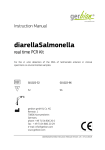
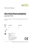
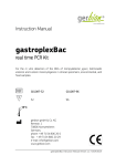
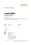
1
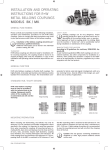
Installation and Operating Instructions
for R+W Metal Bellows Couplings
Models BK / MK
Please carefully and completely read the following installation, operation and maintenance procedures for the R+W safety couplings. Failure
to comply with these procedures may result in poor performance and/
or failure of the bellows coupling.
Installation of the bellows couplings should be performed by a qualified technician. Additional information
can be found in the individual product catalog, BK / MK.
Safety alert
Rotating couplings can be very dangerous. Proper guarding
should be in place at all times and is the responsibility of the
machine builder, user, or operator. Do not approach or touch a
coupling while it is rotating. Make sure the machine is “locked
out” and be accidentally started during installation or maintenance of the coupling.
Manufacturer’s declaration
Transport
R+W bellows couplings are delivered ready for installation. After incoming inspection, the coupling should be stored in its original packaging until ready for installation. A copy of this installation and operating manual
should be kept with the coupling.
According to EG guidelines for machinery 2006/42/EG, Appendix IIB
As per machinery guidelines (MR), shaft couplings are not considered
machines, but rather components for installation in a machine. Their
putting into operation is subject to the fulfillment of all requirements
of machinery regulations by or after integration into the final product.
General function
R+W metal bellows couplings are flexible shaft couplings.
The highly flexible, torsionally rigid stainless steel bellows provides
backlash free transmission of torque. The metal bellows compensates
for lateral, axial and angular misalignment, with very low restoring
forces. Several different hub designs are available to suit a variety of
applications.
Standard hub / shaft designs
flange mounting
tapered hub
clamping hub
conical clamping ring
fully split hub
expanding shaft
tapered conical sleeve
radial set screw
R+W metal bellows couplings must be used in accordance with the technical data in the catalog. Subsequent modification of
the coupling is not recommended and will void the warranty.
Mounting preparation
When mounting and dismounting, the bellows may only be deformed 1.5x
the maximum permissible misalignment values specified in the catalog.
It is important to avoid any excessive force when mounting the coupling.
All mounting surfaces including shafts, keys, bores and keyways must be
clean and free of burrs, nicks, and dents. Inspect shaft diameters, coupling
bore diameters, key / keyway dimensions and tolerances. All R+W coupling
bores are machined to ISO tolerance H7. The expanding shaft of the MK3 is
machined to ISO tolerance f7 and the BK7 expanding shaft is machined to
ISO tolerance h7. The overall clearance between the hub and shaft is maintained to 0.01 - 0.05 mm. A light coating of machine oil is recommended to
ease the mounting process and will not affect the clamping force of the hub.
CAUTION! Oils and greases containing molybdenum disulphide or other high pressure additives should not be used.
R+W
Mont.-Anl_MB-BK_E.indd 1
1
09.03.12 09:19
Mounting flange: Model BK 1
Figure 9
쐃
쐃
�
outer pilot
Mounting:
The BK1 can be piloted with either the ID or OD of the coupling hub. Mount the coupling to
the customer supplied flange and secure with mounting screws (4). Tighten the mounting
screws to the correct tightening torque, supplied by the customer, with a torque wrench.
Dismounting:
Simply loosen the flange mounting screws and remove the coupling.
inner pilot
Clamping hub connection: Model BK 2 / BKL / BKC / MK 2 / BKH / MKH / BKM / BKS
Figure 10
A
Spindle
Motor
A
Mounting:
Prior to mounting make sure that the shafts to be connected do not exceed the angular
or lateral misalignment limits for the coupling to be used. This data can be found in the
catalog. Slide the metal bellows coupling onto the motor shaft end. When the correct axial
position has been reached, tighten the clamping screw (A) to the correct tightening torque
as indicated in table 1 with a torque wrench. Insert the spindle shaft into the other end of
the coupling to the proper axial position. Make sure that the coupling is free of any axial
forces before tightening. Tighten the clamping screw (A) as above using a torque wrench to
the proper tightening torque. For the split hub model, it is necessary to maintain the proper
separation between shaft ends (dimension H in the catalog).
CAUTION: For the split hub design the shafts must extend into the coupling to the full width of the fully split clamping hubs.
Spindle
Motor
Dismounting:
Simply loosen the clamping screws and remove the coupling.
H
split hub
Tapered conical connection: Model BK 3
Figure 11
B
Spindle
Motor
Mounting:
Prior to mounting make sure that the shafts to be connected do not exceed the angular or
lateral misalignment limits for the coupling to be used.
Slide the coupling onto the motor shaft to the proper axial position. Using a torque wrench
tightening the clamping screws (B) in 3 steps with 1/3, 2/3 and full tightening torque in a
cross wise pattern. Tightening torque of the clamping screws is shown in table 1.
CAUTION: Overtightening of the clamping screws (B) can cause damage.
쐏
Dismounting:
Loosen the clamping screws (B) evenly. Use the three removal jack screws to remove the
conical sleeve. Pay attention to the equal force distribution of the removal jack screws.
Grease on the jack screw heads will enhance the friction. This results in less force being
required to remove the conical sleeve.
CAUTION: Prior to re-assembly make sure the three jack screws (4) are
turned back to their original position.
Tapered hub connection: Model BK 4
Figure 12
Fanuc - Motor
B
�
1:10
�
Mounting:
Prior to mounting make sure that the shafts to be connected do not exceed the angular or lateral misalignment limits for the coupling to be used. This data can be found in the catalog.
Slide the metal bellows coupling onto the motor shaft end. When the correct axial position
has been reached, tighten the nut (5) to the correct tightening torque as specified by the
customer with a torque wrench. Insert the second shaft into the other end of the coupling
to the proper axial position. Using a torque wrench, uniformly tighten the clamping screws
(B) using a cross-wise tightening pattern (as explained for the BK3) until all the clamping
screws are evenly tightened to the correct tightening torque as specified in table 1.
DIN 896 B
Dismounting:
Remove the conical sleeve as described for the BK3. To dismount the other end, loosen
the nut (5) that is axially securing the tapered shaft. Remove the tapered shaft with an
appropriate tool.
2
R+W
Mont.-Anl_MB-BK_E.indd 2
09.03.12 09:19
Conical clamping ring connection: Model BK 6 (axial blind mate)
C
Spindle
Motor
i i stop
� PPositive
�
Mounting:
The BK 6 uses a conical clamping with axial fastening screws. Slide the coupling half onto
the motor shaft to the proper axial position.
Using a torque wrench tighten the clamping screws (C) in 3 steps with 1/3, 2/3 and full tightening torque in a cross wise pattern. Tightening torque of the clamping screws are given in
table 1. The clamping ring (5) will come to a positive stop (6).
Figure 13
C
Dismounting:
Loosen the motor mounting screws. Remove the motor together with the male tapered
segment. Loosen the clamping screws (C). Use the three jack screws (7) to „back off“ the
conical clamping ring and remove the coupling.
�
Evenly loosen the fastening screws (C) (approx. 2 complete turns) and back out
the conical clamping ring with the removal jack screws (7). After removal, return
the removal jack screws to their original position.
Expanding shaft connection: Models BK 7 / MK 3 / MK 6
Figure 14
Mounting:
Completely insert the expanding shaft side of the coupling into the hollow bore. Using a
torque wrench, tighten the clamping screw (D) to the proper tightening torque as indicated
in table 1. Next insert the shaft end or encoder shaft into the other side of the coupling. Ensure that the shaft has been inserted to the proper axial position and that no residual axial
forces remain on the coupling. Using a torque wrench, tighten the clamping screw (A) to the
proper tightening torque as indicated in table 1.
Hollow shaft
A
Dismounting:
Simply loosen the clamping screws (A) and (D) and remove the coupling. It may be necessary
to apply axial pressure to the clamping screw (D) to remove expanding shaft.
D
Hub length
Radial set screw connection: Models MK 1 / MK 4
ISO 4029 E
E
E
�
Dismounting
groove
� Mounting:
�
�
Burr
Figure 15
A shaft groove or flat is not required
Slide the complete coupling onto the shaft end to the proper axial position. Using a torque
wrench, tighten the set screw(s) (E) to the proper tightening torque as indicated in table 1.
Insert the second shaft end to the proper axial position and ensure no residual axial forces
exist on the coupling. Tighten the set screw(s) using the same procedure as on the first side.
For series 10 and smaller couplings, each hub has one set screw, series 15 and larger have
two set screws per hub, 120 degrees apart.
- Series 10 and smaller: 1 x screw per hub
- Series 15 and up: 2 x screws per hub, 120 degrees apart
Dismounting:
Simply loosen the set screw(s) (E) and remove the coupling. R+W couplings incorporate a
unique dismounting groove that provides clearance for any burr caused by the setscrew (9).
Shaft groove or flat is not required.
Blind mate connection: Models MK 4 / MK 5 / MK 6 / BK 5 / BK 6
MK4
Miniature bellows coupling
Bellows coupling
Motor
Spindle
MK5 / BK5
MK6
BK6
press-fit length A
Single position
(standard)
Multi position
Multi position
(standard)
Single position
Figure 16
Pre-tensioning F
Figure 17
Mounting:
A shaft groove or flat is not required. Prior to mounting it is necessary to take into consideration the overall length
of the assembled coupling. The blind mate coupling requires a specific pre-tensioning (F) between the two coupling
halves to ensure backlash free operation. Mount the ”female” bellows body onto the spindle shaft to the proper axial
position. Tighten the clamping screw(s) per the mounting instructions for the coupling hub design. Mount the ”male”
tapered segment onto the motor shaft. The proper axial position of the coupling segment on the motor shaft is when
the motor is mounted and the coupling is compressed by the proper pre-tensioning value (F). When the coupling
segment is properly positioned, tighten the clamping screw to the proper tightening torque using a torque wrench.
The maximum misalignment values of the coupling will not be affected by the pre-tensioning.
R+W
Mont.-Anl_MB-BK_E.indd 3
3
09.03.12 09:19
Screw tightening torque / pre-tensioning
0.5
Series MK
1
5
10
15
20
45 100
Series BKC / BKS
15
Series BKM
20
2
Series BKL
4.5
10
Series BK
A
B
C
D
E
F
30
60
150
200
400
15
30
60
15
30
60
80
300
500
1000
150
80
300
150 200
300
500 800 1500 4000
Clamping screws
x
x
M2 M2 M2.5 M3 M4 M4 M5 M6 M8 M10 M10 M10 M10 M10 M12 M12 M12 M12 M16 M16 M20
x
Tightening torque (Nm)
x
x
0.43 0.43 0.85 2.3
4
4.5
x
Clamping screws
x
x
x
x
x
x
x
x
Tightening torque (Nm)
x
x
x
x
x
x
x
x
Clamping screws
x
x
x
x
x
x
x
x
M4 M5 M5
Tightening torque (Nm)
x
x
x
x
x
x
x
x
3.5 6.5
Clamping screws
x
x
M3 M3 M4 M4 M5 M6 M5 M6 M8
x
x
1.5 1.5
Tightening torque (Nm)
Clamping screws
3
4
Pre-tensioning
approx.
(mm)
8
50
70
75
85
70 120 120 130 125 200 250 470
x
x
x
x
M6 M6
x
x
x
x
x
12
14
x
x
x
x
M6
x
x
x
x
x
12
x
x
x
x
x
M10
x
4
15
6
8
8
M8
x
M8 M10 M12 M16
x
18
x
25
40
70 120
x
M8
x
M8
x
x
x
x
30
x
32
x
x
x
x
M12
x
x
x
x
x
11
8
14
38
x
x
x
x
65
x
x
120
x
x
x
x
x
M2 M2.5 M3 M3 M3 M4 M5 M6
x
x
x
x
x
x
x
x
x
x
x
x
x
x
x
x
x
x
x
x
x
x
x
x
x
x
x
x
x
x
x
x
1
1
x
x
x
1
x
x
1
x
1.2
x
x
x
Tightening torque (Nm) 0.35 0.75 1.3 1.3 1.3 2.5
x
x
0.4
x
6.5
40
M4 M5 M5
4
0.5 0.5 0.7
6
1
0.5 0.7
Table 1
Maximum shaft misalignments
R+W metal bellows couplings compensate for
lateral, axial, and angular shaft misalignment simultaneously.
In the section Technical Information within the product catalogs you will find the maximum permissible values for the three
types of misalignment. It is important to remain within these
limits to ensure long life and proper operation of the coupling.
Lateral misalignment ∆ Kr
CAUTION: Lateral misalignment has a negative effect on
the service life of the bellows. Exact alignment of the R+W
metal bellows coupling considerably increases the service life of the coupling. By reducing or eliminating lateral
misalignment, the radial load on the adjacent bearings is
eliminated while increasing service life and reducing heat.
Axial misalignment ∆ Ka
Angular misalignment ∆ Kw
Installation with intermediate flange
Open installation
Figure 19
Intermediate flange is fixed
Figure 20
Motor
centering pilot
Spindle
For high speed applications, we recommend aligning the
R+W coupling with dial indicators or a laser alignment tool.
Spindle
Motor
Spindle
dial indicator
Magnetic base
If an R+W metal bellows coupling is to be installed within an intermediate flange, it is important that the drive and driven shafts are
aligned as precisely as possible. The flange must be precision machined with centering pilots, and the mounting surfaces must be parallel to each other and perpendicular to the shaft axis.
If the R+W coupling is to be mounted between a foot mounted motor
and a gearbox, please take extra care during installation. Ensure that
the gearbox and motor shafts are properly aligned and the devices are
permanently mounted.
Maintenance
R+W Antriebselemente GmbH
Alexander-Wiegand-Str. 8 · 63911 Klingenberg
Tel. +49-(0) 93 72 – 98 64-0 · Fax +49-(0) 93 72 – 8 64 20
[email protected] · www.rw-kupplungen.de
4
The above-mentioned information is based on our present
knowledge and experiences and does not free the user of his
own regular checks. A legally binding guarantee is not given
even in regard to protection rights of Third parties.
599/02/12/5000
R+W metal bellows couplings are maintenance free as long as they are properly mounted and the maximum misalignment values are
not exceeded.
R+W
Mont.-Anl_MB-BK_E.indd 4
09.03.12 09:19