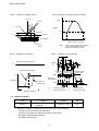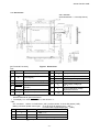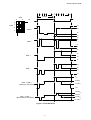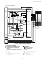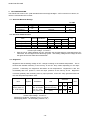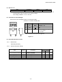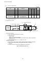
1
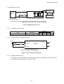
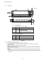
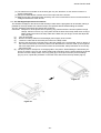
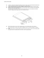
AN.No.G321EV-560E LIQUID CRYSTAL DISPLAY MODULE G321EV USER'S MANUAL Seiko Instruments Inc. AN.No.G321EV-560E NOTICE This manual describes the technical information, as well as the functions and operation of the G321EV Liquid Crystal Display Module made by Seiko Instruments Inc. Please read this manual carefully to familiarize yourself with the functions so you can make the best use of them. The descriptions here are subject to change without notice. Edition 1 Revision Record Revision Original Date June 1995 Seiko Instruments Inc. 1995 Printed in Japan -i- AN.No.G321EV-560E CONTENTS 1. SPECIFICATIONS 1.1 General ......................................................................................................... 1 1.2 Features ........................................................................................................ 1 1.3 Option Specifications .................................................................................... 1 1.4 Absolute Maximum Ratings (excluding CFL backlight) ................................ 2 1.5 Mechanical Characteristics ........................................................................... 2 1.6 Electrical Characteristics (excluding CFL backlight)..................................... 2 1.7 Optical Characteristics .................................................................................. 3 1.8 LCD Panel Lifetime ....................................................................................... 4 1.9 Dimensions ................................................................................................... 5 2. CIRCUIT STRUCTURE 2.1 Liquid Crystal Driving Circuit......................................................................... 6 2.2 Circuit Structure ............................................................................................ 8 2.3 Timing Characteristics .................................................................................. 12 2.4 Interface Circuit............................................................................................. 14 3. CFL BACKLIGHTING 3.1 Absolute Maximum Ratings .......................................................................... 18 3.2 Electrical Characteristics .............................................................................. 18 3.3 Brightness ..................................................................................................... 18 3.4 Service Life ................................................................................................... 19 3.5 Connector for CFL Backlight......................................................................... 19 3.6 Recommended CFL Inverter ........................................................................ 19 3.7 CFL Backlight Replacement Procedures...................................................... 23 4. NOTES .................................................................................................................. 25 INDEX - ii - AN.No.G321EV-560E 1. SPECIFICATIONS 1.1 General The G321E is a thin liquid crystal display (LCD) module that consists of a full dot-matrix LCD panel, CMOS LSIs, and a CFL backlight. The LCD panel features a wide viewing angle and high contrast. The full dot-matrix structure allows both graphics and character display. In addition, the display is clear and stable, with no image warping or position skew, because the display position is specified by the intersection of transparent electrodes in a matrix. 1.2 Features Full dot-matrix structure with 320 240 dots duty Four-bit parallel data input Two power supplies : VDD = 5 V, VLC = -24 V (for driving liquid crystal) Built-in CFL backlighting, high-brightness, side-lighting type, using one CFL Easy replacement of the CFL Weight : Approx. 195 g 1.3 Option Specifications Model name LCD Dot color* Background color* Viewing angle FSTN type G321EV5R000 (black and Transmissive, with CFL White Black 6 o'clock white) G321EV5B000 STN type (blue) backlighting (white), negative mode** Transmissive, with CFL White Blue 6 o'clock backlighting (white), negative mode** * The LCD colors are affected by temperature, so the colors at low or high temperature differ slightly from those in the above table. ** On a negative mode LCD, the dots are white when the display data is high, and black (G321EV5R000) or blue (G321EV5B000) when the display data is low. To get a positive display on a negative mode LCD, invert the display data before inputting it to the module. -1- AN.No.G321EV-560E 1.4 Absolute Maximum Ratings (excluding CFL backlight) Vss = 0 V Item Symbol Power supply voltage Conditions Min. Max. Unit VDD 0 6.0 V VLC VDD - 30.0 VDD V VDD - 30.0 VDD V -0.3 VDD+ 0.3 V 0 + 50 °C -20 + 60 °C ≤ 48 hrs +20 +85 %RH ≤ 1000 hrs +20 +65 %RH VO ≥ VLC VO Input voltage VIN Operating temperature Topr Storage temperature Tstg ≤ 65%RH Storage humidity 1.5 Mechanical Characteristics Item Standard 320 × 240 Dot configuration Module dimensions Viewing area (H×V) (H×V) Active display area Dot dimensions Dot pitch (H×V×T) (H×V) (H×V) Weight 1.6 [ mm ] 150.0 × 96.0 × 14.0 max. [ mm ] 103.0 × 80.0 [ mm ] 95.97 × 71.97 [ mm ] 0.27 × 0.27 [ mm ] 0.30 × 0.30 [ H : Horizontal V : Vertical dots g ] 195 typ. T : Thickness (max.) Electrical Characteristics (Excluding CFL Backlight) 1.6.1 FSTN type (Black and white, transmissive type) Vss = 0 V, Item Symbol Conditions to 50°C Min. Typ. Max. Unit 4.75 5.00 5.25 V -24.5 -24.0 -23.5 V VO VDD = 5 V VDD = 5 V VO ≥ VLC -23.0 -5.0 V High VIH VDD = 5 V ± 5% 0.8 VDD VDD V Low VIL VDD = 5 V ± 5% VDD= 5.0 V, VLC=-24.0 V VO=-15.6 V fFLM = 70 HZ, Ta = 25 °C 0 0.2 VDD V 6.4 15 mA 5.7 15 mA VDD = 5 V ± 5% 66.5 70 73.5 HZ VDD_ Power supply voltage Input voltage Ta = 0°C Current consumption* VLC IDD ILC Frame frequency fFLM * Display patterns : Checkered patterns Display data shift clock frequency : 3.0 MHZ -2- AN.No.G321EV-560E 1.6.2 STN type (Blue, transmissive type) Vss = 0 V, Ta = 0C to 50C Item Symbol Conditions VDD_ VLC Min. Typ. Max. Unit 4.75 5.00 5.25 V -24.5 -24.0 -23.5 V VO VDD = 5 V VDD = 5 V VO VLC -23.0 -5.0 V High VIH VDD = 5 V 5% 0.8 VDD VDD V Low VIL 0 0.2 VDD V Current consumption* IDD 6.4 15 mA ILC VDD = 5 V 5% VDD= 5.0 V, VLC=-24.0 V VO=-16.2 V fFLM = 70 HZ, Ta = 25 C 5.7 15 mA fFLM VDD = 5 V 5% 66.5 70 73.5 HZ Power supply voltage Input voltage Frame frequency * Display patterns : Checkered patterns Display data shift clock frequency : 3.0 MHZ 1.7 Optical Characteristics 1.7.1 FSTN type (Black and white, transmissive type) 1 / 240 duty, 1 / 13.1 bias, fFLM = 70 Hz, Vopr = VDD -VO, CFL Backlight : ON Item 1 Viewing angle Conditions Symbol 2 2-1 Contrast C Response time (rise) ton Response time (fall) toff Response time (rise) ton Response time (fall) toff 2.0 = 0 C Vopr=20.6 V = 0 = 0 = -10 =0 Vopr=20.6 V Vopr=20.6 V =0 =0 Vopr=22.4 V Temp. 25 C Min. 50 70 25 C 25 C 0C 5.0 Typ. 8.0 Max. Unit Reference deg. Notes 1 and 2 Note 3 ms Note 4 -20 230 350 150 230 1100 1700 500 750 Measuring instrument : Canon illuminometer LC-3S 1.7.2 STN type (Blue, transmissive type) 1 / 240 duty, 1 / 13.1 bias, fFLM = 70 Hz, Vopr = VDD -VO, CFL backlight: ON Item Symbol Response time ton 1 toff 2 (rise) Viewing angle Response time (rise) Contrast 1 t 2-on toff C Response time (rise) ton Response time (fall) toff Response time (rise) ton Response time (fall) toff Conditions ƒÇ = 0 C 0 • ¡ =2.0 Vopr=20.6 V =0 Vopr=21.2 V ƒÇ = 0 •¡ = 0 =0 V Vopr=22.4 =0 Vopr=21.2 V =0 =0 Vopr=21.2 V =0 =0 Vopr=22.8 V Temp. Min. •| Typ. Max. 230 350 -15 230 150 1100 Unit Reference Notes 1 deg. ms Note 4 and 2 1700 0•• •| 500 750 25C 2.0 3.0 Note 3 Measuring instrument : Canon illuminometer LC-3S 170 260 25C 190 290 ms Note 4 1100 1700 0C 500 750 25•• 25 C •| 20 •| 35 Measuring instrument : Canon illuminometer LC-3S -3- AN.No.G321EV-560E Note 1 : Definition of angles θ and φ Note 2 : Definition of viewing angles θ1 and θ2 Z (θ =0°) Cmax. Sensor θ θ1 Y ‘(φ =180°) θ2 Contrast C 2.0 LCD panel X (φ=90°) X’ θ2 θ1 CFL backlight φ Z’ Viewing angle θ (φ fixed) Y (φ=0°) (θ=90°) Note : Optimum viewing angle with the naked eye and viewing angle θ at Cmax. above are not always the same. Note 4 : Definition of response time Note 3 : Definition of contrast C 1/fFLM Vopr Brightness of selected dot (B2) Voltage C= Brightness of unselected dot (B1) (V) Brightness of selected dot Unselected state B2 (%) Selected state (display ON) Unselected state (display OFF) Bright Brightness (transmission) 100% 10% 90% Brightness Brightness of unselected dot Dark ton B1 0 Vopr ton Operating voltage (v) : Operating voltage : Response time (rise) toff fFLM toff : Frame frequency : Response time (fall) 1.8 LCD Panel Lifetime Item Lifetime* * Conditions 25°C±10°C <65%RH Standard Unit 100,000 or more hrs Definition of lifetime : the time up to occurrence of any of the following : ž Contrast reduces to 30% of the initial value. ž Current consumption becomes three times the initial value. ž Orientation deteriorates significantly. ž The display malfunctions. -4- AN.No.G321EV-560E 1.9 Dimensions Unit : mm/inch General tolerance : ± 0.5 mm(0.02inch) [I/O Terminal Functions ] CN1 No. Symbol Figure 1 Dimensions Function No. Symbol One-frame timing signal 8 D2 Display data input NC (or liquid crystal AC drive control signal) 9 D3 Display data input 10 VDD Power supply voltage (1):+5 V 11 VSS GND: 0 V 12 VLC Power supply voltage (2) : -24 V 13 VO Liquid crystal drive voltage adjustment terminal 14 FGND 1 FLM 2 M 3 CL1 One-common-line timing signal 4 CL2 Display data shift clock Display ON/OFF control DISPOFF terminal** 5 6 D0 Display data input 7 D1 Display data input Function Frame ground* * The FGND terminal is connected to the module metal frame. Use this terminal to ground the frame. ** The display is on when DISPOFF is H, and off when L. CN2 CFL connector: socket IL-G-3S-S3C2 ( JAE ), socket contact IL-G-C2-SC-10000 ( JAE ) Mating connector (board mount type): IP-G-3P-S3T2-E (straight type) ( JAE ) IL-G-3P-S3L2-E (right-angle type ) ( JAE ) No. Symbol Wire color Function 1 VFL black 2 NC 3 VFL1 Red GND*: 0 V NC CFL backlight drive signal * Not connected to VSS (GND) of CN1. -5- AN.No.G321EV-560E 2. CIRCUIT STRUCTURE 2.1 Liquid Crystal Driving Circuit The G321E LCD panel drive waveform is shown in Figure 2. Since DC voltage will damage the liquid crystal, AC voltage is applied between the two frames. The signal controlling this is the liquid crystal AC drive control signal M. Depending on the LCD panels, increasing the liquid crystal AC drive waveform frequency may improve the display quality. The G321E contains a circuit that generates AC drive control signal M’, which has a higher frequency than that of M. The frequency of the M’ signal is adjusted according to the LCD panel to provide the best display quality. The use of an external M signal is also possible if necessary. The liquid crystal driving circuit using an M’ signal does not require an M signal to be input. However, the interface circuit should be provided with M signal input for compatibility with the liquid crystal driving circuit using a M signal. The frame frequency is normally set to 70Hz5% to prevent screen flicker. The G321E has a 1/240 duty cycle, and the common electrodes are selected within a frame by time division from electrode 1 to electrode 240. This is called line sequential scanning. The voltage level of the segment electrodes determines whether or not the dots at the intersection of the segment electrodes are selected when the common electrode is selected. As shown in Table 1, there are six drive waveform voltage levels, Va to Vf. The voltage level is determined by the bias value. The voltage between the segment and common electrodes is then applied to the liquid crystal. The selection waveform for SEG0-COM0 and the non-selection waveform for SEG1- COM1 are shown in Figure 2. The size of the effective voltage of the waveform determines whether the liquid crystal under the selected dots is in the selection or non-selection state. Table 1 Va Common and segment selection level Vb Common non-selection level Vc Segment non-selection level Vd Segment non-selection level Ve Common non-selection level Vf Common and segment selection level In black-and-white negative mode, the dot is white when the display data is “1” and black when “0”. In blue negative mode, the dot is white when the display data is “1” and blue when “0”. -6- AN.No.G321EV-560E 0 0 SEG 1 2 1 2 3 239 0 1 2 3 239 1 frame M 0 COM 1 Va 2 3 COM Vb 0 Ve Vf Va Vb COM 1 Ve Vf Va Vc SEG Vd 0 Vf Va SEG Vc 1 Vd Vf Vopr 1/13Vopr SEG 0-COM 0 (Selection waveform) -1/13Vopr -Vopr 11/13Vopr 1/13Vopr SEG 1-COM 1 (Non-selection waveform) -1/13Vopr -11/13Vopr Figure 2 Drive Waveform -7- AN.No.G321EV-560E 2.2 Circuit Structure The G321E consists of common drivers, segment drivers, a bias voltage generation circuit, an M’ generation circuit and a Vopr control circuit. Figure 3 shows the block diagram for the G321E. When an M signal is used instead of an M’ signal, the M signal is directly input to the segment drivers and the common drivers. D0D3 CL2 CL1 M’gen- M’ eration circuit M(NC) FLM DISPOFF VSS Segment driver 2 Segment driver 3 Segment driver 4 80 80 80 80 Common driver 2 80 Va Vc Vd Vf 320240 full dot-matrix LCD Common driver 3 80 Va, Vb, Ve, Vf Bias voltage generation circuit VLC Segment driver 1 Common driver 1 80 VDD VO VSS Common driver: HD66205( or MSM6598) Segment driver: HD66204( or MSM6599B) Vopr(Va-Vf) control circuit Figure 3 Block Diagram for G321E -8- AN.No.G321EV-560E (1) Common driver (HITACHI HD66205 or OKI MSM6598) A common driver (CD) is a CMOS IC with 80 drive outputs. internal registers are connected to each other. The G321E has three CDs, whose They operate as follows. Input one-frame timing signal (FLM) is taken into the internal shift register by the falling edge trigger of the one-common-line timing signal (CL1), and sequentially shifted. After 240-CL1 input, the next FLM is input and the same operation is repeated. As shown in Table 2, the common output is selected according to the shift register contents and the internally-generated liquid crystal AC drive control signal (M’) in the drive circuit, and the common drive waveform are formed. Table 2 DISPOFF Shift register content M’ COM output H Va L Vf H Ve L Vb × Va H H L × L ×: Invalid The common output is controlled by the DISPOFF signal; when the DISPOFF signal is low, the common output is Va, irrespective of the shift register contents or the M’ signal. (2) Segment driver (HITACHI HD66204 or OKI MSM6599B) A segment driver (SD) is a CMOS IC with 80 drive outputs. The G321E has four SDs, which operate as follows. Input four-bit data is sequentially taken into the internal register by the falling edge trigger of the display data shift clock (CL2). The SDs have a chip enable function. into SD1, the next bit of data is automatically taken into SD2. data can be taken. trigger of CL1. After 80 bits of data are taken Since G321E has four SDs, 320 bits of The display data taken into the internal register are latched by the falling edge The segment output is selected according to this display data and M’ in the drive circuit, and the segment drive waveform is formed as shown in the Table 3. Table 3 DISPOFF Display data M’ SEG output H Vf L Va H Vd L Vc × Va H H L L × ×: Invalid -9- AN.No.G321EV-560E The segment output is controlled by the DISPOFF signal. When the DISPOFF signal is low, Va is output to the segment, irrespective of the display data and of the M’ signal. Therefore, by bringing the DISPOFF signal to low, Va is output both to the common and to the segment electrodes, making the voltage applied to the liquid crystal zero, and the display goes off. The relationship between the display data and display screen is shown below.. 1 1 2 3 4 5 6 D3 D2 D1 D0 D3 D2 320 320×240 dots (1/240 duty ) 240 Figure 4 (3) Vopr control circuit Display screen contrast and viewing angle are affected by changes in the liquid crystal operating voltage (Vopr). As shown in Figure 5, external VLC is supplied to the operational amplifier and Vopr (Va to Vf ) is generated and applied to the LCD panel. VDD= 5 V R1= 18 kΩ Vopr : ( Va-Vf ) – + VO VR= 10 kΩ R2= 3.9 kΩ Operational amplifier VLC= -24 V G321E Figure 5 Also, display screen contrast and viewing angle are influenced by the ambient temperature. The recommended Vopr level at different temperatures is as follows. 0 25 50 FSTN (Black and white) 22.4 20.6 19.0 STN (Blue) 22.8 21.2 19.7 Temperature (°C) Vopr (V)* * Vopr ≈ VDD-VO - 10 - AN.No.G321EV-560E (4) Bias voltage generation circuit Six voltage levels, Va to Vf, are applied to the common and segment drivers. The voltage is generated through operational amplifiers by resistance division from the liquid crystal operating voltage (Vopr). Here, an operational amplifier is used as a voltage follower. VDD Va R1 C Vb + R1 C Vc + Vopr R2 C Vd + R1 C Ve + R1 Operational amplifiers C Vf 1 / 13.1 bias : R2= (13.1-4)R1= 9.1 R1 Figure 6 Bias Voltage Generation Circuit (5) M’ generation circuit As Figure 7 shows, the M' generation circuit performs an XOR on the one-common-line timing signal (CL1) (on which A time division is performed) and the one-frame timing signal (FLM) (on which B time division is performed), and outputs liquid crystal AC drive control signal M’. Values A and B are set according to the LCD panel so that the best display quality can be obtained and the drive voltage can be changed. CL1 A frequency divider FLM B frequency divider M’ XOR gate Figure 7 M’ Generation Circuit - 11 - AN.No.G321EV-560E 2.3 Timing Characteristics 2.3.1 Power ON/OFF and Signal Input Timing Power ON/OFF and signal input should be performed according to the timing shown in the figure below in order not to damage the LCD driving circuit and the LCD panel. VDD +5 V GND t1 t1 GND VLC VLC t2 t2 +5 V Input signals GND DISPOFF t3 t2 +5 V GND t1 0 ms, t2 0 ms, t3 20 ms Figure 8 Power ON/OFF and Signal Input Timing 2.3.2 Timing Characteristics Ta = 0C to 50C VDD = 5.0 V5% VSS = 0 V Item Symbol Min. Typ. Max. Unit FLM cycle time tCFLM 13.6 14.3 15.0 ms CL1 cycle time tCCL1 10 59.6 s CL1 high level width tWCL1H 50 ns CL1 low level width tWCL1L 1000 ns FLM setup time tFLMS 100 ns FLM hold time tFLMH 100 ns CL1, CL2 rise time tR 30 ns CL1, CL2 fall time tF 30 ns tCCL2 125 ns CL2 high level width tWCL2H 45 ns CL2 low level width tWCL2L 45 ns CL2 setup time tDS 20 ns CL2 hold time tDH 20 ns CL2 rise to CL1 rise tLD ns CL2 fall to CL1 fall tSL 80 ns CL1 rise to CL2 rise tLS ns CL1 fall to CL2 fall tLH 80 ns CL2 cycle time - 12 - AN.No.G321EV-560E Timing Chart 1: Timing of Signal Input Into Common Driver 1 frame: tCFLM FLM 240 pulses CL1 FLM tFLMS tFLMH tCCL1 tR tF CL1 tWCL1L tWCL1H Figure 9 Timing Chart 2: Timing of Signal Input Into Segment Driver M CL1 CL2 N 1 D0 to D3 4 2 3 N 1 1 2 N 1 2 2 3 N 1 2 4 1 N=20 1 4 : Segment driver cascade number tWCL1H tWCL1L CL1 tLS tLD tSL tLH tCCL2 CL2 tR tF tDS D0 to D3 Figure 10 - 13 - tWCL2L tDH tWCL2H AN.No.G321EV-560E 2.4 Interface Circuit 2.4.1 Interface with MPU signal The G321E is controlled by the MPU circuit, whose interface is easily set up when the LCD controller is used. The LCD controller has basic functions such as receiving information related to the display from the MPU circuit, sending display timing signals and display data to the LCD module, as well as other functions such as cursor display. The G321E must use an LCD controller conforming to the following: For a full dot-matrix LCD module Where data is transferred to the LCD module in four-bit parallel Where G321E display screen has 1/240 duty The following section gives examples of interfaces using the Oki MSM6255GSK, Seiko Epson SED1330F, and Hitachi HD64646FS controllers. - 14 - AN.No.G321EV-560E (1) OKI MSM6255GSK MPU MSM6255GS CS DIEN WR RD DB0∼DB7 Data bus RD0∼RD7 G DI OE G CG ROM WE RA0∼RA3 Display RAM A0∼A15 DC power supply +5 V GN -24 V Figure 11 Interface Circuit With MSM6255GSK Features of the MSM6255GSK: • Interface with 80-series MPU possible • Cursor ž ON/OFF ž Blinking speed, form, and position are programmable • Scrolling and paging • CMOS process • 5-V single power supply - 15 - FRP FRMB LIP CLP 1 FLM 2 M 3 CL1 4 CL2 5 DISPOFF UD0 6 D0 UD1 D1 7 UD2 D2 8 UD3 D3 9 VDD 10 VSS 11 R1 VLC 12 VO 13 VR R2 MA0∼MA15 Address bus G321E R1= 18 kΩ R2= 3.9 kΩ VR= 10 kΩ AN.No.G321EV-560E (2) SEIKO EPSON SED1330F MPU SED1330F CS R/W A0 E RES D0D7 Data bus VD0VD7 G321E YD WF LP XSCL XD0 XD1 XD2 XD3 VR/W VR VA0VA15 DC power supply +5 V GND -24 V Figure 12 Interface Circuit With SED1330F Features of the SED1330F: Interface with 80-series or 68-series MPU possible Built-in character generator ROM: 160 kinds External character generator CG RAM : (816 dot matrix)64 kinds CG ROM : (816 dot matrix)256 kinds Layered mode : AND, OR, XOR, “preferred” OR CMOS process Scrolling (vertical and horizontal) 5-V single power supply - 16 - R2 FLM M CL1 4 5 6 CL2 DISPOFF 7 8 9 R1 Display RAM 1 2 3 10 11 12 13 D0 D1 D2 D3 VDD VSS VLC VO R1= 18 k R2= 3.9 k VR= 10 k AN.No.G321EV-560E (3) HITACHI HD64646FS MPU HD64646FS CS, RD, WR RES DB0DB7 Data bus CUDISP Selector MD8MD15 Selector MD0MD7 CH / GR G321E FLM M CL1 CL2 LU0 LU1 LU2 LU3 WE RA0RA4 CG ROM CS VR CS R2 A-RAM V-RAM 1 FLM 2 M 3 CL1 4 CL2 5 DISPOFF 6 D0 D1 7 D2 8 D3 9 VDD 10 VSS 11 R1 VLC 12 VO 13 R1= 18 k R2= 3.9 k VR= 10 k RS MPX Address A A 0 15 bus MA0MA15 A0 DC power supply +5 V GND -24 V Figure 13 Interface Circuit With HD64646FS Features of the HD64646FS: Interface with 80-series MPU possible Layered mode : OR (character and graphics) Character reverse, blinking, all black, all white Cursor ON/OFF Blinking speed, form and position are programmable - 17 - Character font Vertical : 1 to 32 dots Horizontal : 8 dots Scrolling Vertical : smooth or character unit Horizontal : character unit CMOS process 5-V single power supply AN.No.G321EV-560E 3. CFL BACKLIGHTING The G321E has a built-in CFL (cold cathode fluorescent lamp) backlight. A CFL inverter is not built in, so use the recommended CFL inverter. 3.1 Absolute Maximum Ratings Item Circuit voltage Lamp current Frequency Symbol VS IFL fFL Ta=25C Unit V rms mA rms kHz Rating 2000 max. 10 max. 100 max. 3.2 Electrical Characteristics Item * ** Symbol Conditions min. 240 2.8 41 Standard typ. 270 3.1 47 max. 300 3.4 53 650 Unit Lamp voltage* VFL V rms Ta=25C Lamp current* IFL mA rms Ta=25C Frequency* fFL kHZ Ta=25C Starting voltage** VS V rms Ta=0C CFL inverter : INVC 303 (HITACHI) Inverter input voltage : VIN=24.0 V With the rise in voltage between the CFL terminals, the glow discharge is generated at the CFL electrodes, and CFL lights as this discharge grows. The starting voltage is the voltage at which the light has become stable and maintainable. 3.3 Brightness Brightness and the starting voltage of CFL change according to the ambient temperature. This is because the radiation efficiency of the mercury in the CFL lamp varies depending on the vapor pressure. Particularly, the brightness decreases at low temperatures. Brightness is also low immediately after CFL power-on, since the vapor pressure of the mercury is low. Brightness increases gradually with increasing mercury vapor pressure, as the CFL lamp generates heat and thus the lamp wall temperature rises. Item Brightness* ( At the center of the LCD surface) Symbol Bp Conditions Ta=25 C 3 C 30% to 85%RH 30 min. after CFL power ON Standard LCD FSTN type (black and white) STN type (blue) * CFL inverter : INVC303 (HITACHI) Inverter input voltage : VIN=24.0 V LCD driving conditions : optimum Vopr, fFLM= 70 HZ LCD display pattern : All ON display ( All data =”H”) - 18 - min. typ. 50 90 100 130 Unit max. cd/m2 AN.No.G321EV-560E 3.4 Service Life Item Conditions Rating Unit Service life * 10,000 min. h Ta=25C3C Time until the brightness decreases to half of the initial brightness, or time until the CFL is not lit because of the increase in CFL starting voltage. CFL driving conditions : IFL=3.1 mA rms * 3.5 Connector for CFL Backlight Connector for CFL backlight: Socket IL-G-3S-S3C2 (JAE) Contacts IL-G-C2-SC-10000 (JAE) 1 2 3 1 No. Signal Wire color 1 VFL Black 2 NC 3 VFL1 Red * 3 Functions Ground* : 0 V NC CFL backlight drive signal IFL=3.1 mA rms, fFL=47 kHZ Not connected to the LCD driver ground Figure 14 3.6 Recommended CFL Inverter 3.6.1 Model name INVC303 (HITACHI) 3.6.2 Absolute maximum ratings Item Symbol Power supply voltage VIN Operating temperature Storage temperature Operating humidity Storage humidity Topr Tstg Hopr Hstg Conditions Ta=0C to 50C, GND=0 V 20%RH to 85%RH No freezing or condensation No freezing or condensation No freezing or condensation No freezing or condensation - 19 - Standard min. max. 0 26.4 0 -20 30 20 50 60 65 85 Unit V C C %RH %RH AN.No.G321EV-560E 3.6.3 Electrical characteristics Ta=25°C Item Power supply voltage Power supply current*1 Input current*1 No load output voltage*2 Output current*1 Oscillation frequency*1 Starting characteristics at low temperature *1 *2 Conditions VIN IIN ICONT VO IFL fFL min. 21.6 1.3 2.8 41 VIN=24.0 V CFL : ON VIN=24.0 V VIN=24.0 V VIN=24.0 V VIN=24.0 V, Ta=0°C Load : CFL backlight unit BL-5/ASD(HITACHI) Standard typ. 24.0 60 1.5 1000 3.1 47 Unit max. 26.4 V 70 mA 1.7 mA V rms 3.4 mA rms 53 kHZ 2 sec. Measurement circuit 1 Measurement circuit 2 (1) Measurement circuit 1 (fFL: oscillation frequency) (IIN: power supply current) A + DC power supply +24V CN11-1 l1 F VFL1 VIN CN12-3 R: 3.3 kΩ – SW CN11-2 CONT CN12-1 GND CFL VFL l3 A CN11-3 (IFL: output current) Inverter l2 ž Measuring conditions • Load: CFL03ž88EX57G/L(tube) for G321EV ‚ Output lead wires ž Type: UL1015 ž Length: l1=200 mm, l2+l3=200 mm ž Connection : Lead wires should be connected to the CFL without being bound as shown above. ƒ CN11-2 terminal: GND: CFL is on, OPEN: CFL is off ž Measuring instruments • Power supply current: Digital voltmeter TR-6853(TAKEDA RIKEN) or equivalent ‚ Output current: High-frequency AC ammeter 2016 class 1.0 (YEW) or equivalent ƒ Oscillation frequency: Multicounter 255(KIKUSUI) or equivalent Figure 15 Measurement Circuit 1 - 20 - AN.No.G321EV-560E (2) Measurement circuit 2 High-pressure probe CN11-1 + DC power supply 24 V CN11-2 – (VO) CN12-3 SW R: 3.3 kΩ Synchroscope CN12-1 CN11-3 Inverter ž Measuring instruments À No load output voltage: Synchroscope: IWATSU DS-6121A or equivalent High-pressure probe: IWATSU HV-P30 or equivalent Figure 16 Measurement Circuit 2 3.6.4 3.6.5 Temperature of transformer Item Conditions Temperature of transformer Ta=50°C, VIN=24 V Standard typ. max. 95 min. Unit °C Inverter connection diagram (INVC303) +24 V • VIN R* VFL ƒ VFL1 VFL1 INVC303 ‚ CONT ƒ GND * • VFL Connect a current-limiting resistor. ICONT: 1.3 mA to 1.7 mA (1.5 mA typ.) Figure 17 Inverter Connection Diagram 3.6.6 Backlight ON/OFF control The ON and OFF of the backlight is controlled using CONT pin; the backlight is on when CONT pin is connected to GND and off when CONT pin is open. - 21 - AN.No.G321EV-560E Dimensions 1 2 3 4.50.5 3 2 1 4.50.5 70.50.2 79.50.5 (4.5) 200.5 2-4.00.1 110.2 CN12 CN11 Unit: mm (4.5) 3.6.7 10.0 max. (1.2) 2.0 max. 7.5 max. 6.8 max. 8.0 max. CN 11 : 175487-3(AMP) Mating connector : 173977-3(AMP) Pin No. Signals 1 VIN 2 CONT 3 GND Functions Power supply voltage: +24 V Backlight on/off control ON: GND, OFF: OPEN Ground: 0 V CN 12 : IL-G-3P-S3L2-E(JAE) Pin No. Signals Functions 1 VFL Output: GND 2 NC 3 VFL1 Output: high voltage Figure 18 3.6.8 Precautions in using the inverter (1) As the output of the inverter is high voltage, never touch it. (2) When connecting the inverter to the CFL, the following must be considered to avoid stray capacity effects: Do not twist together or tie the CFL connector cables. Metal plates and metal foils, if located close to the CFL and its wiring, affect the brightness and the starting voltage of the CFL. Connect the CFL connector directly to the inverter output connector. Do not use an extension cable. Be aware of the proximity of other parts and the casing to the secondary wiring of the inverter, the potential of these parts may significantly affect the electrical characteristics and startability of the inverter. - 22 - AN.No.G321EV-560E (3) The transformer mounted on the inverter gets very hot; therefore, do not use the inverter in a closed, small space. (4) Always use AWG No.26 or thicker wire on the input side of the inverter. (5) Make sure that the fluctuating load caused by use of the inverter does not turn into a fluctuation of voltage and affect the other circuits. 3.7 CFL Backlight Replacement Procedures The G321EV backlight is structured so that the lamp holder and the light guide can be divided, making it possible for the lamp holder with a built-in lamp to be replaced without disassembling the module. The CFL backlight replacement procedures are as follows: CAUTION: Always turn off the power before replacing any parts because the inverter operates at high voltage. Also do not force any of the parts around the base of the lamp cable when moving it. While holding the mold of the lamp cable at the base with your finger, loosen and adjust the other the parts. (1) Turn off the power. (2) Remove the lamp cable from the backlight power supply of the inverter. (3) Loosen the cable that is secured by the hook on the lamp holder. (4) Remove the two plastic rivets that secure the lamp holder to the circuit board. Push on the tip of the rivets to loosen them, and then pull them out. Because the rivets are made up of two pieces that come apart when you remove them from the circuit board, take precautions not to lose any part of the rivets. (5) The lamp holder is clamped on to the light guide in two places. While holding the board with your fingers so it does not move, first, wedge a flat-head screwdriver into the space between the board and one end of the lamp holder; next, very gently pry it loose (do not force it) from the fittings (Fig.19) ; then, repeat the procedure on the other end; and remove the lamp holder (Fig.20). Figure 19 Figure 20 - 23 - AN.No.G321EV-560E (6) (7) (8) Loosen the cable of the replacement lamp so that it is easy to slip around the board. Because the cable is held tightly by the hook, pull it through the loop and loosen it. Loop both wires around the board and through the notches so that the plug is under the board. Doing one side at a time, align the clamps of the lamp holder with the notches on the light guide and snap on the lamp holder (Fig.21). If the light guide moved when you removed the lamp holder and you are unable to locate the notches it, slightly slide the light guide up to reveal the notches. Figure 21 (9) (10) Reinsert both plastic rivets in their original positions in the following order: bush then pin. If any of the holes on either of the parts are unaligned, then move the lamp holder to align the holes. Take up the slack on the lamp cable that goes through the notches on the circuit board and back through the hook of the lamp holder, and return it to its original position. - 24 - AN.No.G321EV-560E 4. NOTES Safety If the LCD panel is damaged, be careful not to get the liquid crystal in your mouth and not to be injured by crushed glasses. If you should swallow the liquid crystal, first, wash your mouth thoroughly with water, then, drink a lot of water and induce vomiting; and then, consult a physician. If the liquid crystal should get in your eye, flush your eye with running water for at least fifteen minutes. If the liquid crystal touches your skin or clothes, remove it and wash the affected part of your skin or clothes with soap and running water. High voltage is present between CFL electrodes. To prevent electric shock, do not touch the wiring while the power is on. Be sure to turn the power off when connecting or disconnecting the connector. Use the LCD module within the rated voltage to prevent overheating and/or damage. Also, take steps to ensure that the connector dose not come off. Handling Avoid static electricity, as this can damage the CMOS LSI. The LCD panel is made of plate glass; do not hit or press against it. Do not remove the panel or frame from the module. The polarizer on the display is very fragile; handle it very carefully. Mounting and Design Mount the module using the specified installation sections and holes. To protect the module from external pressure, put a plate of transparent material such as acrylic or glass over the display surface, frame, and polarizer. Leave a small gap between the transparent plate and the module. Example Small gap Transparent plate Exterior surface Module Screw Keep the module dry. Condensation can damage the transparent electrodes. If the CFL lamp and its wiring are located close to a metal plate or metal foil, the stray capacity will cause the voltage to fall, which will decrease the brightness and increase the starting voltage. Be careful in designing the casing and the CFL wiring. - 25 - AN.No.G321EV-560E Storage Store the module in a dark place where the temperature is 25C 10C and the humidity is below 65%RH. Do not store the module near organic solvents or corrosive gases. Do not crush, shake, or jar the module or its components. Black or white air-bubbles may be produced if the module is stored for a long time in the lower temperature or mechanical shocks are applied onto the module. Cleaning Do not wipe the polarizer with a dry cloth, as it may scratch the surface. Wipe the module gently with a soft cloth soaked with a petroleum benzine. Do not use ketonic solvents (ketone and acetone) or aromatic solvents (toluene and xylene), as they may damage the polarizer. - 26 - AN.No.G321EV-560E Index -BBacklight ON/OFF control .....................................................................................................21, 22 Bias value ......................................................................................................................................6 Bias voltage generation circuit ................................................................................................8, 11 Block diagram................................................................................................................................8 Brightness ...................................................................................................................................18 -CCFL backlight drive signal .......................................................................................................5, 19 CFL backlighting......................................................................................................................1, 18 CFL inverter ..........................................................................................................................18, 19 Chip enable function......................................................................................................................9 Cleaning ......................................................................................................................................26 Common drive waveform ..............................................................................................................9 Common driver ....................................................................................................................8, 9, 13 Connector for CFL backlight........................................................................................................19 Contrast .....................................................................................................................................3, 4 Current consumption .....................................................................................................................3 -DDefinition of contrast......................................................................................................................4 Definition of response time............................................................................................................4 Definition of viewing angles...........................................................................................................4 Display data input ..........................................................................................................................5 Display data shift clock..............................................................................................................5, 9 Display ON/OFF control terminal ..................................................................................................5 Drive waveform .........................................................................................................................6, 7 -EEffective voltage ............................................................................................................................6 -FFlicker ............................................................................................................................................6 Frame frequency ...............................................................................................................2, 3, 4, 6 Frame ground ................................................................................................................................5 FSTN ...............................................................................................................................1, 2, 3, 10 -HHITACHI HD64646FS ...........................................................................................................14, 17 AN.No.G321EV-560E -IInput current ................................................................................................................................20 Input voltage ..............................................................................................................................2, 3 Input signal ..................................................................................................................................12 I/O terminal functions ....................................................................................................................5 -LLamp current ...............................................................................................................................18 Lamp voltage ...............................................................................................................................18 LCD controller..............................................................................................................................14 Lifetime ..........................................................................................................................................4 Liquid crystal drive voltage adjustment terminal ...........................................................................5 Liquid crystal AC drive control signal ..............................................................................5, 6, 9, 11 Liquid crystal operating voltage...................................................................................................10 -MM’ generation circuit ................................................................................................................8, 11 -NNegative mode ..........................................................................................................................1, 6 Non-selection waveform............................................................................................................6, 7 -OOKI MSM6255GSK ...............................................................................................................14, 15 One-common-line timing signal...........................................................................................5, 9, 11 One-frame timing signal ......................................................................................................5, 9, 11 Operating humidity ......................................................................................................................19 Operating temperature ............................................................................................................2, 19 Operational amplifier .............................................................................................................10, 11 Output current..............................................................................................................................20 -PPositive mode ............................................................................................................................1, 6 Power supply current...................................................................................................................20 Power supply voltage ..........................................................................................2, 3, 5, 19, 20, 22 -RResistance division......................................................................................................................11 Response time (fall) ..................................................................................................................3, 4 Response time (rise) .................................................................................................................3, 4 AN.No.G321EV-560E -SSegment drive waveform...............................................................................................................9 Segment driver ....................................................................................................................8, 9, 13 SEIKO EPSON SED1330F ...................................................................................................14, 16 Selection waveform ...................................................................................................................6, 7 Service life ...................................................................................................................................19 Side lighting ...................................................................................................................................1 STN ...................................................................................................................................1, 3, 10 Storage ........................................................................................................................................26 Storage humidity......................................................................................................................2, 19 Storage temperature ...............................................................................................................2, 19 -TTemperature of transformer ........................................................................................................21 -VViewing angle ........................................................................................................................1, 3, 4 Vopr control circuit...................................................................................................................8, 10 Seiko Instruments Inc. Head Office Components Overseas Sales & Marketing Department 31-1, 6-chome, Kameido, Koto-ku, Tokyo 136, Japan Phone: (03) 3682-5201 FAX: (03) 3637-0117 Seiko Instruments U.S.A. Inc. Electronic Components Division 2990 W. Lomita Blvd., Torrance Calif. 90505 Phone: 310-517-7770 FAX: 310- 517-7792 Seiko Instruments GmbH Siemensstra e 9, 6078 Neu-Isenburg, Germany Phone: 49-6102-297-0 FAX: 49-6102-297222 Seiko Instruments ( H. K. ) Ltd. Sales Division 4-5/F, Wyler Centre 2, 200 Tai Lin Pai Road, Kwai Chung, N.T., Kowloon, Hong Kong Phone: 852-4218611 FAX: 852-4805479 Seiko Instruments Taiwan Inc. 5F-1 No. 99, SEC.2, Chung Shan N. Rd., Taipei 104, Taiwan, R.O.C. Phone: 886-2-563-5001 FAX: 886-2-521-9519