1
®
GB
OPERATING INSTRUCTIONS
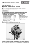
LEISTER Cosmo
Automatic wedge welding machine
Please read operating instructions carefully
before use and keep for further reference
APPLICATION
The LEISTER Cosmo is an automatic wedge welding machine for overlap
welding of geomembrane liners for earthwork and civil engineering.
• Thermoplastic lining membranes
Polyethylene high density
PE-HD
Polyethylene low density
PE-LD
Chlorinated polyethylene
PE-C
Polypropylene
PP
• Type of seam
welding seams are produced
in accordance with DVS 2225
part I and BAM.
Other dimensions are possible
on request.
DVS: German Welding Association
BAM: Federal Institute for Materials Research and Testing, Berlin
LEISTER Process Technologies, Riedstrasse, CH-6060 Sarnen / Switzerland
Tel. + 41 41 662 74 74 Fax + 41 41 662 74 16 www.leister.com
[email protected]
1
WARNING
Danger ! Unplug the tool before opening it as live
components and connections are exposed.
Incorrect use of the hot air tool can present a fire and
explosion hazard especially near combustible materials
and explosive gases.
Do not touch the hot air wedge when hot as it can
cause burns. Allow the tool to cool down.
Connect tool to a receptacle with protective earth
terminal. Any interruption of the protective conductor
inside or outside the tool is dangerous !
Line/mains extension cables must always have a protective ground conductor !
CAUTION
230
The voltage rating stated on the tool should correspond
to the mains voltage.
FI
For personal protection, we strongly recommed the tool
be connected to an RCCB (Residual Current Circuit
Breaker) before using it on construction sites.
The tool must be operated under supervision.
The radiating heat can ignite combustible materials.
Protect the tool from damp and wet.
The tool is CCA certified (CENELEC Certification Agreement).
Technical Data
Voltage
Power consumption
Capacy
Temperature
Welding pressure
Drive
Overlap width
Material thickness
Size
Weight
2
V~
Hz
W
°C
N
m/min.
mm
mm
mm
kg
230
50 / 60
2000
max. 450 stepless
max. 2500 stepless
0,5 – 5,0 stepless
180
1,5 – 3,0
600 × 380 × 450
32,0
DESCRIPTION OF FUNCTIONS
LEISTER Cosmo
• Heating System → The hot wedge temperature is steplessly adjustable and
electronically controlled. As required, the hot wedge can be steplessly
adjusted to match the material thickness.
Heating system cross sectional diagram
Pinch rollers
Upper geomembrane liner
Upper drive/
pressure roller
Welding
direction
Adjustment
nut for hot
wedge
Hot wedge
Lower drive/
pressure roller
Lower geomembrane liner
Guide roller, rear
Guide roller, front
• Welding pressure → steplessly adjustable. The welding pressure is transmitted
via the toggle lever to the pressure rollers. The swivel-head guarantees an
even seam thickness reduction on both welded sections (C and D) as well as
on a welded seam without test channel.
This allows T-joints to be welded easily. During the welding process the pressure is matched linearly to the change in thickness of the geomembrane
liner.
Cross-sectional diagram of an overlap weld
Seam thickness reduction = A – B
A : Thickness of upper and lower
geomembrane liner
B : Thickness of welding seam
C : Welded section 1
D : Welded section 2
E : Test channel
C
D
B
B
A
E
• Drive → electronically steplessly adjustable and electronically controlled.
Digital display of SET and ACTUAL value. The power transmission works through
a three stage planetary gear. Should rippling occur in the laid-out geomembrane liners, the upper or lower drive/pressure roller can be switched over
alternately.
3
DESCRIPTION OF FUNCTIONS
LEISTER Cosmo
• Welding seam geometry → The proof of quality in a welding seam (peel test,
tensile test) depends upon the thickness reduction in the area of the seam.
With a seam thickness reduction ranging between 0.2 – 0.8 mm, the welding
seam geometry is within the permissable range (DVS 2225 part II, BAM). This
permissable range reflects the optimum interaction of the welding parameters for temperature, welding pressure and speed during the welding process.
Cross-sectional diagram of an overlap weld
D
C
D
B
A
Seam thickness reduction = A – B
A : Thickness of upper and lower
geomembrane liner
B : Thickness of welding seam
C : Width of test channel 15 +/– 2 mm
D : Width of weld ≥ 15 mm
• Monitoring the welding seam → Contactless recording of the seam thickness
reduction data, which is displayed digitally for the welding operator during
the welding operation. Additionally, the seam thickness reduction is graphically recorded onto a paper print out continuously during the welding
operation.
• Speed control system
The influence of weather such as sun, shade, wind and moisture, which cause
a temperature change in the lining membrane during the welding process,
can lead to weld faults. The Cosmo speed control system interprets the data
from the continuous measurement of the welding seam geometry. Through
automatic adjustment of the welding speed, such weld faults are avoided.
The welding operation can be done either with or without the speed control
system. If the lower seam thickness reduction tolerance is exceeded, the
welding speed slows down automatically; if the upper seam thickness
reduction tolerance is exceeded, the welding speed is increased.
4
DESCRIPTION OF TOOL
LEISTER Cosmo
11
10
5
24
8
25
3
2
22 23 21
9
16
1
4
7
15
14
6
12
29
17
20
26
27
18
19
1. Cable to mains
2. Cable holder
3. Housing for drive motor
4. Ventilator grill
5. Carrying handle
6. Handle
7. Main switch
8. Display
9. Keyboard
10. Protection cover (printer)
11. Printer
12. Hot wedge
13. Adjustment nut for hot wedge
14. Guide roller, front
15. Guide roller, rear
16. Tension lever for welding pressure
28
13
17. Hand wheel for stepless
adjustment of the welding pressure
18. ON/OFF switch lever for upper or
lower drive/pressure roller
19. Locking device for switch lever (18)
20. Front roller
21. Rear roller
22. Lower drive/pressure roller
23. Upper drive/pressure roller
24. Swivel head
25. Sensor bar
26. Hexagonal cap screw for guide
roller, front
27. Hexagonal cap screw for guide
roller, rear
28. Hot wedge locking lever
29. Hot wedge guide handle
5
DESCRIPTION OF TOOL
LEISTER Cosmo
Display
1
5
3
2
4
6
1. Welded speed
ACTUAL value
2. Welding speed
NOMINAL value
3. Temperature ACTUAL value
4. Temperature NOMINAL value
5. Welding pressure
ACTUAL value
6. Seam thickness reduction
ACTUAL value
m/min.
m/min.
°C
°C
N
mm
Keyboard
S
M
H
ON
P
v
t
OFF
Esc
–
+
P
v
Welding speed
t
Welding temperature
S
6
Welding programme check
- Thickness of material
- Seam thickness reduction offset
- Speed control
- Recording mode
- Welding speed
- Welding temperature
Adjustment of system
- Memory card
- Alarm (audible)
- Language
- Data
- Time
- Diagnosis
M
Drive motor on/off
H
Heating on/off
OFF
START
Recording of data/
Recording of welding seam
geometry
END
Esc
Skip to first function
ON
+
Value increase
–
Value decrease
End of entry
Change of menu
DESCRIPTION OF TOOL
LEISTER Cosmo
System level
START
Basic display
V – ACTUAL
V – SET
↵
Welding pressure
Seam thickness reduction
P
S
Thickness of
material
Memory-Card
+
–
Seam thickness
reduction offset
↵
t – ACTUAL
t – SET
+
+
ESC
ESC
–
+
+
+
–
+
+
–
+
–
↵
–
↵
–
↵
Time
+
–
Welding
temperature
↵
↵
Date
Welding speed
↵
–
Language
Recording
mode
↵
↵
Alarm
(audible)
+
Speed-Control
↵
–
Diagnosis
↵
–
Code
Basis display
7
DESCRIPTION OF TOOL
P
LEISTER Cosmo
Thickness of material
Before welding, the operator must enter the thickness of the geomembrane
material. The electronic processor requires this value to calculate the relevant
seam thickness reduction. Depending on the material thickness, the range
of seam thickness reduction is automatically adjusted on the print-out. The
material thickness settings should not be changed during the welding process.
P
Seam thickness
reduction-offset
To get an accurate reading,
before welding, the operator
must adjust the seam thickness
reduction display. The value on
the display should read zero. See
page 6 Display (6).
As the knurl pressure rollers press
into the geomebrane material
according to the welding pressure,
the electronic processor already
interprets this as seam thickness
reduction and it should therefore
be neutralised accordingly.
P
Recording Mode
The print-out mode must be s
elected before starting the
welding process.
– Graphic mode
Continuous recording and
print-out of the seam thickness
reduction over the whole length
of the welded seam
– Tolerance mode
Recording of the seam
thickness reduction is only
printed out if the seam thickness
reduction tolerance has been
exceeded
8
Graphic mode
Tolerance mode
COSMO
COSMO
Software Rev:
Software Rev:
LEISTER, Switzerland
LEISTER, Switzerland
Date:
Date:
Time:
Time:
Hours of operating
Hours of operating
Start
29.05.98
15.39
4.0 Measuring range [mm]
5.0
Start
29.05.98
9.24
MC-File:
00-07-28.002
Tolerance excess by 8.10 m
449 C 2.61 m/min
1300 N
3.1 Measuring range [mm] 4.1
450 C
2. 05
1250 N
1m
452 C
2. 00
1261 N
2m
Speed Control System
The automatic adjustment of the
welding speed can be set before
starting the welding process by
using the ON/OFF switch. See
page 4.
P
Print-Out
Stop
29.05.98
min
max
4.0 Measuring range [mm]
5.0
Stop
15.40
29.05.98
Welding temperature
min
447 °C
max
459 °C
Welding speed
without speed control
min
max
2.00 m/min
2.10 m/min
Pressure
min
max
1240 N
1292 N
Seam thickness reduction
min
0.04 mm
max
0.45 mm
Ambient temperature 10 °C
Thickness of material
2.50 mm
Length of welded seam
2.40
m
9.30
Welding temperature
448 °C
453 °C
Welding speed
without speed control
min
max
1.59 m/min
2.61 m/min
Pressure
min
max
1275 N
1305 N
Seam thickness reduction
min
0.05 mm
max
0.38 mm
Ambient temperature
19 °C
Thickness of material
2.05 mm
Length of welded seam
9.10
m
DESCRIPTION OF TOOL
S
LEISTER Cosmo
Memory-Card If the welding data needs to be stored on a memory
card, before starting the welding process, the operator
should set the memory card level to ON. (See special
operating instructions for Memory Card).
The following data is stored:
– welding speed
– welding temperature
– pressure
– seam thickness reduction
– ambient temperature
– length of welding seam
If there is a deviation from the seam thickness reduction
tolerance, an audible signal is activated. This signal can
be set to ON/OFF on the alarm menu.
S
Alarm
(audible)
S
Language
S
Date/Time
The welding operator can make changes to time and
date on the Date/Time menu.
(Summer/winter time, different time zones).
S
Diagnosis
Adjustments are made at the factory on the Diagnosis
menu. The welding operator has no access to this menu.
Printer
1
The welding operator has a choice of different languages.
• German
• English
• French
• Italian
• Spanish
Depending on the choice, the terms are shown in the
selected language on the display. This should not be
changed during the welding process.
2
Slacken the paper feed with the
tension lever (1).
Feed in paper (2).
Pay attention to the direction of
the arrow.
Tighten the paper feed with the
tension lever (1).
9
HOT WEDGE ADJUSTMENT
LEISTER Cosmo
The Hot wedge can be adjusted according to the material thickness as
required.
• Guide the automatic wedge welding machine into the geomembrane
liner or film to be welded.
• Hold the hot wedge guide handle (29), pull the hot wedge locking lever
(28) and position the hot wedge (12) with the hot wedge guide handle (29), to
engage release the hot wedge locking lever (28).
• Tighten the tension lever (16) to the specified welding pressure.
• Loosen the hexagonal cap screw (26).
• Adjust the guide roller, front (14) to the correct height. The distance of the
hot wedge (12) from the guide roller, front (14) should match the material
thickness.
• Tighten the hexagonal cap screw (26) and secure the guide roller, front (14)
with a spanner.
• Loosen the hexagonal cap screw (27).
• Adjust the guide roller, rear (15) to the correct height. The distance of the
hot wedge (12) from the guide roller, rear (15) should match the material
thickness.
• Tighten the hexagonal cap screw (27) and secure the guide roller, rear (15)
with a spanner.
• Do a test weld.
WELDING
LEISTER Cosmo (4MC1)
Welding preparation
• Attach the carrying handle (5) and handle (6).
• Check laying out of material: Width of overlap min, 100 mm and max. 180 mm
The geomembrane liners must be clean between the overlap as well as above and below.
• Check: Mains supply
≥ 5 kW and a minimum cable cross section
230 V~ up to 50 m 2x2.5 mm2
from 50 m 2x4.0 mm2
• Connect the hot wedge welding machine to the mains supply.
• Carry out adjustments in the system with keyes S and ↵
• As required, correct with keys + and –
• Heating up: Switch on main switch (7)
Adjust temperature via the keybord (9) t + and
Switch on heating H → ON Motor M → OFF
Heating up time approx. 5 min.
10
–
WELDING
LEISTER Cosmo
Beginning of welding process
• Check:
– Drive/pressure rollers (22) (23) as well as the hot wedge (12) must
be clean before positioning.
– Required welding temperature must be achieved.
– Cable length/cable guide.
– Paper roll for printer.
• Guide and position the automatice wedge welding machine into the overlapped geomembrane liners.
• Pull the tension lever (16) (without engaging the hot wedge).
• Set welding pressure
– Gently press the pressure roller with hand wheel (17) onto the material to be
welded (laid overlap).
• Feed the welding parameter into the programme level with the P and ↵
keys. Make corrections as necessary. Keys + and – .
• Release the tension lever (16).
• Switch on the drive motor. M → ON
• Engage the hot wedge (12)
• Pull the tension lever (16) slowly.
• Start recording with ON .
If the welding is done without speed control, the welding speed should be
corrected with keys V and +
– should the seam thickness reduction
deviate from the tolerance.
End of welding procedure
• At end of the welding procedure, approx. 10 cm before end of weld, before
the hot wedge is moved out, the recording should be stopped. Key OFF .
• 1 cm before the end of the welding seam, release the tension lever (16), pull
the locking lever (28), move the hot wedge (12) by the guide handle (29) out
of the overlap and swivel up until it stops.
• Switch off drive motor using key M → OFF.
• Clean hot wedge (12) with a wire brush.
Welding tips
• Should ripples occur in the laid-out geomembrane material, the upper or
lower drive/pressure roller can be switched over alternately. This allows
wrinkle-free welding, so that the overlap width remains constant and the
welding process should not have to be interrupted. Rippling in the upper
geomembrane liner: engage upper drive roller (23) only.
• Rippling in the lower geomembrane liner: engage lower drive roller (22)
only.
• With T-joints or when welding upwards, both drive rollers must be engaged.
• For welding T-joints, a reduction in welding speed of approx. 20% is recommended.
11
®
BA Cosmo with printer/10.99
ACCESSORIES
• Only LEISTER accessories should be used.
TRAINING
The LEISTER Company and its authorized Service Centres offer welding courses
free of charge world-wide. The customer can be trained on site if necessary.
MAINTENANCE
• The ventilator grill (4) should be cleaned with a brush when dirty.
• Clean hot wedge (12) with a wire brush.
SERVICE AND REPAIR
• Repairs have to be carried out by authorised LEISTER Service Centres only.
They guarantee a specialized and reliable repair service within 24 hours using
original LEISTER spare parts.
GUARANTEE AND LIABILITY
• Guarantee and liability are in accordance with the guarantee certificate as
well as with the currently valid general business and sales conditions.
• LEISTER Process Technologies rejects any guarantee claims for tools which are
not in their original condition. The tools must never be altered or changed.
Technical data and specifications are subject to change without prior notice.
Your authorised Service Centre is:
LEISTER Process Technologies, Riedstrasse, CH-6060 Sarnen / Switzerland
Tel. + 41 41 662 74 74 Fax + 41 41 662 74 16 www.leister.com
[email protected]
12