1
®
GB
OPERATING INSTRUCTIONS
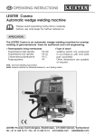
LEISTER Comet
Automatic Wedge Welding Machine
Please read operating instructions carefully before use
and keep for further reference.
APPLICATION
The LEISTER Comet is an automatic wedge welding machine for overlap welding
and manufacturing of films and geomembrane liners in tunnels as well as in
earthwork and civil engineering
Length of Wedge
Note:
For welding materials of 70 mm / 2,8 inch
PVC a special wedge
must be used.
50 mm / 2 inch
20 mm / 0,8 inch
Type of Material
Material Thickness
PE - HD, PP,
PE - LD, …
1,5 – 2,0 mm / 60 – 80 mil
2,0 – 3,0 mm / 80 – 120 mil
PE - HD, PP,
PE - LD, …
0,5 – 1,5 mm / 20 – 60 mil
1,0 – 2,0 mm / 40 – 80 mil
PE - HD, PVC-P,
PE - LD, …
0,5 – 1,0 mm / 20 – 40 mil
• Overlap
max. 125 mm / 5 inch
• Type of seam
Welding seams are produced in accordance with
DVS 2225 part I and BAM. Other dimensions are possible
on request
DVS: German Welding Association
BAM: Federal Institute for Materials Research and Testing, Berlin.
LEISTER
SALES
& SERVICE
CENTER CHINA
, 20H Building No.1
515 Yishan
Road/,Shanghai,
PRC
LEISTER
Process
Technologies,
Riedstrasse,
CH-6060
Sarnen
Switzerland
Tel. +86 021 34141786 Fax. +86 021 64360767
Tel. + 41- 41- 662 74 74 Fax E-mail:
+ 41- 41662 74 16 www.leister.com [email protected]
http://www.plasticwelding.cn
[email protected]
WARNING
Danger ! Unplug the tool before opening it as live components and connections are exposed.
Incorrect use of the hot wedge tool can present a fire
and explosion hazard especially near combustible
materials and explosive gases.
Do not touch the element housing and hot wedge
when hot as they can cause burns. Allow the tool to
cool down. Do not point the hot air flow in the direction
of people or animals.
Connect the tool to a socket outlet with protective
earth conductor. Any interruption of the protective
earth conductor within or outside the tool is dangerous! Use only extensions cables with a protective
earth conductor!
CAUTION
120
230
FI
The voltage rating stated on the tool should correspond
to the mains voltage.
For personal protection, we strongly recommend the
tool be connected to an RCCB (Residual Current Circuit
Breaker) before using it on construction sites.
The tool must be operated under supervision.
Radiant heat from the hot wedge can ignite flammable
materials.
Protect the tool from damp and wet.
APPROVAL MARKS
Protection class Ι
TECHNICAL DATA
70 mm
Length of wedge
Voltage
Power consumption
Frequency
Temperature
Welding pressure
Drive
Size LxBxH
Weight
2
V~
W
Hz
°C/°F
N/lbs pound)
m/min. /feet
mm
kg
50 mm
20 mm
120, 230 ★ 120, 230 ★ 120, 230 ★
1500
1200
700
50 / 60
max. 420 / 790 stepless
max. 1000 / 225 stepless
0,8 – 3,2 / 2,6 – 10,5 stepless
285 x 230 x 230
7, 0 (15,5 lbs)
★ mains voltage cannot be switched over
DESCRIPTION OF FUNCTIONS
LEISTER Comet
• Heating system → The hot air temperature is steplessly adjustable and electronically controlled. According to the material thickness the hot wedge position
can be steplessly adjusted as required.
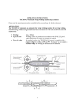
Cross-sectional diagram of hot wedge system
Pinch roller
Upper geomembrane liner
Upper drive /
pressure roller
Welding direction
Adjustment screw
hot wedge
HOT WEDGE
Lower dirve/
pressure roller
Lower geomembrane liner
Rear guide roller
Front guide roller
• Welding Pressure → steplessly adjustable. The welding pressure is transmitted
via a toggle lever to the pressure rollers. The swivel head guarantees the
equalisation of the pressure to both welded sections (C and D) as well as on a
welded seam without test channel.
This allows T-joints to be welded easily. During the welding process the pressure adjusts itself linearly to the change in material thickness of the geomembrane liner.
Cross sectional diagram of an overlap weld
Seam thickness reduction = A – B
A:
B :
C:
D:
E :
Thickness of the upper and lower membrane
Thickness of the welded seam
C
Welded section 1
Welded section 2
B
Test channel
D
B
A
E
• Drive → Double drive system, is steplessly adjustable and electronically controlled. The automatic control system with tachogenerator is designed in such
a way, that the adjusted welding speed remains constant independently of
the load. The power transmission to the drive/pressure rollers works through a
three stage planetary gear.
3
Description of tool
LEISTER Comet
5
Frontal view
4
2
6
1
M
3
27
14
13
15
Back view
9
26
16
12
10
11
25
21
24
22
23
17
8
4
21
18 7
20
DESCRIPTION OF TOOL
1. Cord to mains
2. Housing for drive motor
and electronics
3. Main switch
4. Keyboard
5. Display
6. Drive/power transmission
7. Hot wedge
8. Handle for hot wedge support
9. Lever for welding pressure
10. Adjustment screw for welding
pressure
11. Locking screw
12. Lever locking mechanism
13. Guide handle
LEISTER Comet
14. Travelling wheel
15. Deflector
16. Tube to hot wedge
17. Pinch roller
18. Front guide roller
19. Rear guide roller
20. Lower drive/pressure roller
21. Upper drive/pressure roller
22. Chain
23. Lower part of chassis
24. Adjustment screw, swivel head
25. Lower part of chain guard
26. Cap screw for front guide roller
27. Adjustment screw, hot wedge
WELDING PARAMETERS
12
LEISTER Comet
11 10
– Welding Pressure
Engage and position the automatic welding
machine onto the material to be welded. Pull the
lever for welding pressure (9) without engaging
the hot wedge. By rotating the adjustment screw
for welding pressure (10) the drive/pressure rollers
(20/21) should lightly touch the material to be welded. Unlock the lever for the locking mechanism
(12) and release the tension of the lever (9) at the
same time.
lb
[N]
Illustration A
Welding
pressure
(pound)
Following illustration A,
rotate the adjustment
1000
220
screw (10). Tighten the
900
202
locking screw (11) by
800
179
hand.
700
157
21
134
112
90
67
45
23
600
500
400
300
200
100
4 5
1 2 3 4 5 6 1 2 3 4
Screen
Warning:
If the maximum welding
pressure of 1000 N is
exceeded mechanical
damage may occur.
max. welding pressure 1000 N
5
WELDING PARAMETERS
LEISTER Comet
Welding temperature
+ keys. The temperature is
Set the welding temperature with the H , –
dependent on the material and the ambient temperature. The in-put SET value
will be shown on the display. Switch on the heating by pressing the H and
+ keys simultaneously. Heating up time approx. 5 mins.
Heating
cursor will blink on
the display
H
–
H
&
+
+
SET value setting
ON/OFF
Welding Speed
According on the film or geomembrane liner and the influence of the weather, set the welding speed with the – + keys. The in-put SET value will be
shown to the display.
Drive
–
+
M
SET value adjustment
ON/OFF
WELDING
Welding Preparation
– Laying
– Mains supply
– Cable to mains
LEISTER Comet
Width of overlap 80 mm to 125 mm
Geomembrane liners must be clean between
the overlap as well as above and below.
at least 4kW (generator)
supplied with an RCCB
a minimum cable cross section in accordance
with the table.
230 V~
to 50 m
to 100 m
120 V~
to 50 m
to 100 m
Operating conditions
• Attach guide handle (13).
• Pull out handle (8) and pull
3 x1,5 mm2 / 3 x14 AWG
3 x2,5 mm2 / 3 x12 AWG
3 x1,5 mm2 / 3 x14 AWG
3 x2,5 mm2 / 3 x12 AWG
back the hot wedge support by the handle (8) until it locks again.
• Connect tool to the mains.
• Start the tool with Main or Control Level.
6
WELDING
LEISTER Comet
Version:
Memory card
Standard
1
3
1
3
5
2
4
2
4
6
1
3
5
Main – Level
main switch (3) ON
1
3
Control – Level
–
&
+
&
?
main switch (3) ON
2
Check the welding process
and identify faults by means
of the display of power
consumption.
4
2
Display no.
*
Heating / Drive active
Main
1. Welding speed
2. Welding speed
Not inserted
Inserted
Protocol on
Autostart
SET value
4. Temperature
No / Yes
(none)
No
Yes
No /Yes
?
I
→
Power consumption
ACTUAL value
SET value
5. Welding pressure
No.7
Control
ACTUAL value
6. Memory card
Memory card
7 6
Level
Drive/heating
3. Temperature
< Overload Indication
4
Power consumption
ACTUAL value
Residual capacity
Residual capacity Led green
Led red
(Pos.7)
0
Off
Off
365*
On
Off
364*
On
flashing
Display (4)
Heating reason for fault
100 %
100 %
• mains under-voltage
• heating cartridges faulty
Display (2)
Drive reason for fault
100 %
100 %
100 %
100 %
100 %
• mains under-voltage
• overlap of the geomembrane liner too wide
• dirt on the drive rollers (20/21)
• max. welding pressure (1000 N) has been exceeded.
• high welding speed with large sudden overload
(ie anchoring trench, T-joints....)
<
or <
or <
or <
or
after heating up time
If malfunction is still present, contact service centre.
7
WELDING
LEISTER Comet
Welding procedure
• Check:
– Drive Pressure rollers (20/21) as well as the hot wedge (7) must be
clean before engaging into the geomembrane liner or film.
– Cable length/cable guide
• Guide and position the automatic welding machine into the over-lapped
geomembrane liner or film.
• Adjust welding parameters, see page 5/6.
• The welding temperature must be achieved.
• Switch on drive motor with M key on keyboard (4).
• Engage the hot wedge (7).
• Pull the lever (9).
Beginning of welding process
• Check the welded seam (wash/seam thickness reduction). As required,
+ keys on keyboard (4).
adjust the welding speed with –
• The automatic welding machine is guided along the overlap with the
guide handle (13), so that the frontal width of the overlap is kept within the
20 mm / 0,8 inch zone (see illustration B).
Illustration B
23
25
27
Max. frontal
width of overlap.
20 mm
0,8 inch
End of welding process
• 1 cm before the end of the welded seam release the tension lever (9) and
pull the hot wedge (7) out of the overlap and lift up.
• Switch off the drive motor with M key on the keyboard (4). Switch off the
heating by pressing the H and + keys on the keyboard (4) simultaneously.
8
ADJUSTING THE HOT WEDGE
LEISTER Comet
The hot wedge can be adjusted according to the material thickness as
required.
• Engage the automatic wedge welding machine onto the geomembrane
liner or film to be welded.
• Engage the hot wedge (7).
• Set the tension lever (9) to the specified welding pressure.
• Remove the lower part of the gear housing (25).
• Loosen the cap screw (26).
• Loosen the hexagon cap screw of the rear guide roller (19).
• Adjust the rear guide roller (19) to the correct height. The distance between
the hot wedge (7) and the rear guide roller (19) should be the thickness of
the material.
• Tighten the hexagon cap screw of the rear guide roller (19).
• Loosen the adjustment screw for the hot wedge (27). The hot wedge (7) will
automatically align itself with the geomembrane liner.
• Tighten the adjustment screw for the hot wedge (27).
• Adjust the front guide roller (18) to the correct height. The distance between
the inserted material and the front guide roller (18) should be ca.<1 mm.
• Tighten the hexagon cap screw (26). While doing so the front guide roller (18)
must be held with a hexagon cap screw.
• Assemble chain guard lower part (25).
• Test weld.
9
26
25
21
7
27
18
19
9
Changeover of upper drive/pressure roller
LEISTER Comet
For various applications, for example tunnel construction or civil engineering
at or below ground level, various overlap-welded seams can be manufactured with the LEISTER Comet. These differ in the width of the welded seam
and the width of the test channel. Also welded seams without a test channel
can be manufactured. In order to implement these different overlapped
seams, the appropriate drive/pressure rollers must be fixed. These drive/pressure rollers can be produced in aluminium or stainless steel according to the
customer’s requirements.
1
2
9
8
7
6
5
3
3
4
1. Countersunk screw M3x6
6. Spacer ring
2. Guard plate for swivelling head
7. Drive/pressure roller
3. Set screw M4x8
8. Woodruff key
4. Straight pin 6x80
9. Drive shaft, upper complete
5. Locking ring (shaft Ø 15)
Dismantling of the drive pressure rollers, sequence 1 – 9
Assembly of the drive/pressure rollers, reverse order 9 – 1
10
Changeover of lower drive/pressure roller
LEISTER Comet
2
3
4
5
6
7
8
9
16
15
14
13
12
1
11
10
1. Countersunk screw M3x6
9. Spacer bush
2. Cylinder screw M8x40
10. Guide roller
3. Spacer bush
11. Guard plate drive/pressure roller
4. Nilos-ring Ø 8/20x1,8
12. Countersunk screw M4x12
5. Shim Ø 8/14x0,1
13. Locking washer
6. Rear travelling wheel complete 14. Drive/pressure roller
7. Shim Ø 8/14x0,1
15. Spacer Ø 15/22x0,3
8. Nilos-ring Ø 8/20x1,8
16. Woodruff key 5x6,5
Dismantling of the drive/pressure rollers, sequence 1 – 16
Assembly of the drive/pressure rollers, reverse 16 – 1
11
®
BA Comet/ 06.2001/GB
TRAINING
• LEISTER Process Technologies and their authorised Service Centres offer free
welding courses and training.
ACCESSORIES
• Only LEISTER accessories should be used.
MAINTENANCE
• Clean the hot wedge (7) with a wire brush.
• Clean the drive and pressure roller (20/21) with a wire brush.
• Treat the chain (22) with a suitable spray as required.
• Check mains cable (1) and plug for electrical and mechanical damage.
SERVICE AND REPAIR
• The tool should be checked after a maximum of approx. 1000 hours running
time by an authorised Service Centre
• Repairs have to be carried out by authorised LEISTER Service Centres only. They
guarantee a specialized and reliable repair service within 24 hours using original
LEISTER spare parts.
GUARANTEE AND LIABILITY
• Guarantee and liability are in accordance with the guarantee certificate as well
as with the currently valid general business and sales conditions.
• LEISTER Process Technologies rejects any guarantee claims for tools which are not
in their original condition. The tools must never be altered or changed.
Technical data and specifications are subject to change without prior notice.
Your authorized Service Centre is:
LEISTER
SALES
& SERVICE
CENTER CHINA
, 20H Building No.1
515 Yishan
Road/,Shanghai,
PRC
LEISTER
Process
Technologies,
Riedstrasse,
CH-6060
Sarnen
Switzerland
Tel. +86 021 34141786 Fax. +86 021 64360767
Tel. + 41- 41- 662 74 74 Fax E-mail:
+ 41- 41662 74 16 www.leister.com [email protected]
http://www.plasticwelding.cn
[email protected]