1
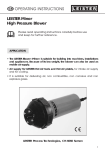
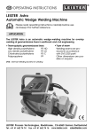
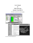
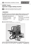
®
GB
OPERATING INSTRUCTIONS
LEISTER Varimat V
Hot Air Automatic Welding Machine
Please read operating instructions carefully before
use and keep for further reference.
APPLICATION
LEISTER Varimat V
Automatic Overlap Welding
Machine
• For overlap welding of roofing
membranes made of PVC, PE,
ECB, EPDM, CSPE, and Modified
Bitumen for areas close to
edges and uneven surfaces.
• Overlap welding of foils and
coated materials. Width of welding seam 20, 40 mm.
LEISTER Varimat V
Automatic Bitumen Welding
Machine
For overlap welding of Modified
Bitumen sheet. Width of welding
seam 80, 100 or 120 mm.
LEISTER Process Technologies, Riedstrasse, CH-6060 Sarnen / Switzerland
Tel. + 41 41 662 74 74 Fax + 41 41 662 74 16 www.leister.com
[email protected]
1
WARNING
Danger! Unplug the tool before opening it as live components and connections are exposed.
Incorrect use of the hot air tool can present a fire and
explosion hazard especially near combustable materials and explosive gases.
Do not touch the element housing and nozzle when hot
as they can cause burns. Allow the tool to cool down.
Do not point the hot air flow at people or animals.
Connect tool to a receptacle with protective earth
terminal. Any interruption of the protective conductor
inside or outside the tool is dangerous !
Line/mains extension cables must always have a protective ground conductor !
CAUTION
230
400
FI
The voltage rating stated on the tool should correspond
to the mains voltage.
For personal protection, we strongly recommend the
tool be connected to an RCCB (Residual Current Circuit
Breaker) before using it on construction sites.
The tool must be operated under supervision. The heat
can ignite flammable materials which are not in view.
Protect the tool from damp and wet.
APPROVAL MARKS
Protection Class Ι
Technical Data
Voltage
Power consumption
Frequency
Temperature
Drive
Welding pressure
Air flow
Emission level
Size
Weight
2
V~
W
Hz
°C
m/min.
N
%
L pA (dB)
mm
kg
230, 400 230, 400 4600, 5700
4600, 6300
50 / 60
50 / 60
20 – 620 stepless
20 – 620 stepless
0,5 – 5 stepless
0,5 – 5 stepless
ca. 190 (2 weights)
ca. 220 (2 weights)
50 – 100
50 – 100
67
67
640 x 430 x 330
640 x 430 x 330
33 with 5 m cable
35 with 5 m cable
Mains voltage cannot be switched over
DESCRIPTION OF TOOLS
LEISTER Varimat V
24 22
23
2
5
27
4
28
29
26
13
12
3
12
15
1
30
8
14
31
16
9
25
20
18
32 7 6
9
10
11
19
12
21
17
1. Cable to mains
2. Housing
3. Main switch
4. Key board
5. Display
6. Sensor
7. Locking screw
8. Hot air blower
9. Welding nozzle
10. Tool holder
11. Locking lever
12. Pendulum action roller
13. Adjustment screw for tracking
14. Track-alignment roller
15. Guide roller
16. Adjustable transport roller
17. Transport roller
18. Guide roller
19. Shift spring for transport roller
20. Gate
21. Scale for tool adjustment
22. Additional weight
23.
24.
25.
26.
27.
28.
29.
30.
31.
32.
End weight
Carrying handle
Socket head cap screw
Lower guide bar
Upper guide bar
Clamping lever guide bar
heigh adujstable
Cable holder
Round belt
Clamping lever guide bar
Sensor covering
12 Pendulum action roller
1 2
3
4
1. Retaining ring
2. Tension ring
3. Rubber buffer
4. Tappet casing
5. Rubber tyre
5
6
7
8
9
6. Rubber buffer
7. Tension ring
8. Tightening disk
9. Cylinder screw
3
DISPLAY OPTIONS
LEISTER Varimat V
1
3
5
2
4
6
1
3
5
2
4
6
Main– Level
main switch (3) on
Display of:
1. Welding speed ACTUAL value
2. Welding speed SET value
3. Temperature ACTUAL value
4. Temperature SET value
5. Voltage - ACTUAL value
6. Welded length - ACTUAL value
Control– Level
–
&
+
&
main switch (3) on
Display of:
1. Welding speed
2. Welding speed
3. Temperature
4. Temperature
5. Voltage
6. Welded length
ACTUAL value
Power consumption in % after start
ACTUAL value
Power consumption in % after start
ACTUAL value
ACTUAL value
*
Heating / Drive active
Display 2
Heating reason for fault
Action
100 %
100 %
• mains under-voltage
• heating element faulty
reduction of airflow
repair
Display 4
Drive reason for fault
Action
100 %
• mains under-voltage
reduction of
welding speed
check welding
procedure/machine
SET value
not achieved
• high welding speed with
large sudden overload
4
FAULT FINDING ACTIONS
LEISTER Varimat V
Automatic starter reason for fault
Drive motor does not start automatically after the nozzle has been positioned
• Sensor (6) set incorrectly
Action adjust Sensor
–
–
–
–
–
–
Switch off main switch (3)
Remove sensor covering (32)
Lower the hot air blower (8) and guide it to the left until it locks
Locking lever (11) must click in
Loosen locking screw for sensor (7)
Push sensor (6) to tool holder (10)
IMPORTANT! Distance between tool holder and sensor > 0,2 – 0,5 mm max.
– Tighten locking screw for sensor (7)
– Fix sensor covering (32)
– Move the hot air blower (8) out until it locks and swivel up
– Make a functional test
If malfunction is still present, contact your Service Center.
3
8
12
10
32
7
6
11
Error 100/ 101/ 102
Measures
check the blower
• Check blower (air must be flowing out of nozzle)
• If malfunction is still present, contact your Service Center
5
WELDING PARAMETERS
LEISTER Varimat V
Welding Temperature
Set the welding temperature with the H , – + keys. The temperature is
dependent on the material and the ambient temperature. The in-put SET value
will be shown on the display. Switch on the heating by pressing the + and
H keys simultaneously. Heating-up time approx. 5 mins. (SET value not achieved, see airflow).
Heating
Cursor will blink
on the display
H
–
+
Airflow
&
+
SET value setting
ON / OFF
H
H
2x
–
+
Important note:
During the heating-up process, the airflow is adjusted automatically
to 100%. Only after reaching the SET temperature, the pre-set airflow
in %, is taken over (element protection). If the SET temperature has
not been achieved, adjust the airflow to 80% before switching on the
heating element.
Reset
Welded length
M
&
+
Welding speed
Depending on the film or geomembrane liner and the influence of the weather,
set the welding speed with the – + keys. The in-put SET value will be shown
on the display.
Drive
–
M
6
+
SET value setting
ON / OFF
WELDING PARAMETERS
Overlap 20/40 mm
Welding pressure
• The welding pressure is transmitted to the
pendulum action roller (12).
• As necessary, the additional weights (22) and
the end weight (23) can be put on
(see illustration H).
LEISTER Varimat V
Illustration H
120 N
155 N
190 N
22
23
2
12
OPERATION
Overlap 20/40 mm
LEISTER Varimat V
Operating condition
•
•
•
•
Attach strain relief of guide bar (26/27)
Hang the mains cable (1) into the cable holder (29).
Adjust the guide bar (27) with the clamping lever (28) to the desired height
.Check the basic setting of the welding nozzle (9).
(ex works illustration A and C)
• Transport setting:
– Swivel the guide roller (18) upwards
– Release the transport roller (16) by raising the guide bar (27).
– Push the transport roller (16) by applying a little pressure to the shift spring (19)
to the left until it stops (illustration B).
– Position the hot air blower (8) by pulling the locking lever (11) and swivel it up
until it locks.
Illustration A
• Connect the tool to the mains
The voltage rating stated on the tool should
correspond to the mains voltage.
1 – 2 mm
40
–
Illustration
18
B
16 19
Illustration
C
9
50
m
m
2
1–
mm
12
7
USAGE
Overlap 20/40 mm
LEISTER Varimat V
Tool positioning
• Tip up the Automatic Welding Machine by applying pressure to the guide bar
(27) and position it ready for welding.
• Release the transport roller (16) by lifting it with the guide bar (27).
• Push the transport roller (16) to the left until it stops by applying light pressure
to the shift spring (19).
• Swivel the guide roller (18) down.
• The guide roller (18) should be set parallel to the edge of the pendulum
action roller (12) (see illustration E)
• Do a test run
• To correct the tracking , adjust the adjustment screw for tracking (13) (see illustration F and G, and the function notes on the automatic welding machine).
Illustration E
Illustration F
Illustration G
18
12
12
13
12
13
Welding procedure
•
•
•
•
•
•
•
•
8
Adjust welding parameter, see page 6.
The welding temperature must be achieved (heating up time approx. 5 min).
Do a test run.
Pull the locking lever (11), lower the hot air blower (8) and position it between
the overlapped sheets until it stops.
If it does not start, see sensor adjustment, page 5.
The machine can be started manually with key M
The automatic welding machine is guided along the overlap with the guide
bar (27). Do not apply pressure to the guide bar (27) this could lead to
welding faults. Keep watching the guide roller (18) position.
After welding, pull the locking lever (11), take the hot air blower (8) out
until it stops and swivel up until it locks.
After completion of the welding work switch off the heater by pressing keys
+ and H on keyboard (4) simultaneously, so that the welding nozzle (8)
cools down.
Switch off main switch (3).
WELDING PARAMETERS
Overlap 80/100/120 mm
Welding pressure
• The welding pressure is transmitted to the
pendulum action roller (12).
• As necessary, the additional weights (22)
and the end weight (23) can be put on
(see illustration H).
LEISTER Varimat V
Illustration H
140 N
175 N
210 N
22
23
2
12
OPERATION
Overlap 80/100/120 mm
LEISTER Varimat V
Operating condition
•
•
•
•
•
Attach the guide bar (26/27).
Hang strain relief of mains cable (1) in the cable holder (29).
Adjust the guide bar (27) with the clamping lever (28) to the desired height
Check the basic setting of the welding nozzle (9). (ex works detail A and C).
Transport setting:
– Swivel the guide roller (18) upwards.
– Release the transport roller (16) by lifting up with the guide bar (27).
– Push the transport roller (16) by applying a little pressure to the shift spring (19)
to the left until it stops (illustration B).
– Position the hot air blower (8) by pulling the locking lever (11) and swivel it up
until it locks.
Illustration A
• The basic adjustment of the welding nozzle (9)
is done at the factory (Illustration A and C)
• Connect the tool to the mains.
The voltage rating stated on the tool should
correspond to the mains voltage.
1 – 2 mm
70
–
Illustration
18
B
16 19
Illustration
C
9
85
m
m
2
1–
mm
12
9
Overlap 80/100/120 mm
USAGE
LEISTER Varimat V
Tool positioning
• Tip up the Automatic Welding Machine by applying pressure to the guide bar
(27) and position it ready for welding.
• Release the transport roller (16) by lifting it with the guide bar (27).
• Push the transport roller (16) to the left until it stops by applying light pressure
to the shift spring (19).
• Swivel the guide roller (18) down.
• The guide roller (18) should be set parallel to the edge of the pendulum
action roller (12) (see illustration E).
• Do a test run
• To correct the tracking, adjust the adjustment screw for tracking (13) (see
illustration F and G, and the function notes on the automatic welding
machine).
Illustration F
Illustration E
Illustration G
18
12
12
13
12
13
Welding procedure
• Adjust welding parameters, see page 6.
• The welding temperature must be achieved (heating up time approx. 5 min.).
If the temperature is not achieved, reduce the airflow.
• Do a test run.
• Pull the locking lever (11), lower the hot air blower (8) and position it between
the overlapped sheets until it stops. The drive motor will start automatically.
If it does not start, see sensor adjustment, page 5.
The machine can be started manually by pressing key M .
• The automatic welding machine is guided along the overlap with the guide
bar (27). Do not apply pressure to the guide bar (27) this could lead to welding
faults. Keep watching the guide roller (18) position.
• After welding, pull the locking lever (11), take the hot air blower (8) out until it
stops and swivel up until it locks.
• When the welding is completed switch off heater with the + and H keys
on the keyboard (4), so that the welding nozzle (8) cools down.
• Switch off main switch (3).
10
®
BA Varimat V /09.2003
ACCESSORIES
• Only LEISTER accessories should be used.
TRAINING
LEISTER and its authorized Service Centres offer welding courses world-wide
free of charge. If necessary, customers will also receive training on site.
MAINTENANCE
• Clean the welding nozzle (9) with a wire brush.
• Clean air inlet to blower (8).
• Check mains cable (1) and plug for electrical and mechanical damage.
SERVICE AND REPAIR
• If display shows the message «maintenance; servicing» the machine must be
examined by an authorised LEISTER service centre.
• Repairs have to be carried out by authorised LEISTER Service Centres only. They
guarantee a specialized and reliable repair service within 24 hours using original LEISTER spare parts.
GUARANTEE AND LIABILITY
• Guarantee and liability are in accordance with the guarantee certificate as
well as with the currently valid general business and sales conditions.
• LEISTER Process Technologies rejects any guarantee claims for tools which are
not in their original condition. The tools must never be altered or changed.
Technical data and specifications are subject to change without prior notice.
Your authorised Service Centre is:
LEISTER Process Technologies, Riedstrasse, CH-6060 Sarnen / Switzerland
Tel. + 41 41 662 74 74 Fax + 41 41 662 74 16 www.leister.com
[email protected]
11
®
Service Record LEISTER Varimat V
This document should be kept up to date during repair or servicing by the
authorized LEISTER Service Centre. This document should be in the possession
of the owner of the equipment.
Technical data
Type of Automatic Hot Air Welding Machine
Order No.
Serial No
Rated voltage
V
Rated capacity
W
Sale
date
Service
1. Date
Service Centre
Signature
2. Date
Service Centre
Signature
3. Date
Service Centre
Signature
4. Date
Service Centre
Signature
5. Date
Service Centre
Signature
6. Date
Service Centre
Signature
1. Date
Service Centre
Signature
2. Date
Service Centre
Signature
3. Date
Service Centre
Signature
Repair
LEISTER Process Technologies, Riedstrasse, CH-6060 Sarnen / Switzerland
Tel. + 41 41 662 74 74 Fax + 41 41 662 74 16 www.leister.com
[email protected]
12