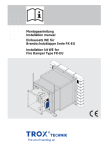
Download Operating and Installation Manual Fire damper type FKR-EU
Transcript
FKR-EU/DE/DE/en Operating and Installation Manual Fire damper type FKR-EU according to Declaration of Performance DoP / FKR-EU / DE / 2013 / 001 Contents 1 General information______________________ 3 Scope of this manual ___________________________3 Other applicable documentation __________________3 Symbols used in this manual _____________________3 Rating plate with CE marking_____________________3 2 Safety and correct use ___________________ 4 General information regarding safety ______________4 Standards and guidelines _______________________4 Repair and replacement parts ____________________4 Environmental protection ________________________4 Correct use __________________________________4 Residual risks ________________________________4 3 Product description ______________________ 5 Functional description ________________________5 Product overview, dimensions, and weights______6 Construction variant with spigots__________________6 Flange construction ____________________________7 4 Technical data __________________________ 8 5 Transport, storage, and packaging _________ 8 Delivery check ________________________________8 Transport on site ______________________________8 Storage _____________________________________8 Packaging ___________________________________8 6 Installation _____________________________ 9 General installation information ________________9 Acceptable mortars for mortar-based installation _____9 Acceptable mineral wool as filling material __________9 Overview of installation situations and fire resistance class according to 13501-3 ______________________9 Solid walls _________________________________10 Solid ceiling slabs ___________________________ 11 Lightweight partition walls with metal support structure and cladding on both sides __________12 Nominal size ØDN 315 to 400 ___________________ 12 Nominal size ØDN 450 to 800 ___________________ 13 Lightweight partition walls with metal support structure and cladding on one side ____________14 Nominal size ØDN 315 to 400 ___________________ 14 Nominal size ØDN 450 to 800 ___________________ 15 Lightweight partition walls without metal support structure and cladding on one side (shaft walls) _16 Nominal size ØDN 315 to 400 ___________________ 16 Nominal size ØDN 450 to 800 ___________________ 17 Fire walls with metal support structure and cladding on both sides ___________________18 Nominal size ØDN 315 to 400 ___________________ 18 Nominal size ØDN 450 to 800 ___________________ 19 Metal support structure for fire walls - details _______20 7 Connecting the duct ____________________ 21 Removing the transport/installation protection ______21 Flexible connectors ___________________________21 Cover grille _________________________________22 Inspection access ____________________________22 8 Electrical connection ___________________ 23 Equipotential bonding _________________________23 Limit switches for FKR-EU with fusible link _________23 AS-i/LON modules ____________________________23 9 Functional test _________________________ 24 General information ___________________________24 FKR-EU with fusible link _______________________24 FKR-EU with spring return actuator _______________25 Opening the damper blade using the crank handle ___25 10 Commissioning ________________________ 26 Operation ___________________________________26 11 Maintenance ___________________________ 26 Maintenance ________________________________26 Inspection __________________________________26 Repair _____________________________________26 Lubricating points ____________________________27 Replacing the fusible link_____________________28 Inspection, maintenance and repair measures ______30 12 Decommissioning, removal and disposal___ 31 TROX GmbH Heinrich-Trox-Platz 47504 Neukirchen-Vluyn, Germany Phone +49(0)2845 2020 Fax +49(0)2845 202265 E-mail [email protected] www.troxtechnik.com 2 Part no. M375EE3 Subject to change / All rights reserved © TROX GmbH Operating Manual FKR-EU/DE/DE/en (10/2013) 1 General information Scope of this manual This operating and installation manual applies to fire dampers that are installed in Germany. National regulations must be observed. Other applicable documentation In addition to this manual the declaration of performance DoP / FKR-EU / DE / 2013 / 001 applies. Symbols used in this manual Danger! Designates danger to life and limb due to electrical voltage. Warning! Designates danger to life and limb. Important! Designates danger that can cause minor personal injury or damage to property. Note! Designates important notes or information. Rating plate with CE marking ݇ A00000026813_0713 This operating and installation manual describes the following variants of the fire damper: • FKR-EU with fusible link • FKR-EU with spring return actuator To ensure complete functioning of the fire damper it is essential to read the provided operating and installation manual before starting any work, and to comply with it. The manual must be given to the facilities manager when handing over the system. The facilities manager must include the manual with the system documentation. The manufacturer does not accept any liability for any malfunction or damage resulting from non-compliance with this manual or non-compliance with relevant statutory regulations. This operating and installation manual is intended for specialist consultants, developers, and operators of systems in which the fire dampers are to be installed. This manual is also intended for people conducting the following work: • Transport and storage • Installation • Electrical connection • Commissioning • Operation • Maintenance • Decommissioning, removal and disposal ݈ ݉ TROX GmbH Heinrich-Trox-Platz 47504 Neukirchen-Vluyn www.trox.de 12 Jahr/year-13 ݊ DoP / FKR-EU / DE / 2013 / 001 EN 15650: 2010 Brandschutzklappe /fire damper FKR-EU EI TT (ve-ho, i ݍ o) S - (300 Pa) ݎ CE mark Manufacturer's address Number of the European standard and year of its publication The last two digits of the year of the marking Year of manufacture No. of the declaration of performance Regulated characteristics The fire resistance class depends on the application and may vary → P. 9 Type Operating Manual FKR-EU/DE/DE/en (10/2013) 3 2 Safety and correct use General information regarding safety Only skilled, qualified personnel are allowed to perform the described work on the fire damper. Only skilled qualified electricians are allowed to work on the electrical system. The installation location must be easily accessible and have sufficient clearance for electrical connection and maintenance of the fire damper. Standards and guidelines • EN 15650:2010 Ventilation for buildings – fire dampers • Classification to EN 13501-3 → P. 9 • Tested to EN 1366-2 • Closed blade air leakage to EN 1751, class 4 • Casing air leakage according to EN 1751, class C Compliance with all additional related fire protection standards and regulations is required. Repair and replacement parts The FK-EU fire damper is a safety related product that has been especially developed for fire protection. To maintain the function, only original TROX replacement parts must be used. Environmental protection To protect the environment observe the following: • Dispose of packaging in an environmentally sound manner. • Have used fire damper components or the used fire damper only disposed of by an authorised company. • Dispose of electronic components according to the local electronic waste regulations. 4 Correct use The fire damper is used as an automatic shut-off device to prevent fire and smoke from spreading through ducting. The fire damper is suitable for supply air and extract air systems. Use of the fire damper is only allowed in compliance with national fire protection regulations. Operation of the fire damper is allowed only in compliance with installation regulations and the technical data in this operating and installation manual. Incorrect use The following applications are not allowed: • Use as a smoke extract damper. • Use in potentially explosive atmospheres. • Use outdoors without sufficient protection against the effects of weather. • Use in extract air systems in commercial kitchens. • Use in ventilation systems in which high levels of contamination, extreme humidity, or chemical contamination may impair the damper function. • Installation in a way that prevents an inspection of the internal components of the fire damper. Changes to the fire damper and the use of replacement parts that have not been approved by TROX are not permitted. Residual risks TROX fire dampers are subject to strict quality controls during manufacturing. In addition, function tests are performed before delivery. In addition, a functional test is performed before delivery. Damage can, however, occur during transport or installation and impair the function of the fire damper. In any case, the proper function of the fire damper must be checked during commissioning and ensured through regular maintenance while in use. Operating Manual FKR-EU/DE/DE/en (10/2013) 2 Product 3 1 PageHeaderToc description Functional description Functional diagram Damper blade OPEN Damper blade CLOSED in case of a fire Fire-resistant wall Functional description Type FKR-EU fire dampers are used as safety related components in ventilation systems. The fire damper is used to to prevent fire and smoke from spreading through ducting. During operation at normal temperature, the fire damper is open to enable air passage through the ventilation system. If the temperature increases in case of a fire, the damper blade closes. The damper is triggered either by a fusible link at 72 °C (95 °C in the case of warm air ventilation systems) or thermoelectrically with a spring return actuator. If the damper blade closes due to a temperature increase (i.e. in case of a fire), it must not be reopened. The proper functioning of the fire damper can be tested in two ways, depending on the release mechanism. → P. 24 FKR-EU with fusible link If the temperature inside the fire damper rises to 72 °C or 95 °C, respectively, the fusible link triggers a coil spring mechanism which causes the damper blade to close. The coil spring mechanism then causes the fire damper to close. As an option, the FKR-EU with a fusible link can be either supplied or subsequently fitted with one or two limit switches. The limit switches can signal the damper blade position to the central BMS or fire alarm system. One limit switch each is required for damper blade positions OPEN and CLOSED. FKR-EU with spring return actuator The spring return actuator enables the motorised opening and closing of the damper blade; it can be activated by the central BMS. As long as power is supplied to the actuator, the damper blade remains open. In case of a fire, the fire damper is closed by the internal thermoelectric release mechanism when the temperature in the duct rises above 72 °C or 95 °C, respectively, or when the temperature on the actuator of the fire damper rises above 72 °C or when the supply voltage fails (power off to close). As standard, the spring return actuator is equipped with limit switches that can be used to indicate the damper blade position. TROX smoke detector The TROX smoke detector type RM-O-3-D or RM-O-VS-D can be used to trigger closing of the FKR-EU damper blade. This is only possible when the fire damper is equipped with a spring return actuator. Operating Manual FKR-EU/DE/DE/en (10/2013) 5 1 Product 3 1 PageHeaderToc description Product overview, dimensions, and weights Construction variant with spigots FKR-EU with fusible link 550 420 370 50 50 150 70 ØDN ݊ Ⓑ ݉ ݇ ݗ ݖ Ⓐ Operating side ݈ ݏ Installation side Keep clear to provide access to the release mechanism FKR-EU with spring return actuator 550 420 370 50 150 50 ØDN 70 ݎ ݍ Ⓑ ݇ ݗ ݖ Ⓐ Operating side ݈ ݏݎ Installation side Keep clear to provide access to the spring return actuator FKR-EU and FKR-EU-FL Dimensions [mm] Nominal size ØDN A ØD1 α Number of screw holes 6 FKR-EU and FKR-EU-FL Weight [kg] 315 355 400 450 500 560 630 710 800 314 31 352 45° 354 31 392 45° 399 31 438 45° 449 36 488 45° 498 36 538 45° 558 36 600 30° 629 36 670 30° 709 36 750 30° 799 36 840 22.5° 8 8 8 8 8 12 12 12 16 Nominal size 315 355 400 450 500 560 630 710 800 with fusible link 6.8 7.3 8.5 14.1 16.4 18.0 21.3 25.7 28.6 with spring return actuator 8.2 8.7 9.9 16.7 19.0 20.6 23.9 28.3 31.2 Operating Manual FKR-EU/DE/DE/en (10/2013) 3 Product description Product overview, dimensions, and weights Flange construction FKR-EU-FL with fusible link 500 395 345 ǭ Ø1 9,5 A 150 70 ݊ Ⓑ ˣ ØDN ݉ ݇ ݗ Operating side ݏ ݈ Ⓐ Keep clear to provide access to the release mechanism Installation side FKR-EU-FL with spring return actuator 500 395 345 ǭ A 150 ݗ ݇ ݎ ݍ Ⓑ ˣ ØDN Ø1 9,5 70 Operating side ݈ Ⓐ ݎ ݏ Installation side Keep clear to provide access to the spring return actuator Casing Fusible link Damper blade with seal Spring return actuator Handle Thermoelectric release mechanism Release mechanism with cover Travel stop Interlock Lip seal Operating Manual FKR-EU/DE/DE/en (10/2013) Installation marking ØDN ≤ 400: grove; ØDN ≥ 450: indentation Ⓐ Installation side Ⓑ Operating side 7 1 Technical 4 1 PageHeaderToc data 5 Transport, storage, and packaging Limit switch Connecting cable length / cross section Protection level Type of contact Max. switching current Max. switching voltage Contact resistance Spring return actuator BLF Supply voltage Spring compression Hold position Rating Running time Motor / spring return Type of contact Switching voltage Limit switch Switching current Contact resistance IEC protection class Protection level Storage temperature Ambient temperature Ambient humidity Actuator Connecting cable Limit switch Power rating Spring return actuator BF Supply voltage Spring compression Hold position Rating Running time Motor / spring return Type of contact Switching voltage Limit switch Switching current Contact resistance IEC protection class Protection level Storage temperature Ambient temperature Ambient humidity Actuator Connecting cable Limit switch Power rating 1 m / 3 × 0.34 mm² IP 66 1 changeover contact, gold-plated 0.5 A 30 V DC, 250 V AC approx. 30 mΩ 230-T TR 24-T-ST TR 24 V AC ±20 % 50/60 Hz 230 V AC ±14 % or 50/60 Hz 24 V DC -10 % / +20 % 6W 5W 3W 2.5 W 7 VA 40 to 75 s / 20 s 2 change-over contacts 5 – 120 V DC / 5 – 250 V AC 1 mA – 3 A < 100 mΩ II III IP54 −40 ... +50°C −30 ... +50 °C ¹ ≤ 95 % RH, non-condensing 1 m / 2 × 0.75 mm² 1 m / 6 × 0.75 mm² 230-T-2 TR 24-T-ST-2 TR 230 V AC ±14 % 50/60 Hz 24 V AC ±20 % 50/60 Hz or 24 V DC -10 % / +20 % Important! Danger of injury from edges and sheet metal parts. Always wear protective gloves when handling the unit. Delivery check Check delivered items immediately after arrival for transport damage and completeness. In case of any damage or an incomplete shipment, contact the shipping company and your supplier immediately. A complete shipment includes: • Fire damper • Attachments / accessories, if any • Operating manual (1 per shipment) Transport on site If possible, take the fire damper in its transport packaging up to the installation location. Storage If the fire damper has to be stored temporarily: • Remove any plastic wrapping. • Store the fire damper in a clean place, away from dust and pollution. • Store the unit in a dry place and away from direct sunlight. • Do not expose the fire damper (not even with its packaging) to the effects of weather. • Do not store the fire damper below -40 °C or above 50 °C. Packaging Properly dispose of packaging material. 8W 7W 3W 2W 12.5 VA 10 VA approx. 140 s / approx. 16 s 2 change-over contacts 5 – 120 V DC / 5 – 250 V AC 1 mA – 6 A < 100 mΩ II III IP54 −40 ... +50°C −30 ... +50 °C ¹ ≤ 95 % RH, non-condensing 1 m / 2 × 0.75 mm² 1 m / 6 × 0.75 mm² ¹ Up to 75 °C the safe position will definitely be reached. 8 Operating Manual FKR-EU/DE/DE/en (10/2013) 2 Installation 6 1 PageHeaderToc General installation information Important! Danger of injury from edges and sheet metal parts. Always wear protective gloves when handling the unit. Wall installation Horizontal installation The fire damper can be installed in any orientation. Minimum wall and ceiling slab thicknesses. → See table below. Please note: • Operating components and the electric actuator must remain accessible for inspection and maintenance work. • If the thickness of the wall or ceiling slab exceeds 115 mm, an extension piece (accessory or provided by others) is required to connect the fire damper to the duct. • Perform a functional test before installation. → P. 24 • Do not remove the transport and installation safety device until the mortar/concrete has hardened. Acceptable mortars for mortar-based installation In case of mortar-based installation, the open spaces between the fire damper and the wall or ceiling slab must be closed off with mortar. Entrapped air is to be avoided. The mortar bed depth must be at least 100 mm. The following mortars are acceptable: • DIN 1053: Groups II, IIa, III, IIIa; fire protection mortar of groups II, III • EN 998-2: Classes M 2.5 to M 10, or fire protection mortar of classes M 2.5 and M 10 • Equivalent mortars that meet the requirements of the above standards • Gypsum mortar or concrete Acceptable mineral wool as filling material Mineral wool with gross density ≥ 80 kg/m³, melting point ≥ 1000 °C. Vertical installation Ceiling installation Upright installation Suspended installation x = see corresponding installation details Note! The fire resistance classes of the fire damper and the wall/celing slab may differ from each other. The final fire resistance class of the total system, however, is determined by the lower fire resistance class. Overview of installation situations and fire resistance class according to 13501-3 Installation location Construction and building material Minimum thickness [mm] Class of performance EI TT (ve–ho, i ↔ o) S Installation details on page Solid walls Solid walls, gross density ≥ 500 kg/m³ 100 EI 120 S 10 Solid ceiling slabs Solid ceiling slabs, gross density ≥ 600 kg/m³ 150 EI 120 S 11 Lightweight partition walls with metal support structure and cladding on both sides Lightweight partition walls 100 EI 90 S 12 Fire walls with metal support structure and cladding on both sides Fire walls 115 EI 90 S 18 Lightweight partition walls with metal support structure and cladding on one side Shaft walls 90 EI 90 S 13 Lightweight partition walls without metal support structure and cladding on one side Shaft walls 50 EI 90 S 16 Operating Manual FKR-EU/DE/DE/en (10/2013) 9 1 Installation 6 1 PageHeaderToc Solid walls Mortar-based installation For mortar-based installation of fire dampers in solid walls the fire damper is concreted into the wall during construction or alternatively installed after construction with a perimeter mortar bed. Requirements • Solid walls or fire walls (if referred to as such) made of, for example, concrete, aerated concrete, masonry, or solid gypsum wallboards according to EN 12859 (without hollow spaces), gross density ≥ 500 kg/m³, and a minimum thickness of 100 mm • 40 mm minimum distance to load bearing structural elements. • 40 mm minimum distance between two fire dampers, about 80 mm with flanged construction W̟ ࿆ ݢ ࿇ W̟ 115 z Installation after completing the wall To install the fire damper into a completed wall, proceed as follows: • Create an appropriate opening or cut hole: Ø opening = nominal size of the fire damper + at least 80 mm • Push the fire damper into the installation opening and secure it. Also observe distance dimension z. → Table. • If the wall thickness is > 115 mm, extend the fire damper with an extension piece or a spiral duct on the installation side. • Close off the perimeter gap »s« with mortar. The mortar bed depth must be at least 100 mm. sุ 40 Installation while erecting the wall If the fire damper is installed as the wall is being erected, the perimeter gap »s« is not required. To install the fire damper, proceed as follows: • Place the fire damper on a bed of mortar in the planned installation position in the wall and secure it. Also observe distance dimension z. → Table. • If the wall thickness is > 115 mm, extend the fire damper with an extension piece or a spiral duct on the installation side. • Brick the fire damper into the wall with a perimeter bed of mortar. ݣ ࿆ ݢ ࿇ ① Mortar → „Acceptable mortars for mortar-based installation“ see Page 9 ② Extension piece Ⓐ Installation side Ⓑ Operating side Distance z [mm] FKR-EU with spigots FKR-EU with flanges 10 sุ 40 z Warning! Contamination or damage will impair the function of the fire damper. • Protect the fire damper from contamination and damage. • Cover the flange openings and release mechanism (e.g. with plastic foil) to protect them from mortar and dripping water. After installation • Clean the fire damper and wash off any residual mortar with water. • The fire damper is provided with a transport and installation safety device. This safety device must not be removed until after the mortar has hardened. → P. 21 • After the hardening of the mortar, perform a functional test of the fire damper. → P. 24 • Connect the ducting. → P. 21 • Establish the electrical connection. → P. 23 100 370 345 Operating Manual FKR-EU/DE/DE/en (10/2013) 2 Installation 6 1 PageHeaderToc Solid ceiling slabs Mortar-based installation Fire dampers are concreted in during the construction of the ceiling or installed using a perimeter mortar-mix after the completion of the ceiling slab. Upright installation ࿇ After installation • Clean the fire damper and wash off any residual mortar with water. • The fire damper is provided with a transport and installation safety device. This safety device must not be removed until after the mortar has hardened. → P. 21 • After the hardening of the mortar, perform a functional test of the fire damper. → P. 24 • Connect the ducting. → P. 21 • Establish the electrical connection. → P. 23 ݣ s̟ ̟ʸʷʷ D ࿆ 40 ̟ʸʼʷ Suspended installation ࿆ ݣ s̟ 40 ݢ D Installation after completing the ceiling slab To install the fire damper into a completed ceiling slab, proceed as follows: • Create an appropriate opening or cut hole: Ø opening = nominal size of the fire damper + at least 80 mm • Push the fire damper into the installation opening and secure it. Also observe distance dimension z. → Table. • Extend the fire damper with an extension piece or a spiral duct on the installation side. • Close off the perimeter gap »s« with mortar. The mortar bed depth must be at least 100 mm. ݢ ࿇ z Installation while completing the ceiling slab If the fire damper is installed as the ceiling slab is being completed, the perimeter gap »s« is not required. • Place the fire damper in the installation location and secure it. Also observe distance dimension z. → Table. • Protect the spigot and the operating components/actuator, e.g. with plastic foil. • Extend the fire damper with an extension piece or a spiral duct on the installation side. • Cast the concrete around the fire damper. z Warning! Contamination or damage will impair the function of the fire damper. • Protect the fire damper from contamination and damage. • Cover the flange openings and release mechanism (e.g. with plastic foil) to protect them from mortar and dripping water. ̟100 Requirements • Solid ceiling slabs made of concrete or aerated concrete, gross density ≥ 600 kg/m³ and D ≥ 150 mm • 40 mm minimum distance to load bearing structural elements. • 40 mm minimum distance between two fire dampers, about 80 mm with flanged construction ̟ʸʼʷ ① Mortar → „Acceptable mortars for mortar-based installation“ see Page 9 ② Extension piece Ⓐ Installation side Ⓑ Operating side Distance z [mm] FKR-EU with spigots FKR-EU with flanges Operating Manual FKR-EU/DE/DE/en (10/2013) 370 345 11 1 Installation 6 1 PageHeaderToc Lightweight partition walls with metal support structure and cladding on both sides Nominal size ØDN 315 to 400 Ø DN + 80 ... 120 Warning! Contamination or damage will impair the function of the fire damper. • Protect the fire damper from contamination and damage. • Cover the flange openings and release mechanism (e.g. with plastic foil) to protect them from mortar and dripping water. After installation • Clean the fire damper and wash off any residual mortar with water. • The fire damper is provided with a transport and installation safety device. This safety device must not be removed until after the mortar has hardened. → P. 21 • After the hardening of the mortar, perform a functional test of the fire damper. → P. 24 • Connect the ducting. → P. 21 • Establish the electrical connection. → P. 23 W̟ z 0 10 ݢ Y ࿆ ݤ ࿇ ݣ Detail Y W ̟ 100 12,5 12,5 ·̟10 ݢ ݣ ݥ ݤ s ̟ 40 To install the fire damper, proceed as follows: • Erect the lightweight partition wall according to the manufacturer's instructions. • Create an installation opening. Provide the installation opening in the metal support structure with support profiles. • Insert trim panels (optional). • Push the fire damper into the wall opening. Also observe distance dimension z. → Table. • If the wall thickness is > 115 mm, extend the fire damper with an extension piece or a spiral duct on the installation side. • Completely close off the perimeter gap »s« with mortar across the complete wall thickness. Profiles with screws or rivets ̞ 625 sุ 40 Requirements • Lightweight partition walls with a metal support structure and cladding on both sides, with European classification to EN 13501-2 or comparable national classification • Cladding made of gypsum bonded or cement bonded panel materials and a minimum wall thickness of W ≥ 100 mm • Additional layers of cladding are approved. • Installation details for special versions, e.g. double stud system, up request. • 40 mm minimum distance to load bearing structural elements. • 40 mm minimum distance between two fire dampers, about 80 mm with flanged construction Metal support structure, nominal size ØDN 315 to 400 Ø DN + 80 ... 120 Mortar-based installation Fire dampers with a perimeter mortar mix are used for mortar-based installation into lightweight partition walls. ① Perimeter metal profile ② Dry wall screw ③ Mortar, preferably gypsum mortar → „Acceptable mortars for mortar-based installation“ see Page 9 Distance z [mm] FKR-EU with spigots FKR-EU with flanges 12 ④ Optional trim panels 370 345 Ⓐ Installation side Ⓑ Operating side Operating Manual FKR-EU/DE/DE/en (10/2013) 6 Installation Lightweight partition walls with metal support structure and cladding on both sides Nominal size ØDN 450 to 800 Metal support structure, nominal size ØDN 450 to 800 Requirements • Lightweight partition walls with a metal support structure and cladding on both sides, with European classification to EN 13501-2 or comparable national classification • Cladding made of gypsum bonded or cement bonded panel materials, wall thickness of W ≥ 100 mm • Additional layers of cladding are approved. • Installation details for special versions, e.g. double stud system, up request. • 40 mm minimum distance to load bearing structural elements. • 40 mm minimum distance between two fire dampers, about 80 mm with flanged construction 45° Ø DN + 80 ... 120 ̞ 625 Warning! Contamination or damage will impair the function of the fire damper. • Protect the fire damper from contamination and damage. • Cover the flange openings and release mechanism (e.g. with plastic foil) to protect them from mortar and dripping water. To install the fire damper, proceed as follows: • Erect the lightweight partition wall according to the manufacturer's instructions. • Create an installation opening. To do so, provide the installation opening in the metal support structure with support profiles. From nominal size 450, reinforce the support structure with four additional profiles installed under 45°. • Insert trim panels (optional). • Push the fire damper into the wall opening. Also observe distance dimension z. → Table. • If the wall thickness is > 115 mm, extend the fire damper with an extension piece or a spiral duct on the installation side. • Completely close off the perimeter gap »s« with mortar across the complete wall thickness. After installation • Clean the fire damper and wash off any residual mortar with water. • The fire damper is provided with a transport and installation safety device. This safety device must not be removed until after the mortar has hardened. → P. 21 • After the hardening of the mortar, perform a functional test of the fire damper. → P. 24 • Connect the ducting. → P. 21 • Establish the electrical connection. → P. 23 Profiles with screws or rivets 0 10 sุ 40 W̟ z ݢ Y ࿆ ݤ ݣ ࿇ Detail Y W ̟ 100 12,5 12,5 ·̟10 ݢ ݣ ݥ ݤ ࿇ s ̟ 40 Mortar-based installation Fire dampers with a perimeter mortar mix are used for mortar-based installation into lightweight partition walls. ࿆ ① Perimeter metal profile ② Dry wall screw ③ Mortar, preferably gypsum mortar → „Acceptable mortars for mortar-based installation“ see Page 9 Distance z [mm] FKR-EU with spigots FKR-EU with flanges ④ Optional trim panels 370 345 Operating Manual FKR-EU/DE/DE/en (10/2013) Ⓐ Installation side Ⓑ Operating side 13 6 Installation Lightweight partition walls with metal support structure and cladding on one side Nominal size ØDN 315 to 400 Ø DN + 80 ... 120 Warning! Contamination or damage will impair the function of the fire damper. • Protect the fire damper from contamination and damage. • Cover the flange openings and release mechanism (e.g. with plastic foil) to protect them from mortar and dripping water. z ݢ Y ࿆ ݤ ࿇ ݥ Detail Y ݣ W ̟ 90 20 40 ·̟10 ݢ ݣ s ̟ 40 After installation • Clean the fire damper and wash off any residual mortar with water. • The fire damper is provided with a transport and installation safety device. This safety device must not be removed until after the mortar has hardened. → P. 21 • After the hardening of the mortar, perform a functional test of the fire damper. → P. 24 • Connect the ducting. → P. 21 • Establish the electrical connection. → P. 23 90 W̟ 60 To install the fire damper, proceed as follows: • Erect the lightweight partition wall according to the manufacturer's instructions. • Create an installation opening. Provide the installation opening in the metal support structure with support profiles. • Create reinforcing board. • Push the fire damper into the wall opening. Also observe distance dimension z. → Table. • If the wall thickness is > 115 mm, extend the fire damper with an extension piece or a spiral duct on the installation side. • Completely close off the perimeter gap s« with mortar across the complete wall thickness. Profiles with screws or rivets ̞ 625 sุ 40 Requirements • Lightweight partition walls with a metal support structure and cladding on one side with European classification according to EN 13501-2 or comparable national classification • Cladding made of gypsum bonded or cement bonded panel materials and a minimum thickness of 90 mm • Additional reinforcing board near the fire damper, at least 20 mm thick • Maximum wall height 5,000 mm • 40 mm minimum distance to load bearing structural elements. • 200 mm minimum distance between two fire dampers Metal support structure up to nominal size 400 Ø DN + 80 ... 120 Mortar-based installation Fire dampers with a perimeter mortar mix are used for mortar-based installation into lightweight partition walls. ࿇ ݥ ݤ ࿆ ① Perimeter metal profile ② Dry wall screw ③ Mortar, preferably gypsum mortar → „Acceptable mortars for mortar-based installation“ see Page 9 ④ Reinforcing board Distance z [mm] FKR-EU with spigots FKR-EU with flanges 14 370 345 Ⓐ Installation side Ⓑ Operating side Operating Manual FKR-EU/DE/DE/en (10/2013) 6 Installation Lightweight partition walls with metal support structure and cladding on one side Nominal size ØDN 450 to 800 Metal support structure from nominal size 450 Requirements • Lightweight partition walls with a metal support structure and cladding on one side with European classification according to EN 13501-2 or comparable national classification • Cladding made of gypsum bonded or cement bonded panel materials and a minimum thickness of 90 mm • Additional reinforcing board near the fire damper, at least 20 mm thick • Maximum wall height 5,000 mm • 40 mm minimum distance to load bearing structural elements. • 200 mm minimum distance between two fire dampers 45° Ø DN + 80 ... 120 Warning! Contamination or damage will impair the function of the fire damper. • Protect the fire damper from contamination and damage. • Cover the flange openings and release mechanism (e.g. with plastic foil) to protect them from mortar and dripping water. z Y ݢ ࿆ ݤ ݣ ࿇ ݥ Detail Y W ̟ 90 20 40 ·̟10 ݢ ݣ s ̟ 40 After installation • Clean the fire damper and wash off any residual mortar with water. • The fire damper is provided with a transport and installation safety device. This safety device must not be removed until after the mortar has hardened. → P. 21 • After the hardening of the mortar, perform a functional test of the fire damper. → P. 24 • Connect the ducting. → P. 21 • Establish the electrical connection. → P. 23 90 W̟ 60 To install the fire damper, proceed as follows: • Erect the lightweight partition wall according to the manufacturer's instructions. • Create an installation opening. To do so, provide the installation opening in the metal support structure with support profiles. From nominal size 450, reinforce the support structure with four additional profiles installed under 45°. • Create reinforcing board. • Push the fire damper into the wall opening. Also observe distance dimension z. → Table. • If the wall thickness is > 115 mm, extend the fire damper with an extension piece or a spiral duct on the installation side. • Completely close off the perimeter gap s« with mortar across the complete wall thickness. Profiles with screws or rivets ̞ 625 sุ 40 Mortar-based installation Fire dampers with a perimeter mortar mix are used for mortar-based installation into lightweight partition walls. ࿇ ݥ ݤ ࿆ ① Perimeter metal profile ② Dry wall screw ③ Mortar, preferably gypsum mortar → „Acceptable mortars for mortar-based installation“ see Page 9 Distance z [mm] FKR-EU with spigots FKR-EU with flanges ④ Reinforcing board 370 345 Operating Manual FKR-EU/DE/DE/en (10/2013) Ⓐ Installation side Ⓑ Operating side 15 1 Installation 6 1 PageHeaderToc Lightweight partition walls without metal support structure and cladding on one side (shaft walls) Nominal size ØDN 315 to 400 Installation details of nominal size ØDN 315 to 400 Ø DN + 80 ... 120 Requirements • Lightweight partition walls without metal support structure but with cladding on one side with wall thickness W ≥ 50 mm • Additional reinforcing board near the fire damper, at least 50 mm thick • Wall width 2,000 mm • Maximum wall height 5,000 mm • 40 mm minimum distance to load bearing structural elements. • 200 mm minimum distance between two fire dampers Warning! Contamination or damage will impair the function of the fire damper. • Protect the fire damper from contamination and damage. • Cover the flange openings and release mechanism (e.g. with plastic foil) to protect them from mortar and dripping water. Ø DN + 80 ... 120 ̞ 2000 Wุ 50 z To install the fire damper, proceed as follows: • Erect the lightweight partition wall according to the manufacturer's instructions. • Make a square installation opening as shown in the opposite drawing. • Mount the wall cladding and reinforcing board. • Push the fire damper into the installation opening and secure it. Also observe distance dimension z. → Table. • Close off the perimeter gap »s« with mortar. The mortar bed depth must be at least 100 mm. Y ࿆ ݢ ࿇ ݤ ݣ Detail Y 50 W ̟ 50 60 ݤ ݣ s ̟ 40 After installation • Clean the fire damper and wash off any residual mortar with water. • The fire damper is provided with a transport and installation safety device. This safety device must not be removed until after the mortar/concrete has hardened. → P. 21 • After the hardening of the mortar, perform a functional test of the fire damper. → P. 24 • Connect the ducting. → P. 21 • Establish the electrical connection. → P. 23 50 sุ 40 Mortar-based installation Fire dampers with perimeter mortar mix are used for mortar-based installation into lightweight partition walls. ݢ ࿇ ̟ 100 ࿆ ① Mortar, preferably gypsum mortar → „Acceptable mortars for mortar-based installation“ see Page 9 ② Reinforcing board ③ Dry wall screw Distance z [mm] FKR-EU with spigots FKR-EU with flanges 16 370 345 Ⓐ Installation side Ⓑ Operating side Operating Manual FKR-EU/DE/DE/en (10/2013) 2 Installation 6 1 PageHeaderToc Lightweight partition walls without metal support structure and cladding on one side (shaft walls) Nominal size ØDN 450 to 800 Installation details of nominal size ØDN 450 to 800 Ø DN + 80 ... 120 Requirements • Lightweight partition walls without metal support structure but with cladding on one side with wall thickness W ≥ 50 mm • Additional reinforcing board near the fire damper, at least 20 mm thick • Wall width 2,000 mm • Maximum wall height 5,000 mm • 40 mm minimum distance to load bearing structural elements. • 200 mm minimum distance between two fire dampers 45° Ø DN + 80 ... 120 Warning! Contamination or damage will impair the function of the fire damper. • Protect the fire damper from contamination and damage. • Cover the flange openings and release mechanism (e.g. with plastic foil) to protect them from mortar and dripping water. ̞ 2000 Profiles with screws or rivets Wุ ุ z To install the fire damper, proceed as follows: • Erect the lightweight partition wall according to the manufacturer's instructions. • Create an installation opening. To do so, provide the installation opening in the metal support structure with support profiles. Reinforce the support structure with four additional profiles installed under 45°. • Mount the wall cladding and reinforcing board. • Push the fire damper into the installation opening and secure it. Also observe distance dimension z. → Table. • Close off the perimeter gap »s« with mortar. The mortar bed depth must be at least 120 mm. ݢ Y ࿆ ݤ ݣ ࿇ ݥ Detail Y ̟20 W ̟ 50 50 ݥ 60 ݢ ݣ s ̟ 40 After installation • Clean the fire damper and wash off any residual mortar with water. • The fire damper is provided with a transport and installation safety device. This safety device must not be removed until after the mortar/concrete has hardened. → P. 21 • After the hardening of the mortar, perform a functional test of the fire damper. → P. 24 • Connect the ducting. → P. 21 • Establish the electrical connection. → P. 23 s ุ 40 Mortar-based installation Fire dampers with perimeter mortar mix are used for mortar-based installation into lightweight partition walls. ݤ ࿇ ̟ 120 ࿆ ① Perimeter metal profile ② Dry wall screw ③ Mortar, preferably gypsum mortar → „Acceptable mortars for mortar-based installation“ see Page 9 ④ Reinforcing board Distance z [mm] FKR-EU with spigots FKR-EU with flanges 370 345 Operating Manual FKR-EU/DE/DE/en (10/2013) Ⓐ Installation side Ⓑ Operating side 17 6 Installation Fire walls with metal support structure and cladding on both sides Nominal size ØDN 315 to 400 Ø DN + 80 ... 120 Warning! Contamination or damage will impair the function of the fire damper. • Protect the fire damper from contamination and damage. • Cover the flange openings and release mechanism (e.g. with plastic foil) to protect them from mortar and dripping water. To install the fire damper, proceed as follows: • Erect the metal support structure according to the manufacturer's instructions. Provide the installation opening with support profiles as shown in the figure opposite (Details → P. 20). • Mount the wall cladding and, optionally, the trim panel. • Push the fire damper into the wall opening. Also observe distance dimension z. → Table. • Secure the fire damper in place. • If the wall thickness is > 115 mm, extend the fire damper with an extension piece or a spiral duct on the installation side. • Completely close off the perimeter gap s« with mortar across the complete wall thickness. Profiles with screws or rivets ̞ 312,5 Wุ z Y ࿆ ݥ ࿇ ݤ Detail Y W ̟ 115 32,5 50 32,5 ·̟10 ݢ ݣ ݤ ݢ ݦ ݥ s ̟ 40 After installation • Clean the fire damper and wash off any residual mortar with water. • After the hardening of the mortar, perform a functional test of the fire damper. → P. 24 • Connect the ducting. → P. 21 • Establish the electrical connection. → P. 23 ̞ 312,5 s ุ 40 Requirements • Lightweight partition walls with a metal support structure and cladding on both sides, with European classification to EN 13501-2 or comparable national classification • Cladding made of gypsum bonded or cement bonded panel materials and a minimum wall thickness of W ≥ 115 mm • Sheet steel inserts, additional layers of cladding, or double stud systems (Details → P. 20) are approved. • Maximum wall height 5,000 mm • 40 mm minimum distance between two fire dampers, about 80 mm with flanged construction Metal support structure up to nominal size 400 Details → P. 20 Ø DN + 80 ... 120 Mortar-based installation Fire dampers with a perimeter mortar mix are used for mortar-based installation into fire walls. ① UW profile ࿇ ࿆ ② UA profile ③ Dry wall screw ④ Mortar, preferably gypsum mortar → „Acceptable mortars for mortar-based installation“ see Page 9 Distance z [mm] FKR-EU with spigots FKR-EU with flanges 18 ⑤ Optional trim panels 370 345 Ⓐ Installation side Ⓑ Operating side Operating Manual FKR-EU/DE/DE/en (10/2013) 2 Installation 6 1 PageHeaderToc Fire walls with metal support structure and cladding on both sides Nominal size ØDN 450 to 800 Metal support structure from nominal size 450 Details → P. 20 Requirements • Lightweight partition walls with a metal support structure and cladding on both sides, with European classification to EN 13501-2 or comparable national classification • Cladding made of gypsum bonded or cement bonded panel materials and a minimum wall thickness of W ≥ 115 mm • Sheet steel inserts, additional layers of cladding, or double stud systems (Details → P. 20) are approved. • Maximum wall height 5,000 mm • 40 mm minimum distance between two fire dampers, about 80 mm with flanged construction 45° Ø DN + 80 ... 120 Warning! Contamination or damage will impair the function of the fire damper. • Protect the fire damper from contamination and damage. • Cover the flange openings and release mechanism (e.g. with plastic foil) to protect them from mortar and dripping water. To install the fire damper, proceed as follows: • Erect the metal support structure according to the manufacturer's instructions. Provide the installation opening with support profiles as shown in the figure opposite (Details → P. 20). Reinforce the support structure with four additional profiles installed under 45°. • Mount the wall cladding and, optionally, the trim panel. • Push the fire damper into the wall opening. Also observe distance dimension z. → Table. • Secure the fire damper in place. • If the wall thickness is > 115 mm, extend the fire damper with an extension piece or a spiral duct on the installation side. • Completely close off the perimeter gap s« with mortar across the complete wall thickness. ̞ 312,5 ̞ 312,5 Profiles with screws or rivets ʸʸʼ W̟ s ุ 40 Mortar-based installation Fire dampers with a perimeter mortar mix are used for mortar-based installation into fire walls. z Y ݥ ݤ Detail Y W ̟ʸʸʼ After installation • Clean the fire damper and wash off any residual mortar with water. • After the hardening of the mortar, perform a functional test of the fire damper. → P. 24 • Connect the ducting. → P. 21 • Establish the electrical connection. → P. 23 ʺʹƑʼ ʼʷ ʺʹƑʼ ·̟ʸʷ ݢ s ̟ 40 ݣ ݤ ݢ ݦ ① UW profile ݥ ࿇ ࿆ ② UA profile ③ Dry wall screw ④ Mortar, preferably gypsum mortar → „Acceptable mortars for mortar-based installation“ see Page 9 Distance z [mm] FKR-EU with spigots FKR-EU with flanges ⑤ Optional trim panels 370 345 Operating Manual FKR-EU/DE/DE/en (10/2013) Ⓐ Installation side Ⓑ Operating side 19 6 Installation Fire walls with metal support structure and cladding on both sides Metal support structure for fire walls - details UW profile CW profile Drywall steel profile UA Dry wall screw TB Carriage bolt L ≤ 50 mm with nut and washer Connecting bracket / Steel rivet Ø 4 mm 2 × screws Ø 6 mm with anchor or hammer-in fixing Dry wall screw Ø 3.9 × 35 mm UA connecting bracket Construction elements according to manufacturer's instructions / / 20 / Operating Manual FKR-EU/DE/DE/en (10/2013) 7 Connecting the duct Removing the transport/installation protection The fire dampers are provided with a transport and installation safety device. In case of mortar-based installation this protection must not be removed until the mortar has hardened. To remove the transport/installation protection, pull it out of the fire damper on the operating side. Flexible connectors Ducting must be installed in such a manner that it does not impose any loads on the fire damper in case of a fire. For information on how to limit such loads please refer to the guideline regarding fire protection requirements on ventilation systems (Lüftungsanlagen-Richtlinie, LüAR). The expansion of ducts in case of a fire may be compensated by brackets and turns; see picture to the right. As ducts may expand and walls may become deformed in case of a fire, we recommend for the following applications using flexible connectors when connecting the fire damper to rigid ducts: – in lightweight partition walls – in lightweight shaft walls – in lightweight fire walls The flexible connectors should be installed in such a way that both tension and compression can be compensated. Flexible ducts can be used as an alternative. If flexible connectors are used, equipotential bonding must be ensured. → P. 23 For arrangement of extension piece, refer to table Page 22 Transport protection Damper blade Mortar Limiting loads by brackets and turns ݣ ࿆ ݢ ࿇ ݣ ① Extension piece ② Flexible connector Ⓐ Installation side Ⓑ Operating side Operating Manual FKR-EU/DE/DE/en (10/2013) 21 7 Connecting the duct Cover grille If only one end is to be ducted on site, the other end must have a cover grille. For arrangement of extension piece, refer to table below. Operating side Installation side Flexible connector Inspection access The interior of the fire damper must remain accessible for maintenance work and cleaning. Depending on the installation configuration it may be necessary to provide inspection panels in the connecting ducts. Flexible connector Extension piece Operating side Installation side 175 175/370 Cover grille Cover grille Extension piece FKR-EU / FKR-EU-FL Length extension piece dimensions in mm Nominal size 315 355 400 450 500 560 630 710 800 22 Operating side Flexible Cover grille connector 175 / – –/– 175 / – –/– 175 / – –/– 175 / – –/– 175 / – –/– 175 / – –/– 175 / – –/– 175 / – – / 175 175 / 175 175 / 175 Installation side Flexible Cover grille connector 175 / 175 175 / 175 175 / 175 175 / 175 175 / 175 175 / 175 370 / 175 370 / 175 370 / 370 370 / 370 370 / 370 370 / 370 370 / 370 370 / 370 370 / 370 370 / 370 370 / 370 370 / 370 Operating Manual FKR-EU/DE/DE/en (10/2013) 2 Electrical 8 1 PageHeaderToc connection Danger! Danger of electric shock! Do not touch any live components! Electrical equipment carries a dangerous electrical voltage. • Only skilled qualified electricians are allowed to work on the electrical system. • Switch off the power supply before working on any electrical equipment. Wiring example for limit switch CLOSED or OPEN position not reached – limit switch is not actuated 3 – 30 V DC 230 V AC N(–) L(+) For any wiring work comply with the guidelines of the VDE (Association for Electrical, Electronic and Information Technologies). Equipotential bonding If equipotential bonding is a requirement, there must be an electrical earth connection from the flexible connector to the ducting. In case of a fire, mechanical loads from the equipotential bonding must not affect the fire damper. Limit switches for FKR-EU with fusible link The limit switches must be connected according to the wiring example opposite. Indicator lights or relays can be connected as long as the performance specifications are taken into consideration. The limit switches can be used as make or break contacts for signalling purposes. FKR-EU with spring return actuator The FK-EU fire damper may be equipped with a spring return actuator for a supply voltage of 230 V AC or 24 V AC/DC. Observe the performance data on the rating plate. Connect the spring return actuator according to the wiring example opposite. Several actuators can be connected in parallel as long as the performance specifications are taken into consideration. BF24-T-ST-2 TR/BLF24-T-ST TR must only be connected to safety transformers. The connecting cables of the BF24-T-ST-2 TR/ BLF24-T-ST TR are fitted with plugs. This ensures quick and easy connection to the TROX AS-i bus system. For connection to the terminals, shorten the connecting cable. AS-i/LON modules To connect AS-i or LON modules refer to the project-specific wiring diagrams. For further information on AS-i and LON refer to our website: www.troxtechnik.com. Operating Manual FKR-EU/DE/DE/en (10/2013) CLOSED or OPEN position reached – limit switch is actuated 3 – 30 V DC 230 V AC N(–) L(+) green brown white white Break contact: green/white Make contact: brown/white Indicator light or relay, to be provided by others Wiring example for spring return actuator 230 V AC 24 V N(–) L(+) 110 – 230 V AC 24 – 48 V DC N(–) L(+) 1 N 2 L CLOSED OPEN S1 S2 S3 S4 S5 S6 <5° <80° Switch for opening and closing, to be provided by others Optional release mechanism, e.g. TROX smoke detector type RM-O-3-D or RM-O-VS-D Indicator light, to be provided by others 23 1 Functional 9 1 PageHeaderToc test General information During operation at normal temperatures, the damper blade is open. A functional test involves closing the damper blade and opening it again. The procedures are different for the FKR-EU with a fusible link and for the FKR-EU with spring return actuator. → P. 25 Important! Danger of injury during the operation of the fire damper. There is a danger of injury in the damper blade area and in the swivelling range of the operating lever. Do not reach into the fire damper swivelling range of the operating lever while actuating the release mechanism. Damper blade open – blue display Release mechanism Unlocking mechanism Operating lever FKR-EU with fusible link Closing the damper blade To close the damper blade (manual release), proceed as follows: 1. Grasp the release mechanism as shown with the thumb and middle fingers. 2. Pull the release mechanism towards you with both fingers. The damper blade closes automatically and locks in the CLOSED position. Opening the damper blade To open the damper blade, proceed as follows: Damper blade closed – red display 1. With your right hand, grasp the handle as shown and press down the unlocking mechanism with your thumb. 2. After that, turn the handle anti-clockwise to the travel stop. The damper blade engages in the OPEN position. 2. 1. 1. Press unlocking mechanism with thumbs. 24 2. Swivel the operating lever by 90°. Operating Manual FKR-EU/DE/DE/en (10/2013) 2 Functional 9 1 PageHeaderToc test FKR-EU with spring return actuator Important! Danger of injury when reaching into the fire damper while the damper blade is moving. Do not reach into the fire damper while actuating the release mechanism. Make sure that the damper blade cannot be released inadvertently. Damper blade position indicator Damper blade open Closing/opening the damper blade with spring return actuator When power is supplied to the actuator, the functional test can be performed either by remote control from the central BMS or by actuating the release mechanism on the fire damper. To perform a functional test locally, proceed as follows: 1. Interrupt the power supply by pushing and holding the toggle switch. The spring return actuator causes the damper blade to close. 2. Reconnect the power supply by letting go of the toggle switch.↵The spring return actuator opens the damper blade. The spring return actuator causes the damper blade to open. Opening the damper blade using the crank handle Warning! Danger due to malfunction of the fire damper. If the damper blade has been opened by means of the crank handle (without power supply), it will no longer be triggered by a temperature increase, i.e. in case of a fire. In other words, the damper blade will not close. To re-establish its function, connect the power supply. To open the damper blade, proceed as follows: 1. Insert the crank handle into the opening for the spring-winding mechanism. (The crank handle is fixed to the connecting cable.) 2. Turn the crank handle anti-clockwise to just short of the travel stop. 3. Then quickly turn the crank handle clockwise by about 90°. The damper blade remains in the OPEN position. 4. Remove the crank handle. Closing the damper blade using the crank handle To close the damper blade (manual release), proceed as follows: Toggle switch Spring return actuator Damper blade closed Indicator light The indicator light is illuminated when all of the following conditions apply: • power is supplied • the thermal fuses are intact • the toggle switch is not being pushed Opening the damper blade using the crank handle 1. Insert the crank handle into the opening for the springwinding mechanism. 2. Turn the crank handle anti-clockwise by about 90° until a click can be heard. The spring return actuator causes the damper blade to close. 3. Remove the crank handle. Crank handle Operating Manual FKR-EU/DE/DE/en (10/2013) 25 1 Commissioning 10 1 PageHeaderToc Before commissioning, each fire damper must be inspected to determine and assess its actual condition. The inspection measures to be taken are listed in the table on → P. 30. Operation After commissioning and the subsequent inspection, the fire damper will operate independently and require no intervention on the part of the plant operator. During normal operation the damper blade is open to enable air passage through the ventilation system. If the temperature in the duct or the ambient temperature rises in case of a fire, a thermal release mechanism is triggered and closes the damper blade. 11 Maintenance Danger! Danger of electric shock! Do not touch any live components! Electrical equipment carries a dangerous electrical voltage. • Only skilled qualified electricians are allowed to work on the electrical system. • Switch off the power supply before working on any electrical equipment. Important! Danger due to inadvertently actuating the fire damper. Inadvertent actuation of the damper blade or other parts can lead to injuries. Make sure that the damper blade cannot be released inadvertently. Regular care and maintenance ensure operational readiness, functional reliability, and long service life of the fire damper. Maintenance should be carried out according to EN 15423 and EN 13306. For Germany, DIN 31051 also applies. The operator of the system is responsible for the maintenance of the fire damper. The operator is responsible for creating a maintenance plan, for defining the maintenance objectives, and for the functional reliability of the fire damper. Maintenance The FKR-EU fire damper and the spring return actuator are maintenance-free with regard to wear but fire dampers must still be included in the regular cleaning of the ventilation system. Inspection The fire damper must be inspected before commissioning. After that, the functional reliability of the fire damper must be tested at least every six months. If two consecutive tests within six months are successful, the next test can be conducted one year later. Local requirements and building regulations must be complied with. The inspection measures to be taken are listed in the table on → P. 30. The test of each fire damper must be documented and evaluated. If the requirements are not fully met, suitable remedial action must be taken. Repair For safety reasons, repair work must only be carried out by expert qualified personnel or the manufacturer. Only original replacement parts are to be used. A functional test is required after any repair work. 26 Operating Manual FKR-EU/DE/DE/en (10/2013) 2 Maintenance 11 1 PageHeaderToc Lubricating points Lubricate the lubricating points and only if the damper blade cannot be opened or closed easily. Use only oil or grease that is free of resins or acids. Warning! Danger of injury when reaching into the fire damper while the damper blade is moving. Make sure that the damper blade cannot be released inadvertently. Do not touch the release mechanism or reach into the fire damper while actuating the release mechanism. FKR-EU with fusible link and spring return actuator FKR-EU lubricating points Item Operating Manual FKR-EU/DE/DE/en (10/2013) Interval Description as required Push rod bearings as required Damper blade bearings (both sides) 27 1 Maintenance 11 1 PageHeaderToc Replacing the fusible link Close the damper blade. Loosen the screw of the cover . Press the button on the cover and swivel the cover in the direction of the arrow. Pull the cover forwards and off. Loosen the screw and pull off the graduated dial . 28 Release the screws of the fusible link holder and pull it forwards while turning the fusible link holder by 90°. Operating Manual FKR-EU/DE/DE/en (10/2013) 2 Maintenance 11 1 PageHeaderToc Replacing the fusible link 2. 2. 1. 1. Grasp the fusible link holder as shown. Move your middle and index fingers in the direction of the arrow. Remove the used fusible link. Insert the new fusible link. Put fusible link holder back into the fire damper and fix it with screws . Pull the release mechanism forwards and hold it. Push the graduated dial onto the lever from the top. Make sure that the graduated dial engages in the bent lug . Attach the graduated dial using a screw . Operating Manual FKR-EU/DE/DE/en (10/2013) Hang the cover into place and swivel it in the direction of the arrow. The cover locks into place. Attach the cover with a screw . Carry out a functional test.→ P. 24 29 1 Maintenance 11 1 PageHeaderToc Inspection, maintenance and repair measures Item to be checked Interval Before commissioning Regularly Required condition Remedial action if necessary As required Accessibility of the fire damper × Internal and external accessibility Provide access. Installation of the fire damper × Installation into walls/ceiling slabs according to the operating manual → P. 9 – 19 Install the fire damper correctly. Transport/installation protection × Transport/installation protection has been removed Remove transport/installation protection. Ducting / cover grille / flexible connector × Connection according to the operating manual → P. 21 Establish correct connection. Damage to the fire damper × No damage Repair or replace the fire damper. Power supply to the spring return actuator × Power supply acc. to spring return actuator rating plate Provide correct power supply. Contamination × No contamination inside Clean the fire damper. Damper blade and seal × × Damper blade / seal OK Replace the damper blade Function of the release mechanism × × Function OK Replace the release mechanism. Fusible link × × Fusible link intact Replace the fusible link. × • Damper blade closes independently. • The tab on the handle locks into the CLOSED position and locks the damper blade. Replace the release mechanism. × • Damper blade can be opened manually. • Handle can be locked into the OPEN position using the release mechanism. • Determine and eliminate the cause of the fault. • Replace the release mechanism. • Repair or replace the fire damper. × • Function of actuator OK • Damper blade closes • Replace the spring return actuator. • Repair or replace the fire damper. • Replace the spring return actuator. • Repair or replace the fire damper. Function of FKR-EU with fusible link, blade closure by manual release → P. 24 Function of FKR-EU with fusible link, blade opening by manual release → P. 24 Function of FKR-EU with spring return actuator, blade closure → P. 25 × × × × × Function of FKR-EU with spring return actuator, blade opening → P. 25 × × • Function of actuator OK • Damper blade opens Function of the external smoke detectors × × Function OK Determine and eliminate the cause of the fault. Function of limit switches + + Function OK Replace the limit switches. Function of the external signalling (damper blade position indicator) + + Function OK Determine and eliminate the cause of the fault. × = Required + = Recommended 30 Operating Manual FKR-EU/DE/DE/en (10/2013) 2 1 12 Decommissioning, PageHeaderToc removal and disposal Final decommissioning 1. Switch off the ventilation system. 2. Switch off the power supply. Removal 1. Disconnect the wiring. Danger! Danger of electric shock! Do not touch any live components! Electrical equipment carries a dangerous electrical voltage. • Only skilled qualified electricians are allowed to work on the electrical system. • Switch off the power supply before working on any electrical equipment. 2. Remove the ducts. 3. Close the damper blade. 4. Remove the fire damper. Disposal For disposal, the fire damper must be disassembled. Dispose of electronic components according to the local electronic waste regulations. Operating Manual FKR-EU/DE/DE/en (10/2013) 31 32 Operating Manual FKR-EU/DE/DE/en (10/2013)


