1
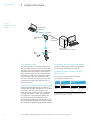
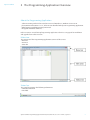
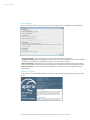
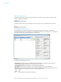
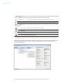
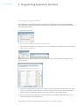
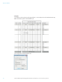
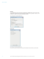
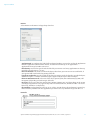
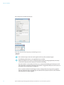
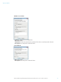
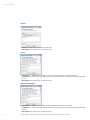
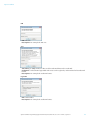
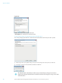
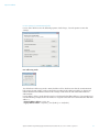
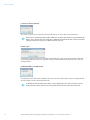
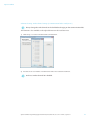
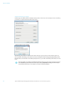
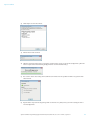
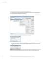
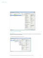
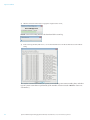
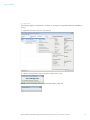
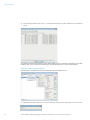
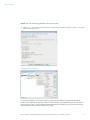
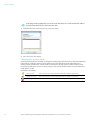
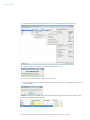
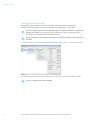
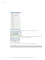
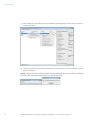
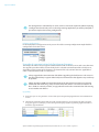
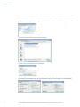
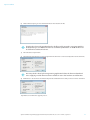
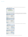
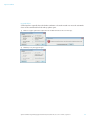
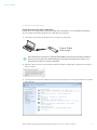
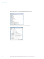
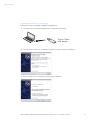
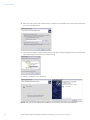
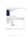
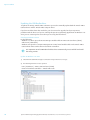
Aperio™ Online
Aperio
Online
Programming
Application
Manual
TM
Document No: ST-001321-A, Issue date: 8 July 2013
1
Aperio™ Online Quick Installation Guide, Document No: ST-001322-A, Date: 8 juli 2013
Aperio™ Online
Table of Contents
1Introduction.............................................................................................................................................. 3
Purpose..................................................................................................................................................................................3
Scope......................................................................................................................................................................................3
Applicable Products..........................................................................................................................................................3
Abbreviations and Definitions.......................................................................................................................................3
References............................................................................................................................................................................3
2 System Overview .................................................................................................................................... 4
The Aperio system.............................................................................................................................................................4
The Aperio programming application.......................................................................................................................4
Regulatory and security information..........................................................................................................................4
Communication hub versions and EAC interface...................................................................................................4
3 The Programming Application Overview....................................................................................... 5
About the Programming Application.........................................................................................................................5
Main view..............................................................................................................................................................................5
Status bar .............................................................................................................................................................................5
User settings........................................................................................................................................................................6
Software version ...............................................................................................................................................................6
USB radio indication.........................................................................................................................................................7
Installation View overview.............................................................................................................................................7
4 Programming Application Functions............................................................................................... 9
Opening/creating installations.....................................................................................................................................9
Scanning and adding communication hubs............................................................................................................9
Pairing locks/sensors with communication hub.................................................................................................. 10
Configure function - Wizard....................................................................................................................................... 12
Applying a stored configuration to a communication hub/lock/sensor..................................................... 38
Other lock/sensor functions........................................................................................................................................ 41
Retrieve system information...................................................................................................................................... 44
Change EAC address....................................................................................................................................................... 45
Changing the Security Mode...................................................................................................................................... 46
Changing the radio channels...................................................................................................................................... 48
Setting the time of a lock ............................................................................................................................................ 51
Importing and exporting configurations............................................................................................................... 53
Upgrade of communication hub/lock/sensor firmware................................................................................... 55
5 Installation of Programming Application and Drivers .............................................................60
Installation of the Programming Application and USB radio dongle........................................................... 60
Updating the USB Radio driver.................................................................................................................................. 70
6 Regulatory Information Regarding the Aperio USB Radio Dongle......................................76
Compliance....................................................................................................................................................................... 76
According to FCC15.247:............................................................................................................................................. 76
According to FCC15.105 (b) Information to the user....................................................................................... 76
Security Statement......................................................................................................................................................... 76
2
Aperio™ Online Programming Application Manual, Document No: ST-001322-A Date: 8 juli 2013
Aperio™ Online
1 Introduction
Purpose
The main purpose of this manual is to provide necessary information for a quick installation of
Aperio Online based products using the Aperio
Online Programming Application.
Applicable Products
This manual can be used for all versions of
communication hubs.
The manual is intended for installation
personnel, project managers and people with
similar responsibilities.
Scope
This manual includes a complete description
of all functionality and possible settings in the
Aperio Online Programming Application.
For quick installation instructions of a standard
Aperio online system including communication
hubs and locks/sensors. refer to ref [2], Aperio
Online Quick Installation Guide.
This manual is applicable to version 2.6.4 of the
Aperio Online Programming Application.
Abbreviations and Definitions
Abbreviation
EAC
DIP
RFID
Definition
Electronic Access Control. The system controlling access decisions.
Dual in-line Package. A manual electric switch used for settings on the
communcation hub.
Radio Frequency Identification. The credential technology used.
References
[1]
[2]
ST-001323-Aperio Online Mechanical Installation Manual
ST-001322-Aperio Online Quick Installation Guide
Aperio™ Online Programming Application Manual, Document No: ST-001321-A Date: 8 juli 2013
3
Aperio™ Online
2 System Overview
Figure 1.
Aperio technology
overview
Programming
application
IEEE802.15.4 (2.4GHz)
Communication
Hub
RS-485
or Wiegand
EAC system
(Electronic Access Control)
RFID
card
Lock
The Aperio system
The Aperio system is used in the following way:
The user holds an RFID card in front of the lock.
The lock sends card credentials wirelessly to the
communication hub and the communication
hub (wired through RS-485 or Wiegand) then
communicates with an EAC (Electronic Access
Control) system. The EAC system then makes
the access decision. The decision is sent via the
communication hub to the lock and access is
granted or denied.
The Aperio programming application
The Programming Application is used for the
configuration of a door installation. It is installed
on a laptop. The laptop has an Aperio USB
radio device connected to one of its USB ports.
The USB radio device enables the application
to connect via a communication hub to the
door lock. The lock communicates via the
communication hub either with the EAC or with
the Programming Application. Read more in the
Aperio Online Programming Application Manual.
4
Regulatory and security information
See section "6 Regulatory Information Regarding
the Aperio USB Radio Dongle" on page 76.
Communication hub versions and
EAC interface
There are four communication hub types
according to the table below:
Version
AH15
AH20
AH30
Maximum number of
locks/units
Wiegand/RS 485* 1
Wiegand
1
8
1
RS-485
(EAC address (EAC address
1-15)
15-63)
Interface
*) The firmware type loaded into the communication hub
controls what interface is enabled.
Aperio™ Online Programming Application Manual, Document No: ST-001322-A Date: 8 juli 2013
Aperio™ Online
3 The Programming Application Overview
About the Programming Application
∙∙ Software running under 32-bit or 64-bit versions of Windows 7, Windows 8 Vista or XP.
∙∙ Java Runtime Environment 1.7.13, 32-bit version bundled with Aperio Programming Application.
∙∙ Multi-language installation management tool.
∙∙ Encrypted installation database.
Refer to section "5 Installation of Programming Application and Drivers" on page 60 for installation
and upgrade from earlier versions.
Main view
The main view of the Programming Application consists of three areas:
∙∙ Menu bar
∙∙ View area
∙∙ Status bar
Status bar
The status bar contains the following information:
∙∙ USB Radio indication
∙∙ Date label
Aperio™ Online Programming Application Manual, Document No: ST-001321-A Date: 8 juli 2013
5
Aperio™ Online
User settings
The User Settings (on the Settings menu) contains settings that are applicable to all installations:
∙∙ Language settings: Select the language used by the Programming Application.
∙∙ Serial port settings: Automatically detects USB radio at start up: Uncheck this option to manually
specify the port used by the USB Radio Dongle, in case of hardware conflict.
∙∙ Advanced settings: Check this box if you need to perform advanced hub and lock configurations:
keypad configuration, advanced settings (changing the radio channel) and advanced lock settings.
∙∙ Log Level Settings: Used for trouble shooting purposes. Contact your Aperio supplier for more
information.
Software version
To check the version of installed software, select About Aperio Programming Application on the Help
menu:
6
Aperio™ Online Programming Application Manual, Document No: ST-001322-A Date: 8 juli 2013
Aperio™ Online
USB radio indication
USB Radio together with a green check mark indicates that the serial port used is ok and the radio
device is ready to transmit data.
USB Radio together with a red dot indicates that the serial port or the USB radio device is not ok.
Installation View overview
The installation view is the main window when working with door installations. This window is
automatically displayed after logging in to an installation and after the scanning process. To display it
manually, enter the Views menu and select Installation view.
The following information is shown:
∙∙ Lock/sensor: Indicates if there is a lock/sensor paired with the communication hub. If there is a
paired lock/sensor the MAC address of the lock/sensor is shown.
∙∙ Communication hub: The MAC address of the communication hub.
∙∙ EAC Address: Shows the EAC address for the lock paired with this communication hub.
∙∙ UHF Link: Indicates the strength of the UHF wireless link (through the USB Radio device) between
the communication hub and the Aperio Programming Application.
Green:Good
Yellow:OK
Red: Not OK (firmware upgrade not allowed)
Aperio™ Online Programming Application Manual, Document No: ST-001321-A Date: 8 juli 2013
7
Aperio™ Online
∙∙ Security Mode: Indicates the security mode of the communication hub. During final installation all
locks and hubs must be changed from Manufacturer mode to Customer mode.
Customer mode
Door is using secure radio communication with the customer encryption key.
Manufacturer mode
Door is using insecure radio communication with the default encryption key.
∙∙ Warning indications: The following warning levels are given. Hoover with the mouse to see more
information.
For example: Security mode for communication hub is undefined.
For example: The communication hub firmware (rfif) version is older than Aperio Programming
Application.
For example: The communication hub is not paired with any lock.
For example: The security modes in communication hub and lock are not equal and should be changed,
see section "Change EAC address" on page 45.
∙∙ Detailed information of selected hub and lock/sensor is shown on the right side of the window.
Right clicking a communication hub or lock/sensor will give access to the functions available in the
Programming Application. See chapter "4 Programming Application Functions" on page 9 for an
overview of all functions.
8
Aperio™ Online Programming Application Manual, Document No: ST-001322-A Date: 8 juli 2013
Aperio™ Online
4 Programming Application Functions
Opening/creating installations
An installation is a password protected set of settings you need when you want to communicate
with a hub and/or a lock. An installation is linked to an encryption file that is needed in order for the
communication to work.
1) Select File - New or Open.
Scanning and adding communication hubs
1) After opening an installation the scanning process starts automatically. To manually scan for communication
hubs, select Scan - Quick Scan.
Result: All communication hubs within reach of the USB Radio device of your computer are displayed in the
scan result table.
2) Locate a communication hub by the last four characters of the communication hub MAC address (ex. 01CF)
in the scan result table. The same characters should be on a label on the cover of the communication hub.
Click Rescan if the communication hubs that you want to configure are not shown in the list.
3) Select the communication hub(s) that you want to include in your installation. Click Show details to view
detailed information in the installation view.
Aperio™ Online Programming Application Manual, Document No: ST-001321-A Date: 8 juli 2013
9
Aperio™ Online
Pairing locks/sensors with communication hub
AH30 version of the communication hub can be paired with a combination of up to 8 locks/sensors.
AH15/AH20 can manage one lock/sensor.
1) Right click and select Communication hub - Pair with lock or sensor.
2) The pairing process starts. Hold the credential at the lock, or engage the magnet for the sensor to pair the
hardware with the communication hub.
10
Aperio™ Online Programming Application Manual, Document No: ST-001322-A Date: 8 juli 2013
Aperio™ Online
3) When the lock has stopped blinking you can click Done to see the pairing result.
Result: The result is displayed.
Aperio™ Online Programming Application Manual, Document No: ST-001321-A Date: 8 juli 2013
11
Aperio™ Online
Configure function - Wizard
Open the configure function by right clicking a communication hub or lock/sensor and selecting
Configure.
Depending on the hardware, different windows will appear in the wizard.
Security mode, radio channels and status message interval will be applied only to the lock/
sensor or the communication hub, depending on which hardware menu that was selected
on the right click menu.
The following sections describe each window in the wizard.
RFID configuration (Lock/sensor)
A corresponding firmware for the given RFID type must be installed on the locks/sensors.
Click Add/Change to enter the settings for each credential type.
12
Aperio™ Online Programming Application Manual, Document No: ST-001322-A Date: 8 juli 2013
Aperio™ Online
MIFARE Classic UID (Default)
No settings are made to MIFARE Classic UID.
If you want to prevent MIFARE Classic from being read at all by the lock, uncheck Use MIFARE Classic
RFID.
MIFARE Classic Sector
Select MIFARE Classic Sector in the RFID Card Type drop down list.
∙∙ Start Address in Sector: Parts of blocks within a sector can be used for credential data: 0 to 47 for
1K MIFARE Classic credentials. For 4K MIFARE Classic credential 0-47 (Start sector 0 to 31) and 0 –
239 (Start sector above 31)
∙∙ Length to read in Sector: Length of the credential data: 1 - 48 (Start sector above 31 we cannot use
a credential larger than 48 bytes even though we have more blocks available in these sectors.
∙∙ MIFARE Authentication Key: A 16 bytes long hexadecimal key is required to read the credential
data: For example: 00112233445566778899AABBCCDDEEFF
∙∙ Read Key: Select the read key that the credential is configured to use for sector reading. The lock/
sensor will give access only for this key.
If key B is selected as sector data read key, make sure that the access bits on the credential
prevent reading of key B. If key B is readable on the credential, key B cannot be used to read
the credential data.
Aperio™ Online Programming Application Manual, Document No: ST-001321-A Date: 8 juli 2013
13
Aperio™ Online
Example:
To read the user data shown in the figure below, 17 10 19 80, and use the Authentication Key
001122334455 together with MIFARE Key A.
The configuration should look like this:
14
Aperio™ Online Programming Application Manual, Document No: ST-001322-A Date: 8 juli 2013
Aperio™ Online
MIFARE Plus UID
No settings are made to MIFARE Classic UID.
If you want to prevent MIFARE Plus UID from being read at all by the lock, uncheck Use MIFARE Plus
RFID.
MIFARE Plus Sector
Select MIFARE Plus Sector in the RFID Card Type drop down list.
∙∙ Start Address in Sector: Parts of blocks within a sector can be used for credential data: 0 to 47 for
1K MIFARE Classic credentials. For 4K MIFARE Classic credentials 0-47 (Start sector 0 to 31) and 0 –
239 (Start sector above 31)
∙∙ Length to read in Sector: Length of the credential data: 1 - 48 (Start sector above 31 we cannot use
a credential larger than 48 bytes even though we have more blocks available in these sectors.
∙∙ MIFARE Authentication Key: A 16 bytes long hexadecimal key is required to read the credential
data: For example: 00112233445566778899AABBCCDDEEFF
∙∙ Read Key: Select the read key that the credential is configured to use for sector reading. The lock
will give access only for this key.
If key B is selected as sector data read key, make sure that the access bits on the credential
prevent reading of key B. If key B is readable on the credential, key B cannot be used to read
the credential data.
Aperio™ Online Programming Application Manual, Document No: ST-001321-A Date: 8 juli 2013
15
Aperio™ Online
Example:
Since MIFARE Plus has the same memory organization as MIFARE Classic, we can use the same
configuration. We will also use Key A but here the length of this key should be 16 bytes, in this
particular case: 00112233445566778899AABBCCDDEEFF.
The configuration should look like this:
DESFire UID
No settings are made to DESFire UID.
If you want to prevent DESFire from being read at all by the lock, uncheck Use DESFire RFID.
16
Aperio™ Online Programming Application Manual, Document No: ST-001322-A Date: 8 juli 2013
Aperio™ Online
DESFire
Select DESFire in the RFID Card Type drop down list.
∙∙ Application Id: To configure the lock for file credential reading, you need to set first the Application
Id of the application which contains the file. A credential can have up to 32 applications.
Application Ids range from 0 to 16777215.
∙∙ File Identity: You need to type the File Id of the file you want to read. Every application can have up
to 28 files. File Ids range is 1 to 255.
∙∙ File Start Position: You need to indicate the byte index where you want to start to read the file. If
you type 0 it will start from the beginning of the file.
∙∙ Length to read in File: Type the length of the data you want to read. The length is specified in bytes.
Minimum length is 1 and the maximum length supported by the Aperio lock is 48 bytes.
∙∙ File Data Protection Level: Select one of the three options (Plain, Data Authenticity by MAC, Full
Encryption) depending on the data type of the file.
∙∙ Key Type: Select one of the four options (DES, 2K3DES, 3K3DES, AES-128) depending on the crypto
used by your application’s key. Type the key value in hexadecimal. DES, 2K3DES and AES-128 are 16
bytes keys, 3K3DES is a 24 bytes key.
∙∙ Key Number: Each application can store up to 14 keys. Key 0 is always the application’s master key.
Enter which key number from the application you want to use. Key numbers range from 0 to 13.
Example:
Aperio™ Online Programming Application Manual, Document No: ST-001321-A Date: 8 juli 2013
17
Aperio™ Online
The configuration should look like this:
Low frequency
In the list, select the low frequency credential type to use:
∙∙ HID Prox
∙∙ EM Prox
This credential type cannot be used together with any other credential types.
The following information is not applicable for US market:
Before the lock/sensor has been configured with the Programming Application, the lock/
sensor will accept any Low Frequency credential technology.
Once the lock has successfully read 3 times any credential technology the lock/sensor will
only accept this credential technology. If the power is toggled the lock/sensor will return to
the initial state of accepting any credential.
Once a specific credential technology has been configured via the Programming Application, this will be the only accepted type of credential. The lock will remain in this condition
after the power has been toggled.
18
Aperio™ Online Programming Application Manual, Document No: ST-001322-A Date: 8 juli 2013
Aperio™ Online
Legic UID
In the list, select the card type to use:
∙∙ Prime
∙∙ ISO 15693 (Advant)
∙∙ ISO 1443 A (Advant)
No other settings are made to Legic UID.
Aperio™ Online Programming Application Manual, Document No: ST-001321-A Date: 8 juli 2013
19
Aperio™ Online
Legic UID with data
In the list, select the card type to use:
∙∙ Prime
∙∙ ISO 15693 (Advant)
∙∙ ISO 1443 A (Advant)
Select UID with data in the drop down list.
Segment search:
∙∙ Search string (hex): Max 24 characters hexadecimal, even number. For example: 30030009.
∙∙ Segment type filter: The type of segment, None, Access or Data.
∙∙ Start segment: Specifies the segment from which to start the search. It is useful in cases where more
than one similar search string exists. Integer in the range of 0-255.
Data:
∙∙ Use the first byte of the search string as address 0 for Advant: Only for Advant card types, in order to
change the data addressing of Advant. The first data byte will be the first search string/stamp byte.
∙∙ Start address: Specifies the start address of the data. Integer in the range of 0-255.
∙∙ Number of bytes: Specifies the number of bytes of data to be read. Integer in the range of 1-45.
Checksum:
∙∙ Type: "None" does not require any of the checksum related fields to be specified, but CRC 8-bit and
16-bit does.
∙∙ Data start address: Specifies the address where the data which checksum is to be calculated starts.
Integer in the range of 0-255.
20
Aperio™ Online Programming Application Manual, Document No: ST-001322-A Date: 8 juli 2013
Aperio™ Online
∙∙ Data length: Specifies the length of the data in number of bytes to be read. Integer in the range of
0-255.
∙∙ Checksum address: Specifies the address where the checksum is located. Integer in the range of
0-255.
The credential data start address differs between Legic Prime and Legic Advant:
∙∙ For Legic Prime cards the first data byte starts with the first search string/stamp byte.
∙∙ For Legic Advant cards the first data byte starts with the first byte in the data area.
Example: Legic Advant Card
Segment 0:
Search String: 30 03 00 08
Segment type: Data
Data length: 8 bytes
Checksum: CRC 16 byte 0-5
Checksum address: 6
Aperio™ Online Programming Application Manual, Document No: ST-001321-A Date: 8 juli 2013
21
Aperio™ Online
Segment 1:
Search String: 30 03 00 09
Segment type: Access
Data length: 24 bytes
Checksum 1: CRC 16 byte 0-10
Checksum 1 address: 11
Checksum 2: CRC 16 byte 13-21
Checksum 2 address: 22
or
Only one checksum can be selected.
To include the search string in the first data byte, check the Use the first byte of the search string as
address 0 for Advant.
22
Aperio™ Online Programming Application Manual, Document No: ST-001322-A Date: 8 juli 2013
Aperio™ Online
Example: Legic Prime Card
Segment 0: (only segment)
Search String: 30 03 00 08
Segment type: Data
Data length: 8 bytes
Checksum: CRC 8 byte 0-6
Checksum address: 7
Aperio™ Online Programming Application Manual, Document No: ST-001321-A Date: 8 juli 2013
23
Aperio™ Online
Advanced settings - Keypad configuration (Lock)
This window is only visible if Show advanced settings is activated in User Settings window, see
section "User settings" on page 6.
1) Click Change to enter specific Keypad configuration.
2) Choose between two reading modes:
∙∙ Fixed length: PIN is set to use a fixed length.
∙∙ Enter PIN length: A value between 1 and 16, as specified by the EAC.
∙∙ End character: PIN is sent to the EAC after an end character is pressed.
∙∙ Select Character: One of the non-numeric characters on the keypad can be used to submit the pin.
For example: The user enters the PIN followed by a # on the keypad.
24
Aperio™ Online Programming Application Manual, Document No: ST-001322-A Date: 8 juli 2013
Aperio™ Online
Override credential (Lock)
The override credentials are used to gain access to an area when the EAC is offline or when the lock
has lost connection with the communication hub. Only the credentials from the override list will be
granted access when the system is offline. You may add 10 override credentials to a door.
Use of override credentials when using a Wiegand hub requires that DIP switch 1 is set to
position ON.
Tip: You do not have to enter the override credential data manually for every door to be configured.
This can be saved using the Save configuration function as the last step of the configuration wizard.
1) To add an override credential, select the desired card type in the drop down list and click Add.
See the list below for a description of each credential.
If you check Remove all credentials in the lock, all existing override credentials in the lock
will be deleted during the configuration process.
Aperio™ Online Programming Application Manual, Document No: ST-001321-A Date: 8 juli 2013
25
Aperio™ Online
MIFARE UID
∙∙ Card Type: MIFARE Classic or MIFARE Plus
∙∙ UID: Card number
∙∙ Description: For example the credential owner.
MIFARE Sector
∙∙ Card Type: MIFARE Classic or MIFARE Plus
∙∙ Sector data: Sector data stored on the credential. This value is normally stored in the EAC.
∙∙ Description: For example the credential owner.
26
Aperio™ Online Programming Application Manual, Document No: ST-001322-A Date: 8 juli 2013
Aperio™ Online
MIFARE Sector and UID
∙∙ Card Type: MIFARE Classic or MIFARE Plus
∙∙ UID: Card number
∙∙ Sector data: Sector data stored on the credential. This value is normally stored in the EAC.
∙∙ Description: For example the credential owner.
ISO 14443B UID
∙∙ UID: Card number.
∙∙ Description: For example the credential owner.
Aperio™ Online Programming Application Manual, Document No: ST-001321-A Date: 8 juli 2013
27
Aperio™ Online
DESFire
∙∙ File data: The file data stored on the credential.
∙∙ Description: For example the credential owner.
iCLASS
∙∙ Size in bits [1…144]: Number of bits used for credential data on the iCLASS credential.
∙∙ Credential: Card credential appended with zeroes on the right side, and translated to hexadecimal
format.
∙∙ Description: For example the credential owner.
HID prox and EM prox
∙∙ Size in bits [1…144]: Number of bits used for credential data on the credential.
∙∙ Credential: Card credential appended with zeroes on the right side, and translated to hexadecimal
format.
∙∙ Description: For example the credential owner.
28
Aperio™ Online Programming Application Manual, Document No: ST-001322-A Date: 8 juli 2013
Aperio™ Online
PIN
∙∙ PIN: PIN code
∙∙ Description: For example the PIN user.
Seos
∙∙ Size in bits [1…384]: Number of bits used for credential data on the credential.
∙∙ Credential: Card credential appended with zeroes on the right side, and translated to hexadecimal
format.
∙∙ Description: For example the credential owner.
Legic UID
∙∙ UID: Card number.
∙∙ Description: For example the credential owner.
Aperio™ Online Programming Application Manual, Document No: ST-001321-A Date: 8 juli 2013
29
Aperio™ Online
Legic Data
∙∙ Data: Sector data stored on the credential.
∙∙ Description: For example the credential owner.
Security Mode Settings (Communication hub and Lock/sensor)
This setting will apply for both the communication hub and the lock if only one lock is paired.
1) Click Change in the Security Mode Setting area if you want to change the security mode, or click Next.
2) To change to customer mode, check the checkbox and click OK.
The default mode is Manufacturer mode, but you should always change it to Customer
mode. If you change to Manufacturer mode key the lock will no longer be using secure radio
communication.
30
Aperio™ Online Programming Application Manual, Document No: ST-001322-A Date: 8 juli 2013
Aperio™ Online
RS-485 settings (Communication hub)
For use of RS-485 there are the following options. Click Change... for each option to enter the
settings.
EAC addressing mode
The default EAC addressing mode is Normal address offset, which means that the communication
hub assigns the EAC address to the paired locks according to the addressing table, see the Aperio
Online Mechanical Installation manual. This setting is used when the EAC can handle addresses
without limit.
Legacy address offset is used when the EAC has a low limit for handling addresses, for example 32 or
64. The following example shows the addresses assigned to the locks on a communication hub with
address 1:
∙∙ Normal address offset: 1,17,33, 49,
∙∙ Legacy address offset: 1-8 (hub 1), 9-16 (hub 2), 17-24 (hub 3).
Aperio™ Online Programming Application Manual, Document No: ST-001321-A Date: 8 juli 2013
31
Aperio™ Online
Lock access decision timeout
This value sets the time (in seconds) the lock will wait for an access decision from the EAC.
If this time is extended and the HUB is offline the response time when using the PAP will be
longer. This is due to that each swipe of a credential will wait for the EAC response and with
a longer timeout, the response in offline will also increase.
Remote open
Checking the Enable remote open checkbox will enable the remote open functionality in the HUB.
As the wiegand interface does not support setting an unlock duration from the EAC, this must be
configured here.
Enable EAC Address via DIP Switch
Checking the Enable DIP Switch checkbox will restore the EAC addressing to what is configured with
the DIP switches on the communication hub.
To disable the DIP switch the EAC address must digitally be set as well. To do this use the
Change the EAC address function on the right click menu for the communication hub.
32
Aperio™ Online Programming Application Manual, Document No: ST-001322-A Date: 8 juli 2013
Aperio™ Online
Advanced setting - Radio channel settings (Communication hub or Lock/sensor)
Always change the radio channel on the lock before changing on the communication hub.
This function is also available on the right click menu in the installation view.
1) Click Change... to set the radio channel the communication.
2) Deselect one or several of the used channels to make a new selection of channels.
For the US market channel 26 is disabled.
Aperio™ Online Programming Application Manual, Document No: ST-001321-A Date: 8 juli 2013
33
Aperio™ Online
Advanced Lock/sensor Settings
On this page you will be able to configure Battery Power Alarm Interval, Status Report Interval, Locking
Parameters, Card Read Indication and Sensor Events.
Configure Battery Power Alarm
The battery power alarm is sent from the lock to the EAC system and is used to indicate when it is
time to replace the battery. It may be necessary to configure the alarm triggering depending on the
type of battery used and the surrounding temperature, e.g. in cold surroundings the battery runs out
faster.
This only applies to products with lithium batteries that are using energy counter. For products with battery measurement on the secure side (P100/I100 currently), the interval you
set translates into hours, i.e. 6 minutes = 6 hours on those products.
34
Aperio™ Online Programming Application Manual, Document No: ST-001322-A Date: 8 juli 2013
Aperio™ Online
Status Report Interval
The interval setting is normally set to 60 minutes. If Remote Open functionality is used, this parameter
should be set to a shorter interval such somewhere in between 5 and 15 minutes.
Lowering the status interval time for any reason will have an adverse effect on the battery
life of the product.
As the status message interval is used by the communication hub to detect if the lock has gone
offline, any changes to this interval must be done on both lock and communication hub where the
lock interval should be shorter than the interval in the communication hub. This is to ensure that no
intermittent offline situations occur.
When using an AH30 communication hub it is also important that all locks have the same status
interval as the communication hub will only have one ‘offline’ interval for all locks paired.
Locking Parameters
Here you configure timing for different operations in the lock:
∙∙ Try to unlock timeout (seconds): How long the lock tries to unlock before it returns a failure.
∙∙ Lock open time (seconds): How long the lock will be open in seconds (default = 5 s).
Aperio™ Online Programming Application Manual, Document No: ST-001321-A Date: 8 juli 2013
35
Aperio™ Online
∙∙ Lock jammed alarm timeout (seconds): How long time the system tries to lock the lock before it
sends an alarm to the EAC and goes back to idle state.
∙∙ Enable lock jammed retry: This enables a periodic retry to lock the lock according the settings
under “Lock jammed retry period (seconds).
∙∙ Lock jammed retry period (seconds): How long the lock will wait before it retries to lock the lock
in seconds (default = 2 s).
∙∙ Lock jammed indication mode: The way in which the lock indicates that it has been jammed. LED,
Buzzer and LED and buzzer are the different indication modes.
Configure Card Read Indication
Different locks can have a different mechanism for audio-visual indication of successful credential
reading. Here it is possible to disable credential read indication or to set it to LED. Some Aperio locks
have support for other mechanisms such as buzzers.
Sensor
This setting applies for locks with built in sensor. By activating this function, the lock sensor will stop
sending passage events to the EAC for unlock durations longer than you set here. This setting will
save battery life in high traffic doors.
Device update page – Saving Configuration
Here a summary of configurations that will be transferred to the unit. The Device Update dialog box
shows a summary of the configuration tasks that will be downloaded to communication hub/lock/
sensor. The configuration may be used later to configure other devices with the same information, by
clicking Save configuration:
36
Aperio™ Online Programming Application Manual, Document No: ST-001322-A Date: 8 juli 2013
Aperio™ Online
1) The Save Configuration dialog box shows a summary of the configuration tasks that have been collected
during the different steps in the Configuration Wizard. You can exclude some tasks by simply ticking the
check box.
2) Recommended tasks to save could be:
∙∙ RFID configuration
∙∙ Change security mode
∙∙ Override credential
∙∙ Device time update
∙∙ And optionally some advanced features like Battery Alarm, Status configuration and Locking parameters).
If you choose to save a configuration, keep in mind that some configuration settings should not
be saved. Only save settings that are general for all locks in your installation. Tip: Create a set of
configurations for the most common settings in your system.
3) Enter a unique and suitable name for this configuration in the Configuration name field. Choose this name
carefully, to make it clear what settings are changed in the lock/sensor or communication hub.. You could,
for instance, name it according to the different configuration tasks or, if applicable, use a name that reflects
the specific door type.
Aperio™ Online Programming Application Manual, Document No: ST-001321-A Date: 8 juli 2013
37
Aperio™ Online
4) Click OK.
Result: The configuration is saved in the local storage and the Save configuration window is closed.
Clicking Cancel on the Device Update page does not affect the locally stored configuration.
Applying a stored configuration to a communication hub/lock/sensor
If you saved a configuration in the configuration wizard, you can apply it to numerous locks/sensors.
This function is available on both the Lock/sensor menu and the communication hub menu and will
only download settings that apply for the hardware selected.
Follow these steps to download a saved configuration to a lock/sensor:
1) In the Installation view, right click the desired lock/sensor and select Apply configuration and an earlier stored
configuration.
38
Aperio™ Online Programming Application Manual, Document No: ST-001322-A Date: 8 juli 2013
Aperio™ Online
2) Click Confirm to start the transfer.
3) Wait for the transfer to finish.
4) Hold the credential at the lock, or engage the magnet for the sensor, to accept the configuration. (This will
not be required when downloading configuration to a communication hub.)
5) The result is shown. The settings that could not be transferred to the specific hardware are ignored. Click
Close to finish.
6) Repeat all the steps from the beginning of this section for every lock/sensor you want to configure with a
saved configuration.
Aperio™ Online Programming Application Manual, Document No: ST-001321-A Date: 8 juli 2013
39
Aperio™ Online
Change physical location name – communication hub/lock/sensor
This function applies to both communication hubs and locks/sensors. In the example below the
physical location name is changed for a lock/sensor.
1) Right click and select Lock/sensor – Change physical location name…
2) Enter a description that clearly identifies the lock position and click OK.
3) For a communication hub the information is updated immediately. If you change the physical location name
for a lock/sensor you will be prompted to hold the credential at the lock, or engage the magnet for the
sensor.
Result: After successful reading a progress bar shows the download. After update the new location
name can be found in the Lock/sensor section on the lower right side of the installation view.
40
Aperio™ Online Programming Application Manual, Document No: ST-001322-A Date: 8 juli 2013
Aperio™ Online
Other lock/sensor functions
Get Event Log
This function displays the event log for a particular lock (not available for sensor), where you can find
all system events performed on the lock.
1) Right click and select Lock/sensor – Get Event Log.
Aperio™ Online Programming Application Manual, Document No: ST-001321-A Date: 8 juli 2013
41
Aperio™ Online
2) Hold the credential at the lock, or engage the magnet for the sensor,.
Result: Successful reading initiates the download of the event log.
3) In the event log window, click Save As... to save the information to a txt file or click Close to exit without
saving.
The window contains information of system events including consecutive number, date, and what
type of system event that was performed. (If the number of events exceeds 200 older events are
overwritten.)
42
Aperio™ Online Programming Application Manual, Document No: ST-001322-A Date: 8 juli 2013
Aperio™ Online
Get Audit Trail
This function displays a complete list of all access attempts for a particular lock (not available for
sensor).
1) Right click and select Lock/sensor – Get Audit Trail.
2) Hold the credential at the lock, or engage the magnet for the sensor.
Result: Successful reading initiates the download of the audit trail.
Aperio™ Online Programming Application Manual, Document No: ST-001321-A Date: 8 juli 2013
43
Aperio™ Online
3) In the audit trail window, click Save As... to save the information to a txt file or click Close to exit without
saving.
The window contains information on the total number of access attempts including consecutive
number, date, access decision and what type of credential that was used at each attempt.
Retrieve system information
This function is available for both communication hub and lock/sensors.
1) Right click and select Lock/sensor or Communication Hub – Retrieve system information to access the unit.
44
Aperio™ Online Programming Application Manual, Document No: ST-001322-A Date: 8 juli 2013
Aperio™ Online
Result: The Programming Application connects to the unit.
2) Click Save as... to save the system information to a local storage, Click Reset diagnostic counters... to reset the
device or click Close to exit.
Change EAC address
It is recommended to use the DIP Switch for setting the EAC address of communication hubs.
However, if needed the Change EAC address function allows you to digitally assign an EAC address
in the range of 1-63 (1-15 for communication hubs with several locks/sensors paired and 1-63 for
communication hubs with one lock/sensor paired).
Aperio™ Online Programming Application Manual, Document No: ST-001321-A Date: 8 juli 2013
45
Aperio™ Online
If the Programming Application is used to set RS 485 addresses, it will override the address
set by the DIP switch on the communication hub.
1) Right click and select Communication hub– Change EAC Address.
2) Select the address and click OK.
Changing the Security Mode
Secure communication is normally set during first configuration of locks/sensors and communication
hubs with the configure wizard. Security mode is also accessible through the right click menu.
During normal operation the security mode should not be altered. However, if the hardware must
be sent to the factory for service or repair purposes, the security mode must be set to manufacturer
mode before service.
Explanation of symbols:
46
Customer mode
Door is using secure radio communication with the customer encryption key.
Manufacturer mode
Door is using insecure radio communication with the default encryption key.
Conflicting mode
The modes in the lock/sensor and the communication hub are not the same.
Aperio™ Online Programming Application Manual, Document No: ST-001322-A Date: 8 juli 2013
Aperio™ Online
1) Right click the lock/sensor and select Switch to Customer Mode/Switch to Manufacturer mode.
2) Hold the credential at the lock, or engage the magnet for the sensor.
3) A progress bar shows that the transfer is being performed.
4) If the encryption key is successfully loaded you get a message that states “Successfully updated security
mode”. Click OK.
Result: Check the lock symbol at the right side of the door to see that the door has been set to
Customer mode/Manufacturer mode.
Aperio™ Online Programming Application Manual, Document No: ST-001321-A Date: 8 juli 2013
47
Aperio™ Online
Changing the radio channels
Changing the radio channels can be necessary if you experience interference between
communication hubs, which can occur if many hubs are installed close to each other..
To use this function, you must have the Show advanced settings checkbox checked in User
Settings, see section "User settings" on page 6. Follow these steps to change the radio
channel for the communication hub and lock/sensor:
Always change the radio channel in the locks/sensors before changing in the communication hub!
1) Select the lock/sensor in the scan result table. Right click and select Lock/sensor – Change radio channels.
2) Uncheck any of the three currently used channels to be able to select other radio channels. Click OK.
For the US market channel 26 is disabled.
48
Aperio™ Online Programming Application Manual, Document No: ST-001322-A Date: 8 juli 2013
Aperio™ Online
3) Hold the credential at the lock, or engage the magnet for the sensor to perform the update.
Result: A progress bar shows that the update is being performed. The Device update result dialog
box shows the result of the update when it has been performed.
4) Repeat this procedure for all locks/sensors connected to the current communication hub.
Recommendation: Although it is possible to set different channels to locks/sensors paired with
one hub, it is preferable to use the same three channels for all locks/sensors on that communication
hub in order to create a more stable radio connection. Communication problems occur more likely
between closely installed hubs than between closely installed locks/sensors paired with one hub.
Aperio™ Online Programming Application Manual, Document No: ST-001321-A Date: 8 juli 2013
49
Aperio™ Online
5) Finally, change the radio channel for the communication hub: Right click and select Communication Hub –
Change radio channels.
6) Uncheck any of the three currently used channels to be able to select the same radio channels as for the
lock/sensor. Click OK.
Result: A progress bar shows that the update is being performed. The Device update result dialog
box shows the result of the update when it has been performed.
50
Aperio™ Online Programming Application Manual, Document No: ST-001322-A Date: 8 juli 2013
Aperio™ Online
Setting the time of a lock
Follow these steps to set the time of a lock:
1) Select a lock in the installation view.
2) On the menu bar select Views–Installation Configuration and check that the Update device time during door
configuration checkbox is checked.
3) Close the Installation Configuration view. Right click and select Lock/sensor-Configure. Click Next repeatedly
until you reach the Device Update window.
Aperio™ Online Programming Application Manual, Document No: ST-001321-A Date: 8 juli 2013
51
Aperio™ Online
4) Click Next.
5) Hold the credential at the lock, to update the time.
The time of the lock will now be automatically set each time you configure and update the
device.
6) Click Close to exit the device update configuration.
52
Aperio™ Online Programming Application Manual, Document No: ST-001322-A Date: 8 juli 2013
Aperio™ Online
Importing and exporting configurations
General
The stored configurations made in the configuration wizard, can be exported to a file so that more
than one Aperio Programming Application can share the same configuration information. When
you import an exported configuration you add it to the local configuration storage and then you can
apply that configuration to a lock/sensor or communication hub.
When you export a configuration, you cannot change the name of the configuration, only
the file name holding the configuration information. Since configurations can be shared
between different Aperio Programming Applications, it is preferable that a shared configuration (identified by its unique name) also has the same meaning on all Aperio Programming
Applications. It is therefore advisable that you choose the name of the configuration wisely
when you store the configuration.
Exporting Configuration
1) On the File menu, select Export/Import Configurations.
2) Select the configuration that should be exported to file and click Export.
3) Select the folder where you want to store the configuration, select a filename and click Save.
Aperio™ Online Programming Application Manual, Document No: ST-001321-A Date: 8 juli 2013
53
Aperio™ Online
4) Choose a password that will be used when importing the particular configuration, confirm it and click OK.
Note that the password must contain at least 8 characters.
Importing Configuration
Importing a configuration takes a previously exported configuration and adds it to the local
configuration storage.
1) On the Views menu, select Export/Import Configurations View and click Import.
2) Select a valid configuration XML-file and click Open.
3) Enter the password and click OK.
54
Aperio™ Online Programming Application Manual, Document No: ST-001322-A Date: 8 juli 2013
Aperio™ Online
The configuration is identified by its name, not the name of the export file. When importing
a configuration that already exists in the Programming Application you will be prompted if
you want to replace the existing configuration.
Deleting configuration
In the Export/Import Configurations view you can also delete existing configurations: Right click the
configuration and select Delete.
Upgrade of communication hub/lock/sensor firmware
This chapter describes how to upgrade communication hubs and locks/sensors with a new firmware.
The upgrade procedure will be executed only for the selected communication hub or lock/sensor,
depending on the content of the firmware. The firmware file only contains firmware applicable to
either a communication hub or a lock/sensor.
Always upgrade the communication hub before upgrading the locks/sensors. The reason is
that hub should always support older lock/sensor firmware but the opposite may not always
be possible.
When upgrading AH30 communication hubs to the latest firmware, when using the DIP
switches for EAC addressing, always check that the DIP switch is set to the correct EAC address. If DIP 5 is active by mistake, an upgrade will result in the communication hub starting
to use another EAC address.
Upgrading
1) Ensure that you are using the latest version of the Aperio Programming Application. If not install the latest
version.
2) Check on the UHF Link indicator that the signal strength indicator is good enough to be able to perform
an upgrade (green or yellow). If you have bad signal strength (red) the Programming Application will not
enable the upgrade function.
Aperio™ Online Programming Application Manual, Document No: ST-001321-A Date: 8 juli 2013
55
Aperio™ Online
3) Right click on the communication hub/lock/sensor in the Installation view and select Upgrade Firmware.
4) Select the firmware file (.afw/.fw file) and click Open.
5) Enter the password supplied with the firmware.
Result: The firmware upgrade window is shown, with a list of the units that may be upgraded.
Depending on the firmware file, the list of firmware may vary. Two examples are shown below.
56
Aperio™ Online Programming Application Manual, Document No: ST-001322-A Date: 8 juli 2013
Aperio™ Online
6) Click on Release Info to get more information about the selected .afw file.
Check in the release info window that the .afw file used for upgrade is consistent with the
lock/cylinder type. A C100 afw file must be used with cylinder locks. An E100 afw file must
be used with escutcheon locks etc.
7) Close the Release Info window.
8) Check that the new firmware version is higher than the firmware version currently loaded on the hardware.
No sanity check is done by the Programming Application before the firmware download
starts. Applying an older firmware than installed can cause the hardware to malfunction.
9) All firmware is selected to be downloaded by default. Uncheck firmware that you do not wish to download.
10)Click Start to initiate the upgrade process.
Aperio™ Online Programming Application Manual, Document No: ST-001321-A Date: 8 juli 2013
57
Aperio™ Online
11)If you are upgrading a lock/sensor you will be prompted to hold a credential at the lock/engage sensor
before the download starts.
Result: The upgrade will start with the first selected firmware in the list. A green arrow to the left of
the selected firmware will indicate the firmware is being upgraded and the firmware is downloaded.
After finished download, the device resets.
12)Click Next to continue with the next firmware in the list. Or click Close to cancel the rest of the firmware
upgrade process.
13)After all firmware is downloaded, click Done.
58
Aperio™ Online Programming Application Manual, Document No: ST-001322-A Date: 8 juli 2013
Aperio™ Online
Upgrade failure
A failed update is typically due to bad radio conditions. The work around is to move the USB Radio
closer to the communication hub and try update again.
1) Click Save support information to file if desired and click OK to close the error message.
2) Click Retry to try the upgrade again.
Aperio™ Online Programming Application Manual, Document No: ST-001321-A Date: 8 juli 2013
59
Aperio™ Online
5 Installation of Programming Application and Drivers
Installation of the Programming Application and USB radio dongle
Computer specifications
The Aperio Online Programming Application should be installed on a computer with the following
specifications:
∙∙ Laptop
∙∙ 32/64-bit version of Windows 7, Windows 8, Vista or XP
∙∙ USB 2.0
Files needed for the installation
∙∙ Aperio Programming Application software version 2.6.4.X
∙∙ Encryption key file.
These files should be delivered from your lock distributor.
Installing the Programming Application
Follow these steps to install the Programming Application and the drivers necessary for installation
of the Radio dongle:
1) Unpack the Aperio distribution file (i.e. progapp-x.y.z.zip/progapp_US-x.y.z.zip), including the setup.exe file,
in a temporary folder.
2) Run the setup.exe file.
Result: The Aperio Programming Application is installed and necessary drivers for the Radio dongle
are copied to the computer.
The Aperio Programming Application is bundled with Java, so no separate Java installation is
required.
60
Aperio™ Online Programming Application Manual, Document No: ST-001322-A Date: 8 juli 2013
Aperio™ Online
Installing the USB Radio Dongle
Install USB radio dongle drivers in Windows 7
Follow these steps to install the USB radio dongle driver in Windows 7. For installation in Windows
XP see section "Install Radio dongle drivers in Windows XP" on page 67:
1) Connect the Aperio USB radio dongle device to a USB port on your laptop.
Tritech TriBee
USB dongle
Other USB devices containing a radio (like WLAN/WiFi) connected to the laptop should be
placed as far away from the USB Radio dongle as possible. If the radio link is weak, use an
USB extension cable or an external USB HUB.
2) Window 7 will not be able to automatically install the USB Radio and will display a notification according to
below, or similar.
3) You must perform a manual installation in the Device manager: Open the Control panel in Windows and click
Device Manager.
Aperio™ Online Programming Application Manual, Document No: ST-001321-A Date: 8 juli 2013
61
Aperio™ Online
4) Navigate to Other devices – TriBee USB and right click and select Properties.
5) In the Properties dialog, click the Driver tab and click Update Driver…
62
Aperio™ Online Programming Application Manual, Document No: ST-001322-A Date: 8 juli 2013
Aperio™ Online
6) In the Update Driver Software dialog click on Browse my computer for driver software.
7) If the Aperio Programming Application has been installed a typical path to the driver folder is C:\Program
Files\Assa Abloy\Aperio Programming Application\Tritech TriBee USB Driver.
Click Browse… to locate the driver folder. Then click Next.
8) Depending on the windows system history regarding driver installations you may have to confirm driver
installation. If so, select Install this driver software anyway.
Aperio™ Online Programming Application Manual, Document No: ST-001321-A Date: 8 juli 2013
63
Aperio™ Online
9) The first part of the installation is now done.
10)After the first part of the installation one or several notifications may be displayed and indicate that the unit
has not been correctly installed. This is normal and no corrections are necessary.
11)Click Close in the dialog boxes to return to the Device Manager. Navigate to Other Devices – USB Serial Port,
right click and select Properties.
64
Aperio™ Online Programming Application Manual, Document No: ST-001322-A Date: 8 juli 2013
Aperio™ Online
12)Repeat from step 5 until the second part of the driver is installed.
13)Reboot the computer.
14)The installation is now complete. If needed, enter the Device Manager to verify that the correct driver
version is installed for both the TriBee USB Serial Port (COMx) and the Tritech TriBee USB.
A check mark will appear in the left bottom corner after startup of the Programming Application,
showing the connection status with the USB Radio dongle.
Aperio™ Online Programming Application Manual, Document No: ST-001321-A Date: 8 juli 2013
65
Aperio™ Online
Install USB radio dongle drivers in Windows Vista
Follow these steps to install the USB radio dongle driver in Windows Vista:
1) Connect the Aperio USB Radio Dongle device to a USB port on your laptop.
Tritech TriBee
USB dongle
2) Click Cancel in the Found new Hardware dialog.
3) Perform a manual installation similar to the Windows 7 installation procedure in section "Install USB radio
dongle drivers in Windows 7" on page 61.
66
Aperio™ Online Programming Application Manual, Document No: ST-001322-A Date: 8 juli 2013
Aperio™ Online
Install Radio dongle drivers in Windows XP
Follow these steps to install the USB Radio Dongle driver:
1) Connect the Aperio USB Radio Dongle device to a USB port on your laptop.
Tritech TriBee
USB dongle
2) Select No, not this time (do not use Windows Update to search for software) and click Next.
3) Select Install from a list or specific location (Advanced) and click Next.
Aperio™ Online Programming Application Manual, Document No: ST-001321-A Date: 8 juli 2013
67
Aperio™ Online
4) Select Search for the best driver in these locations. Unselect Search removable media, select Include this location
in the search and click Browse.
5) Select the Tritech TriBee USB Driver folder located in the Aperio Programming Application main folder. Click
OK and then Next (in the Found New Hardware Wizard).
6) After the installation is done, click Finish.
Result: The system now displays the installation procedure for the TriBee USB Serial Port.
68
Aperio™ Online Programming Application Manual, Document No: ST-001322-A Date: 8 juli 2013
Aperio™ Online
7) Repeat steps 2–6 of this procedure for the serial port driver. When done, click Finish.
Result: Windows has installed the drivers and the hardware is ready to use. Windows shows a pop-up
message indicating if the driver installation was successful.
8) If needed, you can verify that the drivers for the TriTech TriBee USB (USB Controller) and the TriBee USB
Serial Port (Ports (COM & LPT)) are working by opening the Computer Management Control Panel:
Aperio™ Online Programming Application Manual, Document No: ST-001321-A Date: 8 juli 2013
69
Aperio™ Online
Updating the USB Radio driver
To update an existing Tritech TriBee USB Driver you need to manually update both the TriTech TriBee
USB bus driver and the Tritech TriBee USB port driver.
If you have an older driver that works fine, you do not need to upgrade, but if you experience
problems with the driver or if you are running the Aperio Programming Application on Windows 7 or
Vista, you are encouraged to ensure that you are using the latest driver.
Check current driver version
Do the following:
∙∙ Windows 7 or Vista: Open the Device Manager. Double-click on TriBee USB Serial Port (COMx)
under Ports (COM & LPT).
∙∙ Windows XP: Open the Computer Management Control Panel. Double-click on the Tritech TriBee
USB Serial Bus driver under Universal Serial Bus controllers.
It is important not to let Windows find the driver automatically, since it will fail and install
the wrong version.
Update in Windows 7 or Vista
1) Check that the USB Radio Dongle is connected and open the Device manager.
2) The following hardware is to be updated:
∙∙ Ports (COM & LPT) – TriBee USB Serial Port (COMx)
∙∙ Universal Serial Bus controllers – Tritech TriBee USB
70
Aperio™ Online Programming Application Manual, Document No: ST-001322-A Date: 8 juli 2013
Aperio™ Online
3) Double-click the TriBee USB Serial Port (COMx) driver under Ports (COM & LPT). Enter the Driver tab click
Update driver.
4) In the Update Driver Software dialog, click Browse my computer for driver software and click Next.
Aperio™ Online Programming Application Manual, Document No: ST-001321-A Date: 8 juli 2013
71
Aperio™ Online
5) Browse for the new driver and click Next.
6) Depending on the windows system history regarding driver installations you may have to confirm driver
installation. If so, select Install this driver software anyway.
72
Aperio™ Online Programming Application Manual, Document No: ST-001322-A Date: 8 juli 2013
Aperio™ Online
7) The first driver is now installed.
8) Click Close and go back to the Device Manager. Now double-click the Tritech TriBee USB driver under
Universal Bus controllers.
9) Install the second driver by repeating from step 3. When done the same message as above (Windows has
now updated driver software) is displayed.
10)Reboot Windows and open the properties dialog in the Device Manage again for the two TriTech TriBee USB
drivers and verify that they are using the latest driver version 2.6.3.
Update in Windows XP
1) Check that the USB Radio Dongle is connected. Open the Windows Hardware Update Wizard for the Tritech
TriBee USB driver by clicking Update Driver in the Tritech TriBee USB properties window.
2) Select Don’t search. I will choose the driver to install option and click Next.
Aperio™ Online Programming Application Manual, Document No: ST-001321-A Date: 8 juli 2013
73
Aperio™ Online
3) Click Have Disk… and Windows will guide you in three steps to select the Tritech USB driver folder located in
the Aperio Programming Application program folder.
The content of this window can vary depending on what USB radio driver you currently have
installed.
4) Click Browse…, navigate to the Aperio Programming Application folder and open the Tritech TriBee USB
Driver folder.
5) For the Tritech TriBee USB bus: Select the FTDIBUS driver file.
For the Tritech TriBee USB port: Select the FTDIPORT driver filer.
Click Open.
6) After the installation process of the USB bus driver, repeat steps 1-5 for the Tritech TriBee USB port driver.
74
Aperio™ Online Programming Application Manual, Document No: ST-001322-A Date: 8 juli 2013
Aperio™ Online
7) Reboot Windows. To check the new driver versions, open the properties dialog in the Computer
Management Control panel again for the two TriTech TriBee USB drivers.
Aperio™ Online Programming Application Manual, Document No: ST-001321-A Date: 8 juli 2013
75
Aperio™ Online
6 Regulatory Information Regarding the Aperio USB
Radio Dongle
Compliance
This device complies with Part 15 of the FCC
Rules and with RSS-210 of Industry Canada.
Operation is subject to the following two
conditions:
∙∙ this device may not cause harmful interference,
and
∙∙ this device must accept any interference
received, including interference that may cause
undesired operation.
Changes or modifications made to this
equipment not expressly approved by Tritech
Technology AB may void the FCC authorization
to operate this equipment.
According to FCC15.247:
To comply with RF exposure compliance
requirements, the device must not be co-located
or operating in conjunction with any other
antenna or transmitter.
According to FCC15.105 (b)
Information to the user
This equipment has been tested and found to
comply with the limits for a Class B digital device,
pursuant to part 15 of the FCC Rules. These limits
are designed to provide reasonable protection
against harmful interference in a residential
installation. This equipment generates uses
and can radiate radio frequency energy and, if
not installed and used in accordance with the
instructions, may cause harmful interference
to radio communications. However, there is
no guarantee that interference will not occur
in a particular installation. If this equipment
does cause harmful interference to radio or
television reception, which can be determined
by turning the equipment off and on, the user is
encouraged to try to correct the interference by
one or more of the following measures:
∙∙ Reorient or relocate the receiving antenna.
∙∙ Increase the separation between the
equipment and receiver.
∙∙ Connect the equipment into an outlet on a
circuit different from that to which the receiver
is connected.
∙∙ Consult the dealer or an experienced radio/TV
technician for help.
Security Statement
The following security measures are applicable
to Aperio:
Authentication
Confidentiality in communication
Confidentiality of information in the
lock
Encryption key
Database
Applicable tests
76
3-pass mutual authentication (challenge-response protocol) based on AES128.
Standard Aperio authentication scheme.
The communication is encrypted by a unique session key.
Secret information such as encryption keys is never visible outside the protected
flash of the microcontroller.
Unique encryption key seed for each installation.
The encrypted database in Programming Application is password protected. The
computer must also be physically protected.
AES and RNG tested according to NIST (National Institute of Standards and
Technology) test vectors.
http://csrc.nist.gov/groups/STM/cavp/documents/ rng/RNGVS.pdf
http://csrc.nist.gov/publications/fips/fips197/fips-197.pdf
Aperio™ Online Programming Application Manual, Document No: ST-001322-A Date: 8 juli 2013
Aperio™
Online
ASSA
ABLOY
is the
global leader in door
opening solutions,
dedicated to satisfying
end-user needs for
security, safety and
convenience
assaabloy.com/aperio
Contact
Wireless
lock
technology
78
Sweden
ASSA ABLOY AB
Box 70340
107 23 Stockholm
Visiting adress:
Klarabergsviadukten 90
Phone: + 46 8 506 485 00
Finland
ABLOY OY
Wahlforssinkatu 20
80100 JOENSUU
Phone: +358 20 599 2501