1
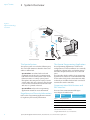
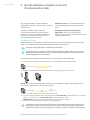
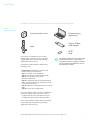
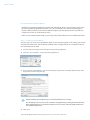
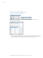
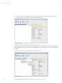
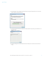
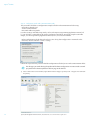
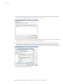
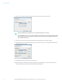
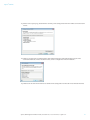
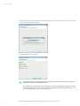
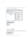
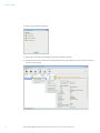
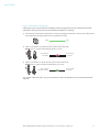
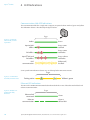
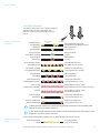
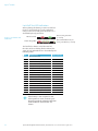
Aperio Online Quick Installation Guide ® Document No: ST-001322-E, Issue date: 30 June 2015 The global leader in door opening solutions Aperio ® Online Table of Contents 1Introduction.............................................................................................................................................. 3 Purpose..................................................................................................................................................................................3 Scope......................................................................................................................................................................................3 Applicable Products..........................................................................................................................................................3 Product Availability...........................................................................................................................................................3 Aperio Support in the EAC system...............................................................................................................................3 Abbreviations and Definitions.......................................................................................................................................3 References............................................................................................................................................................................3 2 System Overview .................................................................................................................................... 4 The Aperio System.............................................................................................................................................................4 Regulatory and Security Information.........................................................................................................................4 The Aperio Programming Application.......................................................................................................................4 Communication Hub Versions and EAC Interface.................................................................................................4 3 Quick Installation of Aperio Lock and Communication Hub................................................... 5 Automatic Pairing .............................................................................................................................................................5 Pairing with the Aperio Programming Application...............................................................................................6 Encryption Key............................................................................................................................................................................... 6 Checklist for Pairing and Configuration of Locks/sensors and Communication Hubs..................................................... 7 Preparation Before Quick Installation...................................................................................................................................... 8 Step 1 - Creating a New Installation.......................................................................................................................................... 8 Step 2 - Scanning for Communication Hubs............................................................................................................................ 9 Step 3 - Pairing Locks/sensors with Communication Hub................................................................................................... 10 Step 4 - Configuring Locks and Communication Hubs ........................................................................................................ 12 Step 5 - Apply Saved Configuration on Several Locks........................................................................................................... 17 Step 6 - Testing After Configuration........................................................................................................................................ 19 4 LED Indications.......................................................................................................................................20 Communication Hub LED Indications..................................................................................................................... 20 Ethernet LED indication................................................................................................................................................ 20 Lock LED Indications...................................................................................................................................................... 21 Lock Self Test LED Indication....................................................................................................................................... 22 5Troubleshooting ....................................................................................................................................23 During Door Installation and Update...................................................................................................................... 23 During Scanning.............................................................................................................................................................. 23 During Configuration.................................................................................................................................................... 24 During Normal Operation........................................................................................................................................... 24 2 Aperio® Online Quick Installation Guide, Document No: ST-001322-E Date: 30 June 2015 Aperio® Online 1 Introduction Purpose Applicable Products The manual is intended for installation personnel, project managers and people with similar responsibilities. Product Availability The main purpose of this manual is to provide necessary information for a quick installation of Aperio Online based products using the Aperio Programming Application. Scope This quick installation guide covers a standard installation of a complete Aperio online system including communication hubs and locks/ sensors. For a complete description of all functionality and possible settings in an Aperio online installation, refer to the Aperio Programming Application Manual, ref [1]. This manual is applicable to version 13.1 of the Aperio Programming Application. This manual can be used for AH15/20/30 communication hubs. For AH40 communication hub, refer to the Aperio Programming Application Manual, ref [1]. The products included in this manual may not be available on all markets. Please check your local ASSA ABLOY company for details. Aperio Support in the EAC system Note that the Aperio support may vary depending on the Aperio communication hub used and the level of integration. Please contact your OEM for details. Abbreviations and Definitions Abbreviation OEM EAC DIP RFID V3 1-S 1-1 Definition Original Equipment Manufacturer. A company offering Aperio support in their products. Electronic Access Control. The system controlling access decisions. Dual in-line Package. A manual electric switch used for settings on the communication hub. Radio Frequency Identification. The credential technology used. Generation 3 of the Aperio platform. One-to-several. Defines a communication hub paired with several locks/ sensors, which allows for an address range of 1-15. One-to-one. Defines a communication hub paired with one lock/sensor, which allows for an address range of 1-31. References [1] [2] ST-001321-Aperio Programming Application Manual ST-001323-Aperio Online Mechanical Installation Manual Aperio® Online Quick Installation Guide, Document No: ST-001322-E Date: 30 June 2015 3 Aperio ® Online 2 System Overview Figure 1. Aperio technology overview Programming Application IEEE802.15.4 (2.4GHz) Communication Hub RS-485, Wiegand or Ethernet Offline updater USB RFID card Aperio® OFFLINE EAC system (Electronic Access Control) RFID card Aperio® ONLINE The Aperio System The Aperio system is used in the following way: The user holds an RFID credential in front of an online or offline lock. ∙∙ Aperio Online: An online lock sends card credentials wirelessly to the communication hub which in turn communicates with an EAC (Electronic Access Control) system (wired through RS-485, Wiegand or TCP/IP). The EAC system makes the access decision. The decision is sent via the communication hub to the lock and access is granted or denied. ∙∙ Aperio Offline: Refer to the Programming Application manual for more information. Regulatory and Security Information Refer to the Programming Application manual for regulatory and security information. The Aperio Programming Application The Programming Application is used for the configuration of a door installation. It is normally installed on a laptop and is used with an Aperio USB radio dongle connected to one of the USB ports. The USB radio dongle enables the programming application to connect to a communication hub and an online lock (via the communication hub) or directly to an offline lock. V3 locks can also be connected to with a USB cable. Communication Hub Versions and EAC Interface There are four communication hub types according to the table below: Version Interface Maximum number of locks/sensors paired AH15 Wiegand/RS 485* 1 AH20 Wiegand (Adv./Std) 1 AH30 RS-485 8 AH40 IP (Ethernet) 8/16 * The firmware type loaded into the communication hub controls what interface is enabled. ** Applicable for release 3.0.0 and onwards. 4 Aperio® Online Quick Installation Guide, Document No: ST-001322-E Date: 30 June 2015 Aperio® Online 3 Quick Installation of Aperio Lock and Communication Hub This chapter describes a quick installation, applicable for most EAC systems using a standard configuration. ∙∙ Automatic pairing – The communication hub A quick installation of Aperio lock and communication hub starts with pairing the hardware. In some cases lock/communication hub are pre-paired from the factory. If not, pairing can be done in two ways: ∙∙ Pairing with the Aperio Programming automatically pairs with nearby Aperio lock/ sensor. Application – This is the recommended method, where detailed settings and encrypted communication are set. Automatic Pairing Automatic pairing is enabled by setting the DIP switch on the communciation hub in pairing mode (refer to the Mechanical installation manual/communication hub manual). Automatic pairing will only be made with unpaired locks. Communication hub and locks may be sold pre-paired from factory. If this is the case, the following pairing procedure is not necessary. However, configuration using the Aperio Programming Application is still needed. To perform pairing with communication hubs set in pairing mode, do the following: 1) Power cycle the communication hub if necessary and check that the LED is constant yellow. Pairing active Yellow 2) Hold the credential in front of the lock to activate it, or engage the magnet for the sensor. Result: The communication hub pairs with lock/sensor and indicates with one green flash. Repeat this step for each lock/sensor that should be paired. Pairing succeded Yellow + one green flash 3) After successful pairing, power off the communication hub. 4) Deactivate pairing mode and set the desired EAC address: AH15/30 RS485: Set the DIP switch 1-5 to desired address: 1-15/16-31 (1-S/1-1). AH15/20 Wiegand: Set the DIP switch 5 to OFF. AH40 Ethernet: Move the pairing mode jumper to the right position or remove it. 5) Power the communication hub to start up for normal operation. Locks/sensors and communication hubs that are automatically paired will communicate in Manufacturer mode. It is required to activate Customer mode by using the Programming Application when finalizing, according to next section, to obtain encrypted communication. Aperio® Online Quick Installation Guide, Document No: ST-001322-E Date: 30 June 2015 5 Aperio ® Online Pairing with the Aperio Programming Application The Programming Application enables connection between communication hubs and locks/sensors by pairing the devices. The communication is encrypted with a customer key, obtained from your ASSA ABLOY supplier. Using the Programming Application also allows you to access advanced settings during the pairing process of locks/sensors and communication hubs. To communicate with communication hubs and locks/sensors through the Programming Application, you also need a USB radio dongle. For installation of the Programming Application and the USB radio dongle, refer to the Aperio Programming Application manual, ref [1]. Encryption Key To obtain secure communication between communication hubs and locks/sensors an encryption key is used. This encryption key should be handled with the same care as the master mey in a traditional master key system. A person with access to the Encryption key can gain unauthorized access to any Aperio door in the system. Once loaded into the Programming Application, it will be stored encrypted in a local database and any copy should be erased from the hard drive or e-mail. It is however recommended that a copy of the encryption key is stored in a safe. The encryption key file is delivered from your local ASSA ABLOY company and should be requested on a customer/site basis. Proper handling of encryption keys is essential to lock/sensor security! It is absolutely necessary to use the customer encryption key by setting all communication hubs and locks/sensors in Customer mode to ensure a secure and encrypted communication with the lock/sensor. 6 Aperio® Online Quick Installation Guide, Document No: ST-001322-E Date: 30 June 2015 Aperio® Online Checklist for Pairing and Configuration of Locks/sensors and Communication Hubs Figure 1. Equipment needed Communication hub Programming application Tritech TriBee USB dongle Lock RFID card For V3 locks, a USB cable can be used for configuration, instead of using a USB radio dongle. Refer to the Aperio Programming Application manual, ref [1]. A complete quick installation includes the following steps: The quick installation process does NOT require that the EAC is connected to the Aperio hardware. Quick installation can be performed on hardware not yet mechanically installed. ∙∙ Preparation: Installation of software and powering the Aperio hardware. ∙∙ Step 1: Creating a new installation ∙∙ Step 2: Scanning for communication hubs ∙∙ Step 3: Pairing locks/sensors with communication hub ∙∙ Step 4: Configuring locks and communication hubs: Setting security mode, addressing mode, override credentials etc. ∙∙ Step 5: Applying saved configuration on several locks ∙∙ Step 6: Testing after configuration For some configurations a number of additional advanced settings can be necessary, such as: ∙∙ Configuration of status and alarm messages, ∙∙ Configuration of the radio communication. These and a number of other advanced settings are described in the Aperio Programming Application manual, ref [1]. Aperio® Online Quick Installation Guide, Document No: ST-001322-E Date: 30 June 2015 7 Aperio ® Online Preparation Before Quick Installation ∙∙ Install the Programming Application and the USB radio dongle drivers on your laptop. Refer to the Aperio Programming Application manual, ref [1] for instructions. The software and encryption key file is delivered from your local ASSA ABLOY company (The encryption key file is provided via encrypted e-mail or on a USB memory stick.). ∙∙ Make sure the communication hub is powered (8-24V) and that batteries are installed in the locks. Step 1 - Creating a New Installation The first step is to create a new installation, which is a password protected set of settings you need to communicate with a lock. The installation is linked to the encryption file that is needed in order for the communication to work. 1) Insert the USB radio dongle and start the Aperio Programming Application. 2) Select File – New installation... in the Programming Application. 3) Enter a name for the installation, a password matching the requirements and finally click the button in the Key file field to add the Encryption key. Proper handling of encryption keys is essential to lock/sensor security! It is absolutely necessary to use the customer encryption key by setting all communication hubs and locks/sensors in Customer mode to ensure a secure and encrypted communication with the lock/sensor. 4) Click Create. 8 Aperio® Online Quick Installation Guide, Document No: ST-001322-E Date: 30 June 2015 Aperio® Online Step 2 - Scanning for Communication Hubs Follow these steps to scan for communication hubs: 1) Click Quick Scan to find communication hubs. Result: All communication hubs within reach of the USB radio dongle of your computer are displayed in the scan result table. 2) Locate a communication hub by the last four characters of the communication hub MAC address (ex. 01CF) in the scan result table. The same characters should be on a label on the cover of the communication hub. Click Rescan if the communication hubs that you want to configure are not shown in the list. Aperio® Online Quick Installation Guide, Document No: ST-001322-E Date: 30 June 2015 9 Aperio ® Online 3) Select the communication hub(s) that you want to include in your installation. Click Show details in the window above to view detailed information in the installation view: Step 3 - Pairing Locks/sensors with Communication Hub AH30 version of the communication hub can be paired with a combination of up to 8 locks/sensors. AH15/AH20 can manage one lock/sensor and AH40 up to 16 locks/sensors (From release 3.0.0 and onwards). 1) Right click and select Communication Hub - Pair with lock or sensor. 10 Aperio® Online Quick Installation Guide, Document No: ST-001322-E Date: 30 June 2015 Aperio® Online 2) The pairing process starts. Hold the credential at the lock, or engage the magnet for the sensor to pair the hardware with the communication hub. 3) When the communication hub has indicated successful pairing with a green flash, you can click Done to see the pairing result. Result: The result is displayed. 4) Repeat this pairing process for all communication hubs and locks/sensors within reach of the USB radio dongle. Aperio® Online Quick Installation Guide, Document No: ST-001322-E Date: 30 June 2015 11 Aperio ® Online Step 4 - Configuring Locks and Communication Hubs This procedure describes a configuration example of locks and communication hubs using: ∙∙ Override credential card. ∙∙ Secure communication. ∙∙ DIP switch addressing mode. For other settings and addressing modes, refer to the Aperio Programming Application manual, ref [1]. For V3 locks, a USB cable can be used to configure paired locks instead of using the USB radio dongle, see the Programming Application Manual, ref 1, for correct installation. ∙∙ Before configuration, check that Update device time during door configuration is activated. In the menu bar, select Installation - Online - Settings... Follow the steps below to perform a default configuration of locks/sensors and communication hubs: The changes you make during the update of the door configuration are not carried out until you perform the device update on the last page in the wizard. 1) Select a lock in the scan result table, right click and select Configure (or Lock/sensor - Configure if several locks are paired). 12 Aperio® Online Quick Installation Guide, Document No: ST-001322-E Date: 30 June 2015 Aperio® Online 2) On the RFID Configuration page, click Next without any changes. (iCLASS RFID format is also supported by the Programming Application. However, no settings are necessary.) 3) If advanced mode is activated the Keypad configuration, RFID search order and Escape and return configuration pages will appear. Leave these pages without changes by clicking Next. 4) On the Override Credential page it is recommended to add a credential. Select the credential type in the drop down list and click Add and enter credential information (MIFARE Classic UID is used as an example below). This credential is used to gain access through all doors when the EAC is offline. Click OK to continue. 5) Click Next in the Wizard main window. Aperio® Online Quick Installation Guide, Document No: ST-001322-E Date: 30 June 2015 13 Aperio ® Online 6) On the Security mode Setting page, click Change to switch to Customer mode in the lock. Proper handling of encryption keys is essential to lock/sensor security! It is absolutely necessary to use the customer encryption key by setting all communication hubs and locks/sensors in Customer mode to ensure a secure and encrypted communication with the lock/sensor. 7) Select Switch to customer mode in device, click OK and then Next in the wizard main window. 8) On the Electronic Access Controller Settings page, in the Enable EAC Address via Dip Switch field, click Change and select Enable Dip Switch. 9) Click OK followed by Next in the wizard main window. 10)If advanced mode is activated the Advanced Settings, Advanced Lock/Sensor Settings and Advanced Device Settings will appear. Leave all pages without changes by clicking Next. 14 Aperio® Online Quick Installation Guide, Document No: ST-001322-E Date: 30 June 2015 Aperio® Online 11)On the Device Update page, check that the summary of the configuration tasks that will be sent to the lock is correct. 12)Click Save configuration to facilitate further lock configurations (for other hubs/locks) using the same communication hub. Unselect Enable DIP switch, enter a configuration name and click OK. 13)Click Next in the wizard main window to download the configuration to the lock and communication hub. Aperio® Online Quick Installation Guide, Document No: ST-001322-E Date: 30 June 2015 15 Aperio ® Online 14)If necessary hold a credential in front of the lock to activate the radio. (This step is not necessary for V3 locks that are connected with a USB cable.) 15)After successful update, click Close. Using the wizard for a communication hub with only one lock paired, customer mode is set both for the lock and communication hub. For communication hubs with several locks paired a warning indication will appear stating a security mode conflict. In this case, proceed the installation according to section "Step 5 - Apply saved configuration on several locks" on page 17. 16 Aperio® Online Quick Installation Guide, Document No: ST-001322-E Date: 30 June 2015 Aperio® Online Step 5 - Apply Saved Configuration on Several Locks If you have more than one lock that will use the same configuration you can apply the previously saved configuration on any lock in your installation. 1) Right click on a lock and select Apply configuration – [your configuration] 2) Confirm the update by clicking Confirm. 3) Hold a credential in front of the lock/sensor to download the configuration (This step is not necessary for V3 locks that are connected with a USB cable, or that have the polling interval set to less than 15 seconds.) Aperio® Online Quick Installation Guide, Document No: ST-001322-E Date: 30 June 2015 17 Aperio ® Online 4) After successful update, click Close. 5) Repeat the configuration for all locks paired to the communication hub. 6) Finally activate customer mode for the communication on the right click menu, select Communication hub Switch to customer mode. 18 Aperio® Online Quick Installation Guide, Document No: ST-001322-E Date: 30 June 2015 Aperio® Online Step 6 - Testing After Configuration Follow these steps to test that the installation and first configuration of each communication hub and lock has been performed correctly and that the hardware is working: 1) Check that the communication hub LED has a steady green light (if connected to an EAC). This indicates that the installation and configuration have been performed correctly. Online Green 2) Hold a credential that is invalid in the EAC system in front of the lock. Result: Access is denied and the lock LED flashes red once. Access denied, EAC online One red flash (1 second) 3) Hold a credential that is valid in the EAC system in front of the lock. Result: Access is granted and the lock LED flashes green once. Access granted, EAC offline or online One green flash (1 second) See section "4 LED Indications" on page 20 for details on the LED indications for communication hub and lock. Aperio® Online Quick Installation Guide, Document No: ST-001322-E Date: 30 June 2015 19 Aperio ® Online 4 LED Indications Communication Hub LED Indications The communication hub has a single LED. It supports an optical scheme with red, green and yellow. The indication scheme is described by the figures below: 2 sec. Figure 2. Communi- cation hub, normal operation Online Green Aperio® lock offline Green + one red flash EAC offline Green + two red flashes Aperio® lock and EAC offline Green + three red flashes UHF communication Yellow + off, fast flash Some special LED indication schemes are used during lock maintenance actions: 2 sec. Figure 3. Communica- tion hub, maintenance Pairing active Yellow + green Ethernet LED indication The LED on the AH40 communication hub indicates both the status of the Ethernet link level and ethernet communication: 2 sec. Figure 4. AH40 Com- munication hub, Ethernet Ethernet link connected Ethernet communication 20 Green Green + off fast flash Aperio® Online Quick Installation Guide, Document No: ST-001322-E Date: 30 June 2015 Aperio® Online Lock LED Indications The lock has three LEDs. They support an optical scheme with red, yellow and green. The indication scheme is described by the figures below: Figure 5. Lock, normal operation Card+PIN access (configurable) Card access (configurable) Access granted, EAC offline or online Access denied, EAC online Force closed in remote open/office mode Busy blink, com hub busy with other locks Access denied, EAC offline EAC response time Enter PIN One yellow flash after card, two flashes before PIN (0.125 sec.) One yellow flash (.25 second) One green flash (1 sec.) One red flash (1 sec.) Five yellow flashes and one red flash (.25 second) Continuous yellow flashes (.25 seconds every second) Three red flashes (.5 second each) Lock mechanism is blocked when closing1) Continuous red flashes (.125 seconds every 1 sec.) Error in lock, maintenance required2) Ten red flashes (.125 sec. each) (Repeated every 10 sec. if lock can’t close) Tamper Ten red flashes (.125 sec. each) repeated every 10 sec. Time to replace the battery Continuous yellow flashes (.25 seconds every 5 sec.) Battery reached end of life, lock disabled Continuous red flashes (.25 seconds every 5 sec.) 1) When the lock mechanism is blocked (lock jammed) the knob must be turned/handle released, to release the lock mechanism. 2) The “Error in lock” indication is also shown instead of the POST flashes if the battery is not accepted as new after a power-on-reset. Figure 6. Lock, mainte- nance Some special LED indication schemes are used during lock maintenance actions: Enter configuration mode Five yellow flashes (.125 second each) Aperio® Online Quick Installation Guide, Document No: ST-001322-E Date: 30 June 2015 21 Aperio ® Online Lock Self Test LED Indication After replacing the battery, a Power on Self Test (POST) is performed. The result is indicated using a series of red and green LED flashes as is described by the figure below: One red, one green flash (1 second) POST Successful Figure 7. Lock POST LED indication Failure during POST ... One red flash followed by 16 red or green flashes (.5 second) The first flash is always red. If the POST fail, the color of the 16 trailing flashes indicate the status of each individual test as described by the following table: Blink 1 Meaning if red POST initiation flash Code in event log - 2 Main board firmware corrupt 0x0001 3 Override list corrupt 0x0002 4 Production data corrupt 0x0004 5 Security data corrupt 0x0008 6 Configuration data corrupt 0x0010 7 Load Circuit Error 0x0020 8 Configuration data corrupt 2 0x0040 9 Secure Area Encryption Key error 0x0080 10 Secure Area Motor error 0x0100 11 Secure area communication error 0x0200 12 Secure area memory corrupt 0x0400 13 Secure area sensor or motor error 0x0800 14 Radio modem communication error 0x1000 15 Radio modem memory corrupt 0x2000 16 Radio modem configuration error 0x4000 17 Radio modem RF circuit error 0x8000 If the battery is not accepted as new after a power on reset, no POST is performed, instead the 10 quick red flashes used to indicate “Error in lock” are shown. 22 Aperio® Online Quick Installation Guide, Document No: ST-001322-E Date: 30 June 2015 Aperio® Online 5 Troubleshooting The tables below show possible problems when using the Aperio technology, and how to solve them: During Door Installation and Update Problem indication Not possible to pair communication hub and lock/sensor. Not possible to use override credentials. Cause ∙∙ Use a credential that is not on the override ∙∙ The lock/sensor and the hub are on ∙∙ Check the radio channel settings for the lock/sensor No default override credentials are configured for the installation. Add the credentials in the door configuration wizard. configured as an override credential. different radio channels. ∙∙ You have not shown the credential to the lock within 15 seconds The device update fails. Action ∙∙ You are using a credential ∙∙ The lock and hub might be in credentials list. and the hub so that they match. ∙∙ Perform device update again and show the credential to the lock within 15 seconds. different security modes, then ∙∙ Change security mode in the hub and perform communication problems can easily device update again. . occur. During Scanning Problem indication None or only some of the communication hubs are found when scanning. Cause ∙∙ All radio channels are busy or too many communication hubs are using the same channel. ∙∙ The communication hub is not working. ∙∙ The communication hub(s) are out of range. ∙∙ The communication hub(s) are not powered. Action ∙∙ Repeat the scanning process by selecting Rescan. ∙∙ Restart the communication hub. ∙∙ Temporarily reduce the number of powered up Communication hubs within radio range during configuration. (After configuration, make sure that all communication hubs have stable radio communication with paired locks/sensors.) 1. Switch installation or create a new installation Communication error ∙∙ The communication hub belongs to with the correct encryption key. is displayed and no another installation and has another 2. Repeat the scanning and pairing process. configuration can be done encryption key. to the communication hub. ∙∙ A probable cause is bad radio ∙∙ Try moving the USB radio closer to the Unstable communication conditions or limited radio range. communication hub. Either by moving the laptop or between communication by using an A-A USB extension cable to distance the hub and lock/sensor even USB radio from the PC. though the MAC address is displayed at scan. [1] Aperio communication hubs are default configured to select the best channel out of three possible, if the selected channel is disturbed a new channel selection will be done automatically. Communication hubs in an Aperio system normally distribute themselves on different channels but a synchronized power up of all communication hubs may cause them to initially choose the same channel. (Note that this problem does not affect the performance of already installed and paired locks/cylinders/sensors and communication hubs, only the Programming Application scan functionality is affected) Aperio® Online Quick Installation Guide, Document No: ST-001322-E Date: 30 June 2015 23 Aperio ® Online During Configuration Problem indication The Program Application reports an update failure. The device does not support the desired configuration. The communication hub LED is flashing red twice = no connection between the EAC system and the communication hub. Cause ∙∙ The firmware on the device is outdated. ∙∙ You are trying to configure something that the device does not support. ∙∙ The communication hub is not properly connected to the IP network (AH40). ∙∙ The hub network parameters are not correctly configured (AH40). ∙∙ The ACU address, port or TLS settings are not properly configured in the communication hub (AH40). ∙∙ The ACU is not properly configured (AH40). ∙∙ The certificate used by the ACU is not supported (AH40). Action ∙∙ Check the current firmware on the device and perform an upgrade if needed. Also check the intended new configuration. ∙∙ Check that the ethernet LED is green. If not, check ethernet cable and network equipment. ∙∙ Configure the hub network parameters. ∙∙ Configure the hub EAC connection. ∙∙ Make sure that the communication settings in the EAC matches the hub EAC connection settings. ∙∙ Make sure that a valid certificate type is used. During Normal Operation Problem indication The communication hub LED is flashing red once = no connection between the lock/sensor and the communication hub. Cause Action ∙∙ The lock/sensor and communication ∙∙ Repeat the scanning process by selecting hub are not paired. ∙∙ The lock/sensor and the communication hub have different channel masks. ∙∙ The battery of the lock/sensor has run out. ∙∙ The status message intervals differ Quick Scan/Scan. ∙∙ Pair the lock/sensor and communication hub. ∙∙ Change the radio channel mask. See the Programming Application manual, ref [1]. ∙∙ Replace the battery of the lock/sensor. See the Programming Application manual, ref [1]. ∙∙ Make sure that the lock has the same or a shorter status message interval than the hub. between the hub and the lock The communication hub LED is flashing red twice = no connection between the EAC system and the communication hub. Unstable radio communication between lock/sensor and communication hub. ∙∙ The EAC address is not properly configured in the communication hub. ∙∙ The EAC system is not properly configured. ∙∙ Poor radio link quality. ∙∙ The lock/sensor and the communication hub have different channel masks. ∙∙ Configure the EAC address. Refer to the Aperio mechanical installation manual, ref [2]. ∙∙ Change the radio channel mask. See the Programming Application manual, ref [1]. ∙∙ Reposition the communcation hub closer to the lock/sensor. ∙∙ Connect a USB cable to open the door with The V3 lock LED flashes red. ∙∙ The lock has a flat battery. emergency power. ∙∙ Replace the battery. See Lock installation instructions. 24 Aperio® Online Quick Installation Guide, Document No: ST-001322-E Date: 30 June 2015 Aperio® Online Aperio® Online Quick Installation Guide, Document No: ST-001322-E Date: 30 June 2015 25 Aperio ® Online 26 Aperio® Online Quick Installation Guide, Document No: ST-001322-E Date: 30 June 2015 ASSA ABLOY is the global leader in door opening solutions, dedicated to satisfying end-user needs for security, safety and convenience assaabloy.com/aperio Contact www.assaabloy.com/aperio Wireless lock technology