1
Quantum Cascade Solutions
Passage Max.-Meuron 1-3 CH-2000 Neuchˆatel
Case Postale 1766
Switzerland
Tel: +41 32 729 95 10
Fax: +41 32 721 36 19
Datasheet for #sbcw6269 UP
Recommendations:
Please read the User Manual and have a look at the FAQ at
http://www.alpeslasers.ch/?a=142
WARNING: Operating the laser with higher current or voltage than specified in this document may cause damage and will result in loss of warranty,
unless Alpes Lasers has permitted to do so!
WARNING: Beware of the polarity of the laser. This laser has to be
powered with negative current on the laser contact (= bonding pad, corresponding to the label ”laser” on the LLH) and the positive current on the
base contact (= submount, corresponding to the label ”base” on the LLH).
To use with a power-supply ILX Lightwave LDX-3232 or equivalent.
Emission
DN
UP
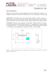
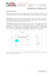
Figure 1: Support mounting for #sbcw6269 UP (please note that the laser is connected
to the UP pad drawned in blue)
1
#sbcw6269 UP
#sbcw6269 UP
10
-30C
-20C
-10C
0C
10C
9
8
7
P [mW]
6
5
4
3
2
1
0
1985 1986 1987 1988 1989 1990 1991 1992 1993 1994 1995
Frequency [cm-1]
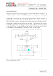
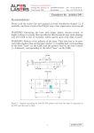
Figure 2: Output power as a function of the singlemode emission frequencies and temperatures
#sbcw6269 UP
0.48
-30C
-20C
-10C
0C
10C
0.46
0.44
I [A]
0.42
0.4
0.38
0.36
0.34
0.32
1985 1986 1987 1988 1989 1990 1991 1992 1993 1994 1995
Frequency [cm-1]
Figure 3: Applied DC current as a function of singlemode emission frequencies and temperatures
2
#sbcw6269 UP
λ[nm]
5012.5
5014
5015.5
5017.2
5018.9
5020.8
5017.4
5018.4
5019.5
5021.2
5022.9
5024
5025.2
5027
5028.7
5029.9
5034.7
5036
5022.8
ν[cm−1 ]
1995
1994.4
1993.8
1993.1
1992.5
1991.7
1993
1992.7
1992.2
1991.6
1990.9
1990.4
1990
1989.3
1988.6
1988.1
1986.2
1985.7
1990.9
P[mW]
0.2
1.3
2.8
4.7
6.9
9.2
0
0.6
1.3
2.5
0
0.7
1.5
2.7
0.2
0.8
0.1
0.9
3.9
Temp[◦ C]
-30
-30
-30
-30
-30
-30
-20
-20
-20
-20
-10
-10
-10
-10
0
0
10
10
-20
ULASER [V]
9.7
9.9
10.1
10.3
10.5
10.7
9.7
9.8
9.9
10.1
9.7
9.8
10
10.2
9.8
9.9
9.9
10
10.3
I[A]
0.32
0.35
0.38
0.41
0.44
0.47
0.34
0.36
0.38
0.41
0.37
0.39
0.41
0.44
0.4
0.42
0.43
0.45
0.44
Table 1 : singlemode optical output power as function of operating parameters
#sbcw6269 UP
power (-30C )
voltage (-30C )
power (-20C )
voltage (-20C )
power (-10C )
voltage (-10C )
power (0C )
voltage (0C )
power (10C )
voltage (10C )
Max single mode power
10
Voltage [V]
8
8
7
6
5
4
6
3
4
2
1
2
Light [mW] avg on power meter
12
0
0
0
0.05
0.1
0.15
0.2 0.25 0.3
Current [A]
0.35
0.4
0.45
-1
0.5
Figure 4: voltage and avg power vs current in continuous-wave operation (the solid squares
indicate the maximum singlemode emitted power)
3
#sbcw6269 UP
#sbcw6269 UP
10
8
Voltage [V]
9
power (-30C )
voltage (-30C )
power (-20C )
voltage (-20C )
power (-10C )
voltage (-10C )
power (0C )
voltage (0C )
power (10C )
voltage (10C )
Max single mode power
8
7
6
5
6
4
3
4
2
1
2
Light [mW] avg on power meter
12
0
0
0
0.05
0.1
0.15
0.2 0.25 0.3
Current [A]
0.35
0.4
0.45
-1
0.5
Figure 5: voltage and avg power vs current in continuous-wave operation (including the
multimode region)
Note: at -25C: Ith=315mA / Vth= 9.7V (2-wires measurements). Maximum operation
current: 0.47A for all temperatures.
4
#sbcw6269 UP
5
#sbcw6269 UP
Spectral density (normalized to 1)
-0.2
1984
0
0.2
0.4
0.6
0.8
1
1.2
10C 0.47A
1988
1990
1992
Wavenumber [cm-1]
1994
Figure 4: spectra at different temperatures for various DC currents
1986
10C 0.45A
10C 0.43A
0C 0.47A
0C 0.44A
0C 0.42A
-10C 0.47A
0C 0.4A
-10C 0.44A
-10C 0.41A
-20C 0.47A
-10C 0.39A
-10C 0.37A
-20C 0.41A
-30C 0.47A
-20C 0.38A
-30C 0.44A
-20C 0.36A
-20C 0.41A
0.34A
-30C
-30C 0.38A
-30C 0.35A
-30C 0.32A
1996
Spectral density (normalized to 1)
-30C 0.32A
-30C 0.35A
-30C 0.38A
-30C 0.41A
-30C 0.47A
1.2
-30C 0.44A
#sbcw6269 UP
1
0.8
0.6
0.4
0.2
0
-0.2
1990
1991
1992
1993
1994
Wavenumber [cm-1]
1995
1996
1997
Figure 6: spectra at -30C for various DC currents (all monomode on mode 1 up to 0.47A,
see Fig. 2 & 3)
-20C 0.34A
-20C 0.36A
-20C 0.38A
-20C 0.41A
1.2
-20C 0.44A
-20C 0.47A
#sbcw6269 UP
Spectral density (normalized to 1)
1
0.8
0.6
0.4
0.2
0
-0.2
-0.4
-0.6
-0.8
1988
1989
1990
1991
1992
Wavenumber [cm-1]
1993
1994
1995
Figure 7: spectra at -20C for various DC currents (monomode on mode 1 up to 0.44A,
then bimode, see Fig. 2 & 3)
6
#sbcw6269 UP
Spectral density (normalized to 1)
-10C 0.37A
-10C 0.39A
-10C 0.41A
-10C 0.47A
1.2
-10C 0.44A
#sbcw6269 UP
1
0.8
0.6
0.4
0.2
0
-0.2
1986
1987
1988
1989
1990
1991
Wavenumber [cm-1]
1992
1993
1994
Figure 8: spectra at -10C for various DC currents (monomode on mode 1 up to 0.44A,
then bimode, see Fig. 2 & 3)
Spectral density (normalized to 1)
0C 0.4A
0C 0.42A
0C 0.47A
1.2
0C 0.44A
#sbcw6269 UP
1
0.8
0.6
0.4
0.2
0
-0.2
1984
1985
1986
1987 1988 1989 1990
Wavenumber [cm-1]
1991
1992
1993
Figure 9: spectra at 0C for various DC currents (monomode on mode 1 up to 0.42A, then
bimode, see Fig. 2 & 3)
7
#sbcw6269 UP
Spectral density (normalized to 1)
10C 0.43A
10C 0.47A
1.2
10C 0.45A
#sbcw6269 UP
1
0.8
0.6
0.4
0.2
0
-0.2
1982
1984
1986
1988
Wavenumber [cm-1]
1990
1992
Figure 10: spectra at 10C for various DC currents (monomode on mode 1 up to 0.45A,
then bimode, see Fig. 2 & 3)
8
#sbcw6269 UP