1
Dialogic® DSI Signaling Servers
SIU Mode User Manual
www.dialogic.com
Copyright and Legal Notice
Copyright© 2004-2010 Dialogic Corporation. All Rights Reserved. You may not reproduce this document in whole or in part without permission in writing
from Dialogic Corporation at the address provided below. All contents of this document are furnished for informational use only and are subject to change
without notice and do not represent a commitment on the part of Dialogic Corporation or its subsidiaries ("Dialogic"). Reasonable effort is made to ensure the
accuracy of the information contained in the document. However, Dialogic does not warrant the accuracy of this information and cannot accept responsibility
for errors, inaccuracies or omissions that may be contained in this document.
INFORMATION IN THIS DOCUMENT IS PROVIDED IN CONNECTION WITH DIALOGIC® PRODUCTS. NO LICENSE, EXPRESS OR IMPLIED,
BY ESTOPPEL OR OTHERWISE, TO ANY INTELLECTUAL PROPERTY RIGHTS IS GRANTED BY THIS DOCUMENT. EXCEPT AS PROVIDED
IN A SIGNED AGREEMENT BETWEEN YOU AND DIALOGIC, DIALOGIC ASSUMES NO LIABILITY WHATSOEVER, AND DIALOGIC
DISCLAIMS ANY EXPRESS OR IMPLIED WARRANTY, RELATING TO SALE AND/OR USE OF DIALOGIC PRODUCTS INCLUDING LIABILITY
OR WARRANTIES RELATING TO FITNESS FOR A PARTICULAR PURPOSE, MERCHANTABILITY, OR INFRINGEMENT OF ANY
INTELLECTUAL PROPERTY RIGHT OF A THIRD PARTY.
Dialogic products are not intended for use in medical, life saving, life sustaining, critical control or safety systems, or in nuclear facility applications.
Due to differing national regulations and approval requirements, certain Dialogic products may be suitable for use only in specific countries, and thus may not
function properly in other countries. You are responsible for ensuring that your use of such products occurs only in the countries where such use is suitable.
For information on specific products, contact Dialogic corporation at the address indicated below or on the web at www.dialogic.com.
It is possible that the use or implementation of any one of the concepts, applications, or ideas described in this document, in marketing collateral produced by
or on web pages maintained by Dialogic may infringe one or more patents or other intellectual property rights owned by third parties. Dialogic does not provide
any intellectual property licenses with the sale of Dialogic products other than a license to use such product in accordance with intellectual property owned or
validly licensed by Dialogic and no such licenses are provided except pursuant to a signed agreement with Dialogic. More detailed information about such
intellectual property is available from Dialogic's legal department at 9800 Cavendish Blvd., 5th Floor, Montreal, Quebec, Canada H4M 2V9. Dialogic
encourages all users of its products to procure all necessary intellectual property licenses required to implement any concepts or applications and does
not condone or encourage any intellectual property infringement and disclaims any responsibility related thereto. These intellectual property licenses
may differ from country to country and it is the responsibility of those who develop the concepts or applications to be aware of and comply with
different national license requirements.
Dialogic, Dialogic Pro, Brooktrout, Diva, Cantata, SnowShore, Eicon, Eicon Networks, NMS Communications, NMS (stylized), Eiconcard, SIPcontrol, Diva
ISDN, TruFax, Exnet, EXS, SwitchKit, N20, Making Innovation Thrive, Connecting to Growth, Video is the New Voice, Fusion, Vision, PacketMedia,
NaturalAccess, NaturalCallControl, NaturalConference, NaturalFax and Shiva, among others as well as related logos, are either registered trademarks or
trademarks of Dialogic Corporation or its subsidiaries. Dialogic's trademarks may be used publicly only with permission from Dialogic. Such permission may
only be granted by Dialogic's legal department at 9800 Cavendish Blvd., 5th Floor, Montreal, Quebec, Canada H4M 2V9. Any authorized use of Dialogic's
trademarks will be subject to full respect of the trademark guidelines published by Dialogic from time to time and any use of Dialogic's trademarks requires
proper acknowledgement.
Windows is a registered trademarks of Microsoft Corporation in the United States and/or other countries. Other names of actual companies and products
mentioned herein are the trademarks of their respective owners.
This document discusses one or more open source products, systems and/or releases. Dialogic is not responsible for your decision to use open source in
connection with Dialogic products (including without limitation those referred to herein), nor is Dialogic responsible for any present or future effects such
usage might have, including without limitation effects on your products, your business, or your intellectual property rights.
Publication Date: November 2010
Document Number: 05-2302-010
2
Dialogic® DSI Signaling Servers SIU Mode User Manual Issue 10
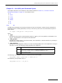
Contents
1
Overview .................................................................................................................13
1.1
General Description............................................................................................13
1.2
Related Information ...........................................................................................13
1.3
Applicability ......................................................................................................14
1.4
Hardware Overview............................................................................................14
1.4.1 Part Numbers .........................................................................................14
1.5
Signaling Overview ............................................................................................14
1.6
Functional Summary ..........................................................................................15
1.6.1 SIU Mode Overview.................................................................................15
1.6.2 Application Software ...............................................................................16
1.6.3 Fault Monitoring .....................................................................................17
1.6.4 Management Interface ............................................................................17
1.6.5 IP Security.............................................................................................17
1.6.6 Monitoring .............................................................................................17
2
Specification ............................................................................................................19
2.1
Hardware Specification .......................................................................................19
2.2
Software Licenses ..............................................................................................19
2.2.1 Software Licenses for SS7G31 and SS7G32 ................................................19
2.2.2 Software Licenses for the SS7G21 and SS7G22...........................................20
2.3
Capabilities .......................................................................................................21
2.3.1 SS7G31 and SS7G32 Signaling Servers Protocol Capabilities.........................21
3
Architecture .............................................................................................................23
3.1
Introduction ......................................................................................................23
3.2
Overview ..........................................................................................................23
3.3
Signaling Topologies...........................................................................................23
3.4
Multiple Network Support....................................................................................25
3.4.1 Support for Multiple Local Point Codes .......................................................26
3.4.2 Support for Multiple Networks ..................................................................27
3.4.3 Protocol Handling for Multiple Network Contexts .........................................28
3.5
Connection of Bearer Channels ............................................................................29
3.6
Software Environment ........................................................................................31
3.7
Communication Between SIU and Host Application .................................................31
3.8
Inter-SIU Communication ...................................................................................31
3.9
Call Control Applications .....................................................................................32
3.9.1 Standalone Operation..............................................................................32
3.9.2 Call Control Interface ..............................................................................32
3.9.3 Circuit Supervision Interface ....................................................................33
3.9.4 ISUP Detection of Failed SIU Hosts............................................................33
3.10 Transaction-Based Applications ............................................................................34
3.10.1 Management of Local SCCP Sub-Systems...................................................34
3.10.2 Sub-System In Service ............................................................................34
3.10.3 Sub-System Out of Service ......................................................................34
3.10.4 TCAP-Based Applications..........................................................................35
3.10.5 TCAP Application Interface .......................................................................35
3.10.6 Multiple TCAP Application Hosts ................................................................36
3.10.7 MAP Application Interface ........................................................................36
3.10.8 IS41 Application Interface........................................................................36
3.10.9 INAP Application Interface .......................................................................36
3.11 Resilience .........................................................................................................37
3.11.1 IP Resilience ..........................................................................................37
3.11.2 Dual Resilient Operation ..........................................................................37
3.11.3 Fault Tolerance in Call Control Applications .................................................37
3.11.4 Fault Tolerance in Transaction Processing Applications ..................................37
3
Contents
3.12
3.13
3.11.5 Use of Multiple Host Computers ................................................................37
3.11.6 Backup Host Capability ............................................................................38
Management Reporting.......................................................................................38
Alarms .............................................................................................................38
4
Licensing, Installation and Initial Configuration.......................................................39
4.1
Software Licensing .............................................................................................39
4.1.1 Purchasing Software Licenses ...................................................................39
4.1.2 Temporary Licenses.................................................................................40
4.1.3 Trial Licenses .........................................................................................40
4.2
Installing the Signaling Interface Unit ...................................................................40
4.2.1 Connecting a VT100 Terminal ...................................................................41
4.2.2 IP Configuration .....................................................................................41
4.2.3 Software Download .................................................................................42
4.2.4 Installing Software Licenses .....................................................................43
4.2.5 Configuration Procedure ..........................................................................43
5
System Management................................................................................................45
5.1
System Software ...............................................................................................45
5.1.1 Updating the Software by FTP Transfer ......................................................45
5.1.2 Updating the software from USB (SS7G31 and SS7G32 Systems)..................45
5.2
Diagnostics .......................................................................................................45
5.3
SNMP ...............................................................................................................46
5.3.1 Overview ...............................................................................................46
5.3.2 DSMI SNMP ...........................................................................................47
5.3.3 DK4032 SNMP ........................................................................................47
5.4
Alarm Listing.....................................................................................................50
5.5
Hard Disk Management ......................................................................................51
5.5.1 SS7G31 and SS7G32 Hard Disk Drive RAID Management .............................51
5.6
Secure Shell (SSH) ............................................................................................52
5.6.1 Configuring Public-Key Authentication for SSH ............................................53
5.6.2 SSH Tunneling for RSI .............................................................................53
5.6.3 Configuring the Host GCT Environment ......................................................54
5.6.4 General Notes ........................................................................................54
5.7
System Backup and Restoration...........................................................................54
5.8
SIGTRAN Throughput Licensing ...........................................................................55
6
Management Interface.............................................................................................57
6.1
Log On/Off Procedure .........................................................................................57
6.2
Command Entry ................................................................................................57
6.3
Command Responses .........................................................................................58
6.4
Automatic MMI Logging ......................................................................................58
6.5
Parameters .......................................................................................................58
6.6
Command Conventions .......................................................................................63
6.7
Commands .......................................................................................................63
6.8
Alarm Commands ..............................................................................................64
6.8.1 ALLIP – Alarm List Print ...........................................................................64
6.8.2 ALTEE – Alarm Tet End ............................................................................64
6.8.3 ALTEI – Alarm Test Initiate .......................................................................65
6.9
Configuration Commands ....................................................................................66
6.9.1 CNBOP – Configuration Board Print ...........................................................67
6.9.2 CNBUI – Configuration Backup Initiate.......................................................67
6.9.3 CNBUS – Configuration Backup Set ...........................................................68
6.9.4 CNCGP – Configuration Circuit Group Print .................................................68
6.9.5 CNCRP – Configuration MTP Route Print .....................................................68
6.9.6 CNCSP – Configuration Concerned Subsystem Print .....................................69
6.9.7 CNGAP – Configuration GTT Address Print ..................................................69
6.9.8 CNGLP – Configuration SIGTRAN Gateway List ............................................70
6.9.9 CNGPP – Configuration GTT Pattern Print ...................................................70
4
Dialogic® DSI Signaling Servers SIU Mode User Manual Issue 10
6.10
6.11
6.12
6.13
6.14
6.15
6.9.10 CNGTP – Configuration Global Title Translation Print ....................................71
6.9.11 CNLSP – Configuration MTP Linkset Print....................................................71
6.9.12 CNMLP – Configuration Monitor Link Print...................................................71
6.9.13 CNOBP – Display TRAP Configuration .........................................................72
6.9.14 CNOBS – Set TRAP Configuration ..............................................................73
6.9.15 CNPCP – Configuration PCM Print ..............................................................73
6.9.16 CNRDI – Configuration Restore Defaults Initiate..........................................74
6.9.17 CNSLP – Configuration SS7 Link Print ........................................................75
6.9.18 CNSMC – Change SNMP Manager Configuration ..........................................75
6.9.19 CNSME – End SNMP Manager Configuration................................................76
6.9.20 CNSMI – Set SNMP Manager Configuration .................................................76
6.9.21 CNSMP – Display SNMP Manager Configuration ...........................................77
6.9.22 CNSNP – Configuration SNMP Print............................................................77
6.9.23 CNSNS – Configuration SNMP Set .............................................................78
6.9.24 CNSRP – Configuration SIGTRAN Route Print ..............................................78
6.9.25 CNSTP – Configuration SIGTRAN Links Print ...............................................80
6.9.26 CNSSP – Configuration Subsystem Resource Print .......................................80
6.9.27 CNSWP – Configuration Software Print.......................................................81
6.9.28 CNSYP – Configuration System Print..........................................................82
6.9.29 CNSYS – Configuration System Set ..........................................................82
6.9.30 CNTDP – Configuration Time and Date Print ...............................................84
6.9.31 CNTDS – Configuration Time and Date Set .................................................84
6.9.32 CNTMP – Configuration Trace Mask Print ....................................................85
6.9.33 CNTMS – Configuration Trace Mask Set ......................................................86
6.9.34 CNTPE – Configuration Network Time Protocol Server End ............................87
6.9.35 CNTPI – Configuration Network Time Protocol Server Initiate ........................87
6.9.36 CNTPP – Configuration Network Time Protocol Print .....................................87
6.9.37 CNUAP – Configuration User Account Print..................................................89
6.9.38 CNUAS – Configuration User Account Set ...................................................89
6.9.39 CNUPI – Configuration Update Initiate .......................................................90
6.9.40 CNURC – Configuration Update Resource Change ........................................90
6.9.41 CNURE – Configuration Update Resource End .............................................91
6.9.42 CNURI – Configuration Update Resource Initiate .........................................91
6.9.43 CNUSC – Change SNMP v3 User Configuration ............................................92
6.9.44 CNUSE – End SNMP v3 ............................................................................92
6.9.45 CNUSI – Set SNMP v3 .............................................................................93
6.9.46 CNUSP – Display SNMP v3 .......................................................................93
IP Commands ...................................................................................................94
6.10.1 IPEPS – Set Ethernet Port Configuration.....................................................94
6.10.2 IPEPP – Display Ethernet Port Configuration ...............................................95
6.10.3 IPGWI – Internet Protocol Gateway Initiate ................................................95
6.10.4 IPGWE – Internet Protocol Gateway End ....................................................96
6.10.5 IPGWP – Internet Protocol Gateway Print ...................................................96
MML Commands ................................................................................................97
6.11.1 MMLOI – MML Log Off Initiate...................................................................97
6.11.2 MMHPP – MML Help Print .........................................................................97
Maintenance Commands .....................................................................................99
6.12.1 MNINI – Maintenance Inhibit Initiate .........................................................99
6.12.2 MNINE – Maintenance Inhibit End .............................................................99
6.12.3 MNRSI – Maintenance Restart System Initiate .......................................... 100
Measurement Commands.................................................................................. 102
6.13.1 MSEPP – Measurement Ethernet Port Print ............................................... 102
6.13.2 MSHLP – Measurement of Host Links Prints .............................................. 103
6.13.3 MSLCP – Measurement of License Capability Print ..................................... 104
6.13.4 MSMLP – Measurement Monitor link Print ................................................. 105
6.13.5 MSRLP – Measurement Remote Links Print ............................................... 106
6.13.6 MSPCP – Measurement PCM Print............................................................ 107
6.13.7 MSSLP – Measurement SS7 Link Print...................................................... 108
6.13.8 MSSTP – Measurement of SIGTRAN Links Print ......................................... 109
6.13.9 MSSYP – Measurement System Print ....................................................... 109
Reset Command .............................................................................................. 111
6.14.1 RSBOI – Reset Board Initiate.................................................................. 111
Status Commands ........................................................................................... 112
6.15.1 STALP – Status Alarm Print .................................................................... 112
6.15.2 STBOP – Status Board Print ................................................................... 113
5
Contents
6.16
6.17
7
6
6.15.3 STCGP – Status Circuit Group Print ......................................................... 113
6.15.4 STCRP – Status SS7 Route Print ............................................................. 114
6.15.5 STDDP – Status Disk Drive Print ............................................................. 115
6.15.6 STDEP – Status Device Print................................................................... 115
6.15.7 STDHP – DTS Host Status ...................................................................... 117
6.15.8 STEPP – Status Ethernet Port Print .......................................................... 118
6.15.9 STHLP – Status Host Link Print ............................................................... 118
6.15.10STIPP – Status IP Print .......................................................................... 119
6.15.11STLCP – Status Licensing Print................................................................ 120
6.15.12STMLP – Status Monitor Link Print ........................................................... 122
6.15.13STPCP – Status PCM Print ...................................................................... 122
6.15.14STRAP – Status Remote Application Server Print ....................................... 123
6.15.15STRLP – Status Remote SIU Link Print ..................................................... 124
6.15.16STSLP – Status SS7 Link Print ................................................................ 125
6.15.17STSRP – Status SIGTRAN Route Print ...................................................... 126
6.15.18STSSP – Status Sub-System Resource Print.............................................. 127
6.15.19STSTP – SIGTRAN Link Status ................................................................ 127
6.15.20STSYP – Status System Print .................................................................. 128
6.15.21STTDP – Status TCAP Dialog Print ........................................................... 129
6.15.22STTPP – Network Time Protocol Status Print ............................................. 130
6.15.23STTRP – Status TCAP Resource Print........................................................ 131
Network Time Protocol...................................................................................... 132
Command Summary ........................................................................................ 133
Configuration ......................................................................................................... 137
7.1
Overview ........................................................................................................ 137
7.1.1 Syntax Conventions .............................................................................. 137
7.1.2 Dynamic Configuration .......................................................................... 138
7.1.3 Programming Circuit Group Configuration................................................. 138
7.2
Command Sequence ........................................................................................ 138
7.3
Detection of Errors in the Configuration File......................................................... 139
7.4
SIU Commands ............................................................................................... 141
7.4.1 SIU_HOSTS – Number of Hosts .............................................................. 141
7.4.2 SIU_REM_ADDR – Other SIU Ethernet Address ......................................... 142
7.5
Physical Interface Commands ............................................................................ 143
7.5.1 SS7_BOARD – SS7 Board Configuration ................................................... 143
7.5.2 LIU_CONFIG – Line Interface Configuration .............................................. 144
7.5.3 STREAM_XCON – Cross Connect Configuration.......................................... 147
7.6
MTP Commands............................................................................................... 149
7.6.1 MTP_CONFIG – Global MTP Configuration ................................................. 149
7.6.2 MTP_NC_CONFIG – Network Context MTP Configuration............................. 150
7.6.3 MTP_LINKSET – MTP Link Set ................................................................. 152
7.6.4 MTP_LINK – MTP Signaling Link .............................................................. 153
7.6.5 MTP2_TIMER – MTP2 Timer Configuration ................................................ 155
7.6.6 MTP3_TIMER – MTP3 Timer Configuration ................................................ 156
7.6.7 MTP_ROUTE – MTP Route....................................................................... 157
7.6.8 MTP_USER_PART – MTP User Part ........................................................... 159
7.6.9 MONITOR_LINK – Monitor Link ............................................................... 160
7.7
SIGTRAN Configuration Commands .................................................................... 162
7.7.1 STN_LAS – SIGTRAN Local Application Server Configuration ....................... 162
7.7.2 STN_LBIND – SIGTRAN Local Bind Configuration....................................... 163
7.7.3 STN_LINK – SIGTRAN Link Configuration ................................................. 163
7.7.4 STN_NC – SIGTRAN Network Context ...................................................... 165
7.7.5 STN_RAS – SIGTRAN Remote Application Server Configuration ................... 165
7.7.6 STN_RASLIST – SIGTRAN Remote Application Server List Configuration ....... 166
7.7.7 STN_ROUTE – SIGTRAN Route Configuration ............................................ 166
7.7.8 STN_RSGLIST – SIGTRAN Route signaling Gateway List Configuration.......... 167
7.8
ISUP Configuration Commands .......................................................................... 168
7.8.1 ISUP_CONFIG – ISUP Configuration ........................................................ 168
7.8.2 ISUP_CFG_CCTGRP – ISUP Circuit Group Configuration.............................. 169
7.8.3 ISUP_TIMER – ISUP Timer Configuration.................................................. 171
7.9
SCCP Configuration Commands.......................................................................... 172
7.9.1 SCCP_CONFIG – SCCP Configuration ....................................................... 172
7.9.2 SCCP_NC_CONFIG – SCCP Network Context Configuration ......................... 173
Dialogic® DSI Signaling Servers SIU Mode User Manual Issue 10
7.10
7.11
7.12
7.13
7.14
8
7.9.3 SCCP_GTT – Global Title Translation ........................................................ 173
7.9.4 SCCP_GTT_ADDRESS – Global Title Translation Address ............................. 174
7.9.5 SCCP_GTT_PATTERN – Global Title Translation Pattern ............................... 176
7.9.6 SCCP_SSR – SCCP Sub-System Resources ............................................... 178
7.9.7 SCCP_CONC_SSR – SCCP Concerned Sub-Systems Configuration ................ 180
TCAP Configuration Commands.......................................................................... 182
7.10.1 TCAP_CONFIG – TCAP Configuration........................................................ 182
7.10.2 TCAP_NC_CONFIG – TCAP Network Context Configuration.......................... 183
7.10.3 TCAP_CFG_DGRP – TCAP Dialog Group Configuration ................................ 184
MAP Configuration Commands ........................................................................... 185
7.11.1 MAP_CONFIG – MAP Configuration .......................................................... 185
7.11.2 MAP_NC_CONFIG – MAP Configuration .................................................... 185
IS41 Configuration Commands .......................................................................... 187
INAP Configuration Commands .......................................................................... 188
7.13.1 INAP_CONFIG – INAP Configuration ........................................................ 188
7.13.2 INAP_NC_CONFIG – INAP Network Context Configuration .......................... 188
7.13.3 INAP_FE – INAP Functional Entities ......................................................... 189
7.13.4 INAP_AC – INAP Application Contexts...................................................... 189
Protocol Configuration Modification..................................................................... 191
7.14.1 Establishing an FTP Session ................................................................... 191
7.14.2 Transferring the Protocol Configuration to a Remote Computer .................... 191
Configuration Guidelines........................................................................................ 193
8.1
Overview ........................................................................................................ 193
8.2
IP Port Bonding ............................................................................................... 193
8.3
Configuring Multiple Network Contexts................................................................ 194
8.3.1 MTP .................................................................................................... 194
8.3.2 ISUP ................................................................................................... 194
8.3.3 SCCP .................................................................................................. 194
8.3.4 DTS .................................................................................................... 194
8.3.5 TCAP................................................................................................... 195
8.3.6 MAP .................................................................................................... 195
8.3.7 IS41 ................................................................................................... 195
8.3.8 INAP ................................................................................................... 195
8.3.9 Configuration Examples ......................................................................... 196
8.4
Configuring a Dual Resilient SIU System ............................................................. 199
8.5
Configuring an ANSI System ............................................................................. 199
8.6
Specifying Default Routes ................................................................................. 200
8.7
Dynamic Host Activation ................................................................................... 200
8.8
Dynamic Configuration ..................................................................................... 201
8.8.1 Config.txt-Based Dynamic Configuration .................................................. 201
8.8.2 Application-Based Dynamic Configuration................................................. 203
8.9
SIGTRAN M2PA Signaling .................................................................................. 203
8.9.1 Overview ............................................................................................. 203
8.9.2 M2PA License ....................................................................................... 203
8.9.3 SS7 over M2PA..................................................................................... 204
8.9.4 Configuration Examples ......................................................................... 204
8.10 SIGTRAN M3UA Signaling ................................................................................. 204
8.10.1 Overview ............................................................................................. 204
8.10.2 Configuration Examples ......................................................................... 205
8.11 SIGTRAN M3UA - Dual Operation ....................................................................... 206
8.12 Simultaneous MAP/INAP/IS41 Operations ........................................................... 206
8.13 GTT Configuration ............................................................................................ 207
8.13.1 How to configure GTT ............................................................................ 207
8.13.2 Global Title Address Information ............................................................. 207
8.13.3 Examples............................................................................................. 208
8.14 HSL Signaling.................................................................................................. 211
8.14.1 LIU_CONFIG ........................................................................................ 211
7
Contents
8.15
8.16
8.14.2 MTP_LINK <interface_mode>................................................................. 211
8.14.3 MTP_LINK <flags>................................................................................ 212
8.14.4 MTP_LINK <timeslot> ........................................................................... 212
8.14.5 MTP_LINK <blink>................................................................................ 212
ATM Signaling ................................................................................................. 212
Monitoring ...................................................................................................... 212
9
Host Software ........................................................................................................ 215
9.1
Introduction .................................................................................................... 215
9.2
Application Programming Interface..................................................................... 215
9.2.1 Sending a Message to an SIU ................................................................. 215
9.2.2 Receiving Messages From an SIU ............................................................ 216
9.2.3 Requesting a Confirmation ..................................................................... 216
9.2.4 Congestion Management........................................................................ 216
9.3
Contents of the SS7 Development Package.......................................................... 217
9.4
Software Installation for Windows®. ................................................................... 217
9.4.1 Installing the Development Package for Windows®. ................................... 218
9.4.2 Removing the Development Package for Windows®. .................................. 219
9.5
Software Installation for Linux ........................................................................... 219
9.5.1 Installing the Development Package for Linux ........................................... 219
9.5.2 Support for Larger Message Queues ........................................................ 220
9.5.3 Removing the Development Package for Linux .......................................... 220
9.6
Software Installation for Solaris ......................................................................... 220
9.6.1 Installing the Development Package ........................................................ 220
9.6.2 Removing the Development Package ....................................................... 221
9.7
Example Application Programs ........................................................................... 221
9.8
Host Link Operation ......................................................................................... 222
9.9
Application Operation ....................................................................................... 222
9.9.1 Starting the Host Software ..................................................................... 224
9.9.2 Startup Order and Congestion Control ..................................................... 224
9.9.3 Shutting Down a Host ........................................................................... 225
10
Application Programming Interface ....................................................................... 227
10.1 API Commands................................................................................................ 227
10.1.1 API_MSG_COMMAND – User Command Request........................................ 227
10.1.2 RSI_MSG_CONFIG – RSI Link Configuration Request ................................. 230
10.1.3 RSI_MSG_UPLINK – RSI Link Activate Request ......................................... 232
10.1.4 RSI_MSG_LNK_STATUS – RSI Link Status Indication ................................. 232
10.1.5 MVD_MSG_LIU_STATUS – PCM Trunk Status Indication .............................. 233
10.1.6 MGT_MSG_SS7_STATE – SS7 Level 2 Status Indication.............................. 234
10.1.7 MTP_MSG_MTP_EVENT – MTP Protocol Event Indication ............................. 234
10.1.8 API_MSG_USER_EVENT – User Event Indication........................................ 235
10.1.9 API_MSG_SIU_STATUS – SIU Status Indication......................................... 236
10.1.10MGT_MSG_TRACE_EV – Trace Event Indication ......................................... 237
10.1.11CAL_MSG_HEARTBEAT – Check Heartbeat................................................ 238
11
Host
11.1
11.2
11.3
11.4
11.5
A
SIU Resilience........................................................................................................ 251
8
Utility and Command Syntax .......................................................................... 241
rsi ................................................................................................................. 241
rsicmd............................................................................................................ 242
s7_log ........................................................................................................... 242
s7_play .......................................................................................................... 244
gctload........................................................................................................... 246
11.5.1 System Status (gctload -t1) ................................................................... 247
11.5.2 Show All Currently Allocated API messages (gctload -t2) ............................ 247
11.5.3 Running gctload as a Service.................................................................. 248
11.6 tim ................................................................................................................ 250
11.7 tick ................................................................................................................ 250
Dialogic® DSI Signaling Servers SIU Mode User Manual Issue 10
A.1
A.2
A.3
A.4
A.5
A.6
B
Introduction .................................................................................................... 251
Overview of SIU Operation ................................................................................ 251
A.2.1 Circuit-Switched API Operation ............................................................... 253
A.2.2 Transaction-Based API Operation ............................................................ 253
A.2.3 Management Interface .......................................................................... 253
Potential Points of Failure .................................................................................. 253
A.3.1 Failure of SS7 Links .............................................................................. 253
A.3.2 Failure of SS7 Routes ............................................................................ 254
A.3.3 Failure of Power Supply ......................................................................... 255
A.3.4 Failure of Signaling Interface Unit ........................................................... 256
A.3.5 Failure of IP Subnetwork........................................................................ 264
A.3.6 Failure of Application ............................................................................. 265
Configuring a Dual SIU Pair ............................................................................... 266
A.4.1 Hardware Requirements ........................................................................ 267
A.4.2 System Configuration ............................................................................ 267
A.4.3 Changes to the config.txt Parameter File .................................................. 267
Run-time Operations of a Dual-resilient SIU System ............................................. 270
A.5.1 Connecting a Host to Two SIUs ............................................................... 270
A.5.2 Communicating with Both SIUA and SIUB ................................................ 270
A.5.3 Transferring Control of a Circuit Group Between SIUs................................. 271
Frequently Asked Questions .............................................................................. 274
Building SIU Systems with more than 128 Hosts.................................................... 277
B.1
Introduction .................................................................................................... 277
B.2
Overview of Host Clustering .............................................................................. 277
B.3
System Operation ............................................................................................ 279
B.3.1 Telephony API Operation........................................................................ 279
B.3.2 Programming Model .............................................................................. 280
B.3.3 Connecting a Host ................................................................................ 280
B.3.4 Clustering Host Platforms....................................................................... 281
B.3.5 Dual SIU Operation ............................................................................... 282
B.4
Configuration Parameters.................................................................................. 282
B.4.1 Circuit Group Configuration for Host Clustering ......................................... 282
B.4.2 Configuring the Master Host ................................................................... 282
B.4.3 Configuring the Slave Host..................................................................... 284
B.5
Example Configuration ..................................................................................... 285
B.6
Frequently Asked Questions .............................................................................. 288
Glossary................................................................................................................. 289
Figures
1
2
3
4
5
6
7
8
9
10
11
12
13
14
15
16
17
18
19
Structure of SIU .......................................................................................................15
Integrating the SIU...................................................................................................16
Signaling Paths in a Single SIU Configuration ...............................................................23
Signaling Paths in a Dual Resilient Configuration ...........................................................24
Single SIU Connected to SSP/SCP or STP.....................................................................24
SIU Dual Configuration with Connections to SSP/SCP ....................................................24
SIU Dual Configuration with Connections to STP ...........................................................25
SIU Dual Configuration with Connections to Mated STP Pair............................................25
Multiple Network Contexts to Support Multiple Local Point Codes.....................................26
Multiple Network Contexts with an STP Pair..................................................................26
Multiple Network Contexts Support for Multiple Network Types .......................................27
Module IDs for Use with Multiple Network Contexts .......................................................28
Signaling Separate from Data Circuits .........................................................................29
Signaling Channel Extracted by SIU ............................................................................30
Multiple Local Point Code Configuration Example ......................................................... 196
Multiple Network Configuration Example .................................................................... 197
SIU Structure......................................................................................................... 252
Integrating the SIUs ............................................................................................... 252
SIU Connected to Adjacent Node with Two Links in a Link Set....................................... 254
9
Contents
20
21
22
23
24
25
26
27
28
29
30
31
32
33
34
35
36
37
38
39
40
41
42
43
44
SIU Connected to Mated STP Pair Providing Route Resiliency ........................................ 255
Dual SIU Architecture.............................................................................................. 256
Transmit Routing to a Single Destination.................................................................... 257
Dual-resilient SIUs Connected to a Mated STP Pair in a Straight Link Configuration .......... 258
Dual-resilient SIUs Connected to a Mated STP Pair in a Crossed Link Configuration .......... 258
Transmit Routing Through Mated STPs....................................................................... 259
Normal Routing for Circuit Group 0 When Controlled by SIUA ....................................... 260
Routing When All Local Links Have Failed, Group 0 Controlled by SIUA........................... 261
Routing Following Failure of SIUA.............................................................................. 262
Two Different Architectures for a TCAP Processing SIU System...................................... 263
Message Flow on a Dual-resilient System Running the SS7 Stack up to TCAP .................. 264
Dual LAN Operation on the SIU................................................................................. 265
TCAP Dialog Groups Example ................................................................................... 266
Inter-SIU Link over Crossed T1/E1 Cable ................................................................... 267
Example Configuration to an Adjacent SSP/SCP .......................................................... 269
Example Configuration to an Adjacent STP Pair ........................................................... 270
SIU Architecture..................................................................................................... 277
Logical View of Host Clustering ................................................................................. 278
Receive Message Flow for a Two-Host System............................................................. 279
Redirecting Messages between ISUP and the Application .............................................. 280
Message Redirection in Host Clustering...................................................................... 281
Directing Messages to SIUA and SIUB ....................................................................... 282
Use of siu_id values ................................................................................................ 283
Logical View of Clustered Host System ...................................................................... 285
Physical View of a Clustered Host System .................................................................. 285
Tables
1
2
3
4
5
6
7
8
9
10
10
Library Functions for Inter Process Communications ......................................................31
Possible Alarm Events ...............................................................................................50
Command Responses ................................................................................................58
Parameter Definitions................................................................................................58
Command Summary ............................................................................................... 138
Supported Actions for Dynamic Configuration ............................................................. 202
Files Installed on a System Running Windows®........................................................... 218
Files Installed on a System Running Linux.................................................................. 219
Files Installed on a System Running Solaris................................................................ 221
Comparison of a Straight Link Configuration vs. Crossed Link Configuration.................... 259
Dialogic® DSI Signaling Servers SIU Mode User Manual Issue 10
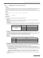
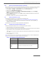
Revision History
Date
Part Number
Issue No.
September 2010
05-2302-010
10
November 2009
05-2202-009
Description
Updated to reflect Release 2.2.0 of the software, which introduces
mode-specific software distributions, additional configuration,
measurement, status MMI commands, and enhanced diagnotics and
logging.
9
Updated to reflect V2.14 of the software which introduces support for
the Dialogic® SS7MD Network Interface Board, the ability to distribute
traffic from MAP, INAP and IS41 modules on the SIU to applications on
multiple hosts.
This issue also increases the number of SIU hosts supported by the
SIU to 128, allows the simultaneous configuration and operation of
MAP, INAP and TCAP on the SIU and enhances the configuration
options for M3UA and M2PA on the SIU.
January 2009
05-2302-008
8
Updated to reflect V2.00 of the software which introduces support for
high-performance MTP link monitoring, extends SIU dynamic
configuration, introduces built-in real-time logging to disk for tracing,
events and errors as well as providing additional enhancements
relating to increased SSR resources, SSR status reporting and
management host configuration.
August 2008
05-2302-007
7
Updated to include requirements of Dialogic® DSI SS7G31 and
SS7G32 Signaling Servers.
June 2008
05-2302-007-01
7-01
March 2008
05-2302-006
6
Updated to reflect V5.0 software which supports M3UA, M2PA, BICC,
TUP, ISUP 2000, STDEP, Trial License, Throughput License, Temporary
License, System Archive, Diagnostic Software, Network Time Protocol
support, SNMP alarms and status, GTT configuration.
September 2007
05-2302-005
5
Updates for brand changes, web sites, and other minor corrections.
December 2005
05-2302-004
4
Minor updates and corrections.
October 2005
05-2302-003
3
Updated to include support for multiple networks (including multiple
local point codes) and resilient IP connectivity.
2
Updated to reflect V2.xx software which supports DSC and SGW mode
in addition to SIU mode.
Addition of programmatic (message-based) circuit group
configuration, ability to configure backup hosts and new STDHP, IPEPS
and IPEPP commands.
New ANNEX describing SIU resilience and minor clarifications
throughout.
August 2005
05-2302-002
Trial release version. Updated to include requirements of Dialogic®
DSI SS7G31 and SS7G32 Signaling Servers.
December 2004
05-2302-001
1
Updates to support initial release.
October 2004
05-2302-001-01
A
Initial draft to support Field Trial release.
Note: The current release of this guide can be found at:
http://www.dialogic.com/support/helpweb/signaling
11
Contents
12
Dialogic® DSI Signaling Servers SIU Mode User Manual Issue 10
Chapter 1: Overview
1.1
General Description
This manual is applicable to the Dialogic® SS7G31 and SS7G32 Signaling Servers.
Note: Throughout this manual, these products are referred to collectively as the Dialogic® DSI
Signaling Servers or as the Signaling Servers; or individually, by their particular alphanumeric
designation (SS7G31 or SS7G32). In addition, the SS7G31 and SS7G32 models may be referred
to collectively as “SS7G3x”. In addition, unless otherwise stated, text within this document is
applicable to all servers within the Dialogic® DSI SS7 Signaling Server range when operating in
SIU mode, and the terms “SIU” and Signaling Interface Unit” may be used to refer to a Dialogic®
DSI Signaling Server being operated in SIU mode or as an SIU.
The Signaling Interface Unit (SIU) provides an interface to SS7 networks for a number of distributed
application platforms via TCP/IP LAN. In this mode, the units implement the SS7 Message Transfer Part
(MTP) and a number of User Parts (ISUP, BICC, TUP, SCCP, TCAP, MAP, IS41 and INAP). In addition, when
fitted with Dialogic® DSI SS7 Boards, the SIU can be used to build high performance monitoring
applications.
The Signaling Server may be purchased as one of two equipment types: SS7G31 and SS7G32. The servers
use the same software, but use different chassis and different signaling boards. See Section 1.4, “Hardware
Overview” on page 14 for a fuller description of the Signaling Server hardware.
The SS7G31 and SS7G32 Signaling Servers are shipped in TEST Mode - without any operation mode license
installed. To enable SIU functionality, order either a SS7SBG30SIUV,SS7SBG30SIUU, SS7SBG30SIUL, or
SS7SBG30SIUJ license. See Section 5.2, “Diagnostics” on page 45 for more information about the available
licenses as well as their purchase, installation, and operation.
A Signaling Server with the SGW Mode software license installed and enabled, operates as a SIGTRAN
Signaling Gateway (hereinafter sometimes referred to as "Signaling Gateway"), offering support for the
M3UA and M2PA SIGTRAN protocols. Description and use of the system acting as a SIGTRAN Signaling
Gateway is outside the scope of this manual. See the SGW Mode User Manual for a detailed description of
this mode of operation.
1.2
Related Information
Refer to the following for related information:
•
•
•
•
•
•
Dialogic® DSI SS7G31 and SS7G32 Signaling Servers Hardware Manual (05-2630)
Dialogic® SS7G2x Signaling Server SIU Mode Migration Guide (05-2303)
Dialogic® DSI Signaling Servers SGW Mode User Manual (05-2304)
Dialogic® SS7 Protocols Software Environment Programmer’s Manual (U10SSS)
Dialogic® DSI Signaling Servers SNMP User Manual (U05EPP)
Dialogic® DSI Signaling Servers User Manual Supplement for ATM Operation (U01LFD)
The current software and documentation supporting Dialogic® DSI Signaling Server products is available on
the web at:http://www.dialogic.com/support/helpweb/signaling/.
The product data sheet is available at:http://www.dialogic.com/support/helpweb/signaling/.
For more information about Dialogic® SS7 products and solutions, visit:http://www.dialogic.com/support/
helpweb/signaling/.
The following manuals should be read depending on the protocol options installed on the SIU:
•
•
•
•
ISUP Programmer’s Manual (U04SSS)
SCCP Programmer’s Manual (U05SSS)
TCAP Programmer’s Manual (U06SSS)
MAP Programmer’s Manual (U14SSS)
13
Chapter 1 Overview
•
•
•
•
•
•
1.3
IS41 Programmer’s Manual (U17SSS)
TUP Programmer's Manual (U09SSS)
INAP Programmer’s Manual (U16SSS)
SCTP Programmer’s Manual (U01STN)
M3UA Programmer’s Manual (U02STN)
M2PA Programmer’s Manual (U03STN)
Applicability
This manual is applicable to SS7G31 and SS7G32 with Release 2.2.0.
This manual is not applicable if operating as a SIGTRAN Signaling Gateway. See the SGW Mode User Manual
for this mode of operation.
1.4
Hardware Overview
The Signaling Server may be purchased as one of the following equipment types:
•
An SS7G31 is a 1U Signaling Server and may be purchased with one Dialogic® DSI SPCI4 Network
Interface Board, (with 4 SS7 links and 4 T1/E1 interfaces), or one Dialogic® DSI SS7HDP Network
Interface Board, (with 64 SS7 links and 4 T1/E1 interfaces or 2 HSL links).
•
An SS7G32 is a 2U Signaling Server and may be purchased with one, two or three Dialogic® DSI SS7HDP
Network Interface Boards (with 64 links and 4 T1/E1 interfaces per board or 2 HSL links per board) with
a system maximum of 192 LSL SS7 links or 6 HSL SS7 links.
Note: The SS7G32 also supports the installation in the field of up to 2 Dialogic® SS7MD Network
Interface Boards. These SS7MD boards may be used for termination and monitoring of ATM
signaling links. SS7MD boards cannot be installed in an SS7G31 or SS7G2x Signaling Server.
When using two SS7MD boards, the maximum link density for the SS7G32 is increased to 248
low speed or 8 high speed signaling links, which can be either ATM or Q.703 Annex A. See the
Signaling Servers User Manual Supplement for ATM Operation for further information regarding
the installation and operation of SS7MD signaling boards.
When T1 or E1 is selected, the Signaling Server may be configured to pass the bearer channels from one
PCM port to another, effectively “dropping out” the signaling in line.
The SS7G31 and SS7G32 support two hard disks configured as a RAID 1 array. See Section 5.5.1, “SS7G31
and SS7G32 Hard Disk Drive RAID Management” on page 51 for details.
See Chapter 2, “Specification” for a definition of the capabilities of the system.
1.4.1
Part Numbers
For the SS7G31 and SS7G32 products, refer to the Dialogic® DSI SS7G31 and SS7G32 Signaling Servers
Product Data Sheet (navigate from http://www.dialogic.com/products/signalingip_ss7components/
signaling_servers_and_gateways.htm) for a list of the ordering codes and definitions of the hardware
variants of the two equipment types.
1.5
Signaling Overview
The signaling capability of the SIU depends on the number and type of signaling boards installed. Up to a
maximum of 64 link sets and 512 signaling links are supported.
All link sets terminate at an adjacent signaling point, which may be a Signaling Transfer Point (STP), allowing
the use of the quasi-associated signaling mode. When operating as a pair, resilience is provided at MTP3
through the use of a link set between the two units.
In addition to SS7 over TDM signaling, the SIU supports the SIGTRAN M2PA and M3UA protocols. A
maximum 256 M2PA or M3UA links are configurable - depending on the license installed.
14
Dialogic® DSI Signaling Servers SIU Mode User Manual Issue 10
The SIU will also allow mixed configurations deploying SS7 over TDM, SS7 over ATM, SS7 over M2PA and
SS7 over M3UA signaling. Resilience can be achieved using M2PA or M3UA links between a pair of units.
1.6
Functional Summary
1.6.1
SIU Mode Overview
The Signaling Server, when operating in SIU Mode, provides an interface to SS7 networks for a number of
distributed application platforms via TCP/IP LAN. In this mode, the unit implements a number of User Parts
(ISUP, BICC, TUP, SCCP, TCAP, MAP, IS41 and INAP) operating over either M3UA or MTP3 utilizing Low Speed
(LSL), High Speed (HSL), Asynchronous Transfer Mode (ATM), or M2PA SS7 Signaling Links.
The SIU supports multiple SS7 signaling links within the same PCM trunk interface or over multiple PCM
trunks. The SIU examines the timeslots carrying the SS7 information and processes them accordingly, then
outputs this data to the LAN using TCP/IP. Similarly, it takes commands from the TCP/IP LAN and converts
those to SS7 signals for transmission to the SS7 network.
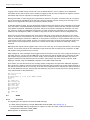
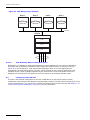
The SIU terminates the signaling and distributes the extracted information to multiple application platforms.
In the case of circuit switched telephony, these are the platforms that manage the bearer (non-signaling)
channels. Driver software manages communication between the application and the SIU.
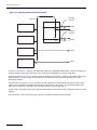
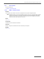
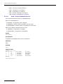
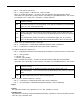
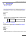
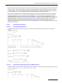
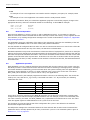
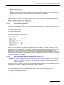
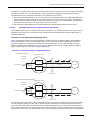
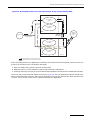
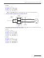
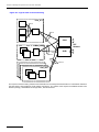
Figure 1. Structure of SIU
Application
#0
Application
#1
Application
#N
API Layer / Ethernet Driver
MAP
Configuration
and
Management
ISUP
TUP
TCAP
SCCP
MTP Levels 1 to 3
Each SIU can optionally be used as one half of a pair of units operating in a dual resilient configuration. The
two units are designated SIU A and SIU B and a single signaling point code is allocated to the SIU pair. See
Appendix A, “SIU Resilience” for more information.
For circuit-related operation, the SIU provides the ability to automatically distribute the call messaging
between a number of physically independent application platforms, thus providing a degree of fault tolerance
within the application space.
The Application Programming Interface (API) between the application and the SIU is message based. Each
command issued by the application to the SIU is packaged in a message structure and sent to the SIU using
the C-library functions and drivers provided. In the receive direction, information is conveyed to the user
application in structured messages placed in a sequential queue.
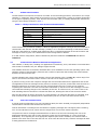
The SS7 signaling may be presented from the network multiplexed in a timeslot on a T1 (1.544 Mbps, also
known as DS1) or an E1 (2.048 Mbps) bearer.
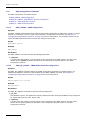
For telephony operation (using a telephony layer 4 protocol such as ISUP), if the SS7 signaling is multiplexed
onto a PCM bearer, the voice circuits may be passed transparently through the SIU to the application
platform that terminates the physical circuits.
15
Chapter 1 Overview
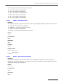
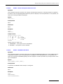
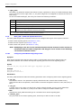
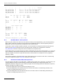
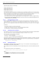
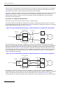
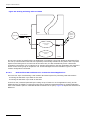
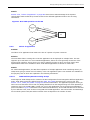
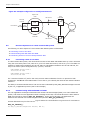
Figure 2. Integrating the SIU
T1 or E1 Trunks,
Voice Circuits
Only
CT Application Platform
SIU
T1 or E1 Trunks,
with SS7 Signaling
Channel
CT Application Platform
SS7 information
Ethernet
1.6.2
Application Software
The SIU provides an SS7 interface for applications running on remote platforms (host computers). Each
application may be implemented as a process within a multi-tasking operating system on the host computer,
or, in the case of a non multi-tasking host, as a single application task (or program). An application may be
any of the following:
•
•
•
•
•
•
•
A User Part with direct access to MTP or M3UA
A telephony application with access to the ISUP User Part
A local sub-system using SCCP (Connectionless and Connection-oriented)
A local-sub-system using TCAP (Transaction Capabilities)
A local-sub-system using MAP (Mobile Application Part)
A local-sub-system using IS41 (ANSI Mobile Application Part)
A local-sub-system using INAP (Intelligent Network Application Part)
Note: TCAP and applications above MAP, INAP and IS41 may be distributed using a Distributed
Transaction Server (DTS), allowing a highly scalable architecture. See the DTS User Guide for
further information.
This provides a flexible implementation for a number of SS7 functions such as Service Switching Point (SSP),
Service Control Point (SCP), mobile HLR and Intelligent Peripheral (IP).
Each application task is assigned a unique module identifier (module ID) and communicates with other tasks
in the system using a message based Inter-Process Communication (IPC) mechanism. The software library
that manages communication between each SIU and the host reserves five module IDs for user applications,
and a further module ID to receive management status and event indications from the SIU.
Examples of application modules and management functions are supplied in source code form for use on the
host computer.
16
Dialogic® DSI Signaling Servers SIU Mode User Manual Issue 10
1.6.3
Fault Monitoring
The SIU is able to detect internal fault conditions and report these to the user. The internal faults are
combined with external events, to provide an alarm reporting function, which has several possible interfaces
to the user, and may be local or remote. For further information on alarm functions refer to Section 3.13,
“Alarms” on page 38.
1.6.3.1
Diagnostic Log Files
The SIU is able to generate several diagnostic log files for use in the event of an unexpected system restart.
The text files can be recovered from the unit using FTP. Refer to Section 5.2, “Diagnostics” on page 45 for
further details.
1.6.4
Management Interface
A management interface is provided and may be accessed either via a VT100-compatible terminal or
remotely via telnet or SSH. This is used to request information on the status of signaling links and PCM ports.
The management interface also provides configuration information and activation of tracing. See Chapter 6,
“Management Interface” for details.
1.6.5
IP Security
The SIU offers a number of security features for protection against unwarranted access on its IP interface. It
is recommended that the user enables the optional Password Protection feature on the Management
Interface port and on the FTP Server port.
For additional security, the SIU is equipped with Secure Shell (SSH) functionality, which supports the
tunneling of telnet and RSI traffic, as well as Secure FTP.
Unused ports are disabled to increase security against unintentional or malicious interference.
Additional security may be gained by separating management and signaling IP traffic. This can be achieved
by configuring specific Ethernet ports for traffic and utilizing other Ethernet ports for system management
information. Signaling IP traffic security between the SIU and its hosts can be further enhanced by tunneling
the IP traffic over SSH. See “Once the SIU has been configured, the host software should be installed and
configured on each application platform as described in Chapter 9, “Host Software”.” on page 44 for further
information.
It should be understood that while the SIU has been designed with security in mind, it is recommended that
the SIU accessibility over IP be restricted to as small a network as possible. If the unit is accessible by third
parties, then the use of a third-party firewall should be considered.
1.6.6
Monitoring
The monitoring capabilities of the Dialogic® DSI SS7HDP Network Interface Board can be used in conjunction
with the SIU to realize a high-performance protocol monitor supporting up to 3 boards, each monitoring a
licensable number of links (see the table in Section 2.2.1, “Software Licenses for SS7G31 and SS7G32” on
page 19 for details). Data from the monitored links can be transmitted to applications operating on multiple
SIU hosts that may be selected on a per monitor link basis.
When used in a passive monitoring mode, the SS7HD board treats the signaling timeslot as an HDLC
channel. When operating in monitoring mode, the 3rd and successive identical frames may be filtered. It is
possible to configure monitoring and terminated SS7 links on the same signaling board.
See Section 8.16, “Monitoring” on page 212 for further information on the configuration and operation of
Monitoring on the SIU.
17
Chapter 1 Overview
18
Dialogic® DSI Signaling Servers SIU Mode User Manual Issue 10
Chapter 2: Specification
2.1
Hardware Specification
Hardware details of the Signaling Server products are provided in the Dialogic® DSI SS7G31 and SS7G32
Signaling Servers Hardware Manual.
The Dialogic® DSI SS7G31 and SS7G32 Signaling Servers physically identify Ethernet ports in different
ways. Below is a mapping between the Ethernet port as it is identified in software and the physical port as it
is identified in the respective Hardware Manual:
•
SS7G31: Ethernet ports number in the range 1 to 4, where:
— ETH=1 corresponds to physical port 1
— ETH=2 corresponds to physical port 2
— ETH=3 corresponds to physical port 3
— ETH=4 corresponds to physical port 4
•
SS7G32: Ethernet ports number in the range 1 to 6, where:
— ETH=1 corresponds to physical port 1
— ETH=2 corresponds to physical port 2
— ETH=3 corresponds to physical port ACT/LNK A (bottom)
— ETH=4 corresponds to physical port ACT/LNK B (bottom)
— ETH=5 corresponds to physical port ACT/LNK A (top)
— ETH=6 corresponds to physical port ACT/LNK B (top)
2.2
Software Licenses
This section identifies which licensable capabilities can be purchased for Signaling Server SIU Mode
operation.
For information relating to the purchase, installation and activation of software licenses, see Chapter 4,
“Licensing, Installation and Initial Configuration”.
2.2.1
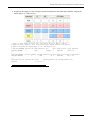
Software Licenses for SS7G31 and SS7G32
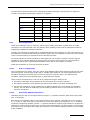
The following SS7G30 licenses can be purchased for SIU mode:
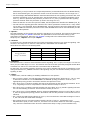
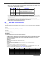
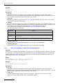
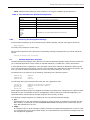
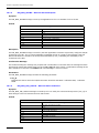
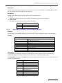
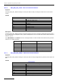
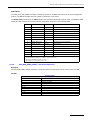
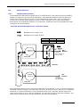
ITEM MARKET NAME
DESCRIPTION
SS7SBG30SIUV
ISUP/BICC supporting 128 CICS, 4 low speed SS7 links, Extended SNMP support
SS7SBG30SIUU
ISUP/BICC supporting 4096 CICS, 16 low speed SS7 links, 16 low speed monitor links, SCCP,
Extended SNMP support
SS7SBG30SIUL
ISUP/BICC supporting 65535 CICS , 64 low speed SS7 links, 2 high speed SS7 links, 64 low
speed monitor links, 2 high speed monitor links,, SCCP, Extended SNMP support
SS7SBG30SIUJ
ISUP/BICC supporting 65535 CICS, 248 low speed SS7 links, 8 high speed SS7 links, 248 low
speed monitor links, 8 high speed monitor links, SCCP, Extended SNMP support
SS7SBG30TCAPL
TCAP supporting 65535 simultaneous active dialogs
SS7SBG30INAPL
INAP supporting 65535 simultaneous active dialogs
SS7SBG30IS41L
IS41 supporting 65535 simultaneous active dialogs
SS7SBG30MAPL
MAP supporting 65535 simultaneous active dialogs
SS7SBG30M3UAS
M3UA supporting 16 SIGTRAN links and up to 154 Kilobytes/sec, equivalent to 16 Low speed
TDM links at 0.6 Erlangs
SS7SBG30M3UAR
M3UA supporting 32 SIGTRAN links and up to 308 Kilobytes/sec, equivalent to 32 Low speed
TDM links at 0.6 Erlangs
SS7SBG30M3UAL
M3UA supporting 64 SIGTRAN links and up to 615 Kilobytes/sec, equivalent to 64 Low speed
TDM links at 0.6 Erlangs
SS7SBG30M3UAK
M3UA supporting 128 SIGTRAN links and up to 1230Kilobytes/sec, equivalent to 128 Low speed
TDM links at 0.6 Erlangs
19
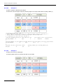
Chapter 2 Specification
ITEM MARKET NAME
DESCRIPTION
SS7SBG30M3UAJ
M3UA supporting 256 SIGTRAN links and up to 2460 Kilobytes/sec equivalent to 256 Low speed
TDM links at 0.6 Erlangs
SS7SBG30M2PAS
M2PA supporting 16 SIGTRAN links and up to 154 Kilobytes/sec equivalent to 16 Low speed TDM
links at 0.6 Erlangs
SS7SBG30M2PAR
M2PA supporting 32 SIGTRAN links and up to 308 Kilobytes/sec equivalent to 32 Low speed TDM
links at 0.6 Erlangs
SS7SBG30M2PAL
M2PA supporting 64 SIGTRAN links and up to 615 Kilobytes/sec equivalent to 64 Low speed TDM
links at 0.6 Erlangs
SS7SBG30M2PAK
M2PA supporting 128 SIGTRAN links and up to 1230 Kilobytes/sec equivalent to 64 Low speed
TDM links at 0.6 Erlangs
SS7SBG30M2PAJ
M2PA supporting 256 SIGTRAN links and up to 2460 Kilobytes/sec equivalent to 256 Low speed
TDM links at 0.6 Erlangs
Note: When using the SS7G32 with SS7MD boards, it is necessary to purchase and install an
appropriate license. A range of licenses are available from Dialogic to permit the user to select
the license that supports the appropriate link capacity for the user's application. The licenses
allow for a specific number of link resources on the SIU that may be shared between SS7MDL4
boards within the system. See the Signaling Servers User Manual Supplement for ATM Operation
for further information regarding licenses associated with the SS7MD board.
2.2.2
Software Licenses for the SS7G21 and SS7G22
The following SS7G20 licenses can be purchased for SIU mode:
ITEM MARKET NAME
20
DESCRIPTION
SS7SBG20ISUP
ISUP/TUP supporting 65535 CICS
SS7SBG20BICC
BICC/ISUP/TUP supporting 65535 CICS
SS7SBG20SCCPCL
Connectionless SCCP
SS7SBG20SCCPCO
Connection-orientated SCCP including Connectionless SCCP support.
SS7SBG20TCAP
TCAP supporting 65535 simultaneous active dialogs
SS7SBG20MAP
MAP supporting 65535 simultaneous active dialogs
SS7SBG20IS41
IS41 supporting 65535 simultaneous active dialogs
SS7SBG20INAP
INAP supporting 65535 simultaneous active dialogs
SS7SBG20M2PA
M2PA supporting up to 200 SIGTRAN links
SS7SBG20M3UAS
M3UA supporting 16 SIGTRAN links and up to 154 Kilobytes/sec equivalent to 16 Low speed
TDM links at 0.6 Erlangs
SS7SBG20M3UAR
M3UA supporting 32 SIGTRAN links and up to 308 Kilobytes/sec equivalent to 32 Low speed
TDM links at 0.6 Erlangs
SS7SBG20M3UAL
M3UA supporting 64 SIGTRAN links and up to 615 Kilobytes/sec equivalent to 64 Low speed
TDM links at 0.6 Erlangs
SS7SBG20SNMP
Extended SNMP support - not required for DK4032 SNMP
Dialogic® DSI Signaling Servers SIU Mode User Manual Issue 10
2.3
Capabilities
This section identifies key capabilities of the Signaling Server. The capabilities of a Signaling Server is
dependent on the number and type of signaling boards installed as defined by the product variant as well as
which software licenses installed.
Use of Signaling Servers in dual pairs increases the capacity of the overall system while still acting as a single
SS7 point code. The numbers given in this section are for a single Signaling Server.
2.3.1
SS7G31 and SS7G32 Signaling Servers Protocol Capabilities
Feature or Protocol
®
SS7G31 Capabilities
SS7G32 Capabilities
Dialogic DSI SS7 Network
Inteface Boards
Up to 1 SPCI4 board or 1 SS7HDP board
Up to 3 SS7DHP boards, up to 3 SPCI4
boards, or up to 2 SS7MD boards
Portable Media Device
USB
USB
PCM per board
4 per SPCI4 or 4 per SS7HDP
4 per SPCI4, 4 per SS7HDP or 4 per
SS7MD
Ethernet interface
4
6
SS7 links per board
4 per SPCI4 or 64 per SS7HDP
4 per SPCI4, 64 per SS7HDP or 124 per
SS7MD
HSL links per board
2 per SS7HDP
2
ATM links per board
M3UA links
4 per SS7MD
256
256
M2PA links
256
256
SS7 linksets
64
64
SS7 links
256
256
SS7 routes
4096
4096
Remote Application servers
256
256
M3UA routes
256
256
Network contexts
4
4
ISUP / BICC
Up to 65,535 CICs, 2048 circuit groups.
Up to 65,535 circuits, 2048 circuit
groups.
SCCP
Up to 512 Local sub-systems, remote subsystems, or remote signaling points.
Up to 512 Local sub-systems, remote
subsystems, or remote signaling points.
TCAP
Up to 65,535 simultaneous active dialogs
Up to 65,535 simultaneous active dialogs
MAP
Up to 65,535 simultaneous active dialogs
Up to 65,535 simultaneous active dialogs
IS41
Up to 65,535 simultaneous active dialogs
Up to 65,535 simultaneous active dialogs
INAP
Up to 65,535 simultaneous active dialogs
Up to 65,535 simultaneous active dialogs
Hosts
Up to 128 hosts
Up to 128 hosts
21
Chapter 2 Specification
22
Dialogic® DSI Signaling Servers SIU Mode User Manual Issue 10
Chapter 3: Architecture
3.1
Introduction
The SIU provides SS7 signaling capability to a telephony application implemented over distributed platforms.
This chapter provides an overview of how the SIU integrates into a system.
3.2
Overview
An intelligent telephony network application can be considered as consisting of physical resources (such as
voice circuits, databases, etc.), an interface to the signaling network and application programs. The SIU
implements a (SS7) signaling interface that is physically independent of the applications that use it.
Resilience may be built into a system by using a pair of SIUs in a dual resilient configuration.
Applications communicate with the SIU using a message-based Inter-Process Communication (IPC)
mechanism implemented transparently over TCP/IP for inter-platform communication. The IPC mechanism
provides a level of operating system independence in the sense that the message definitions are the same
irrespective of the operating system used.
The SS7 configuration parameters are specified in a text file contained within each SIU. This is described in
Chapter 7, “Configuration”.
3.3
Signaling Topologies
A single SIU may be used standalone, or two units may be configured in a dual resilient configuration. Each
SIU may support one or more application (host) computers.
The host computer contains the physical resources controlled by the signaling, such as voice circuits and
databases. The SIU extracts SS7 information and conveys it to the application software, which can control
the resource accordingly and issue the required responses to the SIU for transport over the SS7 network. In
telephony applications, the voice circuits may be distributed between more than one application (or host)
computer for resilience.
The minimal system consists of a single SIU connected to a single host via Ethernet as illustrated in Figure 3.
Dashed lines indicate optional equipment.
Figure 3. Signaling Paths in a Single SIU Configuration
Host Computer
(Application 1)
TCP/IP
Network
SIU A
Host Computer
(Application 2)
SS7
Network
Host Computer
(Application n)
This system may be scaled up at initial system build time or later to a dual resilient configuration connected
to the maximum number of hosts supported. See Figure 4.
23
Chapter 3 Architecture
Figure 4. Signaling Paths in a Dual Resilient Configuration
SIU Pair
Host computer
(Application 1)
SIU A
SS7
Network
Host computer
(Application 2)
SIU B
Host computer
(Application n)
TCP/IP
Network
The SIU may connect to a number of adjacent signaling points, the maximum number being limited only by
the maximum number of link sets supported by the unit. The adjacent SS7 nodes may be Signaling Transfer
Points (STPs), Signaling Switching Points (SSPs) or Signaling Control Points (SCPs). The following diagrams
indicate possible configurations, although these are not exhaustive.
Figure 5 shows a single SIU connected to an adjacent SSP/SCP and/or STP.
Figure 5. Single SIU Connected to SSP/SCP or STP
SSP/
SCP
F-links
’
F-links
SSP/
SCP
SIU A
A-links
STP
In a dual resilient configuration, the SIU pair share the same SS7 point code. Figure 6 shows an SIU pair
connected to a single adjacent SSP/SCP.
Figure 6. SIU Dual Configuration with Connections to SSP/SCP
SIU A
Inter-SIU
Linkset
F-links
SSP/SCP
SIU B
F-links
The SIU pair may also be connected to a single adjacent STP (or combination of SSP and STP) as shown in
Figure 7.
24
Dialogic® DSI Signaling Servers SIU Mode User Manual Issue 10
Figure 7. SIU Dual Configuration with Connections to STP
SIU A
Inter-SIU
Linkset
A-links
STP
SIU B
A-links
Finally, Figure 8 shows an SIU pair connected to a “mated” STP pair. In this configuration, all the links from
the first STP must be terminated at SIUA and all the links from the second STP must be terminated at SIUB.
Figure 8. SIU Dual Configuration with Connections to Mated STP Pair
A-Links
STP
SIU A
Inter-SIU
Linkset
C-Links
SIU B
A-Links
3.4
STP
Multiple Network Support
The SS7 Network Context together with a signaling point code uniquely identifies an SS7 node by indicating
the specific SS7 network it belongs to. The Network Context may be a unique identifier for a physical SS7
network, for example, to identify an ANSI, ITU, International or National network, or it may be used to
subdivide a physical SS7 network into logical sub-networks. An example of the use of logical networks is in
provisioning, where the user requires 64 SS7 links between two point codes in a network. As the SIU
supports 16 links in a link set, and one link set between two points in a network, only 16 links between two
points would normally be achievable. However, if the network is divided into four logical Network Contexts,
then up to four link sets may be created between the two point codes, one in each Network Context, thus
allowing up to 64 SS7 links to be configured between the two points.
Note: The Network Context has significance only to the configuration of the local node (including the
hosts). No external messages include any indication of the Network Context and the
configuration of remote systems is unaffected.
The SIU mode is able to support architectures in which a single SIU or dual resilient SIU pair are connected
into one or more different SS7 networks. The SIU or SIU pair can also independently terminate multiple local
point codes within the same network. Section 3.4.1 and Section 3.4.2 following describe these different
architectures. Further details on the specific changes required to convert a configuration to use multiple
Network Contexts can be found in Section 8.3, “Configuring Multiple Network Contexts” on page 194.
The SIU can support up to four Network Contexts where each Network Context is a different network or
different independent local point code within the same network. In the configuration commands or MMI
commands, Network Contexts are designated NC0, NC1, NC2 or NC3. Network Context NC0 is also referred
to as the default Network Context since this is the Network Context that is assumed if no other explicit value
is specified within the command.
25
Chapter 3 Architecture
3.4.1
Support for Multiple Local Point Codes
In some situations, it is desirable to have an SIU terminate more than one local point code within the same
SS7 network. Each local point code can have separate routes and associated pairs of link sets to a
destination point code. This means that adding additional local point codes allows additional link sets to be
used to send traffic to a destination point code. As link sets are limited to 16 links adding more link sets
using multiple local point codes effectively allows a larger total number of links to carry traffic to any single
destination point code.
Figure 9 shows a simple configuration that uses two Network Contexts to allow a single SIU to connect to the
remote node using two link sets from two independent local point codes. Link set 0 and 1 are configured in
Network Contexts NC0 and NC1 respectively.
Figure 9. Multiple Network Contexts to Support Multiple Local Point Codes
NC0
Point Code 1
Link
Set
0
Remote Node
Point Code 3
SIU
Link
NC1
Point Code 2
Set
1
Figure 10 extends the previous example to show a configuration with an STP pair. This configuration uses
two Network Contexts to allow a single SIU to connect to the Remote Node using four link sets from two
independent local point codes. An equivalent configuration using a dual resilient pair is also possible.
Figure 10. Multiple Network Contexts with an STP Pair
NC0
Point Code 1
Link Set 0
STP A
Point
Code 4
Lin
kS
et
1
SIU
k
Lin
NC1
Point Code 2
26
Remote Node
Point Code 3
t2
Se
Link Set 3
STP B
Point
Code 5
Dialogic® DSI Signaling Servers SIU Mode User Manual Issue 10
3.4.2
Support for Multiple Networks
The Network Context-based configuration of the SIU mode allows the settings and behavior to be configured
independently for each Network Context. This allows a system to be configured with mixed ITU and ANSI
network types or allows multiple networks of the same type to be configured with different settings.
Figure 11. Multiple Network Contexts Support for Multiple Network Types
NC0
Point Code 5
NC1
Point Code 6
Link Set 0
Link Set 1
ITU Network
Remote Node
Point Code 1
14-Bit PC
ITU Network
Remote Node
Point Code 2
16-Bit PC
SIU
NC2
Point Code 7
NC3
Point Code 8
Link Set 2
Link Set 3
ITU Network
Remote Node
Point Code 3
24-Bit PC
ITU Network
Remote Node
Point Code 4
24-Bit PC
27
Chapter 3 Architecture
3.4.3
Protocol Handling for Multiple Network Contexts
Figure 12 shows the use of multiple Network Contexts from an application perspective and provides
examples of the module IDs for the various application layers.
Figure 12. Module IDs for Use with Multiple Network Contexts
MAP
0x15
ISUP
0x23
3.4.3.1
IS41
0x25
INAP
0x35
TCAP
0x14
DTS
0x30
SCCP NC0
0x33
SCCP NC1
0x36
SCCP NC2
0x37
SCCP NC3
0x38
MTP NC0
0x22
MTP NC1
0x82
MTP NC2
0x92
MTP NC3
0xb2
MTP Applications
Since there is one instance of MTP3 for each Network Context, messages that are destined for a specific
network must be sent to the correct MTP module ID as shown in Figure 12 above.
In most SIU configurations, MTP is not the highest protocol layer and the sending of messages to the correct
module is handled by the higher layer modules without further user interaction.
3.4.3.2
SCCP Applications
In the same manner as MTP3, there is one instance of SCCP for each Network Context; therefore, messages
that are destined for a specific network must be sent to the correct SCCP module ID as shown in Figure 12.
When TCAP or DTS is used above SCCP, those modules handle the sending of messages to the correct
module without further user interaction.
3.4.3.3
ISUP Applications
ISUP applications do not need modification, the config.txt parameters are sufficient to identify the Network
Context.
28
Dialogic® DSI Signaling Servers SIU Mode User Manual Issue 10
3.4.3.4
TCAP, MAP, INAP and IS41 Applications
Where a dialog is initiated remotely, no change is required since TCAP, MAP, INAP and IS41 automatically
determine which Network Context is appropriate. Where the dialog is initiated locally, the application must
specify the Network Context to which the message is destined. This effectively indicates the point code to be
used as the originating point code.
The Network Context should be indicated in the first message for the dialog being used. In the case of TCAP,
this is in the first TCAP service request, typically an Invoke Req, using the TCPPN_NC parameter. For MAP,
IS41 and INAP, the Network Context should be indicated in the Open Request message, instead of using the
MAPPN_NC, IS41PN_NC and INAPPN_NC parameters respectively.
If a Network Context is not specified, the default Network Context, NC0 is assumed.
3.4.3.5
DTS Applications
DTS users should follow the instruction in Section 3.4.3.4 above, which also apply when using DTS. The
DTS_ROUTING_REQ message includes a DTSPN_network_context parameter that should be used to
indicate the network and hence the local point code that a specified sub-system is part of. If this parameter
is not specified, the default Network Context, NC0 is assumed.
To route messages to the correct SCCP instance, you must specify the DTC option,
DTC_ROUTE_MSG_VIA_DTS. This option is set via bit 0 in the options field of the DTC_MSG_CONFIG
(0x776c) configuration message.
3.5
Connection of Bearer Channels
For some applications, the signaling channels are multiplexed onto the same physical bearer as the voice
circuits being controlled by the application. In these circumstances, the signaling channels may be extracted
by external cross connect equipment and connected to the SIU, or the SIU may extract the signaling and
route the voice circuits to the resources on the application. These two approaches are shown in the diagrams
below.
Figure 13 shows the first case where the signaling is provided separately from data circuits.
Figure 13. Signaling Separate from Data Circuits
SIU A
Signaling
Channels
Ethernet
Host 1
PCM 1
Host N
PCM N
Figure 14 shows the second case where the signaling channel is extracted by the SIU.
29
Chapter 3 Architecture
Figure 14. Signaling Channel Extracted by SIU
Signaling
Channel
Ethernet
SIU A
Host 1
PCM1
Signaling
Channel
Host 2
PCM2
Host 3
PCM3
Host 4
PCM4
In Figure 13 and Figure 14 above, the label PCM represents a multiplexed PCM bearer (T1/E1) consisting of a
number of data circuits. For both cases, these circuits are terminated on the host computers.
In the first case (Figure 13), the common channel signaling is received on a different physical bearer to the
data channels. The voice circuits do not pass through the SIU but are connected directly to the voiceprocessing platform.
In the second case (Figure 14), the common channel signaling is extracted from the first two PCM trunks,
and the voice channels are transported through the SIU to host 1 and host 2. The remaining PCM trunks,
which do not contain any signaling, are connected directly to host 3 and host 4.
In both cases, each host receives the signaling information for the channels that it manages over the TCP/IP
network.
The connection of voice circuits through the SIU is controlled by data stored in the SIU.
30
Dialogic® DSI Signaling Servers SIU Mode User Manual Issue 10
3.6
Software Environment
The SIU software environment is based on a number of communicating processes, each with its own unique
identifier or “module ID”. Each module in the system runs as a separate task, process or program (depending
on the type of operating system). Inter Process Communication (IPC) is message based and is achieved by
using the set of library functions in Table 1.
Table 1. Library Functions for Inter Process Communications
Function Name
Purpose
getm( )
Allocate an IPC message
relm( )
Release an IPC message
GCT_send( )
Send an IPC message to a process
GCT_receive( )
Blocking receive
GCT_grab( )
Non-blocking receive
GCT_set_instance( )
Indicate that a message is destined for a particular SIU
GCT_get_instance( )
Determine which SIU sent a message
These functions are provided as a library to allow the application programs running on the host computer to
communicate with the SIU. The IPC message (or MSG) is a “C” structure containing a fixed format header
field and a data buffer for variable length parameter data. A complete description of the IPC functions and
message structure is given in the Software Environment Programmer’s Manual.
In a dual resilient configuration, SIUA is identified by the IPC mechanism as instance 0 and SIUB as
instance 1.
3.7
Communication Between SIU and Host Application
Host software, in binary form, enabling user applications on Windows®, Linux, and Solaris to communication
with the SIU is available from your Dialogic support channel.
This software allows the environment described above to be established on the host operating system. This
software consists of the IPC library functions and a number of processes that manage the communication
between the host and each SIU.
The SIU identifies each unique host computer using a host identifier value (or host_id). Values range from
zero to one less than the total number of hosts. The first host is assigned host_id 0.
A process running on the host computer manages the communication between the application and an SIU.
The application issues two messages to this process to connect to (and use) an SIU. Each host connects to a
different TCP/IP port on the SIU; hence the port selected assigns the host_id value to the computer
requesting the connection. The host receives status indications (in the form of an IPC message) from each
connected SIU indicating changes in the availability of this link. If a failure occurs, an event is sent to the
host indicating that the connection to the SIU has been lost, allowing the host to take corrective action.
Once the SIU detects an active connection to a host computer, all configured SS7 links are activated. If all
host connections fail, the signaling links are deactivated (until one or more host links become active).
3.8
Inter-SIU Communication
In a dual resilient configuration (one unit nominated as SIUA, the other as SIUB), two physically independent
communication channels exist between the two units.
Control information is exchanged over the Ethernet. Signaling messages are exchanged (when necessary)
over an inter-SIU SS7 link set, which must be configured for correct dual resilient operation.
The preferred route for messages transmitted from an SIU is over the links connecting that unit to the
appropriate adjacent point code (a point code that is either the final destination or a route to the final
destination). If no signaling link to an appropriate adjacent point code is available, the transmit traffic is
passed to the other SIU via the inter-SIU link set. If the inter-SIU link set fails, transmit messages fall back
to being passed over the Ethernet.
31
Chapter 3 Architecture
If the inter-SIU link set fails (causing the Ethernet link to be used for transmitted messages), message loss
may occur at the point where the preferred route fails.
The SS7 network is free to deliver received messages to either SIU. Special processing at the User Part level
(ISUP or TCAP) ensures that any message received for a call or transaction being handled by the other unit is
routed over the Ethernet.
The inter-SIU link set is configured in the same manner as normal link sets, for details, refer to Chapter 7,
“Configuration”.
The inter-SIU link set may consist of one or more signaling links configured on one or more signaling ports
(T1/E1), distributed between one or more signaling boards. Resilience on the Inter SIU link set may be
achieved by configuring two links in the inter-SIU link set, each on a separate signaling board. The inter-SIU
link may also be conveyed over M2PA or M3UA avoiding the requirement for a TDM link and cabling between
the units.
3.9
Call Control Applications
3.9.1
Standalone Operation
When the SIU is not used in a dual resilient configuration, the circuits that are used by the application are
activated on the SIU automatically at start-up. You are free to use these circuits for telephony once the
connection between the host and SIU is active (and the SS7 links are in service).
3.9.2
Call Control Interface
Call control primitives are conveyed between ISUP running on the SIU and the host using IPC messages. One
message type is used to send request messages from the user to the User Part module, while a second
message type is used to send indications in the opposite direction. A third message type provides the user
application with indications of the remote signaling point status.
The message types are:
•
ISP_MSG_TX_REQ
Conveys primitive from host to User Part.
•
ISP_MSG_RX_IND
Conveys primitive from User Part to host.
•
ISP_MSG_STATUS
Conveys remote signaling point status to the host.
The format of these messages is defined in the ISUP Programmer’s Manual.
In a dual resilient configuration, it is necessary for the application to assign a group to a particular SIU before
any call control or management primitives can be exchanged for circuits in that group. The host ensures that
circuit-related messages are routed to the correct SIU by setting the destination instance of the IPC message
using the GCT_set_instance( ) library function. Messages issued by the SIU to a host computer are
automatically delivered to the host_id that is specified as part of the per circuit group data in the SIU
configuration.
An example telephony application is provided in “C” source code. This makes use of a library of interface
functions that provide you with a “C” structured representation of the protocol primitives for convenience.
32
Dialogic® DSI Signaling Servers SIU Mode User Manual Issue 10
3.9.3
Circuit Supervision Interface
The Circuit Supervision Interface allows the host to carry out the following operations:
•
•
•
•
•
Reset a circuit or circuit group
Abort a reset cycle
Block a circuit or circuit group (Maintenance, Hardware, or Software)
Unblock a circuit or circuit group (Maintenance, Hardware, or Software)
Abort a blocking or unblocking attempt
Commands originated by the host take the form of a Circuit Group Supervision Request. On completion of
command execution, the host receives notification in the form of a Circuit Group Supervision Confirmation,
indicating that the expected response or acknowledgement has been received from the network for the
command. Events initiated at the remote end of the network are notified to the user in a Circuit Group
Supervision Indication.
The message structure and parameters for each message are defined in relevant protocol Programmer’s
Manual.
3.9.4
ISUP Detection of Failed SIU Hosts
It is possible to configure ISUP to detect failed (or inactive) SIU hosts and initiate circuit group blocking to
the network. This ensures that the network does not attempt to initiate calls on circuits for which there is no
active application and calls would consequently fail.
The use of this feature requires the user application to respond to the CAL_MSG_HEARTBEAT message (see
Section 10.1.11, “CAL_MSG_HEARTBEAT” on page 238) that is periodically issued by the ISUP module. In
the event that no response is received within a pre-determined time, the ISUP module initiates hardware
circuit group blocking to the network.
The feature is optional and is activated by setting bit 9 in the <options2> parameter of the
ISUP_CFG_CCTGRP command. When the bit is set, heartbeat messages are generated and sent to the user_id
configured for the circuit group. If the option is not set, automatic blocking of circuits is not performed for
the circuit group and heartbeat messages are not sent to the user application.
When the feature is activated, the ISUP module periodically sends a heartbeat message,
CAL_MSG_HEARTBEAT, to the user application, to determine status. A single heartbeat message is sent
every 30 seconds regardless of the number of circuit groups configured per SIU host. The application must
respond by confirming the message (using the confirm_msg( ) function instead of releasing the message
using the relm( ) function).
If the user application fails to respond to a heartbeat message within 3 seconds, the ISUP module considers
the application to be unavailable and out of service. Circuit groups associated with the application and for
which autoblocking is configured are hardware blocked and a blocking message is sent to the network (CGB).
Once circuit groups have been blocked, ISUP continues to send heartbeat messages with the
UIHB_FLAGS_CGRPS_BLOCKED flag (bit 0) set to a value of 1.
Following recovery, the application should clear the automatically imposed hardware blocking condition by
requesting either a reset or hardware unblocking using the normal circuit supervision request mechanism
and resuming to subsequent heartbeat messages.
33
Chapter 3 Architecture
3.10
Transaction-Based Applications
Applications that need to exchange non-circuit related information over the SS7 network (such as for the
control of a Mobile Telephone Network or for an Intelligent Network application) do so by exchanging
information between sub-systems using the services of SCCP. A sub-system is an entity that exchanges data
with other entities by using SCCP.
Note: TCAP and the higher layer protocol modules INAP, MAP, and IS41 may be supported on the SIU
directly or may be distributed onto the host using the Distributed Transaction Server (DTS)
functionality, allowing a highly scalable architecture. A DTS may also be used when MAP, INAP or
IS41 operate on the SIU and the user wishes to distribute its applications across multiple hosts.
For an overview of DTS operation, see the Dialogic® SS7 Protocols DTS User Manual.
The SIU provides the capability to configure local sub-systems and routing to remote resources. The
intelligent functionality of each local sub-system is provided by the user application running on one or more
host computers.
3.10.1
Management of Local SCCP Sub-Systems
The availability of local sub-systems is conveyed by sending SCCP management request messages of type
SCP_MSG_SCMG_REQ as defined in the SCCP Programmer’s Manual to the TCAP module on the SIU. These
messages can be issued either by the individual local sub-system tasks (that is, APPn_TASK_ID) or by the
management module (that is, REM_API_ID) on behalf of all the local sub-systems. This choice is left to
you.
You may request the return of a confirmation message (using the rsp_req field) from the SIU to verify that
the message has been received. Successful receipt of a confirmation message implies that the path through
the protocol stack down to and including the SCCP module is operational.
Note: The confirmation message is returned to the module that issued the original management
request. This is not necessarily the local sub-system module.
3.10.2
Sub-System In Service
When the local sub-system task first starts running a User In Service (UIS) request should be issued to the
SIU.
While the local sub-system remains operational, further UIS requests should be issued to the SIU on a
periodic basis. It is recommended that a UIS request be issued approximately every 12 seconds.
On receipt of each UIS request, the SIU starts (or restarts) a 30-second timer. Should the timer expire
before the next UIS request is received, then the SIU assumes that the local sub-system is no longer
operational and reacts as if a User Out of Service (UOS) request had been received for the local sub-system.
3.10.3
Sub-System Out of Service
When the local sub-system task is to be taken out-of-service in a controlled manner a User Out of Service
(UOS) request should be issued to the SIU.
As there is no requirement for the UOS request to be issued by the local sub-system to which it refers,
another module may issue the UOS notification if a local sub-system goes out of service in an uncontrolled
manner.
34
Dialogic® DSI Signaling Servers SIU Mode User Manual Issue 10
3.10.4
TCAP-Based Applications
For TCAP operations, each TCAP user (or sub-system) is implemented as a unique process running on one or
more host computers. The module identifier for each local sub-system is assigned in the SIU configuration
file.
Each dialog (or conversation) is uniquely identified by a dialog ID (identifier). Definitions in the SIU protocol
parameter file reserve a separate contiguous block for incoming and outgoing dialogs. Each SIU can manage
up to 65,535 simultaneous active dialogs.
In a dual resilient configuration, the maximum supported number of dialogs is available on each unit. A
remotely-initiated dialog is handled by the SIU that received the first TCAP message from the remote TCAP
entity. An outgoing dialog is handled by the SIU that processes the first dialog or component request from
the user application. Each dialog is permanently associated with either SIUA or SIUB for its duration. The
application should use the GCT_set_instance( ) to address each TCAP primitive request to the correct SIU.
The GCT_get_instance( ) function enables the originating SIU for each primitive indication to be identified.
Note: Systems using TCAP should ensure that the rsi routing algorithm is set to “-l1” to enable the full
number of TCAP dialogs to be available to the host application and to cause the TCAP primitives
to be routed according to the SIU instance.
3.10.5
TCAP Application Interface
The interface between the user application and the TCAP protocol is defined in the TCAP Programmer’s
Manual and the SCCP Programmer’s Manual.
An example application is provided in “C” source code to demonstrate how a local sub-system application
program can interface with the TCAP/SCCP protocols running on the SIU. This makes use of a library that
provides the user with a “C” structured representation of the protocol primitives for convenience.
Each local sub-system task should notify the SIU as it becomes available using a User In Service N-STATE
Request (UIS) and before it terminates using a User Out of Service N-STATE Request (UOS). If the local
heartbeat detection mechanism is enabled, the local sub-system should also continue to issue UIS N-STATE
Requests approximately every 12 seconds.
Maintenance events and software events from TCAP and SCCP are reported to the user’s own management
module, which uses the REM_API_ID module ID. This module receives the following messages:
•
TCP_MSG_MAINT_IND
Maintenance event from TCAP.
•
TCP_MSG_ERROR_IND
Software event from TCAP.
•
SCP_MSG_MAINT_IND
Maintenance event from SCCP.
•
SCP_MSG_ERROR_IND
Software event from SCCP.
The user’s management module is typically configured to receive SCCP management indications by
configuring it as a concerned local sub-system.
Note: While the user’s management module is not a local sub-system in terms of sending and receiving
protocol primitives, it is configured as a local sub-system on the SIU to allow it to receive SCCP
management indications.
SCCP management indications use the following message:
•
SCP_MSG_SCMG_IND
Management indication from SCCP.
35
Chapter 3 Architecture
The user’s management task may use the following message to set up default parameters within the TCAP
module, although you may elect to insert default parameters prior to calling the TCAP library functions:
•
TCP_MSG_DEF_PARAM
Set up default parameter values.
None of the other messages described in the TCAP Programmer’s Manual should be issued by the application
because they would conflict with the internal operation of the SIU. In particular, the TCAP configuration
message is issued by the internal SIU management task at initialization.
The only messages that may be sent directly to the SCCP module are the messages to read status and
statistics and to add and remove entries in the Global Title Translation table. These are message types
SCP_MSG_R_STATS, SCP_MSG_R_SSR_STATS, SCP_MSG_GTT_ADD and SCP_MSG_GTT_REM as described
in the SCCP Programmer’s Manual.
3.10.6
Multiple TCAP Application Hosts
Redundancy may be achieved in the application space by distributing the local sub-system application
between more than one application platform (or host) connected to the SIU via the Ethernet. The parameter
file on the SIU assigns ranges of dialog identifiers for incoming and outgoing dialogs for each host. The
application program running on each host must therefore ensure that only dialog identifiers from the
assigned range are used.
Incoming dialogs are distributed between multiple instances of the application using an algorithm defined in
the SIU config.txt file. This may be set to load balance between hosts, cycle through each host in turn or fill
the hosts in sequence.
3.10.7
MAP Application Interface
The Mobile Application Part (MAP) layer of the SS7 protocol enables the control of services within the GSM
mobile telephone network.
The interface between the user application and the MAP protocol is defined in the MAP Programmer’s Manual.
An application interfacing to the MAP protocol requires the sub-system management procedures described
above for SCCP and TCAP.
Distribution of the application above MAP between multiple hosts MAP can be achieved by running DTS above
MAP on the SIU. See the DTS User Guide for further information.
3.10.8
IS41 Application Interface
The IS41 layer of the SS7 protocol enables the control of services within the ANSI mobile network.
The interface between the user application and the IS41 protocol is defined in the IS41 Programmer’s
Manual. An application interfacing to the IS41 protocol requires the sub-system management procedures
described above for SCCP and TCAP.
Distribution of the application above IS41 between multiple hosts can be achieved by running DTS above
IS41 on the SIU. See the DTS User Guide for further information.
3.10.9
INAP Application Interface
The Intelligent Network Application Part (INAP) layer of the SS7 protocol enables the control of services
within the intelligent network.
The interface between the user application and the INAP protocol is defined in the INAP Programmer’s
Manual. An application interfacing to the INAP protocol requires the sub-system management procedures
described above for SCCP and TCAP.
Distribution of the application above INAP between multiple hosts can be achieved by running DTS above
INAP on the SIU. See the DTS User Guide for further information.
36
Dialogic® DSI Signaling Servers SIU Mode User Manual Issue 10
3.11
Resilience
3.11.1
IP Resilience
The SIU has up to six IP ports. These ports may be configured with IP addresses in separate IP networks to
allow greater IP resilience on the SIU. IP addresses are configured using the IPEPS command. The IPGWI
command allows configuration of the default gateway and additional gateways.
As the SIU supports static, rather than dynamic IP routing, the SIU may not be configured with different IP
addresses within the same IP network. Instead, resilience between two IP ports within the same network can
be achieved by using IP port bonding, which allows two physical IP ports to be bonded together in an active/
standby configuration under a single IP address. See Section 8.2, “IP Port Bonding” on page 193 for more
information.
3.11.2
Dual Resilient Operation
In a dual resilient configuration, optimal performance is achieved by distributing control of the circuit groups
evenly between SIUA and SIUB. The application requests a particular SIU to manage the signaling for each
circuit group at run-time. Control of a circuit group may be transferred by the host from one SIU to the other
at any time.
Both SIUA and SIUB contain the same circuit group data in the configuration file. The application activates a
group by sending an Activate Group User Command to a particular SIU. The circuits in this group may then
be used by the application for telephony. The application may deactivate the group by sending a Deactivate
Group User Command to the controlling SIU. This group may then be activated on the other SIU if required.
The format of the User Command is described in Chapter 10, “Application Programming Interface”.
The application ensures that call primitives and activate/deactivate group commands are routed to the
correct SIU by setting the destination instance of the IPC message that conveys the primitive. SIUA is
instance 0 and SIUB is instance 1. The GCT_set_instance( ) library function is provided for this purpose.
Unit failure is indicated to the host by receipt of a status message indicating that the connection to an SIU
has been lost. If this occurs, the circuit groups managed by the failed unit may be activated on the available
unit. This transfer does not affect calls in the speech/connected state. Calls that are currently being set-up
fail; these calls should be attempted again once the transfer is complete.
The transferred circuits should be reset by the application once any call that was active during the transfer
has completed. Idle circuits may be reset immediately following the transfer.
3.11.3
Fault Tolerance in Call Control Applications
See Appendix A, “SIU Resilience” for information on building fault tolerant SS7 systems for call control
applications using Signaling Gateways SIUs.
3.11.4
Fault Tolerance in Transaction Processing Applications
See Appendix A, “SIU Resilience” for information on building fault tolerant SS7 systems for transaction
processing applications using Signaling Gateways SIUs.
3.11.5
Use of Multiple Host Computers
For telephony, the circuits multiplexed on a single T1/E1 PCM trunk are usually controlled by the same host.
The control of a number of T1/E1 trunks may be divided between more than one host.
The circuits available to the SS7 telephony User Part (ISUP) on the SIU are configured in groups. The
configuration data for each group may include an optional host_id, specifying which host computer controls
the physical resources. This ensures that protocol messages received for each circuit are routed to the
correct host computer.
37
Chapter 3 Architecture
3.11.6
Backup Host Capability
The ability to configure backup hosts allows management and/or signaling messages to be redirected to a
backup host application in the event of primary host failure. Backup hosts can be employed when configured
for ISUP. Backup hosts may also be used for SCCP operation; however, they may not be used in
configurations that utilize DTS/DTC.
When using ISUP for example, this mechanism allows continued use of circuits if the primary host for a
circuit group were to fail. Once the primary host link has been recovered, messages are again sent to it from
the SIU. See the SIU_HOSTS command, Section 7.4.1.
3.12
Management Reporting
The SIU reports management alarms such as PCM trunk status and SS7 level 2 link status to a single
software process, identified as module_id 0xef, that exists by default on host 0. The user management
application is responsible for interpreting the management messages (described in Chapter 10, “Application
Programming Interface”), performing the appropriate action and distributing these messages to other hosts
if required. The identity of the default management host is displayed by the DMHOST parameter on the
CNSYP MMI command and may be changed through use of the CNSYS command.
Any host may assume the role of management by sending a management request (in the form of an
API_MSG_COMMAND request). On receipt of this request, the SIU begins to send management events to the
new host. Unlike the setting of the DMHOST through MMI setting of a management host, using the
API_MSG_COMMAND will require the user to transmit the API_MSG_COMMAND with the desired
management host identify each time the SIU is restarted.
An optional second management host may also be activated by sending a management request. On receipt
of this request, the SIU sends management events to both management hosts.
The selection of which host is the manager, as well as the configuration of an additional management host,
allows a user to build a resilient solution to meet their management event reporting needs.
The SIU also maintains a log of management messages for diagnostic purposes in the "syslog" subdirectory
of the siuftp account. This log is maintained as a rolling log of up to 10 5MB files containing management
messages transmitted to the management host as well as some further diagnostic data. The most recent
maintenance log file will have the name “maint.log” the next most recent “maint.log.1” and then
“maint.log.2” and so on.
3.13
Alarms
The Dialogic® DSI Signaling Server products are able to detect a number of events or alarm conditions
relating to either the hardware or the operation of the protocols. Each alarm condition is assigned a severity/
class (3=Critical, 4=Major, 5=Minor) and a category and ID, which give more detail about the alarm. There
are a number of mechanisms described below, by which these conditions can be communicated to
management systems, and ultimately to the system operator. See Section 5.4, “Alarm Listing” on page 50 to
for a list of alarm types, and their reporting parameters.
38
•
Active alarms are indicated on the front panel of the Signaling Server (except SS7G31), with three LEDs
identifying severity; CRT, MJR, MNR.
•
Active alarms may be indicated remotely from the Signaling Server (except SS7G31), when the alarm
relay outputs are connected to a remote management system.
•
Alarm events (occurrence and clearing, class, category and ID) may be reported via Management
messages to the host application as detailed in Chapter 10, “API Commands”, thus permitting remote
monitoring and/or logging.
•
Alarm events may be reported to an SNMP manager. SNMP support is described in Section 5.3, “SNMP”
on page 46.
•
A system operator can obtain a listing of the current alarm status (CLA, CATEGORY, ID and TITLE) using
the ALLIP management terminal command described in Section 6.8.1, “ALLIP” on page 64. Test Critical,
Major, or Minor may be activated using the ALTEI management command and cleared using the ALTEE
management command.
Dialogic® DSI Signaling Servers SIU Mode User Manual Issue 10
Chapter 4: Licensing, Installation and Initial Configuration
4.1
Software Licensing
Functional capabilities and signaling protocols are activated on the Signaling Server through the use of
software licenses. The following section provides information on the purchase of software licenses as well as
information relating to temporary operation of the Signaling Server without software licenses.
Software licenses supported on the Signaling Server for SIU mode are identified in Section 2.2, “Software
Licenses” on page 19.
4.1.1
Purchasing Software Licenses
1. Place an order using your normal sales channel, quoting the product ID for the software option required.
At this point in the process, there is no need to know details of the specific Signaling Server on which the
option is to be installed (the target Signaling Server).
The order ships through the normal supply channels and you will receive a paper License Certificate. The
certificate contains the license terms for using the Signaling Server software option and a unique License
ID that is needed to activate the license.
2. When the License Certificate is received, you should first read the full terms of the software license:
— If you do not agree with the software license terms, contact your sales channel for a refund. You
must not activate the software license.
— If you agree the software license terms, you can continue with Step 3..
3. The next stage is to identify the Dialogic® DSI Signaling Server product(s) on which the software option
is to be activated. To do this, you need to obtain the UNIT ID for the Signaling Server which is done by
executing the CNSYP MML command (see Section 6.9.28 on page 82) on the target Signaling Server.
4. Once you have the License ID and the UNIT ID, the license can be activated on the Signaling Server.
License Activation is the process of submitting the License ID and UNIT ID so that a License File can be
generated and sent for installation on the target Signaling Server.
The License Activation process is web-based, and the License File is sent by email. To activate the license
perform the following steps:
a. Visit the web site: http://membersresource.dialogic.com/ss7/license/license.asp (or an alternative URL
if listed on the License Certificate).
b. Provide the following information:
— Name
— Company
— Country
— Email address (this will be used to send the License File)
c. Provide the following information about the Signaling Server:
— Operating System - Enter "Signaling Server".
— Host ID - Enter the UNIT ID.
— User machine identification - A string, typically the SIU name, used by you to identify the unit. This
may be any value relevant to you, for example, "SIU_TEST_UNIT1".
d. Provide the License ID (taken from the License Certificates) for each protocol that is to be licensed on
the target Signaling Server.
e. Submit the form. You will receive confirmation that your request has been submitted. Subsequently, you
will receive your License File by email.
39
Chapter 4 Licensing, Installation and Initial Configuration
4.1.2
Temporary Licenses
A temporary software license can be issued for a spare or backup signaling server in the event that an
existing server encounters a problem that requires the unit to be repaired or replaced. Alternatively, a new
permanent license, based on the licenses from the failed unit, can be issued for a spare signaling server.
The process for obtaining a temporary license file is almost identical to that of activating a new license. On
the web based activation form, the License IDs should be prefixed with the following 4 characters: BAK-. For
example, if the license ID on the certificate is G20-ISUP-785-9187, the license ID specified on the web form
for the corresponding temporary license would be BAK-G20-ISUP-785-9187. The Host ID entered on the
form is that of the replacement system on which the license will be installed. A temporary license file will
then be sent to the email address you specify during the license activation.
A temporary license will allow operation of a spare/backup unit for a period of 30 days from date of issue,
after which the system software cannot be restarted. It is therefore important to seek authorization to reactivate the original license(s), to perform the new activation, and to install the new license file prior to the
expiry of the 30 day period.
4.1.3
Trial Licenses
When the trial license is active, SIU protocols are available on the unit for 10 hours. After this period, the
system will automatically re-boot and return to normal operation supporting only the capabilities that are
licensed on the system. To activate trial mode, the unit should be restarted as follows:
MNRSI:RESTART=TRIAL;
A new “Trial mode” alarm, will be active whenever the system is operating in this mode.
4.2
Installing the Signaling Interface Unit
Caution: The SIU should only be installed by suitably qualified service personnel. Important safety and
technical details required for installation are given in the appropriate system hardware manual.
In order to complete the installation of the SIU unit, proceed as follows:
1. Connect a VT100 terminal to the unit (see Section 4.2.1).
2. Set the IP addresses of the unit (see Section 4.2.2).
3. Check whether a software download and upgrade is required (see Section 4.2.3).
4. Install any additional protocol software option licenses that you may have purchased. (see
Section 4.2.4).
5. Check that the system is operating in SIU mode. This is achieved by connecting a VT100 terminal and
issuing the CNSYP command. The resulting output shows the operating mode, which is either “SIU” or
“SGW” (see Section 6.9.28, “CNSYP” on page 82).
If the operating mode is not “SIU” and needs to be reset to “SIU” mode, this can be achieved by
restarting the software with the following MNRSI command:
MNRSI:SYSTYPE=SIU,RESTART=SOFT;
6. Apply the configuration to the unit (see Section 4.2.5, “Configuration Procedure” on page 43). See also
Chapter 8, “Configuration Guidelines” for some example configurations.
7. The SIU is designed to work in a complete system with one or more host platforms. Typical system
topologies are shown in Section 3.3, “Signaling Topologies” on page 23. These should be set up as
described in Chapter 9, “Host Software”.
40
Dialogic® DSI Signaling Servers SIU Mode User Manual Issue 10
4.2.1
Connecting a VT100 Terminal
A VT100 compatible terminal can be connected, using a DKL29 cable, to the serial port (COM2) on the rear of
the unit. After pressing the carriage return (Enter) key, the Signaling Gateway interface prompt is displayed.
Default serial port settings are 9600 baud, 8 data bits, 1 stop bits and no parity bits.
The output on the VT100 screen is similar to one of the following:
SS7G30(SIU) logged on at 2004-01-20 14:52:29
<
to indicate SIU operation,
OR
SS7G30(SGW) logged on at 2004-01-20 14:52:29
<
to indicate SGW operation,
4.2.2
IP Configuration
The SIU should be connected to the Ethernet network using an RJ-45 (10/100/1000 BASE-T) cable.
The SIU is configured with a default IP address of 192.168.0.1. If this address is not unique, or not suitable
for the existing network configuration, it is necessary to change this value to a unique IP address in the
Ethernet network to which it is connected. Instructions for making this change are provided in the following
paragraphs.
A VT100 compatible terminal should be connected, using a DKL29 cable, to the serial port (COM 2) on the
rear of the unit. After pressing the carriage return, ENTER key, the SIU interface prompt is displayed. The
default serial port settings are: 9600 Baud, 8 data bits, 1 stop bits and no parity bits.
SS7G30(SIU) logged on at 2004-09-01 00:28:13
<
The IP address is set by entering the IPEPS system configuration command, described in Chapter 6,
“Management Interface”. For example, to set the IP address to 123.124.125.126, enter the following
command:
ipeps:eth=1,ipaddr=123.124.125.126;
It is also possible to configure a sub-net mask if the unit is a member of a sub-net. The default sub-net mask
is 255.255.255.0. To set the sub-net mask to a different value, enter a command similar to the following
(where in this example, the sub-net mask is set to 255.255.255.192):
ipeps:eth=1,subnet=255.255.255.192;
The management interface also allows an IP gateway address to be specified using the GATEWAY parameter
in the IPGWx command. By default, this is set to 0.0.0.0, indicating that no gateway is present. To set the
gateway address to 123.124.125.250 for example, the following command is used:
IPGWI:IPGW=DEFAULT,GATEWAY=123.124.124.250;
The current settings may be displayed by entering the appropriate commands:
ipepp;
ipgwp;
The configuration is displayed in the following format:
<ipepp;
ETH SPEED
1
AUTO
2
AUTO
3
AUTO
4
AUTO
EXECUTED
IPADDR
172.28.148.109
200.2.2.1
0.0.0.0
0.0.0.0
<ipgwp;
IPGW
GATEWAY
DEFAULT 172.28.148.1
EXECUTED
SUBNET
255.255.255.0
255.255.255.0
255.255.255.0
255.255.255.0
MASK
SCTP
Y
Y
Y
N
IPNW
41
Chapter 4 Licensing, Installation and Initial Configuration
The new IP address parameters is initialized with immediate effect. If the IP address used to login to the unit
for the telnet session is changed, you are automatically logged out of the session. You can however login
again without delay using the new IP address.
Note: Network infrastructure may introduce a delay while MAC addresses and newly configured IP
addresses are reconciled.
The Ethernet connection should be verified by attempting to ping the SIU from a computer connected to the
same Ethernet network, using the following command:
ping 123.124.125.126
If the SIU has been configured correctly, it responds to the ping and the host machine displays a message
confirming communication with the SIU (the exact format and response of this message is operating system
dependant).
If ping fails, check that the IP address was entered correctly and that there is no fault with the cabling to the
SIU.
Once ping shows that the Ethernet connection is valid, it should be possible to access the management
interface previously used on the VT100 compatible terminal via telnet. This is achieved by establishing a
telnet session to port 8100 or 8101.
Note: It is not possible to telnet to the standard telnet port 23.
For example, on a typical host console, the following command starts a telnet session to an SIU with an IP
address of 123.124.125.126:
telnet 123.124.125.126 8100
The telnet terminal displays the MML interface prompt:
SS7G30(SIU) logged on at 2004-09-01 00:28:13
<
An optional password may be set to control remote access to the MML interface. This is done using the
CNSYS command described in Chapter 6, “Management Interface”:
CNUAS:ACCOUNT=admin,PASSWORD=D1@logiC;,CONFIRM=D1@logiC;
If set, a user opening a telnet session to the MML interface is prompted to enter a password, for example:
(SIU) logged on at 2004-09-10 12:48:13
password:
Note: The Signaling Server uses a static routing method for associating IP networks with Ethernet
interfaces. In a network with multiple theoretical routing paths between an IP address on the SIU
and IP address on the network, the SIU may transmit packets to an IP address through a
different interface to that which receives packets from that same IP address. It is therefore quite
possible for the SIU to be unable to route packets back to an IP address if a connection
associated with the destination IP address is lost. See Section 3.11.1on page 37 for more
information.
4.2.3
Software Download
Current information and Dialogic® DSI Signaling Server software downloads can be found at the following
URL:
http://www.dialogic.com/support/helpweb/signaling
Your product left the factory with fully functional software installed. You are however recommended to check
the above URL for any recent revisions, and install them before putting the product into service.
Since it is possible to source units from multiple supply channels, we recommend that each is checked to
verify that all units in a delivery are at the same software revision. Proceed as follows:
1. Check the current software version running in the system (see the CNSWP MML command in Section 6.9,
“Configuration Commands” on page 66, for more information).
42
Dialogic® DSI Signaling Servers SIU Mode User Manual Issue 10
2. Check the latest distribution file from the “SS7G2x” and “SS7G3x” sections on the Dialogic® Signaling
and SS7 Products download web site: http://www.dialogic.com/support/helpweb/signaling/.
3. If a download is required, then store the distribution file in an empty directory of your hard drive.
4. Follow steps detailed in Section 5.1, “System Software” on page 45 in order to update the system
software.
4.2.4
Installing Software Licenses
This section describes how additional licenses are installed on a Signaling Server. Each Signaling Server is
licensed to run specific components of the protocol stack. The STLCP command provides a printout that
shows which components are licensed on a particular unit. Each unit is uniquely identified by a unit identity
value, which is displayed as the UNITID parameter in the CNSYP command output.
The License File, purchased as described in Section 2.2, is a simple text file. The contents of the file are
similar to the following:
FEATURE SIU_U_G30 dialogic 1.000 permanent uncounted \
HOSTID=000e0de513c4 SIGN="0004 9D4E 76CB EB0F 1B97 050A 01BE \
9F00 EB51 0B97 E61E C0A9 D62B AFEE D91F"
FEATURE TCAP_G30 dialogic 1.000 permanent uncounted \
HOSTID=000e0de513c4 SIGN="00F1 C40B AE29 A1B0 B4E5 1040 28B3 \
7F00 DFF2 146D E5D3 3F0D C281 72AD B0C4"
The license file should be installed on the Signaling Server product(s) as follows:
1. Rename the purchased license file to sgw.lic
2. Establish an FTP session (see Section 7.14.1, “Establishing an FTP Session” on page 191).
3. Set the FTP transfer mode to “ASCII”, since the license file is a text file.
4. Transfer the software license to the SIU by typing the command “put sgw.lic sgw.lic”.
Note: The SIU uses a case-sensitive file system. Therefore, it is necessary to specify sgw.lic in
lowercase.
5. Terminate the FTP session by entering “quit” or “bye”.
6. Establish an MML session and restart the unit by typing the “MNRSI” command.
The machine then boots and completes the upgrade. Once the upgrade is complete, the machine is
accessible via the MML interface.
7. Check the licenses using the CNSYP command and the STLCP command.
If the licensing upgrade fails, the unit restores the previous licensing level. Further licenses can be added
at a later date The license file containing these additional licenses is should not contain licenses that
have previously been installed.
4.2.5
Configuration Procedure
Once the system architecture and protocol configuration is known, it is necessary to set this configuration in
the SIU.
The SIU is configured in two stages. Selection of protocol modules and assignment as either SIUA or SIUB is
achieved using the CNSYS command described in Chapter 6, “Management Interface”. SS7 protocol and
physical interface parameters are set by editing the config.txt file. See Chapter 7, “Configuration” for details.
This can be transferred to the SIU via FTP or sFTP.
Note: Note: Secure FTP users will by default land in the parent directory of siuftp and will need to
change to the siuftp directory before commencing operation. Most Secure FTP clients provide an
option to configure the default initial directory. If available, users may choose to use this instead
of manually changing to the siuftp subdirectory.
You should connect to the FTP session as user name siuftp with an initial password set to siuftp or the
password as set by the CNUAS command for the siuftp account.
43
Chapter 4 Licensing, Installation and Initial Configuration
Once the SIU has been configured, the host software should be installed and configured on each application
platform as described in Chapter 9, “Host Software”.
44
Dialogic® DSI Signaling Servers SIU Mode User Manual Issue 10
Chapter 5: System Management
5.1
System Software
Unit software for the Dialogic® DSI SS7G31 and SS7G32 Signaling Servers may be updated by FTP transfer
or from CD-R. Unit software for the Dialogic® DSI SS7G31 and SS7G32 Signaling Servers may be updated
by FTP transfer or from USB.
Current information and file downloads for Signaling Server units can be found at the following URL:
http://www.dialogic.com/support/helpweb/signaling
Although updating the software is not a requirement and units are expected to function well with the
software supplied with them, it is recommended that you use the latest version of the software available.
5.1.1
Updating the Software by FTP Transfer
The procedure to update the system software by FTP Transfer is as follows:
1. Establish an FTP session (see Section 7.14.1, “Establishing an FTP Session” on page 191).
2. Since this software is a binary file, set the FTP transfer mode to “BINARY”.
3. Transfer the SIU mode specific software binary by typing:
put ss7g30-siu.tgz sgw.tgz
Note: The SIU uses a case-sensitive file-system. Hence it is necessary to specify the name of the target
file (the second filename in the example command shown above) in lowercase.
Note: Different operating modes have different binary file names with ss7g30-sgw.tgz being used for
SGW.
Note: Software prior to Release 2.2.0 requires that the file being installed is of the name sgw.tgz.
Release 2.2.0 or later will accept ss7g30-siu.tgz, ss7g30-sgw.tgz or sgw.tgz.
4. The FTP session should then be terminated by entering the “quit” or “bye”.
5. Establish a MML session and restart the unit by typing “MNRSI:RESTART=SOFT”.
Note: If you need to switch to SIU mode from some other mode after applying licenses, the command
to use is: MNRSI:SYSTYPE=SIU RESTART=SOFT;
6. The machine then boots.
7. Once the upgrade is complete, the machine is accessible via MMI and the upgrade version can be
checked using the CNSWP command.
5.1.2
Updating the software from USB (SS7G31 and SS7G32 Systems)
For SS7G31 and SS7G32 systems, the procedure for updating the system software from USB is as follows:
1. Copy the software binary distribution file to the USB memory device.
2. Insert the USB memory device into the USB port on the front of the unit.
3. Restart the unit using the front panel reset button, or by entering the MNRSI; MMI command.
4. The system will reboot until you are presented with the MMI command prompt.
5. Check the software version using the CNSWP command.
6. Remove the USB device from the USB port.
5.2
Diagnostics
The SIU supports built-in real-time logging to disk of activity on the MMI interface events and errors and the
selective logging to disk of diagnostic traces.
45
Chapter 5 System Management
Logging to disk of MMI activity events and errors by default allows a user to capture any management
information at the point a failure occurs. Selective logging to disk of traces completes the capture of all the
information that may be required to investigate particular issues.
Although activation of trace logging has a performance impact on a system, customers who do not require
the full performance capabilities of the SIU may choose to activate selective tracing thus ensuring the full
capture of any significant information required for problem analysis.
To activate selective tracing, the user should first configure where they wish the trace messages to be logged
using the CNSYx command TRACELOG parameter and then configure and activate the relevant trace mask
using CNTMx commands. TRACELOG, by default, will be set to log trace messages to local FILE. The user
can, however, modify the TRACELOG configuration to either transmit the messages to the management
module on the management HOST or to DUAL to log locally as well as transmit to the management host.
Events and errors will be logged to files of the name “maint.log” in the syslog sub-directory of the siuftp
account. These files will be limited to be a maximum of 5 MB with support being provided for up to 10 files.
When the maint.log file reaches the 5 MB limit, or the system is restarted, it will be renamed maint.log.1 and
a new maint.log file will be created. If there is an existing maint.log.1 file that will be renamed maint.log.2,
other log files will consequently be renamed in a similar manner with the oldest file maint.log.9 being
removed.
MMI inputs and outputs will be logged to files of the name "mmi.log" in the syslog sub-directory of the siuftp
account. In the same manner as the maintenance logs these files will be limited to be a maximum of 5MB
with support being provided for up to 10 files.
When configured, trace messages will be logged to files of the name “trace.log” in the syslog sub-directory of
the siuftp account. Just as event and MMI logs, logs of these files will be limited to be a maximum of 5MB
with support being provided for up to 10 files. Finally, trace messages for M3UA and MTP3 may also be
logged in PCAP file format producing files of the name "trace.pcap'in the same manner as above. PCAP
logging is selected using the TRACEFMT parameter in the CNSYx MMI command.
Upon restart, the SIU also backs up the existing system configuration and generates additional diagnostic
files. These files, together with the maintenance and optionally trace log files may aid the support channel in
the analysis of events and errors occurring on the SIU. The configuration files, maintenance and trace files as
well as the additional text files, startup.logs and shutdown_logs can be recovered from the syslog directory
using FTP protocol as described below.
ftp 123.123.123.123
user siuftp
password siuftp (or as set by the CNUAS command)
cd syslog
ascii
get config.txt *
mget startup.log*
mget shutdown.log
mget maint.log*
mget trace.log*
mget trace.pcap*
mget mmi.log*
bin
get config.CF1
bye
5.3
SNMP
5.3.1
Overview
The Signaling Server supports two distinct SNMP offerings:
•
•
A basic offering supporting a simple SNMP MIB: DK4032 SNMP. (See Section 5.3.3)
An extended SNMP offering comprehensive support for status and traps, Distributed Structure
Management Information (DSMI) SNMP.
SNMP operation is disabled by default.
46
Dialogic® DSI Signaling Servers SIU Mode User Manual Issue 10
Activating SNMP
SNMP support can be activated for:
•
•
Basic SNMP, by setting the CNSNS MMI command's SNMP parameter to DK4032.
Extended SNMP operation (if licensed) by setting the CNSNS MMI command's SNMP parameter to DSMI.
The server should be restarted using the MNRSI command to activate the SNMP agent.
5.3.2
DSMI SNMP
DSMI SNMP functionality allows the configuration of V1 (RFC 1157), V2c (RFC 1901), or V3 (RFC 2571)
SNMP traps notifying external SNMP managers of alarm conditions and configuration state changes for the
objects supported on the MIB.
For all objects represented within the DSMI MIB — and these include platform hardware components as well
as configuration aspects — the MIB will maintain current object state and alarm conditions affecting the
object.
SNMP traps can be configured on a per-object basis such that the remote SNMP manager is notified
whenever the object is created, destroyed or the object state changed. Traps can also be configured to notify
the manager of events affecting the object. SNMP traps identify the event affecting the object — be it an
alarm indication or configuration state change — and an event severity level.
For details of the DSMI SNMP MIB, supported alarms, SNMP traps and configuration refer to the Dialogic®
DSI Signaling Servers SNMP User Manual (U05EPP01).
5.3.3
DK4032 SNMP
DK4032 SNMP supports an SNMP version 1 managed agent to allow a remote management platform to
interrogate the current alarm status of the SIU. Variables are supported from the MIB II system branch and
from an enterprise MIB. The MIB provides read-only access to all variables.
The MIB II system branch provides basic information about managed node, that is, the SIU. The Enterprisespecific branch of the MIB provides information as to the number of outstanding alarms, grouped by
Category and Class (see Section 5.4, “Alarm Listing” on page 50).
You should then use your SNMP manager to communicate with SIU, using the SNMP UDP port 161.
The MIB is shown below:
------------------------
--------------------------------------------------------------------- ---------------------------------------------------------------------- --The DataKinetics 4032 MIB
----------------------------------------------------------------------- ---------------------------------------------------------------------- -Management Information Base for SNMP Network Management on DataKinetics
products.
Copyright 1999-2008, Dialogic Corporation. All Rights Reserved.
The information in this document is subject to change without notice.
Enterprise number is 4032.
-----Issue
-----2
3
------
---------- ---Date
By
---------- ---08-Jul-02 GNK
26-Mar-08 EWT
---------- ----
------------------------------------------Changes
------------------------------------------- First published release
- Alarm classes change to ITU values
-------------------------------------------
-----
DK-GLOBAL-REG DEFINITIONS ::= BEGIN
IMPORTS
enterprises
OBJECT-TYPE
FROM RFC1155-SMI
FROM RFC1155-SMI;
--
47
Chapter 5 System Management
-- The DataKinetics enterprise node
-datakinetics
OBJECT IDENTIFIER ::= { enterprises 4032 }
-- ------------------------------------------------------------------------- The MIB version stands alone at the top level
-dkMibVer OBJECT-TYPE
SYNTAX INTEGER
ACCESS read-only
STATUS mandatory
DESCRIPTION
"The current version of the MIB running on the agent. Currently
the following values are recognised
0 - Pre-release
1 - Pre-release
2 - First published release"
::= { datakinetics 1 }
-- ------------------------------------------------------------------------- ------------------------------------------------------------------------- Top level nodes within DK4032 MIB.
-dkSysInfo
OBJECT IDENTIFIER ::= { datakinetics 2 }
-- ------------------------------------------------------------------------- ------------------------------------------------------------------------- The system information branch
-dkSysAlarms
OBJECT IDENTIFIER ::= { dkSysInfo 4 }
-- ------------------------------------------------------------------------- The Alarms branch
-dkAlrmCategory
OBJECT IDENTIFIER ::= { dkSysAlarms 1 }
dkAlrmPcm OBJECT-TYPE
SYNTAX INTEGER
ACCESS read-only
STATUS mandatory
DESCRIPTION
"The number of active PCM alarms"
::= { dkAlrmCategory 1 }
dkAlrmSig OBJECT-TYPE
SYNTAX INTEGER
ACCESS read-only
STATUS mandatory
DESCRIPTION
"The number of active signaling alarms"
::= { dkAlrmCategory 2 }
dkAlrmSys OBJECT-TYPE
SYNTAX INTEGER
ACCESS read-only
STATUS mandatory
DESCRIPTION
"The number of active system alarms"
::= { dkAlrmCategory 3 }
dkAlrmClass
OBJECT IDENTIFIER ::= { dkSysAlarms 2 }
dkClass1 OBJECT-TYPE
SYNTAX INTEGER
ACCESS read-only
STATUS mandatory
DESCRIPTION
"The number of active Class 5 alarms"
::= { dkAlrmClass 1 }
dkClass2 OBJECT-TYPE
48
Dialogic® DSI Signaling Servers SIU Mode User Manual Issue 10
SYNTAX INTEGER
ACCESS read-only
STATUS mandatory
DESCRIPTION
"The number of active Class 4 alarms"
::= { dkAlrmClass 2 }
dkClass3 OBJECT-TYPE
SYNTAX INTEGER
ACCESS read-only
STATUS mandatory
DESCRIPTION
"The number of active Class 3 alarms"
::= { dkAlrmClass 3 }
END
-- ------------------------------------------------------------------------- ------------------------------------------------------------------------
49
Chapter 5 System Management
5.4
Alarm Listing
A system operator can obtain a listing of the current alarm status (CLA, CATEGORY, ID and TITLE) of a
Signaling Server using the ALLIP management terminal command described in Section 6.8.1, “ALLIP” on
page 64. Table 2 details the possible alarm types accessed by the ALLIP command. Alarm status/events may
also be accessed/reported by front panel LEDs, relay connections, API and SNMP, as described in
Section 3.13, “Alarms” on page 38.
Table 2. Possible Alarm Events
Severity
(LED)
Critical (CRT)
50
TITLE
Description
CATEGORY
ID
CLA
Board failed
A signaling board has failed.
For SS7HD board failure alarms, an
additional diagnostic fault code may
be displayed. This, when available, will
follow the alarm title in ALLIP output
and will be of the form “ ( fault code
0xnnnn )” - excluding the apostrophes
and where nnnn is a 4 digit
hexadecimal value. You should contact
your support channel for further
information.
SYS
Indicates board
position.
3
Configuration
failed
The protocol configuration could not
be completed due to errors in the
configuration file
SYS
0
3
Fan failure
CPU fan failure
SYS
0
3
Fan warning
System fan failure
SYS
0
3
Host link failed
Host (Ethernet) link has failed
SYS
HOSTID
3
Memory failure
The system has detected that one or
more of its memory modules has
failed.
SYS
0
3
PSU failure
Power supply has failed
SYS
PSU ID
3
Restart error
An error was encountered processing
the configuration file
SYS
Line number in
configuration file where
error was found
3
Restart required
A system restart is required before
system changes can take place
SYS
0
3
SIU link failed
Inter SIU (Ethernet) connection has
failed
SYS
0
3
Switch error
This event indicates that boot switch
on the SPCI4 board is set to an
incorrect value. To correct set the
switch to position 8.
SYS
Indicates board position
3
System
Overloaded
System Overload due to excessive
network traffic
SYS
0
3
Temperature
The internal temperature is outside a
preset threshold indicating that either
an internal fault or failure of the
cooling arrangements. Inspection
should take place immediately.
SYS
0
3
Trial mode
The system is operating in trial mode
and will reset after 1 hours
SYS
0
3
Dialogic® DSI Signaling Servers SIU Mode User Manual Issue 10
Severity
(LED)
Major (MAJ)
Minor (MNR)
TITLE
Description
CATEGORY
ID
CLA
AIS
Received data in SS7 timeslot all 1s on
PCM trunk interface
PCM
PORTID
4
CPU warning
The system has detected that one or
more of the CPUs is likely to fail.
SYS
0
4
Drive unavail
A disk drive in the RAID array is
unavailable for use
SYS
DRIVE ID
4
Parse errors
One or more syntax errors were found
in the protocol configuration file
SYS
0
4
PCM loss
No signal detected on PCM network
trunk
PCM
PORTID
4
RAI
Remote Alarm Indication received on
PCM trunk interface
PCM
PORTID
4
SS7 link failure
SS7 signaling link has failed
SIG
LINKID
4
Sync loss
Unable to achieve frame
synchronization on PCM trunk
interface
PCM
PORTID
4
Voltage warning
The system has detected that the
voltage on one or more power rails is
out of range. This is usually due to
either a faulty power supply module or
a faulty board causing excessive
current consumption.
SYS
0
4
SIGTRAN link
failure
A SIGTRAN link has failed
SIG
SNLINK ID
4
Default alarm
The system has detected a low priority
low level alarm condition. You should
contact your support contact for
further information.
SYS
0
5
Traffic congest
Traffic being processed by a
throughput licensed protocol exceeds
the license limits
SYS
PROTOCOL ID
5
Traffic enforce
The system is acting to reduce traffic
levels that exceed the throughput
license limits
SYS
PROTOCOL ID
5
5.5
Hard Disk Management
5.5.1
SS7G31 and SS7G32 Hard Disk Drive RAID Management
The SS7G31 and SS7G32 systems are equipped with 2 mirrored hard disk drives configured in RAID 1 array
(Redundant Array of Independent Disks). These disks will remain synchronized, ensuring that an up-to-date
copy of all data on the disk drives (such as the operating system software, Dialogic® DSI signaling software,
system licenses and configuration files) will be maintained on both disks. In the event of failure of a single
drive, the Signaling Server will continue to support the capabilities of the Signaling Server. When the failed
disk drive is replaced with a unformatted disk drive, following the procedure below, the Signaling Server will
mirror the operating software and data onto the new drive.
In the event of hard disk failure, the system will alarm, identifying the disk as unavailable. On SS7G31
systems, the disk drive must be deactivated using the MNINI command (see Section 6.12.1 on page 99)
before the unit is shut down, and the hard drive removed and replaced. For the SS7G32, the disk drive must
be deactivated but the unit does not require to be shut down.
Refer to hard disk drive removal instructions in the Dialogic® DSI SS7G31 and SS7G32 Signaling Servers
Hardware Manual. Once the disk has been replace — and in the case of the SS7G31, the system restarted —
the replacement drive should be activated using the MNINE command (see Section 6.12.2 on page 99), at
which time the system will perform a synchronization function, copying all software to the newly installed
disk drive. The “disk unavailable” alarm will persist until both disk drives are synchronized. The disk
unavailable alarm will persist even if a failed disk drive is removed and not replaced.
51
Chapter 5 System Management
Spare hard disk drives for the SS7G31 and SS7G32 system are available as on orderable part. Refer to the
Dialogic® DSI SS7G31 and SS7G32 Signaling Servers Product Data Sheet (navigate from http://
www.dialogic.com/products/signalingip_ss7components/signaling_servers_and_gateways.htm) for part
number information.
Important: Although the RAID management software has been designed to be robust, it is important to
follow the removal and replacement procedures described above, in order for RAID array hard
disk drive integrity.
Warning: USB storage devices should not be connected to the Signaling Server during hard disk drive
removal and replacement. Verify that all attached USB storage devices are removed before
performing HDD removal, replacement and re-activation.
Disk drive replacement should be performed during a scheduled maintenance period and, for the SS7G32,
which supports hot swap, during a period of light traffic. Re-synchronization of disk drives subsequent to
replacement can take between 5-10 minutes, depending on the conditions and the load under which the
Signaling Server is operating. The Signaling Server should not be restarted during this period and MMI
activity should be limited to checking the status of the re-synchronization. The status of the disk drives can
be identified using the STDDP command (see Section 6.15.5 on page 115). A status of UP indicates that a
drive is fully operational, a status of DOWN indicates either that the disk is faulty or otherwise unable to
synchronize. A status INACTIVE indicates that is has been deactivated by the user, a status of RESTARTING
indicates that it is attempting to synchronize but the operation is not yet complete.
If the server is restarted through power loss or user action while synchronization is in progress, the
synchronizing disk will be in an indeterminate state and on restart may cause the server to fail to boot. In
such an event the disk should be removed from the server and any formatting on the disk manually
removed. The disk should be re-installed on the server and the system booted. To restart synchronization
you should deactivate (MNINI) and the re-active (MNINE) the disk. On the SS7G32 the disk does not need to
be re-formatted instead you should simply boot without the disk, insert it when the system is operational and
re-activate synchronization using MNINI/MNINE.
Warning: Attempts to reactivate disks that have failed due to hardware reasons potentially can lead to a
restart of the server. The server operates a watchdog to protect the operation of the server. If the
server becomes unstable due to a failed hardware or software component, the watchdog will
force a system restart to attempt to resolve the problem.
If a disk drive remains in the “DOWN” state after attempting re-activation, either the replacement drive is
faulty or it has previously been formatted (RAID will only function with unformatted drives). In the case of
the SS7G32, RAID mirroring may also fail and the disk remain “DOWN” due to the action of the hot-swap. If
this occurs, the Server should be restarted and synchronization re-activated using MNINI/MNINE.
5.6
Secure Shell (SSH)
For additional security, the Signaling Server supports the use of Secure Shell (SSH) tunneling for telnet and
secure FTP operation.
Note: The unit does not provide a Secure Shell session connection. Your SSH client may need additional
configuration to allow SSH tunneling without a session connection.
Once activated, a future user is required to set up an SSH tunnel prior to telnet access. For a client on a
Linux- or Solaris-like operating system, log in for telnet using the ssh application. The ssh application should
be invoked using a shell script of the following form:
#!/bin/sh
ssh -l siuftp -C -f $1 -L 2323:$1:8101 sleep 5
telnet localhost 2323
For a client on a UNIX operating system, the command sequence to log in for FTP access using the sftp
application is:
sftp -l siuftp@<SIU IP Address>
You are also prompted to enter the password for the siuftp login account.
The secure connection to a unit can also be established from other operating systems, using the appropriate
SSH software.
52
Dialogic® DSI Signaling Servers SIU Mode User Manual Issue 10
5.6.1
Configuring Public-Key Authentication for SSH
Configuring for Public-Key Authentication allows the operator to use SSH to connect to the SIU without using
a password. For security reasons this is recommended where the connection is made using a script.
This process requires an RSA or DSA key-pair generated for each Host. Refer to the documentation for the
SSH package for more information.
•
•
•
•
•
•
"Using Secure FTP to connect to the SIU.
"If the ".ssh" directory does not exist in the siuftp account, create one.
"Create a text file and add the Public Key for each Host on a new line.
"Upload the file to ".ssh/authorized_keys".
"Ensure the permissions on the ".ssh" directory and its parent directory "siuftp" are set to "750".
"Ensure the permissions on ".ssh/authorized_keys" are set to "640".
It is recommended that the first connection using the Public-Key Authentication method be made manually.
When using SSH or Secure FTP to connect to the Signaling Server, specifying the Private-Key will allow you
to log in as siuftp, without using the password.
5.6.2
SSH Tunneling for RSI
To protect RSI traffic between the SIU and SIU-Host, the SIU-Host may be configured to use an SSH tunnel
to transport the RSI traffic to the SIU.
The configuration of the SSH Client on each SIU-Host depends on the SSH package used. The following
instructions show a suggested configuration method for both Linux and Windows® operating systems. For
both systems, it is recommended that the first connection is made manually, to allow the Client accept the
SIU Host Key.
5.6.2.1
Using Linux and OpenSSH
The following script initiates a single SSH tunnel. The SSH Client exits, rather than attempting to re-establish
the tunnel, should the IP link be interrupted or the SIU restarted, so the loop ensures that the SSH client is
restarted. This configuration may also be used with Solaris and Sun SSH.
tunnel.sh contains:
#!/bin/sh
#tunnel.sh - configures a SSH tunnel to the SIU ($1).
while true
do
ssh -l siuftp -i ~/.ssh/priv_key -N -C -L 9000:$1:9000 $1
done
The tunnel script is started, prior to starting the GCT environment, with the command:
./tunnel.sh <SIU IP Address>
5.6.2.2
Using Windows® and PuTTY
The following script initiates a single SSH tunnel. The SSH Client does not attempt to re-establish the tunnel
should the link be interrupted, so the loop ensures that when the SSH client returns it is started again.
tunnel.bat contains:
REM tunnel.bat - configures a SSH tunnel to the SIU (%1)
:start
plink.exe -ssh -l siuftp -i priv_key.ppk -batch -N -C -L 9000:%1:9000 %1
goto start
The tunnel batch file is started, prior to starting the GCT environment, with the command:
tunnel.bat <SIU IP Address>
53
Chapter 5 System Management
5.6.3
Configuring the Host GCT Environment
The RSI link must be configured to use the tunnel provided by the SSH Client. RSI must be configured with
the localhost IP address, and the local forwarded port, rather than the IP address and port of the SIU.
If using s7_mgt to configure the Host GCT environment using a system.txt file, the rsicmd.exe parameter
should specify the localhost IP address (127.0.0.1) and the forwarded port.
FORK_PROCESS
\bin\rsicmd.exe 0 0xef 0 127.0.0.1 9000
If the system is configured using messages, the RSI_MSG_CONFIG message should contain the localhost IP
address as the rem_addr parameter, and the rem_port parameter should contain the local port configured
for the SSH Tunnel.
5.6.4
General Notes
Your SSH Client may keep a list of "known hosts". The first time SSH connects to an SIU the SSH Client will
prompt to accept the Host Key. The Client may also warn if the Host Key changes. This would occur if the SIU
is move to a different IP address or if the Hard Disk is replaced.
5.6.4.1
SIU MMI Interface
The SIU will report that the Foreign IP address is the same as the SIU IP Address in the STHLP command.
Host link status
HOSTID
RSI STATE
0
*ACTIVE
EXECUTED
5.6.4.2
FOREIGN IPADDR
192.168.0.1
TCP STATE
ESTABLISHED
Supported Ciphers
The Signaling Server uses OpenSSH_3.5p1 to provide SSH functionality and supports the following ciphers:
128 bit AES, Blowfish, 3DES, CAST128, Arcfour, 192 bit AES, or 256 bit AES. Refer to the SSH Client
documentation for details for how the cipher may be specified.
5.7
System Backup and Restoration
You can back up the system configuration, software licenses, and operating software to an archive which can
be restored to the system at a later date.
At startup the system will take a copy of the following system files storing them in the syslog subdirectory of
the siuftp account:
File
54
Description
ss7g30.tgz
A binary file containing pre Release 2.2.0 operating software if present.
ss7g30-siu.tgz
A binary file contain SIU mode operating software, if present
ss7g30-sgw.tgz
A binary file contain SGW mode operating software, if present.
sgw.lic
A text file containing the current software licenses active on the system, if present.
modcap
A binary file containing a software license allowing Signaling Server operating software to function on
this particular system.
config.CF1
A binary configuration file containing dynamically configurable data that is common to all modes of
operation. Parameters set by the CNSYS command would for example be stored in this file.
config.txt
The text configuration file for a SIU, if present.
SDC.CF3
The binary configuration file for a SGW, if present.
Dialogic® DSI Signaling Servers SIU Mode User Manual Issue 10
The files can be recovered from the syslog directory using FTP as detailed below:
ftp 192.168.0.1
user siuftp
password ********
cd syslog
ascii
get config.txt
get sgw.lic
bin
get sgw.lic
get modcap
get config.CF1
get SDC.CF3
get SDC.CF4
cd dist
get ss7g30.tgz
get ss7g30-siu.tgz
get ss7g30-sgw.tgz
bye
You may then archive these files by transferring them to an ISO9660 format CD or USB.
To validate that a software license (modcap) has been created without error, you may put the portable media
into the Signaling Server and type the following command:
CNUPI:DTYPE=SYSKEY;
If the command returns 'EXECUTED' then the portable media contains a valid software license.
A Signaling Server may be restored to the configuration and licensing stored on the portable media by
inserting the portable media (CD or USB) into the Signaling Server and re-booting. On re-boot, the system
will install the files stored on CD or USB onto the system. Configuration files present on the portable media
will overwrite any in the SIUFTP directory.
Note: Once the system has been restored, you must ensure that the CD or USB is removed from the
Signaling Server, otherwise on subsequent re-boot the system will again install the files stored on
portable media.
If you change dynamically configurable data on the system using MMI (i.e., MMI commands described in the
user manual with the attribute “CONFIG”), you may wish to create a new backup of the config.CF1 file
containing the new configuration data to the syslog directory in the siuftp account. To do so without
restarting the system, type the following command:
CNBUI:DTYPE=SYSCFG;
Following this command a new portable media archive should be created, following the procedures identified
above.
Note: You also have the ability to re-install any of the previously backed up system files (identified
above) or to install a new text configuration file using FTP rather than from portable media. In
this case, they should ftp the files onto the unit using the procedures defined in this manual.
5.8
SIGTRAN Throughput Licensing
The SIGTRAN license installed on the unit determines the number of SIGTRAN links that can be configured
on the system. For license descriptions, see Section 2.2, “Software Licenses” on page 19.
Throughput is restricted through a congestion mechanism which allows a system to briefly exceed the
licensed throughput - provided that the average throughput does not exceed the licensed limit. If a system
exceeds the limit for a sustained period of time then the licensed limit will be enforced and traffic throttling
will reduce throughput until sufficient credit is gained to return to normal operation.
55
Chapter 5 System Management
Two alarms provide indications of throughput congestion and throughput enforcement. Traffic congest
indicates that enforcement will be reached unless traffic is reduced, Traffic Enforce indicates that the system
is actively throttling the traffic to the licensed rate. In addition, the API command API_MSG_SIU_STATUS,
will provide the following indications of congestion and enforcement to the management module.
Value
Event
ID
0x2b
Traffic congestion
0
0x2c
Traffic enforcement
0
0x2d
Clearing traffic congestion and enforcement if active.
0
The MMI command, STLCP, will report the status of the licensable capabilities of the system such as
protocols or different modes of operation. The command will report whether a license is present, whether it
is inactive or active, whether it is dependant on another license or requires a restart before it can become
active. The STLCP command also reports the permitted throughput and remaining throughput credit. The
MMI command, MSLCP provides measurements showing peak and total throughput within a particular time
period.
56
Dialogic® DSI Signaling Servers SIU Mode User Manual Issue 10
Chapter 6: Management Interface
The management interface is accessed by a remote telnet session to port 8100 or 8101.
For maintenance purpose the unit may also be accessed from a VT100-compatible terminal connected to the
serial port of the equipment (COM 2 on the back of the unit). The serial port operates at 9600 baud, 1 stop
bit, 8 data bits, no parity.
When the session is established, a welcome message containing the software product name, mode of
operation (SIU), the system identification string (SYSID), the date and time is displayed:
SS7G31 (SIU) <SYSID> logged on at <calendar date> <time of day>
6.1
Log On/Off Procedure
To initiate a dialog the operator must log on to one of the MML interfaces.
The two telnet connections provided are accessed using a standard telnet utility. Ports 8100 or 8101 should
be used for the connection (rather than port 23, the default port).
To log onto a serial port, the carriage return key should be entered. The session is ended by an operator
command to the SIU or at the expiry of an auto log off timer.
If a password is specified for the system, then when logging on the password is required before being
allowed to continue. If an incorrect password is entered, the system prompts again for a password. If an
incorrect password is entered 3 times, then the port is disconnected. For safety reasons, the password is
never required for the serial port (COM 2).
When the connection has been established, the command prompt is output, which is the less than symbol
(<). The log on session is ended either by operator command or at the end of an auto log off timeout.
The system maintains two timers during the log on session:
•
•
An auto log off warning timer
An auto log off timer
Both are restarted each time a new command is input. When the auto log off warning timeout expires, an
auto log off warning message is output to the terminal and any partially entered command discarded. The
system then outputs a command prompt to the terminal. If no command is input before the auto log off
timeout expires, the log on session is ended.
When log off is initiated, a message containing the software product name, mode of operation (SIU), the
system identification string (SYSID), the date and time is displayed:
SS7G32 (SIU) <SYSID> logged off at <calendar date> <time of day>
The SIU then initiates the appropriate procedure to end the connection to the operator’s terminal.
6.2
Command Entry
Commands may be entered whenever the command prompt “<” has been output. Commands are terminated
by a semicolon (;) followed by a carriage return (CR).
If a command takes parameters, a colon (:) is used to separate the command from the parameters.
A comma (,) is used to separate multiple parameters. Table 4, “Parameter Definitions” on page 58 gives
information on command parameters and describes their format and permissible value ranges.
Commands that affect operation are considered dangerous commands. If a dangerous command is entered,
the SIU outputs the following on a new line:
Are you sure? [Y/N]
The operator must enter Y to continue the execution of the command. Any other valid input causes the
command to be aborted.
57
Chapter 6 Management Interface
A summary of the available commands is given in Section 6.17, “Command Summary” on page 133.
Command details are given in Section 6.8 through Section 6.15.
6.3
Command Responses
The SIU does not produce output except in response to an operator command. When a syntactically correct
command has been issued, acceptance is indicated by the Executed Response output as follows:
EXECUTED
An invalid command is not acted upon. The SIU indicates command rejection by issuing one of the responses
listed in the Table 3:
Table 3. Command Responses
Response
Reason for Rejection
EXTRA PARAMETERS
Too many parameters have been entered.
GENERAL ERROR
Command unable to execute due to external error.
ILLEGAL COMMAND
The command is invalid for the mode of operation.
INVALID INDICATOR
The command code contains an invalid indicator.
INVALID PARAMETER NAME
A parameter name has been entered which is not valid for this command.
MISSING PARAMETER
A required parameter has not been input.
NO SYSTEM RESOURCES
The requested command cannot be executed because the unit is busy processing another
command. This response may also be given during restart when the system is initializing.
RANGE ERROR
A parameter value is out-of-range.
UNACCEPTABLE COMMAND
The command is syntactically correct, but references an unknown resource (board, link etc.)
UNKNOWN COMMAND
The command is not recognized.
6.4
Automatic MMI Logging
To allow for audit of user MMI sessions, all user dialogues are logged to a rolling log file to permit subsequent
review of the command history. The text format log files include all MMI commands, responses and events.
Log files are created in the 'syslog' sub-directory of the siuftp account. The most recent file is called mmi.log
and older files are called mmi.log.1, mmi.log.2 and so on up until mmi.log.9. The capacity of each file is
limited to prevent disk overflow.
Each entry in the file includes the date and time of the event. For security the text value of the PASSWORD
and CONFIRM parameters are replaced by the string "******".
6.5
Parameters
All numeric parameters are entered and output in decimal notation. The following table lists parameters and
possible values:
Table 4. Parameter Definitions
Name
58
Description
ACTIVE
Determines whether something is active “Y” or inactive “N”. An example of its use is the activate or deactivation
of trace masks (see the CNTMS command).
AUTH
V3 SNMP Authentication encryption protocol - used to ensure that V3 SNMP requests have not been modified
during transit. Set to SHA or MD5.
AUTHPASS
SNMP V3 User account Authentication password. Must be set if the AUTH parameter is set. minimum of 8 chars
max 12 characters
BIND
Logical identifier for a binding between a Local Application Server and either a Remote Application Server or
Remote Signaling Gateway. The valid range is 0-199.
BPOS
Board position in the range 1 to 3
NOTE: An Signaling Server with two boards has the boards installed in positions 1 and 3.
Dialogic® DSI Signaling Servers SIU Mode User Manual Issue 10
Table 4. Parameter Definitions (Continued)
Name
Description
CATEGORY
Alarm category:
• SYS - a system alarm
• PCM - a pcm alarm
• SIG - a signaling alarm
See Section 5.4, “Alarm Listing” on page 50 for more information.
CLA
Alarm class:
• 5 - a minor MNR alarm (triggers the MNR LED alarm)
• 4 - a major MJR alarm (triggers the MJR LED alarm)
• 3 - a critical CRT alarm (triggers the CRT LED alarm)
See Section 5.4, “Alarm Listing” on page 50 for more information.
CLASS
Requests help output for either PARAMETERS or ERRORS. PARAMETERS are those specified in this table;
ERRORS are those specified in Section 6.3, “Command Responses” on page 58
CMD
MML command name. See Section 6.17, “Command Summary” on page 133 for a complete list of MML
command names.
Confirmation of the PASSWORD typed for remote access to MML interface sessions.
CONFIRM
To ensure that only strong passwords are used the following rules will be enforced:
• The password must not be the same as any of the previous 8 passwords used.
• It must be between 8 and 15 characters.
It must have at least 1 upper case character, 1 lower case character, 1 digit and one special character. Special
characters support are:
~$%^@#
CONTACT
Label identifying person/group responsible for the Signaling Server. Maximum 24 characters e.g
[email protected]
CSSR
A concerned SCCP sub-system resource, that is, a sub-system resource that wants to receive state change
information about another SCCP sub-system or signaling point. Possible values are:
• LSS - Local Sub-System
• RSS - Remote Sub-System
• RSP - Remote Signaling Point
DATE
Calendar date in the format xxxx-yy-zz, where:
• xxxx is a four digit year value (in the range 1990 to 2038)
• yy is a two digit month value (in the range 1 to 12)
• zz is a two digit day value (in the range 1 to 31)
DLGID
A logical identifier for a TCAP dialog, The valid range is 0 to 65535.
DMHOST
The default management host. In the range of 0 (default) to 63.
DRIVE
A Drive bay identifier for a disk drive; value in the range 0 to 1.
DTYPE
A type parameter identifying the item to backed up/updated. Possible values are:
• SYSKEY - The system license (modcap)
• SYSCFG - The binary system configuration (config.CF1)
• CONFIG - The text configuration (config.txt)
DOWN
SNMP object transition state: Traps will be generated if set to All, Create, Change or Destroy. Traps will not be
generated if set to NONE. Default = Change
END
identifies whether the SIU end of the SIGTRAN link acts as a client or server. Possible values are C or S.
ENGINE
V3 SNMP Identifies the Engine part of the remote SNMP entity (manager). Max 24 hexadecimal characters.
ETH
Ethernet port number in the range 1-6
FTPPWD
FTP Password enabled parameter. Set to “Y” to enable FTP password protection, or “N” to disable password
protection.
FTPSER
FTP server activate. Set to “Y” to active the ftp server, or “N” to disable the ftp server.
GATEWAY
Address of an IP gateway, in the form aaa.bbb.ccc.ddd.
Set to 0.0.0.0 to indicate that no gateway is present.
GID
The unique logical identifier of the circuit group within the SIU. This parameter is in the range 0 to one less than
the maximum number of circuit groups that ISUP/TUP processes as set by the <num_grps> parameter in the
ISUP_CONFIG or TUP_CONFIG command.
HOSTID
Logical ID of an SIU host, in the range 0 to 63.
HPORT
Host SCTP port in the range 1 to 65535.
59
Chapter 6 Management Interface
Table 4. Parameter Definitions (Continued)
Name
ID
60
Description
Command-specific ID parameter.
IMASK
Input Mask; a trace mask for signaling messages entering a protocol module.
IMPAIR
SNMP object transition state: Traps will be generated if set to All, Create, Change or Destroy. Traps will not be
generated if set to NONE. Default = Change
INACTIVE
SNMP object transition state: Traps will be generated if set to All, Create, Change or Destroy. Traps will not be
generated if set to NONE. Default = Change
INAP
INAP present parameter. Set to“Y” to enable the operation of INAP (when the software is licensed) or “N” to
disable the operation of INAP.
INHIBIT
Set to“Y” to inhibit an SS7 link or set to “N” to uninhibit the link.
IP1
The primary IP address on which the SIU will attempt to communicate with the peer unit.
IP2
The secondary IP address on which the SIU will attempt to communicate with the peer unit.
IPADDR
The SIU’s own network IP address or that of one of it’s hosts, in the format aaa.bbb.ccc.ddd
IPGW
A logical reference for an Internet Protocol Gateway; value in the range 1 to 31. The gateway can also be
specified as “default”.
IPNW
An IP network identifier, in the format aaa.bbb.ccc.ddd
IS41
IS41 present parameter. Set to “Y” to enable the operation of IS41 (when the software is licensed) or “N” to
disable the operation of IS41.
ISUP
ISUP present parameter. Set to “Y” to enable the operation of ISUP (when the software is licensed) or “N” to
disable the operation of ISUP.
LAS
Local Application Server. Logical reference for a Local Application Server. The valid range is 0-199.
LABEL
A text label used to identify the related item - 0 to 12 alpha-numeric characters.
LEDID
Front panel LED ID. Reserved for future use.
LINK
SS7 link identifier in the range 0 to 127.
LOCATION
Label identifying the location of the unit. Max 24 characters.
M2PA_ID
SIGTRAN SCTP association identifier in the range 0-32. For use with M2PA only.
MAP
MAP present parameter. Set to “Y” to enable the operation of MAP (when the software is licensed) or “N” to
disable the operation of MAP.
MASK
An IP network mask, in the format aaa.bbb.ccc.ddd
MMASK
Management Mask; a trace mask for management messages generated by a protocol module.
MNGR
Logical identifier for an SNMP manager in the range 1-32.
MODE
Command-specific mode parameter. Value can be one of the following:
• SIUA or SIUB
• CGRP, MTPR, MTPLS, MTPL, MONL, LIU, SSR, CSSR, M3UAR or M3UARLIST
See the MMI commands for more information.
MODULE
Protocol module name. Permissible values are: MTP, ISUP, TCAP, IS41, INAP, MAP, M3UA and SCCP.
NA
Network Appearance used when communicating with a remote server. Valid range is 0:16777215
NASP
The number of ASP (SIGTRAN Links) required in load sharing mode.
NC
Or NC_ID. SS7 Network Context. The Network Context, together with a Signaling Point Code (SPC), uniquely
identifies an SS7 node by indicating the specific SS7 network it belongs to. The Network Context may be a
unique identifier for a physical SS7 network or may be used to subdivide a physical SS7 network into logical
parts. Possible values are NC0, NC1, NC2 or NC3. See Section 8.3, “Configuring Multiple Network Contexts” on
page 194 for more information.
NTP
NTP activation parameter. Set to 'Y' to enable use of Network Time Protocol or 'N' disable use of Network Time
Protocol.
NTPSER
Identifier for the NTP server. In the range 0 to 15.
OBJECT
Identifier of a table within a Signaling Server Group Object. Refer to the Dialogic® DSI Signaling Servers SNMP
User Manual (U05EPP01) for MIB details.
OBJGRP
Identifier of the Signaling Server Group Object in the DSMI MIB:
1 - Management Group, 2 - System Group, 3- Platform Group, 4 - IP Group, 5- Board Group, 6 - SS7 Group, 7
SIGTRAN Group, 8 - Access Group. Refer to the Dialogic® DSI Signaling Servers SNMP User Manual (U05EPP01)
for MIB details.
OFFSET
The OFFSET value must be specified in hours and optionally 0 or 30 minutes, in the range -14 to +12. The
OFFSET is specified in POSIX-style, which has positive signs west of Greenwich.
Dialogic® DSI Signaling Servers SIU Mode User Manual Issue 10
Table 4. Parameter Definitions (Continued)
Name
OMASK
PAGE
Description
Output Mask; a trace mask for signaling messages leaving a protocol module.
The page of data to be printed.
Password for remote access to MML interface sessions.
PASSWORD
To ensure that only strong passwords are used the following rules will be enforced:
• The password must not be the same as any of the previous 8 passwords used.
• It must be between 8 and 15 characters.
It must have at least 1 upper case character, 1 lower case character, 1 digit and one special character. Special
characters support are:
PORT
SNMP destination port for SNMP traps. Default 162.
PPORT
Peer SCTP port in the range 1 to 65535.
PRIV
SNMP V3 Privacy encryption protocol. Set to DES or AES
PRIVPASS
SNMP V3 User account Privacy password. Must be set if the PRIV parameter is used. minimum of 8, maximum
of 12 characters
QUIESCE
SNMP object transition state: Traps will be generated if set to All, Create, Change or Destroy. Traps will not be
generated if set to NONE. Default = Change
RANGE
A range parameter with valid values between 0 to 65535. An example of its use is specifying a range of TCAP
dialogs to be printed by the STTDP command.
RAS
Remote Application Server identifier.
~$%^@#
RASLIST
Logical identifier for a RAS to SNLINK relationship. The valid range is 0-6399.
RC
The logical routing context of the local application server. An RC may not be associated with any other LAS. The
valid range is 0: 2147483647.
RCOM
Read only Community String. A maximum 12 alphanumerical characters. If configured the SNMP agent will
silently discard any PDU for which the community string is not identical. If not configured the SNMP agent will
respond to all received PDUs. Default value = “private”.
RESET
Performs a reset operation when set to “Y” An example of its use is the resetting of measurements to 0 using
the MSPCP command.
RESTART
Specifies the type of restart operation, which can be one of the following:
• NORMAL - The system undergoes a full system restart, resetting the hardware, operating system and SIU
software. This is the default behavior. NORMAL resets should be used for software upgrade or for
maintenance events.
• SOFT - The system restarts the application software. Prior to a soft restart, the signaling boards are reset.
SOFT resets may be used for a more rapid system restart after updating the system configuration or
licenses. However, if a new software distribution is to be installed, the system performs a NORMAL restart.
• HALT - The system shuts down without a subsequent restart.
Caution: Once the system has been halted, the only way to restart the unit is by physically pressing
the Power switch on the front panel of the chassis.
SNMP object transition state: Traps will be generated if set to All, Create, Change or Destroy. Traps will not be
generated if set to NONE. Default = Change
ROUTE
Logical reference for a SIGTRAN Route. The valid range is 0-199.
RSERVER
Remote Server. Identifies a remote server to act as a Remote Signaling Gateway. The remote server may not
have the same id value as an existing Remote Application Server. No more than 32 SNLINKs can identify the
same Remote server. All Sigtran links between the SIU and a Remote Signaling Gateway must be of the same
protocol type. The valid range is 0-199.
RSG
Identifier of the remote signaling gateway.
RSGLIST
Logical identifier for a SIGTRAN Route to Signaling Gateway relationship. The valid range is 0-6399.
SCCPCL
SCCP “connectionless” operation present parameter. Set to “Y” to enable the operation of connectionless SCCP
(when the software is licensed) or “N” to disable the operation of connectionless SCCP.
SCCPCO
SCCP “connection-orientated” operation present parameter. Set to “Y” to enable the operation of connectionoriented SCCP (when the software is licensed) or “N” to disable the operation of connection-oriented SCCP.
SCTP
SCTP availability. Set to “Y” to enable SCTP operation on a particular IP port. Set to “N” to disable SCTP
operation on a particular IP port.
SECURE
SECURE operation. You can specify whether you wish to restrict access to the SIU so that it operates only over
secure shell (SSH) by use of the SECURE parameter. Setting this parameter to “Y” increases the security level in
a command-specific manner. By default there is no restriction, allowing the normal use of telnet and FTP.
SNLINK
SIGTRAN link identifier in the range 0 to 255.
61
Chapter 6 Management Interface
Table 4. Parameter Definitions (Continued)
Name
SNMP
62
Description
SNMP active parameter. Set to “Y” to enable operation of SNMP or “N” to disable operation of SNMP.
SNMP version running of the system, Set to DK4032, DSMI or NONE.
SNRT
The SIGTRAN route identifier.
SPEED
The speed of an Ethernet port, which can be set to AUTO, 10, 100, 1000, 10H, 100H, where H indicates it is
half-duplex, otherwise it is full-duplex.
SS7MD
Identifies the point code type used within the network context. Possible values are
ITU14 - ITU 14 bit operation
ITU16 - ITU 16 bit operation
ITU24 - ITU 24 bit operation
ANSI - ANSI 24 bit operation
SSR
An
•
•
•
SCCP sub-system resource. Possible values are:
LSS - Local Sub-System
RSS - Remote Sub-System
RSP - Remote Signaling Point
SSN
Subsystem number in the range 1 to 255.
SUBNET
IP sub-net mask for IPADDR (ENET 1); set by default to 255.255.255.0.
SYSID
An optional text string of length 0 to 12 characters long that can be used to help identify the unit.
SYSREF
An optional system reference number, in the range 0 to 999. The default value is 0.
SYSTYPE
The mode of operation of the system. Possible operating modes are:
• SGW – SIGTRAN Signaling Gateway
• SIU – Signaling Interface Unit
TCAP
TCAP present parameter. Set to “Y” to enable the operation of TCAP (when the software is licensed) or “N” to
disable the operation of TCAP.
TCOM
SNMP Trap Community String A maximum 12 alphanumerical characters
TFORMAT
Format of SNMP trap to be dispatched to the SNMP manager: 1 - SNMP V1, 2 - SNMP V2, 3 - SNMP V2 INFORM.
TIME
Time of day in the format xx:yy:zz, where:
• xx is a two digit hour value (in the range 00 to 23)
• yy is a two digit minute value (in the range 00 to 59)
• zz is a two digit second value (in the range 00 to 59)
TITLE
Title describing alarm event. See Section 5.4, “Alarm Listing” on page 50 for more information.
TRACEFMT
TRACEFMT is used to specify the format of the log files written to local log on the SIU. Logs. It is defined as the
following values:
• TEXT (default).
• PCAP
• DUAL (where PCAP and TEXT log files will be created).
TRACELOG
TRACELOG controls whether tracing to log or host is allowed. It is defined as follows:
FILE (default) - Trace messages will be locally logged but not transmitted to the management host.
HOST - Trace messages will be transmitted to the management host but not locally logged.
DUAL - Trace messages will be transmitted to the management host and also locally logged.
NOTE: Tracing is activated on a per protocol basis using the CNTMS command.
TRMD
The traffic mode for the local application Server. Acceptable values are LS (Loadshare), OR (Override) or BC
(Broadcast). N.B. Only Loadshare should be used when the SIU is acting as part of a SIU Pair.
TYPE
Type of SIGTRAN link: M2PA or M3UA
UNITID
Unique identifier for this unit, used for licensing. A string of 12 hexadecimal characters.
UP
SNMP object transition state: Traps will be generated if set to All, Create, Change or Destroy. Traps will not be
generated if set to NONE. Default = Change
USER
SNMP V3 Logical identifier for an SNMP user account in the range 1-32.
WARNING
SNMP object transition state: Traps will be generated if set to All, Create, Change or Destroy. Traps will not be
generated if set to NONE. Default = Change
WCOM
Read/Write Community String. The Signaling Server SNMP agent will silently discard received PDUs that have a
community string not identical to this value. A maximum 12 alphanumerical characters. Default value =
“private”.
Dialogic® DSI Signaling Servers SIU Mode User Manual Issue 10
6.6
Command Conventions
The following conventions are used in the command definitions:
•
•
•
Items in square brackets [ ] are optional.
•
A parameter is specified using the parameter name followed by the “equal to” symbol (=) followed by the
value of the parameter, with no intervening spaces.
Items separated by a vertical bar | are alternatives, only one of which may be used.
Curly brackets { } are used to designate a group of optional items of which at least one must be
selected.
The following symbols are used to indicate command attributes:
•
•
6.7
‘Prompt’ A dangerous command that must be confirmed by the operator.
CONFIG - The command affects configuration data.
Commands
The following types of commands are listed in this chapter:
•
•
•
•
•
•
•
•
Alarm Commands
Configuration Commands
IP Commands
MML Commands
Maintenance Commands
Measurement Commands
Reset Command
Status Commands
A command summary is provided in Section 6.17, “Command Summary” on page 133.
63
Chapter 6 Management Interface
6.8
Alarm Commands
The alarm commands include:
•
•
•
ALLIP - Alarm List Print
ALTEE - Alarm Tet End
ALTEI - Alarm Test Initiate
6.8.1
ALLIP – Alarm List Print
Synopsis
This command gives a printout of ACTIVE fault codes stored in the system’s alarm log.
See Section 5.4, “Alarm Listing” on page 50 for the definitions of the alarm TITLE.
Syntax
ALLIP;
Prerequisites
None.
Attributes
None.
Example
ALLIP;
Output Format
Alarm List (active alarms)
CLA CATEGORY ID TITLE
5
PCM
0
PCM Loss
5
PCM
1
PCM Loss
5
SIG
0
SS7 link failure
5
SIG
1
SS7 link failure
4
SYS
0
Host link failed
Note: Table 2, “Possible Alarm Events” on page 50 details the possible alarm reports. The interpretation
of the ID field in the listing is dependent on the value in the TITLE field.
6.8.2
ALTEE – Alarm Tet End
Synopsis
Clears a test alarm.
Syntax
ALTEE:{[CLA=5]|[CLA=4]|[CLA=3]};
Prerequisites
The alarm test must already have been initiated.
Attributes
None
Examples
ALTEE:CLA=3;
64
Dialogic® DSI Signaling Servers SIU Mode User Manual Issue 10
6.8.3
ALTEI – Alarm Test Initiate
Synopsis
The command generates an active test alarm of the specified class, which is entered in the alarm log. Alarm
tests can be useful for validating the operation of hardware such as LEDS and alarm relays.
Syntax
ALTEI:{[CLA=5]|[CLA=4]|[CLA=3]};
Attributes
None
Examples
ALTEI:CLA=3;
65
Chapter 6 Management Interface
6.9
Configuration Commands
The configuration commands include:
•
•
•
•
•
•
•
•
•
•
•
•
•
•
•
•
•
•
•
•
•
•
•
•
•
•
•
•
•
•
•
•
•
•
•
•
•
•
•
•
•
•
66
CNBOP - Configuration Board Print
CNBUI - Configuration Backup Initiate
CNBUS - Configuration Backup Set
CNCGP - Configuration Circuit Group Print
CNCRP - Configuration MTP Route Print
CNCSP - Configuration Concerned Subsystem Print
CNGAP - Configuration GTT Address Print
CNGLP - Configuration SIGTRAN Gateway List
CNGPP - Configuration GTT Pattern Print
CNGTP - Configuration Global Title Translation Print
CNLSP - Configuration MTP Linkset Print
CNMLP - Configuration Monitor Link Print
CNOBP - Display TRAP Configuration
CNOBS - Set TRAP Configuration
CNPCP - Configuration PCM Print
CNRDI - Configuration Restore Defaults Initiate
CNSLP - Configuration SS7 Link Print
CNSMC - Change SNMP Manager Configuration
CNSME - End SNMP Manager Configuration
CNSMI - Set SNMP Manager Configuration
CNSMP - Display SNMP Manager Configuration
CNSNP - Configuration SNMP Print
CNSNS - Configuration SNMP Set
CNSRP - Configuration SIGTRAN Route Print
CNSSP - Configuration Subsystem Resource Print
CNSTP - Configuration SIGTRAN Links Print
CNSWP - Configuration Software Print
CNSYP - Configuration System Print
CNSYS - Configuration System Set
CNTDP - Configuration Time and Date Print
CNTDS - Configuration Time and Date Set
CNTMP - Configuration Trace Mask Print
CNTMS - Configuration Trace Mask Set
CNTPE - Configuration Network Time Protocol Server End
CNTPI - Configuration Network Time Protocol Server Initiate
CNTPP - Configuration Network Time Protocol Print
CNUAP - Configuration User Account Print
CNUAS - Configuration User Account Set
CNUPI - Configuration Update Initiate
CNURC - Configuration Update Resource Change
CNURE - Configuration Update Resource End
CNURI - Configuration Update Resource Initiate
Dialogic® DSI Signaling Servers SIU Mode User Manual Issue 10
•
•
•
•
CNUSC - Change SNMP v3 User Configuration
CNUSE - End SNMP v3
CNUSI - Set SNMP v3
CNUSP - Display SNMP v3
6.9.1
CNBOP – Configuration Board Print
Synopsis
This command displays the configuration of all Signaling boards
Syntax
CNBOP;
Prerequisites
None
Example
CNBOP;
Output format:
Board Configuration
BPOS
BTYPE
FLAGS
1
SPCI4
Ox0041
3
SPCI4
Ox0041
Where:
BPOS - Board position
BPOS - Board type
FLAGS - Board Flags
6.9.2
CNBUI – Configuration Backup Initiate
Synopsis
This command is used to create a local backup (internally stored) of the existing protocol configuration file
(config.txt) before an edit session.
Syntax
CNBUI;
Prerequisites
None.
Attributes
None.
Example
CNBUI;
67
Chapter 6 Management Interface
6.9.3
CNBUS – Configuration Backup Set
Synopsis
This command is used to restore the protocol configuration file (config.txt) from the previously backed-up
state.
Syntax
CNBUS;
Prerequisites
None.
Attributes
CONFIG - The command affects configuration data.
Example
CNBUS;
6.9.4
CNCGP – Configuration Circuit Group Print
Synopsis
This command provides a summary of the configuration data from circuit groups. The command output
indicates (using the TYPE field) whether the command was configured dynamically (D) using API messages
or statically (S) using the config.txt file. See Section 7.8.2, “ISUP_CFG_CCTGRP” on page 169 for descriptions
of the parameters in the output format.
Syntax
CNCGP;
Prerequisites
None.
Attributes
None.
Examples
CNCGP;
CNCGP:PAGE=2;
Output Format
Circuit group configuration (Page
GID TYPE PROT NC OPC
DPC
0
S
ISUP 0 2
444
1
D
ISUP 0 2
444
EXECUTED
Circuit group configuration (Page
GID USER HOST USER ID MNGT HOST
0
0
0x2d
0
1
0
0x2d
0
EXECUTED
6.9.5
1 of 2)
BCIC CIC MASK
1
0x7fff7fff
33
0x7fff7fff
2 of 2)
MNGT ID
0xef
0xef
USER HOST
0
0
MAINT HOST MAINT ID
0
0xef
0
0xef
CNCRP – Configuration MTP Route Print
Synopsis
This command displays the current MTP route configuration. See Section 7.6.7, “MTP_ROUTE” on page 157
for descriptions of the parameters in the output format.
68
Dialogic® DSI Signaling Servers SIU Mode User Manual Issue 10
Syntax
CNCRP:[ID=];
Prerequisites
None.
Attributes
None.
Examples
CNCRP;
Output Format
MTP route configuration
ROUTE NC
DPC
LS1
1
0
1
0
2
0
2
1
EXECUTED
6.9.6
LS2
0
0
UPMASK
0x00020
0x00020
FLAGS
0x00000
0x00000
CNCSP – Configuration Concerned Subsystem Print
Synopsis
This command displays the concerned resources configuration. See Section 7.9.7, “SCCP_CONC_SSR” on
page 180 for descriptions of the parameters in the output format.
Syntax
CNCSP:[ID=],[CSSR=];
Prerequisites
None.
Attributes
None.
Examples
CNCSP:ID=1;
Output Format
Concerned Resource configuration
ID
NC CSSR CSPC
CSSN SSR SPC
4
1 RSP 1
LSS
5
1 LSS
8
RSP 3
6
1 LSS
8
RSS 1
EXECUTED
6.9.7
SSN
8
8
CNGAP – Configuration GTT Address Print
Synopsis
This command is used to display currently configured SCCP Global Title Translation Addresses. The
translations themselves are initially added statically via the configuration file config.txt. See Section 7.9.4,
“SCCP_GTT_ADDRESS” on page 174 for further information relating to GTT address configuration.
Syntax
CNGAP[[:ID=]|[:NC=]];
Example
CNGAP;
GTT Address
69
Chapter 6 Management Interface
ID
NC
4
0
5
0
1023
1
EXECUTED
6.9.8
AI
0x11
0x11
0x11
SPC
4369
17476
21845
SSN
0
0
0
GT
0x001104
0x001104
0x001104
GTAI_REPLACEMENT
333/---/4
55/
00/
CNGLP – Configuration SIGTRAN Gateway List
Synopsis
This command displays the configuration of relationships between Signaling Gateways and SIGTRAN Routes
on the system.
Syntax
CNGLP;
Prerequisites
None.
Attributes
None.
Example
CNGLP;
Output Format
Configuration SIGTRAN Gateway List
LIST SNRT RSG
1
1
1
2
1
2
3
2
2
4
3
1
EXECUTED
6.9.9
CNGPP – Configuration GTT Pattern Print
Synopsis
This command is used to display currently configured SCCP Global Title Translation Patterns. The translations
themselves are initially added statically via the configuration file config.txt. See Section 7.9.5,
“SCCP_GTT_PATTERN” on page 176 for more information relation to the configuration of GTT patterns.
Syntax
CNGPP[[:ID=]|[:NC=]];
Example
CNGPP;
GTT Pattern
ID
NC
5
0
1023
1
EXECUTED
70
AI
0x10
0x10
SPC
0
0
SSN
0
0
GT
0x001104
0x001104
GTAI_PATTERN
22/?6+
--/+6
Dialogic® DSI Signaling Servers SIU Mode User Manual Issue 10
6.9.10
CNGTP – Configuration Global Title Translation Print
Synopsis
This command is used to display currently configured SCCP Global Title Translation rules. The translations
themselves are initially added statically via the configuration file config.txt. See Section 7.9.3, “SCCP_GTT”
on page 173 for further inforatyion relating to GTT configuration.
Syntax
CNGTP[[:ID=]|[:NC=]];
Example
<cngtp;
ID
NC
4
0
5
0
1023
1
EXECUTED
6.9.11
MASK
R--/K--/R
R-/K
R-/K
PRI_ADDR_ID
4
5
1023
BKUP_ADDR_ID
CNLSP – Configuration MTP Linkset Print
Synopsis
This command displays the current MTP linkset configuration. See Section , “MTP Link Set” on page 152 for
descriptions of the parameters in the output format.
Syntax
CNLSP:[ID=];
Prerequisites
None.
Attributes
None.
Examples
CNLSP;
Output Format
Linkset configuration
LS
1
2
NC
0
0
OPC
1
1
6.9.12
APC
2
3
NLINKS
16
16
SSF
8
8
FLAGS
0x00003
0x00003
CNMLP – Configuration Monitor Link Print
Synopsis
This command displays the current Monitor link configuration. See Section 7.6.9, “MONITOR_LINK” on
page 160 for descriptions of the parameters in the output format.
Syntax
CNMLP:[ID=];
Prerequisites
None.
71
Chapter 6 Management Interface
Attributes
None.
Examples
CNMLP;
Output Format
Monitor link configuration
LINK IFTYPE
BPOS BLINK BPOS2 STREAM TS USER ID USER HOST FLAGS
0
TDM
3
1
3
0
16 0x0d
0
0x400210
1
TDM
3
2
3
1
16 0x0d
1
0x400210
EXECUTED
6.9.13
CNOBP – Display TRAP Configuration
Synopsis
This command displays the current TRAP configuration. The entire TRAP configuration for all available objects
will be displayed, if no object group is specified. The list of available objects will depend on the current
system mode configuration (i.e., SIU or SGW). If the objgrp parameter is specified, CNOBP will display
settings for only that object group. The CNOBS command allows the TRAP configuration to be changed.
Syntax
CNOBP[:OBJGRP=];
Prerequisites
The DSMI-based SNMP agent must be enabled.
Attributes
None.
Examples
CNOBP;
CNOBP:OBJGRP=3;
Output Format
Configuration SNMP Traps
OBJGRP OBJECT UP
DOWN
1
1
CHANGE
CHANGE
1
2
CHANGE
CHANGE
1
3
CHANGE
CHANGE
2
1
CHANGE
CHANGE
2
2
CHANGE
CHANGE
2
3
CHANGE
CHANGE
2
4
CHANGE
CHANGE
3
1
CHANGE
CHANGE
3
2
CHANGE
CHANGE
3
3
CHANGE
CHANGE
3
4
CHANGE
CHANGE
3
5
CHANGE
CHANGE
4
1
CHANGE
CHANGE
5
1
CHANGE
CHANGE
5
2
CHANGE
CHANGE
6
1
CHANGE
CHANGE
6
2
CHANGE
CHANGE
6
3
CHANGE
CHANGE
7
1
CHANGE
CHANGE
7
2
CHANGE
CHANGE
7
3
CHANGE
CHANGE
EXECUTED
72
INACTIVE
CHANGE
CHANGE
CHANGE
CHANGE
CHANGE
CHANGE
CHANGE
CHANGE
CHANGE
CHANGE
CHANGE
CHANGE
CHANGE
CHANGE
CHANGE
CHANGE
CHANGE
CHANGE
CHANGE
CHANGE
CHANGE
IMPAIR
CHANGE
CHANGE
CHANGE
CHANGE
CHANGE
CHANGE
CHANGE
CHANGE
CHANGE
CHANGE
CHANGE
CHANGE
CHANGE
CHANGE
CHANGE
CHANGE
CHANGE
CHANGE
CHANGE
CHANGE
CHANGE
RESTART
CHANGE
CHANGE
CHANGE
CHANGE
CHANGE
CHANGE
CHANGE
CHANGE
CHANGE
CHANGE
CHANGE
CHANGE
CHANGE
CHANGE
CHANGE
CHANGE
CHANGE
CHANGE
CHANGE
CHANGE
CHANGE
QUIESCE
CHANGE
CHANGE
CHANGE
CHANGE
CHANGE
CHANGE
CHANGE
CHANGE
CHANGE
CHANGE
CHANGE
CHANGE
CHANGE
CHANGE
CHANGE
CHANGE
CHANGE
CHANGE
CHANGE
CHANGE
CHANGE
WARNING
CHANGE
CHANGE
CHANGE
CHANGE
CHANGE
CHANGE
CHANGE
CHANGE
CHANGE
CHANGE
CHANGE
CHANGE
CHANGE
CHANGE
CHANGE
CHANGE
CHANGE
CHANGE
CHANGE
CHANGE
CHANGE
Dialogic® DSI Signaling Servers SIU Mode User Manual Issue 10
6.9.14
CNOBS – Set TRAP Configuration
Synopsis
This command allows a user to determine the conditions under which an SNMP TRAP will be generated for a
particular DSMI object.
Essentially, a TRAP can be generated:
•
•
•
•
"When any row within an object changes state (CHANGE)
"When a new row (with a particular state) is created within an object (CREATE)
"When a row (with a particular state) is destroyed within an object (DESTROY)
"When any combination of the above occur (ALL), or when an event occurs that affects the alarm
condition of the object, but does not necessarily change the state.
TRAPs can also be completely disabled (NONE).
Possible states that a DSMI object can transition into are:
UP
Operational and available
DOWN
Not available
INACTIVE
Operational but not available
IMPAIR
Operational and available but encountering service-affecting condition (e.g., congestion).
RESTART
Unavailable but will soon be available
QUIESCE
Operational but in the process of shutting down/being removed
WARNING
Operational and available but encountering a non service-affecting condition
Only one state's TRAP configuration can be configured per single invocation of this command.
The CNOBP command displays the current TRAP configuration for each object.
These TRAP messages are sent to SNMP managers, which are defined with the CNSMI command. The default
setting for object states is CHANGE.
Syntax
CNOBS:OBJGRP=,OBJECT=[,UP=]|[,DOWN=]|[,INACTIVE=]|[,IMPAIR=]|[,RESTART=]|[,QUIESCE=,]|[,WARNING=];
Prerequisites
The DSMI-based SNMP agent must be enabled.
Attributes
CONFIG
Examples
CNOBS:OBJGRP=7,OBJECT=2,DOWN=all;
This will cause a TRAP to be generated whenever an SS7 link is created in the Down state, or destroyed while
in the Down state or when the link enters the Down state.
6.9.15
CNPCP – Configuration PCM Print
Synopsis
This command displays the current Monitor link configuration. See Section 7.5.2, “LIU_CONFIG” on page 144
for descriptions of the parameters in the output format.
Syntax
CNPCP;
73
Chapter 6 Management Interface
Prerequisites
None.
Attributes
None.
Examples
CNPCP;
Output Format
PCM configuration
PORTID PCM LIUTYPE LC FF CRC SYNCPRI BUILDOUT SLAVE FLAGS
5
3-1 6
1 1 1
1
0
0
0x00000
6
3-2 6
1 1 1
1
0
0
0x00000
EXECUTED
6.9.16
CNRDI – Configuration Restore Defaults Initiate
Synopsis
This command is used to restore the protocol configuration file (config.txt) to the default version of the file,
which does not include any commands, but provides guidelines on how to edit the file for a real
configuration.
Syntax
CNRDI;
Prerequisites
None.
Attributes
CONFIG - The command affects configuration data.
Example
CNRDI;
74
Dialogic® DSI Signaling Servers SIU Mode User Manual Issue 10
6.9.17
CNSLP – Configuration SS7 Link Print
Synopsis
This command displays the current MTP signaling link configuration. See Section 7.6.4, “MTP_LINK” on
page 153 for descriptions of the parameters in the output format.
Syntax
CNSLP:[ID=];
Prerequisites
None.
Attributes
None.
Examples
CNSLP;
Output Format
SS7 link configuration
LINK LINKSET LINKREF SLC
0
1
0
0
1
1
1
1
2
1
2
2
3
1
3
3
4
1
4
4
5
1
5
5
6
1
6
6
7
1
7
7
8
1
8
8
9
1
9
9
10
1
10
10
11
1
11
11
12
1
12
12
13
1
13
13
14
1
14
14
15
1
15
15
16
2
0
0
EXECUTED
6.9.18
BPOS
1
1
1
1
1
1
1
1
1
1
1
1
1
1
1
1
1
BLINK
0
1
2
3
4
5
6
7
8
9
10
11
12
13
14
15
16
BPOS2
1
1
1
1
1
1
1
1
1
1
1
1
1
1
1
1
1
STREAM
0
0
0
0
0
0
0
0
0
0
0
0
0
0
0
0
0
TS
1
2
3
4
5
6
7
8
9
10
11
12
13
14
15
16
17
FLAGS IFTYPE
0x00006 TDM
0x00006 TDM
0x00006 TDM
0x00006 TDM
0x00006 TDM
0x00006 TDM
0x00006 TDM
0x00006 TDM
0x00006 TDM
0x00006 TDM
0x00006 TDM
0x00006 TDM
0x00006 TDM
0x00006 TDM
0x00006 TDM
0x00006 TDM
0x00006 TDM
CNSMC – Change SNMP Manager Configuration
Synopsis
This command allows the administrator to alter an SNMP manager's configuration. The parameters and the
associated values are as per the CNSMI command.
Syntax
CNSMC:MNGR={,IPADDR=|,TFORMAT=|,PORT=|,TCOM=|,USER=|,ENGINE=|,LABEL=};
Prerequisites
The DSMI-based SNMP agent must be enabled.
The manager must already have been defined with the CNSMI command.
If an SNMP v3 user is specified, the user must already be defined.
Attributes
CONFIG
75
Chapter 6 Management Interface
Examples
CNSMC:MNGR=1,IPADDR=192.168.220.222;
6.9.19
CNSME – End SNMP Manager Configuration
Synopsis
This command removes an SNMP manager definition from the list of configured SNMP managers. The
command takes a single parameter, MNGR, which identifies the particular manage to remove.
Syntax
CNSME:MNGR=;
Prerequisites
The DSMI-based SNMP agent must be enabled.
The manager must already have been defined with the CNSMI command.
Attributes
CONFIG
Examples
CNSME:MNGR=1;
6.9.20
CNSMI – Set SNMP Manager Configuration
Synopsis
This command allows the administrator to define up to 32 TRAP destinations (i.e., remote SNMP manager
stations). Each manager is defined by its IP address (IPADDR). Additionally, the type of TRAP to be
dispatched to the SNMP manager is specified with the TFORMAT parameter. The following values are
supported:
1
An SNMP v1 TRAP is sent
2
An SNMP v2 TRAP is sent
3
An SNMP v2 INFORM is sent
The PORT parameter allows you to configure a destination port which is different from the default standard
SNMP TRAP port (162).
If the remote SNMP (v1 or v2c) manager has been configured to only recognize TRAPs received with a
community string, the TCOM parameter accommodates that value.
If an SNMP v3 TRAP is to be issued, then the USER parameter value is used. The USER parameter is used to
specify a user, which has been defined with the CNUSI command. Furthermore, it will also be necessary to
configure an engine identifier, which has been configured on the remote SNMP manager. The engine identifier
is configured with the ENGINE parameter.
Finally, the LABEL parameter is used to specify an optional string identifier for the manager.
Syntax
CNSMI:MNGR=,IPADDR=,TFORMAT=[,PORT=][,TCOM=][,USER=][,ENGINE=][,LABEL=];
Prerequisites
The DSMI-based SNMP agent must be enabled. If an SNMP v3 TRAP is required, the user referenced by the
USER parameter must exist.
76
Dialogic® DSI Signaling Servers SIU Mode User Manual Issue 10
Attributes
CONFIG
Examples
This is an example for setting up a simple SNMP v2 TRAP receiver/manager:
CNSMI:MNGR=1,IPADDR=192.168.1.22,TFORMAT=2;
This next example shows how an SNMP v3 TRAP receiver/manager would be created. The first step is to
define the user with the CNUSI command:
CNUSI:USER=1,AUTH=MD5,AUTHPASS=abcdefgh,LABEL=user1;
EXECUTED
The next step is to define the manager which references the user which has just been defined:
CNSMI:MNGR=2,IPADDR=192.168.1.222,USER=1,ENGINE=1122334455;
EXECUTED
6.9.21
CNSMP – Display SNMP Manager Configuration
Synopsis
This command displays the currently configured SNMP managers. If a MNGR value is specified, only that
manager is displayed.
Syntax
CNSMP [:MNGR=];
Prerequisites
The DSMI-based SNMP agent must be enabled.
Attributes
None.
Examples
CNSMP;
Output Format
Configuration SNMP Manager
MNGR IPADDR
PORT TFORMAT TCOM
1
192.168.220.192
162 1
EXECUTED
6.9.22
USER
0
ENGINEID
LABEL
CNSNP – Configuration SNMP Print
Synopsis
This command displays the current SNMP mode, including the read and, where applicable, the write
community string. The current SNMP agent, however, does not support write access. The output of this
command can be used to determine which, if any, SNMP agent is currently activated on the Server. In the
case of the enhanced DSMI-based agent, the SNMP setting will be DSMI. In the case of the legacy SNMP
support, the value is DK4032. Additionally, if SNMP is not currently activated, a value of NONE will be
displayed.
Syntax
CNSNP;
Prerequisites
None
77
Chapter 6 Management Interface
Attributes
None
Example
CNSNP;
Output Format
SNMP Configuration
SNMP DSMI
RCOM ********
WCOM ********
EXECUTED
6.9.23
CNSNS – Configuration SNMP Set
Synopsis
This command is used to select an SNMP agent or to disable SNMP. Changing the SNMP parameter with the
CNSNS command will require a system restart for the changes to take effect. The SNMP parameter value can
be one of three values. Setting the SNMP value to DK4032 will activate the legacy SNMP support. Setting the
SNMP value to DSMI will activate the enhanced, DSMI-based agent if there is a valid license on the server.
Finally, SNMP can be disabled altogether by specifying a value of NONE.
Note: When the DSMI-based SNMP agent is enabled initially, the RCOM string is assigned a value of
“public” and the WCOM string a value of “private”. Unlike the legacy SNMP agent
(SNMP=DK4032), there is no support for SNMP requests without a community string.
Syntax
CNSNS:SNMP=,[RCOM=,CONFIRM=],[WCOM=,CONFIRM=];
Prerequisites
Before DSMI SNMP functionality can be activated, the unit must be equipped with the SNMP license.
Example
CNSNS:SNMP=DSMI,RCOM=rcomstring,CONFIRM=rcomstring;
6.9.24
CNSRP – Configuration SIGTRAN Route Print
Synopsis
This command displays the configuration of SIGTRAN Routes on the system.
Syntax
CNSRP;
Prerequisites
None
Attributes
None
Example
CNSRP;
78
Dialogic® DSI Signaling Servers SIU Mode User Manual Issue 10
Output Format
Configuration SIGTRAN Routes
SNRT NC DPC
OPTIONS
1
1
664
0x0002
2
1
56444
0x0002
3
1
3334
0x0002
EXECUTED
79
Chapter 6 Management Interface
6.9.25
CNSTP – Configuration SIGTRAN Links Print
Synopsis
This command displays the configuration of Sigtran links.
Syntax
CNSTP:[SNLINK=,][TYPE=][PAGE=];
Prerequisites
None
Example
CNSTP;
Output format
SIGTRAN Link Configuration (Page 1 of 2)
SNLINK TYPE LIP1
RIP1
1
M3UA 10.22.131.1
10.22.131.2
EXECUTED
LIP2
SIGTRAN Link Configuration (Page 2 of 2)
SNLINK TYPE END LPORT RPORT FLAGS M2PA ID RSG NC
1
M3UA C
3565 3565
0x0000
0
EXECUTED
RIP2
NA
The meaning of each field in the output is as follows:
•
•
•
•
•
•
•
•
•
•
•
•
•
•
SNLINK - The Sigtran link identifier.
TYPE - The type of link (M2PA M3UA).
LIP1 - The first local IP address in the association.
RIP1 - The first remote IP address in the association.
LIP2 - The second local IP address in the association.
RIP2 - The second remote IP address in the association.
END - Client or Server.
LPORT - Local IP port for the association.
RPORT - Remote IP port for the association.
FLAGS - Flags associated with the SIGTRAN link.
M2PAID - M2PA Identifier (M2PA only
RSG - Remote Signaling Gateway (M3UA only)
NC - Network Context (M3UA only)
NA - Network Appearance (M3UA only)
6.9.26
CNSSP – Configuration Subsystem Resource Print
Synopsis
This command displays the SCCP subsystem resource configuration. See Section 7.9.6, “SCCP_SSR” on
page 178 for descriptions of the parameters in the output format.
Syntax
CNSSP:[ID=],[SSR={LSS|RSS|RSP}];
80
Dialogic® DSI Signaling Servers SIU Mode User Manual Issue 10
Prerequisites
None.
Attributes
None.
Examples
CNSSP:ID=2;
Output Format
Subsystem configuration
ID
NC SSR SPC
SSN MODULE FLAGS PCMASK
PROT
0
0 LSS
12 0x000d 0x0000
DTS
1
0 RSP 1
0x0000 0x00000000
2
0 RSS 1
12
0x0000
EXECUTED
6.9.27
CNSWP – Configuration Software Print
Synopsis
For the current operating mode the command on the first page displays the software operating on the main
CPU and signaling boards within the Signaling Server. On this page the command also displays the library
version numbers for each protocol configured on the unit.
The second page of the CNSWP command displays the software available for other modes operation.
Syntax
CNSWP: [PAGE=,]
Prerequisites
None.
Attributes
None.
Example
CNSWP;
Output Format
Software Configuration (Page 1 of 2)
SS7G30-SIU Release 2.2.0 (Build 1004)
Dialogic(R) DSI Signaling Server - SIU Mode
Copyright (C) Dialogic Corporation 1994-2010
Protocol Libraries
MTP3 CPU
V6.10
M2PA CPU
V1.14
EXECUTED
cnswp:page=2;
SS7G31(SIU) Software Configuration (Page 2 of 2)
MODE STATUS
VERSION
SIU Available
SS7G30-SIU Release 2.2.0 (Build 1004)
SGW Available
Release prior to 2.2.0
EXECUTED
81
Chapter 6 Management Interface
6.9.28
CNSYP – Configuration System Print
Synopsis
This command is used to print the system configuration, including the system contact and system location
details. The configuration items include the unit identity (UNIT ID), mode (SIUA or SIUB) and protocol
options. Protocol module options not licensed on the unit do not appear in the list. Most of these
configuration items are set using the CNSYS command, which also contains more details of other options.
Syntax
CNSYP: [PAGE=,]
Prerequisites
None.
Attributes
None.
Example
CNSYP;
Output Format
SS7G30(SIU) System Configuration (Page 1 of 2)
UNITID000423a684d1
SYSID
SYSREF0
CONTACT [email protected]
LOCATION RACK3
FTPSER
Y
MODE
SIUA
SECURE
N
LEDID
N
TRACELOG
FILE
TRACEFMT
TEXT
DMHOST
0
SN1
EXECUTED
SS7G30(SIU) System Configuration (Page 2 of 2)
ISUPY
Y
BICCY
Y
SCCPCL Y
SCCPCO Y
TCAP
Y
MAP
Y
INAP
Y
IS41
Y
EXECUTED
6.9.29
CNSYS – Configuration System Set
Synopsis
This command is used to activate protocol options, and set the system, level parameters and passwords.
When FTPSER is enabled, the unit acts like an FTP server supporting the upload of configuration files,
software upgrade and purchasable licenses from a remote unit. To maintain security, it is recommended that
FTPSER is disabled at all times when FTP services are not required. You can allow FTP access to the SIU by
using the FTPSER parameter. You can disable FTPSER by setting the parameter to N. Activation and
deactivation of the FTP server takes immediate effect.
82
Dialogic® DSI Signaling Servers SIU Mode User Manual Issue 10
You can restrict access to the SIU so that it operates only over secure shell (SSH) by using the SECURE
parameter. By default, there is no restriction allowing the use of normal telnet and FTP. You can enable
secure operation by setting the SECURE parameter to Y. Activation and deactivation of secure operation
takes immediate effect.
The MODE parameter is used to select the operating mode of the unit. A unit that is operating as a
standalone unit should be operated in SIUA mode. When two units are used in a dual resilient configuration,
one unit should operate in SIUA mode and the other should operate in SIUB mode.
Changes to the MODE parameter value require a system restart in order to take effect. Activation of
protocols require a system restart.
You can set system location and system contact details. These values will be mirrored in the System Data
object of the System group (i.e., DSMI-SYSTEM-OBJECTS-MIB::systemDataObjectTable).
When a password is specified, all new MML sessions, except for serial port 2 (COM2), require the password
before entry.
Syntax
CNSYS: {[SYSID=,] [SYSREF=,] [MODE=,][SECURE=,] [LEDID=,] [TRACELOG=,][TRACEFMT=][DMHOST=,]
[FTPPWD=,][FTPSER=,] [ISUP=,] [BICC=,] [TUP=,] [SCCPCL=,] [SCCPCO=,] [TCAP=,]
[MAP=,] [INAP=,] [IS41=,]};
CNSYS:[LOCATION=|ICONTACT=I];
CNSYS:PASSWORD=,CONFIRM=
Prerequisites
The following restrictions apply:
•
A higher layer protocol may not be enabled if the lower layer it is dependant on is not enabled (for
example, INAP may not be enabled if TCAP and SCCPCL or SCCPCO are not enabled).
•
A lower layer protocol may not be disabled if there is an enabled higher layer protocol dependant on it
(for example, TCAP may not be disabled if INAP, MAP or IS41 are enabled).
Attributes
CONFIG - The command affects configuration data.
Examples
CNSYS:MODE=SIUB;
CNSYS:ISUP=Y;
CNSYS:LOCATION=RACK3,[email protected];
83
Chapter 6 Management Interface
6.9.30
CNTDP – Configuration Time and Date Print
Synopsis
This command is used to print out the system date and time, whether NTP is active and to display the
OFFSET from UTC configured. See the CNTDS command for setting the time and date, UTC OFFSET and
activating NTP.
Syntax
CNTDP;
Prerequisites
None.
Attributes
None.
Example
CNTDP;
Configuration Time and Date
DATE
TIME
NTP OFFSET
2001-10-03 09:04:02 Y -5:30
6.9.31
CNTDS – Configuration Time and Date Set
Synopsis
This command is used to specify the date (DATE) and time (TIME) as used by the system. This command can
also activate or deactivate Network Time Protocol (NTP) on the system. System time is used by the Signaling
Server to indicate the time an alarm occurred or cleared and to provide timestamps for such things as
measurements and data records. The command also allows an OFFSET from UTC to be specified to allow the
system to report the correct local time, when synchronized with an NTP time server.
Note: The system will not automatically adjust for daylight savings time changes.
See:
•
•
•
The CNTDP command to verify the time and date settings.
The CNTPI command to add NTP servers to the configuration.
The STTPP command to view the current NTP server status.
Note: The current system time must be within 1000 seconds (just over 15 minutes) of the time
currently used by an active NTP server for NTP time synchronization to be successful. If the time
is not within that range, then NTP synchronization will fail, the STTPP command will indicate that
the NTP servers are INACTIVE, and the system will continue to use its current time. In this event,
if the user wishes to use time based on that used by the NTP servers, then the user should
modify system time using CNTDS to be within 1000 seconds after which the signaling server will
automatically re-attempt synchronization.
Syntax
CNTDS:[DATE=,][TIME=,][NTP=,][OFFSET=];
Prerequisites
The OFFSET value must be specified in hours and optionally 0 or 30 minutes, in the range -14 to +12. The
OFFSET is specified in POSIX-style, which has positive signs west of Greenwich. e.g.,
84
Montreal, CANADA
+5:00
Parsippany, USA
+5:00
Dialogic® DSI Signaling Servers SIU Mode User Manual Issue 10
Fordingbridge, UNITED KINGDOM
0:00
Renningen, GERMANY
-1:00
New Delhi, INDIA
-5:30
Beijing, CHINA
-8:00
Sydney, AUSTRALIA
-10:00
The unit must be restarted in order for the new OFFSET value to take effect.
Attributes
CONFIG - The command affects configuration data.
Example
CNTDS:DATE=2001-10-03,TIME=18:32:21,NTP=Y,OFFSET=-5:30;
EXECUTED
6.9.32
CNTMP – Configuration Trace Mask Print
Synopsis
This command is used to print the current trace masks and whether or not tracing is enabled.
Syntax
CNTMP;
Prerequisites
None.
Attributes
None.
Example
CNTMP;
Output Format
<CNTMP;
Trace Masks Configuration
MODULE
IMASK
OMASK
MTP
0x00030000
0x0003c001
ISUP
0x00000001
0x00000001
TUP
0x00000001
0x00000601
TCAP
0x00000003
0x00000003
MAP
0x00000003
0x00000003
INAP
0x00000003
0x00000003
IS41
0x00000003
0x00000003
SCCP
0x00000003
0x00000003
M3UA
0x00000000
0x00000000
EXECUTED
MMASK
ACTIVE
0x0001fffe
Y
0x00000038
N
0x00000000
N
0x00000000
N
0x00000014
N
0x0000001e
N
0x0000001e
N
0x00000001
N
0x00000000
N
Definitions of the trace mask parameters, IMASK, OMASK and MMASK, for a specific protocol are
documented in the associated protocol Programmer’s Manual.
85
Chapter 6 Management Interface
6.9.33
CNTMS – Configuration Trace Mask Set
Synopsis
This command is used to activate or deactivate tracing of different protocols and to set the associated trace
masks. Configured values are maintained after system reset. The IMASK, OMASK, and MMASK parameters
determine which Input, Output or Management messages are traced by the module. Default IMASK, OMASK,
or MMASK values may be restored using the ‘DEFAULT’ token.
Note: Definitions of the IMASK, OMASK and MMASK trace mask parameters, for a specific protocol are
documented in the associated protocol Programmer’s Manual.
By default, when tracing is activated on the SIU messages are logged to file in the 'syslog' subdirectory of
the siuftp account. This log is maintained as a rolling log of up to 10 5MB files containing trace messages.
The most recent trace log file will have the name trace.log' the next most recent trace.log.1' and then
trace.log.2' and so on.
A user may change the destination of trace messages through use of the TRACELOG parameter on the
CNSYx command. A user also can select either that messages a logged to FILE (default), HOST, where they
are transmitted to the management module id on the configured management host, or DUAL where they are
both logged to file and sent to host.
MTP3 and M3UA traces may also be logged in PCAP file format. In a similar manner to the above text log
files the system supports up to 10, 5MB PCAP log file named trace.pcap, trace.pcap.1, trace.pcap.2 etc.
storing them in the syslog subdirectory of the siuftp account. Logging in TEXT or PCAP format is selected by
using the TRACEFMT parameter in the CNSYx MMI command.
Activation of tracing under high load conditions may reduce overall throughput of the SIU. For systems
operating under relatively light traffic conditions, permanent activation of tracing to file at an MTP layer may
be considered beneficial for maintenance purposes.
When tracing, users should consider the confidential aspects of maintaining a log of message data. Trace, as
well as other diagnostic data, can be removed from the “syslog” subdirectory by performing a soft restart of
the system using the following MMI command:
MNRSI:RESTART=SOFT,RESET=Y;
Syntax
CNTMS:MODULE={[IMASK=,][OMASK=,][MMASK=,][ACTIVE=]};
Prerequisites
The protocol should be licensed and active before attempting to configure a trace mask for it.
Attributes
CONFIG - The command affects configuration data.
Examples
CNTMS:MODULE=ISUP,IMASK=1,OMASK=2,MMASK=3;
CNTMS:MODULE=ISUP,ACTIVE=Y;
CNTMS:MODULE=ISUP,ACTIVE=N;
CNTMS:MODULE=ISUP,IMASK=DEFAULT;
Note: This command causes a copy of selected protocol messages to be taken and sent to destination
module 0xef on host_id 0 facilitating the examination of raw SS7 parameters for diagnostic
purposes. The traced message is formatted in accordance with the specification of the
MGT_MSG_TRACE_EV message described in Chapter 10, “Application Programming Interface”.
86
Dialogic® DSI Signaling Servers SIU Mode User Manual Issue 10
6.9.34
CNTPE – Configuration Network Time Protocol Server End
Synopsis
This command is used to remove an NTP Server from the configuration of the system.
Syntax
CNTPE:NTPSER;
Prerequisites
The specified NTPSER must already be configured.
Attributes
CONFIG - The command affects configuration data.
Example
CNTPE:NTPSER=1;
6.9.35
CNTPI – Configuration Network Time Protocol Server Initiate
Synopsis
This command is used to add an NTP server to the configuration of the system. The NTP service should be
activated using the CNTDS command.
Syntax
CNTPI:NTPSER=,IPADDR=,[LABEL=];
Prerequisites
The specified NTPSER must not already be configured.
The IPADDR may not be used more than once and may not identify any of the configured system IP
addresses.
Up to 16 NTP servers may be configured.
Attributes
CONFIG - The command affects configuration data.
Example
CNTPI:NTPSER=1,IPADDR=192.168.0.1,LABEL=NTPSERV1;
6.9.36
CNTPP – Configuration Network Time Protocol Print
Synopsis
This command is used to display the configuration of the Network Time Protocol software on the unit.
Syntax
CNTPP;
Prerequisites
None.
Attributes
None.
87
Chapter 6 Management Interface
Example
CNTPP;
Configuration of NTP Servers
NTPSER IPADDR
LABEL
1
192.168.0.1
NTP server 1
2
192.168.0.2
NTP server 2
EXECUTED
88
Dialogic® DSI Signaling Servers SIU Mode User Manual Issue 10
6.9.37
CNUAP – Configuration User Account Print
Synopsis
Displays the characteristics of a user account.
If a non default password is present the it will be displayed as "********".
If no password is present for the admin account then it will be displayed as blank.
If the siuftp account has been set to null while a null string is displayed the user will be expected to enter
the default 'siuftp' password for the siuftp account.
Syntax
CNUAP;
Prerequisites
None
Attributes
None
Examples
CNUAP;
Output Format
User Account Characteristics
USER
PASSWORD
admin
********
siuftp
EXECUTED
6.9.38
CNUAS – Configuration User Account Set
Synopsis
Configures the characteristics of a user account.
If null password is entered for the admin account then no password will be required for MMI access.
If a null password is entered for siuftp the password will be set to the default password "siuftp" for the
account.
Syntax
CNUAS:USER=admin, PASSWORD=, CONFIRM=;
CNUAS:USER=siuftp, PASSWORD=, CONFIRM=;
Prerequisites
The following restrictions apply:
•
If a PASSWORD is entered, then the CONFIRM parameter is required. The character strings for these two
parameters must be equal.
The password used, apart from the NULL password must::
Not have been one of the past 8 passwords used
Be minimum of 8 characters and a maximum of 15 characters.
89
Chapter 6 Management Interface
Have 1 Upper case character, 1 Lower Case character, 1 Digit and 1 special character.Special characters
supported are:
~ %^ @$#
Attributes
None
Examples
CNUAS:USER=admin,PASSWORD=Di@l0gic,CONFIRM= Di@l0gic;
CNUAS:USER=admin,PASSWORD=,CONFIRM=;
6.9.39
CNUPI – Configuration Update Initiate
Synopsis
This command is used to validate that a license file transferred to portable media has been created without
error.
The command will return EXECUTED if the license file on the portable media is without error.
Syntax
CNUPI:DTYPE=;
Example
CNUPI:DTYPE=SYSKEY;
6.9.40
CNURC – Configuration Update Resource Change
Synopsis
This command is used to change the configuration of a resource and update the configuration data on the
SIU. The operation involves reading the config.txt file containing configuration data, validating it, and
applying it to the unit. The command can be applied to circuit groups (mode=CGRP), MTP linksets
(mode=MTPLS) and MTP routes (mode=MTPR).
On an MTP linkset only the num_links parameter can be changed. On an MTP route only the linkset_id, 2nd
linkset_id and flags parameters may be changed. See Section 8.8.1, “Config.txt-Based Dynamic
Configuration” on page 201 for more information.
Syntax
CNURC:MODE=,ID=;
Prerequisites
The command succeeds only if the resource specified by the ID parameter is present in the updated
configuration file and a valid configuration has been entered.
All links in the linkset must be deactivated before linksets can be changed.
Any linkset identified by the MTP_ROUTE command must already be configured.
Attributes
CONFIG - The command affects configuration data.
Example
CNURC:MODE=CGRP,ID=2;
CNURC:MODE=MTPR,ID=1;
CNURC:MODE=MTPLS,ID=11;
90
Dialogic® DSI Signaling Servers SIU Mode User Manual Issue 10
6.9.41
CNURE – Configuration Update Resource End
Synopsis
This command is used to end the configuration of a resource and update the configuration data on the SIU.
The operation involves reading the config.txt file containing configuration data, validating it, and applying it
to the unit. The command can be applied to circuit groups (mode=CGRP), MTP linksets (mode=MTPLS), MTP
links (mode=MTPL), MTP routes (mode=MTPR), Monitoring links (mode=MONL), and PCM (mode=LIU). See
Section 8.8.1, “Config.txt-Based Dynamic Configuration” on page 201 for more information.
Syntax
CNURE:MODE=,ID=;
Prerequisites
The command succeeds only if the resource specified by the ID parameter not present in the updated
configuration file, the specified resource was previously configured and is in an INACTIVE state.
When removing MTP links, the links must first be deactivated. If a link is to be removed from an SPCI4
signaling board, the board must be reset (RSBOI) following the execution of this command.
An MTP linkset cannot be removed if it contains MTP links or is used on any MTP route.
Attributes
CONFIG - The command affects configuration data.
Example
CNURE:MODE=CGRP,ID=8;
6.9.42
CNURI – Configuration Update Resource Initiate
Synopsis
This command is used to add a new resource to the configuration of the unit and update the configuration
data on the SIU. The operation involves reading the config.txt file containing configuration data, validating it
and applying it to the unit. The modes that can be used to initiate new resources are: CGRP, MTPR, MTPLS,
MTPL, MONL, LIU, SSR, CSSR, M3UAR or M3UARLIST. See Section 8.8.1, “Config.txt-Based Dynamic
Configuration” on page 201 for more information.
Note: Adding an MTP route to an adjacent Signaling End Point (SEP) will require any/all previously
configured MTP links associated with the route to be taken out of service using MNINI and then
brought back into service using MNINE to allow the route to come fully into service. New MTP
routes that reach a destination via an STP do not require this additional step and will come into
service on the completion of the Signaling Route Set Test mechanism.
Syntax
CNURI:MODE=,ID=;
Prerequisites
The command succeeds only if the resource specified by the ID parameter is present in the updated
configuration file, a valid configuration has been entered and the specified resource was not previously
configured on the unit.
When adding links to an SPCI4 signaling board, the board must be reset (RSBOI) following the execution of
this command and after reset the link must be activated using MNINE.
Attributes
CONFIG - The command affects configuration data.
91
Chapter 6 Management Interface
Example
CNURI:MODE=MTPR,ID=5;
CNURI:MODE=SSR,ID=8;
CNURI:MODE=M3UAR,ID=2;
CNURI:MODE=M3UARLIST,ID=33;
6.9.43
CNUSC – Change SNMP v3 User Configuration
Synopsis
This command allows the configuration of a previously registered SNMP v3 user to be changed. The USER
parameter identifies the user account to modify.
The parameters and associated values are as per the CNUSI command, with the additional parameters PRIV
and PRIVPASS. Supported PRIV parameter values are DES and AES. As with the AUTHPASS parameter value,
the privacy password value (PRIVPASS) must be between 8 and 24 characters long. Also, it is not possible to
configure or modify the PRIVPASS value for a user without also specifying the PRIV value. It is, however,
possible to modify the PRIV or AUTH values without additionally specifying a corresponding password.
Syntax
CNUSC:USER=[,AUTH=|,AUTHPASS=|,PRIV=|,PRIVPASS=|,LABEL=};
Prerequisites
The DSMI-based SNMP agent must be enabled.
The SNMP v3 user must already have an entry in the list of configured SNMP v3 users.
Attributes
CONFIG
Examples
CNUSC:USER=3,AUTH=SHA;
6.9.44
CNUSE – End SNMP v3
Synopsis
This command removes an SNMP v3 user's configuration entry. The command takes a single parameter,
USER, which identifies the user to be removed.
Syntax
CNUSE:USER=;
Prerequisites
The DSMI-based SNMP agent must be enabled.
The user must be present in the list of configured SNMP v3 users.
Attributes
CONFIG
Examples
CNUSE:USER=3;
92
Dialogic® DSI Signaling Servers SIU Mode User Manual Issue 10
6.9.45
CNUSI – Set SNMP v3
Synopsis
This command allows the administrator to create SNMP v3 user accounts that are recognized by the local
server. It also allows the administrator to define SNMP v3 user accounts for use in conjunction with SNMP v3
TRAP destinations/managers.
A user is defined with an integer user identifier (USER), optional authentication (AUTH/AUTHPASS) and a
label (LABEL), which serves as the username. The USER and LABEL parameters are mandatory. Supported
AUTH values are SHA and MD5. The password must have a minimum length of 8 characters, and a maximum
length of 24 is enforced. The AUTH and AUTHPASS parameters must be specified together. In other words, it
is not possible to configure an AUTHPASS value without having also specified the AUTH value.
Note that only the authentication attributes can be defined with the CNUSI command. If a user requires
privacy (encryption) parameters to be applied, the CNUSC command is used to configure them.
Syntax
CNUSI:USER=[,AUTH=,AUTHPASS=],LABEL=;
Prerequisites
The DSMI-based SNMP agent must be enabled.
Attributes
CONFIG
Examples
CNUSI:USER=3,AUTH=MD5,AUTHPASS=user3pass,LABEL=user3;
6.9.46
CNUSP – Display SNMP v3
Synopsis
This command displays the current list of configured SNMP v3 users. The passwords are hidden. If a USER
value is specified with the command, only that user's details are displayed.
Syntax
CNUSP[:USER=];
Prerequisites
The DSMI-based SNMP agent must be enabled.
Attributes
None.
Examples
CNUSP;
Output Format
Configuration SNMP Users
USER AUTH AUTHPASS PRIV
1
MD5
******** NONE
2
SHA
******** NONE
EXECUTED
PRIVPASS
LABEL
user1
user2
93
Chapter 6 Management Interface
6.10
IP Commands
The IP commands include:
•
•
•
•
•
IPEPS - Set Ethernet Port Configuration
IPEPP - Display Ethernet Port Configuration
IPGWI - Internet Protocol Gateway Initiate
IPGWE - Internet Protocol Gateway End
IPGWP - Internet Protocol Gateway Print
6.10.1
IPEPS – Set Ethernet Port Configuration
Synopsis
This command is used to configure Ethernet ports.
The SIU supports resilient IP connectivity when you configure a team of two ports in an active/standby role.
Three IP bonding teams can be created from the six ethernet ports available. A bonding team, assigned a
single IP address, consists of a primary (active) port and a secondary (standby) port. The secondary port IP
address should be set to one of the following values:
•
•
•
•
•
•
STANDBY1 - The configured IP address acts as the standby port in a team with ETH1.
STANDBY2 - The configured IP address acts as the standby port in a team with ETH2.
STANDBY3 - The configured IP address acts as the standby port in a team with ETH3.
STANDBY4 - The configured IP address acts as the standby port in a team with ETH4.
STANDBY5 - The configured IP address acts as the standby port in a team with ETH5.
STANDBY6 - The configured IP address acts as the standby port in a team with ETH6.
Syntax
IPEPS:ETH=, {[SPEED=,] [IPADDR=,][SUBNET=,] [SCTP=]};
Prerequisites
None.
Limitations
The use of the SCTP parameter has been deprecated. The system will ignore the setting of this parameter if
per association hosts are specified. The parameter itself will continue to be supported to ensure backwards
compatibility with configurations that did not specify per association local IP addresses.
Attributes
CONFIG - The command affects configuration data.
Example 1
IPEPS:ETH=1,SPEED=100;
Example 2
IPEPS:ETH=2,IPADDR=192.168.0.1,SCTP=Y;
Example 3
IPEPS:ETH=3,IPADDR=10.1.1.10,SUBNET=255.255.1.1;
Example 4
IPEPS:ETH=4,IPADDR=STANDBY2;
94
Dialogic® DSI Signaling Servers SIU Mode User Manual Issue 10
6.10.2
IPEPP – Display Ethernet Port Configuration
Synopsis
This command displays the Ethernet port configuration. A Ethernet port speed displayed with an H indicates
it is half-duplex, otherwise it is full-duplex.
Syntax
IPEPP;
Prerequisites
None
Attributes
None.
Example
IPEPP;
Output Format
<ipepp;
ETH SPEED
1
AUTO
2
AUTO
3
AUTO
4
AUTO
EXECUTED
IPADDR
192.168.0.1
10.100.91.3
0.0.0.0
0.0.0.0
6.10.3
SUBNET
255.255.255.0
255.255.255.0
255.255.255.0
255.255.255.0
SCTP
Y
Y
Y
N
IPGWI – Internet Protocol Gateway Initiate
Synopsis
This command allows you to specify a route (IPGW) to an IP network (IPNW) via an IP gateway (GATEWAY)
for a range of IP addresses within that network as defined by a network mask (MASK).
Syntax
IPGWI:IPGW=DEFAULT,GATEWAY=;
IPGWI:IPGW={1..31},MASK=,GATEWAY=,IPNW=;
Prerequisites
The IP gateway ID has not been initiated.
Two gateways cannot have overlapping IP addresses.
Attributes
CONFIG - The command affects configuration data.
Example 1
IPGWI:IPGW=1,MASK=255.255.255.0,GATEWAY=192.168.1.1,IPNW=172.16.1.0;
Example 2
IPGWI:IPGW=DEFAULT, GATEWAY=192.168.1.1;
95
Chapter 6 Management Interface
6.10.4
IPGWE – Internet Protocol Gateway End
Synopsis
This command removes an IP route via an IP gateway.
Syntax
IPGWE:IPGW=;
Prerequisites
The IP gateway ID has been initiated.
Attributes
CONFIG - The command affects configuration data.
Example
IPGWI:IPGW=1;
6.10.5
IPGWP – Internet Protocol Gateway Print
Synopsis
This command prints out routes via IP gateways.
Syntax
IPGWP:[IPGW=,];
Prerequisites
If IPGW= is specified, the specified IP gateway ID (IPGW) must have been initiated.
Attributes
None.
Example
IPGW
GATEWAY
DEFAULT 192.168.1.1
1
192.168.1.1
96
MASK
IPNW
255.255.255.0
172.16.1.0
Dialogic® DSI Signaling Servers SIU Mode User Manual Issue 10
6.11
MML Commands
The MML commands include:
•
•
MMLOI - MML Log Off Initiate
MMHPP - MML Help Print
6.11.1
MMLOI – MML Log Off Initiate
Synopsis
This command ends the current log-on session and allows a new session to be used on the port. It does not
affect other MML interface sessions.
Syntax
MMLOI;
Prerequisites
None.
Attributes
None.
Example
MMLOI;
6.11.2
MMHPP – MML Help Print
Synopsis
This command prints out help for MML commands, parameters and errors. When specified without
parameters, the MMHPP command provides a list of commands.
Syntax
MMHPP:[CMD=,][CLASS=,];
Prerequisites
None.
Attributes
None.
Examples
MMHPP;
MMHPP:CMD=MNINI;
MMHPP:CLASS=PARAMETERS;
97
Chapter 6 Management Interface
Output Format
MMHPP;
Alarm
ALLIP Alarm List Print
Reset
RSBOI Restart Board Initiate
Status
STSLP Status Signaling Link Print
STPCP Status PCM Print
STBOP Status Board Print
STRLP Status Remote SIU Link Print
STHLP Status Host Link Print
STCGP Status Circuit Group Print
STIPP Status IP Print
STEPP Status of Ethernet Port Print
Etc.
EXECUTED
mmhpp:cmd=cnsys;
CNSYS Configuration System Set
This command is used to activate user parts, set the system
network IP addresses and passwords.
For this command to take effect a system restart is required.
Syntax : CNSYS: {[IPADDR=,][IPADDR2=,][SUBNET=,][SUBNET2=,]
[GATEWAY=,][ISUP=,][SCCP=,]
[TCAP=,][MAP=,][IS41=,][INAP=,][PASSWORD=,][FTPPWD=]};
Example: CNSYS:IPADDR=123.124.125.126;
CNSYS:MODE=SIUB;
CNSYS:ISUP=Y;
EXECUTED
98
Dialogic® DSI Signaling Servers SIU Mode User Manual Issue 10
6.12
Maintenance Commands
The maintenance commands include:
•
•
•
MNINI - Maintenance Inhibit Initiate
MNINE - Maintenance Inhibit End
MNRSI - Maintenance Restart System Initiate
6.12.1
MNINI – Maintenance Inhibit Initiate
Synopsis
This command is used to deactivate an SS7 signaling link, SIGTRAN M3UA link, host RSI link or circuit group.
The command is also used to inhibit an SS7 signaling link and to block a failed hard disk drive before removal
and replacing.
Important: In order to maintain RAID array hard disk drive integrity, you should follow the correct
procedure detailed in Section 5.5.1, “SS7G31 and SS7G32 Hard Disk Drive RAID
Management” on page 51.
Note: To inhibit a signaling link, the command should be entered with the INHIBIT=Y parameter set.
You should then use the STSLP MMI command to determine the (new) status of the link. If the
inhibit request was accepted, the L3 STATE is shown as UNAVAILABLE. However, if the inhibit
request was denied (for example, because it relates to the only active link), the L3 STATE is
shown as AVAILABLE.
Syntax
MNINI: [SNLINK=,][INHIBIT=Y]] | [HOSTID=] | [GID=]; [LINK=,] [DRIVE=,]
Prerequisites
The following restrictions apply:
•
•
•
•
If a link is to be inhibited, it must be active.
The last link in a SS7 signaling link set can not be inhibited.
The circuit group must be already configured and activated.
The Disk drive must be active and not in the 'RESTARTING' state.
Attributes
Prompt - A dangerous command that must be confirmed by the operator.
Examples
MNINI:SNLINK=3;
MNINI:SNLINK=3,INHIBIT=Y;
MNINI:HOSTID=1;
MNINI:GID=4;
MNINI:LINK=4,INHIBIT=Y;
MNINI:DRIVE=0;
6.12.2
MNINE – Maintenance Inhibit End
Synopsis
This command is used to activate a previously inactive SS7 signaling link, SIGTRAN M3UA link, host RSI link
or circuit group. The command is also used to uninhibit an SS7 signaling link and to unblock a newly installed
hard disk drive following hard disk drive failure.
Important: In order to maintain RAID array hard disk drive integrity, you should follow the correct
procedure detailed in Section 5.5.1, “SS7G31 and SS7G32 Hard Disk Drive RAID
Management” on page 51.
99
Chapter 6 Management Interface
Syntax
MNINE: [SNLINK=,[INHIBIT=]] | [HOSTID=] | [GID=]; [LINK=,] [DRIVE=,]
Prerequisites
The following restrictions apply:
•
•
•
•
When activating a link, the SS7 signaling link set has not already been activated.
When uninhibiting a link, the link has been activated.
The circuit group must be already configured and deactivated.
The disk drive must be in the INACTIVE state.
Attributes
None.
Examples
MNINE:SNLINK=3;
MNINE:SNLINK=3,INHIBIT=N;
MNINE:HOSTID=1;
MNINE:GID=2;
MNINE:LINK=2,INHIBIT=N;
MNINE:DRIVE=0;
6.12.3
MNRSI – Maintenance Restart System Initiate
Synopsis
This command restarts the entire system. All current log-on sessions are terminated. No change to the
system configuration occurs and the state of all links is automatically restored when the system restart is
complete. If SYSTYPE is set, the systems operating mode changes its system type after restart. Possible
operating modes are:
•
•
•
SGW – SIGTRAN Signaling Gateway
SIU – Signaling Interface Unit
TEST - The default mode of operation the server is shipped with and that does not require an operating
mode specific license.
If software supporting a selected mode of operation has not been previously loaded (See page 2 of the
CNSWP command) or is not in the process of being loaded (i.e. a new software binary has not been ftp'd into
the siuftp account.) then the system will automatically restart in its default operating mode
Caution: If RESET is set to Y, then all diagnostic data in the “syslog” subdirectory of the siuftp account will
be removed.
Caution: If the RESTART parameter with a value of HALT is used, once the system has been halted, the
only way to restart the unit is by physically pressing the Power switch on the front panel of the
chassis.
Syntax
MNRSI:[RESTART=,][SYSTYPE,][RESET=,];
Prerequisites
The SYSTYPE parameter can only be set to system types that have been licensed for the unit.
Attributes
None.
Example
MNRSI;
100
Dialogic® DSI Signaling Servers SIU Mode User Manual Issue 10
MNRSI:RESTART=SOFT;
MNRSI:RESTART=SOFT,SYSTYPE=SGW;
MNRSI:RESTART=HALT;
101
Chapter 6 Management Interface
6.13
Measurement Commands
The measurement commands include:
•
•
•
•
•
•
•
•
•
•
MSEPP - Measurement Ethernet Port Print
MSHLP - Measurement of Host Links Prints
MSLCP - Measurement of License Capability Print
MSMLP - Measurement Monitor link Print
MSSYP - Measurement Remote Links Print
MSPCP - Measurement PCM Print
MSSLP - Measurement SS7 Link Print
MSSTP - Measurement of SIGTRAN Links Print
MSSYP - Measurement System Print
MSSYP - Measurement Remote Links Print
6.13.1
MSEPP – Measurement Ethernet Port Print
Synopsis
This command prints the traffic measurements for each Ethernet port on the system taken over a period of
time.
Syntax
MSEPP:[RESET=,][PAGE=];
Prerequisites
None.
Attributes
None.
Examples
MSEPP;
MSEPP:RESET=Y,PAGE=2;
Output Format
Ethernet Port Measurements (Page
ETH RXKBYTE RXPKT RXERR RXDROP
1
0
0
0
0
2
96324
135705 0
4204E5
3
0
0
0
0
4
3760
3273
0
33615
EXECUTED
Ethernet Port Measurements
ETH RXFIFO RXFRAME RXCOMP
1
0
0
0
2
0
0
0
3
0
0
0
4
0
0
0
EXECUTED
1 of 2)
TXKBYTE
0
28169
0
12503
(Page 2 of 2)
RXMULT TXFIFO
0
0
0
0
0
0
0
0
TXPKT
0
4444
0
3455
TXCOLLS
0
0
0
0
TXERR
0
0
0
0
TXDROP
0
0
0
0
TXCARRIER
0
0
0
0
PERIOD
16:34:41
16:34:41
16:34:41
16:34:41
TXCOMP PERIOD
0
16:34:41
0
16:34:41
0
16:34:41
0
16:34:41
The meaning of each field in the output is as follows:
•
ETH (Dialogic® DSI SS7G31 Signaling Server). Ethernet port number in the range 1 to 4, where:
— ETH=1 corresponds to physical port 1
— ETH=2 corresponds to physical port 2
— ETH=3 corresponds to physical port 3
— ETH=4 corresponds to physical port 4
102
Dialogic® DSI Signaling Servers SIU Mode User Manual Issue 10
•
ETH (Dialogic® DSI SS7G32 Signaling Server). Ethernet port number in the range 1 to 6, where:
— ETH=1 corresponds to physical port 1
— ETH=2 corresponds to physical port 2
— ETH=3 corresponds to physical port ACT/LNK A (bottom)
— ETH=4 corresponds to physical port ACT/LNK B (bottom)
— ETH=5 corresponds to physical port ACT/LNK A (top)
— ETH=6 corresponds to physical port ACT/LNK B (top)
•
•
•
•
•
•
•
•
•
•
•
•
•
•
•
•
•
RXKBTYE - Number of kilobytes of data received (in kilobytes)
RXPKT - Number of packets of data received
RXERR - Number of receive errors detected
RXDROP - Number of received packets dropped by the device driver during the measurement period
TXKBTYE - Number of kilobytes of data transmitted (in kilobytes)
TXPKT - Number of packets of data transmitted
TXERR - Number of transmit errors detected
TXDROP - Number of transmit packets
PERIOD - The period over which the measurement was taken
RXFIFO - The number of FIFO buffer errors received
RXFRAME - The number of packet framing errors received
RXCOMP - The number of compressed packets received
RXMULT - The number of multicast frames received
TXFIFO - The number of FIFO buffer error transmitted
TXCOLLS - The number of collisions detected on the transmit side
TXCARRIER - The number of carrier losses detected on the transmit side
TXCOMP - The number of compressed packets transmitted
Note: Values are reset using the RESET parameter. MSEPP:RESET=Y; resets the measurement values
to 0.
6.13.2
MSHLP – Measurement of Host Links Prints
Synopsis
This command prints out traffic measurements for all configured SIU Host Links. Statistics are reset using
the RESET parameter. MSHLP:RESET=Y resets the period and measurement values to 0.
Syntax
MSHLP: [RESET=];
Prerequisites
None.
Attributes
None.
Examples
MSHLP;
MSHLP:RESET=Y;
Output Format
103
Chapter 6 Management Interface
MSHLP;
Output Format
Host Link Traffic Measurements
HOSTID RXMSG TXMSG RXOCT TXOCT OOSDUR NOOS
1 1.43E6 1.45E6 5.48E6 5.35E6
62
1
2 1.64E6 1.65E6 8.21E6 8.12E6
99
1
EXECUTED
NDISCARD PERIOD
0 00:14:55
0 00:14:55
The meaning of each field in the output is as follows:
•
•
•
"RXMSG- Number of messages received over the link within the measurement period.
•
"TXOCT - Number of octets transmitted in messages over the link within the measurement period.
Excludes the message header.
•
"OOSDUR - The total amount time the link was out of service during the measurement period (in
multiples of 100ms).
•
•
"NOOS - The number of times the link went out of service during the measurement period.
•
"PERIOD - The time period over which these statistics have been gathered (in hours, minutes and
seconds).
"TXMSG - Number of messages transmitted over the link within the measurement period.
"RXOCT - Number of octets received in messages over the link within the measurement period. Excludes
the message header.
"NDISCARD - The number of messages due to be transmitted on the link that were discarded during the
measurement period.
6.13.3
MSLCP – Measurement of License Capability Print
Synopsis
This command prints the traffic measurements for each license on the system capable of supporting
throughput licensing.
The meaning of each field in the output is as follows:
•
CAPABILITY - A licensable capability of the system. This may be a protocol license or an operating
mode license. A capability may have been purchased as a software license, shipped as part of the system
or bundled as part of another license. If a capability is either not active on the system or doesn't provide
measurements then it will not be displayed.
•
•
•
•
•
RXDATA - The amount of data received in Kilobytes during the measurement period.
•
•
•
CONGESTION - The number of times the license has exceeded its throughput threshold.
TXDATA - The amount of data transmitted in Kilobytes during the measurement period.
RXPEAK - The peak received data rate in Kilobytes/s averaged over a rolling thirty second time window.
TXPEAK - The peak transmit data rate in Kilobytes/s averaged over a rolling thirty second time window.
PEAK - The peak data rate for both transmitted and received data in Kilobytes/s averaged over a rolling
thirty second time window
ENFORCEMENT - The number of times the unit has enforced the license throughput limit.
PERIOD - Time since measurements on the route were last reset. Specified in hours, minutes and
seconds.
Note: Note: Values are reset using the RESET parameter. MSEPP:RESET=Y; resets the measurement
values to 0.
Syntax
MSLCP:[RESET=,];
104
Dialogic® DSI Signaling Servers SIU Mode User Manual Issue 10
Prerequisites
None.
Attributes
None.
Examples
MSLCP;
MSLCP:RESET=Y;
Output Format
Software License Capability Traffic Measurements
CAPABILITY RXDATA TXDATA RXPEAK TXPEAK PEAK CONG
M3UA
4204E5 3212E4 154
456
923 1
EXECUTED
6.13.4
ENFORCE PERIOD
1
01:33:33
MSMLP – Measurement Monitor link Print
Synopsis
This command prints out traffic measurements for Monitor links.
Monitor link statistics are reset using the RESET parameter. MSMLP:RESET=Y resets the period and
measurement values to 0.
Syntax
MSMLP:[RESET=,][PAGE=];
Prerequisites
None.
Attributes
None.
Examples
MSMLP;
MSMLP:RESET=Y,PAGE=2;
Output Format
Monitor Link Measurements (Page 1 of 2)
LINK OOSDUR
RXOCT
RXMSU
PERIOD
0
0
3333
822
00:12:00
1
0
0
0
00:12:00
EXECUTED
Monitor Link Measurements (Page 2 of 2)
LINK FFRAME FRAME MFRAME LFRAME ABORT CRC
0
22
375
8220 16320 124306
0
1
0
0
333 4343 1233 434126
EXECUTED
DISC
0
0
RBUSY
3
0
PERIOD
00:12:00
00:12:00
The meaning of each field in the output is as follows:
•
•
•
LINK - Monitor link
•
•
RXMSU - Number of message signaling units octets received at Layer 2.
OOSDUR - Duration that the link was not in service. This field is not currently supported.
RXOCT - Number of Signaling Information Field (SIF) and Service Information Octet (SIO) octets
received at Layer 2.
FFRAME - The number of (error-free) frames received on the link, excluding any duplicate frames that
are discarded as a result of the internal filtering mechanism.
105
Chapter 6 Management Interface
•
FRAME - The total number of (error-free) frames received on the link including any duplicate frames that
are discarded as a result of the internal filtering mechanism.
•
MFRAME - The number of misaligned frames (that is, frames that are not an integer multiple of 8 octets)
received on the link.
•
LFRAME - The number of received frames that were designated as either too long or too short for a
configured protocol.
•
•
•
ABORT - The number of aborts received on the link.
•
RBUSY - The number of times the receiver has entered the busy state as a result of the number of
internal buffers falling below a set threshold.
•
PERIOD - The period the measurement was taken over.
CRC - Number of CRC errors received on the link.
DISC - The number of times that the receiver was forced to discard incoming frames as a result of there
being no internal buffers available to receive the incoming data. This is a count of the number of events
rather than a count of the number of frames discarded.
Note: Values are reset using the RESET parameter. MSMLP:RESET=Y; resets the measurement values
and period to 0.
6.13.5
MSRLP – Measurement Remote Links Print
Synopsis
This command prints out traffic measurements for all configured Remote SIU Links. Statistics are reset using
the RESET parameter. MSRLP:RESET=Y resets the period and measurement values to 0.
Syntax
MSRLP: [RESET=];
Prerequisites
None.
Attributes
None.
Examples
MSRLP;
MSRLP:RESET=Y;
Output Format
MSRLP;
Output Format
Remote SIU Link Traffic Measurements
LINKID RXMSG TXMSG RXOCT TXOCT OOSDUR NOOS
1 1.43E6 1.45E6 5.48E6 5.35E6
62
1
EXECUTED
NDISCARD PERIOD
0 00:14:55
The meaning of each field in the output is as follows:
106
•
•
•
RXMSG- Number of messages received over the link within the measurement period.
•
TXOCT - Number of octets transmitted in messages over the link within the measurement period.
Excludes the message header.
TXMSG - Number of messages transmitted over the link within the measurement period.
RXOCT - Number of octets received in messages over the link within the measurement period. Excludes
the message header.
Dialogic® DSI Signaling Servers SIU Mode User Manual Issue 10
•
OOSDUR - The total amount time the link was out of service during the measurement period (in
multiples of 100ms).
•
•
NOOS - The number of times the link went out of service during the measurement period.
•
PERIOD - The time period over which these statistics have been gathered (in hour, minutes and
seconds).
NDISCARD - The number of messages due to be transmitted on the link that were discarded during the
measurement period.
6.13.6
MSPCP – Measurement PCM Print
Synopsis
This command prints out traffic measurements for PCMs. The measurements are cumulative between system
startup and the next time the measurements are reset.
Syntax
MSPCP:[RESET=,];
Prerequisites
One or more PCMs must be configured using the LIU_CONFIG command in the config.txt file.
Attributes
None.
Examples
MSPCP;
MSPCP:RESET=Y;
Output Format
PCM Traffic Measurements
PORTID PCM
FMSLIP OUTSYN
1
1-3
57
60
2
1-4
12
35
3
2-3
53
55
EXECUTED
ERRSEC
23
33
4
SEVSEC
1
4
0
PERIOD
23:00:00
01:00:00
01:00:00
The meaning of each field in the output is as follows:
•
•
•
•
•
•
•
PORTID – Port ID as configured in config.txt file
PCM – PCM on a board
FMSLIP – Frame Slip count
OUTSYN – Out-sync transitions
ERRSEC – Errored Seconds count
SEVSEC – Severely Errored Seconds count
PERIOD – Time since measurements on the port were last reset. Specified in hours, minutes and seconds
Note: PCM statistics are reset using the RESET parameter. MSPCP:RESET=Y; resets period and
measurement values to 0.
107
Chapter 6 Management Interface
6.13.7
MSSLP – Measurement SS7 Link Print
Synopsis
This command prints out traffic measurements for SS7 links.
SS7 link statistics are reset using the RESET parameter. MSSLP:RESET=Y resets the period and
measurement values to 0.
Syntax
MSSLP:[RESET=,][PAGE=];
Prerequisites
None.
Attributes
None.
Examples
MSSLP;
MSSLP:RESET=Y,PAGE=2;
Output Format
SS7 link measurements (Page 1 of 2)
LINK OOSDUR RXNACK RXMSU RXOCT TXMSU TXOCT
0
0
0
375
8220 16320 124306
1
0
0
392
8624 17036 141860
EXECUTED
SS7 link measurements (page 2 of 2)
LINK ALIGN
SUERR
TBUSY
TCONG
0
0
0
0
0
1
0
0
0
0
EXECUTED
RTXOCT NCONG PERIOD
0
0
00:12:00
0
0
00:12:00
NDISCARD NEVENT
0
0
0
0
PERIOD
00:12:00
00:12:00
The meaning of each field in the output is as follows:
•
•
•
LINK – SS7 signaling link
•
•
RXMSU – Number of message signaling units octets received
•
•
•
•
•
•
•
•
•
•
•
TXMSU – Number of message signaling units octets transmitted
OOSDUR – Duration that the link was not in service. This field is not currently supported.
RXNACK – Number of negative acknowledgements received. Not applicable for SS7 links that are IPbased.
RXOCT – Number of Signaling Information Field (SIF) and Service Information Octet (SIO) octets
received
TXOCT – Number of SIF and SIO octets transmitted
RTXOCT – Octets retransmitted
NCONG – Congestion counter
PERIOD –This field is not currently supported
ALIGN - Number of failed signaling link alignment attempts
SUERR - Number of signal units in error
TBUSY - Duration of local busy condition
CONG - Duration of link congestion
NDISCARD - Number of MSUs discarded due to congestion
NEVENT - Number of congestion events leading to MSU discard
Note: Values are reset using the RESET parameter. MSSLP:RESET=Y; resets the measurement values
to 0.
108
Dialogic® DSI Signaling Servers SIU Mode User Manual Issue 10
6.13.8
MSSTP – Measurement of SIGTRAN Links Print
Synopsis
This command prints out traffic measurements for SIGTRAN links. Link statistics are reset using the RESET
parameter. MSSTP:RESET=Y resets the period and measurement values to 0. If TYPE is specified only
configured links of the type are displayed.
Syntax
MSSTP:[SNLINK=,][TYPE=,][RESET=];
Prerequisites
None.
Attributes
None.
Examples
MSSTP;
MSSTP:RESET=Y;
MSSTP:TYPE=M3UA ;
Output Format
<msstp;
SIGTRAN Link
SNLINK TYPE
1
M3UA
2
M2PA
EXECUTED
Traffic Measurements
RXCK
TXCK
RTXCK NOOS
1.43E6 1.45E6 115
1
1.64E6 1.65E6 99
1
OSDUR
62
98
PERIOD
00:14:55
00:14:55
The meaning of each field in the output is as follows:
•
•
•
•
•
•
•
SNLINK - SIGTRAN signaling link.
RXCK - Chunks of SCTP data received.
TXCK - Chunks of SCTP data transmitted.
RTXCK - Chunks of SCTP data re-transmitted.
NOOS - Number of times a SIGTRAN link has been aborted or shutdown.
OOSDUR - Duration (seconds) that the link was not in service.
PERIOD - Elapsed time since measurements were reset.
6.13.9
MSSYP – Measurement System Print
Synopsis
This command prints out system related measurements for load and congestion taken over a period of time.
Syntax
MSSYP:[RESET=,];
Prerequisites
None.
Attributes
None.
Example
MSSYP;
109
Chapter 6 Management Interface
Output Format
System Measurements
NOVLD
0
MAXLOAD
28.81%
LOADAVG
2.28%
PERIOD
18:36:55
EXECUTED
The meaning of each field in the output is as follows:
•
•
•
NOVLD - The number of periods of congestion (overload) during the measurement period.
•
PERIOD - The period the measurement was taken over.
MAXLOAD - Maximum load average measurement taken over 1 minute (based on the UNIX load average)
LOADAVG - The average load on the system (based on the UNIX load average) measurement taken over
the measurement period.
Note: Values are reset using the RESET parameter. MSSYP:RESET=Y; resets the measurement values
to 0.
110
Dialogic® DSI Signaling Servers SIU Mode User Manual Issue 10
6.14
Reset Command
The reset command is:
•
RSBOI - Reset Board Initiate
6.14.1
RSBOI – Reset Board Initiate
Synopsis
This command resets a board. The board is reconfigured from the system configuration data.
Note: All PCMs are taken out of service temporarily while the reset occurs. All SS7 links that use either
timeslots or SP channels on the board are also taken out of service temporarily. If the board is
acting as the clock source for the system, then the board with the next highest clock priority
becomes the clock master while the reset occurs.
Syntax
RSBOI:BPOS=;
Prerequisites
The board must have already been initialized.
Attributes
Prompt - A dangerous command that must be confirmed by the operator.
Example
RSBOI:BPOS=1;
111
Chapter 6 Management Interface
6.15
Status Commands
The status commands include:
•
•
•
•
•
•
•
•
•
•
•
•
•
•
•
•
•
•
•
•
•
•
•
STALP - Status Alarm Print
STBOP - Status Board Print
STCGP - Status Circuit Group Print
STCRP - Status SS7 Route Print
STDDP - Status Disk Drive Print
STDEP - Status Device Print
STDHP - DTS Host Status
STEPP - Status Ethernet Port Print
STHLP - Status Host Link Print
STIPP - Status IP Print
STLCP - Status Licensing Print
STMLP - Status Monitor Link Print
STPCP - Status PCM Print
STRAP - Status Remote Application Server Print
STRLP - Status Remote SIU Link Print
STSLP - Status SS7 Link Print
STSRP - Status SIGTRAN Route Print
STSSP - Status Sub-System Resource Print
STSTP - SIGTRAN Link Status
STSYP - Status System Print
STTDP - Status TCAP Dialog Print
STTPP - Network Time Protocol Status Print
STTRP - Status TCAP Resource Print
6.15.1
STALP – Status Alarm Print
Synopsis
This command displays counts for current alarms within the system.
Syntax
STALP;
Prerequisites
None.
Attributes
None.
Example
STALP;
Output Format
Alarm Status
SYS PCM SIG MNR
1
0
1
2
EXECUTED
112
MAJ
0
CRT
0
Dialogic® DSI Signaling Servers SIU Mode User Manual Issue 10
The meaning of each field in the output is as follows:
•
•
•
•
•
•
SYS – The number of system alarms.
PCM – The number of PCM alarms.
SIG – The number of signaling alarms.
MNR – The number of minor alarms.
MAJ – The number of major alarms.
CRT – The number of critical alarms.
6.15.2
STBOP – Status Board Print
Synopsis
This command requests a printout of the status of all configured signaling boards. Possible status values are:
•
•
•
•
INACTIVE - The board is not in operation.
RESETTING - The board is undergoing a reset.
ACTIVE - The board is operational.
FAILED - The board has failed and is out of service.
Syntax
STBOP;
Prerequisites
None.
Attributes
None.
Example
STBOP;
Output Format
Board status
BPOS
BTYPE STATE
1
SS7HDP ACTIVE
3
SS7HDP ACTIVE
EXECUTED
6.15.3
STCGP – Status Circuit Group Print
Synopsis
This command requests a printout of the status of the configured circuit groups. If GID (circuit group
identifier) is specified, the status for that specific circuit group is displayed. If no GID is specified, then the
status of all circuit groups is displayed.
Syntax
STCGP[:GID=];
Prerequisites
None.
Attributes
None.
113
Chapter 6 Management Interface
Examples
STCGP;
STCGP:GID=2;
Output Format
Circuit Group
GID TYPE
0
INACTIVE
1
S
2
D
EXECUTED
Status
CICS
MAINT
ACTIVE IDLE
15
15
5
5
3
3
7
7
The meaning of each field in the output is as follows:
•
TYPE – Indicates whether the command was configured dynamically (D) using IPC messages or statically
(S) using the config.txt file. If the group was configured statically, and not activated, an INACTIVE
indication is shown and all other parameters on the row are shown as blank.
•
•
CICS – The number of Circuit Identification Codes (CICs) assigned to the circuit group.
•
•
ACTIVE – The number of circuits that have calls in progress.
MAINT – The number of circuits that do not have calls in progress and have an active maintenance state
(and therefore are not available for selection).
IDLE – The number of circuits that do not have calls in progress, but are available for selection.
6.15.4
STCRP – Status SS7 Route Print
Synopsis
This command shows the status of all configured SS7 routes.
Syntax
STCRP;
Prerequisites
None.
Attributes
None.
Example
STCRP;
Output Format
CCS SS7 route status
ROUTE NC DPC
ROUTE STATUS
1
1 1021
Available
2
1 2171
Available
3
2 51
Unavailable
EXECUTED
CONG LEVEL LS1 STATUS
0
Available
0
Available
0
Unavailable
LS2 STATUS
Available
The meaning of each field in the output is as follows:
•
•
•
ROUTE - Logical reference for an SS7 route
NC - SS7 Network Context
ROUTE STATUS - Possible values are:
— Available - The route is available for traffic to the remote point code of the route.
— Unavailable - The route is unavailable for traffic to the remote point code of the route.
•
CONG LEVEL - Possible values are:
— 0, no congestion
— 1, 2, or 3 indicates the ITU/ANSI congestion level
114
Dialogic® DSI Signaling Servers SIU Mode User Manual Issue 10
•
LS1 STATUS and LS2 STATUS - Possible values are:
— Available - The link set on the route is available for traffic to the adjacent point code.
— Unavailable - The link set on the route is unavailable for traffic to the adjacent point code.
6.15.5
STDDP – Status Disk Drive Print
Synopsis
This command displays the status of hard disk drives within the RAID array.
Syntax
STDDP;
Prerequisites
None.
Attributes
None.
Example
STDDP;
Output Format
STDDP;
Disk Drive Status
DRIVE STATUS
0
UP
1
UP
EXECUTED
The STATUS field will display one of the following values:
•
UP – The disk drive is operational. If the disk forms part of a RAID array then all the RAID devices on this
drive are in an “active sync state”.
•
DOWN– The disk drive is non operational. If the disk forms part of a RAID array then one or more of the
Raid devices on this drive is faulty.
•
RESTARTING – One or more of the raid devices on this drive is synchronizing with another Raid device.
The disk is considered “non operational” until synchronization is complete.
•
INACTIVE – The drive is not configured as part of the RAID array and therefore is not in use. This may be
due to user action through MMI, the drive not being physically present at startup or a failed drive being
removed by the operating software at startup from the RAID array.
Caution: Before replacing a failed drive, the drive must first be taken out of service using the MNINI
command. Once the replacement drive is in place, the disk can be restored to service using the
MNINE command. See Section 5.5.1, “SS7G31 and SS7G32 Hard Disk Drive RAID Management”
on page 51.
6.15.6
STDEP – Status Device Print
Synopsis
This command prints protocol call state and maintenance state for all circuits (devices) within a configured
circuit group.
Syntax
STDEP:GID=;
Prerequisites
The specified circuit group must be configured and active.
115
Chapter 6 Management Interface
Attributes
None.
Example
STDEP:GID=4;
Output Format
<stdep:gid=0;
Circuit Group Device Status
GID
CID
CIC
HEX
0
1
1
0x04
0
2
2
0x04
0
3
3
0x04
0
4
4
0x83
0
5
5
0x00
0
6
6
0x00
0
7
7
0x04
0
8
8
0x00
0
9
9
0x00
0
10
10
0x04
0
11
11
0x82
0
12
12
0x04
0
13
13
0x83
0
14
14
0x00
0
15
15
0x00
0
17
17
0x00
0
18
18
0x00
0
19
19
0x00
0
20
20
0x00
0
21
21
0x00
0
22
22
0x00
0
23
23
0x00
Press return to continue
0
24
24
0x00
0
25
25
0x00
0
26
26
0x00
0
27
27
0x00
0
28
28
0x00
0
29
29
0x00
0
30
30
0x00
0
31
31
0x00
EXECUTED
<
PROTOCOL STATUS
IC_CONNECT
IC_CONNECT
IC_CONNECT
OG_W_ANM
IDLE
IDLE
IC_CONNECT
IDLE
IDLE
IC_CONNECT
OG_W_ACM
IC_CONNECT
OG_W_ANM
IDLE
IDLE
IDLE
IDLE
IDLE
IDLE
IDLE
IDLE
IDLE
BLOCKING STATUS
---------------------------------------------------------------------------------------------------------------RH
------RH
------RH
------RH
------RH
------RH
------RH
IDLE
IDLE
IDLE
IDLE
IDLE
IDLE
IDLE
IDLE
------RH
------RH
------RH
------RH
------RH
------RH
------RH
------RH
The HEX data field is the device status value returned from ISUP or TUP in the ISP_MSG_R_STATUS or
TUP_MSG_R_STATUS messages. The PROTOCOL STATUS and BLOCKING STATUS presents the same
information in a more human readable form. The mnemonics associated with BLOCKING STATUS are:
•
•
•
•
LM - Local Maintenance blocked.
LH - Local hardware blocked.
RM - Remote maintenance blocked.
RH - Remote hardware blocked.
Refer to the ISUP and TUP programmer’s manuals for further information.
116
Dialogic® DSI Signaling Servers SIU Mode User Manual Issue 10
6.15.7
STDHP – DTS Host Status
Synopsis
This command displays the status of available DTS hosts.
If a subsystem number is specified, the command displays the status of hosts associated with the
subsystem. The default Network Context is used if no Network Context is specified.
If the subsystem number is not found in the DTS routing table, or if it is not specified, the status of hosts
associated with the default route for that Network Context is displayed. The Routing Method is shown as
“Default”, rather than “Explicit”. If no default route exists, then the status of all DTS hosts is displayed.
Syntax
STDHP:[NC=][SSN=];
Prerequisites
None.
Attributes
None.
Example
STDHP
STDHP:NC=1,SSN=1;
STDHP:NC=0;
Output Format
STDHP;
DTS Hosts Status
Network Context:
Client Selection:
Routing Method:
Hosts Available:
HOSTID
STATUS
0
ACTIVE
1
ACTIVE
EXECUTED
STDHP:NC=1;
DTS Hosts Status
Network Context:
Client Selection:
Routing Method:
Hosts Available:
HOSTID
STATUS
0
ACTIVE
1
ACTIVE
EXECUTED
NC0
Strict
Explicit
2
NC1
Strict
Default
2
STDHP:NC=1,SSN=0xFF;
DTS Hosts Status
Subsystem Number: 255
Network Context: NC1
Client Selection: Strict
Routing Method:
Explicit
Hosts Available: 2
HOSTID
STATUS
0
SHUTDOWN PREPARE
1
ACTIVE
EXECUTED
117
Chapter 6 Management Interface
6.15.8
STEPP – Status Ethernet Port Print
Synopsis
This command provides the status of Ethernet ports on the system.
Syntax
STEPP;
Prerequisites
None.
Attributes
None.
Example
STEPP;
Output Format
ETH PARTNER
1
2
3
4
4
3
EXECUTED
SPEED DUPLEX STATUS
DOWN
100
FULL
UP
1000 FULL
ACTIVE
1000 FULL
STANDBY
The meaning of each field in the output is as follows:
•
•
•
•
•
ETH – The Ethernet port identity.
PARTNER – Identifies the other port member of a port bonding team.
SPEED – The speed of the Ethernet port in MHz (10, 100 or 1000).
DUPLEX – Whether the port is FULL or HALF duplex.
STATUS – Whether the port is UP or DOWN. If the port is in a team, and it is “up”, the status indicates
instead whether the port is ACTIVE or in STANDBY.
6.15.9
STHLP – Status Host Link Print
Synopsis
This command requests a printout of the status of all configured SIU-Host Links.
Syntax
STHLP;
Prerequisites
None.
Attributes
None.
Example
STHLP;
Output Format
Host link status
HOSTID
RSI STATE
0
*FAILED
1
ACTIVE
EXECUTED
118
FOREIGN IPADDR
0.0.0.0
123.124.125.126
TCP STATE
LISTEN
ESTABLISHED
Dialogic® DSI Signaling Servers SIU Mode User Manual Issue 10
Possible STATE values are:
•
•
•
ACTIVE
FAILED
DEACTIVATED
Note: The asterisk (*) indicates that the host is acting as a management host.
Possible TCP STATE values are:
•
•
•
•
•
•
•
•
•
•
•
•
CLOSED
LISTEN
SYNC SENT
SYNC RECEIVED
ESTABLISHED
CLOSE WAIT
FIN WAIT 1
CLOSING
LAST ACK
FIN WAIT 2
TIME WAIT
UNKNOWN, if this information is not available.
6.15.10
STIPP – Status IP Print
Synopsis
This command sends four ICPM (Internet Control and Management Protocol) Echo Request frames to the
specified remote IP address and measures the maximum round trip time, similar to the standard UNIX ping
command.
Syntax
STIPP:IPADDR=;
Prerequisites
None.
Attributes
None.
Example
STIPP:IPADDR=123.124.125.126;
Output Format
IPADDR
123.125.125.126
EXECUTED
SEND
4
RECV
4
MAXRTD
20
The meaning of each field in the output is as follows:
•
•
•
•
IPADDR – The IP address to which the five ICPM Echo Request frames are to be sent.
SEND – Shows the number of frames transmitted.
RECV – Shows the number of replies received
MAXRTD – Shows the maximum delay between sending a frame and receiving a reply, in milliseconds.
The measurement is accurate to 10ms, hence any value less than 10ms is displayed as “<10”.
119
Chapter 6 Management Interface
Note: If the destination IP address is not reachable, RECV is shown as 0 and MAXRTD is shown as “-”.
6.15.11
STLCP – Status Licensing Print
This command prints the status of each license on the system.
The meaning of each field in the output is as follows:
•
CAPABILITY — A licensable capability of the system. This may be a protocol license or an operating mode
license. A capability may have been purchased as a software license, shipped as part of the system or
bundled as part of another license.
•
STATUS — Status of the capability on the system where:
— NONE — This capability is not present. It requires a software license.
— INACTIVE — The license is present but not running for software reasons, e.g., the license is for a
different mode of operation or the capability is dependant on another capability that is not active.
— DEACTIVATED — The license is present but not running due to configuration reasons (it has been
user deactivated in CNSYS).
— ACTIVE — The license is active.
— ERROR — This capability cannot be activated as it depends on a software license which his not
present (e.g., TCAP is present but SCCP is not).
— RESTART — The license is present but requires a system restart to allow activation.
— CONGESTED — The throughput congestion level has been reached for the capability.
— ENFORCED — The licensed traffic rate has been exceeded for a extended period and the system is
now limiting traffic to the licensed rate for the capability.
•
•
•
LINKS — The licensed number of links for the capability. Blank means not applicable.
RATE — The licensed throughput rate in Kilobytes/s for the capability. Blank means not applicable.
CREDIT — The current throughput account credit if applicable. The throughput account credit is
expressed as a % of the maximum account credit.
Note: The maximum account credit is the licensed throughput rate * 30. The throughput account credit
is decremented each time traffic passes through the system. The throughput account is
incremented every second by the value of the licensed throughput rate. If the licensed
throughput is exceeded for a sustained period of time the credit available will drop. When the
credit drops to 50% of the maximum throughput credit a congestion alarm will fire. When the
credit drops to 0% (i.e., there is no credit left) throughput enforcement will occur limiting
throughput to the licensed rate. Throughput enforcement will be maintained until the account
credit returns to 75% or above of the maximum throughput credit.
Syntax
STLCP;
Prerequisites
None.
Attributes
None.
Examples
STLCP;
120
Dialogic® DSI Signaling Servers SIU Mode User Manual Issue 10
Output Format
stlcp;
Software License Capability Status
CAPABILITY
STATUS
LINKS
SESSIONS RATE
SIU
ACTIVE
SGW
INACTIVE
DSC
NONE
SCTP
ACTIVE
M2PA
ACTIVE
256
2460
M3UA
ACTIVE
256
2460
MTP
ACTIVE
192
ISUP
ACTIVE
65535
BICC
ACTIVE
65535
SCCPCL
ACTIVE
SCCPCO
ACTIVE
TCAP
ACTIVE
MAP
ACTIVE
INAP
ACTIVE
IS41
ACTIVE
SNMP
ACTIVE
EXECUTED
CREDIT
100
100
121
Chapter 6 Management Interface
6.15.12
STMLP – Status Monitor Link Print
Synopsis
This command requests a printout of the status of configured Monitor links. If the LINK parameter is
specified, the status of the corresponding link is displayed. If the LINK parameter is not specified, the status
of all configured Monitor links is displayed.
The command will use the presence (or absence) of LSSU signaling units to determine whether the
monitored-link link state is IN-SERVICE or OUT-OF-SERVICE
Syntax
STMLP:[LINK=,];
Prerequisites
None.
Attributes
None.
Examples
STMLP;
STMLP:LINK=1;
Output Format
Monitor link status
LINK L2 STATE
0
OUT OF SERVICE
1
IN SERVICE
2
IN SERVICE
3
IN SERVICE
4
IN SERVICE
5
IN SERVICE
EXECUTED
The meaning of each field in the output is as follows:
•
LINK - Shows the value of the link_id parameter for that link as configured using the MONITOR_LINK
command in the config.txt file.
•
L2 STATUS - L2 status; possible values are:
— IN SERVICE
— OUT OF SERVICE
6.15.13
STPCP – Status PCM Print
Synopsis
This command requests a printout of the status of all configured PCM ports.
Syntax
STPCP;
Prerequisites
None.
Attributes
None.
122
Dialogic® DSI Signaling Servers SIU Mode User Manual Issue 10
Example
STPCP;
Output Format
PCM status
PORTID PCM
0
1-3
2
2-1
3
2-2
5
2-4
EXECUTED
SYNCPRI
*
1
31
0
PCM STATUS
OK
OK
OK
BER > 1:10^5
CLOCK STATUS
STAND ALONE
ACTIVE
OK
FAULT
Possible PCM STATUS values are:
•
•
•
•
PCM LOSS - No signal sensed on the PCM input.
•
•
•
BER > 1:10^3 - The PCM is encountering a Bit Error Rate (BER) of 10^3.
AIS - The remote side sends all ones indicating that there is an error condition, or it is not initialized.
SYNC LOSS - Loss of frame alignment since no frame synchronization has been received
REMOTE ALARM - The remote end indicates that is it is OK, but also indicates that it is detecting an error
condition.
BER > 1:10^5 - The PCM is encountering a BER of 10^5.
OK - The PCM is operational.
Possible CLOCK STATUS values are:
•
•
•
•
•
FAULT - The PCM is unable to provide clock for the SIU due to a fault on the board.
•
STAND ALONE - Telephony bus disabled.
NOT OK - The PCM is not a valid clock source.
ACTIVE - The PCM is a valid clock source and is currently providing clock for the SIU.
OK - The PCM is a valid clock source but is currently not providing clock for the SIU.
STANDBY - The PCM is a valid clock source and will provide clock for the SIU in the event of failure of the
ACTIVE clock source.
Note: When the internal telephony bus is disabled in the board, the asterisk symbol (*) is displayed in
the SYNCPRI field and the CLOCK STATUS is set to STAND ALONE.
6.15.14
STRAP – Status Remote Application Server Print
This command provides the status of SIGTRAN Remote Application Servers. It also provides the status of a
link associated with the server.
Definitions of the AS status:
•
•
•
AVAILABLE - The AS is available.
UNAVAILABLE - The AS is unavailable.
INSUFF_ASP - The AS is available but it has insufficient ASPs active as configured by the STN_RAS
command (only valid for load sharing).
Definitions of the ASP within the server:
•
•
•
DOWN - The link attached to the server is down.
ACTIVE - The link attached to the server is active.
INACTIVE - The link attached to the server is inactive.
Definitions of TRMD (Traffic Mode):
•
•
•
LS - Load sharing mode.
OR - Override mode.
BC - Broadcast mode.
123
Chapter 6 Management Interface
Syntax
STRAP:[RAS=];
Prerequisites
The specified Remote Application Server must be configured and active.
Attributes
None.
Example
STRAP;
Output Format
Status Remote Application Server Print
RAS NC
DPC
RC
SNLINK AS STATUS
1
0
55
1
1
AVAILABLE
1
0
55
1
2
AVAILABLE
EXECUTED
6.15.15
ASP STATUS
AVAILABLE
DOWN
TRMD
LS
LS
STRLP – Status Remote SIU Link Print
Synopsis
This command requests a printout of the status of the configured inter-SIU Ethernet link.
Syntax
STRLP;
Prerequisites
None.
Attributes
None.
Example
STRLP;
Output Format
Remote link status
LINKID
RSI STATE
0
ACTIVE
FOREIGN IPADDR
123.124.125.126
Possible RSI STATE values are:
•
•
ACTIVE
FAILED
Possible TCP STATE values are:
•
•
•
•
•
•
•
•
124
CLOSED
LISTEN
SYNC SENT
SYNC RECEIVED
ESTABLISHED
CLOSE WAIT
FIN WAIT 1
CLOSING
TCP STATE
ESTABLISHED
Dialogic® DSI Signaling Servers SIU Mode User Manual Issue 10
•
•
•
•
LAST ACK
FIN WAIT 2
TIME WAIT
UNKNOWN if this information is not available
6.15.16
STSLP – Status SS7 Link Print
Synopsis
This command requests a printout of the status of configured SS7 signaling links. If the LINK parameter is
specified, the status of the corresponding link is displayed. If the LINK parameter is not specified, the status
of all configured SS7 signaling links is displayed.
Syntax
STSLP:[LINK=,];
Prerequisites
None.
Attributes
None.
Examples
STSLP;
STSLP:LINK=1;
Output Format
SS7 link status
LINK
L2 STATE
0
OUT OF SERVICE
1
IN SERVICE
2
IN SERVICE
3
IN SERVICE
4
IN SERVICE
5
IN SERVICE
EXECUTED
L3 STATE
L3 BLOCKING STATUS
UNAVAILABLE ---- ---- ---- ---- ---- ---- ---AVAILABLE INHL INHR ---- ---- ---- ---- ---AVAILABLE INHL ---- ---- ---- ---- ---- ---AVAILABLE INHL ---- ---- ---- ---- ---- ---AVAILABLE
---- ---- ---- ---- CBIP ---- ---AVAILABLE
---- ---- ---- ---- ---- LIIP ----
The meaning of each field in the output is as follows:
•
LINK - Shows the value of the link_id parameter for that link as configured using the MTP_LINK
command in the config.txt file.
•
L2 STATUS - L2 status; possible values are:
— IN SERVICE
— OUT OF SERVICE
— PROCESSOR OUTAGE
— ALIGNED READY
— INITIAL ALIGNMENT
— ALIGNED NOT RDY
•
L3 STATUS - L3 status, possible values are:
— AVAILABLE
— UNAVAILABLE
— CONGESTED
— DEACTIVATED (the link has been deactivated by the user)
•
L3 BLOCKING STATUS - Possible values are:
— INHR - The Link is remotely inhibited
— INHL - The Link is locally inhibited
125
Chapter 6 Management Interface
— BLKR - The Link is remotely blocked
— COIP - Changeover is in progress
— CBIP - Changeback is in progress
— LIIP - Local link inhibiting is in progress
— LUIP- Local link uninhibiting is in progress
6.15.17
STSRP – Status SIGTRAN Route Print
This command requests a status of a SIGTRAN Route.
Status of a SIGTRAN Route:
•
•
•
BLOCKED - The Gateway route is blocked.
AVAILABLE - The Point Code is available over this route.
UNAVAILABLE - The Point Code is unavailable over this route.
Status of a Gateway associated with the route:
•
•
AVAILABLE - The gateway is available.
UNAVAILABLE - The gateway is unavailable.
Syntax
STSRP=[SNRT=];
Prerequisites
If specified the SIGTRAN Route must be configured.
Attributes
None.
Example
STSRP;
Output Format
SIGTRAN Route Status
SNRT NC DPC
SG
1
1
664
1
1
1
664
2
2
1
56444
2
3
1
3334
1
EXECUTED
****************
126
RT STATUS
AVAILABLE
AVAILABLE
AVAILABLE
UNAVAILABLE
GW STATUS
UNAVAILABLE
AVAILABLE
AVAILABLE
UNAVAILABLE
Dialogic® DSI Signaling Servers SIU Mode User Manual Issue 10
6.15.18
STSSP – Status Sub-System Resource Print
Synopsis
This command requests a printout of the status of Sub-System Resources. If the ID parameter is specified,
the status of the corresponding SSR identified by the ID is displayed. If the ID parameter is not specified, the
status of all configured SSRs is displayed.
Syntax
STSSP:[ID=,];
Prerequisites
None.
Attributes
None.
Examples
STSSP;
STSSP:ID=1;
Output Format
Sub-System Resource
ID NC Type SSN
3
0
RSS
12
4
1
RSP
5
0
LSS
12
EXECUTED
Status
SPC
State
3226 ALLOWED
3229 PROHIBITED
ALLOWED
Possible values of “State” are:
•
•
PROHIBITED - Sub-system resource Prohibited
ALLOWED - Sub-system resource Allowed
6.15.19
STSTP – SIGTRAN Link Status
Synopsis
This command requests a printout of the status of configured SIGTRAN signaling links. If the LINK parameter
is specified, the status of the corresponding link is displayed. If the LINK parameter is not specified, the
status of all configured SIGTRAN signaling links are displayed. If TYPE is specified only configured links of the
type are displayed.
Syntax
STSTP:[SNLINK=,][TYPE=,][PAGE=,];
Prerequisites
If specified, the SNLINK should already be configured.
Attributes
None.
Examples
STSTP;
STSTP:SNLINK=1;
STSTP:TYPE=M3UA,PAGE=2;
127
Chapter 6 Management Interface
Output format
<ststp;
SIGTRAN Signaling Link Status (Page 1 of 2)
SNLINK TYPE SP STATUS
SCTP STATUS
1
M3UA AVAILABLE
ESTABLISHED
2
M2PA
ESTABLISHED
EXECUTED
<ststp:page=2;
SIGTRAN Signaling Link Status (Page 2
SNLINK TYPE IPADDR STATUS IPADDR RTO
1
M3UA ACTIVE
500
2
M2PA ACTIVE
500
EXECUTED
of 2)
IPADDR2 STATUS IPADDR2 RTO
Not Configured
Not Configured
Note: M2PA links do not display SP STATUS.
The retransmission timeout (RTO) is a time between 500 and 6000 milliseconds when SCTP waits before
retransmitting an octet. The RTO value dynamically changes according to line conditions and provides an
indication of the quality of the connection to the remote IP address.
SCTP STATUS can be one of the following values:
•
•
•
•
•
•
•
•
•
FAILED - The association is being configured.
CLOSED - Association is closed.
COOKIE WAIT - Association is waiting for a cookie.
COOKIE ECHOED - Association has echoed a cookie.
ESTABLISHED - Association is established.
PENDING SHUTDOWN - Association is pending shutdown.
SENT SHUTDOWN- Association has sent shutdown.
RCVD SHUTDOWN - Association has received shutdown.
SHUTDOWN. - Association has shutdown.
6.15.20
STSYP – Status System Print
Synopsis
This command provides a summary of the load, uptime and alarms on the system.
Syntax
STSYP;
Prerequisites
None.
Attributes
None.
Examples
STSYP;
128
Dialogic® DSI Signaling Servers SIU Mode User Manual Issue 10
Output Format
System Status
CPU:
2 X Intel(R) Xeon(TM) CPU 2.4GHz
MEMORY
1024MB
UPTIME
09:04:02
NRESTART 5
LOADAVG1 28.81%
LOADAVG5 2.28%
LOADAVG15 1.35%
ALMSYS
1
ALMPCM
0
ALMSIG
1
MINOR
2
MAJOR
0
CRITICAL 0
EXECUTED
The meaning of each field in the output is as follows:
•
•
•
•
•
•
•
•
•
•
•
•
•
CPU - A string identifying the CPU type and speed
MEMORY - The amount of RAM in the system
UPTIME - The length of time the application software has been running
NRESTART - The number of times the system has restarted since factory installation
LOADAVG1 - The UNIX load average measurement taken over 1 minute
LOADAVG5 - The UNIX load average measurement taken over 5 minutes
LOADAVG15 - The UNIX load average measurement taken over 15 minutes
ALMSYS - The number of system alarms
ALMPCM - The number of PCM alarms
SIG - The number of signaling alarms
MINOR - The number of minor alarms
MAJOR - The number of major alarms
CRITICAL - The number of critical alarms
6.15.21
STTDP – Status TCAP Dialog Print
Synopsis
This command allows you to read the status of a single TCAP dialog or a range of dialogs. If a RANGE value
is specified, the status of each dialog in the range starting from the dialog identified by DLGID is displayed.
The default value of DLGID is 0. If a RANGE value is not specified, the range is assumed to be one, therefore
only the status of the single dialog identified by DLGID is displayed.
Syntax
STTDP:[DLGID=],[RANGE=];
Prerequisites
TCAP must be licensed and enabled.
Attributes
None.
Example
STTDP:DLGID=122,RANGE=2;
129
Chapter 6 Management Interface
Output Format
STTDP;
TCAP dialogue status
DLG
DHA
TSM
122
IDLE
IDLE
123
ACTIVE ACTIVE
EXECUTED
DCS
FREE
ACTIVE
INVK
0
5
LTRID
RTRID
0000C040
0000C080
The meaning of each field in the output is as follows:
•
•
•
•
•
•
DHA – TCAP dialog handler state. Possible values are: IDLE, RCVD, SENT, ACTIVE
TSM – TCAP dialog transaction state. Possible values are: IDLE, RCVD, SENT, ACTIVE
DCS – TCAP dialog control structure state. Possible values are: FREE, PENDING, ACTIVE, ISM
INVK – Number of active invokes in the dialog
LTRID – Local transaction ID
RTRID – Remote transaction ID
6.15.22
STTPP – Network Time Protocol Status Print
Synopsis
This command is used to display the status of the Network Time Protocol servers configured on the unit.
Syntax
STTPP;
Prerequisites
None.
Attributes
None.
Example
STTPP;
Status of NTP Servers
NTPSER IPADDR
1
192.168.0.1
2
192.168.0.2
EXECUTED
STATUS
SYSPEER
ACTIVE
STRATUM OFFSET
LABEL
3
-0.025594 NTPSERV1
4
-0.025477 NTPSERV2
Description
Meaning of fields in the print command:
•
Status
Status
•
130
Description
INACTIVE
The NTP service is disabled.
UNREACHABLE
The NTP server is unreachable.
REJECT
The NTP server has been rejected by the server selection algorithm.
ACTIVE
NTP time information is being received from this server.
SYSPEER
NTP has selected this server to synchronize to.
Stratum
The NTP Stratum value reported by the NTP server.
Dialogic® DSI Signaling Servers SIU Mode User Manual Issue 10
•
Offset
The difference in seconds between the clock (UTC) as configured on the unit and the UTC time as
reported by the NTP server. The offset must be within 1000 seconds of the current system time for
synchronisation with this NTP server to occur.
6.15.23
STTRP – Status TCAP Resource Print
Synopsis
This command shows a summary of the status of TCAP resources on the unit. The command STTDP can be
used to get details of a specific dialog or range of dialogs.
Syntax
STTRP;
Prerequisites
None.
Attributes
None.
Example
STTRP;
Output Format
TCAP resource status
ICD
OGD
INVK
CPT
122
12233 2222
222
EXECUTED
DBUF
22
The meaning of each field in the output is as follows:
•
•
•
ICD – Number of active incoming dialogs. These are dialogs that have been initiated by a remote system.
•
CPT – Number of allocated component structures. These are used temporarily for pending component
requests until an appropriate dialog request is received.
•
DBUF – Number of allocated dialog buffers. These are used temporarily for building dialog request
messages from pending components.
OGD – Number of active outgoing dialogs. These are dialogs that have been initiated by the local host.
INVK – Number of active invokes. These Invoke structures are only required for locally initiated Invokes
and are not used for received Invoke operations.
131
Chapter 6 Management Interface
6.16
Network Time Protocol
The Network Time Protocol, NTP, allows synchronization of the internal system clock with an external time
source thus providing greater accuracy for system alarm events and SNMP trap notifications.
NTP can be activated using the CNTDS (set time and date) command, while up to 16 remote NTP servers can
be configured using the CNTPI command. The current status of the NTP servers can be identified using the
STTPP command.
The current system time must be within 1000 seconds (just over 15 minutes) of the time currently used by
an active NTP server for NTP time synchronization to be successful. If the time is not within that range, then
NTP synchronization will fail, the STTPP command will indicate that the NTP servers are INACTIVE and the
system will continue to use its current time. In this event, if the user wishes to use time based on that used
by the NTP servers, then the user should modify system time using CNTDS to be within 1000 seconds, after
which the signaling server will automatically re-attempt synchronization.
132
Dialogic® DSI Signaling Servers SIU Mode User Manual Issue 10
6.17
Command Summary
The following is a summary of the command categories and the commands within those categories:
Alarms Commands
•
ALLIP - Alarm List Print
Configuration Commands
•
•
•
•
•
•
•
•
•
•
•
•
•
•
•
•
•
•
•
•
•
•
•
•
•
•
•
•
•
•
•
•
•
•
•
•
•
•
CNBUI - Configuration Backup Initiate
CNBUS - Configuration Backup Set
CNCGP - Configuration Circuit Group Print
CNCRP - Configuration MTP Route Print
CNCSP - Configuration Concerned Subsystem Print
CNGAP - Configuration GTT Address Print
CNGLP - Configuration SIGTRAN Gateway List
CNGPP - Configuration GTT Pattern Print
CNGTP - Configuration Global Title Translation Print
CNGLP - Configuration SIGTRAN Gateway List
CNOBP - Display TRAP Configuration
CNOBS - Set TRAP Configuration
CNRDI - Configuration Restore Defaults Initiate
CNSMC - Change SNMP Manager Configuration
CNSME - End SNMP Manager Configuration
CNSMI - Set SNMP Manager Configuration
CNSMP - Display SNMP Manager Configuration
CNSNP - Configuration SNMP Print
CNSNS - Configuration SNMP Set
CNSRP - Configuration SIGTRAN Route Print
CNSSP - Configuration Subsystem Resource Print
CNSWP - Configuration Software Print
CNSYP - Configuration System Print
CNSYS - Configuration System Set
CNTDP - Configuration Time and Date Print
CNTDS - Configuration Time and Date Set
CNTMP - Configuration Trace Mask Print
CNTMS - Configuration Trace Mask Set
CNTPE - Configuration Network Time Protocol Server End
CNTPI - Configuration Network Time Protocol Server Initiate
CNTPP - Configuration Network Time Protocol Print
CNUPI - Configuration Update Initiate
CNURC - Configuration Update Resource Change
CNURE - Configuration Update Resource End
CNURI - Configuration Update Resource Initiate
CNUSC - Change SNMP v3 User Configuration
CNUSE - End SNMP v3
CNUSI - Set SNMP v3
133
Chapter 6 Management Interface
•
CNUSP - Display SNMP v3
IP Commands
•
•
•
•
•
IPEPS - Set Ethernet Port Configuration
IPEPP - Display Ethernet Port Configuration
IPGWI - Internet Protocol Gateway Initiate
IPGWE - Internet Protocol Gateway End
IPGWP - Internet Protocol Gateway Print
MML Commands
•
•
MMLOI - MML Log Off Initiate
MMHPP - MML Help Print
Maintenance Commands
•
•
•
MNINI - Maintenance Inhibit Initiate
MNINE - Maintenance Inhibit End
MNRSI - Maintenance Restart System Initiate
Measurement Commands
•
•
•
•
•
•
MSEPP - Measurement Ethernet Port Print
MSLCP - Measurement of License Capability Print
MSPCP - Measurement PCM Print
MSSLP - Measurement SS7 Link Print
MSSTP - Measurement of SIGTRAN Links Print
MSSYP - Measurement System Print
Reset Command
•
RSBOI - Reset Board Initiate
Status Commands
•
•
•
•
•
•
•
•
•
•
•
•
•
•
•
•
•
134
STALP - Status Alarm Print
STBOP - Status Board Print
STCGP - Status Circuit Group Print
STCRP - Status SS7 Route Print
STDDP - Status Disk Drive Print
STDEP - Status Device Print
STDHP - DTS Host Status
STEPP - Status Ethernet Port Print
STHLP - Status Host Link Print
STIPP - Status IP Print
STLCP - Status Licensing Print
STPCP - Status PCM Print
STRAP - Status Remote Application Server Print
STRLP - Status Remote SIU Link Print
STSLP - Status SS7 Link Print
STSRP - Status SIGTRAN Route Print
STSTP - SIGTRAN Link Status
Dialogic® DSI Signaling Servers SIU Mode User Manual Issue 10
•
•
•
•
STSYP - Status System Print
STTDP - Status TCAP Dialog Print
STTPP - Network Time Protocol Status Print
STTRP - Status TCAP Resource Print
135
Chapter 6 Management Interface
136
Dialogic® DSI Signaling Servers SIU Mode User Manual Issue 10
Chapter 7: Configuration
7.1
Overview
Initial SIU protocol and physical interface configuration is determined by a text file containing the parameters
that are specific to a particular installation. It is necessary for you to modify this file to configure the unit for
the desired operation. After this initial configuration, the unit must be restarted before the configuration is
applied. Modifications to the configuration require that the text file be updated. If the modifications are to
configuration elements capable of dynamic configuration (see Section 8.8, “Dynamic Configuration” on
page 201), an update can take place without impact to other configuration elements in the system. If the
configuration command cannot be dynamically configured, the SIU requires a restart before the configuration
updates can take effect.
Signaling boards are configured using SS7_BOARD commands with the associated PCMs configured using the
LIU_CONFIG command.
M2PA Sigtran Links are configured using the STN_LINK command.
The MTP parameters are assigned using the MTP_CONFIG, MTP_NC_CONFIG, MTP_LINKSET, MTP_LINK and
MTP_ROUTE commands.
The M3UA parameters are assigned using the STN_NC, STN_LAS, STN_LINK, STN_RAS, STN_RASLIST,
STN_ROUTE, STN_RSGLIST and STN_LBIND commands.
The SCCP protocol is configured using the SCCP_CONFIG and SCCP_SSR commands. Subsystems are
assigned using SCCP_SSR. Concerned subsystems are configured using SCCP_CONC_SSR.
SCCP Global Title Translations are configured using the SCCP_GTT_PATTERN, SCCP_GTT_ADDRESS and
SCCP_GTT commands.
TCAP on the SIU is activated using the TCAP_CONFIG and TCAP_NC_CONFIG commands and may be
configured with Dialog groups using the TCAP_CFG_DGRP command.
Configuration for MAP users of TCAP on the SIU may be entered using the MAP_CONFIG and
MAP_NC_CONFIG commands.
Note: The definitions of the configuration commands used within this manual are applicable to the
versions of software defined in the applicability statement provided in Section 1.3, “Applicability”
on page 14. The SIU software continues to support older versions of the commands identified in
earlier revisions of this manual unless explicitly stated in the Release Notes for the product. It is
recommended; however, that the format of commands used is that which is defined in this
revision of the manual.
Note: Attempting to mix, in the same configuration file, lines that use current command
formats with lines that use older command formats may give rise to restart errors
indicating “inconsistent command format”.
The configuration commands and their parameters are defined in the following sections.
7.1.1
Syntax Conventions
In the command description sections of this chapter, the text under the subheading “Syntax” shows a line in
the configuration file.
The following conventions apply:
•
•
•
Each line starts with a keyword and is followed by a number of <parameters>.
Items in square brackets [ ] are optional.
The first “*” in a line indicates that the remainder of the line is a comment with no syntactical
significance to the operation of the SIU.
137
Chapter 7 Configuration
Each <parameter> may be:
•
A numeric value, specified in decimal format (for example, 1234) or in hexadecimal format by prefixing
the value with “0x” (for example, 0x4d2).
•
Specified as bit field values, where each bit set to 1 specifies a particular configuration option. The least
significant bit is designated bit 0.
•
A token, where the possible values are defined in the relevant section.
7.1.2
Dynamic Configuration
Dynamic configuration is a feature supported by the SIU providing a user with the ability to add or remove
configuration elements on the unit without affecting the status of other elements and without the need for a
system restart.
The update to the configuration is achieved by allowing a user to:
1. Modify the configuration file and transfer it into the unit via FTP.
2. Apply an MML command to update the configuration of a circuit group.
This allows the SIU users to escalate their systems by adding or removing resources at runtime without the
need to apply a system restart to the unit. In the case that a unit restart is required, the last transferred
configuration is the one that is adopted.
See Section 8.8.1, “Config.txt-Based Dynamic Configuration” on page 201 for more information.
7.1.3
Programming Circuit Group Configuration
This feature provides an alternative method for dynamic configuration by allowing a host application program
to add, delete, or modify ISUP circuit groups by transmitting configuration messages directly to the ISUP
protocol module running on the SIU. Programmatic circuit group configuration does not affect the state of
existing circuits and does not require a system restart.
See Section 8.8.2, “Application-Based Dynamic Configuration” on page 203 for more information.
7.2
Command Sequence
The configuration commands must be entered in the order specified below. The command at the top of the
table should be at the start of the configuration file, with the remaining commands following in the order that
they appear in the table.
Table 5. Command Summary
Command
SIU_REM_ADDR
Group
Class
SIU
O
Summary
Set IP address of partner unit in a dual resilient
configuration
SIU_HOSTS
SIU
O
Specify the number of host computers attached to the SIU
SS7_BOARD
SIU
M
Configure signaling boards
LIU_CONFIG
SIU
O
Configure T1/E1 PCM network interface trunks
M
Define network context and point code type to be used by
M3UA
STN_NC
STN
STN_LINK
STN
O
Define SIGTRAN links
STN_LAS
STN
O
Define a local application server
STN_RAS
STN
O
Define a remote application server
STN_RASLIST
STN
O
Attach a list of M3UA links to a remote application server
STN_ROUTE
STN
O
Define SIGTRAN routes
NOTES:
1. The Group column defines which part of the system a command configures. All configurations may use the
SIU and MTP commands. The protocol-specific (for example, ISUP, SCCP etc.) commands should only be
used if those software options are licensed and configured in the SIU.
2. Commands shown as “M” are Mandatory for configuring TDM signaling over T1/E1 trunks. Commands
shown as “O” are optional.
138
Dialogic® DSI Signaling Servers SIU Mode User Manual Issue 10
Table 5. Command Summary (Continued)
Command
Group
Class
STN_RSGLIST
STN
O
Attach a list of signaling gateways to a SIGTRAN route
STN_LBIND
STN
O
Associate the local application server with a remote
application server or remote signaling gateway identifying the route to reach the destination.
MTP_CONFIG
MTP
M
Set global MTP operating parameters
MTP_NC_CONFIG
MTP
O
Set global MTP parameters for an SS7 Network Context
MTP_LINKSET
MTP
M
Define link sets
MTP_LINK
MTP
M
Define signaling links
MTP2_TIMER
MTP
O
Configure MTP2 (link) timers
MTP3_TIMER
MTP
O
Configure MTP3 timers
MTP_ROUTE
MTP
M
Configure MTP3 routing
MTP_USER_PART
MTP
O
Specify a user supplied user part
TUP_CONFIG
TUP
O
Set global TUP parameters
TUP_CFG_CCTGRP
Summary
TUP
O
Configure TUP circuit groups
SCCP_CONFIG
SCCP
O
Set SCCP operating parameters
SCCP_GTT
SCCP
O
Add a translation to the SCCP global title translation table.
SCCP_GTT_ADDRESS
SCCP
O
Define the global title to be used as the primary or backup
destination of a translation.
SCCP_GTT_PATTERN
SCCP
O
Define the received global title pattern to be matched for a
global title translation.
SCCP_SSR
SCCP
O
Set SCCP operating parameters for Network Context
SCCP_SSR
SCCP
O
Configure SCCP sub-system resource
SCCP_CONC_SSR
SCCP
O
Configure SCCP concerned sub-system resource
MAP_CONFIG
MAP
O
Set MAP operating parameters
MAP_NC_CONFIG
MAP
O
Set MAP Network Context operating parameters
DTS_CONFIG
DTS
O
Set DTS operating parameters
TCAP_CONFIG
TCAP
O
Set TCAP operating parameters
TCAP_NC_CONFIG
TCAP
O
Set TCAP Network Context operating parameters
TCAP_CFG_DGRP
TCAP
O
Define a range of dialogs for a TCAP host
SIU
O
Define channel cross-connections and fixed data
STREAM_XCON
NOTES:
1. The Group column defines which part of the system a command configures. All configurations may use the
SIU and MTP commands. The protocol-specific (for example, ISUP, SCCP etc.) commands should only be
used if those software options are licensed and configured in the SIU.
2. Commands shown as “M” are Mandatory for configuring TDM signaling over T1/E1 trunks. Commands
shown as “O” are optional.
7.3
Detection of Errors in the Configuration File
The SIU reports errors in the protocol configuration file using the alarm listing available on the management
interface. The failure of one or more commands from the file is indicated by a “Configuration failed” alarm
report.
If possible, the report also includes a detailed description of the error, as a “Restart error” report, indicating
the line number and optionally command type and parameter that are in error. Some examples are provided
below:
Alarm List (active alarms)
CLA CATEGORY ID TITLE
5
SYS
0 Parse errors
5
SYS
0 Configuration failed
5
SYS
30 Restart error: SS7_BOARD parameter 2 bad value
5
SYS
42 Restart error: MTP_LINKSET number of parameters
5
SYS
47 Restart error: MTP_LINK unacceptable command
139
Chapter 7 Configuration
5
5
SYS
SYS
72
127
Restart error: ISUP_CFG_CCTGRP unacceptable command
Restart error: STREAM_XCON parameter 1 bad value
The presence of such alarm events in the system indicates that the protocol will not function correctly, hence
the operator should consult the section detailing the configuration command in error in order to diagnose and
correct the fault before proceeding.
Note: If the Restart error alarm “Inconsistent command format” appears in the alarm list, this indicates
that a configuration contains a mix of obsolescent format and current format of statements. To
avoid this and to be able to make use of newer features and capabilities introduced since the
initial release of the Dialogic® DSI Signaling Server products, you should ensure that:
140
•
MTP_ROUTE statements in your configuration have all documented parameters present (NC is
optional however)
•
•
•
SCCP_LSS is not used - use SCCP_SSR for LSS configuration
SCCP_RSS is not used - use SCCP_SSR for RSS configuration
SCCP_RSP is not used - use SCCP_SSR for RSP configuration
Dialogic® DSI Signaling Servers SIU Mode User Manual Issue 10
7.4
SIU Commands
The SIU commands include:
•
•
SIU_HOSTS - Number of Hosts
SIU_REM_ADDR - Other SIU Ethernet Address
7.4.1
SIU_HOSTS – Number of Hosts
Synopsis
When this command is present, it specifies the number of host computers that the SIU will configure and
activate. The command also identifies the host backup mode.
Syntax
SIU_HOSTS <num_hosts> <backup_mode> <options>
Examples
SIU_HOSTS 4
SIU_HOSTS 4 0
SIU_HOSTS 2 1
Parameters
The SIU_HOSTS command includes the following parameters:
•
<num_hosts>
The number of hosts attached to the SIU, in the range 0 to 64.
When <num_hosts> is set to 0 or the SIU_HOSTS command is not present, the SIU configures the
maximum number of hosts available in the system. Only one host (by default host ID 0) is activated and
the rest are deactivated, allowing you to dynamically activate or deactivate them using the MNINI and
MNINE MML commands.
•
<backup_mode>
The backup host algorithm, with of value of 0, 1 or 2 as follows:
— When this parameter is set to 0 or the SIU_HOSTS command is not present, the SIU does not
employ the backup host mechanism.
— When set to a value of 1, primary and backup hosts are paired 0-1, 2-3, 4-5 etc. If the link to host 0
fails, messages are sent instead to host 1 and vice versa. When the link recovers, normal routing
resumes.
— When set to a value of 2, primary and backup hosts are paired 0-32, 1-33, 2-34 etc. If the link to
host 0 fails, messages are sent instead to host 32 and vice versa. When the link recovers, normal
routing resumes.
The ability to configure backup hosts allows management and/or signaling messages to be redirected to
a backup host application in the event of primary host failure. When using ISUP, for example, this
mechanism allows continued use of circuits if the primary host for a circuit group were to fail. Once the
primary host link has been recovered, messages are again sent to it from the SIU.
Backup hosts can be employed when configured for ISUP. Backup hosts may also be used for SCCP
operation however, they may not be used in configurations that utilize DTS/DTC. You should ensure that
both primary and backup hosts are configured and active.
•
Options
A 32-bit value, each bit of which enables or disables additional configuration options:
— BIT 0 - When set received MTP-Transfer-Indications will be evenly distributed across all available
hosts. The distribution will be in a 'Round-Robin' manner such that the subsequent message gets
routed to the next available host
— All other bits are reserved and should be set to zero.
141
Chapter 7 Configuration
7.4.2
SIU_REM_ADDR – Other SIU Ethernet Address
Synopsis
The SIU_REM_ADDR command defines the network IP address of the other unit when configured in a dual
resilient configuration. This command should be omitted if the SIU is not in a dual resilient configuration.
Syntax
SIU_REM_ADDR <remote_address>
Example
SIU_REM_ADDR 193.195.185.37
Parameters
The SIU_REM_ADDR command includes the following parameters:
•
142
<remote_address>
The IP address of the “other” SIU in a dual resilient configuration.
Dialogic® DSI Signaling Servers SIU Mode User Manual Issue 10
7.5
Physical Interface Commands
The physical interface commands include:
•
•
•
SS7_BOARD - SS7 Board Configuration
LIU_CONFIG - Line Interface Configuration
STREAM_XCON - Cross Connect Configuration
7.5.1
SS7_BOARD – SS7 Board Configuration
Synopsis
The SS7_BOARD command configures a Dialogic® DSI SS7 Network Interface Board and its PCM ports.
Note: An SS7_BOARD configuration command must exist for each SS7 signaling board physically
present in the unit.
Syntax
SS7_BOARD <bpos> <board_type> <flags>
Examples
SS7_BOARD 1 SPCI4
SS7_BOARD 2 SPCI4
SS7_BOARD 2 SS7HDP
0x0000
0x0041
0x0041
Parameters
The SS7_BOARD command includes the following parameters:
•
<bpos>
The board position of the of the signaling board. The valid range is 1 to 3, with board 1 at the bottom of
the chassis.
•
<board_type>
The board type. Valid values are: SPCI4 and SS7HDP. The Dialogic® DSI SPCI4 and SS7HDP Network
Interface Boards have four T1/E1 interfaces. The SPCI4 boards support up to four SS7 signaling links,
while the SS7HDP board supports up to 64 SS7 signaling links.
•
<flags>
A 16-bit value used to configure run-time configuration options. Bits 6 and 0 are used as detailed in the
following table:
Bit 6
Bit 0
0
0
T1/E1 clocks are generated from the local oscillator on this board. The board is
isolated from the internal telephony bus and no interconnection between
signaling boards is permitted.
0
1
T1/E1 clocks are recovered from the highest priority T1/E1 port on this board and
used as the output clock for all other ports on this board. The board is isolated
from the internal telephony bus and no interconnection between signaling boards
is permitted. The highest priority clock source is taken from the first configured
PCM and then the next highest priority from subsequent configured ports.
1
0
Reserved – do not use.
1
T1/E1 clocks are shared between all boards. The clock is recovered from the
highest priority T1/E1 interface in the system and used for all other T1/E1 clock
outputs. The board is connected (using the internal telephony bus) to all other
boards that use this setting and full interconnection between signaling boards is
supported. If the highest priority clock source is not currently valid then the next
highest priority input is automatically selected. The priority of each T1/E1 input is
controlled using the <syncpri> parameter in the LIU_CONFIG command.
1
Clocking Mode
All other bits in the <flags> parameter are reserved and should be set to zero.
143
Chapter 7 Configuration
7.5.2
LIU_CONFIG – Line Interface Configuration
Synopsis
The LIU_CONFIG command is used to configure the PCM format used by the signaling boards.
Syntax
For Dialogic® DSI SS7HD Network Interface Boards:
LIU_CONFIG <port_id> <pcm> <liu_type> <line_code> <frame_format> <crc_mode> <syncpri> <build_out>
<slave_port_id> <flags>
For Dialogic® DSI SPCI4 Network Interface Boards:
LIU_CONFIG <port_id> <pcm> <liu_type> <line_code> <frame_format> <crc_mode> <syncpri> <reserved>
<slave_port_id> <flags>
Example
LIU_CONFIG 0 1-3 5 1 1 1 0 0 0 0x0000
Parameters
The LIU_CONFIG command includes the following parameters:
•
<port_id>
Logically identifies the PCM port in the SIU range. The port_id should be unique within the system and in
the range 0 to 11.
•
<pcm>
Identifies the physical interface to the system for LIU. It is a compound parameter, made up of board
position and LIU interface number, for example, 2-4. The boards on the Signaling Server are numbered
from 1 to 3, with board 1 at the bottom of the chassis. Valid values for the interface on the board are 1
to 4 for the SPCI4 and SS7HDP boards.
•
<liu_type>
Specifies the physical type of interface required according to the following table. Note that this must be
selected by you to be appropriate for the actual hardware fitted otherwise, an error status is returned.
This parameter must be set to one of the following values:
Value
Meaning
4
T1
5
E1 balanced
6
E1 high-impedance (for monitoring applications)
7
T1 high-impedance (for monitoring applications)
Note: Use of the Buildout parameter is not relevant when high impedance is configured on a PCM.
Users are required to set it to a value of 0 for when either E1 high-impedance (6) or T1 highimpedance (7) is configured on the PCM.
•
<line_code>
The line coding technique. The following table shows the permitted values and their meaning.
Value
144
Description
1
HDB3 (E1 only)
2
AMI with no Zero Code Suppression
3
AMI with Zero Code Suppression. The appropriate bit in the clear_mask
parameter may be set to disable Zero Code Suppression for individual timeslots
if required. (T1 only)
4
B8ZS (T1 only)
Dialogic® DSI Signaling Servers SIU Mode User Manual Issue 10
•
<frame_format>
The frame format. The following table shows the permitted values and their meaning.
Value
Description
1
E1 double frame (E1 only)
2
E1 CRC4 multiframe (E1 only)
4
D3/D4 (Yellow alarm = bit 2 in each channel; T1 only)
7
ESF (Yellow alarm in data link channel; T1 only)
10
•
Unstructured high speed links
<crc_mode>
The Cyclic Redundancy Check (CRC) mode of operation. The following table shows the permitted values
and their meaning.
Value
Description
1
CRC generation disabled
2
CRC4 enabled (frame_format must be set to 2)
3
CRC4 compatibility mode (E1 only)
4
CRC6 enabled (T1 only)
5
CRC4 G.706 compatible mode (frame_format must be set to 2)
NOTES:
1. Out of CRC4-multiframe E-Bits are transmitted as zeroes.
2. This value is supported on SS7HDP boards only.
•
<syncpri>
Specifies the relative clock priority of individual T1/E1 interfaces. This parameter allows you to prevent
the interface being used for clock recovery (syncpri=0) or select a number in the range 1 to 32, where 1
is the highest priority and 32 is the lowest. The use of the same value for multiple interfaces is
permitted, in which case the lowest numbered port on the lowest numbered board takes the highest
priority. The parameter should be specified when the internal telephony bus is activated by flags in the
SS7_BOARD command. When the internal telephony bus is not activated (see SS7_BOARD above) this
parameter should be zero.
•
<build_out>
Specifies the range of “build out” settings for a T1 interface. The parameter is required for SS7HDP
boards. The following table shows the permitted values and their meaning.
Value
0
Description
E1 setting (default)
1
T1 short haul, 0 to 110 ft. (default)
2
T1 short haul, 0 to 110 ft. (same as value=1)
3
T1 short haul, 110 to 220 ft.
4
T1 short haul, 220 to 330 ft.
5
T1 short haul, 330 to 440 ft.
6
T1 short haul, 440 to 550 ft.
7
T1 short haul, 550 to 600 ft.
8
T1 long haul LB0 (-0db)
9
T1 long haul LB0 (-7.5db)
10
T1 long haul LB0 (-15db)
11
T1 long haul LB0 (0db, TR62411)
Valid For
liu_type = 5
liu_type = 4
For SPCI4 boards, the parameter is unused (reserved) and should be set to 0.
•
<slave_port_id>
Identifies an optional slave port where alarm conditions occuring on this LIU will be mapped to AIS on
the slave port. The slave port is typically used in conjunction with the STREAM_XCON command which
145
Chapter 7 Configuration
maps timeslots from one LIU through to another “slave” LIU. When bit 0 of the flags field is set, the
slave_port_id must be set to a configured port that has not been previously configured as a slave port on
another LIU. When bit 0 is not set, the slave_port_id field should be set to 0.
•
<flags>
A 16-bit value used to configure run-time configuration:
— Bit 0 indicates whether this LIU has an associated “slave” LIU. When set, the slave_port_id must be
set to a configured port that has not been previously configured as a slave port on another LIU.
All other bits in the <flags> parameter are reserved and should be set to zero.
146
Dialogic® DSI Signaling Servers SIU Mode User Manual Issue 10
7.5.3
STREAM_XCON – Cross Connect Configuration
Synopsis
The STREAM_XCON command controls the cross connect switch on the signaling boards, enabling the crossconnection of timeslots between the two PCM ports on each signaling board or a fixed pattern to be
generated on specified timeslots. The PCM ports on a board are referenced by a fixed logical stream number.
Syntax
STREAM_XCON <bpos> <stream_a> <stream_b> <mode> <ts_mask> <pattern>
Example
STREAM_XCON 3 2 3 3 0xfffefffe 0
Parameters
The STREAM_XCON command includes the following parameters:
•
<bpos>
The board position of the cross connect switch to be controlled. There must be a valid board at this
position (previously defined by an SS7_BOARD command).
•
<stream_a>
A reference to the 2 Mbps stream for the output of the connection or the fixed data pattern. There must
be a valid PCM port at this position (previously defined by a LIU_CONFIG command). Valid values are:
Board Type
SPCI4,
SS7HDP
Stream
T1/E1 interface
0
L1
1
L2
2
L3
3
L4
•
<stream_b>
A reference to the 2 Mbps stream for the input of a simplex connection (mode 2) or one half of a duplex
cross connection (mode 3). In other modes, this field should be set to zero.
There must be a valid PCM port at this position (previously defined by a LIU_CONFIG command). For
valid values, see the table in the <stream_a> parameter description above.
•
<mode>
Indicates the requested cross connect switch function according to the following table.
Mode
•
Function
1
Set a fixed pattern specified by <pattern> on the output timeslot(s).
2
Connect the input timeslot to the output timeslot.
3
Duplex cross-connect the input and output timeslot.
<ts_mask>
A 32-bit mask specifying the timeslots to apply the cross connect or pattern to. Each bit corresponds to a
timeslot in the input/output stream. Bit 0 (the least significant bit) corresponds to timeslot number 0. To
apply this command to a timeslot, the corresponding bit must be set to one.
— E1 interfaces have 32 timeslots numbered 0 to 31. Timeslot 0 is used for frame alignment and
timeslot 16 is generally used for signaling or is empty. Hence the normal SIU configuration is to cross
connect timeslots 1 to 15 and 17 to 31 between the two ports on each signaling board by setting the
ts_mask value to 0xfffefffe.
— T1 interfaces have 24 timeslots, numbered 1 to 24. To cross connect all the timeslots on a T1
interface between the two PCM ports on a signaling board, the ts_mask value 0x1fffffe should be
used.
In duplex mode both PCM ports should have been previously configured under the same type of PCM
connector E1 or T1.
147
Chapter 7 Configuration
•
148
<pattern>
One byte of fixed data to output in pattern mode (mode 1) on the output stream/timeslot. In other
modes, this parameter should be set to zero.
Dialogic® DSI Signaling Servers SIU Mode User Manual Issue 10
7.6
MTP Commands
The MTP commands include:
•
•
•
•
•
•
•
•
MTP_CONFIG - Global MTP Configuration
MTP_NC_CONFIG - Network Context MTP Configuration
MTP_LINKSET - MTP Link Set
MTP_LINK - MTP Signaling Link
MTP2_TIMER - MTP2 Timer Configuration
MTP3_TIMER - MTP3 Timer Configuration
MTP_ROUTE - MTP Route
MTP_USER_PART - MTP User Part
7.6.1
MTP_CONFIG – Global MTP Configuration
Synopsis
The MTP_ CONFIG command defines the global configuration parameters for MTP when existing in a single
network or for Network Context 0 (NC0) when existing in multiple Network Contexts. See Section 8.3,
“Configuring Multiple Network Contexts” on page 194 for more information.
Syntax
MTP_CONFIG <reserved1> <reserved2> <options>
Example
MTP_CONFIG 0 0 0x0000
Parameters
The MTP_CONFIG command includes the following parameters:
•
<reserved1>
Reserved for future use. This parameter should be set to zero.
•
<reserved2>
Reserved for future use. This parameter should be set to zero.
•
<options>
A 32-bit value, each bit of which enables or disables additional configuration options:
— Bit 0 defines the operation of MTP3 when a message is received from the SS7 network with a
Destination Point Code (DPC) different from the local point code configured for the link set. When set
to zero, these messages are discarded. When set to 1, all received messages are processed
regardless of dpc value. This bit is normally set to zero.
— Bit 1 defines the operation of MTP3 when a message is received from the SS7 network with a subservice field (ssf) value different from the ssf value configured for the link set. When set to zero,
these messages are discarded. When set to 1, all received messages are processed regardless of ssf
value. This bit is normally set to zero.
— Bit 3 determines the behavior when a message is received from the SS7 network for a User Part that
has not been configured. If set to 1, a User Part Unavailable (UPU) message is issued to the network,
zero prevents the UPU from being issued. This bit is normally set to zero.
— Bit 6 controls the operation of the Signaling Route Set Test mechanism. Normally, when a remote
signaling point becomes unavailable, a periodic Signaling Route Set Test message is issued in order
to ensure that subsequent availability of the signaling point is detected. Setting this bit to 1 disables
the sending of this message. This bit is normally set to zero.
— Bit 8 selects between ITU-T (CCITT) and ANSI operation. If set to 1, the MTP operates in accordance
with ANSI T1.111, if set to 0, the MTP operates in accordance with the ITU-T (CCITT) Q.700 series
recommendations.
149
Chapter 7 Configuration
— Bit 9 selects between 14/16-bit point codes and 24-bit point codes:
- When set to 0, 14-bit or 16-bit point codes are selected (see also Bit 20).
- When set to 1, 24-bit point codes are selected.
Note: Bit 9 must always be set to 1 for ANSI operation.
— Bit 10 is used to enable multiple congestion states.
Note: Bit 10 must always be set to 1 for ANSI operation.
— Bit 11 is used to enable Multiple Message Priority operation.
Note: Bit 11 must always be set to 1 for ANSI operation.
— Bit 16 is used to control the usage of the hdr->id field of MTP Transfer Indication messages:
- When set to 0, the id field contains the User Part Reference (or Service Indicator), this is primarily
useful for backward compatibility.
- When set to 1, the id field provides an indication of the MTP Label Format used in the parameter
area. This is the recommended setting for all new designs.
Note: Bit 16 must to be set to 1 for the mixed network ISUP configuration.
— Bit 17 controls how received Transfer Controlled and Signaling Route Set Congestion Messages that
are not destined for the local point code are processed:
- When set to 0, messages are discarded.
- When set to 1, messages are sent to fixed module_id 0x0a on the host.
— Bit 18 controls MTP3 operation on detection of Remote Processor Outage (RPO):
- When set to 0, on detection of RPO, the signaling link is taken out of service and restoration
commences. This setting is useful for backward compatibility.
- When set to 1, normal setting, RPO is handled in accordance with the ITU-T 1992 (and later)
recommendations.”
— Bit 19 is used when MTP3 is operating in dual mode to control which bit of the Sub-Service Field is
used to flag messages that have been received by one MTP3 and are being conveyed to the dual
module over the inter-MTP3 link set.
o 0 - Normal setting; sub-Service Field bit 2 is modified.
o 1 - Alternative setting; sub-Service Field bit 0 is modified.
— Bit 20 is used to select between 14-bit point codes and 16-bit point codes. It is only significant when
24-bit point codes are not selected (that is, when bit 9 is set to 0):
- When set to 0, 14-bit point codes are selected.
- When set to 1, 16-bit point codes are selected.
— Bit 21 is used to activate Japan-specific MTP3 operation:
- When set to 0, normal setting, Japan-specific functionality is disabled.
- When set to 1, Japan-specific functionality is enabled.
— Bit 22 the handling of received Route Set Test Messages. It should only be set if bit 17 is also set:
- Normal operation; Route Set Test messages processed by MTP3.
- When set to 1, messages are sent to fixed module_id 0x0a on the host.
Note: For correct Japan-specific operation, you should also select 16-bit point codes by setting bit 20 as
well as bit 21.
All other bits are reserved and should be set to zero.
7.6.2
MTP_NC_CONFIG – Network Context MTP Configuration
Synopsis
The MTP_NC_CONFIG command defines the global configuration parameters for MTP existing in an additional
SS7 Network Context to that identified by the MTP_CONFIG command. See Section 8.3, “Configuring
Multiple Network Contexts” on page 194 for more information.
Syntax
MTP_NC_CONFIG <nc_id> <options>
150
Dialogic® DSI Signaling Servers SIU Mode User Manual Issue 10
Example
MTP_NC_CONFIG NC1
0x0000
Parameters
The MTP_NC_CONFIG command includes the following parameters:
•
<nc_id>
SS7 Network Context. This parameter uniquely identifies the SS7 network that MTP is being configured
for. Supported values are: NC1, NC2 and NC3.
•
<options>
A 32-bit value, each bit of which enables or disables additional configuration options:
— Bit 0 defines the operation of MTP3 when a message is received from the SS7 network with a
Destination Point Code (DPC) different from the local point code configured for the link set. When set
to zero, these messages are discarded. When set to 1, all received messages are processed
regardless of DPC value. This bit is normally set to zero.
— Bit 1 defines the operation of MTP3 when a message is received from the SS7 network with a subservice field (ssf) value different from the ssf value configured for the link set. When set to zero,
these messages are discarded. When set to 1, all received messages are processed regardless of ssf
value. This bit is normally set to zero.
— Bit 3 determines the behavior when a message is received from the SS7 network for a User Part that
has not been configured. If set to 1, a User Part Unavailable (UPU) message is issued to the network.
If set to zero, UPU messages are not issued. This bit is normally set to zero.
— Bit 6 controls the operation of the Signaling Route Set Test mechanism. Normally, when a remote
signaling point becomes unavailable, a periodic Signaling Route Set Test message is issued to ensure
that subsequent availability of the signaling point is detected. Setting this bit to 1 disables the
sending of this message. This bit is normally set to zero.
— Bit 8 selects between ITU-T (CCITT) and ANSI operation. If set to 1, the MTP operates in accordance
with ANSI T1.111. If set to 0, the MTP operates in accordance with the ITU-T (CCITT) Q.700 series
recommendations.
— Bit 9 selects between 14/16-bit point codes and 24-bit point codes:
- When set to 0, 14-bit or 16-bit point codes are selected (see also Bit 20).
- When set to 1, 24-bit point codes are selected.
Note: Bit 9 must always be set to 1 for ANSI operation.
— Bit 10 is used to enable multiple congestion states.
Note: Bit 10 must always be set to 1 for ANSI operation.
— Bit 11 is used to enable Multiple Message Priority operation.
Note: Bit 11 must always be set to 1 for ANSI operation.
— Bit 16 is used to control the usage of the hdr->id field of MTP Transfer Indication messages:
- When set to 0, the id field contains the User Part Reference (or Service Indicator), this is primarily
useful for backward compatibility.
- When set to 1, the id field provides an indication of the MTP Label Format used in the parameter
area. This is the recommended setting for all new designs.
Note: Bit 16 must to be set to 1 for the mixed network ISUP configuration.
— Bit 17 controls how received Transfer Controlled and Signaling Route Set Congestion Messages that
are not destined for the local point code are processed:
- When set to 0, messages are discarded.
- When set to 1, messages are sent to fixed module_id 0x0a on the host.
— Bit 18 controls MTP3 operation on detection of Remote Processor Outage (RPO):
- When set to 0, on detection of RPO, the signaling link is taken out of service and restoration
commences. This setting is useful for backward compatibility.
- When set to 1, which is the normal setting, RPO is handled in accordance with the ITU-T 1992 (and
later) recommendations.”
— Bit 20 is used to select between 14-bit point codes and 16-bit point codes. It is only significant when
24-bit point codes are not selected (that is, when bit 9 is set to 0):
151
Chapter 7 Configuration
- When set to 0, 14-bit point codes are selected.
- When set to 1, 16-bit point codes are selected.
— Bit 21 is used to activate Japan-specific MTP3 operation:
- When set to 0, normal setting, Japan-specific functionality is disabled.
- When set to 1, Japan-specific functionality is enabled.
— Bit 22 the handling of received Route Set Test Messages. It should only be set if bit 17 is also set:
- Normal operation; Route Set Test messages processed by MTP3.
- When set to 1, messages are sent to fixed module_id 0x0a on the host.
Note: For correct Japan-specific operation, you should also select 16-bit point codes by setting bit 20 as
well as bit 21.
All other bits are reserved and should be set to zero.
7.6.3
MTP_LINKSET – MTP Link Set
Synopsis
The MTP_LINKSET command defines link sets.
Syntax
MTP_LINKSET [<nc_id>] <linkset_id> <adjacent_spc> <num_links> <flags> <local_spc> <ssf>
Example
MTP_LINKSET 0 321 2 0x0000 320 0x8
MTP_LINKSET NC0 0 321 2 0x0000 320 0x8
Parameters
The MTP_LINKSET command includes the following parameters:
•
<nc_id>
SS7 Network Context. The Network Context together with a Signaling Point Code (SPC) uniquely identify
an SS7 node by indicating the specific SS7 network it belongs to. When not specified, a value of NC0 is
assumed. Supported values are: NC0, NC1, NC2 or NC3.
•
<linkset_id>
The logical identity of the link set, in the range 0 to one less than the maximum number of link sets
supported. This ID is used in other commands for reference.
•
<adjacent_spc>
The point code of the adjacent signaling point.
•
<num_links>
The (maximum) number of links that are allocated to the link set. The valid range is 1 to 16.
•
<flags>
A 16-bit value used to specify run time options:
— Bit 3 when set enables restart procedures for this link set.
— Bit 15 assigns special functionality to a link set for use in inter-SIU communication. For a normal link
set conforming to the SS7 specifications, this bit must be set to 0.
Note: Bit 15 must be set for the inter-SIU link set between SIUA and SIUB in a dual resilient
configuration.
— All other bits are reserved and should be set to zero.
152
•
<local_spc>
The local signaling point code for this link set.
•
<ssf>
The value to be used in the sub-service field of level 3 messages for this link set. The valid range is 0 to
15. For ANSI operation, the two least significant bits (B and A) must be set to 1 to assign a message
priority of 3 to all MTP3 generated messages. The remaining two bits are the network indicators (bits C
and D).
Dialogic® DSI Signaling Servers SIU Mode User Manual Issue 10
Note: For correct SIU operation, the adjacent point code must also appear in an MTP_ROUTE
declaration.
7.6.4
MTP_LINK – MTP Signaling Link
Synopsis
The MTP_LINK command configures signaling links, specifying the physical channel that the link will use.
Syntax
MTP_LINK <link_id> <linkset_id> <link_ref> <slc> <bpos> <blink> <bpos2> <stream> <timeslot> <flags>
Example
MTP_LINK 0 0 0 0 1 2 1 2 01 0x0006
Parameters
The MTP_LINK command includes the following parameters:
•
<interface mode>
<interface_mode> identifies the interface type for signaling links.
The interface mode should be set to one of the following values:
Interface_mode
TDM
E1_HSL
T1_HSL
Description
Single timeslot signaling link
Unstructured E1 HSL operation.
Note: LIU frame_format must be set to 10.
Unstructured T1 HSL operation.
Note: LIU frame_format must be set to 10.
E1_FRAMED
Framed 31 timeslot E1 operation
T1_FRAMED
Framed 24 timeslot T1 operation
E1_PCM
Structured 30 timeslot E1 operation (timeslots 0 and 16 are used for signaling)
The interface_mode value must be consistent with the liu_type and frame_format values of the
LIU_CONFIG command.
•
<link_id>
The links unique logical link identity within the SIU. It must be in the range 0 to one less than the
maximum number of signaling links supported.
•
<linkset_id>
The logical identity of the link set to which the link belongs. The link set must already have been
configured using the MTP_LINKSET command.
•
<link_ref>
The logical identity of the signaling link within the link set. It should be in the range 0 to 15. This is
usually be the same value set for the <slc> parameter below.
•
<slc>
The signaling link code for the signaling link. This must be unique within the link. The valid range is 0 to
15.
•
<bpos>
The board identifier of the signaling processor allocated for this signaling link. The board must already
have been configured using the SS7_BOARD command.
Set to 0 if the MTP link is associated with an M2PA link.
•
<blink>
The index of the logical signaling processor (SP) channel (on the board) allocated for this signaling link.
— For Dialogic® DSI SPCI4 Network Interface Boards that have a single processor supporting 4
signaling links, the blink parameter may be written as a single value in the range 0 to 3.
153
Chapter 7 Configuration
Alternatively, it may be written as a compound parameter (as described below for the SS7HD board),
but for these board types, the processor number must be 0 and the channel is in the range 0 to 3.
— For the Dialogic® DSI SS7HDP Network Interface Board that has two signaling processors with each
processor supporting up to 32 signaling links, the blink parameter is a compound parameter of the
form x-y, where x represents the processor (a value of 0 or 1) and y represents the SS7 signaling
processor channel within the processor (a value in the range 0 to 31).
— When the SS7 link is to be conveyed over M2PA, the blink parameter identifies the SNLINK (link_id).
— For HSL links the signaling processor channel of the <blink> parameter must be set to 0. Only values
of 0-0 and 1-0 are permitted. On an SS7HDP board, a single processor cannot be configured for both
HSL and TDM links. Different processors on the same SS7HDP board can be used individually for HSL
and non-HSL operation.
•
<bpos2>
The board identifier of the stream from which the signaling is to be inserted. The board must have been
configured using the SS7_BOARD command. This parameter must be used when setting up link
connections across boards. When the SS7_BOARD is configured to be isolated from the internal
telephony bus, <bpos2> must equal <bpos>.
•
<stream>
A reference to the logical PCM highway from which the signaling processor is to insert the signaling. This
must be in the range 0 to 3. Set to 0 if the MTP link is associated with an M2PA link.
Valid values are shown in the following table:
Network Inteface Board Type
®
Dialogic DSI SPCI4
Dialogic® DSI SS7HDP
Stream
Port
Connector
0
1
RJ45 L1
1
2
RJ45 L2
2
3
RJ45 L3
3
4
RJ45 L4
•
<timeslot>
The timeslot on the <stream> that should be used for signaling. For a T1 port, the range is 1 to 24. For
an E1 port, the valid range is 1 to 31. The timeslot must not have been previously assigned another MTP
or Monitor link. Set to zero if the MTP link is associated with an M2PA link.
For HSL links, the timeslot parameter should be set to 0xff to indicate that the link is attached to an LIU
configured with the LIU_CONFIG command. HSL signaling may not use timeslots already configured for
signaling or data.
•
<flags>
A 32-bit value, each bit enabling or disabling additional run-time options:
— Bit 0 is used to signify “override automatic selection of proving period”. When set to 1, bit 3 is used
to determine whether to use the EMERGENCY or NORMAL proving procedures. If set to 0, the
appropriate proving period in accordance with the SS7 protocol is used.
— Bit 1 when set to 1 causes a signaling link test to be performed on link activation/restoration. If set
to 0, a signaling link test is not performed. This bit should normally be set to 1.
— Bit 2 when set to 1 enables a periodic signaling link test. When set to 0, periodic signaling link tests
are not automatically performed. This bit should normally be set to 1.
— Bit 3 when set to 1 forces NORMAL proving, otherwise EMERGENCY proving is used. If Bit 0 is set to
0, then the appropriate proving period in accordance with the SS7 protocol is used and Bit 3 has no
influence.
— Bit 7 selects the LSSU length indicator. If set to 1, the unit sends two octet LSSU messages. If set to
0, the unit sends one octet LSSU messages.
— Bit 8 selects the error correction method used by this link. If set to 1, Preventative Cyclic
Retransmission (PCR) is used. If set to 0, the basic error correction method is used. PCR is typically
only used over transmission links where the transmission delay is large (such as satellite links).
154
Dialogic® DSI Signaling Servers SIU Mode User Manual Issue 10
— Bits 10 and 11 select either 64, 56, or 48 Kbps operation, and are used when a link operates over a
T1 or E1 timeslot. Use of these bits is as follows:
Bit 11
Bit 10
Rate
Timeslot Usage
0
0
64 Kbps
Set both to zero for E1_HSL and T1_HSL operation.
HSL framed operation uses these bits in a similar
manner to single timeslot signaling to select 64 Kbps,
56 Kbps or 48 Kbps operation that applies to all
timeslots within the HSL link.
0
1
48 Kbps
bits 7&8 not used
1
1
56 Kbps
bit 8 not used
— Bit 12 –sequence number length. Set to 1 the HSL signaling link will use a 12-bit sequence number.
Set to 0, the HSL signaling link will use a 7-bit sequence number. 12 bit sequence numbers may not
be used for LSL links.
— Bit 31, when set to 1, associates the SS7 link with an M2PA link as identified by the BLINK
parameter. bpos, stream and timeslot should all be set to zero. An SS7 link can only be associated
with one M2PA link and 2 SS7 links cannot identify the same M2PA link.
— All other bits are reserved and should be set to zero.
7.6.5
MTP2_TIMER – MTP2 Timer Configuration
Synopsis
The MTP2_TIMER command provides the ability to configure the MTP2 protocol timers from the configuration
file.
Syntax
MTP2_TIMER [<nc_id>] <table_id> <timer_id > <value>
Example
MTP2_TIMER 0 T4N 550
MTP2_TIMER NC1 0 T4N 550
Parameters
The MTP2_TIMER command includes the following parameters:
•
<nc_id>
SS7 Network Context. This parameter uniquely identifies the SS7 network that the MTP2 timer is being
configured for. Supported values are: NC0, NC1, NC2 and NC3. When the parameter is not present, a
value of NC0 is assumed.
•
<table_id>
Reserved for future use and must always be set to zero.
•
<timer_id>
A text identifier for the timer to be configured. It should be set to one of the following:
T1, T2, T3, T4N, T4E, T5, T6, or T7
•
<value>
The timer value in multiples of tenths of a second (100 ms).
Any timers not configured continue to be set to the values shown in the following table. ITU-T or ANSI
selection is made by setting the value of the MTP_CONFIG options parameter.
MTP2 Timer
ITU-T 64k mode
ITU-T 48k mode
ANSI 64k mode
ANSI 56k mode
HSL
T1
45 s
45 s
13 s
13 s
300 s
T2
30 s
30 s
23 s
23 s
30 s
T3
1.2 s
1.2 s
11.5 s
11.5 s
1.2 s
T4N
8.2 s
2.3 s
2s
2.3 s
30 s
T4E
500 ms
600 ms
500 ms
600 ms
500 ms
155
Chapter 7 Configuration
MTP2 Timer
ITU-T 64k mode
ITU-T 48k mode
ANSI 64k mode
ANSI 56k mode
HSL
T5
100 ms
100 ms
100 ms
100 ms
100 ms
T6
5.5 s
5.5 s
5.5 s
5.5 s
5.5 s
T7
1.7 s
1.7 s
1.5 s
1.5 s
1.5 s
Note: The SIU does not perform checks on MTP2 timer values.
7.6.6
MTP3_TIMER – MTP3 Timer Configuration
Synopsis
The MTP3_TIMER command provides the ability to configure the MTP3 protocol timers from the configuration
file.
Syntax
MTP3_TIMER [<nc_id>] <table_id> <timer_id > <value>
Example
MTP3_TIMER 0 T4 12
MTP3_TIMER NC1 0 T4 12
Parameters
The MTP3_TIMER command includes the following parameters:
156
•
<nc_id>
SS7 Network Context. This parameter uniquely identifies the SS7 network that the MTP3 Timer is being
configured for. Supported values are: NC0, NC1, NC2 and NC3. When the parameter is not present, a
value of NC0 is assumed.
•
<table_id>
Reserved for future use and must always be set to zero.
•
<timer_id>
A text identifier for the timer to be configured. It should be set to one of the following:
T1, T2, T3, T4, T5, T6, T10, T12, T13, T14, T15, T16, T17, T22, T23 T24, SLTC1 or SLTC2.
Dialogic® DSI Signaling Servers SIU Mode User Manual Issue 10
•
<value>
The timer value in multiples of tenths of a second (100ms). Any timers not configured continue to be set
to the values shown in the following table. ITU-T or ANSI selection is made by setting the value of the
MTP_CONFIG options parameter.
MTP3 Timer
ITU-T mode
ANSI mode
T1
1s
1s
T2
1.5 s
1.5 s
T3
1s
1s
T4
1s
1s
T5
1s
1s
T6
1s
1s
T10
45 s
45 s
T12
1.2 s
1.2 s
T13
1.2 s
1.2 s
T14
3s
2.5 s
T15
3s
2.5 s
T16
1.8 s
1.8 s
T17
1s
1s
T22
270 s
270 s
T23
270 s
270 s
T24
500 ms
500 ms
SLTC T1
7s
7s
SLTC T2
30 s
30 s
Note: T9 is not used on the SIU.
Note: The SIU does not perform checks on MTP3 timer values.
Note: MTP timers not specified in this table are not configurable; they well be set to their specific ITU or
ANSI default value.
7.6.7
MTP_ROUTE – MTP Route
Synopsis
The MTP_ROUTE command configures a route for use with one of more user parts. Each remote signaling
point must have a corresponding MTP_ROUTE entry in the configuration file, which must be entered after the
MTP_LINKSET command. Using the <flags> and <second_ls> parameters, this command can configure a
combined link set to a remote Destination Point Code (DPC).
An MTP route exists within a particular Network Context and may not use link sets operating within differing
Network Contexts.
MTP routes can be designated as “default” routes and can be used to convey traffic for multiple destinations
without the need to configure each DPC as an explicit MTP route. Typically, this is useful when a signaling
point connects simply to a single STP or a mated pair of STPs and all traffic can be sent to the STP
irrespective of the current network status.
Two types of default route are supported, one associated with a “real” DPC. In this case, the (default) route
is deemed to be accessible whenever the specified DPC is accessible. The other associated with a “pseudo”
DPC which is a point code that does not exist within the network (for example, zero). In this case the
(default) route is deemed to be accessible as soon as the link sets within the route are available.
157
Chapter 7 Configuration
A maximum of one default route for each supported Service Indicator (or user part) is permitted.
Note: The MTP_ROUTE command must be used for each destination point code to be accessed
including the adjacent point code. There may be only one MTP_ROUTE command for each
destination.
Note: Attempting to mix, in the same configuration file, lines that use current command
formats with lines that use older command formats may give rise to restart errors
indicating “inconsistent command format”.
Syntax
MTP_ROUTE [<nc_id>] <route_id> <dpc> <linkset_id> <user_part_mask> <flags> <second_ls> <reserved>
Example
MTP_ROUTE 1 567 1 0x0008 0x0000 0 0
MTP_ROUTE NC0 1 567 1 0x0008 0x0000 0 0
Parameters
The MTP_ROUTE command includes the following parameters:
•
<nc_id>
SS7 Network Context. This parameter identifies the SS7 network in which the route exists. The Network
Context must match that of the link set(s) in the route. Supported values are: NC0, NC1, NC2 or NC3.
When the parameter is not present, a value of NC0 is assumed.
•
<route_id>
A unique value in the range 0 to 128 used to identify the MTP route.
•
<dpc>
The remote destination signaling point code for the route.
•
<linkset_id>
The logical identity of the link set, in the range 0 to one less than the maximum number of link sets
supported. This value is set for each configured link set in the MTP_LINKSET command.
•
<user_part_mask>
A 16-bit value with bit n (in the range 3 to 15) set to allow the route to be used for messages with
Service Indicator (SI) n. For each user part supported, the bit corresponding to the Service Indicator for
that user part should be set. For example, to enable SCCP routing (which uses an SI of 3) a value of
0x0008 should be used. To enable both SCCP (3) and ISUP (5) a value of 0x0028 should be used.
•
<flags>
A 16-bit value that provides additional options:
— Bit 0 is set to 1 to enable the use of the <second_ls> parameter.
— Bit 1 is set to 1 to cause traffic sent towards the remote signaling point to be shared between the two
link sets <linkset_id> and <second_ls>. If set to 0, all traffic sent towards the remote signaling
point is normally sent using the link set specified by <linkset_id>, unless this link set fails, in which
case the traffic uses the alternative link set <second_ls>. Loadsharing should not be configured if
one of the link sets is used between a pair of SIUs in a dual SIU configuration.
— Bit 2 is set to 1 to indicate a default route. Messages for any DPC that is not explicitly configured use
this route.
— Bit 3 is set to 1 to indicate that the DPC associated with this route is not a real DPC within the
network. The route is considered available as soon as the link sets within the route are available.
Note: When bit 3 is set, bit 2 should also be set.
— Bit 5 is set to 1 to disable the Route Test procedure for this route. Typically, this bit should be set to
zero. However, in the case of a “pseudo” DPC route, it is essential to set this bit to 1 to prevent RST
messages being issued.
— All other bits must be set to zero.
•
158
<second_ls>
The logical identity of the second link set in the combined link set.
Dialogic® DSI Signaling Servers SIU Mode User Manual Issue 10
•
<reserved>
Reserved for future use. This parameter should be set to zero.
7.6.8
MTP_USER_PART – MTP User Part
Synopsis
The MTP_USER_PART command is used to inform the MTP that a user supplied user part exists on the host.
Syntax
MTP_USER_PART [<nc_id>] <si> <module_id>
Example
MTP_USER_PART 0x0a 0x2d
MTP_USER_PART NC0 0x0a 0x2d
Parameters
The MTP_USER_PART command includes the following parameters:
•
<nc_id>
SS7 Network Context. The Network Context within which this service indicator to user part association is
to apply. Supported values are: NC0, NC1, NC2 or NC3. When the parameter is not present, a value of
NC0 is assumed.
•
<si>
The service indicator for the user supplied user part in the range 3 to 15.
•
<module_id>
The module ID of the user process that receives MTP transfer indications with the specified service
indicator value.
159
Chapter 7 Configuration
7.6.9
MONITOR_LINK – Monitor Link
Synopsis
The MONITOR_LINK command allows the user to configure a signaling resource (e.g., blink) to monitor
signaling operating between two external Switches. The type of interface being listened to is identified by the
monitoring type. Received signaling messages are passed directly to a user application without further
processing.
Note: Often, applications that use MONITOR_LINK also require the line interfaces to operate in high
impedance mode. When using SS7HD boards, high impedance mode can be selected for a
particular LIU using the <liu_type> parameter in the LIU_CONFIG command.
Syntax
MONITOR_LINK <link_id> <if_type> <board_id> <blink> <bpos2> <stream> <timeslot> <user_module> <host id>
<flags>
Example
MONITOR_LINK 0 tdm 1 0-1 1 1 1 0xef 1 0x01
Parameters
The MONITOR_LINK command includes the following parameters:
•
<link_id>
The monitor link’s unique logical identity within the SIU. It must be in the range 0 to one less than the
maximum number of monitor links supported. The value must not already be allocated to another
MONITOR_LINK or MTP_LINK.
•
<if_type>
The interface type identifies the type of object being monitored. The monitoring type should be set to
one of the following values:
Mon_type
Description
TDM
Single timeslot signaling link
E1_HSL
Unstructured E1 HSL.
NOTE: LIU frame_format must be set to 10.
T1_HSL
Unstructured T1 HSL.
NOTE: LIU frame_format must be set to 10.
E1_FRAMED
Framed 31 timeslot E1 HSL
T1_FRAMED
Framed 24 timeslot T1 HSL
E1_PCM
Structured 30 timeslot E1 HSL (timeslots 0 and 16 are used for signaling)
The monitoring type value must be consistent with the liu_type and frame_format values of the
LIU_CONFIG command.
•
<bpos>
The board identifier of the signaling processor allocated to process the incoming signaling. The board
must already have been configured using the SS7_BOARD command..
•
<blink>
This is a compound parameter that indicates the signaling processor and the channel on the signaling
processor that will be monitored. It is represented in the form sp_id - sp_channel where:
— sp_id is the identifier of the signaling processor with a value in the range 0 to one less than the
number of processors on the board.
— sp_channel is the identifier of the channel on the signaling processor with a value in the range 0 to
one less than the number of links supported per signaling processor.
The MONITOR_LINK and MTP_LINK commands cannot be used on the same sp_id/sp_channel resource.
For HSL operation, only one link per signaling processor is supported. Therefore sp_channel must be 0.
160
Dialogic® DSI Signaling Servers SIU Mode User Manual Issue 10
•
<bpos2>
The board identifier of the stream from which the signaling is to be inserted. The board must have been
configured using the SS7_BOARD command. This parameter must be used when setting up link
connections across boards. When the SS7_BOARD is configured to be isolated from the internal
telephony bus, <bpos2> must equal <bpos>.
•
<stream>
When the <timeslot> parameter is set to a non-zero value, the <stream> parameter is the logical
identity of the T1/E1 LIU (liu_id) containing the signaling link. It should be in the range 0 to one less
than the number of LIUs.
•
<timeslot>
The timeslot on the <stream> that should be used for monitoring. For a T1 port, the range is 1 to 24. For
an E1 port, the valid range is 1 to 31. The timeslot must not have been previously assigned another MTP
or Monitor link.
For HSL links the timeslot parameter should be set to 0xff to indicate that the link is attached to an LIU
configured with the LIU_CONFIG command. HSL may not use timeslots already configured for signaling
or data.
•
<user_module>
The module ID of the process that will receive the incoming signaling messages, passed as
SS7_MSG_RX_IND messages. This should be in the range 0x0d, 0x1d … to 0xfd.
•
<host_id>
The logical identifier of the host to which receives SS7_MSG_RX_IND messages.
•
<flags>
Per-link flags for monitoring operation. (32 bits)
— Bit 0 - Set to 1 to enable timestamping of messages monitored by the board for this link. The
monitored messages are received in the API_MSG_RX_INDT message type to accomodate the
timestamp as well as the received message.
— Bits 10 and 11 select either 64, 56, or 48 Kbps operation is being monitored, and are used when a
link operates over a T1 or E1 timeslot. Use of these bits is as follows:
Bit 11
Bit 10
Rate
Timeslot Usage
0
0
64 Kbps
Set both to zero for E1_HSL and T1_HSL operation. HSL framed operation
uses these bits in a similar manner to single timeslot signaling to select 64
Kbps, 56 Kbps or 48 Kbps operation that applies to all timeslots within the
HSL link.
0
1
48 Kbps
bits 7&8 not used
1
1
56 Kbps
bit 8 not used
— Bit 12 - sequence number length. Set to 1 the HSL signaling link will use a 12-bit sequence number.
Set to 0, the HSL signaling link will use a 7-bit sequence number.
All other bits should be set to 0.
161
Chapter 7 Configuration
7.7
SIGTRAN Configuration Commands
The SIGTRAN commands include:
•
•
•
•
•
•
•
•
STN_LAS - SIGTRAN Local Application Server Configuration
STN_LBIND - SIGTRAN Local Bind Configuration
STN_LINK - SIGTRAN Link Configuration
STN_NC - SIGTRAN Network Context
STN_RAS - SIGTRAN Remote Application Server Configuration
STN_RASLIST - SIGTRAN Remote Application Server List Configuration
STN_ROUTE - SIGTRAN Route Configuration
STN_RSGLIST - SIGTRAN Route signaling Gateway List Configuration
7.7.1
STN_LAS – SIGTRAN Local Application Server Configuration
Synopsis
This command initiates a local application server. An application server is a logical entity representing a SS7
end point.
Syntax
STN_LAS [<nc_id>] <las> <opc> <rc> <trmd> <flags>
Examples
STN_LAS NC2 1 1200 1 LS 0x0000
STN_LAS
2 1300 2 OR 0x0000
Parameters
The STN_LAS command has the following parameters:
•
<nc_id>
SS7 Network Context. The Network Context together with the Originating Point Code (OPC) uniquely
identify an SS7 node by indicating the specific SS7 network it belongs to. When not specified, a value of
NC0 is assumed. Supported values are: NC0, NC1, NC2 or NC3. The parameter is only applicable for
M3UA operation.
•
<las >
Logical reference for a Local Application Server. The valid range is 0-199.
•
<opc>
Specifies an Originating Point Code (OPC) value for the local Application Server.
•
<rc>
The logical routing context of the local application server. An RC may not be associated with any other
LAS. The valid range is 0: 2147483647.
•
<trmd>
The traffic mode for the local application Server. Acceptable values are LS (Loadshare), OR (Override) or
BC (Broadcast). Only Loadshare should be used when the SIU is acting as part of a SIU Pair.
•
<flags >
This is a 16 bit value used to specify run time options:
Bit
0
1-15
Description
When set, the configured routing context will be ignored and no routing
context will be transmitted.
Reserved and should be set to zero.
Prerequisites
In dual mode, only one LAS per NC is permitted.
162
Dialogic® DSI Signaling Servers SIU Mode User Manual Issue 10
7.7.2
STN_LBIND – SIGTRAN Local Bind Configuration
Synopsis
This command associates the local application server with the Remote Application Server or Remote
Signaling Gateway, identifying the route to reach the destination.
The software supports M3UA IPSP Single Ended (SE) communication; therefore, the Remote Application
Server must have the same routing context as the Local Application Server. When communicating with
multiple Remote Application Servers there must be additional Local Application Servers, each having a
different routing context.
Syntax
STN_LBIND <bind> <las> <ras> <flags>
STN_LBIND <bind> <las> <rsg> <flags>
Example
STN_LBIND 1
16
2
0x0000
Parameters
The STN_LBIND command has the following parameters:
•
<bind >
Logical identifier for a binding between a Local Application Server and either a Remote Application Server
or Remote Signaling Gateway. The valid range is 0-199.
•
<las >
Logical reference for a Local Application Server. An underlying snlink may only be associated with a
single LAS. The valid range is 0-199.
•
<ras >
Remote Application Server . The Remote Application Server must be associated with at least one
SIGTRAN Link and cannot be bound to more than one Local Application Server. In IPSP operation the
Local Application Server and Remote Application Server must be associated with same network context.
The valid range is 0-255.
•
<rsg >
Remote Signaling Gateway. The Remote Signaling Gateway must be associated with at least one
SIGTRAN Link. The valid range is 0-255.
•
<flags >
This is a 16 bit value used to specify run time options. This field is reserved for future use and should be
set to 0.
7.7.3
STN_LINK – SIGTRAN Link Configuration
Synopsis
The SIGTRAN link configuration command supports both M2PA and M3UA SIGTRAN links.
Syntax
STN_LINK M2PA <snlink> <m2pa_id > <rip1> <rip2> <end>
<lport> <rport> <flags> <lip1> <lip2>
STN_LINK [<nc_id>] M3UA <snlink> <rip1> <rip2> <end>
<lport> <rport> <flags> <rserver> <na> <lip1> <lip2>
Examples
STN_LINK M2PA 4 3 123.12.12.123 0.0.0.0 S
2805 2805 0x0001 123.12.12.124 0.0.0.0
163
Chapter 7 Configuration
STN_LINK NC1 M3UA 120 123.12.12.123 120.12.12.123 C
3805 3805 0x000e 1 4 123.12.12.124 120.12.12.124
The STN_LINK command has the following parameters:
•
<nc_id>
SS7 Network Context. The Network Context the specific SS7 network the SIGTRAN Link is operating
with. When not specified, a value of NC0 is assumed. Supported values are: NC0, NC1, NC2 or NC3. The
parameter is only applicable for M3UA operation.
•
<type>
Identifies the SIGTRAN protocol and should be set to either M2PA or M3UA.
•
<snlink>
Logical reference for a SIGTRAN link, acceptable values are 0-255. A snlink is unique to one link and
cannot be re-used by another type.
•
<m2pa_id>
A M2PA identifier, in the range 0 to one less than the maximum number of M2PA links supported. Used
for M2PA configuration only.
•
<rip1>
The primary IP address on which the SIU will attempt to communicate with the remote unit. An rip1
value of 0.0.0.0 cannot be specified.
•
<rip2>
The secondary IP address on which the SIU will attempt to communicate with the remote unit. Should be
set to 0.0.0.0 if not configured.
•
<end>
Identifies whether the SIU end of the SIGTRAN link acts as a CLIENT or a SERVER.
•
<lport>
Local (SIU) SCTP port in the range 1 to 65535.
•
<rport>
Remote SCTP port in the range 1 to 65535.
•
<flags>
This is a 16 bit value used to specify run time options
Bit
0
Secure Mode. When set to 1, the SIGTRAN link will not come into service if it receives a message
from an IP address not associated with the SIGTRAN link.
1
For a M3UA SIGTRAN link communicating with a Remote Signaling Gateway, when set to 1, a DAUD
message will be sent when the link comes into service and periodically thereafter. When not set DAUD
message will not be generated. Not applicable for M2PA.
2
For M3UA, set to 1 when the RSG parameter value will be used. Not applicable for M2PA.
3
For M3UA, set to 1 when the NA parameter value will be used. Not applicable for M2PA.
4-15
164
Description
Reserved and should be set to zero.
•
<rsg>
Remote Signaling Gateway (RSG). Identifies a remote server to act as a Remote Signaling Gateway. The
RSG may not have the same id value as an existing Remote Application Server. No more than 32
SNLINKs can identify the same RSG. All Sigtran links between the SIU and a Remote Signaling Gateway
must be of the same protocol type.The valid range is 0-199. Used for M3UA configuration only.
•
<na>
The logical network appearance used in communicating with a remote server. The valid range is
0:16777215. Used for M3UA configuration only
Dialogic® DSI Signaling Servers SIU Mode User Manual Issue 10
•
<lip1>
The first local IP address to be used in the association. lip1 cannot be set to 0 and cannot be the same as
lip2 . If a local IP address is configured on one STN_LINK then each subsequent STN_LINK must have at
least one local IP address configured.
•
<lip2>
The second local IP address to be used in the association. Should be set to 0 if not configured. It cannot
be the same as lip1.
7.7.4
STN_NC – SIGTRAN Network Context
Synopsis
This command identifies the Network Context and point code size to be used by M3UA.
Syntax
STN_NC <nc> <ss7mode> <flags>
Example
STN_NC NC3
ITU14
0x0000
Parameters
The STN_NC command has the following parameters:
•
<nc_id>
SS7 Network Context. The Network Context uniquely identifies a SS7 network. Supported values are:
NC0, NC1, NC2, or NC3. Only one network context may be configured for M3UA SIGTRAN operation.
•
<ss7mode>
The SS7 mode of the network context. Possible values are:
•
ITU14
ITU 14 bit operation.
ITU16
ITU 16 bit operation.
ITU24
ITU 24 bit operation.
ANSI
ANSI 24 bit operation.
<flags>
This is a 16 bit value used to specify run time options:
Bit 0 - Enables SLS bit rotation. When set, the SLS field is bit rotated after Signaling Gateway selection
and prior to MSU transmission.
All other bits are reserved for future use.
7.7.5
STN_RAS – SIGTRAN Remote Application Server Configuration
Synopsis
This command initiates a Remote Application Server.
Syntax
STN_RAS [<nc_id>] <ras> <dpc> <rc> <nasp> <flags>
Example
STN_RAS
NC2
16
14065
1
2
0x0000
Parameters
The STN_RAS command has the following parameters:
•
<nc_id>
SS7 Network Context. The Network Context together with a Destination Point Code (DPC) uniquely
identify an SS7 node by indicating the specific SS7 network it belongs to. When not specified, a value of
165
Chapter 7 Configuration
NC0 is assumed. Supported values are: NC0, NC1, NC2 or NC3. The parameter is only applicable for
M3UA operation.
•
<ras>
Remote Application Server, The Remote Application Server may not have the same ID value as an
existing Remote Signaling Gateway. The valid range is O-255.
•
<dpc>
Specifies an Destination Point Code (DPC) value for the Remote Application Server. Only one RAS, SNRT
or C7RT can be configured with a particular DPC within a network context.
•
<rc>
The logical routing context used in communicating with a remote server. An RC may not be associated
with any other remote server. The valid range is 0: 2147483647.
•
<nasp>
The number of ASP (SIGTRAN Links) required in load sharing mode.
•
<flags>
This is a 16 bit value used to specify run time options:
Bit
Description
0
When set, the configured routing context will be ignored and a routing
context will not be required from a received remote application server in an
activate message
1-15
7.7.6
Reserved and should be set to zero.
STN_RASLIST – SIGTRAN Remote Application Server List Configuration
Synopsis
This command attaches a list of SIGTRAN links to a Remote Application Server. The SIGTRAN links provide
the SCTP associations to reach the Remote Application Server.
Syntax
STN_RASLIST <ras_list> <rserver> <snlink>
Examples
STN_RASLIST 1 16 1
STN_RASLIST 2 16 2
STN_RASLIST 3 16 32
Parameters
The STN_RASLIST command has the following parameters:
•
<ras_list>
Logical identifier for a RAS to SNLINK relationship. The valid range is 0-6399.
•
<ras>
Remote Application Server. The valid range is 0-255.
•
<snlink>
Logical reference for a SIGTRAN Link. The SIGTRAN link cannot be M2PA and cannot already attached to
this server. A RAS cannot have more than 32 snlinks (4 when loadsharing). A snlink may only be
associated with a single Remote Application Server. The valid range is 0-255.
7.7.7
STN_ROUTE – SIGTRAN Route Configuration
Synopsis
This command is used to configure a SIGTRAN route to a remote SS7 destination.
Syntax
STN_ROUTE [<nc_id>] <route> <dpc> <flags>
166
Dialogic® DSI Signaling Servers SIU Mode User Manual Issue 10
Examples
STN_ROUTE NC0
STN_ROUTE
1
2
100
200
0x0000
0x0000
Parameters
The STN_ROUTE command has the following parameters:
•
<nc_id>
SS7 Network Context. The Network Context together with the Destination Point Code (DPC) uniquely
identify an SS7 node by indicating the specific SS7 network it belongs to. When not specified, a value of
NC0 is assumed. Supported values are: NC0, NC1, NC2 or NC3. The parameter is only applicable for
M3UA operation.
•
<route>
Logical reference for a SIGTRAN Route. The valid range is 0-255.
•
<dpc>
Specifies an Destination Point Code (DPC) value for the Remote Application Server. Only one Remote
Application Server, SIGTRAN Route or C7 Route can be configured with a particular DPC within a network
context.
•
<flags>
This is a 16 bit value used to specify run time options:
Bit
Description
0
Route is assumed to be available.
1
Route will loadshare between all Signaling Gateways in the route.
2-15
Reserved and should be set to zero.
7.7.8
STN_RSGLIST – SIGTRAN Route signaling Gateway List Configuration
Synopsis
This command attaches Signaling Gateways to a SIGTRAN Route.
Syntax
STN_RSGLIST <list> <route> <rsg> <flags>
Examples
STN_RSGLIST
STN_RSGLIST
STN_RSGLIST
0
1
2
1
2
3
1 0x0001
1 0x0001
1 0x0001
Parameters
The STN_RSGLIST command has the following parameters:
•
<list>
Logical identifier for a SIGTRAN Route to Signaling Gateway relationship. The valid range is 0-6399.
•
<route>
Logical reference for a SIGTRAN Route. The valid range is 0-255.
•
<rsg>
Remote Signaling Gateway. A Signaling gateway can be associated with a route only once. The Signaling
Gateway must have at least 1 snlink associated with it. The signaling gateway cannot be attached to
more than 255 SIGTRAN routes (4 when loadsharing). A SIGTRAN route cannot have more than 2
signaling gateways associated with it. The valid range is 0-255.
•
<flags>
This is a 16 bit value used to specify run time options:
Bit 0 - When set, the SIU will consider the route via the specified server to be available without waiting
for a destination available (DAVA) message.
All other bits are reserved for future use.
167
Chapter 7 Configuration
7.8
ISUP Configuration Commands
The ISUP commands include:
•
•
•
ISUP_CONFIG - ISUP Configuration
ISUP_CFG_CCTGRP - ISUP Circuit Group Configuration
ISUP_TIMER - ISUP Timer Configuration
7.8.1
ISUP_CONFIG – ISUP Configuration
Synopsis
The ISUP_CONFIG command supplies the configuration parameters that specify the operating environment
of the ISUP protocol. This command should only be used if the ISUP software has been licensed and
configured on the SIU.
Syntax
ISUP_CONFIG <local_spc> <ssf> <user_id> <options> <num_grps> <num_ccts> <max_sif>
Example
ISUP_CONFIG 2 0x8 0x1d 0x0434 128 4096
Parameters
The ISUP_CONFIG command includes the following parameters:
•
<local_spc>
The default local point code of the SIU for ISUP.
•
<ssf>
The sub-service field value that ISUP uses when exchanging messages with the MTP. This must always
be set so that the Network Indicator bits (the two most significant bits of the 4-bit ssf value) match those
set in the MTP_LINKSET command.
•
<user_id>
The unique module identifier (module_id) of the application running on the host that uses the ISUP
module. The ISUP module sends all receive indications to this module ID. This must be in the range
0x0d, 0x1d, 0x2d to 0xfd, where 0xnd is defined as APPn_TASK_ID.
•
<options>
A 16-bit value that contains run time options for the operation of the ISUP protocol:
— Bit 0 should always be set to 0.
— The remaining bits are as defined for the options parameter defined in the Configure Request
section of the ISUP Programmer’s Manual.
•
<num_grps>
Specifies the number of circuit groups to be used by ISUP. This parameter may be in the range
1 to 2,048. If this parameter is not specified, the SIU allows 8 circuit groups.
•
<num_ccts>
Specifies the number of circuits to be used by ISUP. This parameter may be in the range 1 to 65,535.
Note: ISUP allows the configuration of cid values in the range 0 to <num_ccts> – 1.
•
168
<max_sif>
Specifies the maximum size of a message transmitted by the ISUP module on the SIU. For ISUP
operation, this should be 272 octets. For BICC operating above M3UA, a user may specify up to 544
octets to allow larger messages to be transmitted without the need for segmentation. Support for sif
values above 272 is application dependant and depends on the maximum size a receiving switch can
process.
Dialogic® DSI Signaling Servers SIU Mode User Manual Issue 10
7.8.2
ISUP_CFG_CCTGRP – ISUP Circuit Group Configuration
Synopsis
The ISUP_CFG_CCTGRP command configures an ISUP circuit group. Normally, all circuits on a single T1 or E1
interface would be assigned to the same circuit group. A single command enables the operating parameters
for all the circuits in the group to be specified. Circuit groups are described fully in the ISUP Programmer’s
Manual.
Syntax
ISUP_CFG_CCTGRP [<nc_id>] <gid> <dpc> <base_cic> <base_cid> <cic_mask> <options> <host_id> <user_id>
<opc> <ssf> <variant> <options2>
Example
ISUP_CFG_CCTGRP 0 3 1 1 0x7fff7fff 0x0003 0 0x1d 1 0x8 4 0
ISUP_CFG_CCTGRP NC0 0 3 1 1 0x7fff7fff 0x0003 0 0x1d 1 0x8 4 0
Parameters
The ISUP_CFG_CCTGRP command includes the following parameters:
•
<nc_id>
SS7 Network Context. The Network Context together with a Signaling Point Code (SPC) uniquely identify
an SS7 node by indicating the specific SS7 network it belongs to. When not specified, a value of NC0 is
assumed. Supported values are: NC0, NC1, NC2 or NC3.
•
<gid>
The unique logical identifier of the circuit group within the SIU. This parameter should be in the range 0
to one less than the maximum number of circuit groups that ISUP processes, set by the ISUP_CONFIG
<num_grps> parameter.
•
<dpc>
The Destination Point Code (DPC) at which the voice circuits in this group terminate.
•
<base_cic>
The Circuit Identification Code (CIC) that is allocated to the first circuit in the circuit group.
•
<base_cid>
The logical ID for the first circuit in the circuit group. It must lie in the range 0 to one less than the
number of circuits supported.
•
<cic_mask>
Each circuit group may contain up to 32 circuits. Setting bits in <cic_mask> identifies the circuits
allocated to the circuit group. The least significant bit (bit 0) corresponds to the first CIC and must
always be set. Bit n in the <cic_mask> corresponds to circuit identification code = (<base_cic> + n) and
circuit identifier = (<base_cid> + n). If the bit is not set, then this CIC and CID can instead be allocated
to a different circuit group.
Note: A single circuit group may not span more than 32 CICs.
•
<options>
A 32-bit value where each bit represents a run-time option for the circuit group.
— The meaning of the lower 16 bits are as defined in the options parameter described in the Configure
Circuit Group Request section of the ISUP Programmer’s Manual.
— The meaning of the upper 16 bits are as defined in the ext_options parameter described in the
Configure Circuit Group Request section of the ISUP Programmer’s Manual.
•
<host_id>
The logical identifier of the host to which receive indications and circuit group supervision indications for
this group are to be sent.
•
<user_id>
Specifies a user application module ID for this circuit group. This overwrites the user_id specified in the
ISUP_CONFIG command. This parameter enables operation of host clustering described in Application
Note GA059SIU. Please contact you customer representative for this application note if required.
169
Chapter 7 Configuration
•
<opc>
Specifies an Originating Point Code (OPC) value for this group and overwrites the default local signaling
point code specified with the ISUP_CONFIG command. This parameter enables the SIU to behave as a
different local point code for each circuit group; such a configuration is used when connecting to multiple
networks. This also facilitates the loop-back of ISUP routes locally for local loop-back testing.
•
<ssf>
Specifies a sub-service field value for this circuit group. This overwrites the ssf specified using the
ISUP_CONFIG command.
•
<variant>
An 8-bit field that is mapped directly to the variant field in the ISUP Circuit Group Configuration
message. The following table details the current variants:
Variant Value
•
0
Blue Book ISUP
1
1992 ISUP
2
ANSI ISUP
3
German ISUP
4
UK ISUP
5
Japanese TTC ISUP
6
ANSI RLT ISUP
7
ITU RLT ISUP
8
ANSI 95 ISUP
9
Italian ISUP
10
SSURF - French ISUP
11
China ISUP
12
ISUP 2000/ETSI V4
13
BICC
<options2>
A 32-bit field that is mapped directly to the ext_1_options field in the ISUP Circuit Group Configuration
message described in the ISUP Programmer's Manual. Currently the following bits are significant:
Bit
170
Variant Description
Description
0
Add ST digits to Called party number
1
Select 16-bit Point Code format (for Japanese operation)
2
Do not send REL on T33 expiry (waiting for INF)
3
Usr-to-usr srvc does not have to be requested to use uuinf param
8
Any Calling Party Clearing Indication received is passed transparently to the
user application
9
Generate periodic heartbeat messages towards the user_id configured for the
circuit group. If no acknowledgement is received for the heartbeat, then
blocking of circuits is performed.
10
When ISUP must release the call to the user, a Location value of “LPN, private
network serving the local user (1)” will be indicated in the Cause parameter.
Otherwise, a Location value of “RPN, private network serving the remote user
(5)” will be indicated.
22
If set and ISUP has been configured for 24 bit point codes ISUP will set the SLS
to the 8 least significant bits of the CIC otherwise it will set the SLS to 5 bits.
Dialogic® DSI Signaling Servers SIU Mode User Manual Issue 10
7.8.3
ISUP_TIMER – ISUP Timer Configuration
Synopsis
The ISUP_TIMER command provides the ability to configure the ISUP protocol timers from the config.txt file.
Syntax
ISUP_TIMER <table_id> <timer_id> <value>
Example
ISUP_TIMER 0 t4 550
Parameters
The ISUP_TIMER command includes the following parameters:
•
<table_id>
Set to 0 to configure ISUP timers. Set to 1 to configure BICC timers. All other values are reserved for
future use.
•
<timer_id>
The text identifier for the timer to be configured. It should be set to one of the following values: T1,T2,
T3, T5, T6, T7, T8, T9, T10, T11, T12, T13, T14, T15, T16, T17, T18, T19, T20, T21, T22, T23, T24, T25,
T26, T27, T28, T29, T30, T33, T34, T35, T36, T38, T103 or T104.
•
<value>
The timer value in seconds, except T29 and T30 that are in multiples of tenths of a second (100ms). Any
timers not configured continue to be set to the values shown in the following table.
ISUP Timer
Default Value
(seconds)
ISUP Timer
Default Value
(seconds)
ISUP Timer
Default Value
(seconds)
T1
10
T15
60
T27
240
T2
180
T16
10
T28
10
T3
180
T17
60
T29
5 tenths
T5
60
T18
10
T30
80 tenths
T6
180
T19
60
T33
14
T7
25
T20
10
T34
3
T8
13
T21
60
T35
20
T9
45
T22
10
T36
13
T10
5
T23
60
T38
150
T12
10
T24
2
T39
10
T13
60
T25
5
T103
20
T14
10
T26
120
T104
3
Note: The SIU does not perform checks on ISUP timer values.
171
Chapter 7 Configuration
7.9
SCCP Configuration Commands
The SCCP configuration commands include:
•
•
•
•
•
•
•
SCCP_CONFIG - SCCP Configuration
SCCP_GTT - Global Title Translation
SCCP_GTT_ADDRESS - Global Title Translation Address
SCCP_GTT_PATTERN - Global Title Translation Pattern
SCCP_SSR - SCCP Network Context Configuration
SCCP_SSR - SCCP Sub-System Resources
SCCP_CONC_SSR - SCCP Concerned Sub-Systems Configuration
7.9.1
SCCP_CONFIG – SCCP Configuration
Synopsis
The SCCP_ CONFIG command defines the global configuration parameters for SCCP when existing in a single
network or for Network Context 0 (NC0) when existing in multiple Network Contexts. See Section 8.3,
“Configuring Multiple Network Contexts” on page 194 for more information. The SCCP_CONFIG command is
used to configure and activate the SCCP and TCAP protocols on the SIU. This command should only be used
if the SCCP and TCAP software has been licensed and configured on the SIU.
Syntax
SCCP_CONFIG <local_spc> <ssf> <options> <auto_uis>
Example
SCCP_CONFIG 123 8 0 1
Parameters
The SCCP_CONFIG command includes the following parameters:
•
<local_spc>
The local point code of the SIU.
•
<ssf>
The sub-service field value that SCCP uses when exchanging messages with the MTP. This must always
be set so that the Network Indicator bits (the two most significant bits of the 4-bit ssf value) match those
set in the MTP_LINKSET command.
•
<options>
A 32-bit value containing run-time options for the operation of the SCCP module. The 16 most significant
bits provide ext_options, as defined in the SCCP Programmer's Manual.
— Bit 0 should always be set to 0.
— Bit 1 should always be set to 1.
— Bit 20 should be set to 1 when using SCCP in conjunction with DTS and dual resilient configuration.
— The meaning of the remaining bits are as defined for the options parameter described in the
Configuration Request section of the SCCP Programmer’s Manual.
•
<auto_uis>
Allows the user to disable automatic generation of "user in service" thus allowing applications to indicate
when they are in service using a SCP_MSG_SCMG_REQ message. Possible values are:
— 0: Do not automatically send "user in service" messages; local subsystems must send them.
— 1: Automatically sends a "user in service" message to SCCP for all configured local subsystems.
The parameter will default to 1 if not entered.
172
Dialogic® DSI Signaling Servers SIU Mode User Manual Issue 10
7.9.2
SCCP_NC_CONFIG – SCCP Network Context Configuration
Synopsis
The SCCP_NC_CONFIG command defines the global configuration parameters for SCCP existing in an
additional SS7 Network Context to that identified by the SCCP_CONFIG command. See Section 8.3,
“Configuring Multiple Network Contexts” on page 194 for more information.
Syntax
SCCP_NC_CONFIG <nc_id> <local_spc> <ssf> <options> <auto_uis>
Example
SCCP_NC_CONFIG
NC1 123 8 0 1
Parameters
The SCCP_NC_CONFIG command includes the following parameters:
•
<nc_id>
SS7 Network Context. This parameter uniquely identifies the SS7 network for which SCCP is being
configured. Supported values are: NC1, NC2 and NC3.
•
<local_spc>
The local point code of the SIU.
•
<ssf>
The sub-service field value that SCCP uses when exchanging messages with the MTP. This must always
be set so that the Network Indicator bits (the two most significant bits of the 4-bit ssf value) match those
set in the MTP_LINKSET command.
•
<options>
A 32-bit value containing run-time options for the operation of the SCCP module. The 16 most significant
bits provide ext_options, as defined in the SCCP Programmer's Manual.
— Bit 0 should always be set to 0.
— Bit 1 should always be set to 1.
— Bit 20 should be set to 1 when using SCCP in conjunction with DTS and dual resilient configuration.
The meanings of the remaining bits are as defined for the options parameter described in the
Configuration Request section of the SCCP Programmer’s Manual.
•
<auto_uis>
Allows the user to disable automatic generation of "user in service" thus allowing applications to indicate
when they are in service using a SCP_MSG_SCMG_REQ message. Possible values are:
— 0: Does not automatically send "user in service" messages; local subsystems must send them.
— 1: Automatically sends a "user in service" message to SCCP for all configured local subsystems.
The parameter will default to 1 if not entered.
7.9.3
SCCP_GTT – Global Title Translation
Synopsis
The SCCP_GTT statement adds a translation to the SCCP global title translation table. This command must
be specified after the SCCP_GTT_PATTERN and SCCP_GTT_ADDRESS commands. Guidelines for configuring
GTT can be found in section Section 8.13, “GTT Configuration” on page 207.
Note: The pattern, mask, primary and backup addresses referenced by this command must have an
identical number of sections.
Syntax
SCCP_GTT [<nc_id>] <pattern_id> <mask>
<primary_address_id> [<backup_address_id>]
173
Chapter 7 Configuration
Example
SCCP_GTT 5 R-/K 9
Parameters
•
<nc_id>
SS7 Network Context. The Network Context together with a Signaling Point Code (SPC) uniquely
identifies an SS7 node by indicating the specific SS7 network it belongs to. When not specified, a value of
NC0 is assumed. Supported values are NC0, NC1, NC2, or NC3.
•
<patt_id>
Identifies the pattern specified by the SCCP_GTT_PATTERN command. This value is also used to index
the translation within the SCCP module.
•
<mask>
This is an expression detailing the operation to be applied to each section of the global title pattern. The
format is exactly one operation per section and must contain exactly the same number of sections as the
<gtai_pattern> parameter of the associated SCCP_GTT_PATTERN command and the
<gtai_replacement> parameter of the associated SCCP_GTT_ADDRESS command.
The mask can contain the following:
Mnemonic
-
Function
Padding (ignored).
/
Separator used to split the mask into sections.
K or KEEP
The digits in the corresponding section of the global title address information undergoing translation
will be preserved.
R or REPLACE
The digits in the corresponding section of the global title address information will be deleted and the
digits in the corresponding section of the primary or backup address will be inserted in their place.
•
<primary_addr_id>
Identifies the SCCP_GTT_ADDRESS command the use as the primary translation.
•
<backup_addr_id>
Identifies the SCCP_GTT_ADDRESS command the use as the backup translation.
7.9.4
SCCP_GTT_ADDRESS – Global Title Translation Address
Synopsis
The SCCP_GTT_ADDRESS command defines the global title to be used as the primary or backup destination
of a translation. This command must be specified after the SCCP_GTT_PATTERN command. The global title
address information of this command is combined with the global title being translated by examining the
mask provided in the SCCP_GTT command.
Syntax
SCCP_GTT_ADDRESS [<nc_id>] <address_id> <addr_indicator>
<pc> <ssn> <global_title> [<gtai_replacement>]
Example
SCCP_GTT_ADDRESS 9 0x11 0x1234 0 0x001104 0-/-
Parameters
174
•
<nc_id>
SS7 Network Context. The Network Context together with a Signaling Point Code (SPC) uniquely
identifies an SS7 node by indicating the specific SS7 network it belongs to. When not specified, a value of
NC0 is assumed. Supported values are NC0, NC1, NC2, or NC3.
•
<addr_id>
A unique ID identifying the address. Values in the range 0 - 1023 are valid. A maximum of 256
address_id's may be defined within any or each Network Context.
Dialogic® DSI Signaling Servers SIU Mode User Manual Issue 10
•
<addr_ind>
The Address Indicator octet is formatted according to the point-code format specified in the
SCCP_CONFIG <options> parameter and indicates which elements of addressing are present in the
called party address pattern being defined. Bit usage for this parameter differs between the ITU (Q.713)
and ANSI (T1.112) specifications.
For ITU, the parameter is defined as:
— Bit 8 - Reserved for national use
— Bit 7 - Routing indicator - 0:Route on GT, 1:Route on SSN
— Bits 6-3 - Global title indicator - the value in these bits indicates what data precedes address
information in the global title (so in the context of the SCCP_GTT_PATTERN statement, which octets
are expected in the <global_title> parameter). Defined values are:
0000
No Global title. In this case, the <global_title> parameter value should be 0 (zero,
base10 - without 0x prefix)
0001
Global title includes Nature of Address Indicator (NAI) only. The <global_title>
parameter (see below) should be a single hexadecimal octet (prefix 0x followed
by two hexadecimal digits), the octet value being the NAI.
0010
Global title includes Translation Type (TT) only. The <global_title> parameter
should be a single hexadecimal octet, the octet value being the TT.
0011
Global title includes TT, Numbering Plan (NP) and Encoding Scheme (ES). The
<global_title> parameter should be two hexadecimal octets (prefix 0x followed by
four hexadecimal digits) - the TT in the first octet, the NP and ES (four bits each)
in the second octet.
0100
Global title includes TT, NP, ES and NAI. The <global_title> parameter should be
three hexadecimal octets (prefix 0x followed by six hexadecimal digits) - the TT
in the first octet, the NP and ES (four bits each) in the second octet and the NAI in
the third octet.
Other values are undefined spares or reserved.
— Bit 2 - SSN Indicator. A 1 indicates that SubSystem Number is used in addressing.
— Bit 1 - PC Indicator. A 1 indicates that Point Code is used in addressing.
For ANSI the parameter is defined as:
— Bit 8 - Designated for national use. 0 indicates that the address is international and 1 indicates that
the address is national.
— Bit 7 - Routing indicator 0: Route on GT
1: Route on DPC and SSN
— Bits 6-3 - Global title indicator - the value in these bits indicates what data precedes address
information in the global title (so in the context of the SCCP_GTT_PATTERN statement, which octets
are expected in the <global_title> parameter). Defined values are:
0000
No Global title. In this case, the <global_title> parameter value should be 0 (zero,
base10 - without 0x prefix)
0001
Global title includes TT, Numbering Plan (NP) and Encoding Scheme (ES). The
<global_title> parameter should be two hexadecimal octets (prefix 0x followed by
four hexadecimal digits) - the TT in the first octet, the NP and ES (four bits each)
in the second octet.
0010
Global title includes Translation Type (TT) only. The <global_title> parameter
should be a single hexadecimal octet, the octet value being the TT.
Other values are undefined spares or reserved.
— Bit 2 - PC Indicator. A 1 indicates that Point Code is used in addressing.
— Bit 1 - SSN Indicator. A 1 indicates that SubSystem Number is used in addressing.
•
<pc>
The point code. This is ignored if bit 0 of <addr_indicator> is not set.
•
<ssn>
The subsystem number. This is ignored if bit 1 of <addr_indicator> is not set.
175
Chapter 7 Configuration
•
<global_title>
The global title, excluding the global title address information, specified as a string of hexadecimal octets
starting with 0x except when the <addr_indicator> indicates that no GT is present, when a value of 0
(zero) should be used.
•
<gtai_replacement>
The global title address information to translate to, specified as a string of hexadecimal digits (digit 0xe
is reserved) in left-to-right order (i.e., the pairs of digits are *not* swapped as would be the case for a
BCD string).
In addition to hexadecimal digits, this string can contain the following characters:
Character
Function
-
Padding (ignored).
/
Separator used to split the pattern into sections. Each section can be processed differently, as
specified by the <mask> parameter in the SCP_GTT command.
7.9.5
SCCP_GTT_PATTERN – Global Title Translation Pattern
Synopsis
The SCCP_GTT_PATTERN command defines the received global title pattern to be matched for a global title
translation.
Syntax
SCCP_GTT_PATTERN [<nc_id>] <pattern_id> <addr_indicator>
<pc> <ssn> <global_title> [<gtai_pattern>]
Example
SCCP_GTT_PATTERN 5 0x10 0x0000 0 0x001104 44/+
Parameters
176
•
<nc_id>
SS7 Network Context. The Network Context together with a Signaling Point Code (SPC) uniquely
identifies an SS7 node by indicating the specific SS7 network it belongs to. When not specified, a value of
NC0 is assumed. Supported values are NC0, NC1, NC2 or NC3.
•
<pattern_id>
A unique ID identifying the pattern. Values in the range 0 - 1023 are valid. A maximum of 256
pattern_id's may be defined within any or each Network Context.
•
<addr_ind>
The Address Indicator octet is formatted according to the point-code format specified in the
SCCP_CONFIG <options> parameter and indicates which elements of addressing are present in the
called party address pattern being defined. Bit usage for this parameter differs between the ITU (Q.713)
and ANSI (T1.112) specifications. For ITU, the parameter is defined as:
Dialogic® DSI Signaling Servers SIU Mode User Manual Issue 10
— Bit 8 - Reserved for national use
— Bit 7 - Routing indicator - 0:Route on GT, 1:Route on SSN
— Bits 6-3 - Global title indicator - the value in these bits indicates what data precedes address
information in the global title (so in the context of the SCCP_GTT_PATTERN statement, which octets
are expected in the <global_title> parameter). Defined values are:
0000
No Global title. In this case, the <global_title> parameter value should be 0 (zero, base10
- without 0x prefix)
0001
Global title includes Nature of Address Indicator (NAI) only. The <global_title> parameter
(see below) should be a single hexadecimal octet (prefix 0x followed by two hexadecimal
digits), the octet value being the NAI.
0010
Global title includes Translation Type (TT) only. The <global_title> parameter should be a
single hexadecimal octet, the octet value being the TT.
0011
Global title includes TT, Numbering Plan (NP) and Encoding Scheme (ES). The
<global_title> parameter should be two hexadecimal octets (prefix 0x followed by four
hexadecimal digits) - the TT in the first octet, the NP and ES (four bits each) in the second
octet.
0100
Global title includes TT, NP, ES and NAI. The <global_title> parameter should be three
hexadecimal octets (prefix 0x followed by six hexadecimal digits) - the TT in the first
octet, the NP and ES (four bits each) in the second octet and the NAI in the third octet.
Other values are undefined spares or reserved.
— Bit 2 - SSN Indicator. A 1 indicates that SubSystem Number is used in addressing.
— Bit 1 - PC Indicator. A 1 indicates that Point Code is used in addressing.
For ANSI the parameter is defined as:
— Bit 8 - Designated for national use. 0 indicates that the address is international and 1 indicates that
the address is national.
— Bit 7 - Routing indicator
0: Route on GT
1: Route on DPC and SSN
— Bits 6-3 - Global title indicator - the value in these bits indicates what data precedes address
information in the global title (so in the context of the SCCP_GTT_PATTERN statement, which octets
are expected in the <global_title> parameter). Defined values are:
0000
No Global title. In this case, the <global_title> parameter value should be 0 (zero, base10
- without 0x prefix)
0001
Global title includes TT, Numbering Plan (NP) and Encoding Scheme (ES). The
<global_title> parameter should be two hexadecimal octets (prefix 0x followed by four
hexadecimal digits) - the TT in the first octet, the NP and ES (four bits each) in the second
octet.
0010
Global title includes Translation Type (TT) only. The <global_title> parameter should be
a single hexadecimal octet, the octet value being the TT.
Other values are undefined spares or reserved.
— Bit 2 - PC Indicator. A 1 indicates that Point Code is used in addressing.
— Bit 1 - SSN Indicator. A 1 indicates that SubSystem Number is used in addressing.
•
<pc>
The point code. This is ignored if bit 0 of <addr_indicator> is not set.
•
<ssn>
The subsystem number. This is ignored if bit 1 of <addr_indicator> is not set.
•
<global_title>
The global title, excluding the global title address information, specified as a string of hexadecimal octets
starting with 0x except when the <addr_indicator> (see above) indicates that no GT is present, when a
value of 0 (zero) should be used.
177
Chapter 7 Configuration
•
<gtai_patt>
The pattern of global title address information to match, specified as a string of hexadecimal digits (digit
0xe is reserved) in left-to-right order (i.e., the pairs of digits are not swapped as would be the case for a
BCD string).
As well as hexadecimal digits, this string can contain the following characters:
Character
Function
-
Padding (ignored).
+
Wildcard - matches any number of digits
?
Wildcard - matches exactly one digit.
/
Separator used to split the pattern into sections. Each section can be processed differently, as
specified by the <mask> parameter in the SCP_GTT command.
NOTE: The "+" wildcard is not "greedy". It matches the shortest possible string of digits, that is, a pattern such
as "12+67" matches "1234567", but does not match "1236767".
7.9.6
SCCP_SSR – SCCP Sub-System Resources
The SCCP_SSR configuration command can be used to configure three types of sub-system resources:
•
•
•
SCCP remote signaling points (see Section 7.9.6.1)
SCCP local sub-systems (see Section 7.9.6.2)
SCCP remote sub-systems (see Section 7.9.6.3)
Note: Attempting to mix the current command formats with the formats of older versions of
commands within the same configuration file may give rise to restart errors indicating
“inconsistent command format”.
7.9.6.1
Configuring SCCP Remote Signaling Points
Synopsis
Each remote signaling point that the SCCP is able to communicate with must be assigned using an
SCCP_SSR command. This includes the adjacent signaling point and all remote signaling points.
Syntax
SCCP_SSR [<nc_id>] <ssr_id> RSP <remote_spc> <rsp_flags> [<pc_mask>]
Example
SCCP_SSR 1 RSP 1236 0
SCCP_SSR NC1 1 RSP 1236 0
Parameters
The SCCP_SSR command includes the following parameters when configuring SCCP remote signaling points:
178
•
<nc_id>
SS7 Network Context. This parameter uniquely identifies the SS7 network that the SSR is being
configured for. When not specified, a value of NC0 is assumed. Supported values are: NC0, NC1, NC2, or
NC3.
•
<ssr_id>
A unique value in the range 0 to 2047 that is used to identify the SSR. 512 ssr_ids are allowed per
Network Context. The same ssr_id may not be used to configure an SSR of another type.
•
RSP
Identifies the SCCP_SSR command type as a command for a remote signaling point.
•
<remote_spc>
The point code of the remote signaling point, which may be either an STP or an SCP.
Dialogic® DSI Signaling Servers SIU Mode User Manual Issue 10
•
<rsp_flags>
A 16-bit value, where each bit enables or disables additional features of the remote signaling point. The
meaning for each bit is as defined for the options parameter defined in the Configure Sub-System
Resource Request section of the SCCP Programmer's Manual.
•
<pc_mask>
A 32-bit value that specifies the part of a destination point code that must match the <remote_spc>
value in order for an SCCP transmit message to be sent down to this destination sub-system. Bits set to
zero indicate that the corresponding bit position in the transmit message destination point code must
match the bit position of the remote SPC. Bits set to 1 indicate bit positions in the message destination
point code that do not need to match the remote SPC set for this RSP. This allows configuration of a
default destination sub-system (for example, a gateway SCP).
7.9.6.2
Configuring SCCP Local Sub-Systems
Synopsis
Each local SCCP sub-system is configured using an SCCP_SSR command, specifying the local sub-system
number (as used by the SS7 protocol) and the module ID designated by the user to implement this subsystem.
Syntax
SCCP_SSR [<nc_id>] <ssr_id> LSS <local_ssn> <module_id> <lss_flags> <protocol>
Example
SCCP_SSR 3 LSS 0x07 0x0d 1 MAP
SCCP_SSR NC1 3 LSS 0x07 0x0d 1 MAP
Parameters
The SCCP_SSR command includes the following parameters when configuring SCCP local sub-systems:
•
<nc_id>
SS7 Network Context. This parameter uniquely identifies the SS7 network that the SSR is being
configured for. When not specified, a value of NC0 is assumed. Supported values are: NC0, NC1, NC2 or
NC3.
•
<ssr_id>
A unique value in the range 0 to 2047 that is used to identify the SSR. 512 ssr_ids are allowed per
Network Context. The same ssr_id may not be used to configure an SSR of another type.
•
LSS
Identifies the SCCP_SSR command type as a command for a local SCCP sub-system.
•
<local_ssn>
The local sub-system number as defined by the SCCP protocol.
•
<module_id>
The module identifier of the user application on the host computer that implements the local sub-system.
This must be in the range 0x0d, 0x1d, 0x2d to 0xfd, where 0xnd is defined as APPn_TASK_ID.
•
<lss_flags>
A 16-bit value where each bit enables or disables additional features of the local sub-system. The
meaning of each bit is as defined for the options parameter described in the Configure Sub-System
Resource Request section of the SCCP Programmer's Manual.
•
<protocol>
Set to SCCP, TCAP, MAP, IS41, INAP, DTS, DTS-MAP, DTS-INAP, or DTS-IS41 depending on the layer of
the protocol stack that the user application interfaces with.
For example, to configure a local sub-system (SSN=6) for an application with module_id = 0x3d that
implements an HLR by directly interfacing to MAP, the following command would be used:
SCCP_SSR 3 LSS 0x06
0x3d
0x0000
MAP
Note: The MAP, IS41 and INAP modules currently support only a single user module each, therefore all
MAP, IS41 or INAP local-sub-systems must use the same <module_id> value.
179
Chapter 7 Configuration
Note: Different local subsystems may specify different DTS variants; however, the DTS protocol and the
non-DTS protocol cannot be specified simultaneously, e.g., MAP and DTS-MAP may not be
specified at the same time.
7.9.6.3
Configuring SCCP Remote Sub-Systems
Synopsis
This command defines a remote sub-system known to the SIU. Each entry contains the signaling point code
and sub-system number. Multiple SCCP_SSR entries may be included in the file. The presence of an RSS
command causes the SCCP to generate sub-system test (SST) messages for the sub-system.
Syntax
SCCP_SSR [<nc_id>] <ssr_id> RSS <remote_spc> <remote_ssn> <rss_flags>
Example
SCCP_SSR 4 RSS 1236 0x67 0
SCCP_SSR NC1 4 RSS 1236 0x67 0
Parameters
The SCCP_SSR command includes the following parameters when configuring SCCP remote sub-systems:
•
<nc_id>
SS7 Network Context. This parameter uniquely identifies the SS7 network that the SSR is being
configured for. When not specified, a value of NC0 is assumed. Supported values are: NC0, NC1, NC2, or
NC3.
•
<ssr_id>
A unique value in the range 0 to 2047 that is used to identify the SSR. 512 ssr_ids are allowed per
Network Context. The same ssr_id may not be used to configure an SSR of another type.
•
RSS
Identifies the SCCP_SSR command type as a command for a remote SCCP sub-system.
•
<remote_spc>
The point code where the remote sub-system is implemented.
Note: For correct operation, <remote_spc> must always have its own SCCP_RSP entry in addition to
any SCCP_RSS entries. There must also be an MTP_ROUTE defined for this signaling point.
•
<remote_ssn>
The remote sub-system number as defined by the SCCP protocol.
•
<rss_flags>
A 16-bit value where each bit enables or disables additional features of the remote sub-system. The
meaning for each bit is as defined for the options parameter described in the Configure Sub-System
Resource Request section of the SCCP Programmer's Manual.
7.9.7
SCCP_CONC_SSR – SCCP Concerned Sub-Systems Configuration
Synopsis
This command defines an SCCP concerned resource that receives SCCP notifications if the state of a resource
it is concerned about changes. A concerned sub-system resource, (CSSR), can refer to up to 32 sub-system
resources, (SSR).
Notification is given in the form of an SCCP management indication. Multiple SCCP_CONC_SSR entries may
be included in the file. See the SCCP Programmer's Manual for more information.
Note: Attempting to mix the current command formats with the formats of older versions of
commands within the same configuration file may give rise to restart errors indicating
“inconsistent command format”.
180
Dialogic® DSI Signaling Servers SIU Mode User Manual Issue 10
Syntax
SCCP_CONC_SSR [<nc_id>] <id> <cssr_id> <ssr_id>
Example
SCCP_CONC_SSR 1 4 2
SCCP_CONC_SSR NC1 1 4 2
Parameters
The SCCP_CONC_SRR command includes the following parameters:
•
<nc_id>
SS7 Network Context. This parameter uniquely identifies the SS7 network that the SSR is being
configured for. When not specified, a value of NC0 is assumed. Supported values are: NC0, NC1, NC2 or
NC3.
•
<id>
A unique value in the range 0 to 8191 that is used to identify the concerned sub-system resource
command.
•
<cssr_id>
Refers to a concerned resource specified by an SCCP_SSR command. The <cssr_id> may identify SSRs
of two types: LSS and RSP. The <cssr_id> identifies the concerned resource that receives SCCP
notifications if the state of the controlled resource identified by the <ssr_id> is changed.
•
<ssr_id>
Refers to a controlled resource specified by an SCCP_SSR command:
— If the <cssr_id> is referring to an LSS, the <ssr_id> used in the same command may refer to either
an RSS or an RSP resource.
— If the <cssr_id> is referring to an RSP, the <ssr_id> used in the same command can only refer to an
LSS resource.
Note: The <cssr_id> and <ssr_id> parameters can only refer to SSR's previously configured using the
SCCP_SSR command.
181
Chapter 7 Configuration
7.10
TCAP Configuration Commands
The TCAP configuration commands include:
•
•
•
TCAP_CONFIG - TCAP Configuration
TCAP_NC_CONFIG - TCAP Network Context Configuration
TCAP_CFG_DGRP - TCAP Dialog Group Configuration
7.10.1
TCAP_CONFIG – TCAP Configuration
Synopsis
The TCAP_CONFIG command activates the TCAP protocol layer on the SIU and provides the TCAP operating
parameters. This command should only be used when an SCCP_CONFIG command is present.
Note: Network Context-specific configuration may be done using the TCAP_NC_CONFIG command.
Syntax
TCAP_CONFIG <base_ogdlg_id> <nog_dialogues> <base_icdlg_id> <nic_dialogues> <options> <dlg_hunt> <addr
format>
Examples
TCAP_CONFIG 0x0000 8192 0x8000 8192 0x0000 0 0
Parameters
The TCAP_CONFIG command includes the following parameters:
•
<base_ogdlg_id>
The dialogue_id for the first outgoing dialog.
•
<nog_dialogues>
The number of outgoing dialogs to support. The valid range is 0 to 32767.
•
<base_icdlg_id>
The dialogue_id for the first incoming dialog. The most significant bit (bit 15) of the dialog ID must be
set to one for incoming dialogs.
•
<nic_dialogues>
The number of incoming dialogs to support. The valid range is 0 to 32767.
Note: If dialogue values are out of the permitted range TCAP will be configured with default values of
32767 nog_dialogues and 32767 nic_dialogues.
•
<options>
Specifies TCAP protocol options as defined for the TCAP Configuration Request message in the TCAP
Programmer’s Manual.
•
<dlg_hunt>
The hunt mode used in the case of multiple TCAP hosts to determine which TCAP group is selected
whenever a new incoming dialog arrives. It should be set to 0, 1 or 2 for the following hunt modes:
— 0: Cyclic Selection. Each new incoming dialog is allocated to the next TCAP group.
— 1: Load Balanced Selection. Each new incoming dialog is allocated to the group with the least
number of active incoming dialogs.
— 2: Sequential Selection. Each new incoming dialog is allocated to the group containing the first
inactive incoming <dialogue_id>.
182
Dialogic® DSI Signaling Servers SIU Mode User Manual Issue 10
•
<addr format>
The format of messages used by TCAP. Possible values are:
— 0: The address format is determined by the setting of bit 1 of the <options> field.
- If bit 1 of the <options> field is set to indicate ANSI TCAP PDU formats, then ANSI format 24-bit
point codes are selected.
- If bit 1 of the <options> field is not set, ITU-T TCAP PDU formats and 14-bit point codes are
selected.
— 1: ITU-T format, 14-bit point codes
— 2: ITU-T format, 24-bit point codes
— 3: ANSI format, 14-bit point codes
— 4: ANSI format, 24-bit point codes
Note: 16-bit point codes are not supported.
7.10.2
TCAP_NC_CONFIG – TCAP Network Context Configuration
Synopsis
The TCAP_NC_CONFIG command specifies Network Context-specific configuration for TCAP and overrides
configuration specified by the TCAP_CONFIG command. This command should only be used when a
TCAP_CONFIG command is present.
Syntax
TCAP_NC_CONFIG <nc_id> <options> <addr format>
Examples
TCAP_NC_CONFIG NC0 0x0000 0
Parameters
The TCAP_NC_CONFIG command includes the following parameters:
•
<nc_id>
SS7 Network Context. This parameter uniquely identifies the SS7 network that TCAP is being configured
for. Supported values are: NC1, NC2 or NC3.
•
<options>
Specifies TCAP protocol options as defined for the TCAP Configuration Request message in the TCAP
Programmer's Manual.
•
<addr format>
The format of messages used by TCAP. Possible values are:
— 0: The address format is determined by the setting of bit 1 of the <options> field.
- If bit 1 of the <options> field is set to indicate ANSI TCAP PDU formats, then ANSI format 24-bit
point codes are selected.
- If bit 1 of the <options> field is not set, ITU-T TCAP PDU formats and 14-bit point codes are
selected.
— 1: ITU-T format, 14-bit point codes
— 2: ITU-T format, 24-bit point codes
— 3: ANSI format, 14-bit point codes
— 4: ANSI format, 24-bit point codes
Note: 16-bit point codes are not supported.
183
Chapter 7 Configuration
7.10.3
TCAP_CFG_DGRP – TCAP Dialog Group Configuration
Synopsis
The TCAP_CFG_DGRP command allows you to configure TCAP dialog groups, each group handling a sub-set
of the total available dialogs. This allows each group to reside on a separate host computer that in turn
allows the application using TCAP to be distributed over several machines. If the TCAP_CFG_DGRP command
is omitted, the complete range of dialog identifiers defined by the TCAP_CONFIG command is assigned to
host_id 0.
Syntax
TCAP_CFG_DGRP <gid> <base_ogdlg_id> <nog_dialogues> <base_icdlg_id> <nic_dialogues> <options> <host_id>
Examples
TCAP_CFG_DGRP 0 0x0000 1024 0x8000 1024 0 0
TCAP_CFG_DGRP 1 0x0400 1024 0x8400 1024 0 1
Parameters
The TCAP_CFG_DGRP command includes the following parameters:
184
•
<gid>
A logical identifier for this group, the valid range being 0 to 31.
•
<base_ogdlg_id>
The first outgoing dialog ID assigned to this dialog group.
•
<nog_dialogues>
The number of outgoing dialogs assigned to this group, hence outgoing dialog IDs base_ogdlg_id to
base_ogdlg_id + nog_dialogues-1 are assigned to this group.
•
<base_icdlg_id>
The first incoming dialog ID assigned to this dialog identifier group.
•
<nic_dialogues>
The number of incoming dialogs assigned to this group, hence outgoing dialog IDs base_ogdlg_id to
base_icdlg_id + nic_dialogues-1 are assigned to this group.
•
<options>
Should be set to zero.
•
<host_id>
Identifies the host computer to which the defined ranges of dialogs will be sent.
The number of dialogs must lie within the limit specified with the TCAP_CONFIG command.
Dialogic® DSI Signaling Servers SIU Mode User Manual Issue 10
7.11
MAP Configuration Commands
The MAP configuration commands include:
•
•
MAP_CONFIG - MAP Configuration
MAP_NC_CONFIG - MAP Configuration
7.11.1
MAP_CONFIG – MAP Configuration
Synopsis
The MAP_CONFIG command defines the global configuration parameters for MAP when existing in a single
network or for Network Context 0 (NC0) when existing in multiple Network Contexts. See Section 8.3,
“Configuring Multiple Network Contexts” on page 194 for more information. This command should only be
used if the MAP software has been licensed and configured on the SIU and must appear on a separate
command line in the config.txt file after the SCCP_SSR command that identifies MAP as the protocol module.
Syntax
MAP_CONFIG <options>
Example
MAP_CONFIG 2
Parameters
The MAP_CONFIG command includes the following parameter:
•
<options>
A 32-bit value containing run-time options for passing to the MAP module. Individual bit definitions are
as specified for the options field in the MAP_MSG_CONFIG command as defined in the MAP Programmer’s
Manual. Currently, this includes two bits as follows:
Bit
7.11.2
Mnemonic
Description
0
MAPF_V2_ERRORS
V3 dialogs use the V2 error format
1
MAPF_NO_PREARRANGED_END
Dialogs are closed immediately on reception of
CLOSE_REQ
MAP_NC_CONFIG – MAP Configuration
Synopsis
The MAP_NC_CONFIG command defines the global configuration parameters for MAP existing in an additional
SS7 Network Context to that identified by the MAP_CONFIG command. See Section 8.3, “Configuring
Multiple Network Contexts” on page 194 for more information.
Syntax
MAP_NC_CONFIG <nc_id> <options>
Example
MAP_NC_CONFIG NC1 2
Parameters
The MAP_NC_CONFIG command includes the following parameter:
•
<nc_id>
SS7 Network Context. This parameter uniquely identifies the SS7 network that MAP is being configured
for. Supported values are: NC1, NC2 or NC3.
185
Chapter 7 Configuration
•
<options>
A 32-bit value containing run-time options for passing to the MAP module. Individual bit definitions are
as specified for the options field in the MAP_MSG_CONFIG command as defined in the MAP Programmer’s
Manual. Currently, this includes two bits as follows:
Bit
186
Mnemonic
Description
0
MAPF_V2_ERRORS
V3 dialogs use the V2 error format
1
MAPF_NO_PREARRANGED_END
Dialogs are closed immediately on reception of
CLOSE_REQ
Dialogic® DSI Signaling Servers SIU Mode User Manual Issue 10
7.12
IS41 Configuration Commands
There are currently no supported IS41 configuration commands.
187
Chapter 7 Configuration
7.13
INAP Configuration Commands
The INAP configuration commands include:
•
•
•
•
INAP_CONFIG - INAP Configuration
INAP_NC_CONFIG - INAP Network Context Configuration
INAP_AC - INAP Application Contexts
INAP_FE - INAP Functional Entities
7.13.1
INAP_CONFIG – INAP Configuration
Synopsis
The INAP_ CONFIG command defines the global configuration parameters for INAP when existing in a single
network or for Network Context 0 (NC0) when existing in multiple Network Contexts. See Section 8.3,
“Configuring Multiple Network Contexts” on page 186 for more information. This command should only be
used if the INAP software has been licensed and configured on the SIU.
Syntax
INAP_CONFIG <options>
Example
INAP_CONFIG 0
Parameters
The INAP_CONFIG command includes the following parameter:
•
<options>
A 32-bit value that contains run time options for the operation of the INAP protocol. The bits are as
defined for the options parameter described in the Configuration Request section of the INAP
Programmer’s Manual.
7.13.2
INAP_NC_CONFIG – INAP Network Context Configuration
Synopsis
The INAP_NC_CONFIG command defines the global configuration parameters for INAP existing in an
additional SS7 Network Context to that identified by the INAP_CONFIG command. See Section 8.3,
“Configuring Multiple Network Contexts” on page 186 for more information.
Syntax
INAP_NC_CONFIG <nc_id> <options>
Example
INAP_NC_CONFIG 0
Parameters
The INAP_NC_CONFIG command includes the following parameter:
188
•
<nc_id>
SS7 Network Context. This parameter uniquely identifies the SS7 network that INAP is being configured
for. Supported values are: NC1, NC2 or NC3.
•
<options>
A 32-bit value that contains run time options for the operation of the INAP protocol. The bits are as
defined for the options parameter described in the Configuration Request section of the INAP
Programmer's Manual.
Dialogic® DSI Signaling Servers SIU Mode User Manual Issue 10
7.13.3
INAP_FE – INAP Functional Entities
Synopsis
This command is used to configure the INAP functional entity records for operation. These allow the user
application to refer to Functional Entities (FEs) in the network via a local reference rather than providing the
full SCCP. You may subsequently use this reference in the “Destination FE” or “Originating FE” parameters of
the INAP_OPEN_DLG primitive or “IN_dialogue_open” API function. This reference is used instead of the
destination or origination address parameter.
Syntax
INAP_FE <nc_id> <fe_ref> <options> <sccp_address>
Example
INAP_FE 0x00000007 0x0000000f 0x00000000
INAP_FE NC1 0x00000007 0x0000000f 0x00000000
Parameters
The INAP_FE command includes the following parameters:
•
<nc_id>
SS7 Network Context. This parameter uniquely identifies the SS7 network the FE is being configured for.
Supported values are: NC0, NC1, NC2 or NC3. When not specified, a value of NC0 is assumed.
•
<fe_ref>
Logical identifier for this Functional Entity (FE) in the range 0 to 127 (max 128), with a maximum of 32
identifiers per Network Context.
•
<options>
A 16-bit FE options value. Bit 0 set to 1 identifies a local FE. Other bits should be set to 0.
•
<sccp_address>
The SCCP address of the local FE, in Q.713 format commencing with the address indicator, as a string of
hex characters, up to 18 characters in length.
The SIU supports up to 32 functional entities.
7.13.4
INAP_AC – INAP Application Contexts
Synopsis
This command is used to configure the INAP Application Context (AC) records for use. These control the
application context negotiation that the module conducts during dialog establishment. All supported
application contexts must be individually configured using this message.
The module only accepts incoming dialogs with configured Application Contexts. If a dialog request with an
unconfigured context is received, a dialog abort message is returned to the requesting Functional Entity.
If no supported Application Contexts are configured, the application context negotiation is disabled. The
module accepts all incoming dialogs.
Syntax
INAP_AC <ac_ref> <ac>
Example
INAP_AC
0x00
0xa109060704000101010000
Parameters
The INAP_AC command includes the following parameters:
•
<ac_ref>
A logical identifier for this application context.
189
Chapter 7 Configuration
•
190
<ac>
Application context. Specified as hexadecimal characters, prefixed by “0x”. An application context may
be up to 32 octets (character pairs) in length. The SIU supports up to 32 application contexts.
Dialogic® DSI Signaling Servers SIU Mode User Manual Issue 10
7.14
Protocol Configuration Modification
The protocol configuration is specified in an ASCII text file. The commands stored in this file may be modified
by transferring the configuration file from a remote machine using FTP. This allows the native editor of the
remote computer to be used to modify the configuration file.
A local back-up of the current configuration may be made by entering the CNBUI command at the
management terminal. This may be restored after a protocol file edit using the CNBUS command (this
overwrites the existing configuration with the last back-up configuration).
The protocol configuration may be returned to the original default configuration by using the CNRDI
command.
7.14.1
Establishing an FTP Session
An FTP session should be established between the remote machine and the SIU by entering the appropriate
command on the remote machine's keyboard, for example:
ftp 123.124.125.125
The appropriate user name and password to use depends on whether a password has been configured for
the siuftp account using the CNUAS MML command.
If a password is configured then FTP access must use the fixed user name "siuftp" in conjunction with the
normal MML access password as configured by setting the CNUAS parameter PASSWORD for the siuftp
account. If no password has been configured then access is gained using a default password 'siuftp'. Access
to the SIU using other user accounts except "siuftp" is denied.
The state of FTP password may be viewed using the CNUAP command.
FTP access may be established over SSH using secure FTP. FTP access using secure FTP is similar to normal
FTP with the exception that Secure FTP users will by default land in the parent directory of siuftp and will
need to change to the siuftp directory before commencing operation. Most Secure FTP clients provide an
option to configure the default initial directory. If available users may choose to use this instead of manually
changing to the siuftp subdirectory.
7.14.2
Transferring the Protocol Configuration to a Remote Computer
The configuration file may be read from the SIU to a remote computer. The file may then be modified by a
native editor running on that computer. Once the modifications are complete, the file may be transferred
back to the SIU using FTP.
Note: For correct operation, before the configuration file is transferred, the transfer type must be set to
text. Most FTP implementations use the ASCII command to set text transfer type.
The configuration file config.txt may be transferred to the remote system using the FTP get command:
get config.txt
The FTP session should then be terminated by entering the quit or bye command.
Once the protocol configuration file has been modified, this should be transferred back to the SIU using the
FTP put command:
put config.txt config.txt
The SIU uses a case-sensitive file-system. Therefore, it is necessary to specify the name of the target file
(the second filename in the example command shown above) in lowercase.
191
Chapter 7 Configuration
192
Dialogic® DSI Signaling Servers SIU Mode User Manual Issue 10
Chapter 8: Configuration Guidelines
8.1
Overview
Configuration guidelines are provided for the following:
•
•
•
•
•
•
•
•
•
•
•
•
•
•
IP Port Bonding
Configuring a Dual Resilient SIU System
Configuring an ANSI System
Specifying Default Routes
Dynamic Host Activation
Dynamic Configuration
SIGTRAN M2PA Signaling
SIGTRAN M3UA Signaling
SIGTRAN M3UA - Dual Operation
Simultaneous MAP/INAP/IS41 Operations
GTT Configuration
HSL Signaling
ATM Signaling
Monitoring
8.2
IP Port Bonding
The SIU allows you to configure a resilient IP connection across an IP port bonding team of two ports in an
active/standby configuration. On the Dialogic® DSI SS7G22 and SS7G31 Signaling Servers, up to two port
bonding teams may be created using the four Ethernet ports on the SIU. The Dialogic® DSI SS7G32
Signaling Server has 6 Ethernet ports, allowing up to three port bonding teams. Each team has a single IP
address configured with a primary (active) and secondary (standby) port. Any IP port on the system may be
the primary port in a team and any port may be the secondary port. The primary port is a port configured
with the IP address of the team and the secondary port is a port configured with a string to associate it with
the primary port (see Section 6.10.1, “IPEPS” on page 94).
If the system detects that the Primary port has failed, it passes the primary’s MAC and Layer 3 address to
the failover (secondary) adapter, enabling it to act as the active port in the team. On the restoration of the
primary port, the secondary port is removed from service and the primary port resumes control of its MAC
and IP addresses.
The subnet mask of a secondary IP address in a team is ignored.
Data loss may occur between the actual failure of an IP connect and the detection of that failure and
subsequent switching to the standby port.
All adapters in a team should be connected to the same hub or switch with Spanning Tree (STP) set to off.
Whenever bonding is activated, or deactivated, MMI sessions using those ports are reset.
An IP address may not be bonded with:
•
•
•
itself
an IP address of 0.0.0.0
another IP address already acting as a primary or standby in an IP team
Once configured, the status of Ethernet ports in a bonded team may be checked using the STEPP command
(see Section 6.15.8 on page 118).
193
Chapter 8 Configuration Guidelines
8.3
Configuring Multiple Network Contexts
The following sections describe the changes to a configuration required in order to support multiple Network
Contexts. A description of the architectures supported and further information on Network Contexts can be
found in Section 3.4, “Multiple Network Support” on page 25.
8.3.1
MTP
The MTP_CONFIG config.txt command, described in Section 7.6.1, “MTP_CONFIG” on page 139, can be used
to configure the default Network Context for the first network and local point code to be configured. For each
subsequent Network Context, the MTP_NC_CONFIG command must be used.
The options field in the MTP_NC_CONFIG command takes the same values as that used in the MTP_CONFIG
command. When used to support multiple local point codes within the same network the options settings
should typically be the same in both commands. An MTP_NC_CONFIG command is not required for NC0 since
the MTP_CONFIG command configures the necessary options for the default Network Context.
The MTP_ROUTE, MTP_LINKSET and MTP_USER_PART commands support the Network Context-specific
<nc_id> parameter. This parameter must be specified for all MTP_ROUTE, MTP_LINKSET and
MTP_USER_PART commands that are not in the default Network Context (NC0).
8.3.2
ISUP
The ISUP Circuit Group Configuration command, ISUP_CFG_CCTGRP, supports a Network Context-specific
<nc_id> parameter. This parameter must be used for circuit groups logically assigned to all Network
Contexts with the exception of the default Network Context (NC0).
There is no other ISUP-specific Network Context configuration command.
8.3.3
SCCP
The SCCP_CONFIG config.txt command, described in Section 7.10.1, “SCCP_CONFIG” on page 164, can be
used to configure the default Network Context for the first network and local point code to be configured. For
each subsequent Network Context, the SCCP_SSR command must be used. This command contains
parameters to define the local point code, ssf and SCCP specific options.
The <options> field in the SCCP_SSR command takes the same values as that used in the SCCP_CONFIG
command. When used to support multiple local point codes within the same network, the <options>
settings should typically be the same in both commands. An SCCP_SSR command is not required for NC0
since the SCCP_CONFIG command configures the necessary options for the default Network Context.
The existing commands SCCP_SSR and SCCP_CONC_SSR now include an additional <nc_id> parameter.
This parameter must be used for sub-system resources logically assigned to all Network Contexts with the
exception of the default Network Context (NC0). For the default Network Context, the value NC0 is optional.
8.3.4
DTS
There are no DTS-specific Network Context configuration commands.
194
Dialogic® DSI Signaling Servers SIU Mode User Manual Issue 10
8.3.5
TCAP
The TCAP_CONFIG config.txt command, described in Section 7.12.1, “TCAP_CONFIG” on page 175, can be
used to configure the default Network Context for the first network. The TCAP_CONFIG command is only
required to alter the TCAP-specific options of the SIU from the default values, which are determined from the
SCCP configuration, and therefore is often not required. Similarly, for each subsequent Network Context, the
TCAP_NC_CONFIG command is only required if the TCAP options within that Network Context differ from
those determined from the SCCP options within that same Network Context. The TCAP_NC_CONFIG
command contains parameters to define address format and TCAP specific options.
The <options> field in the TCAP_NC_CONFIG command takes the same values as that used in the
TCAP_CONFIG command. When used to support multiple local point codes within the same network, the
<options> settings should typically be the same in both commands. A TCAP_NC_CONFIG command is not
required for NC0 since the TCAP_CONFIG command configures the necessary options for the default Network
Context.
8.3.6
MAP
The MAP_CONFIG config.txt command, described in Section 7.13.1, “MAP_CONFIG” on page 178 may be
used to configure the default Network Context for the first network. The MAP_CONFIG command is only
required to alter the MAP-specific options of the SIU from the default values and therefore is often not
required. Similarly, for each subsequent Network Context the MAP_NC_CONFIG command is only required if
the MAP options within that Network Context differ from default values.
The <options> field in the MAP_NC_CONFIG command takes the same values as that used in the
MAP_CONFIG command. When used to support multiple local point codes within the same network, the
<options> settings should typically be the same in both commands. An MAP_NC_CONFIG command is not
required for NC0, since the MAP_CONFIG command configures the necessary options for the default Network
Context.
8.3.7
IS41
There are no IS41-specific options, therefore there is no need for an IS41-specific Network Context
configuration command.
8.3.8
INAP
The existing INAP_CONFIG config.txt command, described in Section 7.15.1, “INAP_CONFIG” on page 181
may be used to configure the default Network Context for the first network. The INAP_CONFIG command is
only required to alter the INAP specific options of the SIU from the default values and therefore is often not
required. Similarly, for each subsequent Network Context the INAP_NC_CONFIG command is only required if
the INAP options within that Network Context differ from default values.
The <options> field in the INAP_NC_CONFIG command takes the same values as that used in the
INAP_CONFIG command. When used to support multiple local point codes within the same network, the
<options> settings should typically be the same in both commands. An INAP_NC_CONFIG command is not
required for NC0 since the INAP_CONFIG command configures the necessary options for the default Network
Context.
195
Chapter 8 Configuration Guidelines
8.3.9
Configuration Examples
8.3.9.1
Multiple Local Point Code Configuration Example
Figure 15 shows a simple configuration, which uses two Network Contexts to allow a single SIU to connect to
the remote node using two link sets from two independent local point codes. Link set 0 and 1 are configured
in Network Contexts NC0 and NC1 respectively.
Figure 15. Multiple Local Point Code Configuration Example
NC0
Point Code 1
Link
Set
0
Remote Node
Point Code 3
SIU
NC1
Point Code 2
Link
Set
1
The example config.txt file below shows the configuration of a system based on Figure 15.
*
* SS7G2x Configuration File (config.txt)
*
SIU_HOSTS 1
*
SS7_BOARD 2 SS7HDP 0x0041
SS7_BOARD 3 SS7HDP 0x0041
*
* Set physical Interface Parameters :
* LIU_CONFIG <port_id> <pcm> <liu_type> <line_code> <frame_format> <crc_mode> <syncpri>
LIU_CONFIG 0 2-3 5 1 1 1
*
* MTP Parameters :
* MTP_CONFIG 0 0 <options>
* MTP_NC_CONFIG <NC id> <options>
*
MTP_CONFIG 0 0 0x0002
MTP_NC_CONFIG NC1 0x0002
*
* Define linksets :
* MTP_LINKSET <NC id> <linkset_id> <adjacent_spc> <num_links> <flags> <local_spc> <ssf>
*
MTP_LINKSET NC0 0 3 2 0x0000 1 0x08
MTP_LINKSET NC1 1 3 2 0x0000 2 0x08
*
* Define signaling links :
* MTP_LINK <lk_id> <lset_id> <lk_ref> <slc> <bpos> <blink> <stream> <timeslot> <flags>
*
MTP_LINK 0 0 0 0 2 0-0 2 16 0x0006
MTP_LINK 1 0 1 1 2 0-1 2 17 0x0006
*
MTP_LINK 2 1 0 0 2 1-0 2 16 0x0006
MTP_LINK 3 1 1 1 2 1-1 2 17 0x0006
*
*
* Define a route for each remote signaling point :
* MTP_ROUTE <NC id> <Route id> <dpc> <linkset_id> <user_part_mask> <flags> <second_ls> <reserved>
*
MTP_ROUTE NC0 0 3 0 0x0008 0x00 0 0
196
Dialogic® DSI Signaling Servers SIU Mode User Manual Issue 10
MTP_ROUTE NC1 1 3 1 0x0008 0x00 0 0
*
* SCCP_CONFIG <local_spc> <ssf> <options>
* SCCP_NC_CONFIG <NC id> <local_spc> <ssf> <options>
*
SCCP_CONFIG 1 0x08 0x0126
SCCP_NC_CONFIG NC1 2 0x08 0x0126
*
* SCCP_SSR <NC id> <ssr_id> LSS <local_ssn> <module_id> <lss_flags> <protocol>
* SCCP_SSR <NC id> <ssr_id> RSP <remote_spc> <rsp_flags> [<pc_mask>]
* SCCP_SSR <NC id> <ssr_id> RSS <remote_spc> <remote_ssn> <rss_flags>
*
SCCP_SSR NC0 0 LSS 8 0x1d 0x0000 INAP
SCCP_SSR NC0 1 RSP 3 0x0000
SCCP_SSR NC0 2 RSS 3 8 0x0000
*
SCCP_SSR NC1 3 LSS 8 0x1d 0x0000 INAP
SCCP_SSR NC1 4 RSP 3 0x0000
SCCP_SSR NC1 5 RSS 3 8 0x0000
*
* INAP_CONFIG <options>
* INAP_NC_CONFIG <NC id> <options>
* [Optional, not required here]
INAP_CONFIG 0
INAP_NC_CONFIG NC1 0
* End of file
*
8.3.9.2
Multiple Network Configuration Example
The Network Context-based configuration of the SIU mode allows the settings and behavior to be configured
independently for each Network Context. This allows a system to be configured with mixed ITU and ANSI
network types or allows multiple networks of the same type to configured with different settings.
Figure 16. Multiple Network Configuration Example
NC0
Point Code 5
NC1
Point Code 6
Link Set 0
Link Set 1
ITU Network
Remote Node
Point Code 1
14-Bit PC
ITU Network
Remote Node
Point Code 2
16-Bit PC
SIU
NC2
Point Code 7
NC3
Point Code 8
Link Set 2
Link Set 3
ITU Network
Remote Node
Point Code 3
24-Bit PC
ITU Network
Remote Node
Point Code 4
24-Bit PC
197
Chapter 8 Configuration Guidelines
The example config.txt file below shows the configuration of a system based on Figure 16.
*
*
*
SS7G2x Configuration File (config.txt)
*
SIU_HOSTS 1
*
*
*
Set physical Interface Parameters :
*
SS7_BOARD <bpos> <board_type> <flags>
*
SS7_BOARD 1 SPCI2S 0x0041
SS7_BOARD 2 SPCI2S 0x0041
SS7_BOARD 3 SPCI2S 0x0041
*
*
*
LIU_CONFIG <port_id> <pcm> <liu_type> <line_code> <frame_format> <crc_mode> <syncpri>
*
LIU_CONFIG 0 1-3 5 1 1 1 1
LIU_CONFIG 1 1-4 5 1 1 1 1
LIU_CONFIG 2 2-3 4 4 7 1 1
LIU_CONFIG 3 2-4 4 4 7 1 1
*
* SIUA to SIUB inter siu link
LIU_CONFIG 4 3-3 5 1 1 1 2
LIU_CONFIG 5 3-4 4 4 7 1 2
*
*
*
MTP Parameters :
*
MTP_CONFIG 0 0 <options>
*
MTP_NC_CONFIG <nc> <options>
*
options bits 8,10 and 11 set to 1 it is ANSI operation
*
options bit 9 if set to 1 pc is 24 bit else it is 14/16 bit
*
options bit 20 if set to 1 pc is 16 bit if bit 9 not set
MTP_CONFIG 0 0
0x00010000
* ITU-14
MTP_NC_CONFIG NC1 0x00110C08
* ITU-16
MTP_NC_CONFIG NC2 0x00010F08
* ANSI-24
MTP_NC_CONFIG NC3 0x00010200
* ITU-24
*
*
MTP_LINKSET [<nc>] <linkset_id> <adjacent_spc> <num_links> <flags> <local_spc> <ssf>
*
MTP_LINKSET NC0 0
1
1
0x0000
5
0x08
MTP_LINKSET NC1 1
2
1
0x0000
6
0x08
MTP_LINKSET NC2 2
3
1
0x0000
7
0x0B
MTP_LINKSET NC3 3
4
1
0x0000
8
0x08
* Linksets for the intersiu link
MTP_LINKSET NC0 4
5
1
0x8000
5
0x08
MTP_LINKSET NC1 5
6
1
0x8000
6
0x08
MTP_LINKSET NC2 6
7
1
0x8000
7
0x0B
MTP_LINKSET NC3 7
8
1
0x8000
8
0x08
*
*
*
MTP_LINK <link_id> <linkset_id> <link_ref> <slc> <bpos> <blink> <bpos2> <stream> <timeslot> <flags>
*
L
LS LR SLC
BP BLK BP2 STR TS FLGS
MTP_LINK 0
0
0
0
1
0
1
2 16 0x0006
MTP_LINK 1
1
0
0
1
1
1
3 16 0x0006
MTP_LINK 2
2
0
0
2
0
2
2 24 0x0006
MTP_LINK 3
3
0
0
2
1
2
3 24 0x0006
* LINK 1 = SIUA TO SIUB
MTP_LINK 4
4
0
0
3
0
3
2 1
MTP_LINK 5
7
0
0
3
1
3
2 2
MTP_LINK 6
5
0
0
3
2
3
3 1
MTP_LINK 7
6
0
0
3
3
3
3 2
*
*
* MTP_ROUTE [<nc>] <rtid> <dpc> <linkset_id>
*
MTP_ROUTE NC0 0 1 0 0x07F8 0x0000 0 0x0000
MTP_ROUTE NC1 1 2 1 0x07F8 0x0000 1 0x0000
MTP_ROUTE NC2 2 3 2 0x07F8 0x0000 2 0x0000
MTP_ROUTE NC3 3 4 3 0x07F8 0x0000 3 0x0000
MTP_ROUTE NC0 4 5 4 0x07F8 0x0000 4 0x0000
MTP_ROUTE NC1 5 6 5 0x07F8 0x0000 5 0x0000
MTP_ROUTE NC2 6 7 6 0x07F8 0x0000 6 0x0000
MTP_ROUTE NC3 7 8 7 0x07F8 0x0000 7 0x0000
*
* MTP_USER_PART [<nc>] <si> <module_id>
MTP_USER_PART NC0 8 0x1d
198
0x0006
0x0006
0x0006
0x0006
<user_part_mask> <flags> <2nd_ls> <pc_mask>
Dialogic® DSI Signaling Servers SIU Mode User Manual Issue 10
MTP_USER_PART NC1
MTP_USER_PART NC2
MTP_USER_PART NC3
*
* End of file
8.4
7
6
5
0x2d
0x3d
0x4d
Configuring a Dual Resilient SIU System
For the dual resilient configuration, it is necessary to modify the configuration to assign one unit as SIUA and
the other as SIUB using the management terminal CNSYS command. Each unit is assigned a unique IP
address.
To assign a unit as SIUB, the following command should be used:
CNSYS:MODE=SIUB;
To assign a unit as SIUA, the following command should be used:
CNSYS:MODE=SIUA;
Note: The modified configuration is applied only when the unit is restarted.
The inter-SIU link set should be defined on both units using the MTP_LINKSET command with bit 15 of the
<flags> parameter set to 1. This link set must have the same value defined for the <local_spc> and
<adjacent_spc> values; this is the local point code of the SIU pair. Links are added to the Inter-SIU link set
using the MTP_LINK command, assigning incrementing <link_ref> and <slc> values as used normally. The
<bpos> and <blink> parameters should be set accordingly.
A route should be defined on each unit for the inter-SIU link set using the MTP_ROUTE command referencing
the appropriate <linkset_id> with a <dpc> value set to the point code of the SIU pair.
The management entity within each SIU indicates the availability of the inter-SIU links to the application
running on the first host using the message based Application Programming Interface (API).
Additional information for the protocol configuration commands and parameters may be found in the
previous sections.
8.5
Configuring an ANSI System
This section provides additional guidelines for configuring an SIU to operate in accordance with the ANSI T1
specifications.
The default protocol configuration for an SIU specifies ITU-T protocol behavior. To operate in accordance with
ANSI it is necessary to modify the options settings for MTP3 and the User Part held in the protocol
configuration file on the SIU.
The MTP_CONFIG <options> parameter must have bits 8 to 11 set to 1 (value 0x0f00) to define ANSI
operation.
The MTP_LINKSET <ssf> parameter must have the least two significant bits (B and A) both set to 1 so that
all MTP3 originated messages are assigned a message priority of 3. The two most significant bits (D and C)
are the network indicator. Hence valid ANSI ssf values are 0x3, 0x7, 0xb and 0xf.
ANSI operation for the protocol layers above MTP3 is specified using the configuration values specified in the
Configuration Section of the appropriate programmer’s manual.
The <cic_mask> parameter in the example User Part circuit group configuration commands
(ISUP_CFG_CCTGRP) define groups containing 30 B-channels with timeslot 16 being unavailable for
telephony traffic, corresponding to a 30B+D E1 bearer. This would have a CIC pattern mask of 0x7fff7fff. T1
bearers provide 24 channels, hence for a 23B+D T1 span, with timeslot 24 used for the D channel (SS7)
operation, the CIC pattern mask should be modified to 0x7fffff.
199
Chapter 8 Configuration Guidelines
The <ts_mask> parameter in the example cross connect command applies to an E1 (32-timeslot) PCM
connection. This should be modified to reference 24 timeslots for a T1 configuration. Hence, to apply a cross
connect to timeslots 1 to 23, (leaving timeslot 24 for SS7) the mask should be set to 0x1fffffe.
Additional information for the protocol configuration commands and parameters may be found in the
previous sections.
8.6
Specifying Default Routes
For telephony operation, the SIU requires an MTP_ROUTE definition for each signaling point that the local
point code(s) communicate with. In addition, transaction-based systems require a declaration of each
remote sub-system with an SCCP_SSR command.
It is also possible to configure MTP routes that are designated as “default” routes. Default routes can be used
to convey traffic for multiple destinations without the need to configure each Destination Point Code (DPC) as
an explicit MTP route. Typically, this is useful when a signaling point connects simply to a single STP or a
mated pair of STPs and all traffic can be sent to the STP, irrespective of current network status.
Two types of default route are supported:
•
One associated with a “real” DPC. In this case the (default) route is deemed to be accessible whenever
the specified DPC is accessible.
•
One associated with a “pseudo” DPC, which is a point code that does not exist within the network (for
example, zero). In this case the (default) route is deemed to be accessible as soon as the link sets within
the route are available.
A maximum of one default route for each supported Service Indicator (or user part) is permitted.
Configuration of default routes utilizes bits 2, 3, and 5 in the <flags> field of the MTP_ROUTE command.
For transaction based applications, it is also necessary to supply a <pc_mask> value with the definition of
each SCCP_SSR. The <pc_mask> is used to determine which bits of the target point code (the destination
point code in the MTP label of the transmit message) should be ignored when selecting the route. The
<pc_mask> makes it possible to configure a route to a specific destination that is also used for other
destinations with a similar point code. This allows configuration of default destination sub-systems (for
example, to a gateway SCP).
8.7
Dynamic Host Activation
The SIU has the ability to activate/deactivate host links using the MNINI/MNINE commands. This
functionality supports the preservation of the host status over a restart and no alarms are reported for those
hosts that have been deactivated.
If the SIU_HOSTS configuration command is omitted from the configuration file, all host links are configured,
but only the first is activated (the others remain deactivated initially). If the SIU_HOSTS configuration
command is present and <num_hosts> is specified, then that number of hosts are configured and
activated; in this case, no additional hosts can be configured.
This allows the SIU users to escalate their systems by adding or removing host connections at runtime and
without the need to apply a system restart to the unit. In the case that a unit restart is required, the
configuration adopted can be preserved.
200
Dialogic® DSI Signaling Servers SIU Mode User Manual Issue 10
8.8
Dynamic Configuration
Dynamic configuration allows you to add, delete, or modify configuration elements (for example, circuit
groups) without affecting the state of any other configuration element in the system. Dynamic configuration
does not require a system restart. There are two forms of dynamic configuration:
•
Config.txt-based dynamic configuration, where the user transmits an updated config.txt file to the
system, then executes an MMI command to load the configuration into system memory for use. Since
the new configuration exists within a config.txt file, the updated configuration is preserved over a restart.
See Section 8.8.1, “Config.txt-Based Dynamic Configuration” on page 201 for more information.
•
Application-based dynamic configuration, where a user application transmits a configuration message
directly to the protocol module. Since the new configuration does not exist in a config.txt file, the updated
configuration is not preserved over a restart and it is therefore necessary for the user application to
detect any restart of the SIU and reconfigure the unit as needed. See Section 8.8.2, “Application-Based
Dynamic Configuration” on page 203 for more information.
8.8.1
Config.txt-Based Dynamic Configuration
In config.txt-based dynamic configuration, the user transmits an updated config.txt file to the system, then
executes an MMI command to load the configuration into system memory for use. Since the new
configuration exists within a config.txt file, the updated configuration is preserved over a restart.
The process for config.txt-based dynamic configuration is as follows:
1. Add, delete, or modify the configuration element in the config.txt file.
2. Transfer the config.txt file to the unit via FTP.
3. Invoke the CNURx MMI command to update the unit configuration.
In every case when the SIU is restarted, the configuration file last transferred will be applied to the unit.
The CNURx commands return the following responses:
•
•
•
RANGE ERROR - the identifier value is invalid
UNACCEPTABLE COMMAND - the command does not satisfy all prerequisite conditions
GENERAL ERROR - the config.txt command line is incorrectly formatted or the operation failed to
complete successfully – the configuration of the system is restored to the state prior to command
execution.
Note the following:
•
•
When adding configuration elements, the elements may not already be configured within the SIU.
•
When using dynamic configuration all command line parameters, including the element identifier value,
are mandatory. Dynamic configuration may fail if the format of the command line does not include all the
parameters identified in this manual.
•
Command relating to the addition of circuit groups or the additional MTP elements require the original
configuration to include the global configuration parameter for ISUP (ISUP_CONFIG) or MTP
(MTP_CONFIG) respectively.
When changing or deleting configuration elements, the elements must already have been previously
configured within the SIU.
201
Chapter 8 Configuration Guidelines
The configuration actions supported for dynamic configuration are described in Table 6.
Table 6. Supported Actions for Dynamic Configuration
Configuration
Action
CNURI
ID
CNURI
MODE
Notes
MTP Route
Addition
MTP_ROUTE
Route ID
MTPR
Current MTP Route configuration
may be view using the CNCRP MMI
command.
ISUP Circuit
Group Addition
ISUP_CFT_CCTGRP
Group ID
CGRP
Current Circuit Group configuration
may be view using the CNCGP MMI
command.
CGRP
Affected circuit group must be
deactivated prior to updating its
configuration and then reactivated
after the configuration updated is
complete.
Current Circuit Group configuration
may be view using the CNCGP MMI
command.
ISUP Circuit
Group Change
202
Affected Config.txt
Command
ISUP_CFT_CCTGRP
Group ID
ISUP Circuit
Group Deletion
ISUP_CFT_CCTGRP
Group ID
CGRP
Affected circuit group must be
deactivated prior to removal.
Current Circuit Group configuration
may be view using the CNCGP MMI
command.
SCCP SubSystem
Resource
addition
SCCP_SSR
SSR ID
SSR
Current SSR configuration may be
view using the CNSSP MMI
command.
SCCP Concerned
Sub-System
addition
SCCP_CONC_SSR
CSSR ID
CSSR
Current CSSR configuration may be
view using the CNCSP MMI
command.
SIGTRAN Route
Addition
STN_ROUTE
SIGTRAN Route ID
M3UAR
Current SIGTRAN route
configuration can be identified using
the CNSRP command
SIGTRAN Route
List Addition
STN_RSGLIST
SIGTRAN Rsglist ID
M3UARLIST
Current SIGTRAN route list
configuration can be identified using
the CNGLP command
PCM Addition
LIU_CONFIG
Port ID
LIU
Current PCM configuration may be
viewed using the CNPCP MMI
command.
PCM Deletion
LIU_CONFIG
Port ID
LIU
Current PCM configuration may be
viewed using the CNPCP MMI
command.
MTP Linkset
Addition
MTP_LINKSET
Linkset ID
MTPLS
Current Linkset configuration may
be viewed using the CNLSP MMI
command.
MTP Linkset
Change
MTP_LINKSET
Linkset ID
MTPLS
The <num links> parameter may
be changed on a MTP linkset.
Current Linkset configuration may
be viewed using the CNLSP MMI
command.
MTP Linkset
Deletion
MTP_LINKSET
Linkset ID
MTPLS
Current Linkset configuration may
be viewed using the CNLSP MMI
command.
MTP Route
Change
MTP_ROUTE
Route ID
MTPR
The flags field and the first and
second linksrts may be changed on
the MTP route command.
Current MTP Route configuration
may be viewed using the CNCRP
MMI command.
MTP Route
Deletion
MTP_ROUTE
Route ID
MTPR
Current MTP Route configuration
may be viewed using the CNCRP
MMI command.
Dialogic® DSI Signaling Servers SIU Mode User Manual Issue 10
Table 6. Supported Actions for Dynamic Configuration (Continued)
Configuration
Action
MTP SS7 Link
Addition
8.8.2
Affected Config.txt
Command
MTP_LINK
CNURI
ID
Link ID
CNURI
MODE
Notes
MTPL
Links added to SPCI4 Signaling
Boards require a board reset and
link activation before they can be
used.
Current MTP SS7 Link configuration
may be viewed using the CNSLP
MMI command.
MTP SS7 Link
Deletion
MTP_LINK
Link ID
MTPL
Links removed from SPCI4
Signaling Boards require a board
reset to complete their removal.
Current MTP SS7 Link configuration
may be viewed using the CNSLP
MMI command.
Monitoring Link
Addition
MONITOR_LINK
Link ID
MONL
Current Monitor Link configuration
may be viewed using the CNMLP
MMI command.
Monitoring Link
Removal
MONITOR_LINK
Link ID
MONL
Current Monitor Link configuration
may be viewed using the CNMLP
MMI command.
Application-Based Dynamic Configuration
In application-based dynamic configuration, the user application transmits a configuration message directly
to a protocol module on the system. For a valid protocol configuration message, the protocol module
immediately updates its configuration. For an invalid protocol message, the protocol module rejects the
configuration message with an error status. The rules governing the configuration of the protocol module are
defined in the programmer’s manual for the individual protocol modules.
If the SIU is restarted, configuration data for all application-based configuration is lost. The application host
must reenter the configuration messages to restore the configuration elements. The API_MSG_COMMAND
with a cmd_type parameter value set to 18 can be used to return to the host an indication of the number of
times the SIU has been restarted. See Section 10.1.1, “API_MSG_COMMAND” on page 227.
To minimize configuration complexity, it is recommended that static and dynamic configuration are not used
at the same time.
8.9
SIGTRAN M2PA Signaling
8.9.1
Overview
The SIU supports the SIGTRAN M2PA protocol compatible with IETF RFC 4165. M2PA peer- to-peer operation
can be employed as the network transport layer, providing services normally provided by MTP2 for SS7
signaling links.
SS7 signaling traffic can be conveyed over SIGTRAN network-facing links to a signaling gateway or other
signaling point employing M2PA. In dual configuration, an M2PA link can be used as the SIU-interlink to carry
SS7 data between the two units.
Using the STN_LINK command, you can configure up to 256 M2PA links. The STN_LINK command should
appear before the MTP_CONFIG command in the config.txt file. Having configured an M2PA link, you can
associate this with an SS7 link using the MTP_LINK command.
8.9.2
M2PA License
Before M2PA network facing links can be configured, the unit must be equipped with an M2PA license, as
listed in Section 4.1.2, “Temporary Licenses” on page 40.
The M2PA license is not required for configuration of M2PA interlinks employed in SIU dual configuration.
With the license installed, the CNSYP command will display the M2PA parameter set to Y. Without a license
the CNSYP command will not display the M2PA parameter.
203
Chapter 8 Configuration Guidelines
8.9.3
SS7 over M2PA
An SS7 link is associated with the M2PA link using the MTP_LINK command. SS7 MSUs will then be carried
over SIGTRAN as opposed to MTP2.
An SS7 link can only be associated with one M2PA link, and two SS7 links cannot be associated with the
same M2PA link. The following commands demonstrate M2PA and SS7 link configuration.
STN_LINK M2PA 1 0 123.123.123.1 0.0.0.0 C 2905 2905 0x0000
MTP_LINK 1 2 1 1 0 1 0 0 0x80000006
The SS7 link is associated with an M2PA link when bit 31 of the MTP_LINK <flags> parameter is set to 1. The
<blink> parameter identifies the M2PA link (link_id). The <bpos> <stream> and <timeslot> parameters
should all be set to zero.
8.9.4
Configuration Examples
Example configuration of SS7 links conveyed over M2PA.
SIU_HOSTS 1
*
*
*
M2PA_CONFIG
*
*
<type ><link_id> <m2pa_id> <ip1>
<ip2>
<end> <hport> <pport> <flags>
*
STN_LINK
M2PA
0
0
172.28.148.96 0.0.0.0
c
2805
2805
0x0000
STN_LINK
M2PA
2
1
172.28.148.96 0.0.0.0
c
3565
3565
0x0000
STN_LINK
M2PA
199
2
172.28.148.96 0.0.0.0
c
3566
3566
0x0000
*
*
*
MTP_CONFIG 0 0 <options>
*
MTP_CONFIG
0 0 0x00000000
*
*
*
MTP_LINKSET <NC> <linkset_id> <adjacent_spc> <num_links> <flags> <local_spc> <ssf>
*
*
MTP_LINKSET
NC0
0
1
16
0x0000
2
0x08
*
*
*
*
MTP_LINK <link_id><linkset_id><link_ref><slc><bpos><blink><stream><timeslot><flags>
*
MTP_LINK
0
0
0
0
0
0
0
0
0x80000006
MTP_LINK
1
0
1
1
0
2
0
0
0x80000006
MTP_LINK
2
0
2
2
0
199
0
0
0x80000006
*
*
MTP_ROUTE <NC> <dpc><linkset_id><user_part_mask><flags><2nd_ls><pc_mask>
*
*
MTP_ROUTE
NC0
1
0
0x0020
0x0000
0
*
*
* End of file
*
8.10
SIGTRAN M3UA Signaling
8.10.1
Overview
This SIU supports the SIGTRAN M3UA protocol compatible with IETF RFC 3332. M3UA can be deployed as a
direct replacement for MTP3 on the SIU with M3UA over SCTP offering a SS7 over IP solution removing the
need to deploy TDM SS7 links.
Using M3UA, the SIU can connect either directly to multiple Signaling End Points (SEPs) in a IPSP (peer to
peer) configuration, or indirectly via a SIGTRAN Signaling Gateway. M3UA supports load-sharing across a
pair of SIUs, configured as a single point code, without the requirement for a TDM SIU interlink between the
two units.
204
Dialogic® DSI Signaling Servers SIU Mode User Manual Issue 10
M3UA must be configured to operate in a particular network context using the STN_NC command. M3UA may
only be active in one network context at a time. MTP and M3UA may not be configured to be in the same
network context. A SIU can support both M3UA and MTP operation in different networks contexts, allowing
the host application to act as a gateway between TDM based SS7 and SIGTRAN networks.
When a SIU is using M3UA, it is considered be acting as one or more Local Application Servers. Using the
STN_LINK command, you can configure up to 256 M3UA links. These links may be connected to either a
SIGTRAN Signaling Gateway using the STN_LINK command, or up to 200 Remote Application Servers
(Signaling End Points) using the STN_RAS and STN_RASLIST commands. When interworking to a SIGTRAN
Signaling Gateway, the SIU can be configured to route to up to 200 Remote Point Codes in the network,
using the Signaling Gateway with the STN_ROUTE and STN_RSGLIST commands. Finally, the Local
Application Server can be associated with either a Remote Application Server or Signaling Gateway, using the
STN_LBIND command.
8.10.2
Configuration Examples
8.10.2.1
SIU to Signaling Gateway
Example configuration of an SIU acting as Point Code 3 communicating to point code 2 via a Signaling
Gateway.
* AS-SG 2 M3UA LINKS.
*
*
<host>
SIU_HOSTS 1
*
*
<nc> <ss7md> <flags>
STN_NC NC0 ITU14
0x0000
*
*
*
<nc> <type> <link><ip1>
<ip2>
*
|
|
|
|
|
*
|
|
|
|
|
*
|
|
|
|
|
*
|
|
|
|
|
*
|
|
|
|
|
*
STN_LINK NC0 M3UA
1
192.219.17.200 0.0.0.0
STN_LINK NC0 M3UA
2
192.219.17.200 0.0.0.0
*
*
*
<NC> <LAS> <OPC> <RC> <TRMD> <flags>
STN_LAS
NC0 1
3
1
LS
0x0000
*
*
<NC> <ROUTE> <DPC> <flags>
STN_ROUTE NC0 1
2
0x0000
*
*
<list> <route> <rserver> <flags>
STN_RSGLIST 1
1
1
0x0000
*
*
*
<BIND> <LAS> <RSERVER> <FLAGS>
STN_LBIND 1
1
1
0x0000
*
* User part configuration e.g. ISUP or SCCP.
8.10.2.2
<end>
| <hport>
| |
<pport>
| |
|
<flags>
| |
|
|
<rserver>
| |
|
|
| <na>
C 2905 2905 0x0006 1 0
C 2906 2906 0x0006 1 0
SIU to Remote Application Server (IPSP Operation)
Example configuration of an SIU in IPSP operation using 4 links to connect with 2 remote application servers.
* M3UA config to connect SIU to 2 RAS (IPSP)using 4 LINKS
*
<host>
SIU_HOSTS
1
*
*
<nc> <ss7md> <flags>
STN_NC NC0 ITU14
0x0000
*
*
<nc> <type> <link> <ip1>
<ip2>
<end>
*
|
|
|
|
|
| <hport>
*
|
|
|
|
|
| |
<pport>
*
|
|
|
|
|
| |
|
<flags>
205
Chapter 8 Configuration Guidelines
*
*
STN_LINK
STN_LINK
STN_LINK
STN_LINK
*
*
STN_LAS
STN_LAS
*
*
STN_RAS
STN_RAS
|
|
NC0
NC0
NC0
NC0
|
|
M3UA
M3UA
M3UA
M3UA
|
|
0
1
2
3
|
|
123.1.2.3
123.1.2.3
123.1.2.3
123.1.2.3
<nc>
<id>
0
1
<opc>
100
100
<nc>
<rserver>
0
1
<rc>
1
2
<dpc>
10
11
|
|
0.0.0.0
0.0.0.0
0.0.0.0
0.0.0.0
<trmd>
LS
LS
<rc>
1
2
|
|
C
C
C
C
|
|
2905
2906
2907
2908
|
|
2905
2906
2907
2908
|
<rserver>
|
| <na>
0x0000 0 0
0x0000 0 0
0x0000 0 0
0x0000 0 0
<flags>
0x0000
0x0000
<nasp>
1
1
<flags>
0x0000
0x0000
*
*
*
<list> <rserver> <link>
STN_RASLIST
0
0
0
STN_RASLIST
0
0
1
STN_RASLIST
1
1
2
STN_RASLIST
1
1
3
*
*
*
STN_LBIND
STN_LBIND
<bind>
0
1
<las>
0
1
<rserver>
0
1
<flags>
0x0000
0x0000
*
* User part configuration e.g. ISUP or SCCP.
8.11
SIGTRAN M3UA - Dual Operation
M3UA on a pair of SIUs can offer a level of resilience similar to that supported by a pair of SIUs operating
MTP3. When configured, the SIUs will each behave as an Application Server Process operating within an
Application Server; thus presenting a single point code to the network.
In the same manner as MTP3 resilient operation, one SIU should be configured as SIUA and the other as
SIUB using the CNSYS command. Also in the same manner as MTP3, the configuration command
SIU_REM_ADDR should be configured with the IP address of the partner SIU.
Unlike MTP3 there is no need to specify any further configuration for inter-SIU communication (i.e., inter unit
links or linksets), M3UA within the SIU pair will use the inter SIU Ethernet link to maintain communication
with the network even when a single SIU loses direct communication to an adjacent Server (signaling
Gateway or IPSP).
Dual resilient operation using M3UA does require load-sharing which is based on SLS value. Load-sharing
should be configured using the STN_LAS command on both units.
8.12
Simultaneous MAP/INAP/IS41 Operations
The SIU supports the ability to run MAP, IS41, or INAP on the system at the same time. To achieve this, the
outgoing dialog ID ranges are automatically divided equally between the configured protocols. The
application should be configured to use matching ranges. The base dialog IDs will be allocated in sequence,
starting with MAP, then INAP, and IS41.
206
•
•
The base dialog ID for the first protocol will always be zero.
•
The base dialog ID for the third protocol will be 2x the total number of TCAP dialogs divided by the
number of configured protocols (1 to 3).
The base dialog ID for the second protocol will be the total number of TCAP dialogs divided by the
number of configured protocols (1 to 3).
Dialogic® DSI Signaling Servers SIU Mode User Manual Issue 10
The table below shows the distribution of dialog IDs and base dialog IDs, assuming that the maximum
numbers of supported TCAP dialogs (32768) are configured.
Outgoing Dialogs
MAP
INAP
IS41
MAP
INAP
IS41
MAP
32768
-
-
0
-
-
INAP
-
32768
-
-
0
-
IS41
-
-
32768
-
-
0
MAP & INAP
16384
16384
-
0
16384
-
MAP & IS41
16384
-
16384
0
-
0
INAP & IS41
-
16384
16384
-
0
16384
10922
10922
10922
0
10922
21844
MAP & INAP & IS41
8.13
Base Outgoing Dialog ID
GTT Configuration
Global Title Translation (GTT) is a process used to add or modify information in Global Titles to enable
messages to be routed onwards. This may take the form of adding a Point Code or Subsystem Number or
modifying the Global Title Address Information.
Typically, GTT examines the Global Title of a Called Party Address and compares it to the rules configured. If
the Global Title and Global Title Address Information match, then the translation is performed. The message
is then routed accordingly as it passes down the SS7 Protocol stack.
GTT support allows for simple translation of GTAI digits from one number to another. GTT also supports
translations using wildcard matching to identify blocks of numbers which require the same translation
operation as well as more sophisticated translations which drop or insert blocks of numbers.
Global Title Translation is a function performed by SCCP.
8.13.1
How to configure GTT
GTT is performed in two stages. First, the 'match' stage identifies which digits should be matched and which
should be ignored, through either single digit or variable length wildcards. The second stage defines the
translation operation to be performed. The user can specify to keep the digits in the address being
translated, replace them with specified digits, or drop that block of digits.
There are three components to a GTT rule when configured using the config.txt file:
•
•
•
the Pattern component, which specifies the GT information which must be matched,
the Address component, which specifies the Address information to use when translating, and
the GTT Rule component, which controls how the Address Global Title is used during the translation
process. The GTT Rule can additionally specify a Backup Address which is used if the first cannot be
routed to at that time.
8.13.2
Global Title Address Information
GTAI digits may be split up into logical sections using the "/" separator character. Each section will contain
zero or more digits.
Each section in the Pattern defines a set of digits which must be matched. Valid digits are in the ranges "09", "a-d" and "f". Wild cards may be used where the value of the digits is not significant. The "?" character
represents a single digit wildcard, and the "+" character indicates a variable-length wildcard. If no digits are
supplied for a section, then the section has no effect on the matched digits. An empty section is used to mark
the position in the GTAI digits where digits are inserted from the Address. Padding characters may be added
to aid readability.
207
Chapter 8 Configuration Guidelines
Each section in the GTT Rule Mask defines how the replacement operation is performed. Sections marked "K"
identify that the section of the Called Address being translated should be kept. Sections marked "R" identify
that the section of the Called Address being translated should be replaced with digits from the Address
component referenced by the GTT Rule. GTT Rule sections should not be empty.
8.13.3
Examples
8.13.3.1
Example 1
•
•
Match GTAI digits 09876543210.
Remove the GTAI and add a PC (138) and SSN (8).
*
* Specific Address to PC + SSN
* This example translates a received specific Global Title address (09876543210) into a
* combination of Point Code (138) and SSN (8).
*
* SCCP_GTT_PATTERN <pattern_id> <addr_indicator> <pc>
<ssn> <global_title> [<gtai_pattern>]
SCCP_GTT_PATTERN
11
0x10
0
0
0x001104
09876543210
*
*
*SCCP_GTT_ADDRESS [<nc_id>]<address_id><addr_indicator><pc><ssn><global_title><gtai_replacement>]
SCCP_GTT_ADDRESS
11
0x03
138 8
0
*
*
*SCCP_GTT [<nc_id>] <pattern_id> <mask><primary_address_id> [<backup_address_id>]
SCCP_GTT
11
R
11
*
8.13.3.2
•
208
Example 2
Match a seven digit number starting "123", followed by any three digits, then "7".
Dialogic® DSI Signaling Servers SIU Mode User Manual Issue 10
•
Change the first digits to "333". Keep the next three digits from the called-party address. Change the
fourth digit to "4". Add a PC (11).
* Match a 7 digit number starting "123", followed by any three digits, then "7".
* change the first digits to "333" keep the next three digits from the called-party
* address and change the fourth digit to "4", and add a PC (11).
*
* SCCP_GTT_PATTERN <pattern_id> <addr_indicator> <pc>
<ssn> <global_title> [<gtai_pattern>]
SCCP_GTT_PATTERN
6
0x10
0x0000
0
0x001104
123/???/7
*
*
*SCCP_GTT_ADDRESS [<nc_id>]<address_id><addr_indicator><pc><ssn><global_title><gtai_replacement>]
SCCP_GTT_ADDRESS
2
0x11
11 0
0x001104
333/---/4
**
*SCCP_GTT [<nc_id>] <pattern_id> <mask>
SCCP_GTT
6
R--/K--/R
<primary_address_id> [<backup_address_id>]
6
209
Chapter 8 Configuration Guidelines
8.13.3.3
•
•
Example 3
Match "441425", followed by any digits.
Remove the first six digits. Keep any following digits in the Input GTAI. Add a PC(238) & SSN (3).
* A Matching Prefix to PC + SSN
* This example translates any global title address matching a pattern consisting of a
* prefix (441425) following by a suffix of any digits and any length into
* a combination of Point Code (235) and SSN (3).
*
* SCCP_GTT_PATTERN <pattern_id> <addr_indicator> <pc>
<ssn> <global_title> [<gtai_pattern>]
SCCP_GTT_PATTERN
12
0x10
0
0
0x001104
441425/+
*
*
*SCCP_GTT_ADDRESS [<nc_id>]<address_id><addr_indicator><pc><ssn><global_title><gtai_replacement>]
SCCP_GTT_ADDRESS
12
0x03
238 3
0
-/*
*
*SCCP_GTT [<nc_id>] <pattern_id> <mask>
<primary_address_id> [<backup_address_id]
SCCP_GTT
12
R/K
12
8.13.3.4
•
•
210
Example 4
Match a GT with any GTAI Digits.
Keep any digits which are present and add a PC and SSN.
Dialogic® DSI Signaling Servers SIU Mode User Manual Issue 10
* Adding a PC + SSN to any GTAI
* This example matches any GTAI Digits and adds a Point Code and SSN, retaining any GTAI digits.
*
* SCCP_GTT_PATTERN <pattern_id> <addr_indicator> <pc>
<ssn> <global_title> [<gtai_pattern>]
SCCP_GTT_PATTERN
1
0x10
0x0000
0x03 0x001204
+/*
*
*SCCP_GTT_ADDRESS [<nc_id>] <address_id> <addr_indicator> <pc>
<ssn> <global_title>
<gtai_replacement>]
SCCP_GTT_ADDRESS
1
0x53
0x3FFF
0x08 0x001204
-/*
*
*SCCP_GTT [<nc_id>] <pattern_id> <mask> <primary_address_id> [<backup_address_id]
SCCP_GTT
1
K/R
1
8.14
HSL Signaling
The SIU supports both structured (framed) and un-structured HSL links in accordance with ITU Q.703,
Annex A.
HSL links can be configured on systems employing Dialogic® DSI SS7HDP Network Interface Boards, which
support up to 2 HSL links per board or 6 HSL links per unit.
8.14.1
LIU_CONFIG
The LIU_CONFIG command <frame_format> parameter should be given a value of 10 - when configuring
unstructured high speed links.
8.14.2
MTP_LINK <interface_mode>
The MTP_LINK command supports a new parameter, <interface_mode>, that identifies the interface type for
signaling links.
The interface mode should be set to one of the following values:
Interface_mode
TDM
E1_HSL
T1_HSL
Description
Single timeslot signaling link
Unstructured E1 HSL operation.
Note: LIU frame_format must be set to 10.
Unstructured T1 HSL operation.
Note: LIU frame_format must be set to 10.
E1_FRAMED
Framed 31 timeslot E1 operation
T1_FRAMED
Framed 24 timeslot T1 operation
E1_PCM
Structured 30 timeslot E1 operation (timeslots 0 and 16 are used for signaling)
The interface_mode value must be consistent with the liu_type and frame_format values of the LIU_CONFIG
command.
211
Chapter 8 Configuration Guidelines
8.14.3
MTP_LINK <flags>
Bit number
Description
Set both to zero for E1_HSL and T1_HSL operation.
10 & 11
12
8.14.4
HSL framed operation uses these bits in a similar manner to single timeslot signaling to select 64 Kbps,
56 Kbps or 48 Kbps operation that applies to all timeslots within the HSL link.
Sequence number length. Set to 1 the HSL signaling link will use a 12bit sequence number. If set to 0,
the HSL signaling link will use a 7bit sequence number.
MTP_LINK <timeslot>
For HSL links, the <timeslot> parameter should be set to 0xff to indicate that the link is attached to an LIU
configured with the LIU_CONFIG command.
HSL signaling links may not use timeslots already configured for signaling or data. TDM links may not use
timeslots already configured for HSL or data.
8.14.5
MTP_LINK <blink>
For HSL links the signaling processor channel of the <blink> parameter must be set to a value of 0. Only
values 0-0 and 1-0 are permitted.
On each Dialogic® DSI SS7HDP Network Interface Board, a single processor cannot be configured for both
HSL and TDM links. Different processors on the same SS7HDP board can be used individually for HSL and
non-HSL operation.
8.15
ATM Signaling
ATM signaling on the SS7G32 is supported through the field installation of up to 2 Dialogic® SS7MD Network
Interface Boards. SS7MD boards cannot be installed in a SS7G31 or SS7G2x Signaling server. See the
Signaling Servers User Manual Supplement for ATM Operation for further information regarding ATM
signaling.
8.16
Monitoring
The SIU provides the ability to act either as a high-performance protocol monitor or to act in a mixed mode,
both terminating as well as monitoring Signaling links.
Monitoring may be configure by specifying the board to be used for monitoring using the SS7_BOARD
config.txt command, the LIU using the LIU_CONFIG command and the specific monitoring link using the
LIU_CONFIG command.
A typical monitoring application requires that the monitoring E1/T1 must be configured as “high-impedance”
to avoid corruption of the signal on the line. High-impedance can be configured on the LIU by setting the
liu_type parameter to 6 for “E1 high impedance” or 7 for “T1 high impendance”.
A monitor link can be configured using the MONITOR_LINK command in the config.txt file. The following
example demonstrates monitoring of signaling on timeslot 16 on a PCM where both the send and receive are
transmitted to an application with module id 0x0d on host 0.
*MONITOR_LINK <link_id> <mon_type> <board_id> <blink> <bpos2> <stream> <timeslot> <user_module> <host
id> <flags>
*
MONITOR_LINK
0
TDM
3
0-1
3
0
16
0x0d
0
0x0000
MONITOR_LINK
1
TDM
3
0-2
3
1
16
0x0d
0
0x0000
Once configured, whenever a frame is received, it is reported to the user's application on the host as an
API_MSG_RX_IND message or API_MSG_RX_INDT if timestamps are configured by setting bit 0 of the flags
field to 1.
The following are examples of messages without timestamping enabled:
S7L:I0000 M t8f01 i0000 f00 d0d s00 pffff0103
212
Dialogic® DSI Signaling Servers SIU Mode User Manual Issue 10
S7L:I0000 M t8f01 i0000 f00 d0d s00 pffff0103
The following are examples of messages with timestamping enabled:
S7L:I0000 M t8f0f i0000 f00 d0d s00 pffff01037caa8ec4e90f2abf
S7L:I0000 M t8f0f i0000 f00 d0d s00 pffff01037caa8ec4c3976bbf
During operation, the user may also read (and optionally reset) various statistics on a per-link basis using
the MSMLP MMI command and view status on the links using the STMLP command.
213
Chapter 8 Configuration Guidelines
214
Dialogic® DSI Signaling Servers SIU Mode User Manual Issue 10
Chapter 9: Host Software
9.1
Introduction
For reliability, redundancy and scalability, telephony applications may be implemented over a number of
physically independent platforms. The SIU provides the SS7 processing component of such a system and
communicates with one or more user applications that run on host computers using Ethernet. An SS7
Development Package is installed on each host platform that communicates with the SIU to provide
transparent communication between the user application program(s) and the SIU. It is not necessary for the
user application to provide any Ethernet or TCP/IP functionality.
The host software environment is based on a number of processes that communicate using messages and
message queues. The SS7 Development Package extends the message passing mechanism to work over the
Ethernet network and provides a library of interface functions for the user application.
This section of the user manual describes how to install the development package and run the various
elements required on host platforms. See Section 11, “Host Utility and Command Syntax” on page 241 for
information on the command options and syntax of the utilities provided by the SS7 Development Package.
9.2
Application Programming Interface
The Application Programming Interface (API) is based on messages and message queues. Each application
receives data from the SIU by reading from its own message queue, and sends data to an SIU by sending a
message to the queue of another process or task running on the SIU.
The Inter Process Communication (IPC) is handled by the following set of functions provided by the gctlib
library:
•
•
•
•
•
•
GCT_receive( )
GCT_grab( )
GCT_send( )
GCT_set_instance( )
getm( )
relm( )
These functions operate on a message structure, defined in the C programming language as MSG. These
functions and the structure of a MSG are described in the Software Environment Programmer’s Manual.
The messages that may be used on the SIU API are defined in Chapter 10, “Application Programming
Interface” and also in the appropriate protocol Programmer’s Manual.
Example application programs, supplied as part of the User Part Development Package together with the
SIU, demonstrate the operation of the API.
9.2.1
Sending a Message to an SIU
An application wishing to send a message to the SIU must first allocate a message structure (MSG) using the
getm( ) function. The application should write the message parameters to this structure according to the
MSG definition tables in this manual or the relevant protocol Programmer’s Manual. The message is directed
to a particular SIU using the GCT_set_instance( ) library function. SIUA is instance 0 and SIUB is instance
1. Once the message parameters have been set the application calls GCT_send( ) to send the message to
the destination process (running on the SIU). If the GCT_send( ) function fails to send the message, the
application must release the message back to the system using the relm( ) function. This happens only if
the system has been configured incorrectly.
215
Chapter 9 Host Software
9.2.2
Receiving Messages From an SIU
The SIU software writes any messages addressed to the application to the application’s message queue.
These may be read by the application using either the GCT_receive( ) or GCT_grab( ) functions
(depending on whether it wishes to block or not if no messages are available). The MSG parameters may
then be extracted and processed.
When the application has finished processing the message it must be released back to the system using the
relm( ) function. In this way, it is ensured that each message is always released back to the system.
9.2.3
Requesting a Confirmation
Under certain circumstances, the application needs to know that the contents of a message received by an
SIU was recognized as being valid, or that the requested operation has been completed. This is achieved by
requesting a Confirmation when the message is sent to the SIU.
The SIU confirms that a message received from the application has been recognized and processed correctly
by sending the message back to the application (via the application’s message queue). The message is
modified in two ways before being sent back to the application to identify the message as a confirmation:
•
•
The dst field of the MSG header is set to the module_id of the application process
Bit 14 of the MSG header type field is set to zero. For example, the SIU would confirm a message with
type value 0x7123 by setting the type value to 0x3123.
A confirmation is requested by the application by setting one of the bits in the 16-bit rsp_req parameter of
the MSG header. The bit number that should be used by the application for this purpose is identified by the
least significant nibble (4-bits) of the application’s own module_id. For example, if the application was
assigned module_id 0x3d, a confirmation is requested by setting bit 13 of the rsp_req parameter, value
0x2000 (bit counting is zero-based).
The confirmation message contains a status value in the MSG header. For command requests, a status of
zero normally indicates success.
Each message specification table details whether a confirmation may be (or must be) requested.
9.2.4
Congestion Management
When the host software is first run, a specified number (200 by default) of messages are allocated from host
system resources which are then available for allocation for sending messages to the SIU by the application
and the components of the host software package.
The function of the application is to read messages from its own input queue, (received from the TCP/IP
connection with the SIU), extract the information from these messages then release the original message
structure back to the system. Hence, under normal operating conditions, the host application works to
ensure that its queue is almost empty, and that all the messages are available.
The message handling functions monitor the number of free messages available (messages that are not
allocated). If this number falls below a pre-set threshold, the host is said to be in an overloaded or congested
state, and if configured correctly, the host software stops reading from the TCP/IP socket. This provides a
time period for the application to read messages stored in its input queue, to process then release these
messages. This increases the number of free messages available, ultimately removing the congested state
and enabling the host software to begin reading from the TCP/IP socket connection.
216
Dialogic® DSI Signaling Servers SIU Mode User Manual Issue 10
9.3
Contents of the SS7 Development Package
The development package consists of a number of executable programs and libraries or C-source files that
are linked with the user’s application. This software is available for multiple operating systems. All programs
operate through a console interface.
The following components are common to all operating system implementations of the development
package:
•
rsi (Remote Socket Interface)
Manages routing of messages between the host and SIU(s). The RSI process automatically starts an
instance of rsi_lnk (Remote Socket Interface Link) for each SIU that the host is able to communicate
with.
•
rsicmd (Remote Socket Interface Command)
A utility to configure and start-up a connection from a host computer to an SIU.
•
s7_log
A task that receives status and management indication messages from the SIU and displays these as
text on the application console.
•
s7_play
Reads message contents from an ASCII text file (in a defined format) and sends these messages to the
SIU.
•
gctload
A task that initializes the host system environment and starts up all other processes, such as RSI,
deriving the process and message queue configuration from a text file.
•
tim
Receives periodic tick messages from tick and handles protocol timers for other processes.
•
tick
A task that interfaces to the operating system and host message passing environment for the purpose of
generating periodic tick notification messages.
•
gctlib
A library containing the IPC functions that are used by the user application to exchange information with
the SIU. See Section 9.2, “Application Programming Interface” on page 215 for more information.
•
system.txt
A text configuration file used by gctload providing definitions required to establish the IPC environment.
For further details of the format of the file system.txt, refer to the Software Environment Programmer’s
Manual.
Refer to Chapter 11, “Host Utility and Command Syntax” for further information on rsi, rsicmd, tick, tim,
s7_log, s7_play and gctload.
9.4
Software Installation for Windows®.
The Development Package for the Windows® operating system is distributed as a download from the Dialogic
website at: http://www.dialogic.com/support/helpweb/signaling.
The distribution is in the form of a single binary called dpkwin.exe.
217
Chapter 9 Host Software
9.4.1
Installing the Development Package for Windows®.
Prior to installing a new release of the Development Package, it is necessary to remove any previous release
of the package. Refer to Section 9.4.2, “Removing the Development Package for Windows®.” on page 219
for more information.
When installing the Development Package on a target system, as opposed to a machine used only for
application development, you should first install the hardware. The software is installed from the distribution
disk that uses an InstallShield from the InstallShield Software Corporation application. You must have
Administrator privileges to install the software.
Note: If the Found New Hardware pop-up window should appear at any point, cancel the window.
Install the Development Package as follows:
1. Close all other applications.
2. If appropriate, extract the contents of the ZIP file onto two diskettes as indicated by the path name in
the ZIP file. Insert the first diskette into the drive of the target machine.
3. Run the Setup.exe program from the distribution disk or directory. The license agreement must be read
and accepted before installation can proceed. If prompted, insert the second diskette into the drive on
the target machine and click OK.
4. The installation procedure prompts for an installation directory and asks for the selection of a board
driver to be configured on the system.
Note: For use only with SIU systems, board drivers do not need to be selected.
The default installation directory for the software is c:\septel. If required, the default directory can be
modified by clicking the Browse button in the dialog.
Table 7 shows the files that are transferred to the installation directory.
Note: A number of additional files relating to other products in the family are installed at the same
time.
Table 7. Files Installed on a System Running Windows®.
File Name or Directory
Purpose
gctlib.lib
Library to be linked with user's application (Microsoft)
gctlibb.lib
Library to be linked with user's application (Borland)
INC
Sub-directory containing include files
system.txt
Example system configuration file
config.txt
Example protocol configuration file
gctload.exe
tick_nt.exe
tim_nt.exe
s7_log.exe
s7_play.exe
servcfg.exe
gctserv.exe
mtpsl.exe
upe.exe
Executables for use as described elsewhere in this manual
The installation is now complete. The files that you need to use have been installed in the c:\septel directory.
It is recommended that you do not modify any files in this directory, but instead create a working directory
into which the necessary files are copied.
218
Dialogic® DSI Signaling Servers SIU Mode User Manual Issue 10
9.4.2
Removing the Development Package for Windows®.
Prior to installing a new version of the Development Package for Windows®, the previous version should be
removed. This is achieved using the following procedure, assuming you have Administrator privilege:
1. Choose Start -> Settings -> Control Panel to open the Control Panel dialog.
2. Double-click the Add/Remove Programs icon.
3. Scroll the list of programs, select Dialogic® SS7 Development Package, then select Change/
Remove. The Install Shield program runs.
4. Select the Remove radio button, then click Next. A dialog is displayed prompting the removal of the
application and its features.
5. Click Yes to complete the removal of the Development Package.
9.5
Software Installation for Linux
The Development Package for Linux is distributed in the following ways:
•
•
As a download from the Dialogic website at: http://www.dialogic.com/support/helpweb/signaling.
On the Dialogic® SS7 Products Software & Documentation CD ROM (order number SS7SBCD1), a
separately orderable product.
The distribution is in the form of a single compressed file called dpklnx6.Z.
9.5.1
Installing the Development Package for Linux
Install the Development Package for Linux on a development system as follows:
1. Login and switch to a user account with root privileges.
2. Create a new directory (referred to as the install directory) to act as the root directory for the software.
3. Copy the dpklnx6.Z file to the development system that is running Linux.
Note: Be sure to copy the file with the uppercase Z extension that identifies the file as a compressed
file.
4. Extract the files using the command:
tar -zxvf dpklnx6
Table 8 shows the files that are extracted into the current working directory. A number of additional files
relating to other products in the range are installed at the same time.
Table 8. Files Installed on a System Running Linux
File Name or Directory
Purpose
gctlib.lib
Library to be linked with user's application
INC
Sub-directory containing header files for use with user’s application
system.txt
Example system configuration file
config.txt
Example protocol configuration file
gctload
tick_lnx
tim_lnx
s7_log
s7_play
mtpsl
upe
Executables for use as described elsewhere in this manual
219
Chapter 9 Host Software
9.5.2
Support for Larger Message Queues
To support larger message queues in the message passing environment when running under Linux, the
following system configuration change may be required:
Note: This change may be necessary when used with SIUs using Dialogic® DSI SS7HDP Network
Interface Boards, due to the increased throughput of these systems.
1. Edit the /etc/rc.local file to add the following line:
sysctl -w kernel.msgmnb=8000
2. Save the file, then reboot the machine.
This change allows the number of messages per system to be increased to 2000.
Note: The value of the kernel.msgmnb parameter should be set to at least four times the value set by
the gctload -m option.
3. Verify that this change has taken effect using the sysctl command, for example:
/sbin/sysctl -a
The command prints system settings including the entry for the kernel.msgmnb parameter.
9.5.3
Removing the Development Package for Linux
Prior to installing a new version of the Development Package for Linux, the previous version should be
removed. This is achieved using the following procedure assuming you log on as root:
1. Delete the installed files. See Table 8, “Files Installed on a System Running Linux” on page 219 for a list
of the installed files.
2. Reboot the target machine.
9.6
Software Installation for Solaris
The SS7 Development Package for Solaris is distributed either on a DOS format disk or electronically by
email or downloaded from the web. The distribution is in the form of two compressed files called dkseptel and
septel64. dkseptel is for use with 32-bit kernels and septel64 is for use with 64-bit kernels.
The Development Package is suitable for use in the following configurations: Solaris 2.6 (32-bit), Solaris 7
(32-bit), Solaris 8 (32-bit) and Solaris 8 (64-bit).
9.6.1
Installing the Development Package
You should select the appropriate file and copy it to the Solaris system. The file then needs to be
uncompressed and installed as follows.
To install the 32-bit version use the commands:
uncompress dkseptel
pkgadd -d dkseptel
To install the 64-bit version use the commands:
uncompress septel64
pkgadd -d septel64
The Solaris package installation utility (pkgadd) then prompts for further input. On successful completion of
the installation procedure, the following message is displayed and you should reboot the system.
Installation of DKseptel was successful.
Table 9 shows the files (or similar) that are transferred into a directory /opt/Dkseptel.
220
Dialogic® DSI Signaling Servers SIU Mode User Manual Issue 10
Note: Additional files relating to other products in the range are installed at the same time.
Table 9. Files Installed on a System Running Solaris
File Name or Directory
9.6.2
Purpose
gctlib.lib
Library to be linked with user's application
INC
Sub-directory containing header files for use with user’s application
system.txt
Example system configuration file
config.txt
Example protocol configuration file
gctload
tick_sol
tim_sol
s7_log
s7_play
mtpsl
upe
Executables for use as described elsewhere in this manual
Removing the Development Package
The development package can be removed using the Solaris package removal utility pkgrm as follows:
pkgrm DKseptel
The utility then prompts for further input.
On successful completion of the procedure, the following message is displayed and you should reboot the
system.
Removal of DKseptel was successful.
9.7
Example Application Programs
The SS7 Development Package, along with the User Part Development Package contain the files to allow the
you to develop applications. These consist of makefile definitions, C header files (.h files) and libraries.
A single definitions file is supplied (for each operating system) that contains the definitions relating to the
user's own development environment. This file is then included in the make files for all other processes. The
user may need to modify this definitions file to ensure that correct paths etc. are set up.
The definitions file is called one of the following, depending on the operating system:
makdefs.mnt
makdefs.mlx
makdefs.ms2
(Windows)
(Linux)
(Solaris)
The following library files should be linked with the user’s application code:
gctlib.lib
gctlibb.lib
gctlib.lib
gctlib.lib
(Windows using Microsoft compiler)
(Windows using Borland compiler)
(Linux)
(Solaris)
Some simple example programs are supplied to illustrate the techniques for interfacing to the protocol stack
although they are not intended to show a real application. Before starting to develop an application, you
should familiarize yourself with the example programs and how they are built.
The following example programs are contained on the User Part Development Package.
•
upe
A framework for a User Part module and contains a worked example of exchanging messages with the
MTP3 module. It loops back any MTP-TRANSFER-INDICATIONS messages that it receives and reports
other MTP indications to the user.
•
mtpsl
An example of how to send messages to MTP3 to activate and deactivate signaling links. It can be used
as a command line tool for this purpose initially. It is intended that the user builds the example code into
the management application.
221
Chapter 9 Host Software
•
ctu
An example of how a user application can interface with the telephony user parts, for example, ISUP.
•
ttu
An example of how a user application can interface with the TCAP protocol module.
A makefile is included to allow you to build the application programs. To build the program, change to the
appropriate directory and enter commands similar to the following. To build ctu for example:
nmake /f ctu.mnt
make -f ctu.mlx
make -f ctu.ms2
9.8
(Windows)
(Linux)
(Solaris)
Host Link Operation
Once the host software is running (gctload, rsi and an application process), it is necessary to start the
Ethernet connection between the host and the SIU. This may be done with a utility, rsicmd, supplied with the
host software, or by sending configuration messages to the rsi task as described in Chapter 10, “Application
Programming Interface”.
The application receives a notification of the status of this connection (each time the availability of the link
changes) from the local rsi task in the form of RSI_MSG_STATUS indications.
The SIU activates all configured SS7 links when it is able to communicate with one or more hosts. If the SIU
is not able to communicate with any of the hosts, the SS7 links are deactivated.
Standard TCP/IP does not provide a mechanism to detect the failure of a physical link, hence the rsi task (the
software that controls the Ethernet connection between the host and SIU) running on both the host and the
SIU itself send periodic heartbeat information. This ensures that both the SIU and the host will receive data
packets via the Ethernet within a preset time. If this does not occur after a certain number of time periods,
either the SIU or the host (or both) consider the link as failed. If all the host links fail, the SIU deactivates all
of the SS7 links.
9.9
Application Operation
Each application runs as a separate task that communicates with the other entities in the system using the
IPC library functions. These functions access the IPC environment consisting of message queues, messages
and socket interfaces initialized by gctload. Each task within the system including each user application is
assigned a unique identifier or module_id, which is defined in the system.txt file on the host. The values
APPn_TASK_ID are defined in the system.txt file for use by user applications.
The module ID used by the example programs and utilities is shown in the following table. The module ID
used by CTU, TTU, MTU and s7_log is set by a command line switch “-m”. By convention, the following
module IDs are used:
Program
Value
Mnemonic
TTU example
0x0d
APP0_TASK_ID
CTU example
0x1d
APP1_TASK_ID
rsicmd
0xfd
APP15_TASK_ID
s7_log
0xef
REM_API_ID
These values should be specified as the user_id parameter for the protocol configuration command that
configures the layer that the example program interfaces with. For example, if CTU is used with ISUP, and
CTU uses a module_id of 0x1d, the ISUP_CONFIG user_id parameter must also be set to 0x1d. This value
must also appear against a LOCAL definition in the system.txt file on the host.
The operation of gctload and the format of the configuration file system.txt are defined in the Software
Environment Programmers Manual.
The rsi process manages the connection between the host and each SIU. It takes several command line
parameters and is normally spawned by an entry in the host’s system.txt. The command syntax is given in
Section 11.1, “rsi” on page 241.
222
Dialogic® DSI Signaling Servers SIU Mode User Manual Issue 10
The connection between the host and the SIU is configured and activated by the rsicmd command; the
syntax for this is given in Section 11.2, “rsicmd” on page 242. Alternatively, the link may be activated from
the application by sending two messages to the rsi process; a link configuration message
RSI_MSG_CONFIG, followed by a link activation message RSI_MSG_UPLINK. These two messages are
described in Chapter 10, “Application Programming Interface”. If a host connects to SIUA and SIUB, rsicmd
or the sequence of two messages should be repeated for each SIU.
The following is an example system.txt file for a Windows® SIU host:
*
* Module Id's running locally on the host machine:
*
LOCAL
0x00
* timer Module Id
LOCAL
0xb0
* rsi Module Id
LOCAL
0xef
* REM_API_ID Module Id (s7_log)
LOCAL
0xfd
* rsicmd Module Id
LOCAL
0x1d
* ctu Module Id
LOCAL
0x3d
* siucmd Module Id
LOCAL
0x0d
* ttu Module Id
*
* Redirect modules running on the SIU to RSI:
*
REDIRECT
0x20
0xb0
* SSD module Id
REDIRECT
0xdf
0xb0
* SIU_MGT module Id
REDIRECT
0x22
0xb0
* MTP3 module Id for NC0
REDIRECT
0x82
0xb0
* MTP3 module Id for NC1
REDIRECT
0x92
0xb0
* MTP3 module Id for NC2
REDIRECT
0xb2
0xb0
* MTP3 module Id for NC3
REDIRECT
0x14
0xb0
* TCAP module Id
REDIRECT
0x33
0xb0
* SCCP module Id for NC0
REDIRECT
0x36
0xb0
* SCCP module Id for NC1
REDIRECT
0x37
0xb0
* SCCP module Id for NC2
REDIRECT
0x38
0xb0
* SCCP module Id for NC3
REDIRECT
0x32
0xb0
* RMM module Id
REDIRECT
0x23
0xb0
* ISUP module Id
*
* Now start-up the Host tasks ....
*
FORK_PROCESS
.\tim_nt.exe
FORK_PROCESS
.\tick_nt.exe
FORK_PROCESS
.\rsi.exe -r.\rsi_lnk.exe -l1
*
* Start the Host-SIU link:
* (This should only be done at this point if the user
* application is ready to read messages from its queue)
*
FORK_PROCESS
.\rsicmd.exe 0 0xef 0 123.124.125.126 9000
*
* Example application programs:
*
* FORK_PROCESS .\ctu.exe -m0x1d -o0x1fff
* FORK_PROCESS .\ttu.exe -m0x0d -n0x66
Note: Some operating systems use “\” as the directory separator token, while others use “/”. Care
should be taken to use the appropriate separator for the operating system in use.
The first group of commands creates local IPC message queues for processes that run on this host. Each
process that runs locally must have a LOCAL entry in the system.txt file.
The next command group ensures that messages sent from any host process to the listed destination module
ID (in the left-hand column) are redirected via the TCP/IP link to the SIU. Any module that is present on the
SIU that the user application sends IPC messages to must have a redirection entry in this section.
The final command group, FORK_PROCESS, starts processes running on the host. In this example, the rsi
process is started, along with the example s7_log application. The examples provided on the User Part
Development Pack diskette (CTU and TTU) are shown at the end of the file and are commented out using the
asterisk “*” comment token character.
223
Chapter 9 Host Software
9.9.1
Starting the Host Software
Before the SIU host software is started, it is necessary to verify that the host computer is able to
communicate with the SIU over the Ethernet using the standard TCP/IP ping utility. If this does not succeed,
check the IP address configuration and the physical cabling. If this appears to be correct, refer the relevant
TCP/IP manual for your operating system to diagnose the fault.
The host software is started by running gctload. This should be done from the host directory containing the
configuration file system.txt.
For Windows®, to start the system in a new virtual console (DOS console window), type:
start gctload –Ci0xb0
This establishes the IPC environment and starts the tasks listed in system.txt, including the host link manager
(rsi), the utility to start-up the link to the SIU (rsicmd) and any user application processes entered against a
FORK_PROCESS command.
User application processes may be started from a FORK_PROCESS command, or after gctload has started
running (manually). In both cases, there must be a LOCAL definition in the system.txt file for the module_id
used by the application.
9.9.2
Startup Order and Congestion Control
The example system.txt file included with the host software starts up the connection between the SIU and the
host with a FORK_PROCESS rsicmd. Once the rsi link between the host and the SIU is established, the SIU
activates the SS7 links and begins to receive SS7 messages, causing traffic to be sent from the SIU to the
message queues on the host. At this point, the application should also be running to service the message
queue(s). If the system is such that the application is not able to service the message queue immediately, it
would be possible for the receive messages to completely fill the message queues on the host, leaving no
messages free for the application to communicate in the transmit direction with the SIU. If this point is
reached, the rsi process is no longer able to generate the Ethernet heartbeat messages; the host link stops.
The only way to recover from such a situation is to restart the host software (by shutting down and
restarting gctload (and the user application if this was not started from within system.txt).
Once an application has been developed, the functionality provided by rsicmd should be integrated into that
application. This allows the application to control the socket connection, and to only activate this once the
application is in a position to read from its message queue.
In order to prevent overload from occurring, gctload is usually configured to inform the rsi task when the
number of messages allocated on the host (that is messages that are waiting to be read from a queue) rises
above a certain value. This causes rsi to stop reading from the Ethernet socket connection to the SIU, thus
giving the application a chance to empty its message queue and reduce the number of allocated messages.
When the number of messages allocated falls below a threshold, the rsi task begins to read from the SIU
again. In this way, the rsi task controls the number of messages read from the SIU and prevents overload on
the host. Overload and control of the socket connection by rsi should not occur if a host is running correctly;
it should be possible for the application on the host to be able to service its message queue at the maximum
system capacity without overload.
The command line parameters provided by gctload to configure the congestion management are:
-Ci<module_id>
This command sets the task that will be informed of overload and overload abatement. This must be set to
0xb0 for rsi to prevent overload correctly.
-Co<onset>
This command sets the percentage of messages that must be allocated before the system is overloaded. By
default, this is set to 50%.
-Ca<onset>
224
Dialogic® DSI Signaling Servers SIU Mode User Manual Issue 10
This command sets the percentage of messages that must be allocated before the overload is considered to
have passed. By default, this is set to 20%.
-m<number of messages>
This command sets the number of messages available on a host. By default this is set to 200. See
Section 11.5, “gctload” on page 246 to increase the number of messages.
Hence, in the examples shown above, for UNIX operating systems, to start gctload, the following command is
entered:
gctload –Ci0xb0 &
9.9.3
Shutting Down a Host
The software may be shut down in a controlled manner by stopping the gctload process, by either sending the
kill signal (SIGTERM) in the case of UNIX systems, or by closing the console for Windows®. This deletes the
GCT IPC environment and any processes spawned by gctload (any program specified with a FORK_PROCESS
command in the system.txt file).
Any program not started from within the system.txt file continues to run after gctload is stopped.
225
Chapter 9 Host Software
226
Dialogic® DSI Signaling Servers SIU Mode User Manual Issue 10
Chapter 10: Application Programming Interface
In addition to the protocol primitives exchanged between the user application and SIU, the SIU also supports
a number of management primitives to allow for event reporting and system control. This interface supports
requests by the user to restart a board, activate and deactivate a signaling link, block and un-block a circuit
group and request status information. It allows the SIU to report PCM events, level 2 state changes and level
3 events to the user’s management module. The following messages are used over this interface:
Type value
Mnemonic
Description
0x0003
MGT_MSG_TRACE_EV
Trace Event Indication
0x7f80
RSI_MSG_CONFIG
RSI Link Configuration Request
0x7f81
RSI_MSG_UPLINK
RSI Link Activate Request
0x0f83
RSI_MSG_LNK_STATUS
RSI Link Status Indication
0x0201
MGT_MSG_SS7_STATE
SS7 Level 2 Status Indication
0x0301
MTP_MSG_MTP_EVENT
MTP Protocol Event Indication
0x0e01
MVD_MSG_LIU_STATUS
PCM Trunk Status Indication
0x0f0d
API_MSG_SIU_STATUS
SIU Status Indication
0x070e
API_MSG_USER_EVENT
User Event Indication
0x7f0f
API_MSG_COMMAND
User Command Request
0x7718
CAL_MSG_HEARTBEAT
Check Heartbeat
Details of these messages are described later in this chapter.
10.1
API Commands
The SIU may be configured to issue management indications to any single host using an
API_MSG_COMMAND with cmd_type 15 (see Section 10.1.1, “API_MSG_COMMAND” on page 227), allowing
these messages to be redirected following failure of the host that is currently processing this information. On
power-up, the SIU issues management indications to host 0.
The Dialogic® DSI SS7G31 and SS7G32 Signaling Servers support the commands described in the following
subsections.
10.1.1
API_MSG_COMMAND – User Command Request
Synopsis
The API_MSG_COMMAND message is used to request execution of a user command.
Format
Message Header
Field Name
Meaning
type
API_MSG_COMMAND (0x7f0f)
id
0
src
Sending module_id
dst
SIU_MGT_TASK_ID (0xdf)
rsp_req
Should be used to request a confirmation
hclass
0
status
0
err_info
0
len
8
227
Chapter 10 Application Programming Interface
Parameter Area
Offset
Size
Name
0
2
cmd_type
2
2
id
4
4
result
Description
The API_MSG_COMMAND message is used by the application to request execution of a management
command on the SIU. You should always request a confirmation message and should note that only one
command can be executed at a time.
Confirmation Message
The module sending the message should always request that a confirmation is returned by the SIU when the
message has been processed. This is achieved by setting the sending layer's bit in the rsp_req field, which
causes a confirmation message of the same format to be returned. The status field in this message is zero
on success or an error code as shown below otherwise.
Note: In a dual resilient configuration, the application must use the GCT_set_instance( ) library
function to address this message to the correct SIU. SIUA is instance 0, SIUB instance 1.
Value
1, 5
Description
Unable to process the command due to an internal error
2
Unrecognized command
3
Command is unacceptable in the current state (for example; may need to deactivate link first)
4
No resources (only one command can execute at a time)
6
Range error in supplied parameters
NOTE: All other values are reserved.
Parameters
The API_MSG_COMMAND message includes the following parameters:
•
228
cmd_type
Command type that used in conjunction with the id instructs the SIU to perform a command as shown in
the following table:
cmd_type
id
Description
1
<bpos>
2
<link_id>
Activate a signaling link
3
<link_id>
Deactivate a signaling link
4
<link_id>
Read level 2 link state
5
<port_id>
Read PCM trunk status
As defined/configured by you in the LIU_CONFIG config.txt
command.
8
<gid>
Activate group
Restart a signaling board.
Note: All signaling links on the board must first be deactivated.
9
<gid>
Deactivate group
10 (0x0a)
<link_id>
Read level 3 state
11 (0x0b)
<bpos>
Read board state
12 (0x0c)
0
Read hardware alarms
13 (0x0d)
0
14 (0x0e)
<host_id>
Read host-SIU link state
Read inter-SIU Ethernet link state
15 (0x0f)
<host_id>
Nominate a primary host to receive management messages
Dialogic® DSI Signaling Servers SIU Mode User Manual Issue 10
cmd_type
id
Description
16 (0x10)
0
Read Congestion Status
17 (0x11)
0
Restart Unit
18 (0x12)
0
SIU restart query; provides a count of the number of times the SIU
has restarted. Once the host link becomes active, this command
can be issued to determine whether or not the SIU was restarted
while the host link was down. If the SIU had restarted, the host
may want to initiate dynamic configuration (for example, for circuit
groups). The result is the number of times the SIU has restarted.
19 (0x13)
<host_id>
Activate an optional second host to receive management messages
20 (0x14)
<host_id>
Deactivate an optional second host from receiving management
messages
21 (0x15)
0
22 (0x16)
<link_id>
Activate a previously deactivated M3UA link.
23 (0x17)
<link_id>
Deactivate an M3UA link.
24 (0x18)
<link_id>
Return Layer 2 status:
• 0 Failed
• 1 Closed
• 2 Cookie wait
• 3 Cookie echoed
• 4 Established
• 5 Pending Shutdown
• 6 Sent Shutdown
• 7 Received Shutdown
• 8 Acknowledge Shutdown
25 (0x19)
<link_id>
Requests a SS7_MSG_R_STATS message to be sent to the
requesting module ID with statistics for the specified link.
26 (0x1a)
<port_id>
Requests a LIU_MSG_R_STATS message to be sent to the
requesting module ID with statistics for the specified port.
System reference query. The result is the integer system reference
(SYSREF) that identifies the unit.
•
id
For <bpos>, <link_id> and <gid>, this is the index of the board, signaling link or group affected by the
command, as defined in config.txt. <port_id> identifies a PCM port on a signaling board.
•
result
Additional status information returned by some commands is as follows:
— Level 2 link state
The value returned in the result field is the link state value as defined for the SS7 Level 2 State
Indication message (MGT_MSG_SS7_STATE).
— PCM trunk status
The value returned in the result field is a bit mapped field with the following meanings:
Bit
Mnemonic
Description
0
PCM_SF_PCM_LOSS
Loss of PCM detected
1
PCM_SF_AIS
AIS (all ones) detected
2
PCM_SF_SYNC_LOSS
Frame sync loss
3
PCM_SF_REM_ALARM
Remote alarm present
— Alarms
The value returned in the result field is a bit mapped field with the following meanings:
Bit
Name
Description
0
MGTSF_FAN_WARN
Fan warning
1
MGTSF_FAN_FAIL
Fan failure
2
reserved
reserved
3
reserved
reserved
229
Chapter 10 Application Programming Interface
Bit
Name
Description
4
MGTSF_TEMP
Temperature is outside preset
threshold
5
MGTSF_PSU1_FAIL
Power supply failure
6
MGTSF_PSU2_FAIL
Power supply failure
7
reserved
reserved
8
MGTSF_PARSE
Syntax errors found in config.txt
protocol configuration file
9
MGTSF_CONFIG
Protocol configuration failed
MSTSF_CONG
System congestion
10
— Board status
The value returned in the result field indicates the corresponding board state as indicated in the
following table:
Value
Mnemonic
Description
0
SIMBS_INACTIVE
Board is inactive
1
SIMBS_RESETTING
Board is resetting
2
SIMBS_ACTIVE
Board is active
3
SIMBS_FAILED
Board has failed
— Level 3 status
The value returned indicates the level 3 state according to the following table:
Value
Mnemonic
Description
0
MGTL3S_UNAVAILABLE
Destination available
1
MGTL3S_AVAILABLE
Destination not available
— Inter SIU Ethernet status
The value returned in the result field is the link state value as defined for the RSI link state Indication
message (RSI_MSG_LNK_STATUS).
— Host-SIU and Inter SIU Ethernet status
The value returned in the result field is the link state value as defined for the RSI link state Indication
message (RSI_MSG_LNK_STATUS). Bit 8 of the result is set to 1 to indicate that the host indicated
by host_id is currently receiving management indications.
10.1.2
RSI_MSG_CONFIG – RSI Link Configuration Request
Synopsis
The RSI_MSG_CONFIG message is issued to the rsi to configure a link between a host and an SIU.
Format
Message Header
Field Name
230
Meaning
type
RSI_MSG_CONFIG (0x7f80)
id
siu_id
src
Sending module ID
dst
RSI module ID (0xb0)
rsp_req
Used to request a confirmation
hclass
0
status
0
err_info
0
len
68
Dialogic® DSI Signaling Servers SIU Mode User Manual Issue 10
Parameter Area
Offset
Size
Name
0
1
reserved - must be set to zero
1
1
conc_id
2
2
flags
4
2
local_port
6
2
remote_port
8
20
local_addr
28
20
remote_addr
48
20
reserved - must be set to zero
Description
The RSI_MSG_CONFIG message is used by the host application to configure a link to a single SIU. The
requested link is configured in the idle (inactive) state.
Confirmation Message
The module sending the message may request that a confirmation is returned when the message has been
processed by setting the sending layer's bit in the rsp_req field which causes a confirmation message of the
same format to be returned. The status field in this message is zero on success.
Parameters
The RSI_MSG_CONFIG message includes the following parameters:
•
siu_id
Identifies the SIU that the link connects to. 0 indicates SIUA, 1 indicates SIUB.
•
conc_id
Specifies a module ID that will receive RSI link status indications. This module should exist on the host,
such that when these status messages are issued by rsi, they are received and then released by this
module.
•
flags
A 16-bit value specifying additional link configuration. All bits must be set to zero.
•
local_port
This field should be set to zero.
•
rem_port
Specifies the TCP/IP socket port that will be used to communicate with the SIU. Each host uses a
different port number, starting at 9000 for the first host (ID 0) and incrementing by one for each
additional host. Hence host ID 4 uses port 9004. If there is only one host, port 9000 should be used.
•
local_addr
This field should be set to zero.
•
rem_addr
Specifies the IP address of the SIU that the connection is to be made with, as defined in the SIU
configuration. This should be entered as ASCII characters (for example to specify the IP address
123.124.125.126 the parameter should be 3132332e3132342e3132352e313236).
231
Chapter 10 Application Programming Interface
10.1.3
RSI_MSG_UPLINK – RSI Link Activate Request
Synopsis
The RSI_MSG_UPLINK message is sent by the application to the rsi to activate a link to an SIU.
Format
Message Header
Field Name
Meaning
type
RSI_MSG_UPLINK (0x7f81)
id
siu_id
src
Sending module ID
dst
RSI module ID (0xb0)
rsp_req
Used to request a confirmation
hclass
0
status
0
err_info
0
len
0
Description
The RSI_MSG_UPLINK message is issued by the host application to activate a previously configured TCP/IP
connection to an SIU. The rsi process attempts to establish the link on receipt of this message. RSI Link
Status Indications are issued to the host process identified by conc_id detailing the availability of the
connection to the SIU.
Confirmation Message
The module sending the message may request that a confirmation is returned when the message has been
processed by setting the sending layer's bit in the rsp_req field which causes a confirmation message of the
same format to be returned. The status field in this message is zero on success.
Parameters
The RSI_MSG_UPLINK message includes the following parameter:
•
siu_id
Identifies the SIU to which the TCP/IP connection should be activated. 0 indicates SIUA, 1 indicates
SIUB.
10.1.4
RSI_MSG_LNK_STATUS – RSI Link Status Indication
Synopsis
The RSI_MSG_LNK_STATUS message is issued by the rsi to notify the concerned host process (conc_id) of
state changes in the link between the host and the SIU.
Format
Message Header
Field Name
232
Meaning
type
RSI_MSG_LNK_STATUS (0x0f83)
id
siu_id
src
RSI module ID (0xb0)
dst
Concerned ID (See below)
rsp_req
0
hclass
0
status
LINK STATE (see below)
err_info
0
len
0
Dialogic® DSI Signaling Servers SIU Mode User Manual Issue 10
Description
The RSI_MSG_LNK_STATUS message is issued by the rsi to a process identified by the conc_id (concerned
ID) value specified when the RSI link was configured.
Parameters
The RSI_MSG_LNK_STATUS message includes the following parameter:
•
siu_id
Identifies the SIU to which the link has failed, as entered on the rsicmd command line.
•
LINK_STATE
The status value specifies the state of the link as follows:
Value
10.1.5
Link state
2
Link to SIU lost
1
Link to SIU (re)established
MVD_MSG_LIU_STATUS – PCM Trunk Status Indication
Synopsis
The MVD_MSG_LIU_STATUS message is used by the SIU to notify of changes of state on the PCM trunk.
Format
Message Header
Field Name
type
Meaning
MVD_MSG_LIU_STATUS (0x0e01)
id
pcm_id
src
MVD_TASK_ID (0x10)
dst
REM_API_ID
rsp_req
0
hclass
0
status
LIU Status (see below)
err_info
0
len
0
Description
The MVD_MSG_LIU_STATUS message is used by the SIU for every change of state on the PCM trunk
interface. The id field indicates the identity of the PCM trunk to which the message refers.
The LIU Status contained in the status field of the message indicates the type of event. Possible values are
listed in the following table.
Value
10
Description
Frame sync loss
11
Frame sync OK
12
AIS detected
13
AIS cleared
14
Remote alarm
15
Remote alarm cleared
20
PCM loss
21
PCM restored
22
Frame Slip
233
Chapter 10 Application Programming Interface
10.1.6
MGT_MSG_SS7_STATE – SS7 Level 2 Status Indication
Synopsis
The MGT_MSG_SS7_STATE message is used by the SIU to notify of changes of state of level 2 link state
control.
Format
Message Header
Field Name
type
Meaning
MGT_MSG_SS7_STATE (0x0201)
id
link_id
src
SS7_TASK_ID (0x71)
dst
REM_API_ID
rsp_req
0
hclass
0
status
LINK STATE (see below)
err_info
Reserved for future use.
len
0
Description
The MGT_MSG_SS7_STATE message is issued by the SIU every time a change of state takes place at level 2.
It is intended only for diagnostic use by system management. The level 2 link state control state machine is
defined in Q.703.
The LINK STATE in the status field in the message header is used to indicate the state that has just been
entered. It is coded as follows:
Value
10.1.7
Mnemonic
State
1
S7S_IN_SERVICE
In Service
2
S7S_OUT_SERVICE
Out of Service
3
S7S_INIT_ALIGN
Initial Alignment
4
S7S_ALIGN_NOT_RDY
Aligned, Not Ready
5
S7S_ALIGN_READY
Aligned, Ready
6
S7S_PROC_OUTAGE
Processor Outage
MTP_MSG_MTP_EVENT – MTP Protocol Event Indication
Synopsis
The MTP_MSG_MTP_EVENT message is used by the SIU to notify management of protocol events within the
MTP.
Format
Message Header
Field Name
type
234
Meaning
MTP_MSG_MTP_EVENT (0x0301)
id
Link_id
src
MTP_TASK_ID (0x22)
dst
REM_API_ID
rsp_req
0
hclass
0
status
Event code (see below)
err_info
0
len
1, 2 or 4 (see below)
Dialogic® DSI Signaling Servers SIU Mode User Manual Issue 10
Description
The MTP_MSG_MTP_EVENT message is issued by the SIU to indicate MTP events to the host management
module. The id field contains the link number to which the event refers.
The Event Code contained in the status field of the message indicates the type of event. The EVENT_CODE
coding and the meaning of the event specific parameters are given in the following table.
Value
Mnemonic
Parameter
Description
1
MTPEV_CO
link
Changeover (link failure)
2
MTPEV_CB
link
Changeback (link restored)
3
MTPEV_REST
link
Restoration commenced
4
MTPEV_RPO
link
Remote processor outage
5
MTPEV_RPO_CLR
link
Remote processor outage cleared
6
MTPEV_CONG
link
Signaling link congestion
7
MTPEV_CONG_CLR
link
Congestion cleared
8
MTPEV_CONG_DIS
link
MSU discarded due to congestion
9
MTPEV_LS_LOST
link set
Link set failure
10
MTPEV_LS_OK
link set
Link set recovered
13
MTPEV_DEST_LOST
point code
Destination unavailable
14
MTPEV_DEST_OK
point code
Destination available
15
MTPEV_AJSP_LOST
link set
Adjacent SP inaccessible
16
MTPEV_AJSP_OK
link set
Adjacent SP accessible
NOTES:
1. link is indicated as (linkset_id * 256) + link_ref, (size = 2)
2. link set is indicated as linkset_id, (size = 1)
3. point code is a 4-byte value, (size = 4)
10.1.8
API_MSG_USER_EVENT – User Event Indication
Synopsis
The API_MSG_USER_EVENT message is issued to inform the nominated host of events within the SIU.
Format
Message Header
Field Name
type
Meaning
API_MSG_USER_EVENT (0x0f0e)
id
Event ID (See below)
src
SIU_MGT_TASK_ID
dst
See below
rsp_req
0
hclass
0
status
Event code
err_info
0
len
0
235
Chapter 10 Application Programming Interface
Description
This message is issued to inform the nominated host of events within the SIU.
The Event Code contained in the status field of the message indicates the type of event. Possible values are
listed in the following table.
Event
Circuit group
conflict detected
10.1.9
Error code
1
Event ID
<gid>
Description
Sent to the module/instance handling the affected
circuit group, as specified in config.txt, to indicate that
a circuit group has become active on both SIUs (in a
dual resilient configuration). The circuit group should
be deactivated on the “non-preferred” unit using an
API_MSG_COMMAND message.
API_MSG_SIU_STATUS – SIU Status Indication
Synopsis
The API_MSG_SIU_STATUS message is issued to the nominated host to inform the application of a change in
alarm status within the SIU.
Format
Message Header
Field Name
Meaning
type
API_MSG_SIU_STATUS (0x0f0d)
id
See table below
src
SIU_MGT_TASK_ID (0xdf)
dst
REM_API_ID (0xef)
rsp_req
0
hclass
0
status
SIU status event (see below)
err_info
0
len
0
Description
This message is issued to the nominated host to inform the application of a change in alarm status within the
SIU.
The SIU status event in the status field of this message indicates the event being reported as shown in the
following table. The id field is used by certain events to provide additional information.
Value
236
Mnemonic
Event
id
1A
SIUS_FAN_FAIL
Fan failure
0
1B
SIUS_FAN_OK
Fan recovered
0
1C
SIUS_BOARD_FAIL
Board Failure
BPOS
1D
SIUS_BOARD_OK
Board recovered
BPOS
1E
SIUS_HOST_FAIL
Host link failure
Host ID
1F
SIUS_HOST_OK
Host link recovered
Host ID
20
SIUS_SIUL_FAIL
Inter SIU Ethernet link failure
0
21
SIUS_SUIL_OK
Inter SIU Ethernet link recovered
0
22
SIUS_CONGESTION
SIU is congested
0
23
SIUS_NO_CONGESTION
SIU congestion has cleared
0
24
SIUS_PSUx _FAIL
Power supply failure
PSU ID
25
SIUS_PSUx_OK
Power supply recovered
PSU ID
26
SIUS_PRO_OVER_TEMP
Processor over temp
CPU ID
Dialogic® DSI Signaling Servers SIU Mode User Manual Issue 10
Value
10.1.10
Mnemonic
Event
id
27
SIUS_PRO_TEMP_OK
Processor temp recovered
CPU ID
2A
SIUS_FAN_WARN
Fan failure
0
2E
SIUS_DRIVE_UNAVAIL
Disk drive unavailable
Drive ID
2F
SIUS_DRIVE_AVAIL
Disk drive available
Drive ID
MGT_MSG_TRACE_EV – Trace Event Indication
Synopsis
Used by a protocol layer to report trace primitives as event indications to neighboring protocol layers.
Format
Message Header
Field Name
Meaning
type
MGT_MSG_TRACE_EV (0x0003)
id
0
src
Module_id that originated trace message
dst
Management module id (mgmt_id)
rsp_req
0
hclass
0
status
0
err_info
0
len
18 + length of traced data
Parameter Area
Offset
0
Size
Name
1
source module id
1
1
destination module id
2
2
id
4
2
type
6
2
status
8
4
timestamp
12
4
pointer to the message being traced
16
2
data length
18
0 to 280
data – Data taken from the MSG parameter area.
Description
The protocol software running on the SIU may be configured to report to primitives exchanged with the
protocol layer above and below. This is useful for trace and debug purposes. Tracing is enabled by specifying
individual bits in trace masks in the xxx_TRACE configuration commands. The traced primitives are reported
as event indications as shown below.
Parameters
The MGT_MSG_TRACE_EV message includes the following parameter:
•
source module id
The source module ID of the traced message.
•
destination module id
The source module ID of the traced message.
•
id
The id parameter of the traced message.
•
type
The type parameter of the traced message.
237
Chapter 10 Application Programming Interface
•
status
The status parameter of the traced message.
•
timestamp
The timestamp parameter of the traced message.
•
pointer
A pointer to the message being traced.
•
data length
The length of the parameter area of the traced message.
•
data
The data taken from the MSG parameter area of the traced message.
10.1.11
CAL_MSG_HEARTBEAT – Check Heartbeat
Synopsis
This message is issued by the ISUP module as a heartbeat to determine availability of a particular user
application as identified by module_id and instance (or host_id).
Format
Message Header
Field Name
Meaning
type
CAL_MSG_HEARTBEAT (0x7718)
id
0
src
ISUP module ID
dst
User Application module ID
rsp_req
Sending layer's bit must be set
hclass
0
status
0
err_info
0
len
64
Parameter Area
Offset
Size
Name
0
2
user instance id
2
2
state
4
2
flags
6
58
Reserved for future use - set to zero
Description
It is possible to configure ISUP to detect failed (or inactive) SIU hosts and initiate circuit group blocking to
the network. This ensures that the network does not attempt to initiate calls on circuits for which there is no
active application and calls would consequently fail.
The use of this feature requires the user application to respond to this message that is periodically issued by
the ISUP module. In the event that no response is received within a predetermined time, the ISUP module
initiates hardware circuit group blocking to the network.
238
Dialogic® DSI Signaling Servers SIU Mode User Manual Issue 10
Parameters
The CAL_MSG_HEARTBEAT message includes the following parameters:
•
user instance id
The User instance (or SIU host_id)
•
state
The status of the user application
Value
•
Meaning
Description
0
Unconfigured
No circuit groups have been configured.
1
Down
The user application is unavailable and out of service. The circuit groups
have been hardware blocked.
2
Up
The user application is available and in service.
flags
Set by the ISUP module
Bit
0
Mnemonic
UIHB_FLAGS_CGRPS_BLOCKED
Description
If set in heartbeat messages from the ISUP module,
this indicates to the user, that the ISUP circuit
group(s) have been blocked.
239
Chapter 10 Application Programming Interface
240
Dialogic® DSI Signaling Servers SIU Mode User Manual Issue 10
Chapter 11: Host Utility and Command Syntax
This chapter describes in more detail the host utilities identified in Section 9.3, “Contents of the SS7
Development Package” on page 217. The utilities include:
•
•
•
•
•
•
•
rsi
rsicmd
s7_log
s7_play
gctload
tim
tick
11.1
rsi
The rsi process manages the connection between the host and each SIU. It takes several command line
parameters and is normally spawned by an entry in the host’s system.txt file. The command line syntax is
shown below:
rsi -p<pipe> -r<link_process> -l<link_selection>
where,
•
<pipe>
Specifies the pipe used for communication between rsi and rsi_lnk. If not specified, rsi attempts to use /
tmp/pipe. This parameter is not required under Windows®.
•
<link_process>
Specifies the location of the rsi_lnk process binary. If not specified, rsi assumes that the rsi_lnk binary is
located in the current directory.
•
<link_selection>
Specifies the routing algorithm used by rsi to send a message (MSG) from a user application running on
the host to an SIU. The following routing algorithms are supported:
Value
SIU Selection Algorithm
1
Messages are routed to SIUA or SIUB depending on the setting of the message instance.
SIUA is instance 0, SIUB is instance 1. The GCT_set_instance( ) C-library function should
be used to set the instance value for each MSG sent to either SIUA or SIUB.
2
Send all messages to SIUA.
The following is an example rsi entry in a system.txt file on a Linux system:
FORK_PROCESS../BIN/rsi -p/tmp/rsilnk -r../BIN/rsi_lnk –l1
For Windows®, the equivalent entry is:
FORK_PROCESS.\rsi.exe –r .\rsi_lnk –l1
241
Chapter 11 Host Utility and Command Syntax
11.2
rsicmd
The rsicmd command starts the Ethernet link between a host and an SIU. The syntax is common to all
operating systems and is shown below:
rsicmd <siu_id> <conc_id> <link_type> <rem_addr> <rem_port>
•
<siu_id>
The local logical identifier to identify each link from a single host to each SIU as described in the
following table:
siu_id
Link
0
Between host and SIUA
1
Between host and SIUB
This parameter sets the instance value that must be used by the application in the call to the
GCT_set_instance( ) library function when directing an API message to either SIUA or SIUB in a dual
resilient configuration.
•
<conc_id>
Specifies a module ID that will receive a message whenever the rsi link fails. This module should exist
within the system, such that when these status messages are issued by rsi, they are received and then
released by this module.
Note: In a DOS system, the application receives all messages issued by the SIU system regardless of
the destination module ID.
•
<link_type>
Must be set to 0.
•
<rem_addr>
Specifies the IP address of the SIU, as specified in the SIU configuration.
•
<rem_port>
Specifies the TCP/IP socket port that is used to communicate with the SIU. Each host uses a different
port number, starting at 9000 for the first host (ID 0) and incrementing by one for each additional host.
Hence host ID 4 uses port 9004. If there is only one host, port 9000 should be used.
For example, to start a link to SIUA with an IP address 123.124.125.126 as host 0, nominating a module
whose ID is 0xef to receive RSI status information, the command line is:
rsicmd 0 0xef 0 123.124.125.126 9000
rsicmd may be run from system.txt by adding the appropriate FORK_PROCESS commands, hence to
connect to both SIUA and SIUB as host ID 3, the following commands would be entered in the system.txt
file on the host:
FORK_PROCESS
FORK_PROCESS
11.3
..\RUN\rsicmd 0 0xef 0 123.234.345.456 9003
..\RUN\rsicmd 1 0xef 0 123.234.345.456 9003
s7_log
Description
The s7_log utility is a console application program that receives messages and displays them as text on the
host console. Maintenance and status events are interpreted as text; other messages are typically displayed
in hexadecimal format. The s7_log utility can optionally print the date and time of when a message is
received by the utility.
Syntax
s7_log [–m<module_id>] [-o<options>] [-f<filename>] [-t[t|d]]
Command Line Options
The s7_log utility supports the following command line options:
242
Dialogic® DSI Signaling Servers SIU Mode User Manual Issue 10
•
-m<module_id>
Specifies the unique module identifier assigned to s7_log for the inter-process communication (IPC)
environment. Any message sent to this module ID is displayed by the s7_log utility as text on the
console. The module ID may be entered in decimal or hexadecimal (prefixed by “0x”) format. If the
module ID is not specified, s7_log uses a module ID of 0xef. The module ID that is assigned to s7_log
must have a corresponding LOCAL entry in the host’s system.txt file and must not be in use by any other
process on the host.
•
-o<options>
A 16-bit value that specifies the type of message reporting that occurs. If not specified, a value of 0xaf0d
is used. Each bit that is set to 1 enables reporting of a particular message group or parameter field as
described in the following table:
Bit
Function
0
Enable text interpretation of all recognized messages.
1
Display ALL received messages (including those interpreted as text) as hexadecimal.
2
Decode and display Management trace messages.
3
Decode and display Management Trace Event ‘time stamp’ field.
4
Decode message header src and dst fields as text if recognized.
5
Not used. Must be set to zero.
6
Not used. Must be set to zero.
7
Not used. Must be set to zero.
8
Display message type field.
9
Display message id field.
10
Display message src field.
11
Display message dst field.
12
Display message rsp_req field.
13
Display message status field.
14
Display message err_info field.
15
Display message parameter field.
•
-f<filename>
Optionally specifies a file to which all screen output is written. If the specified file does not exist, it is
created. If the specified file already exists, it is overwritten. The data is stored in the file in ASCII format.
•
-t[t|d]
Specifies the format of timestamp values derived from the host clock. The timestamp information is
printed after the “S7L:” label in the log. The format options are:
— -tt specifies short timestamp format, that is, the time only
— -td specifies full timestamp format, that is, the date and time
Note: Since the timestamps related to this option are derived from the host clock, values can be
affected by host loading.
Example
To run s7_log as module ID 0xef and enable all tracing options, the command line is:
s7_log -m0xef –o0xff1f
243
Chapter 11 Host Utility and Command Syntax
Sample Output
Typical output from s7_log is as follows:
S7_LOG: Message monitor Copyright (C) Dialogic Corporation 1998-2007.
=======================================================
S7_log : mod ID=0xef, options=0xaf0d
S7L:I0000 RSI_MSG_LNK_STATUS : Link 0 now down
S7L:I0000 RSI_MSG_LNK_STATUS : Link 0 now up
S7L:I0001 RSI_MSG_LNK_STATUS : Link 0 now down
S7L:I0001 RSI_MSG_LNK_STATUS : Link 0 now up
S7L:I0000 LIU Status : id=0 IN SYNC
S7L:I0000 LIU Status : id=0 PCM OK
S7L:I0000 Level 2 State : id=0 INITIAL ALIGNMENT
S7L:I0000 LIU Status : id=0 IN SYNC
S7L:I0000 LIU Status : id=0 PCM OK
S7L:I0001 Level 2 State : id=0 INITIAL ALIGNMENT
S7L:I0000 Level 2 State : id=0 ALIGNED READY
S7L:I0000 Level 2 State : id=0 IN SERVICE
S7L:I0000 MTP Event : linkset_id/link_ref=0000 Changeback
S7L:I0000 MTP Resume, dpc=00000001
S7L:I0000 M t0708 i0000 f23 d1d s00 p000000007fff
S7L:I0000 M t0708 i0000 f23 d1d s00 p00007fff0000
All Rights Reserved.
Each line of text that corresponds to a received message is prefixed by S7L:I<instance>, the instance being
recovered from the received message.
Messages that are not interpreted as text are displayed in hexadecimal format as follows:
M t<type> i<id> f<src> d<dst> s<status> e<err_info> p<param>
Each field contains the value of the corresponding message field in hexadecimal format.
11.4
s7_play
Description
The s7_play utility is a console application that reads commands from an ASCII text file then executes the
commands. Each command can specify either:
•
•
a message to be sent to a destination process
a delay to apply before the next command is executed
Syntax
s7_play –m<module_id> -f<filename>
Command Line Options
The s7_play utility supports the following command line options:
•
-m<module_id>
Specifies the unique module ID that is assigned to s7_play for the inter process communication (IPC)
environment. Any message that is sent to this module ID is displayed by the s7_log utility as text on the
host console. The module ID may be entered in decimal or hexadecimal (prefixed by “0x”) format. If the
module ID is not specified, the s7_play utility uses a module ID of 0xef. The module ID assigned to the
s7_play utility must have a corresponding LOCAL entry in the host’s system.txt file and must not be in use
by any other process on the host.
•
-f<filename>
Specifies the text file that contains the commands to be executed by the s7_play utility.
Example
To run s7_play with module ID 0x3d and accept commands from a file called cmd.txt, the command is:
s7_play –m0x3d –fcmd.txt
244
Dialogic® DSI Signaling Servers SIU Mode User Manual Issue 10
Text File Format
Each line in the text file must begin with one of the command specifiers in the following table:
Character
Function
M
Send a message
D
Delay
*
Ignore (comment line)
The delay function takes a single parameter specifying the delay in either milliseconds (-m) or seconds (-s).
Some examples:
D-s0001 * Delay for 1 second
D-m0001 * Delay for 1 millisecond
Note: The delay value may be in the range 0000 to FFFF.
The send message function allows the fields of the message to be specified in the following format:
M-I<inst>-t<type>-i<id>-f<src>-d<dst>-r<rsp_req>-e<err_info>-s<status>-p<param>
The meaning of the various options is shown in the following table:
Field Identifier
Length (in characters)
Message Field
I
2
Instance
t
4
type
i
4
id
f
2
src
d
2
dst
r
4
rsp_req
e
8
err_info
s
2
status
p
2 to 640 (variable)
param
Each field identifier is optional and causes the corresponding message field to be set to zero if not present.
All values are entered in hexadecimal format. For example:
M-tc701-i0000-f1d-d23-s00-p0000ffffffff
The following command file sends a reset circuit group message to the first ISUP group, waits for 5 seconds,
then sends a reset group message for group 1.
*
* Example s7_play command file
*
M-tc701-i0000-f1d-d23-s00-p0000ffffffff
*
D-s0005
*
M-tc701-i0001-f1d-d23-s00-p0000ffffffff
245
Chapter 11 Host Utility and Command Syntax
11.5
gctload
Description
gctload is a task that initializes the host system environment and starts up all other processes (such as ssd),
deriving the process and message queue configuration from a text file. For further details of the operation of
gctload refer to the Software Environment Programmer's Manual. The gctload task derives its configuration
from a text file, typically called system.txt.
The gctload task can be run on an active system to provide tracing information that indicates the system state
(-t1, -t2 flags) and it can also be used to terminate an active system (-x flag). Users of Windows®-based
systems who wish to run gctload as a service should refer to Section 11.5.3, “Running gctload as a Service”
on page 248.
Syntax
gctload [-c<filename> -m<message pool size> -Ci<congestion module id>
-Co<congestion onset threshold> -Ca<congestion abatement threshold>
-d -v -t1 -t2 -x]
Command Line Options
The gctload utility supports the following command line options:
•
-c<filename>
Specifies the system configuration file, <filename>. If not selected a default filename of system.txt is
assumed.
•
-m<message pool size>
Specifies the message pool size, that is the number of messages available on the host. If this option is
not defined, the default message pool size is 200.
Note: For systems based on Dialogic® DSI SS7HDP Network Interface Boards, a higher system
throughput is expected, therefore the size of the pool should be increased to at least 2000.
Note: For Linux systems, the kernel.msgmnb value may also have to be increased to provide stable
operation. See Section 9.5.2, “Support for Larger Message Queues” on page 220.
246
•
-Ci<congestion module id>
Specifies the congestion-handling module ID. Must be set to 0xb0 (the module_id of rsi).
•
-Co<congestion onset threshold>
Specifies the congestion (overload) onset threshold, that is, the percentage of the total number of
available messages that must be allocated before the system starts congestion procedures. The default
is 50% of the messages in the message pool defined by the -m option. Once this threshold is reached,
the congestion-handling module specified by the -Ci option is notified and should take steps to reduce
the system loading.
•
-Ca<congestion abatement threshold>
Specifies the congestion abatement threshold, that is, the percentage of the total number of messages
that must be available before the system stops congestion procedures. The default is 50% of the
messages in the message pool defined by the -m option. Once the message pool size drops back below
this threshold, the congestion-handling module, as specified by the -Ci option, is notified and can return
the system to normal loading levels.
•
-t1
Display system trace information (short). See Section 11.5.1, “System Status (gctload -t1)” on page 247
for more information.
•
-t2
Display system trace information (long). See Section 11.5.2, “Show All Currently Allocated API messages
(gctload -t2)” on page 247 for more information.
•
-v
Display version information.
Dialogic® DSI Signaling Servers SIU Mode User Manual Issue 10
•
-d
Enable diagnostic tracing.
•
-x
Terminate a running system. An active instance of the gctload module, together with any forked binaries,
is terminated if a subsequent call of gctload binary is made with the -x parameter.
Example
To run gctload with the system.txt file as the configuration file, a congestion onset value of 70, a congestion
abatement value of 30, and a message pool size of 2000, with the mandatory congestion-handling module
ID set to 0xb0(the rsi module), the command is:
gctload -csystem.txt -Co70 -Ca30 -m2000 -Ci0xb0
11.5.1
System Status (gctload -t1)
For diagnostic purposes, it is possible to determine message queue statistics using gctload with an additional
command line option. When a host is running (having already started gctload), run gctload a second time with
either the -t1 or -t2 option to display message statistics to the console. The -t1 option causes gctload to print
the current system statistics.
For example, the command:
gctload -t1
generates output similar to the following:
GCTLOAD System status:
MSGs in system:
MSGs allocated:
MSGs free:
Maximum MSGs allocated:
Out of MSG count:
Congestion module Id:
Congestion onset:
Congestion abate:
Congestion status:
Congestion count:
200
4
196
6
0
0xb0
100
20
0
0
A rising number of allocated messages indicates that there is a problem, for example, messages may be
being sent to a non-existent queue, a queue that is not being read by any process in the system or a queue
that is being read by an application that is failing to release the messages after processing them. The
behavior of the system after it has run out of messages may be unstable and in these conditions, the gctload
environment should be restarted. The contents of the currently allocated messages may be shown using the
-t2 option, see Section 11.5.2 below.
11.5.2
Show All Currently Allocated API messages (gctload -t2)
Caution: The gctload command with the -t2 option should not be used on live systems, since it locks the
system until all messages have been printed out, an operation that can take a significant amount
of time. The -t2 option is intended for use during fault finding on a system that has not been
configured correctly.
Issuing the gctload command with the -t2 option generates a printout of all the currently allocated messages
to the console. Messages are displayed in hexadecimal format as follows:
M t<type> i<id> f<src> d<dst> s<status> e<err_info> p<param>
where each field contains the value of the corresponding message field in hexadecimal format.
For example, the following command:
gctload -t2
247
Chapter 11 Host Utility and Command Syntax
generates output similar to the following:
M-t0f83-i0000-fb0-def-s02
M-t0f83-i0000-fb0-def-s01
M-t0f0d-i0000-fdf-def-s19
M-t0201-i0000-f71-def-s03
M-t0201-i0000-f71-def-s02
M-t0201-i0000-f71-def-s03
M-t0201-i0000-f71-def-s02
The output above indicates that there are messages sent to a destination module ID 0xef in the IPC system.
Under normal operation, the message queues for destination tasks should either be empty or contain a small
number of messages. If this is not the case, this may be due to one of the following reasons:
•
•
•
No module has been configured to read messages for the listed destination queue.
The destination task may have stopped reading from its message queue or may have stopped running.
There may be a missing REDIRECT statement in the host’s system.txt file to redirect messages from the
listed destination to a running task.
11.5.3
Running gctload as a Service
The Development Pack for Windows® can be configured to allow gctload to be automatically executed at
system initialization. This is achieved by running gctload via a Windows® service. The system, when run in
this manner, can be stopped and restarted under software control and does not require a user to be logged
in.
This allows:
•
•
•
automatic invocation of gctload at system boot
stopping and restarting of gctload via a standard programming interface
a mechanism for remotely restarting the SS7 software
11.5.3.1
Installing the Service Software
Users wishing to invoke the new functionality together with Dialogic® DSI SS7HD Network Interface Boards
must ensure that they are using the Development Package for Windows® V3.01 or later.
The functionality uses the following executables:
• gctserv.exe - Service executable.
• servcfg.exe - Service configuration and installation tool.
These files are installed on the system when the Development Package for Windows® is installed, but before
the service itself can be installed, the executable must be copied to the system32 directory of the Windows®
installation using a command similar to the following:
copy gctserv.exe c:\winnt\system32
11.5.3.2
Installing the Service
The installation is performed using the executable servcfg.exe. You must have an account belonging to the
“Administrators” user group to run the utility.
When installed, the service is identified by the name “Septel Startup Service” within the Windows® Services
tool.
The command line format for service installation is:
servcfg.exe install <service> <gctload> <system.txt> <start_dir>
Where:
•
•
248
<service> is the full pathname for the service executable
<gctload> is the full pathname for the gctload executable
Dialogic® DSI Signaling Servers SIU Mode User Manual Issue 10
•
•
<system.txt> is the pathname for the system configuration file
<start_dir> is the directory in which the service starts. All files referenced by the gctload executables
(including the system.txt and all executables specified therein) must be specified with pathnames relative
to this directory (or as absolute path names).
For example, if gctload.exe and system.txt are present in the c:\ss7 directory, the following command could be
used to configure the service:
servcfg.exe install c:\winnt\system32\gctserv.exe c:\ss7\gctload.exe
system.txt c:\ss7
The locations of the required executables have to be specified with full pathnames including the drive letter.
Note: Pathnames that contain spaces are not supported currently.
When the service is installed, by default the startup mode is set to “manual” mode. To configure the service
to be automatically invoked at boot time, the service must be configured explicitly to “automatic” mode. This
is achieved by running the services tool and setting the startup option to “automatic”.
Under Windows®, the Services tool can be found in the Administrative Tools section of the control panel.
11.5.3.3
Uninstalling the Service
The service is removed using the executable servcfg.exe that has the following syntax:
servcfg.exe remove
The service executable can then be removed from the system32 directory.
11.5.3.4
Additional System.txt Commands
As a result of starting gctload as a service, it is no longer practical to pass command line parameters directly
to gctload.
To enable you to configure the number of messages in the system and the correct congestion handling
parameters, two new system.txt commands, NUM_MSGS and CONG_MSG, have been added.
The syntax of the NUM_MSGS command is as follows:
NUM_MSGS <num msgs>
where:
•
<num msgs> is the number of messages globally allocated for use within the GCT environment (this
replaces the gctload -m option)
The syntax of the CONG_MSG command is as follows:
CONG_MSG <module id> <onset> <abatement>
where:
•
<module id> is the module ID of the module to which congestion is to be reported (this replaces the
gctload -Ci option)
•
<onset> is the level of congestion, expressed as a percentage of the buffer pool allocated, at which
congestion procedures are to be initiated (this replaces the gctload -Co option)
•
<abatement> is the level of congestion, expressed as a percentage of the buffer pool allocated, at
which active congestion procedures are to be discontinued (this replaces the gctload -Ca option)
249
Chapter 11 Host Utility and Command Syntax
11.5.3.5
Running the Service Manually
The service can be started manually using the Windows® Service tool.
Select the required service, “Septel Startup Service”, and start the service (via the start icon in Windows®).
When the service has successfully started, the displayed status if the service changes to “started”. The
service can also be stopped manually using the Windows® Services tool, using the “stop” button or the stop
icon. When the service has been successfully stopped, the displayed status of the service changes to
“stopped”.
11.6
tim
Description
The tim utility starts the tim process that receives periodic tick notification from tick processes and handles
protocol timers for all other processes.
Syntax
tim_xxx [-v]
where xxx is operating system specific, for example lnx for Linux. The syntax for Windows® versions is
tim_nt.
Command Line Options
The tim utility supports the following command line options:
•
-v
Show version information.
Example
The tim process is typically only started by forking a process using gctload by including the following line in
the system.txt file:
FORK_PROCESS ./tim_lnx
11.7
tick
Description
The tick utility starts the tick process that sends periodic tick notification to the tim process which in turn
handles protocol timers.
Syntax
tick_xxx [-v]
where xxx is operating system specific, for example lnx for Linux. The syntax for Windows® versions is
tick_nt.
Command Line Options
The tick utility supports the following command line options:
•
-v
Show version information.
Example
The tick process is typically only started by forking a process using gctload by including the following line in
the system.txt file:
FORK_PROCESS ./tick_lnx
250
Dialogic® DSI Signaling Servers SIU Mode User Manual Issue 10
Appendix A: SIU Resilience
A.1
Introduction
In order to achieve high availability and a high degree of fault tolerance in an SS7 environment using
Dialogic® DSI Signaling Gateways SIUs, when operating in SIU mode, an SS7 end point spread over two
SIUs and multiple application servers can be configured and deployed.
Distributing application processing of a signaling point on multiple application servers not only increases the
total capacity of a system, but also offers a higher level of fault tolerance in the user application space.
Dialogic® DSI Signaling Servers are designed to support dual-chassis architectures for splitting a point code
over two active SS7 nodes. Using this technique, the links in an SS7 link set can be spread between two
separate chassis.
This appendix describes the features of the SIU that are available to build SS7 solutions and reach the fivenines requirements of telco-grade service platforms. It describes the architecture of the SIU, reviews
potential points of failure of an SS7 system based on the SIU, and explains methods to mitigate each of
them. This appendix explains the configuration and run-time operation considerations of a dual resilient SIUbased system.
There are several well-known methods of achieving this type of reaction to partial failure in the signaling
component of communications networks, including:
•
•
•
Multiple signaling paths (SS7 links and link sets) to each end point
Distribution of these paths through independent interfaces and cabling
Distribution of the processing of SS7 terminations at a single signaling point between multiple signaling
boards in a single SIU
•
Physical isolation and duplication of the SS7 interface for a single signaling point on independent protocol
engines sharing a single point code
•
Splitting the functionality of the application layer between multiple application servers
The first method can be achieved by implementing multiple links (64 Kbps or 56 Kbps channels) between two
adjacent inter-communicating points. By definition, these links will be in the same link set. The last two can
be accomplished by using two independent, but co-operating SIUs relaying the SS7 signaling to a distributed
application layer split over multiple application hosts.
A.2
Overview of SIU Operation
The SIU is an SS7 network access product that provides a resilient interface to SS7 networks via a TCP/IP
local area network (LAN). As shown in Figure 17, the SIU software includes SS7 protocol layers, as well as a
configuration and management module. The SIU supports multiple SS7 signaling links within the same Pulse
Code Modulation (PCM) trunk interface or over multiple PCM trunks.
The SIU examines the PCM timeslots carrying the SS7 information and processes them accordingly,
outputting this data to the LAN using TCP/IP to be conveyed to the user application in structured messages
placed in a sequential queue. Similarly, it takes messages from the application, via TCP/IP LAN, and converts
those to SS7 signaling for transmission to the SS7 network.
For both circuit- and transaction-related operations, the SIU provides the ability to automatically distribute
signaling information between a number of physically-independent application platforms, thus providing fault
tolerance within the application space.
251
Chapter 12 SIU Resilience
Figure 17. SIU Structure
Application
#0
Application
#N
Application
#1
Ethernet
API Layer/Ethernet Driver
MAP or INAP or IS41
Configuration
and
Management
ISUP
TCAP
TUP
SCCP
MTP Levels 1-3
SS7G2x
The SS7 signaling may be presented from the network multiplexed in a timeslot on a T1 (1.544 Mbps, also
known as DS1) or an E1 (2.048 Mbps) bearer.
For telephony operation (using a telephony layer 4 protocol such as ISUP), if the SS7 signaling is multiplexed
onto a PCM bearer, the voice circuits may be passed transparently through the SIU to the application
platform that terminates the physical circuits (see Figure 18).
Figure 18. Integrating the SIUs
T1 or E1 Trunks,
Voice Circuits
Only
CT Application Platform
SS7G2x
T1 or E1 Trunks,
with SS7 Channel
and Voice Circuits
SS7
Information
CT Application Platform
Ethernet
252
Dialogic® DSI Signaling Servers SIU Mode User Manual Issue 10
A.2.1
Circuit-Switched API Operation
The message-based Application Programming Interface (API) operates transparently over TCP/IP Ethernet,
using software modules provided by Dialogic. For circuit-switched (telephony) applications, each application
platform terminates and hence controls a fixed range of physical circuits, or circuit identification codes
(CICs). CICs are configured in groups of up to 32, each group normally equating to all the circuits in a single
T1 or E1 trunk.
Each group is terminated on a fixed application platform or host processor, enabling the SIU to automatically
direct API messages to the correct platform.
A.2.2
Transaction-Based API Operation
TCAP-based applications can be distributed on multiple application hosts using two different methods which
are explained in more detail later in this appendix (see Section A.3.6, “Failure of Application” on page 265).
These methods imply running TC-user application parts (such as GSM-MAP, INAP, or IS-41) on each
application host. When running any application part above TCAP on the SIU itself, the product allows
operation of a single host application.
A.2.3
Management Interface
The SIU constantly monitors the state of its physical connections, PCM trunk inputs, the communication
channel via TCP/IP Ethernet to the host processors and reports status information to an application process
running on a user-defined host. The host elected to receive management messages can be selected by
sending an API_MSG_COMMAND management request. Host 0 is used by default.
A.3
Potential Points of Failure
The most critical points of failure of an SIU-based system are:
•
•
•
•
•
•
Failure of SS7 Links
Failure of SS7 Routes
Failure of Power Supply
Failure of Signaling Interface Unit
Failure of IP Subnetwork
Failure of Application
For each of these points of failure, a solution is provided and the implementation details are given in the
subsections that follow.
A.3.1
Failure of SS7 Links
Problem
With a single link to the adjacent signaling point, service is disrupted if the link goes down for some reason
(for example, a layer 1 alarm or congestion).
Solution
Link resiliency is achieved by using multiple links between a local point code and an adjacent point code. By
definition, such links are said to belong to the same link set, which can contain up to 16 links. Ideally, the
links of a link set should not be carried over a unique physical medium (such as a T1 or E1 trunk) but,
instead, should be split over independent physical trunks.
Link failure management is a standard MTP3 operation and is not an SIU-specific feature. In other words,
failure between links in the same link set happens in a completely transparent way for the user application.
253
Chapter 12 SIU Resilience
Details
In an SIU configuration, two commands are used in the config.txt file to configure link sets and links:
MTP_LINKSET and MTP_LINK. In the following example, two SS7 links are defined between local point code
0x100 and adjacent point code 0x200 on time slot 16 of PCM ports 1 and 2. See also Figure 19.
* MTP_LINKSET <linkset_id> <adjacent_spc> <num_links> <flags> <local_spc> <ssf>
MTP_LINKSET 0 0x200 2 0x0000 0x100 0x08
* MTP_LINK <link_id> <linkset_id> <link_ref> <slc> <bpos> <blink> <bpos2>
*<stream> <timeslot> <flags>
MTP_LINK 0 0 0 0 0 0-0 0 0 16 0x0006
MTP_LINK 1 0 1 1 0 0-1 0 1 16 0x0006
Figure 19. SIU Connected to Adjacent Node with Two Links in a Link Set
A) Load sharing between link 0 and link 1 under normal conditions
Link id 0, slc 0
SS7G2x
Link id 1, slc 1
Point Code
0x100
SSP/SCP
Point Code
0x200
Link Set id 0
B) Traffic sent over link 1 under failure of link 0
SS7G2x
Point Code
0x100
A.3.2
SSP/SCP
Point Code
0x200
Failure of SS7 Routes
Problem
With a single route to a destination point code (DPC), service can be disrupted if all the links of the link set
used to reach that signaling node fail.
Solution
To eliminate this single point of failure, an alternative link set can be provided in the SIU system
configuration to reach the same DPC. Route failover is a standard MTP3 operation which does not require any
specific action from the user application.
Note: When an alternative route to a given DPC is defined in an SIU configuration file, a choice must be
made between two different traffic modes: load sharing or failover. In load-sharing mode, traffic
sent towards the remote signaling point is shared between the two link sets. In failover mode, all
traffic sent towards the remote signaling point will normally be sent using the primary link set,
unless this link set fails, in which case the traffic will use the alternative link set. See
Section 7.6.7, “MTP_ROUTE” on page 157 for more information on the selection of traffic mode.
254
Dialogic® DSI Signaling Servers SIU Mode User Manual Issue 10
Details
The example following shows two link sets (each containing one link) being used in load-sharing mode to
reach destination point code 0x400. See also Figure 20.
* MTP_LINKSET <linkset_id> <adjacent_spc> <num_links> <flags> <local_spc> <ssf>
MTP_LINKSET 0 0x200 2 0x0000 0x100 0x08
MTP_LINKSET 1 0x300 2 0x0000 0x100 0x08
* MTP_LINK <link_id> <linkset_id> <link_ref> <slc> <bpos> <blink> <bpos2>
*<stream> <timeslot> <flags>
MTP_LINK 0 0 0 0 0 0-0 0 0 16 0x0006
MTP_LINK 1 0 1 1 0 0-1 0 1 16 0x0006
MTP_LINK 2 1 0 0 0 0-2 0 2 16 0x0006
MTP_LINK 3 1 1 1 0 0-3 0 3 16 0x0006
* MTP_ROUTE <route_id> <dpc> <linkset_id> <user_part_mask> <flags> <second_ls> *<reserved>
MTP_ROUTE 0 0x400 0 0x0020 0x0003 1 0
Figure 20. SIU Connected to Mated STP Pair Providing Route Resiliency
A) Load sharing between link set 0 and link set 1 under normal
Link Set id 0
STPA
Link id
, slc 0
0
Point Code
0x200
SIU
Link id
Point Code
0x100
1, slc
SSP/SCP
0
STPB
Link Set id 1
Point Code
0x400
Point Code
0x300
B) Traffic sent over link set 1 under failure of STP
Link Set id 0
Link id
0, slc
0
SSP/SCP
SIU
Link id
Point Code
0x100
0
STPB
Link Set id 1
A.3.3
1, slc
Point Code
0x400
Point Code
0x300
Failure of Power Supply
Problem
Ensuring that the unit survives the loss of one power supply and making it possible to replace a failed power
supply without affecting the availability of the system.
Solution
The SIU can be optionally configured with a redundant and hot swappable power supply.
Details
See the SS7G31 and SS7G32 Hardware Manual to obtain part numbers for redundant power supplies for the
SS7Gx (operating as an SIU).
255
Chapter 12 SIU Resilience
For the Dialogic® DSI SS7G31 and SS7G32 Signaling Server products, refer to the Dialogic® DSI SS7G31
and SS7G32 Signaling Servers Product Data Sheet (navigate from http://www.dialogic.com/products/
signalingip_ss7components/signaling_servers_and_gateways.htm) for a list of the ordering codes and
definitions of the hardware variants of the two equipment types.
A.3.4
Failure of Signaling Interface Unit
Problem
Since the SIU provides an SS7 interface to a distributed application, it is usually deployed for high-density
service platforms. Should the SIU in a single SIU-based system fail, many resources (telephony circuits to
TCAP dialogs) would become unavailable and would cause major service disruption.
Solution
A major feature of the SIU architecture is that two units can be configured to operate as a single entity,
sharing the same local SS7 point code. In normal operation, signaling can be shared between two units. In
the event of a failure, signaling is maintained by the remaining unit.
Details
In a dual resilient configuration, one unit is assigned as SIUA, the other as SIUB. Under normal operation,
the application uses both the resources of SIUA and SIUB. See Figure 21.
Figure 21. Dual SIU Architecture
Application
Ethernet
Ethernet
SIUA
SIUB
API Layer/Ethernet Driver
API Layer/Ethernet Driver
Distributed Layer 4
Management
MAP or INAP
or IS41
TCAP
ISUP
TUP
MAP or INAP
or IS41
ISUP
TCAP
TUP
SCCP
SCCP
Distributed MTP3
Management
MTP Levels 1-3
SS7
SS7
MTP Levels 1-3
Link Set
The distributed layer 4 management is achieved using a LAN connection and allows SS7 messages for any
transaction or call to be received by either unit, regardless of the unit that is actually processing the call or
transaction. The distributed MTP3 functionality is achieved using a specially-configured inter-SIU link set,
containing one or more signaling links. Transmit messages from each SIU are load shared between links that
connect to the local SIU, if these are available. If all local network-facing SS7 links have failed, transmit
256
Dialogic® DSI Signaling Servers SIU Mode User Manual Issue 10
messages are relayed to the partner SIU across the inter-SIU link set and sent out to the adjacent signaling
point by the partner unit. The inter-SIU link set also provides the capability of message retrieval and
retransmission when a changeover operation occurs between the two units.
•
For circuit-switched applications, the circuit groups are configured on both units, letting the application
select which SIU controls each group. In normal operation, the control of circuit groups is distributed
between both the SIUA and SIUB. In the event of failure of a unit (or for maintenance), the application
can move control of each circuit group from one SIU to the other.
•
For transaction-based applications, the transactions are shared equally between the two units.
A.3.4.1
Routing Architectures of a Dual-resilient SIU System
The routing options (that is, a straight connection to the DPC vs. an indirect connection via a pair of STPs)
described in this section will vary based on the actual network architecture that is being supported for a
particular application.
Connection to a Single Adjacent Signaling Point
Figure 22 shows two possible routing alternatives for SIUA routing to an adjacent SSP or SCP. Messages
issued from SIUA are sent to the destination SSP or SCP using local SS7 links if available. If these fail,
transmit messages are relayed through SIUB over the inter-SIU links. In this case, the DPC is also the
adjacent signaling point. Although Figure 22 shows an SIU pair connected to a single adjacent signaling
point, the pair may be connected to multiple destinations.
Figure 22. Transmit Routing to a Single Destination
A) Normal routing case
Single Point Code
Inter-SIU
Link Set
SIUA
F-Links
Link Set id 0
SSP/SCP
SIUB
Link Set id 1
B) Routing under network link failure
Single Point Code
Inter-SIU
Link Set
SIUA
Link Set id 0
SSP/SCP
SIUB
Link Set id 1
The number of links allocated in the inter-SIU link set has to be carefully calculated. Since these links will be
used for outgoing traffic only, they can be used at a higher capacity than network-facing links. Moreover,
since only half of the traffic can potentially be routed through that link set, a common rule is to allocate a
fourth of the total number of network-facing links in the inter-SIU link set. For example, in a pair of Signaling
Servers with 12 links per unit, 24 links total, 16 links will be typically allocated in the network-facing link set
257
Chapter 12 SIU Resilience
and four links will be allocated in the inter-SIU link set for each SIU. Routes to destinations are configured
such that there is a primary link set (the link set from the SIU to the DPC) and a secondary link set (the
inter-SIU link set) which is used only when the primary link set has failed.
In Figure 22, case (A), since the F-links exist in the same link set, messages may be sent from the adjacent
SSP/SCP to either SIUA or SIUB. If an SIU receives a message from the SS7 network for a circuit or
transaction that it does not control, this receive message is passed automatically to the other SIU for
processing via the TCP/IP LAN.
Connection to an Adjacent Mated STP Pair
There are two ways of connecting a pair of SIUs to a mated STP pair.
In the first method, the straight link configuration, each SIU is configured with two link sets: one link set
containing STP-facing links, plus the inter-SIU link set. The straight link configuration consists in connecting
SIUA to STPA and SIUB to STPB, as shown in Figure 23.
Figure 23. Dual-resilient SIUs Connected to a Mated STP Pair in a Straight Link Configuration
Single Point Code
Link Set id 1
Inter-SIU
Link Set
STPA
SIUA
Link Set id 0
SSP/SCP
A-Links
SIUB
STPB
Link Set id 2
The second method, the crossed link configuration, consists of the addition of crossed link connections
between SIUA and STPB and between SIUB and STPA to the previous mode. In a crossed link configuration,
each SIU is configured with three link sets: two link sets containing the links towards each STP, plus the
inter-SIU link set. See Figure 24. The configuration of the DPC will contain the link set IDs of the two link
sets connected to the STPs. Load sharing can be enabled to take advantage of all the system resources. In
such a configuration, the inter-SIU link set is not used for traffic failover, but only for synchronization of
network management messages.
Figure 24. Dual-resilient SIUs Connected to a Mated STP Pair in a Crossed Link Configuration
Single Point Code
Link Set id 1
Inter-SIU
Link Set
STPA
SIUA
Link Set id 0
SSP/SCP
SIUB
STPB
Link Set id 2
Consequently, a single link within this link set is adequate enough, giving an increased bandwidth for
network-facing links. The inter-SIU link must be carefully dimensioned since it needs to support the outgoing
traffic of the SIU that would have lost its entire network-facing links, as shown in Figure 25. Again, a
common practice is to allocate a fourth of the total number of network-facing links in the inter-SIU link set.
258
Dialogic® DSI Signaling Servers SIU Mode User Manual Issue 10
Figure 25. Transmit Routing Through Mated STPs
A) Normal routing case (both network link sets available)
Single Point Code
Link Set id 1
Inter-SIU
Link Set
STP A
SIUA
SSP/SCP
A-Links
Link Set id 0
SIUB
C-Links
STP B
Link Set id 2
B) Routing under failure of network link set between SIUA and adjacent STP
Single Point Code
Link Set id 1
Inter-SIU
Link Set
SSP/SCP
SIUA
A-Links
Link Set id 0
SIUB
Transmit Traffic from SIUA
C-Links
STP B
Link Set id 2
Transmit Traffic from SIUB
Table 10 compares the advantages and disadvantages of these methods.
Table 10. Comparison of a Straight Link Configuration vs. Crossed Link Configuration
Comparison
Subject
Straight Configuration
Crossed Configuration
Load sharing
- STPA can only load share traffic for
SIUA and vice-versa
+ Each STP can load share between the
two SIUs, optimizing the resource
utilization
Network-facing links
failure
+ SIUA can rely on SIUB to send
outgoing traffic upon failure of its entire
network-facing links
- When an SIU loses its network-facing
links, the application must activate circuit
groups on the surviving SIU (for ISUPbased application)
- Need to allocate 1/4 of all network
facing links (for example, 16 network
facing links and four inter-SIU links)
+ Need to allocate a single link,
maximizing the number of network-facing
links (for example, 22 network facing links
and one inter-SIU link). Allocating a single
link means there are two single points of
failure in the system. For best resilience,
the inter-SIU link set should contain two
links spread across two signaling boards in
each SIU.
Inter-SIU link set
dimensioning
259
Chapter 12 SIU Resilience
A.3.4.2
Dual SIU Architecture for Circuit-Switched Applications
Within the SIU environment, circuits are configured in groups, each group equating to all the circuits
multiplexed onto a single T1 or E1 PCM trunk. The SIU provides the SS7 circuit control and the application
platform (or host) terminates the physical channels, typically with a voice processor.
For normal operation, half the circuit groups are controlled by SIUA and half by SIUB. As each application
platform starts up and connects to both SIUA and SIUB, the application must nominate which SIU is to
control the signaling for each of the circuit groups it terminates. A circuit group activation command must be
sent to the selected SIU for each circuit group. Any outgoing messages for circuits in this group must be sent
to this SIU, as shown in Figure 26.
Figure 26. Normal Routing for Circuit Group 0 When Controlled by SIUA
MTP1-3
Circuit Group 0
[Active]
Circuit Group 1
[Inactive]
SS
7
SIUA
Adjacent
Signaling
Point
Inter-SIU
SS7 Link Set
Application
SS
7
TCP/IP Ethernet
Circuit Group 0
[Inactive]
Circuit Group 1
[Active]
SIUB
MTP1-3
Transmit traffic for circuits active on SIUA
Received traffic for circuits active on SIUA
The adjacent signaling point views the links connected to SIUA and SIUB as the same link set and, as such,
is free to send messages for the circuits controlled by SIUA to either unit. In the case where SIUB receives a
message for a circuit controlled by SIUA, the message is automatically routed to the correct controlling
circuit group using the LAN Ethernet connection (shown by the shaded arrows in Figure 26).
If all the links between the controlling SIU and the adjacent signaling point fail, all transmit traffic is
automatically routed to the adjacent signaling point through the inter-SIU link set as shown in Figure 27. The
application should continue to use the SIU as before, directing all outgoing circuit requests to SIUA.
260
Dialogic® DSI Signaling Servers SIU Mode User Manual Issue 10
Figure 27. Routing When All Local Links Have Failed, Group 0 Controlled by SIUA
MTP1-3
Circuit Group 0
[Active]
Circuit Group 1
[Inactive]
SIUA
Adjacent
Signaling
Point
Inter-SIU
SS7 Link Set
Application
SS
7
TCP/IP Ethernet
Circuit Group 0
[Inactive]
Circuit Group 1
[Active]
SIUB
MTP1-3
Transmit traffic for circuits active on SIUA
Received traffic for circuits active on SIUA
If the controlling SIU fails, the application is informed of the failure and should transfer control of the circuit
group to the remaining unit. The following also apply:
•
•
•
Calls in a steady state (speech) continue uninterrupted.
Outgoing calls in a set-up state during the transfer should be reattempted.
Incoming calls being set up by the interconnected SS7 equipment also fail and are reattempted remotely.
The circuit group control will then appear as shown in Figure 28. The user application software should reset
all idle circuits following a transfer, and reset all remaining circuits as they become idle. When the failed unit
recovers, control of the circuits may be transferred back by the application.
261
Chapter 12 SIU Resilience
Figure 28. Routing Following Failure of SIUA
SIUA
Adjacent
Signaling
Point
SS
7
Application
TCP/IP Ethernet
Circuit Group 0
[Active]
Circuit Group 1
[Active]
SIUB
MTP1-3
Circuit group control is transferred by the application in two stages. The group should be deactivated from
one unit (if communication with that unit is possible) before being activated on the partner SIU. To protect
against control being active on both units at the same time, the SIU automatically issues a deactivate
command to the partner unit in response to an activate command from the host application and checks the
status of each circuit group on the partner unit. An API management event indication is given if a dual
resilient configuration is detected.
A.3.4.3
Dual Resilient SIU Architecture for Transaction-based Applications
There are two ways of architecting a dual resilient SIU-based system for processing TCAP transactions.
•
•
Running the SS7 stack up to SCCP on the SIUs
Running the SS7 stack up to TCAP on the SIUs
In the first case, TCAP and potential layers sitting on top of TCAP run on the application host(s) and an
additional piece of software is required on each SIU to distribute TCAP transactions to multiple application
hosts. This software option is called distributed transaction server (DTS). Figure 29 depicts this architectural
difference.
262
Dialogic® DSI Signaling Servers SIU Mode User Manual Issue 10
Figure 29. Two Different Architectures for a TCAP Processing SIU System
A) Dual-resilient SIUs running SS7 protocol stack to TCAP
Host N
Host 0
B) Dual-resilient SIUs running SS7 protocol stack up to SCCP
Host 0
Host N
TC User
TC User
Ethernet
SIUA
TC User
TC User
TCAP
TCAP
DTC
DTC
SIUB
Ethernet
TCAP
TCAP
SCCP
SCCP
MTP
MTP
SIUA
SIUB
DTS
DTS
SCCP
SCCP
MTP
MTP
In the second case, each unit controls half of the total available transactions. The SIU supports up to 64k-1
transactions. A dual resilient configuration can consequently handle up to 128k-1 simultaneous transactions.
Each transaction is processed for its entire duration by the SIU that processed the first TCAP message. The
user application must therefore direct all messages for a transaction to the same SIU, and load balance
outgoing dialogs between the two units. An incoming TCAP dialog message other than BEGIN or QUERY is
handled by the SIU that processed the first TCAP message for that dialog received from the SS7 network.
When an SIU receives a TCAP message that belongs to a transaction that was initiated on the other unit, it
passes this message to its peer SIU over the RSI connection. This is shown in Figure 30. Failure of an SIU
reduces the number of available transactions to one-half. In a dual resilient transaction-based SIU system
running the SS7 stack up to SCCP on the SIU, and TCAP (and above) on the application host, each host
controls a fixed number of transactions. Each transaction is processed for its entire duration by the
application host that processed the first TCAP message. Upon failure of one SIU unit, the TCAP capacity and
ongoing transaction are totally unaffected.
The architectural decision taken on where the TCAP module is running also has consequences on the level of
application resiliency and total system capacity. These consequences are explained in more details in
Section A.3.6, “Failure of Application” on page 265.
263
Chapter 12 SIU Resilience
Figure 30. Message Flow on a Dual-resilient System Running the SS7 Stack up to TCAP
SIUA
TCAP
instance = 0
Ethernet
SCCP
SS7
MTP
Inter-Chassis
Communications
(RSI)
SS7
Application
SS7
Adjacent
Signaling
Point
MTP
SCCP
TCAP
instance = 1
SIUB
Transmit message for transaction handled by TCAP B
Message received from transaction handled by TCAP B
A.3.5
Failure of IP Subnetwork
Problem
Should one subnetwork go down due to a network component failure, the hosts connected to the SIU over
the other subnetworks will remain active and attempt to preserve half of the total system capacity.
Solution
There are up to six Ethernet ports on the SIU. This allows the splitting of IP connections between the SIU and
the application hosts onto a maximum of four physically-separated subnetworks. Figure 31 shows IP
resilience within two subnetworks between the SIU and two hosts. Configuring the SIU to exist in multiple IP
networks reduces the risk of losing all IP connectivity in the event of a switch/router/hub failure in the LAN.
If there is only a single IP network available, resilience can be achieved with IP port bonding. Using IP port
bonding, two IP ports on the SIU are configured in an active/standby relationship underneath a single IP
address. On failure of the primary IP port, the secondary IP port becomes active. See Section 8.2, “IP Port
Bonding” on page 193 for further information.
264
Dialogic® DSI Signaling Servers SIU Mode User Manual Issue 10
Details
Section A.3.6, “Failure of Application” on page 265 shows how to take advantage of the dynamic
configuration features offered by the SIU to failover the affected application hosts to the surviving
subnetwork.
Figure 31. Dual LAN Operation on the SIU
Application
Host
Subn
etwor
Subne
k1
twork
2
SIU
2
twork
Subne
Application
Host
A.3.6
rk 1
etwo
Subn
Failure of Application
Problem
The failure of an application host leads to the loss of a portion of system resources.
Solution
The most basic feature causing this is that the application can be deployed on multiple hosts. The SIU
supports up to 128 hosts. For circuit-switched applications, failure of a host generally means loss of the
physical trunk interface; hence, there is no need to transfer the logic to other (surviving) hosts. More
sophisticated features are available to allow TCAP-based applications to failover to other hosts.
Details
For TCAP-based applications, the SIU allows operation of multiple application hosts interfacing directly to
TCAP, hence giving a certain level of resiliency in the user application space. Two methods are available for
this purpose; both of which are explained in the following subsections.
A.3.6.1
TCAP Resiliency Based on Dialog Groups
Fixed ranges of TCAP dialogs can be created in the SIU configuration file and assigned to different application
hosts. TCAP dialog groups are defined using the TCAP_CFG_DGRP command in the config.txt file. See
Section 7.10.3, “TCAP_CFG_DGRP” on page 184 for more information. The application program running on
each host must therefore ensure that only dialog identifiers from the assigned range are used. Optionally, a
TCAP-user layer such as MAP, INAP, or IS41 can run on each application host to provide some application
part functionalities. Figure 32 describes such a distributed architecture, where TCAP transactions are handled
by four different hosts, each of them running MAP and a MAP application. The total number of TCAP dialogs
for the whole system is 65,535 and this number does not depend on the number of hosts.
265
Chapter 12 SIU Resilience
Figure 32. TCAP Dialog Groups Example
Host 0
Host 1
Host 2
Host 3
Application
Application
Application
Application
Ethernet
SS7G2x
TCAP
SCCP
SS7
MTP
A.3.6.2
TCAP Resiliency Based on DTS/DTC Option
Alternatively, it is possible to distribute SCCP traffic to multiple application hosts using the Distributed
Transaction Server/Distributed Transaction Client (DTS/DTC) software option, as shown on Part B of
Figure 29. In this architecture, TCAP and potential application parts run on each application host.
Consequently, the total dialog capacity of such a system depends on the number of application hosts
multiplied by the number of dialogs supported by the TCAP module on each individual host. See the
Dialogic® SS7 Protocols DTS User Guide for more information on the DTS/DTC software option.
A.4
Configuring a Dual SIU Pair
To create a dual resilient configuration for the SIU, modifications are required to both the system
configuration (done using the Man Machine Language [MML] interface) and the protocol configuration (in the
config.txt parameter file). This may be done remotely and transferred to the SIU using FTP. See Section 7.14,
“Protocol Configuration Modification” on page 191 for more information.
266
Dialogic® DSI Signaling Servers SIU Mode User Manual Issue 10
A.4.1
Hardware Requirements
Configuring an SIU as one-half of a dual resilient system requires additional hardware ports to carry the
inter-SIU link set between SIUA and SIUB. This may be achieved using T1/E1 interfaces, as shown in
Figure 33, or over M2PA between the two units.
Figure 33. Inter-SIU Link over Crossed T1/E1 Cable
Signaling Board
PCM Trunk #0
PCM Trunk #1
SS7 Network
T1/E1 Trunk Containing
SS7 Signaling Only
SIUA
PCM Trunk #2
PCM Trunk #3
Inter-SIU SS7 Link Set
Over T1/E1 Trunk
Signaling Board
PCM Trunk #0
SS7 Network
T1/E1 Trunk Containing
SS7 Signaling Only
PCM Trunk #1
SIUB
PCM Trunk #2
PCM Trunk #3
When carried over is carried over a T1/E1 interface, the inter-SIU signaling link set can be configured to use
any signaling processor on any signaling board and may be carried on any of the available interfaces on the
signaling board.
A.4.2
System Configuration
The system assignment of SIUA or SIUB is made by typing one of these commands:
CNSYS:MODE=SIUA;
or
CNSYS:MODE=SIUB;
The current assignment may be displayed by typing:
CNSYP;
A.4.3
Changes to the config.txt Parameter File
Each SIU is configured individually. The config.txt parameter file held on each unit reflects the configuration
view of the local unit only; hence, assignments of link set and link identities are only unique within a single
unit. For the dual resilient configuration, it is necessary to modify the protocol configuration file config.txt to
assign one unit as SIUA and the other as SIUB using the CNSYS MML command. The IP address of the other
SIU must also be declared using the SIU_REM_ADDR command.
267
Chapter 12 SIU Resilience
A.4.3.1
Configuring the Inter-SIU Link
The inter-SIU link set should be defined on both units using the MTP_LINKSET command with bit 15 of the
<flags> parameter set to 1. This link set must have the same value defined for the <local_spc> and
<adjacent_spc> values; this will be the local point code of the SIU pair. Links are added to the inter-SIU
link set using the MTP_LINK command, assigning incrementing <link_ref> and <slc> values as normal.
The <bpos> and <blink> parameters define which SS7 processor or signaling processor (SP) channel
manages each link.
For a link using a PCM port, the physical location of the link is specified by setting board <bpos2>, stream
<stream> and timeslot <timeslot>.
A.4.3.2
Routing Configuration
A route should be defined on both SIUA and SIUB for the inter-SIU link set using the MTP_ROUTE command
referencing the appropriate <linkset_id> with a <dpc> value set to the point code of the SIU pair. This
route may only be specified to operate over a single link set.
Each DPC that may be accessed from the application must have an accompanying MTP_ROUTE declaration.
For dual resilient operation, each route includes a preferred link set, the <linkset_id> parameter, and a
secondary link set specified by <second_ls>. <linkset_id> should reference the link set connecting the
SIU to the appropriate adjacent signaling point, <second_ls> must be set to the linkset_id assigned to the
inter-SIU link set.
A.4.3.3
Circuit Group Configuration
For dual resilient operation, each SIU should contain identical circuit group declarations using the appropriate
ISUP_CFG_CCTGRP command. These circuit group configurations do not become active on either unit until
an Activate Circuit Group API command (API_MSG_COMMAND with cmd_type = 8) has been issued to a
particular SIU.
A.4.3.4
Example Configuration
To define routing to the DPC 200 in the example following (which is also the adjacent point code), using the
first E1 port on the first signaling board in an SIU, the configuration (Figure 34) would be as follows:
For SIUA:
MTP_CONFIG 0 0 0x0000
MTP_LINKSET 0 100 1 0x8000 100 0x8
MTP_LINKSET 1 200 1 0x0000 100 0x8
MTP_LINK 0 0 0 0 1 1 1 1 0 0x4006
MTP_LINK 1 1 0 0 1 2 1 2 16 0x0006
MTP_ROUTE 0 100 0 0x0020 0x0000 0 0
MTP_ROUTE 1 200 1 0x0020 0x0001 0 0
268
Dialogic® DSI Signaling Servers SIU Mode User Manual Issue 10
For SIUB:
MTP_CONFIG 0 0 0x0000
MTP_LINKSET 0 100 1 0x8000 100 0x8
MTP_LINKSET 1 200 1 0x0000 100 0x8
MTP_LINK 0 0 0 0 1 1 1 1 0 0x6006
MTP_LINK 1 1 0 1 1 2 1 2 16 0x0006
MTP_ROUTE 0 100 0 0x0020 0x0000 0 0
MTP_ROUTE 1 200 1 0x0020 0x0001 0 0
Note: The up_enable parameter was set for ISUP, user part SI = 5 for the example above.
Figure 34. Example Configuration to an Adjacent SSP/SCP
Single Point
Code
Inter-SIU
Link Set
Link id 1, slc 0
SIUA
Link Set id 0
SSP/SPC
SIUB
Link id 1, slc 1
Link_id 0,
slc 0
Point
Code 200
Point
Code 100
Link Set id 1
For an SIU pair connected to a mated STP pair, carrying the inter-SIU link over the second E1 port of the first
signaling board the configuration (Figure 35) would be:
For SIUA:
MTP_CONFIG 0 0 0x0000
MTP_LINKSET 0 300 1 0x8000 300 0x8
MTP_LINKSET 1 400 1 0x0000 300 0x8
MTP_LINK 0 0 0 0 1 1 1 1 0 0x4006
MTP_LINK 1 1 0 0 1 2 1 2 16 0x0006
MTP_ROUTE 0 300 0 0x0020 0x0000 0 0
MTP_ROUTE 1 400 1 0x0020 0x0001 0 0
MTP_ROUTE 2 500 1 0x0020 0x0001 0 0
MTP_ROUTE 3 600 1 0x0020 0x0001 0 0
For SIUB:
MTP_CONFIG 0 0 0x0000
MTP_LINKSET 0 300 1 0x8000 300 0x8
MTP_LINKSET 1 500 1 0x0000 300 0x8
MTP_LINK 0 0 0 0 1 1 1 1 0 0x6006
MTP_LINK 1 1 0 0 1 2 1 2 16 0x0006
MTP_ROUTE 0 300 0 0x0020 0x0000 0 0
MTP_ROUTE 1 400 1 0x0020 0x0001 0 0
MTP_ROUTE 2 500 1 0x0020 0x0001 0 0
MTP_ROUTE 3 600 1 0x0020 0x0001 0 0
269
Chapter 12 SIU Resilience
Figure 35. Example Configuration to an Adjacent STP Pair
Single Point
Code
Point
Code 400
Link Set id 1
Inter-SIU
Link Set
link_id 1, slc 0
STPA
SIUA
Link Set id 0
SSP/SPC
SIUB
Point
Code 600
link
_id
Point
Code 300
1, s
lc 0
Link Set id 1
STPB
Point
Code 500
A.5
Run-time Operations of a Dual-resilient SIU System
The following run-time aspects of a dual resilient SIU-based system are described:
•
•
•
A.5.1
Connecting a Host to Two SIUs
Communicating with Both SIUA and SIUB
Transferring Control of a Circuit Group Between SIUs
Connecting a Host to Two SIUs
In a dual resilient SIU system, each host should connect to both SIUA and SIUB at start-up. This is achieved
using the rsicmd utility twice: first, with an siu_id of 0 for SIUA and second, with an siu_id of 1 for SIUB. For
example, if SIUA has an IP address of 123.234.345.110 and SIUB an IP address of 123.234.345.220, the
entry in the host’s system configuration file, system.txt, would be:
FORK_PROCESS rsicmd 0 0xef 0
123.234.345.110 9000
FORK_PROCESS rsicmd 1 0xef 0
123.234.345.220 9000
The “concerned module id” (0xef in this case) receives status indications from the rsi process for both
connections. The id field of the MSG header is set to the siu_id to identify the link that each status indication
relates to.
The ability to communicate between a host and an SIU is indicated by RSI_MSG_STATUS messages received
by the conc_id application process (0xef in this example).
A.5.2
Communicating with Both SIUA and SIUB
The user application exchanges information with the SIU via API messages (MSG). In a dual resilient SIU
system, each time the user application sends a message to the SIU, it should be directed to either SIUA or
SIUB using the library function GCT_set_instance( ). In the receive direction, the application can
determine the SIU that sent a MSG using the library function GCT_get_instance( ).
Function definitions may be found in the sysgct.h header file. The definitions are given here for convenience:
GCT_set_instance( )
int GCT_set_instance(unsigned int instance, HDR *h);
270
Dialogic® DSI Signaling Servers SIU Mode User Manual Issue 10
This function sets the destination instance number (SIU identity or siu_id) prior to sending a message and
returns 0 on success, non-zero otherwise (currently no failure conditions are defined). SIUA is instance 0 and
SIUB is instance 1, assigned by the siu_id parameter provided to the rsicmd utility. This function should be
called immediately before the GCT_send( ) function.
GCT_get_instance( )
unsigned int GCT_get_instance(HDR *h);
This function returns the instance number (SIU identity or siu_id) after receiving a message. The parameter
h is a pointer to the HDR structure at the start of the received MSG. The returned value is either 0 or 1. SIUA
is instance 0 and SIUB is instance 1, as assigned by the siu_id parameter provided to the rsicmd utility.
A.5.3
Transferring Control of a Circuit Group Between SIUs
The transfer of control of circuit groups between SIUs is described under the following topics:
•
•
•
•
•
•
•
•
Activating and Deactivating Circuit Groups
System Initialization
Failure Detection
Transferring the Circuit Group
Resynchronization of Circuit State Information
Recovery of the Failed Unit
Transferring Control Back
Circuit Group Conflict
A.5.3.1
Activating and Deactivating Circuit Groups
Configuration commands for all circuit groups must be present on both SIUs. At run time, the application
running on each host should select which SIU is currently in control of each group by “activating” and
“deactivating” groups on a particular SIU.
Circuit groups are activated and deactivated using the API_MSG_COMMAND message (type 0x7f0f), with a
cmd_type of 8 to activate a group and a cmd_type of 9 to deactivate a group. The format of this message
is described in Section 10.1.1, “API_MSG_COMMAND” on page 227. This message should be issued with a
request for a response (an acknowledgement); this will be returned to the requesting application with a
status value of zero (indicating “success”) or non-zero values (indicating “busy” or “failure”).
A.5.3.2
System Initialization
When the system starts, the host establishes communication with both SIUA and SIUB, either by using the
rsicmd utility or by issuing RSI configuration API messages directly from within the application.
When the communication between the host and the SIU is established, the RSI task on the host issues an
RSI_MSG_LNK_STATUS API message with a status value set to 1 (link to SIU recovered) to a destination
task conc_id on the host (conc_id is set when the RSI link was started). This message is only received by the
application if the RSI link is configured with the conc_id set to the application’s module ID.
The ID field of this message is set to 0 to indicate SIUA and 1 to indicate SIUB. When the link to the SIU that
normally controls a circuit group (the primary SIU) becomes active, the application should issue an activate
group command to that SIU, specifying that circuit group (using its group ID). The SIU processes API
commands sequentially and the application must wait for an acknowledgement of this command before
proceeding. An acknowledgement that indicates “busy” should cause the application to reattempt the
activate command.
The application should wait for a period of time sufficient to establish communication to the preferred SIU
before deciding that the preferred unit is not available and activating circuit groups on the non-preferred or
secondary SIU.
271
Chapter 12 SIU Resilience
Once the acknowledgement of the activation of a circuit group is received, the circuits should be reset to
force the circuits into a known, idle state. This is achieved using the Circuit Group Status Control (CGSC)
Request API message. The circuit reset is acknowledged by the terminating exchange; this
acknowledgement is passed to the user application as a circuit group status confirmation API message. On
receipt of this, the application may commence using the associated circuits for calls. See the ISUP
Programmer’s Manual for details on the API messages mentioned here.
A.5.3.3
Failure Detection
The event that triggers the application to transfer circuit groups from one SIU to another is loss of
communication between the application and the SIU. When the failure occurs, the RSI task on the affected
host detects the loss of communication and issues an RSI_MSG_LNK_STATUS API message with a status
value set to 2 (link to SIU lost) to a destination task conc_id on the host (conc_id is set when the RSI link was
started, optionally by the rsicmd utility). This message is only received by the application if the RSI link is
configured with the conc_id set to the application’s module ID.
At the same time, the affected SIU (if it can), issues an API_MSG_SIU_STATUS message with a status value
of 30 (decimal) indicating a host link failure on the specified host ID. This message is sent to the host
configured to receive management messages (host 0 by default).
There are two failure modes that can cause loss of communication:
•
•
Complete failure of one SIU in a dual resilient configuration
Partial TCP/IP failure causing loss of communication between the host and one SIU of the pair via the
TCP/IP LAN
From the application’s point of view, there is no difference in these cases since the RSI link fails in either
case. From a system point of view, the main difference is that in the second case, the inter-SIU
communication may still be functioning.
If the affected SIU loses communication with all of its hosts, it automatically deactivates all SS7 signaling
links, preventing any messages from being processed by any remaining active circuit groups.
A.5.3.4
Transferring the Circuit Group
If any of the circuit groups terminating on the host are currently active on the affected SIU, the host
application must transfer control of each affected circuit group from the failed SIU (the primary SIU) to the
remaining SIU (the secondary SIU). Transferring a circuit group normally involves deactivating the group on
the controlling SIU then reactivating it on the other. However, since the host is unable to communicate with
the failed SIU, the application is only required to send an API_MSG_COMMAND message to the secondary
SIU with cmd_type of 8 (activate circuit group) for each affected group.
The activate circuit group command should be issued with a request for a response and the application
should not send any call processing or circuit management commands until the response
(acknowledgement) has been received from the secondary SIU.
The SIU processes single commands in sequence; therefore, if an activate command is received while a
previous command is executing, the response is received with a non-zero status (in this case, a value of 4
indicating “equipment busy”). The application should reattempt the activate command on receipt of a
response indicating “busy”.
Since the failure may affect SIUA and SIUB, the host may choose to wait for a period of time following
notification of the failure to determine if communication with the other unit remains stable. The circuit
groups may then be transferred after this timeout if the communication to the secondary unit remains active.
272
Dialogic® DSI Signaling Servers SIU Mode User Manual Issue 10
A.5.3.5
Resynchronization of Circuit State Information
Once the circuit group activation(s) are acknowledged from the secondary SIU, the application needs to
resynchronize the circuit state information based on the application’s knowledge of the current circuit state.
This is achieved by sending three CGSC requests to the secondary SIU.
Circuits that were in a call set-up state or idle (that is, any circuit that was not in the steady state “speech”
or “answered”) should be RESET. Circuits that were in the speech stage of an incoming call should be forced
to INCOMING ACTIVE; circuits that were in the speech state of an outgoing call should be forced to
OUTGOING ACTIVE. The forcing of the circuit state to either INCOMING ACTIVE or OUTOING ACTIVE is
achieved using the CGSC Request API message, with ptype set to 14 (decimal) for INCOMING ACTIVE and
15 (decimal) for OUTGOING ACTIVE.
Calls that were in outgoing set-up prior to the transfer should be reattempted following successful
completion of the transfer. The application should be able to reattempt a failed outgoing call attempt, as this
may occur under normal operating conditions. The originating switch automatically reattempts calls that
were in incoming setup. When these commands are acknowledged, the application may resume normal call
activity. See the ISUP Programmer’s Manual for details on the messages mentioned here.
A.5.3.6
Recovery of the Failed Unit
The host application is informed of recovery of the communication to the SIU with the same method used for
notification of the failure. The RSI_MSG_LNK_STATUS message in this case contains a status value of 1 (link
to SIU recovered).
The host nominated to receive management indications (normally host 0) also receives an
API_MSG_SIU_STATUS message with status value 31 (decimal) indicating a host link has recovered to the
specified host ID.
A.5.3.7
Transferring Control Back
Immediately following reestablishment of communication with the primary SIU, the application should send
deactivate circuit group messages to this SIU to ensure that groups are only active on the secondary unit
(this may be the case if the inter-SIU link had also failed). If the primary unit has recovered from a complete
failure, no circuit groups will be active. This deactivate command fails if the groups were not active and the
application should ignore any acknowledgement of this command with a status value indicating processing
failure. A “busy” response should cause the application to reattempt the deactivate operation.
When communication with the primary SIU has been reestablished, the application should allow sufficient
time to ensure that the communication is stable, thus avoiding repeatedly transferring circuits between
units. After this time has expired, the application should transfer control of the affected circuit groups back to
the original SIU. This is achieved by deactivating the groups on the secondary SIU and re-activating the ones
on the primary SIU. However, before the groups are deactivated, the circuits in that group should be
maintenance blocked (using the Circuit Group Supervision Control API message as described in the ISUP
Programmer’s Manual). This does not affect any calls in progress, but prevents these circuits from being
selected for any new incoming calls. The application should also ensure that none of the affected circuits are
selected for new outgoing calls.
When all existing calls are completed (all the circuits are therefore idle), the application should deactivate
the circuit group by sending an API_MSG_COMMAND message with a cmd_type of 9 to the secondary unit.
When the acknowledgement that this command has been successfully processed is received, the groups
should be activated on the primary unit by sending an API_MSG_COMMAND message with a cmd_type of 8.
Once the acknowledgement of the activation has been received by the application, all affected circuits should
be reset. This forces the circuits to a known (idle) state and remove the blocking status. When the reset is
acknowledged from the terminating switch (by receipt of a circuit group supervision control confirmation
message) the application may begin exchanging call traffic with the SIU.
273
Chapter 12 SIU Resilience
A.5.3.8
Circuit Group Conflict
Both SIUs in a dual resilient configuration periodically poll each other to determine which circuit groups are
active on each unit. If a group is active on both units at the same time, an API_MSG_USER_EVENT message
is issued by the unit that detects the conflict, indicating the group ID of the affected circuit group. The
controlling application host should issue a deactivate command to the SIU that should not be controlling the
circuit group and resynchronize the circuits in the group (on the correct SIU) by issuing a reset.
The SIUs prevent this situation from arising by automatically sending a deactivate circuit group command to
the other unit on receipt of the activate command. If the nature of the failure is such that inter-SIU
communication is lost, it may be impossible for the SIU to issue the automatic deactivate command. In this
case, when the failed SIU recovers, circuit groups may be active from the time before the initial failure. This
situation is handled by the application sending a deactivate command for all of the previously active groups
immediately following restoration of the communication with the SIU.
A.6
274
Frequently Asked Questions
•
Q1: How can I tell if an SIU fails?
A1: The status of the communication between the host and the SIU is indicated by
RSI_MSG_LNK_STATUS messages.
•
Q2: What happens if an SS7 message for a circuit or transaction is received by an SIU that does not
control that circuit or transaction?
A2: The message is automatically passed to the partner SIU using the TCP/IP LAN.
•
Q3: If a single SS7 link to the network fails on one of the SIUs, is any action required?
A3: No. If there are other links remaining on that unit, the traffic will changeover to one of these;
otherwise, the traffic is automatically passed to the other unit via the inter-SIU SS7 link set.
•
Q4: If all of the SS7 links to one of the SIUs fail, is any action required?
A4: No. The SIU automatically re-routes transmit traffic via the inter-SIU SS7 link set.
•
Q5: If an SIU fails, is any action required?
A5: Yes. For switched-circuit applications, the circuit groups controlled by the failed unit should be
activated on the remaining unit. Details are provided in this manual.
•
Q6: What happens if an inter-SIU SS7 link fails?
A6: The SIU will changeover to use other SS7 links in the inter-SIU link set.
•
Q7: What happens if the Ethernet interfaces fail on an SIU?
A7: This causes failure of all of the connections between the hosts and the SIU. The SIU reacts by
deactivating all connected SS7 links, preventing any more signaling information from being received
from the SS7 network. The host applications receive an indication of failure of the SIU and should
transfer any circuit groups controlled by this SIU to the remaining unit, the effective result being as
though the complete unit had failed.
•
Q8: What causes No System Resources alarm and how can I rectify the situation.
A8: The No System Resources alarm has been observed immediately following system startup and
indicates that the unit has not yet completed internal startup up procedures correctly - therefore it
cannot process any MMI commands. Although the condition should eventually clear itself, you can restart
the unit to rectify the situation.
•
Q9: The alarm log indicates a PSU failure alarm, but the LED on the back of the affected PSU is “green”.
A9: The PSU may have genuinely failed or may be incorrectly seated or may be operating outside of its
normal operating ranges for input voltage and temperature. The LED on the rear of the PSU is not
currently supported or used.
•
Q10: What causes the System Overload condition and how can it be resolved.
A10: The most common cause of system overload is that messages are being queued for a user
application which is unable to process these at a sufficient rate, therefore the number of outstanding
messages exceeds the congestion thresholds set on the gctload command line. The gctload -t1 and -t2
options can assist in identifying modules accumulating messages within the system.
•
Q11: Can the Signaling Server be employed in dual mode - paired to an SIU520.
A11: Yes the Signaling Server can be paired with the SIU520 as a dual pair.
Dialogic® DSI Signaling Servers SIU Mode User Manual Issue 10
•
Q12: What is the CPU Warning alarm.
A12: The CPU warning indicates that the identified CPU is operating above or below its expected
operating temperature. This may eventually lead to CPU failure. You should verify that the system is
correctly sited, that input voltages are correct and that the unit has adequate cooling and ventilation.
•
Q13: I cannot communicate with the unit using SSH.
A13: The unit does not provide a Secure Shell session connection. Your SSH client may need additional
configuration to allow SSH tunneling without a session connection. Refer to section 4.5 “Secure Shell
(SSH)” in this manual.
•
Q14: The PCM status is cycling between PCM OK and SYNC LOSS - what does this mean.
A14: If the unit cannot synchronize properly with an adjacent switch it will abandon synchronization and
attempt to regain it again - causing the PCM to cycle between OK and SYNC LOSS. Check the clocking in
the network configuration, it is usual, although not always the case, that the Signaling Server will be
configured to receive the clocking signal on an E1/T1 connected to an adjacent switch. Also check the
clocking configuration on the unit board configuration and the frame format and syncpri parameters on
the LIU configuration.
275
Chapter 12 SIU Resilience
276
Dialogic® DSI Signaling Servers SIU Mode User Manual Issue 10
Appendix B: Building SIU Systems with more than 128 Hosts
B.1
Introduction
This appendix describes the architecture and configuration of the Signaling Interface Unit (SIU) in a
telephony (circuit-switched) system that requires more than 128 physically independent application
platforms (hosts).
Up to four application platforms may be grouped to appear as a single SIU host, a controlling platform in
each cluster being in direct communication with the SIU. This multiplies the host capability of the SIU by a
factor of four, enabling the SIU to support a system of up to 512 application platforms.
Figure 36. SIU Architecture
Application
platform #1
Ethernet LAN
Application
platform #2
SIU
SS7
Network
Application
platform #N
The SIU is able to communicate directly with up to 128 physically separate application platforms or “hosts”,
each identified with a unique host identifier or host_id.
B.2
Overview of Host Clustering
Host clustering extends the distribution mechanism of the SIU to enable a single host_id to identify more
than one application platform. In a clustered system, a “master host” communicates directly with the SIU,
and other application platforms or “slave hosts” communicate with the SIU through the master host, as
shown in Figure 37 on page 278.
277
Chapter 13 Building SIU Systems with more than 128 Hosts
Figure 37. Logical View of Host Clustering
host_id 0
Ethernet
Ethernet
SIUA
SS7
Network
host_id 1
SIUB
Ethernet
Ethernet
host_id N
This system utilizes existing software and methods for the transparent distribution of information between
the SIU and the host platforms (both master and slave). The master host requires an additional task to be
started (hstmgr) and additional configuration, described below.
278
Dialogic® DSI Signaling Servers SIU Mode User Manual Issue 10
B.3
System Operation
B.3.1
Telephony API Operation
The message based API operates transparently over TCP/IP Ethernet, using software drivers provided by
Dialogic. For Telephony (circuit-switched applications), each application platform terminates and hence
controls a fixed range of physical circuits, or Circuit Identification Codes (CICs). CICs are configured in
groups of up to 32, each group equating to all the circuits in a single E1 or T1 bearer. Each group is
terminated on a fixed application platform or host processor, enabling the SIU to automatically direct API
messages to the correct platform.
Figure 38. Receive Message Flow for a Two-Host System
Message for CIC in range 1 to 31
Message for CIC in range 33 to 63
Circuit group
0
1
CIC range
1 to 31
32 to 63
host_id
0
1
SIU
Application #0
CICs 1..31
SS7
Network
E1 trunk
SS7 in timeslot 16
CIC 1- 15, 17-31
host_id 0
Ethernet
Application #1
CICs 33..63
SS7
Network
E1 trunk
No signaling,
CIC 33- 47, 49- 63
host_id 1
Each application platform or host is uniquely identified with a host identifier or host_id. The SIU architecture
provides the ability to configure up to 128 hosts, with a host_id range of 0 to 127. Each circuit to a particular
destination is uniquely identified by a Circuit identification Code (CIC). Internally, the SIU maps a local
logical circuit reference, cid to a CIC and destination, cid values being unique to each SIU installation. (CIC
values may be repeated where routing is possible to more than one destination).
279
Chapter 13 Building SIU Systems with more than 128 Hosts
The circuits are configured on the SIU in blocks or “circuit groups” of up to 32, each block corresponding to
all the circuits in a single T1 or E1 PCM trunk. Each circuit group is assigned a host_id, allowing the received
messages for the circuits in the group to be issued to the correct application platform as shown in Figure 38.
B.3.2
Programming Model
The SIU programming model is based on tasks (or processes), each identified by a unique 8-bit number or
module_id, and the message queues that are used for inter-task communication.
A task communicates with another by sending a message (MSG) to the message queue identified by the
module_id of the destination task. The inter-task communication is managed by a program “gctload” and
statically configured by a text file “system.txt”. These files are present on all platforms and operating
systems supported by the SIU host software.
For example, the ISUP SS7 protocol layer is implemented as task 0x23 (ISP_TASK_ID) running on the SIU.
Hence, when the application (which has its own module_id) wishes to make an outgoing call, this is achieved
by sending a message (containing set-up request parameters) to destination module 0x23.
The system.txt file provides the ability to define a local message queue using the LOCAL keyword, indicating
that the named task is running on the local platform, hence any messages sent to this task should be queued
locally. Messages to a destination may be intercepted or redirected to an inter-platform driver to allow a
message to be passed to a queue that exists on a physically different platform.
Figure 39. Redirecting Messages between ISUP and the Application
Appl
0x1d
Send to 0x23
ISUP
0x23
Ethernet
LAN
rsi
0xb0
rsi
0xb0
Host
Send to 0x1d
SIU
system.txt
system.txt
LOCAL 0xb0 *rsi
LOCAL 0xb0 *rsi
LOCAL 0x1d * Application
LOCAL 0x23 * ISUP
REDIRECT 0x23 0 xb0 *ISUP
REDIRECT 0x1d 0xb0 *Application
In the SIU environment, the rsi task, which runs as module_id 0xb0 manages communication via the LAN
between the SIU and each host application platform. Hence, from the host's viewpoint, the ISUP module runs
on a physically remote machine, and any messages sent to ISUP must therefore be redirected via rsi to the
SIU. This is achieved with a REDIRECT statement as follows:
LOCAL 0xb0 * Local rsi message queue
REDIRECT 0x23 0xb0* Redirect ISUP message via rsi to SIU
The system.txt file provides a third feature, the ability to start a task using a FORK_PROCESS statement.
B.3.3
Connecting a Host
The connection between the host and the SIU (and also an SIU pair) is managed by the rsi task. A
connection between a host platform and an SIU is started using the rsicmd utility as described in the in
section 8.9 - Application Operation, of this manual, for example:
rsicmd 0 0xef 0 123.234.345.456 9000
This connects a host to an SIU that has an IP address of 123.234.345.456, using port 9000, identifying this
host as host_id 0. Hence, all messages for circuits configured in groups assigned to host_id 0 will be issued
by the SIU to this platform.
280
Dialogic® DSI Signaling Servers SIU Mode User Manual Issue 10
The 0xef parameter indicates which local task should be informed of changes in state of the connection
between the host and the SIU.
B.3.4
Clustering Host Platforms
Host clustering extends the use of the rsi task and the REDIRECT functionality to increase the SIU capability
beyond the 64-application platform limit. In addition to host_id, it is also necessary to specify the
destination module id (or user_id) used for all incoming indications for each circuit group. It is therefore
possible to direct messages for a number of circuit groups to the same host, each group having a different
destination module identifier. If the destination module identifier is declared as LOCAL on the master host
platform, messages sent to this module id will be processed locally. However, it is possible to redirect the
destination to a rsi task controlling a link via Ethernet to a slave host platform, as shown in Figure 40 on
page 281.
Figure 40. Message Redirection in Host Clustering
LOCAL 0x0d
LOCAL 0x0c
LOCAL 0x1c
LOCAL 0x2c
LOCAL 0xNc
REDIRECT 0x1d 0x1c
REDIRECT 0x2d 0x2c
REDIRECT 0xNd 0xNc
LOCAL 0x1d
LOCAL 0xb0
appl
0x1d
rsi
0xb0
appl
0x0d
Slave 1
appl
0x2d
user_id
0x0d
0x1d
0x2d
0xNd
LOCAL 0xb0 *rsi
LOCAL 0x23 * ISUP
REDIRECT 0x0d 0xb0
REDIRECT 0x1d 0xb0
REDIRECT 0x2d 0xb0
REDIRECT 0xNd 0xb0
ISUP
0x23
rsi
0xb0
rsi
0xb0
host_id
0
0
0
0
SIU
rsi
0x1c
LOCAL 0x2d
LOCAL 0xb0
gid
0
1
2
N
rsi
0xb0
rsi
0x2c
Slave 2
hstmgr
0x0c
LOCAL 0xNd
LOCAL 0xb0
rsi
0xNc
appl
0xNd
Master host
rsi
0xb0
Slave N
Each slave platform terminates E1 or T1 PCM trunks in the same way as the master host, which may itself
terminate PCM trunks and process voice circuits. Figure 6 shows that for each slave host connected to the
master, an additional rsi task is started.
The links between the master and slave hosts are started using the rsicmd utility in a similar manner to that
used to start the connection between the master host and the SIU.
281
Chapter 13 Building SIU Systems with more than 128 Hosts
B.3.5
Dual SIU Operation
Dual SIU operation is achieved by implementing two rsi connections between each slave and master host,
identified by siu_id values 0 and 1. The application directs messages to SIUA and SIUB using the GCT_set/
get_instance library functions in the same manner as a system that does not use master and slave hosts.
A message sent from a slave to SIUA should be directed to instance 0 and will travel down links assigned
siu_id value 0. A message sent from a slave to SIUB should be directed to instance 1 and will travel down
links assigned siu_id value 1, as shown in Figure 41 on page 282.
Figure 41. Directing Messages to SIUA and SIUB
SIUA
siu_id 0
siu_id 0
‘Slave’
host
siu_id 1
‘Master’
host
siu_id 1
SIUB
message to SIUA [ GCT_set_instance(0, (HDR*)m) ]
message to SIUB [ GCT_set_instance(1, (HDR*)m) ]
B.4
Configuration Parameters
B.4.1
Circuit Group Configuration for Host Clustering
Circuit groups are configured using the same method for a system that does not implement host clustering,
with the addition of identifying the user application module id for each circuit group. The complete circuit
group configuration syntax is shown below, where xxx is either ISUP or TUP.
xxx_CFG_CCTGRP <gid> <dpc> <base_cic> <base_cid> <cic_mask> <options> <host_id> <user_id> <opc> <ssf>
The host_id parameter uniquely identifies the host cluster, the user_id uniquely identifies each member
within the cluster.
The values that must be used for the user_id parameter are shown in the following table.
Host Platform
B.4.2
User_id
Master
0x0d
Slave #1
0x1d
Slave #2
0x2d
Slave #N
0xNd
Configuring the Master Host
Each rsi task on the master host takes a unique module id within this host cluster, this must be declared in
the system.txt file on the master host with a LOCAL definition and started with a FORK_PROCESS
command. The rsi program takes its module id as an optional command line parameter, prefixed by “-m”, for
example:
./rsi -m0xc0
282
Dialogic® DSI Signaling Servers SIU Mode User Manual Issue 10
A REDIRECT statement must also be inserted in the system.txt file for the API messages sent from the SIU
to the slave host platforms.
rsi task
rsi module id
FORK_PROCESS
REDIRECT
To SIU
0xb0
rsi -r.\RSI_LNK.EXE -l1
None
To slave #1
0x1c
rsi -r.\RSI_LNK.EXE -l1 -m0x1c
REDIRECT 0x1d 0x1c
To slave #2
0x2c
rsi -r.\RSI_LNK.EXE -l1 -m0x2c
REDIRECT 0x2d 0x2c
To slave #N 0xNc
rsi -r.\RSI_LNK.EXE -l1 -m0xNc
REDIRECT 0xNd 0xNc
If a slave platform is not present, the declarations listed in the table should not be made within the
system.txt file.
The rsi links between the master and each slave host is activated using the rsicmd utility. The syntax for the
rsicmd utility is shown below.
rsicmd <siu_id> <conc_id> <link_type> <rem_addr> <rem_port> [<rsi_id>]
<siu_id> this parameter assigns the destination of a connection as being either SIUA or SIUB and is the
'instance' value used by the GCT_set_instance/GCT_get_instance functions when directing a message to
either SIUA or SIUB in a dual SIU system. The values should be set as shown in the following table.
siu_id
Link
0
Between host and SIUA
1
Between host and SIUB
For a single SIU system, only siu_id 0 will be present. For a dual SIU system, both siu_id values 0 and 1 will
be present between the master host and SIUA and SIUB and also between the master host and each slave
host, as shown in Figure 42.
Figure 42. Use of siu_id values
siu_id 0
SIUA
siu_id 0
‘Master’
host
‘Slave’
host
siu_id 1
siu_id 1
SIUB
<conc_id> specifies a module ID that will receive a message whenever the specified rsi connection fails. For
the connection to the SIU, this must be set to 0x0c, the module identifier assigned to the hstmgr program.
For the other links, this should be set to 0xb0 (the module identifier of the rsi controlling the link to the SIU).
<link_type> and <rem_addr> should be set according to the following table.
Connection Type
Master host to SIU
rem_addr
IP address of SIUA or SIUB
Master to slave host 0
link_type value
0 (client)
1 (server)
<rem_port> specifies the TCP/IP socket port that used for the connection. For master host to SIU
connections, this port value uniquely identifies each host and corresponds to the host_id parameter held
within the SIU parameter file. Each slave connection must take a unique port value, starting from 9000.
283
Chapter 13 Building SIU Systems with more than 128 Hosts
<rsi_id> is optional and identifies the rsi module and hence the slave link that will receive the activation
command. For links from the master host to the SIU, this parameter may be omitted and the default rsi
module id of 0xb0 will be used. For the remaining rsi links, this parameter must be set to the module
identifier of the rsi task that is managing the connection.
A summary of the rsicmd parameters are shown in the table below.
Destination
B.4.2.1
siu_id conc_id
link_type
rem_addr
rem_port
rsi_id
SIUA
0
0x0c
0
SIUA IP address
9000 + host_id
(0xb0)
SIUB
1
0x0c
0
SIUB IP address
9000 + host_id
(0xb0)
Slave #1 link A
0
0xb0
1
Slave #1 IP address
9000
0x1c
Slave #1 link B
1
0xb0
1
Slave #1 IP address
9001
0x1c
Slave #2 link A
0
0xb0
1
Slave #2 IP address
9002
0x2c
Slave #2 link B
1
0xb0
1
Slave #2 IP address
9003
0x2c
Slave #N link A
0
0xb0
1
Slave #N IP address 90xx
0xNc
Slave #N link B
1
0xb0
1
Slave #N IP address 90xx + 1
0xNc
The hstmgr (Host Manager) Program
To ensure that the link status between the master host and the SIU is conveyed correctly to each slave host
platform, and additional task, hstmgr, is required on the master host only. This task also ensures that
congestion is handled correctly between the rsi tasks that exist within the system.
This program takes several command line parameters, the syntax is shown below.
hstmgr -n<num_slave> -c<conc_id> [-m<module_id>]
<module_id> specifies the module identifier used by this task. If omitted, the default identifier of 0x0c
used. This identifier must also be defined as LOCAL within the system.txt file.
<num_slave> specifies the number of slave application platforms that are connected to this master host, in
the range 1 to 3.
<conc_id> specifies a local module ID that will receive a message whenever the rsi link fails. This module
should exist on the master host, such that when these status messages are issued by rsi, they are received
and then released by this module.
For example, in a system with two slave hosts which requires a module 0xef to be informed of the availability
of the connection to the SIU, the command line would be:
hstmgr -n2 -c0xef
The hstmgr program must be informed of state changes in the Ethernet link between the master host and
the SIU, hence the rsicmd entry for starting the master host to SIU link(s) must specify the module identifier
of hstmgr as the conc_id. For example, to connect as host cluster 0 to SIUA with an IP address of
123.234.345.456, the following command would be used:
rsicmd 0 0x0c 0 123.234.345.456 9000
B.4.3
Configuring the Slave Host
The slave host is configured almost identically to a standard SIU host (in a system that does not employ host
clustering).
An application program running on host N should use the module identifier 0xNd, which must be declared in
the system.txt file with a LOCAL definition. The first slave host is slave 1, hence the application must use the
module identifier 0x1c.
The rsi connection between the slave and the master host is activated using the rsicmd utility. This must
specify the same rem_port value used by the master host on this link.
284
Dialogic® DSI Signaling Servers SIU Mode User Manual Issue 10
B.5
Example Configuration
This section presents the system.txt configuration files for each node in a system consisting of a single
master host serving three slave hosts. Each host processes 60-voice circuits carried in two E1 PCM trunks
(each host therefore manages two circuit groups).
The SIUs are deployed in a dual fault tolerant configuration. The IP address of SIUA is123.234.345.456,
SIUB 123.234.345.457 and the master host 123.234.345.458.
Figure 43. Logical View of Clustered Host System
Slave
Host #0
123.234.345.456
siu_id 0
Slave
Host #0
SIUA
123.234.345.458
siu_id 1
siu_id 0
siu_id 1
Master
Host
siu_id 0
siu_id 1
siu_id 0
SIUB
siu_id 1
Slave
Host #0
123.234.345.457
Figure 44. Physical View of a Clustered Host System
Ethernet
SIUA
PCM #0
containing SS7
Master
Host
SIUB
PCM #1
containing SS 7
Slave
Host #0
PCM #2
PCM #3
Slave
Host #0
PCM #4
PCM #5
Slave
Host #0
PCM #6
PCM #7
285
Chapter 13 Building SIU Systems with more than 128 Hosts
For the master host:
*
* Module Id's running locally on the host machine:
*
LOCAL0xb0* rsi Module Id to SIUA/SIUB
LOCAL0x0c* hstmgr (Master only)
LOCAL0x1c* rsi Module Id to Slave #0
LOCAL0x2c* rsi Module Id to Slave #1
LOCAL0x3c* rsi Module Id to Slave #2
LOCAL0xef* REM_API_ID Module Id (s7_log)
LOCAL0xfd* rsicmd Module Id
LOCAL0x0d* Local application task Module Id
*
* Redirect modules running on the SIU to RSI:
*
REDIRECT0xdf0xb0* SIU_MGT module Id
REDIRECT0x220xb0* MTP3 module Id
REDIRECT0x140xb0* TCAP module Id
REDIRECT0x330xb0* SCCP module Id
REDIRECT0x320xb0* RMM module Id
REDIRECT0x230xb0* ISUP module Id
REDIRECT0x4a0xb0* TUP/NUP module Id
*
* Redirection to slave host platforms
*
REDIRECT 0x1d0x1c* To slave #0
REDIRECT 0x2d0x2c* To slave #1
REDIRECT 0x3d0x3c* To slave #2
*
* Start-up the master host tasks ....
*
FORK_PROCESS.\s7_log.exe
FORK_PROCESS.\hstmgr.exe -n3 -c0xef
FORK_PROCESS.\rsi.exe -r.\rsi_lnk.exe -l1
FORK_PROCESS.\rsi.exe -r.\rsi_lnk.exe -l1 -m0x1c
FORK_PROCESS.\rsi.exe -r.\rsi_lnk.exe -l1 -m0x2c
FORK_PROCESS.\rsi.exe -r.\rsi_lnk.exe -l1 -m0x3c
*
* Start the Master host to SIUA/SIUB rsi connection
*(note that hstmgr is the 'conc_id')
*
FORK_PROCESS.\rsicmd.exe 0 0x0c 0 123.234.345.456 9000
FORK_PROCESS.\rsicmd.exe 1 0x0c 0 123.234.345.457 9000
*
* Start the master to slave host links
*
FORK_PROCESS.\rsicmd.exe 0 0xb0 1 0 9000 0x1c
FORK_PROCESS.\rsicmd.exe 1 0xb0 1 0 9001 0x1c
FORK_PROCESS.\rsicmd.exe 0 0xb0 1 0 9002 0x2c
FORK_PROCESS.\rsicmd.exe 1 0xb0 1 0 9003 0x2c
FORK_PROCESS.\rsicmd.exe 0 0xb0 1 0 9004 0x3c
FORK_PROCESS.\rsicmd.exe 1 0xb0 1 0 9005 0x3c
*
* Start example 'telephony' application :
*
* FORK_PROCESS.\ctu.exe -m0x0d -o0x1fff
286
Dialogic® DSI Signaling Servers SIU Mode User Manual Issue 10
For the first slave host (slave #1):
*
* Module Id's running locally on the host machine:
*
LOCAL0xb0* rsi Module Id to master host
LOCAL0xef* REM_API_ID Module Id (s7_log)
LOCAL0xfd* rsicmd Module Id
LOCAL0x1d* Local application task Module Id
*
* Redirect modules running on the SIU to RSI:
*
REDIRECT0xdf0xb0* SIU_MGT module Id
REDIRECT0x220xb0* MTP3 module Id
REDIRECT0x140xb0* TCAP module Id
REDIRECT0x330xb0* SCCP module Id
REDIRECT0x320xb0* RMM module Id
REDIRECT0x230xb0* ISUP module Id
REDIRECT0x4a0xb0* TUP/NUP module Id
*
* Start-up slave host tasks ....
*
FORK_PROCESS.\s7_log.exe
FORK_PROCESS.\rsi.exe -r.\rsi_lnk.exe -l1
*
* Start the slave to master host rsi connections
*
FORK_PROCESS.\rsicmd.exe 0 0xef 0 123.234.345.458 9000
FORK_PROCESS.\rsicmd.exe 1 0xef 0 123.234.345.458 9001
*
* Start example 'telephony' application :
*
* FORK_PROCESS.\ctu.exe -m0x1d -o0x1fff
For the second slave host (slave #2):
*
* Module Id's running locally on the host machine:
*
LOCAL0xb0* rsi Module Id to master host
LOCAL0xef* REM_API_ID Module Id (s7_log)
LOCAL0xfd* rsicmd Module Id
LOCAL0x2d* Local application task Module Id
*
* Redirect modules running on the SIU to RSI:
*
REDIRECT0xdf0xb0* SIU_MGT module Id
REDIRECT0x220xb0* MTP3 module Id
REDIRECT0x140xb0* TCAP module Id
REDIRECT0x330xb0* SCCP module Id
REDIRECT0x320xb0* RMM module Id
REDIRECT0x230xb0* ISUP module Id
REDIRECT0x4a0xb0* TUP/NUP module Id
*
* Start-up slave host tasks ....
*
FORK_PROCESS.\s7_log.exe
FORK_PROCESS.\rsi.exe -r.\rsi_lnk.exe -l1
*
* Start the slave to master host rsi connections
*
FORK_PROCESS.\rsicmd.exe 0 0xef 0 123.234.345.458 9002
FORK_PROCESS.\rsicmd.exe 1 0xef 0 123.234.345.458 9003
*
* Start example 'telephony' application :
*
* FORK_PROCESS.\ctu.exe -m0x2d -o0x1fff
287
Chapter 13 Building SIU Systems with more than 128 Hosts
For the third slave host (slave #3):
*
* Module Id's running locally on the host machine:
*
LOCAL0xb0* rsi Module Id to master host
LOCAL0xef* REM_API_ID Module Id (s7_log)
LOCAL0xfd* rsicmd Module Id
LOCAL0x3d* Local application task Module Id
*
* Redirect modules running on the SIU to RSI:
*
REDIRECT0xdf0xb0* SIU_MGT module Id
REDIRECT0x220xb0* MTP3 module Id
REDIRECT0x140xb0* TCAP module Id
REDIRECT0x330xb0* SCCP module Id
REDIRECT0x320xb0* RMM module Id
REDIRECT0x230xb0* ISUP module Id
REDIRECT0x4a0xb0* TUP/NUP module Id
*
* Start-up slave host tasks ....
*
FORK_PROCESS.\s7_log.exe
FORK_PROCESS.\rsi.exe -r.\rsi_lnk.exe -l1
*
* Start the slave to master host rsi connections
*
FORK_PROCESS.\rsicmd.exe 0 0xef 0 123.234.345.458 9004
FORK_PROCESS.\rsicmd.exe 1 0xef 0 123.234.345.458 9005
*
* Start example 'telephony' application :
*
* FORK_PROCESS.\ctu.exe -m0x3d -o0x1fff
The config.txt file on SIUA and SIUB would contain circuit group definitions similar to the following, where
xxx is either ISUP or TUP:
*
Define xxx circuit (groups) :
*
xxx_CFG_CCTGRP <gid> <dpc> <base_cic> <base_cid>
<ssf>
*
xxx_CFG_CCTGRP 0 1 0x01 0x01 0x7fff7fff 0x0003
xxx_CFG_CCTGRP 1 1 0x21 0x21 0x7fff7fff 0x0003
xxx_CFG_CCTGRP 2 1 0x41 0x41 0x7fff7fff 0x0003
xxx_CFG_CCTGRP 3 1 0x61 0x61 0x7fff7fff 0x0003
xxx_CFG_CCTGRP 4 1 0x81 0x81 0x7fff7fff 0x0003
xxx_CFG_CCTGRP 5 1 0xa1 0xa1 0x7fff7fff 0x0003
xxx_CFG_CCTGRP 6 1 0xc1 0xc1 0x7fff7fff 0x0003
xxx_CFG_CCTGRP 7 1 0xe1 0xe1 0x7fff7fff 0x0003
*
*
B.6
<cic_mask> <options> <host_id> <user_id> <opc>
0x00
0x00
0x00
0x00
0x00
0x00
0x00
0x00
0x0d
0x0d
0x1d
0x1d
0x2d
0x2d
0x3d
0x3d
2
2
2
2
2
2
2
2
0x8
0x8
0x8
0x8
0x8
0x8
0x8
0x8
Frequently Asked Questions
How can a slave host tell if an SIU has failed?
The link between the slave and master host that carries traffic to the failed SIU will fail (this is achieved by
the hstmgr task on the master host), indicated by a RSI_MSG_STATUS link down indication presented to the
locally concerned module.
What happens if the master host fails?
The slave hosts will lose communication with both SIUA and SIUB.
How many hosts can such a system support?
The maximum number of master hosts for a SIU is 64, Each master host can support up to 3 slave hosts
(hence the total for SIU is 256).
288
Dialogic® DSI Signaling Servers SIU Mode User Manual Issue 10
Glossary
A-link
An “access” link that connects a signaling end point (for example, an SCP or SSP) to an
STP. Only messages originating from or destined to the signaling end point are
transmitted on an A-link.
AIS
Alarm Indication Signal (Blue alarm).
BER
Bit Error Rate.
blink
The index of the logical signaling processor (SP) channel (within the board) allocated for
a signaling link. For Dialogic® DSI SPCI4 Network Interface Boards that have a single
processor that supports 4 signaling links the blink parameter is a single value in the
range 0 to 3. For Dialogic® DSI SS7HDP Network Interface Boards that have two
signaling processors with each processor supporting up to 32 signaling links, the blink
parameter is a compound parameter of the form x-y, where x represents the processor
(a value of 0 or 1) and y represents the SS7 signaling processor (SP) channel within the
processor (a value in the range 0 to 31).
CCITT
Consultative Committee on International Telegraphy and Telephony
config.txt
A text file used for protocol configuration.
CPU
Central Processing Unit
CSSR
A concerned SCCP sub-system resource, that is, a sub-system resource that wants to
receive state change information about another SCCP sub-system or signaling point.
ctu
An example program that demonstrates how a user application can interface with a
telephony user part, such as ISUP.
DPC
Destination Point Code. Identifies the address (point code) of the SS7 network node to
which a Message Signal Unit (MSU) should be directed.
DSI
Distributed Signaling Interface.
dual resilient
A term used to describe a system that consists of two SIUs configured as a single point
code in the SS7 network. Under normal circumstances, both SIUs share the load. If one
unit fails, the partner unit maintains operation of the node.
F-link
An “fully-associated” link that connects two signaling end points (for example, SSPs and
SCPs). F-links are not usually used in networks with STPs. In networks without STPs,
F-links directly connect signaling points.
FTP
File Transfer Protocol
MAP
Mobile Application Part (MAP). An SS7 stack layer supporting messages sent between
mobile switches and databases to support user authentication, equipment identification,
and roaming.
MTP
Message Transfer Part. Layers 1 to 3 of the SS7 protocol stack broadly equivalent to the
Physical, Data Link and Network layers in the OSI protocol stack. See also MTP1, MTP2,
and MTP3.
MSU
Message Signal Unit. A data unit that carries signaling information for call control,
transaction processing, network management and maintenance. Typically, the MSU is
carried in the Signaling Information Field (SIF) of SS7 messages.
gctload
A program that handles the initialization sequence and creates inter-process
communication.
INAP
Intelligent Network Application Part. An SS7 stack layer that defines the messages and
protocol used to communicate between applications (deployed as subsystems) in SS7
nodes. INAP uses the Transaction Capabilities Part (TCAP). See TCAP below.
IS41
An ANSI signaling standard used in mobile networks.
289
Chapter 14 Glossary
ISUP
ISDN User Part. A SS7 stack layer that defines the messages and protocol used in the
establishment and tear down of voice and data calls over the public switched network,
and to manage the trunk network on which they rely.
LIU
Line Interface Unit.
Link
A physical and logical connection between two signaling points.
Link set
One or more signaling links that are connected to adjacent signaling points.
mtpsl
An example utility that can also be used to activate and deactivate signaling links.
OPC
Originating Point Code. A signaling point code that identifies the signaling point at which
a message originated.
RAI
Remote Alarm Indication (Yellow alarm).
route
An MTP3 concept that determines how signaling is distributed over link sets. A route
consists of a destination point code and the link set ID of one or two link sets over which
traffic to the destination node should be routed. When two link sets are provided, you
can choose to load share traffic or treat the link sets as primary and secondary.
rsi
A process manages the connection between the host and each SIU. It takes several
command line parameters and is normally spawned by an entry in the host’s system.txt
file.
rsicmd
A command that starts the Ethernet link between a host and an SIU.
s7_play
A utility that can be used to generate messages from a text file and send them to the
system. Typically used for diagnostic purposes.
s7_log
A utility that enables messages received from the protocol stack to be logged in a text
file. Typically used for diagnostic purposes.
SCCP
Signal Connection Control Part. An SS7 stack layer that allows a software application at
a specific node in an SS7 network to be addressed.
SGW
Signaling Gateway
SIU
Signaling Interface Unit
SP
Signaling Processor
SP channel
The logical processing channel, within the signaling processor hardware, that conducts
the processing of a signaling link.
SS7
Signaling System Number 7
SS7HD
An identifier for the family of Dialogic® DSI High Density SS7 Network Interface Boards.
SS7 Protocol Stack
A set of software modules that implement the various layers of the SS7 protocol stack.
SSH
Secure Shell
SSP
Service Switching Point
STP
Signaling Transfer Point
SSR
An SCCP sub-system resource. This can be a local sub-system, a remote sub-systems
or a remote signaling point.
system.txt
A text file used for system configuration.
TCAP
Transaction Capabilities Application Part. An SS7 stack layer that enables the deployment
of intelligent network and mobile services by supporting non-circuit related information
exchange between signaling points using the SCCP connectionless service.
ttu
An example program that demonstrates how a user application can interface with the
TCAP protocol module.
290
Dialogic® DSI Signaling Servers SIU Mode User Manual Issue 10
timeslot
The smallest, switchable data unit on a TDM bus. For T1 and E1 technologies, one time
slot is equivalent to a data path with a bandwidth of 64 Kbps.
upe
A worked example of exchanging messages with the MTP3 module.
291
Chapter 14 Glossary
292
Contents
1
Overview ................................................................................................................. 13
1.1
General Description ........................................................................................... 13
1.2
Related Information ........................................................................................... 13
1.3
Applicability...................................................................................................... 14
1.4
Hardware Overview ........................................................................................... 14
1.4.1 Part Numbers ........................................................................................ 14
1.5
Signaling Overview ............................................................................................ 14
1.6
Functional Summary .......................................................................................... 15
1.6.1 SIU Mode Overview ................................................................................ 15
1.6.2 Application Software ............................................................................... 16
1.6.3 Fault Monitoring ..................................................................................... 17
1.6.4 Management Interface ............................................................................ 17
1.6.5 IP Security ............................................................................................ 17
1.6.6 Monitoring............................................................................................. 17
2
Specification............................................................................................................ 19
2.1
Hardware Specification....................................................................................... 19
2.2
Software Licenses ............................................................................................. 19
2.2.1 Software Licenses for SS7G31 and SS7G32................................................ 19
2.2.2 Software Licenses for the SS7G21 and SS7G22 .......................................... 20
2.3
Capabilities....................................................................................................... 21
2.3.1 SS7G31 and SS7G32 Signaling Servers Protocol Capabilities ........................ 21
3
Architecture ............................................................................................................ 23
3.1
Introduction ..................................................................................................... 23
3.2
Overview ......................................................................................................... 23
3.3
Signaling Topologies .......................................................................................... 23
3.4
Multiple Network Support ................................................................................... 25
3.4.1 Support for Multiple Local Point Codes....................................................... 26
3.4.2 Support for Multiple Networks .................................................................. 27
3.4.3 Protocol Handling for Multiple Network Contexts ......................................... 28
3.5
Connection of Bearer Channels............................................................................ 29
3.6
Software Environment........................................................................................ 31
3.7
Communication Between SIU and Host Application................................................. 31
3.8
Inter-SIU Communication ................................................................................... 31
3.9
Call Control Applications..................................................................................... 32
3.9.1 Standalone Operation ............................................................................. 32
3.9.2 Call Control Interface .............................................................................. 32
3.9.3 Circuit Supervision Interface .................................................................... 33
3.9.4 ISUP Detection of Failed SIU Hosts ........................................................... 33
3.10 Transaction-Based Applications............................................................................ 34
3.10.1 Management of Local SCCP Sub-Systems .................................................. 34
3.10.2 Sub-System In Service............................................................................ 34
3.10.3 Sub-System Out of Service ...................................................................... 34
3.10.4 TCAP-Based Applications ......................................................................... 35
3.10.5 TCAP Application Interface....................................................................... 35
3.10.6 Multiple TCAP Application Hosts................................................................ 36
3.10.7 MAP Application Interface ........................................................................ 36
3.10.8 IS41 Application Interface ....................................................................... 36
3.10.9 INAP Application Interface ....................................................................... 36
3.11 Resilience......................................................................................................... 37
SIU Mode User Manual
1
Contents
3.12
3.13
3.11.1 IP Resilience ..........................................................................................37
3.11.2 Dual Resilient Operation ..........................................................................37
3.11.3 Fault Tolerance in Call Control Applications .................................................37
3.11.4 Fault Tolerance in Transaction Processing Applications ..................................37
3.11.5 Use of Multiple Host Computers ................................................................37
3.11.6 Backup Host Capability ............................................................................38
Management Reporting.......................................................................................38
Alarms .............................................................................................................38
4
Licensing, Installation and Initial Configuration.......................................................39
4.1
Software Licensing .............................................................................................39
4.1.1 Purchasing Software Licenses ...................................................................39
4.1.2 Temporary Licenses.................................................................................40
4.1.3 Trial Licenses .........................................................................................40
4.2
Installing the Signaling Interface Unit ...................................................................40
4.2.1 Connecting a VT100 Terminal ...................................................................41
4.2.2 IP Configuration .....................................................................................41
4.2.3 Software Download .................................................................................42
4.2.4 Installing Software Licenses .....................................................................43
4.2.5 Configuration Procedure ..........................................................................43
5
System Management................................................................................................45
5.1
System Software ...............................................................................................45
5.1.1 Updating the Software by FTP Transfer ......................................................45
5.1.2 Updating the software from USB (SS7G31 and SS7G32 Systems)..................45
5.2
Diagnostics .......................................................................................................45
5.3
SNMP ...............................................................................................................46
5.3.1 Overview ...............................................................................................46
5.3.2 DSMI SNMP ...........................................................................................47
5.3.3 DK4032 SNMP ........................................................................................47
5.4
Alarm Listing.....................................................................................................50
5.5
Hard Disk Management ......................................................................................51
5.5.1 SS7G31 and SS7G32 Hard Disk Drive RAID Management .............................51
5.6
Secure Shell (SSH) ............................................................................................52
5.6.1 Configuring Public-Key Authentication for SSH ............................................53
5.6.2 SSH Tunneling for RSI .............................................................................53
5.6.3 Configuring the Host GCT Environment ......................................................54
5.6.4 General Notes ........................................................................................54
5.7
System Backup and Restoration...........................................................................54
5.8
SIGTRAN Throughput Licensing ...........................................................................55
6
Management Interface.............................................................................................57
6.1
Log On/Off Procedure .........................................................................................57
6.2
Command Entry ................................................................................................57
6.3
Command Responses .........................................................................................58
6.4
Automatic MMI Logging ......................................................................................58
6.5
Parameters .......................................................................................................58
6.6
Command Conventions .......................................................................................63
6.7
Commands .......................................................................................................63
6.8
Alarm Commands ..............................................................................................64
6.8.1 ALLIP – Alarm List Print ...........................................................................64
6.8.2 ALTEE – Alarm Tet End ............................................................................64
2
SIU Mode User Manual
Contents
6.9
6.10
6.11
6.12
6.8.3 ALTEI – Alarm Test Initiate ...................................................................... 65
Configuration Commands ................................................................................... 66
6.9.1 CNBOP – Configuration Board Print ........................................................... 67
6.9.2 CNBUI – Configuration Backup Initiate ...................................................... 67
6.9.3 CNBUS – Configuration Backup Set ........................................................... 68
6.9.4 CNCGP – Configuration Circuit Group Print ................................................. 68
6.9.5 CNCRP – Configuration MTP Route Print..................................................... 68
6.9.6 CNCSP – Configuration Concerned Subsystem Print..................................... 69
6.9.7 CNGAP – Configuration GTT Address Print.................................................. 69
6.9.8 CNGLP – Configuration SIGTRAN Gateway List ........................................... 70
6.9.9 CNGPP – Configuration GTT Pattern Print ................................................... 70
6.9.10 CNGTP – Configuration Global Title Translation Print .................................... 71
6.9.11 CNLSP – Configuration MTP Linkset Print ................................................... 71
6.9.12 CNMLP – Configuration Monitor Link Print .................................................. 71
6.9.13 CNOBP – Display TRAP Configuration ........................................................ 72
6.9.14 CNOBS – Set TRAP Configuration.............................................................. 73
6.9.15 CNPCP – Configuration PCM Print.............................................................. 73
6.9.16 CNRDI – Configuration Restore Defaults Initiate ......................................... 74
6.9.17 CNSLP – Configuration SS7 Link Print........................................................ 75
6.9.18 CNSMC – Change SNMP Manager Configuration .......................................... 75
6.9.19 CNSME – End SNMP Manager Configuration ............................................... 76
6.9.20 CNSMI – Set SNMP Manager Configuration................................................. 76
6.9.21 CNSMP – Display SNMP Manager Configuration........................................... 77
6.9.22 CNSNP – Configuration SNMP Print ........................................................... 77
6.9.23 CNSNS – Configuration SNMP Set ............................................................. 78
6.9.24 CNSRP – Configuration SIGTRAN Route Print.............................................. 78
6.9.25 CNSTP – Configuration SIGTRAN Links Print ............................................... 80
6.9.26 CNSSP – Configuration Subsystem Resource Print....................................... 80
6.9.27 CNSWP – Configuration Software Print ...................................................... 81
6.9.28 CNSYP – Configuration System Print ......................................................... 82
6.9.29 CNSYS – Configuration System Set .......................................................... 82
6.9.30 CNTDP – Configuration Time and Date Print ............................................... 84
6.9.31 CNTDS – Configuration Time and Date Set................................................. 84
6.9.32 CNTMP – Configuration Trace Mask Print .................................................... 85
6.9.33 CNTMS – Configuration Trace Mask Set ..................................................... 86
6.9.34 CNTPE – Configuration Network Time Protocol Server End............................ 87
6.9.35 CNTPI – Configuration Network Time Protocol Server Initiate........................ 87
6.9.36 CNTPP – Configuration Network Time Protocol Print..................................... 87
6.9.37 CNUAP – Configuration User Account Print ................................................. 89
6.9.38 CNUAS – Configuration User Account Set................................................... 89
6.9.39 CNUPI – Configuration Update Initiate....................................................... 90
6.9.40 CNURC – Configuration Update Resource Change........................................ 90
6.9.41 CNURE – Configuration Update Resource End ............................................. 91
6.9.42 CNURI – Configuration Update Resource Initiate ......................................... 91
6.9.43 CNUSC – Change SNMP v3 User Configuration............................................ 92
6.9.44 CNUSE – End SNMP v3............................................................................ 92
6.9.45 CNUSI – Set SNMP v3 ............................................................................. 93
6.9.46 CNUSP – Display SNMP v3 ....................................................................... 93
IP Commands ................................................................................................... 94
6.10.1 IPEPS – Set Ethernet Port Configuration .................................................... 94
6.10.2 IPEPP – Display Ethernet Port Configuration ............................................... 95
6.10.3 IPGWI – Internet Protocol Gateway Initiate................................................ 95
6.10.4 IPGWE – Internet Protocol Gateway End .................................................... 96
6.10.5 IPGWP – Internet Protocol Gateway Print................................................... 96
MML Commands................................................................................................ 97
6.11.1 MMLOI – MML Log Off Initiate .................................................................. 97
6.11.2 MMHPP – MML Help Print ......................................................................... 97
Maintenance Commands..................................................................................... 99
6.12.1 MNINI – Maintenance Inhibit Initiate ......................................................... 99
SIU Mode User Manual
3
Contents
6.13
6.14
6.15
6.16
6.17
7
4
6.12.2 MNINE – Maintenance Inhibit End .............................................................99
6.12.3 MNRSI – Maintenance Restart System Initiate .......................................... 100
Measurement Commands.................................................................................. 102
6.13.1 MSEPP – Measurement Ethernet Port Print ............................................... 102
6.13.2 MSHLP – Measurement of Host Links Prints .............................................. 103
6.13.3 MSLCP – Measurement of License Capability Print ..................................... 104
6.13.4 MSMLP – Measurement Monitor link Print ................................................. 105
6.13.5 MSRLP – Measurement Remote Links Print ............................................... 106
6.13.6 MSPCP – Measurement PCM Print............................................................ 107
6.13.7 MSSLP – Measurement SS7 Link Print...................................................... 108
6.13.8 MSSTP – Measurement of SIGTRAN Links Print ......................................... 109
6.13.9 MSSYP – Measurement System Print ....................................................... 109
Reset Command .............................................................................................. 111
6.14.1 RSBOI – Reset Board Initiate.................................................................. 111
Status Commands ........................................................................................... 112
6.15.1 STALP – Status Alarm Print .................................................................... 112
6.15.2 STBOP – Status Board Print.................................................................... 113
6.15.3 STCGP – Status Circuit Group Print ......................................................... 113
6.15.4 STCRP – Status SS7 Route Print ............................................................. 114
6.15.5 STDDP – Status Disk Drive Print ............................................................. 115
6.15.6 STDEP – Status Device Print................................................................... 115
6.15.7 STDHP – DTS Host Status ...................................................................... 117
6.15.8 STEPP – Status Ethernet Port Print .......................................................... 118
6.15.9 STHLP – Status Host Link Print ............................................................... 118
6.15.10STIPP – Status IP Print .......................................................................... 119
6.15.11STLCP – Status Licensing Print ............................................................... 120
6.15.12STMLP – Status Monitor Link Print........................................................... 122
6.15.13STPCP – Status PCM Print ...................................................................... 122
6.15.14STRAP – Status Remote Application Server Print ....................................... 123
6.15.15STRLP – Status Remote SIU Link Print ..................................................... 124
6.15.16STSLP – Status SS7 Link Print ................................................................ 125
6.15.17STSRP – Status SIGTRAN Route Print ...................................................... 126
6.15.18STSSP – Status Sub-System Resource Print.............................................. 127
6.15.19STSTP – SIGTRAN Link Status ................................................................ 127
6.15.20STSYP – Status System Print .................................................................. 128
6.15.21STTDP – Status TCAP Dialog Print ........................................................... 129
6.15.22STTPP – Network Time Protocol Status Print ............................................. 130
6.15.23STTRP – Status TCAP Resource Print........................................................ 131
Network Time Protocol ..................................................................................... 132
Command Summary ........................................................................................ 133
Configuration ......................................................................................................... 137
7.1
Overview ........................................................................................................ 137
7.1.1 Syntax Conventions .............................................................................. 137
7.1.2 Dynamic Configuration .......................................................................... 138
7.1.3 Programming Circuit Group Configuration................................................. 138
7.2
Command Sequence ........................................................................................ 138
7.3
Detection of Errors in the Configuration File......................................................... 139
7.4
SIU Commands ............................................................................................... 141
7.4.1 SIU_HOSTS – Number of Hosts .............................................................. 141
7.4.2 SIU_REM_ADDR – Other SIU Ethernet Address ......................................... 142
7.5
Physical Interface Commands ............................................................................ 143
7.5.1 SS7_BOARD – SS7 Board Configuration ................................................... 143
7.5.2 LIU_CONFIG – Line Interface Configuration .............................................. 144
7.5.3 STREAM_XCON – Cross Connect Configuration.......................................... 147
7.6
MTP Commands............................................................................................... 149
7.6.1 MTP_CONFIG – Global MTP Configuration ................................................. 149
7.6.2 MTP_NC_CONFIG – Network Context MTP Configuration............................. 150
SIU Mode User Manual
Contents
7.7
7.8
7.9
7.10
7.11
7.12
7.13
7.14
8
7.6.3 MTP_LINKSET – MTP Link Set ................................................................ 152
7.6.4 MTP_LINK – MTP Signaling Link.............................................................. 153
7.6.5 MTP2_TIMER – MTP2 Timer Configuration ................................................ 155
7.6.6 MTP3_TIMER – MTP3 Timer Configuration ................................................ 156
7.6.7 MTP_ROUTE – MTP Route ...................................................................... 157
7.6.8 MTP_USER_PART – MTP User Part........................................................... 159
7.6.9 MONITOR_LINK – Monitor Link ............................................................... 160
SIGTRAN Configuration Commands.................................................................... 162
7.7.1 STN_LAS – SIGTRAN Local Application Server Configuration....................... 162
7.7.2 STN_LBIND – SIGTRAN Local Bind Configuration ...................................... 163
7.7.3 STN_LINK – SIGTRAN Link Configuration ................................................. 163
7.7.4 STN_NC – SIGTRAN Network Context ..................................................... 165
7.7.5 STN_RAS – SIGTRAN Remote Application Server Configuration................... 165
7.7.6 STN_RASLIST – SIGTRAN Remote Application Server List Configuration....... 166
7.7.7 STN_ROUTE – SIGTRAN Route Configuration............................................ 166
7.7.8 STN_RSGLIST – SIGTRAN Route signaling Gateway List Configuration ......... 167
ISUP Configuration Commands.......................................................................... 168
7.8.1 ISUP_CONFIG – ISUP Configuration ........................................................ 168
7.8.2 ISUP_CFG_CCTGRP – ISUP Circuit Group Configuration ............................. 169
7.8.3 ISUP_TIMER – ISUP Timer Configuration ................................................. 171
SCCP Configuration Commands ......................................................................... 172
7.9.1 SCCP_CONFIG – SCCP Configuration....................................................... 172
7.9.2 SCCP_NC_CONFIG – SCCP Network Context Configuration......................... 173
7.9.3 SCCP_GTT – Global Title Translation........................................................ 173
7.9.4 SCCP_GTT_ADDRESS – Global Title Translation Address ............................ 174
7.9.5 SCCP_GTT_PATTERN – Global Title Translation Pattern............................... 176
7.9.6 SCCP_SSR – SCCP Sub-System Resources............................................... 178
7.9.7 SCCP_CONC_SSR – SCCP Concerned Sub-Systems Configuration ............... 180
TCAP Configuration Commands ......................................................................... 182
7.10.1 TCAP_CONFIG – TCAP Configuration ....................................................... 182
7.10.2 TCAP_NC_CONFIG – TCAP Network Context Configuration ......................... 183
7.10.3 TCAP_CFG_DGRP – TCAP Dialog Group Configuration ................................ 184
MAP Configuration Commands........................................................................... 185
7.11.1 MAP_CONFIG – MAP Configuration.......................................................... 185
7.11.2 MAP_NC_CONFIG – MAP Configuration .................................................... 185
IS41 Configuration Commands .......................................................................... 187
INAP Configuration Commands.......................................................................... 188
7.13.1 INAP_CONFIG – INAP Configuration ........................................................ 188
7.13.2 INAP_NC_CONFIG – INAP Network Context Configuration .......................... 188
7.13.3 INAP_FE – INAP Functional Entities......................................................... 189
7.13.4 INAP_AC – INAP Application Contexts ..................................................... 189
Protocol Configuration Modification .................................................................... 191
7.14.1 Establishing an FTP Session ................................................................... 191
7.14.2 Transferring the Protocol Configuration to a Remote Computer ................... 191
Configuration Guidelines ....................................................................................... 193
8.1
Overview ....................................................................................................... 193
8.2
IP Port Bonding ............................................................................................... 193
8.3
Configuring Multiple Network Contexts ............................................................... 194
8.3.1 MTP.................................................................................................... 194
8.3.2 ISUP................................................................................................... 194
8.3.3 SCCP .................................................................................................. 194
8.3.4 DTS.................................................................................................... 194
8.3.5 TCAP .................................................................................................. 195
8.3.6 MAP ................................................................................................... 195
8.3.7 IS41................................................................................................... 195
SIU Mode User Manual
5
Contents
8.4
8.5
8.6
8.7
8.8
8.9
8.10
8.11
8.12
8.13
8.14
8.15
8.16
9
6
8.3.8 INAP ................................................................................................... 195
8.3.9 Configuration Examples ......................................................................... 196
Configuring a Dual Resilient SIU System ............................................................. 199
Configuring an ANSI System ............................................................................. 199
Specifying Default Routes ................................................................................. 200
Dynamic Host Activation ................................................................................... 200
Dynamic Configuration ..................................................................................... 201
8.8.1 Config.txt-Based Dynamic Configuration .................................................. 201
8.8.2 Application-Based Dynamic Configuration................................................. 203
SIGTRAN M2PA Signaling .................................................................................. 203
8.9.1 Overview ............................................................................................. 203
8.9.2 M2PA License ....................................................................................... 203
8.9.3 SS7 over M2PA..................................................................................... 204
8.9.4 Configuration Examples ......................................................................... 204
SIGTRAN M3UA Signaling ................................................................................. 204
8.10.1 Overview ............................................................................................. 204
8.10.2 Configuration Examples ......................................................................... 205
SIGTRAN M3UA - Dual Operation ....................................................................... 206
Simultaneous MAP/INAP/IS41 Operations............................................................ 206
GTT Configuration ............................................................................................ 207
8.13.1 How to configure GTT ............................................................................ 207
8.13.2 Global Title Address Information ............................................................. 207
8.13.3 Examples............................................................................................. 208
HSL Signaling.................................................................................................. 211
8.14.1 LIU_CONFIG ........................................................................................ 211
8.14.2 MTP_LINK <interface_mode>................................................................. 211
8.14.3 MTP_LINK <flags>................................................................................ 212
8.14.4 MTP_LINK <timeslot> ........................................................................... 212
8.14.5 MTP_LINK <blink>................................................................................ 212
ATM Signaling ................................................................................................. 212
Monitoring ...................................................................................................... 212
Host Software ........................................................................................................ 215
9.1
Introduction .................................................................................................... 215
9.2
Application Programming Interface..................................................................... 215
9.2.1 Sending a Message to an SIU ................................................................. 215
9.2.2 Receiving Messages From an SIU ............................................................ 216
9.2.3 Requesting a Confirmation ..................................................................... 216
9.2.4 Congestion Management........................................................................ 216
9.3
Contents of the SS7 Development Package.......................................................... 217
9.4
Software Installation for Windows®. ................................................................... 217
9.4.1 Installing the Development Package for Windows®. ................................... 218
9.4.2 Removing the Development Package for Windows®. .................................. 219
9.5
Software Installation for Linux ........................................................................... 219
9.5.1 Installing the Development Package for Linux ........................................... 219
9.5.2 Support for Larger Message Queues ........................................................ 220
9.5.3 Removing the Development Package for Linux .......................................... 220
9.6
Software Installation for Solaris ......................................................................... 220
9.6.1 Installing the Development Package ........................................................ 220
9.6.2 Removing the Development Package ....................................................... 221
9.7
Example Application Programs ........................................................................... 221
SIU Mode User Manual
Contents
9.8
9.9
Host Link Operation ......................................................................................... 222
Application Operation....................................................................................... 222
9.9.1 Starting the Host Software .................................................................... 224
9.9.2 Startup Order and Congestion Control ..................................................... 224
9.9.3 Shutting Down a Host ........................................................................... 225
10
Application Programming Interface ....................................................................... 227
10.1 API Commands ............................................................................................... 227
10.1.1 API_MSG_COMMAND – User Command Request ....................................... 227
10.1.2 RSI_MSG_CONFIG – RSI Link Configuration Request................................. 230
10.1.3 RSI_MSG_UPLINK – RSI Link Activate Request ......................................... 232
10.1.4 RSI_MSG_LNK_STATUS – RSI Link Status Indication ................................. 232
10.1.5 MVD_MSG_LIU_STATUS – PCM Trunk Status Indication ............................. 233
10.1.6 MGT_MSG_SS7_STATE – SS7 Level 2 Status Indication ............................. 234
10.1.7 MTP_MSG_MTP_EVENT – MTP Protocol Event Indication ............................ 234
10.1.8 API_MSG_USER_EVENT – User Event Indication ....................................... 235
10.1.9 API_MSG_SIU_STATUS – SIU Status Indication ........................................ 236
10.1.10MGT_MSG_TRACE_EV – Trace Event Indication ........................................ 237
10.1.11CAL_MSG_HEARTBEAT – Check Heartbeat ............................................... 238
11
Host
11.1
11.2
11.3
11.4
11.5
A
SIU Resilience ....................................................................................................... 251
A.1
Introduction ................................................................................................... 251
A.2
Overview of SIU Operation ............................................................................... 251
A.2.1 Circuit-Switched API Operation............................................................... 253
A.2.2 Transaction-Based API Operation ............................................................ 253
A.2.3 Management Interface .......................................................................... 253
A.3
Potential Points of Failure ................................................................................. 253
A.3.1 Failure of SS7 Links .............................................................................. 253
A.3.2 Failure of SS7 Routes............................................................................ 254
A.3.3 Failure of Power Supply ......................................................................... 255
A.3.4 Failure of Signaling Interface Unit ........................................................... 256
A.3.5 Failure of IP Subnetwork ....................................................................... 264
A.3.6 Failure of Application ............................................................................ 265
A.4
Configuring a Dual SIU Pair .............................................................................. 266
A.4.1 Hardware Requirements ........................................................................ 267
A.4.2 System Configuration............................................................................ 267
A.4.3 Changes to the config.txt Parameter File ................................................. 267
A.5
Run-time Operations of a Dual-resilient SIU System............................................. 270
A.5.1 Connecting a Host to Two SIUs............................................................... 270
A.5.2 Communicating with Both SIUA and SIUB ................................................ 270
A.5.3 Transferring Control of a Circuit Group Between SIUs ................................ 271
A.6
Frequently Asked Questions .............................................................................. 274
B
Building SIU Systems with more than 128 Hosts ................................................... 277
Utility and Command Syntax.......................................................................... 241
rsi ................................................................................................................. 241
rsicmd ........................................................................................................... 242
s7_log .......................................................................................................... 242
s7_play.......................................................................................................... 244
gctload .......................................................................................................... 246
11.5.1 System Status (gctload -t1)................................................................... 247
11.5.2 Show All Currently Allocated API messages (gctload -t2) ........................... 247
11.5.3 Running gctload as a Service ................................................................. 248
11.6 tim ................................................................................................................ 250
11.7 tick ............................................................................................................... 250
SIU Mode User Manual
7
Contents
B.1
B.2
B.3
B.4
B.5
B.6
Introduction .................................................................................................... 277
Overview of Host Clustering .............................................................................. 277
System Operation ............................................................................................ 279
B.3.1 Telephony API Operation........................................................................ 279
B.3.2 Programming Model .............................................................................. 280
B.3.3 Connecting a Host................................................................................. 280
B.3.4 Clustering Host Platforms....................................................................... 281
B.3.5 Dual SIU Operation ............................................................................... 282
Configuration Parameters.................................................................................. 282
B.4.1 Circuit Group Configuration for Host Clustering ......................................... 282
B.4.2 Configuring the Master Host ................................................................... 282
B.4.3 Configuring the Slave Host..................................................................... 284
Example Configuration ..................................................................................... 285
Frequently Asked Questions .............................................................................. 288
Glossary................................................................................................................. 289
8
SIU Mode User Manual
Contents
1
2
3
4
5
6
7
8
9
10
11
12
13
14
15
16
17
18
19
20
21
22
23
24
25
26
27
28
29
30
31
32
33
34
35
36
37
38
39
40
41
42
43
44
Structure of SIU ...................................................................................................... 15
Integrating the SIU .................................................................................................. 16
Signaling Paths in a Single SIU Configuration ............................................................... 23
Signaling Paths in a Dual Resilient Configuration........................................................... 24
Single SIU Connected to SSP/SCP or STP .................................................................... 24
SIU Dual Configuration with Connections to SSP/SCP .................................................... 24
SIU Dual Configuration with Connections to STP ........................................................... 25
SIU Dual Configuration with Connections to Mated STP Pair ........................................... 25
Multiple Network Contexts to Support Multiple Local Point Codes .................................... 26
Multiple Network Contexts with an STP Pair ................................................................. 26
Multiple Network Contexts Support for Multiple Network Types ....................................... 27
Module IDs for Use with Multiple Network Contexts....................................................... 28
Signaling Separate from Data Circuits ......................................................................... 29
Signaling Channel Extracted by SIU ............................................................................ 30
Multiple Local Point Code Configuration Example ........................................................ 196
Multiple Network Configuration Example.................................................................... 197
SIU Structure ........................................................................................................ 252
Integrating the SIUs............................................................................................... 252
SIU Connected to Adjacent Node with Two Links in a Link Set ...................................... 254
SIU Connected to Mated STP Pair Providing Route Resiliency ........................................ 255
Dual SIU Architecture ............................................................................................. 256
Transmit Routing to a Single Destination ................................................................... 257
Dual-resilient SIUs Connected to a Mated STP Pair in a Straight Link Configuration ......... 258
Dual-resilient SIUs Connected to a Mated STP Pair in a Crossed Link Configuration ......... 258
Transmit Routing Through Mated STPs ...................................................................... 259
Normal Routing for Circuit Group 0 When Controlled by SIUA ....................................... 260
Routing When All Local Links Have Failed, Group 0 Controlled by SIUA .......................... 261
Routing Following Failure of SIUA ............................................................................. 262
Two Different Architectures for a TCAP Processing SIU System ..................................... 263
Message Flow on a Dual-resilient System Running the SS7 Stack up to TCAP ................. 264
Dual LAN Operation on the SIU ................................................................................ 265
TCAP Dialog Groups Example................................................................................... 266
Inter-SIU Link over Crossed T1/E1 Cable................................................................... 267
Example Configuration to an Adjacent SSP/SCP.......................................................... 269
Example Configuration to an Adjacent STP Pair .......................................................... 270
SIU Architecture .................................................................................................... 277
Logical View of Host Clustering ................................................................................ 278
Receive Message Flow for a Two-Host System ............................................................ 279
Redirecting Messages between ISUP and the Application ............................................. 280
Message Redirection in Host Clustering ..................................................................... 281
Directing Messages to SIUA and SIUB ....................................................................... 282
Use of siu_id values................................................................................................ 283
Logical View of Clustered Host System ...................................................................... 285
Physical View of a Clustered Host System .................................................................. 285
SIU Mode User Manual
1
Contents
2
SIU Mode User Manual
Contents
1
2
3
4
5
6
7
8
9
10
Library Functions for Inter Process Communications...................................................... 31
Possible Alarm Events ............................................................................................... 50
Command Responses................................................................................................ 58
Parameter Definitions ............................................................................................... 58
Command Summary............................................................................................... 138
Supported Actions for Dynamic Configuration............................................................. 202
Files Installed on a System Running Windows®. ......................................................... 218
Files Installed on a System Running Linux ................................................................. 219
Files Installed on a System Running Solaris ............................................................... 221
Comparison of a Straight Link Configuration vs. Crossed Link Configuration ................... 259
SIU Mode User Manual
1
Contents
2
SIU Mode User Manual