1
Dialogic® DSI SS7MD Network
Interface Boards
Programmer’s Manual
www.dialogic.com
Copyright© 2009 Dialogic Corporation. All Rights Reserved. You may not reproduce this document in whole or
in part without permission in writing from Dialogic Corporation at the address provided below.
All contents of this document are furnished for informational use only and are subject to change without notice and do not represent a commitment on the part
of Dialogic Corporation or its subsidiaries ("Dialogic"). Reasonable effort is made to ensure the accuracy of the information contained in the document.
However, Dialogic does not warrant the accuracy of this information and cannot accept responsibility for errors, inaccuracies or omissions that may be
contained in this document.
INFORMATION IN THIS DOCUMENT IS PROVIDED IN CONNECTION WITH DIALOGIC® PRODUCTS. NO LICENSE, EXPRESS OR IMPLIED,
BY ESTOPPEL OR OTHERWISE, TO ANY INTELLECTUAL PROPERTY RIGHTS IS GRANTED BY THIS DOCUMENT. EXCEPT AS PROVIDED
IN A SIGNED AGREEMENT BETWEEN YOU AND DIALOGIC, DIALOGIC ASSUMES NO LIABILITY WHATSOEVER, AND DIALOGIC
DISCLAIMS ANY EXPRESS OR IMPLIED WARRANTY, RELATING TO SALE AND/OR USE OF DIALOGIC PRODUCTS INCLUDING LIABILITY
OR WARRANTIES RELATING TO FITNESS FOR A PARTICULAR PURPOSE, MERCHANTABILITY, OR INFRINGEMENT OF ANY
INTELLECTUAL PROPERTY RIGHT OF A THIRD PARTY.
Dialogic products are not intended for use in medical, life saving, life sustaining, critical control or safety systems, or in nuclear facility applications.
Due to differing national regulations and approval requirements, certain Dialogic products may be suitable for use only in specific countries, and thus may not
function properly in other countries. You are responsible for ensuring that your use of such products occurs only in the countries where such use is suitable.
For information on specific products, contact Dialogic Corporation at the address indicated below or on the web at www.dialogic.com.
It is possible that the use or implementation of any one of the concepts, applications, or ideas described in this document, in marketing collateral produced by
or on web pages maintained by Dialogic may infringe one or more patents or other intellectual property rights owned by third parties. Dialogic does not
provide any intellectual property licenses with the sale of Dialogic products other than a license to use such product in accordance with intellectual property
owned or validly licensed by Dialogic and no such licenses are provided except pursuant to a signed agreement with Dialogic. More detailed information
about such intellectual property is available from Dialogic's legal department at 9800 Cavendish Blvd., 5th Floor, Montreal, Quebec, Canada H4M 2V9.
Dialogic encourages all users of its products to procure all necessary intellectual property licenses required to implement any concepts or applications and
does not condone or encourage any intellectual property infringement and disclaims any responsibility related thereto. These intellectual property licenses
may differ from country to country and it is the responsibility of those who develop the concepts or applications to be aware of and comply with different
national license requirements.
Any use case(s) shown and/or described herein represent one or more examples of the various ways, scenarios or environments in which Dialogic® products
can be used. Such use case(s) are non-limiting and do not represent recommendations of Dialogic as to whether or how to use Dialogic products.
Dialogic, Dialogic Pro, Brooktrout, Diva, Cantata, SnowShore, Eicon, Eicon Networks, NMS Communications, NMS (stylized), Eiconcard, SIPcontrol, Diva
ISDN, TruFax, Exnet, EXS, SwitchKit, N20, Making Innovation Thrive, Connecting to Growth, Video is the New Voice, Fusion, Vision, PacketMedia,
NaturalAccess, NaturalCallControl, NaturalConference, NaturalFax and Shiva, among others as well as related logos, are either registered trademarks or
trademarks of Dialogic Corporation or its subsidiaries. Dialogic's trademarks may be used publicly only with permission from Dialogic. Such permission may
only be granted by Dialogic's legal department at 9800 Cavendish Blvd., 5th Floor, Montreal, Quebec, Canada H4M 2V9. Any authorized use of Dialogic's
trademarks will be subject to full respect of the trademark guidelines published by Dialogic from time to time and any use of Dialogic's trademarks requires
proper acknowledgement.
The names of actual companies and products mentioned herein are the trademarks of their respective owners.
This document discusses one or more open source products, systems and/or releases. Dialogic is not responsible for your decision to use open source in
connection with Dialogic products (including without limitation those referred to herein), nor is Dialogic responsible for any present or future effects such
usage might have, including without limitation effects on your products, your business, or your intellectual property rights.
Publication Date: July 2009
Document Number: 05-2640-003
2
Dialogic® DSI SS7MD Programmer’s Manual Issue 3
Contents
1
Introduction ............................................................................................................. 7
1.1
Related Information ............................................................................................ 7
2
Specification ............................................................................................................. 9
2.1
Product Identifiers .............................................................................................10
2.1.1 Dialogic® DSI SS7MDL4 Network Interface Board - Low Profile PCI Express
Form Factor Product ................................................................................10
2.2
Dialogic® DSI SS7MDL4 Network Interface Board - Low Profile PCI Express Form
Factor ..............................................................................................................11
2.2.1 Capacity ................................................................................................11
2.2.2 Host Interface ........................................................................................11
2.2.3 Physical Interfaces ..................................................................................12
2.2.4 Protocol Resource Support .......................................................................12
2.2.5 Visual Indicators.....................................................................................13
2.2.6 Power Requirements ...............................................................................13
2.2.7 Airflow Requirements ..............................................................................13
2.2.8 Environmental Specification .....................................................................13
2.2.9 Safety, EMC and Telecommunications Specifications ....................................14
2.2.10 Reliability ..............................................................................................14
2.3
Software Licenses ..............................................................................................15
2.3.1 Run Modes.............................................................................................15
3
Installation ..............................................................................................................17
3.1
Software Packages.............................................................................................18
3.1.1 Development Package .............................................................................18
3.1.2 User Part Development Package................................................................18
3.1.3 Binary for Dialogic® DSI SS7MD Network Interface Boards...........................18
3.2
Software Installation for Linux .............................................................................19
3.2.1 Installing the Development Package for Linux .............................................19
3.2.2 Installing the DSI SS7MD Source Device Driver ..........................................20
3.2.3 Support for a Large Number of DSI Messages .............................................21
3.2.4 Removing the Development Package for Linux ............................................21
3.2.5 RPM Installation .....................................................................................21
3.3
Software Installation for Solaris (SPARC) ..............................................................23
3.3.1 Additional Commands..............................................................................24
3.3.2 Support for Larger Message Queues ..........................................................24
3.3.3 Removing the Development Package for Solaris ..........................................24
3.3.4 Solaris Interface Name Checking ..............................................................24
4
Dialogic® DSI SS7MD Board Configuration and Operation........................................25
4.1
Regulatory and Geographic Considerations ............................................................26
4.2
System Structure...............................................................................................27
4.3
Running Host Binaries With Dialogic® DSI SS7MD Board .........................................28
4.4
System Configuration .........................................................................................29
4.4.1 System Configuration File Syntax..............................................................29
4.4.2 Generating the system.txt Configuration File ..............................................30
4.5
Protocol Configuration ........................................................................................32
4.5.1 Protocol Configuration Using the s7_mgt Utility...........................................32
4.6
Monitoring ........................................................................................................34
4.6.1 Configuration .........................................................................................34
4.6.2 Runtime Operations ................................................................................34
4.7
ATM Monitoring .................................................................................................35
4.7.1 IMA Monitoring .......................................................................................35
4.8
Switching Timeslots between LIUs........................................................................36
4.8.1 Switching Model .....................................................................................36
4.8.2 Static Initialization ..................................................................................37
3
Contents
4.9
4.10
4.11
4.8.3 Dynamic Operation .................................................................................37
4.8.4 Example Code for Building and Sending MVD_MSG_SC_LISTEN Message........37
4.8.5 Interconnecting LIUs using STREAM_XCON ................................................38
Received Message Timestamping .........................................................................39
4.9.1 Host Configuration ..................................................................................39
4.9.2 Timestamp Output ..................................................................................39
High Speed Link Operation ..................................................................................40
Operation of the Thermal Sensor .........................................................................41
5
Program Execution...................................................................................................43
5.1
Program Execution Overview ...............................................................................44
5.2
Program Execution Under Linux and Solaris ...........................................................45
6
Message Reference ..................................................................................................47
6.1
DSI SS7MD Software Module IDs for DSI SS7MD Board ..........................................48
6.2
General Configuration Messages ..........................................................................49
6.3
Hardware Control Messages ................................................................................58
6.4
Signaling Interface Messages ..............................................................................71
6.5
ATM Interface Messages .....................................................................................78
6.6
Q.SAAL Module..................................................................................................89
6.6.10 Primitives issued from MTP3-b ................................................................ 100
6.6.11 Primitives issued to MTP3-b.................................................................... 101
6.7
Event Indication Messages ................................................................................ 102
6.8
Status Request Messages.................................................................................. 109
6.9
Message Summary Table .................................................................................. 115
7
Configuration Command Reference ........................................................................ 117
7.1
Physical Interface Configuration Commands ........................................................ 118
7.2
Monitor Configuration Commands ...................................................................... 126
7.3
MTP Configuration Commands ........................................................................... 129
7.4
ATM Configuration Commands ........................................................................... 136
7.5
ISUP Configuration Commands .......................................................................... 141
7.6
TUP Configuration Commands............................................................................ 144
7.7
SCCP Configuration Commands.......................................................................... 146
7.8
DTC Configuration Commands ........................................................................... 152
7.9
TCAP Configuration Commands .......................................................................... 154
7.10 MAP Configuration Commands ........................................................................... 157
7.11 INAP Configuration Commands .......................................................................... 158
7.12 IS41 Configuration Commands .......................................................................... 160
8
Host
8.1
8.2
8.3
8.4
8.5
8.6
8.7
8.8
Utilities .......................................................................................................... 161
s7_log ........................................................................................................... 162
s7_play .......................................................................................................... 165
gctload........................................................................................................... 167
8.3.1 System Status (gctload -t1) ................................................................... 168
8.3.2 Show All Currently Allocated API messages (gctload -t2) ............................ 168
tim ................................................................................................................ 170
tick ................................................................................................................ 171
s7_mgt .......................................................................................................... 172
ssdm.............................................................................................................. 173
8.7.1 Geographic Addressing ......................................................................... 173
tempmon........................................................................................................ 175
Glossary................................................................................................................. 185
Index ............................................................................................................................. 187
4
Dialogic® DSI SS7MD Programmer’s Manual Issue 3
Figures
1
2
3
4
Switch Connections...................................................................................................36
Drop and Insert........................................................................................................38
Protocol Configuration Message Sequence Diagram ..................................................... 179
Q.SAAL Configuration Message Sequence Diagram ...................................................... 182
Tables
1
2
3
4
5
6
7
SS7 Link Termination or Monitoring Capacity of the Dialogic® DSI SS7MDL4
Network Interface Board ...........................................................................................11
Files Installed on a System Running Linux....................................................................19
Files Installed on a System Running Solaris..................................................................23
Quick Reference to Commonly Configured Parameters ...................................................26
Host Processes and Utilities .......................................................................................27
DSI SS7MD Board Software Module IDs.......................................................................48
Message Summary ................................................................................................. 115
5
Contents
Revision History
Date
Part Number
Issue
July 2009
05-2640-003
3
Description of thermal sensor operation added.
Description
May 2009
05-2640-002
2
Support for introduction of ATM termination mode and
timestamping.
April 2009
05-2640-001
1
Supports the first production release.
Note: The current issue of this guide can be found at:
http://www.dialogic.com/support/helpweb/signaling
6
Dialogic® DSI SS7MD Programmer’s Manual Issue 3
Chapter 1: Introduction
Dialogic® DSI SS7MD Network Interface Boards are specialized T1/E1/J1 SS7 signaling boards suitable for
use in PCI Express form factor systems. The boards use the common Dialogic® DSI software API to the
application that enables applications to be easily ported.
The boards provide a hardware platform to enable running Dialogic® DSI Protocol Stacks for the realization
of Signaling System Number 7 signaling nodes. In addition, the DSI SS7MD Boards can be used to build high
performance monitoring applications. The boards can be used under the Linux and Solaris operating
systems.
This manual is the Programmer’s Manual for the Dialogic® DSI SS7MD range of network interface boards. It
is targeted for system developers who are integrating the boards and who have chosen to develop
applications that use the underlying DSI Protocol Stack. The manual includes information on:
•
•
•
•
software installation
system configuration
protocol configuration
operation of the boards and the SS7 software stack
The manual should be used in conjunction with the appropriate Installation Guide and Regulatory Notice for
the board. These and other supporting documentation, including the Programmer’s Manuals for the individual
protocol modules, are listed in Section 1.1, Related Information.
Note: Users of the Dialogic® DSI SS7HDP, DSI SS7HDC, DSI SS7HDE, DSI SPCI4, and DSI SPCI2S
Network Interface Boards should refer to separate documentation that covers those boards.
1.1
Related Information
Refer to the following for related information:
•
•
•
•
•
•
•
•
Dialogic® DSI SS7MDL440Q Network Interface Boards Installation Guide – 64-0360-xx
Dialogic® DSI SS7MDL440Q Network Interface Boards Regulatory Notices – 60-1540-xx
Dialogic® Distributed Signaling Interface Components - Software Environment Programmer’s Manual –
U10SSS
Dialogic® SS7 Protocols MTP2 Programmer’s Manual - 05-2331-xxx
Dialogic® SS7 Protocols MTP3 Programmer’s Manual - 05-2471-xxx
Dialogic® SS7 Protocols ISUP Programmer's Manual - U04SSS
TUP Programmer’s Manual - U09SSS
Dialogic® DSI Protocol Stacks - Host Licensing User Guide - U32SSS
Current software and documentation supporting Dialogic® DSI SS7MD Boards available at
http://www.dialogic.com/support/helpweb/signaling.
Product data sheets available at
http://www.dialogic.com/support/helpweb/signaling.
For more information on Dialogic® DSI SS7 products and solutions, visit
http://www.dialogic.com/support/helpweb/signaling.
7
1 Introduction
8
Dialogic® DSI SS7MD Programmer’s Manual Issue 3
Chapter 2: Specification
This chapter provides information about:
•
•
•
Product Identifiers
Dialogic® DSI SS7MDL4 Network Interface Board - Low Profile PCI Express Form Factor
Software Licenses
9
2 Specification
2.1
Product Identifiers
The Dialogic® DSI SS7MD Network Interface Board product family includes the PCI Express form factor
described in the following subsections.
2.1.1
Dialogic® DSI SS7MDL4 Network Interface Board - Low Profile PCI Express Form
Factor Product
DSI SS7MDL4 PCI Express form factor product line includes the following:
•
DSI SS7MDL440Q
A low profile PCI Express form factor with 4 T1/E1/J1 ports, supporting up to 124 SS7 links, up to 4 SS7
HSL links, up to 128 Q.SAAL links, or 4 ATM cell streams.
Note: When used in this document, the generic term “DSI SS7MD” is meant to cover both the ”DSI
SS7MDL4” and “DSI SS7MDL440Q” models of the DSI SS7MD Network Interface Boards.
10
Dialogic® DSI SS7MD Programmer’s Manual Issue 3
Dialogic® DSI SS7MDL4 Network Interface Board - Low Profile PCI Express Form
Factor
2.2
The DSI SS7MDL4 board is a x1 lane electrical, x4 lane physical, low profile PCI Express form factor, which
can be installed in x4, x8, or x16 lane slots. The board is supplied with two End Brackets suitable for low
profile and full height installation. Features of the DSI SS7MDL4 board are described in the following topics:
•
•
•
•
•
•
•
•
•
2.2.1
Capacity
Host Interface
Physical Interfaces
Protocol Resource Support
Visual Indicators
Power Requirements
Environmental Specification
Safety, EMC and Telecommunications Specifications
Reliability
Capacity
The capacity of the DSI SS7MDL4 board is described as follows:
•
Digital interfaces
— Four T1/E1 or J1 (software selectable)
— High impedance software selectable
•
SS7 links
Terminate or monitor up to
Table 1.
SS7 Link Termination or Monitoring Capacity of the Dialogic® DSI SS7MDL4 Network
Interface Board
Link type
Max. number of links per board
Q.703 LSL (64kbit/s)
124
Q.703 LSL (56kbit/s)
123
Q.703 LSL (48kbit/s)
123
Q.703 Annex A HSL Framed
4
Q.2140/Q.2110 Q.SAAL links
(terminated)
128
AAL5 (including Q.SAAL) links
(monitored)
128
ATM cell streams
4
Note: In order to monitor both directions of a signaling link, the user must separately connect each
direction of the signaling link to the receive connection of two different LIUs on the DSI SS7MDL4
board.
•
2.2.2
Dialogic® DSI Protocol Stacks
MTP2 on board; other protocols are host-based
Host Interface
The DSI SS7MDL4 board has a x1 electrical, x4 physical PCI Express connector. It can be installed in x4, x8,
or x16 PCI Express slots.
Note: The DSI SS7MDL4 board is a high performance densely packed low profile PCIe board supporting
high message rates. In achieving this performance, the board may dissipate up to 17W and this
must be taken into consideration when selecting both the host chassis and the PCI Express slot in
11
2 Specification
which to install the board. Refer to Section 2.2.7, “Airflow Requirements” on page 13 for more
information.
2.2.3
Physical Interfaces
The DSI SS7MDL4 board supports the following physical interfaces:
•
Four T1/E1/J1/J1 digital trunk interfaces. See Section 2.2.3.1 below for more detail.
2.2.3.1
T1/E1/J1 Digital Trunk Interface Properties
The properties of the T1/E1/J1 digital trunk interfaces are described as follows:
•
Standard
— Four interfaces each are software configurable as either T1, E1, or J1
— High impedance software selectable
•
Pulse mask
— T1: ANSI T1.403
— E1: ITU-T G.703
— J1: TTC JT-G.703
•
Data rate
— T1: 1544 kbits/s ± 50 ppm
— E1: 2048 kbits/s ± 50 ppm
— J1: 1544 kbits/s ± 50 ppm
•
Frame format
— T1: F4, D3/D4, ESF, and F72/SLC96
— E1: E1 and E1-CRC4
— J1: J1 frame format
•
Line codes
— T1: B8ZS and AMI
— E1: HDB3 and AMI
— J1: B8ZS and AMI
•
Connector type
— RJ-48C
2.2.4
Protocol Resource Support
When used in a signaling node, the DSI SS7MDL4 board supports the Message Transfer Part (MTP) running
on the board and optionally other protocols including MTP3, ISUP, TUP, SCCP, TCAP, MAP, INAP and IS41
running on the host. The protocols are enabled by software licenses. See Section 2.3, “Software Licenses” on
page 15.
The DSI SS7MDL4 board supports passive monitoring of HDLC format data links including, for example, SS7,
LAPB, LAPD, ISDN, and DPNSS. In this mode, the received messages are directly reported to the application.
For more information on link monitoring, see Section 4.6, “Monitoring” on page 34.
It is possible to use monitor and receive-transmit protocol operations concurrently on the same signaling
board.
12
Dialogic® DSI SS7MD Programmer’s Manual Issue 3
2.2.5
Visual Indicators
The DSI SS7MDL4 board includes the following visual indicators:
•
T1/E1/J1 dual-color Green/Red status LEDs:
— Green indicates a valid link
— Red indicates a line alarm
Note: Only the LEDs 0, 1, 2, and 3 are active (LEDs 4, 5, 6, and 7 are reserved for future use).
2.2.6
Power Requirements
Power requirements are described as follows:
•
•
2.2.7
+12 VDC power
1.1 A typical, 1.4 A max.
Power dissipation
17 W max.
Airflow Requirements
The board should be installed in host computers providing an airflow of at least 300 linear feet per minute
(LFM), 1.5 m/s. This airflow should be evenly distributed across the board. See Appendix B, “Thermal
guidelines for selecting suitable servers for use with a Dialogic® DSI SS7MDL4 Network Interface Board”.
2.2.8
Environmental Specification
Environmental specification is described as follows:
•
•
•
•
•
•
Operating temperature range
+0°C to +55°C
Storage temperature range
-20°C to +70°C
Humidity
5% to 95% non-condensing
Altitude
0 to 15,000 ft
Vibration
0.1 g, 5 to 100 Hz
Shock
Packaged equipment drop test 29.5 in (750 mm)
13
2 Specification
2.2.9
Safety, EMC and Telecommunications Specifications
Safety, EMC and telecommunications specification information is provided by the following:
•
•
•
Dialogic® DSI SS7MDL440Q Network Interface Board Regulatory Notices
Supplied with each product and provides a full list of the specifications to which DSI SS7MDL4 board
conforms.
International Declaration of Conformity
See http://www.dialogic.com/declarations.
Country-Specific Approvals
See the Global Product Approvals list at http://www.dialogic.com/declarations.
Alternatively, contact your Dialogic technical sales representative for more information.
2.2.10
Reliability
Product reliability is described by:
•
•
14
MTBF Predication
797,000 hours Telcordia SR-232, ground benign @ 40°C
Warranty
See Dialogic® Telecom Products Warranty Information at
http://www.dialogic.com/warranties.
Dialogic® DSI SS7MD Programmer’s Manual Issue 3
2.3
Software Licenses
The DSI SS7MDL4 codefile supports different MTP2 link densities on the board. These are enabled using a
Host Software License that is to be ordered at the same time as the hardware. The Host Software License
licenses a specific number of link resources on the host that may be shared between boards in the same
chassis.
For details on how to activate the host license please refer to Dialogic® DSI Protocol Stacks - Host Licensing
User Guide U32SSS at http://www.dialogic.com/support/helpweb/signaling.
A combination of link types (provided they are supported by the board’s run mode) may be configured by the
host (on any board) provided the required link resources are available. A configured link’s resources are
freed when either the link is unconfigured or the board on which the link is currently active is reset.
The following table shows the available licenses:
Software License
Code
Link Resources
SW LICENSE, 16 LSL
SS7SBMDM16
16
SW LICENSE, 32 LSL or 1 MTP or ATM HSL
SS7SBMDM32
32
SW LICENSE, 64 LSL, 2 MTP or ATM HSL
SS7SBMDM64
64
SW LICENSE, 128 LSL, 4 MTP or ATM HSL
SS7SBMDM128
128
SW LICENSE, 256 LSL, 8 MTP or ATM HSL
SS7SBMDM256
256
The number of link resources required for each link type is shown below:
Link Type
Resources Required
LSL (64Kb / 56Kb / 48Kb)
1
Monitored LSL
0.5
HSL (2Mb / 1.5Mb)
32
Monitored HSL
16
ATM (2Mb / 1.5Mb)
32
Monitored ATM
16
Note: IMA bundles are licensed based on the number of ATM cell streams they contain.
2.3.1
Run Modes
The run mode of a board determines the combination of protocols (LSL/HSL/ATM/IMA) available to the host.
Value
Run Mode
Protocols Selected to Run on the Board
34
LSL
MTP2 Low Speed Links
35
HSL
MTP2 High Speed Links
36
ATM
ATM links
37
IMA
Inverse Multiplexed ATM links
15
2 Specification
The following combinations of link types are available to the user:
Run Mode
LSL Links
HSL Links
ATM Links
LSL
Y
Y
Y
HSL
Y
Y
Y
ATM
Y
Y
IMA
IMA Links
Y
Y
Y
Note: When using multiple link types on the same board, the run mode indicates to the board the
predominant link type.
Note: To change the run mode of a board, the board must be reset.
16
Dialogic® DSI SS7MD Programmer’s Manual Issue 3
Chapter 3: Installation
This chapter contains the following topics:
•
•
•
Software Packages
Software Installation for Linux
Software Installation for Solaris (SPARC)
17
3 Installation
3.1
Software Packages
This manual describes the installation and use of the following software:
•
•
•
3.1.1
Development Package
User Part Development Package
Binary for Dialogic® DSI SS7MD Network Interface Boards
Development Package
Different variants of the Development Package are available for the supported operating systems. Each
Development Package contains:
•
•
•
•
a device driver
library functions and header files for use by an application
a number of executables to be run as part of the software environment
a utility to configure the protocol software
Instructions for installing each variant of the Development Package are provided later in this chapter.
3.1.2
User Part Development Package
The User Part Development Package contains:
•
•
protocol-specific header files for use when building an application
example source code to illustrate the techniques used for interfacing with the protocol modules
This package is distributed as a ZIP file and a tar file. Both distributions have the same content and are
applicable to all supported operating systems. The contents of the User Part Development Package should be
extracted onto the development machine retaining the sub-directory structure.
3.1.3
Binary for Dialogic® DSI SS7MD Network Interface Boards
The binary file contains the operating software for DSI SS7MD Boards. The binary file (also known as the
codefile) is downloaded to the board at runtime by the driver program. Codefiles for DSI SS7MD Boards have
a file suffix .dc6 and should not be confused with codefiles for other products that use different suffixes.
Two code file images are currently available for the DSI SS7MD Board:
•
•
ss7.dc6 codefile includes protocol options SS7 LSL, HSL, and ATM, and a monitoring option
ima.dc6 codefile includes protocol options ATM and IMA, and support for monitoring these protocols
Other codefiles offering different sets of functionality may also be available. The appropriate codefile is used
in conjunction with the software to determine the protocols that the user is authorized to run.
The codefile must be copied onto the target machine maintaining binary file integrity. Subsequently, the
codefile is downloaded to the board at runtime.
18
Dialogic® DSI SS7MD Programmer’s Manual Issue 3
3.2
Software Installation for Linux
The Development Package for Linux is distributed as a download from the Dialogic web site. See Section 1.1,
“Related Information” on page 7.
The distribution is in the form of a single compressed file called dpklnx6.Z.
Installation of the software is described in more detail in the following topics:
•
•
•
•
•
3.2.1
Installing the Development Package for Linux
Installing the DSI SS7MD Source Device Driver
Support for a Large Number of DSI Messages
Removing the Development Package for Linux
RPM Installation
Installing the Development Package for Linux
Install the Development Package for Linux on a development system as follows:
1. Login and switch to a user account with root privileges.
2. Create a new directory, referred to as the “install directory”.
The recommended location is /opt/dpklnx.
3. Copy the dpklnx6.Z file to the development system that is running Linux.
Note: Be sure to copy the file with the uppercase Z extension that identifies the file as a compressed
file.
4. Extract the files using the command:
tar -zxvf dpklnx6.Z
Table 2 shows the files that are extracted into the current working directory. A number of additional files
relating to other products in the range are installed at the same time.
Table 2. Files Installed on a System Running Linux
File Name or Directory
Purpose
libgctlib.so.<x>.<y>.<z>
Library to be linked with user's application
INC
Sub-directory containing header files for use with user’s application
system.txt
Example system configuration file
config.txt
Example protocol configuration file
gctload
ssdm
tick_lnx
tim_lnx
s7_mgt
s7_log
s7_play
mtpsl
upe
tempmon
Executables for use as described elsewhere in this manual
SS7MD_DRIVER
SS7MD device driver source code together with build and install scripts
The /etc/ld.so.conf file should be edited to include the install directory.
The ldconfig utility must be run to update the run linker's configuration:
ldconfig -v
19
3 Installation
The ldconfig utility creates a symbolic link to the GCT library shared object within the install directory.
For example:
/opt/dpklnx:
libgctlib.so.1 -> libgctlib.so.1.0.1
If the installation machine is to be used to build applications, an additional link must be created from
libgctlib.so.1 to libgct.so:
ln -s libgctlib.so.1 libgct.so
3.2.2
Installing the DSI SS7MD Source Device Driver
The DSI SS7MD device driver source build and installation scripts are in the Development Package's
SS7MD_DRIVER sub-directory.
3.2.2.1
Building the DSI SS7MD Source Device Driver
A build script is included in the SS7MD_DRIVER subdirectory to allow the user to build the appropriate driver
for his system. The DSI SS7MD installation script is named build_ss7md.sh.
To build the script, change into the directory and run the script:
cd /opt/dpklnx/SS7MD_DRIVER
./build_ss7md.sh
The build script assumes that a suitable environment for building kernel modules is available. This must
include the appropriate kernel include files found at: "/lib/modules/'uname -r'/build" (for example:
/lib/modules/2.6.18-92.1.22.el5/build/). If these include files are not found, the build will fail.
The driver is named ss7md.ko.
3.2.2.2
Installing the Driver Binary
Install scripts are included in the package to allow the installation of the user-built drivers. The DSI SS7MD
installation script is named install_ss7md.sh.
The script loads the DSI SS7MD device driver, automatically allocates a major device number and creates the
minor device nodes.
./install_ss7md.sh
The DSI SS7MD device driver can be removed by running the install script with the optional remove
parameter:
./install_ss7md.sh remove
Device driver installation and removal must be performed by a user with root privileges.
3.2.2.3
Verifying Device Driver Loading
When the device driver is loaded, it outputs status messages to the system log. The system log can be
displayed using the following command:
dmesg | more
Examples of the messages written to the system log by the driver are:
ss7md : found card 0 - type 0x90e5 - SN PX800045
20
Dialogic® DSI SS7MD Programmer’s Manual Issue 3
3.2.3
Support for a Large Number of DSI Messages
The default Linux configuration may need to be modified to support a large number of DSI messages.
1. Edit the /etc/rc.local (or distribution-specific equivalent) file to add the following line:
sysctl -w kernel.msgmnb=<max_queue_bytes>
where <max_queue_bytes> is set to at least¹ the sum of the number of normal and long DSI messages
allocated by gctload, multiplied by 12.
For example, a system.txt configuration file containing the lines:
NUM_MSGS 1000
NUM_LMSGS 200
Will configure a total of 1,200 DSI messages, so the value should be 1,200 multiplied by 12, giving a value of
14,400:
sysctl -w kernel.msgmnb=14,400
¹ - The kernel.msgmnb values specified are the System V (SYS V) Interprocess Communications (IPC) values
required for the correct operation of DSI messaging. Other application software may use the SYSV IPC
resources and, therefore, their configuration requirements must be added to the kernel.msgmnb total.
2. Save the /etc/rc.local file, then reboot the machine.
3. Verify that this change has taken effect using the sysctl command, for example:
/sbin/sysctl -a
The command prints the Linux configuration, including the entry for the kernel.msgmnb parameter.
3.2.4
Removing the Development Package for Linux
Prior to installing a new version of the Development Package for Linux, the previous version should be
removed. This is achieved using the following procedure assuming the user logs on as root:
1. Delete the installed files. See Table 2, “Files Installed on a System Running Linux” on page 19 for a list of
the installed files.
2. Reboot the target machine.
3.2.5
RPM Installation
The Development Package also provides support for the generation RPM (RedHat Package Management)
packages.
3.2.5.1
RPM Creation Instructions
A number of RPM packages can be created from the Development Package. The RPM packages are created
by executing the following steps:
1. Select a directory to be used when creating the RPM packages.
For this example, “/var/tmp/dpk/rpm” is used.
2. Create a file called “.rpmmacros” in the user account's home directory and enter the location of the
directory from step 1:
%_topdir /var/tmp/dpk/rpm
3. Prepare the RPM directory:
mkdir -p /var/tmp/dpk/rpm/{BUILD,RPMS,SOURCES,SPECS,SRPMS}
4. Execute rpmbuild:
rpmbuild -tb dpklnx6.Z
5. For 32bit operation systems, the RPM packages are stored in: /var/tmp/dpk/rpm/RPMS/i386/.
For 64bit operation systems, the RPM packages are stored in: /var/tmp/dpk/rpm/RPMS/x86_64/
For example:
ls /var/tmp/dpk/rpm/RPMS/<ARCH>/
ss7dpk-5.08-1.<ARCH>.rpm
21
3 Installation
ss7dpk-devel-5.08-1.<ARCH>.rpm
ss7dpk-debuginfo-5.08-1.<ARCH>.rpm
ss7dpk-kmod-5.08-1.2.6.9_34.EL.<ARCH>.rpm
Where <ARCH> is i386 for 32bit operation and x86_64 for 64 bit operation systems.
Note: Device driver binaries, including the one for the DSI SS7MD Board, will be built as rpmbuild is
run. Therefore, it is necessary for the machine on which rpmbuild is run to share the same kernel
version as the machine on which the RPM packages will be installed.
3.2.5.2
RPM Packages
The following packages are created:
ss7dpk-<DPK>.<ARCH>.rpm
Run-time files, including binaries, GCT run-time shared
library and SYSTEM.TXT and CONFIG.TXT configuration
files.
ss7dpk-devel-<DPK>.<ARCH>.rpm
Development Package development files, including header
files and GCT link-time shared library.
ss7dpk-kmod-<DPK>-<KERNEL>.<ARCH>.rpm Signaling boards device drivers binaries.
ss7dpk-debuginfo-<DPK>.<ARCH>.rpm
3.2.5.3
RPM build artefact, not required.
Using the RPM Management Tool
The RPM management tool, “rpm”, is used to maintain packages on a target system. Documentation on how
to use the “rpm” tool is available from www.rpm.org.
Common tasks using the rpm utility include:
1. Installation of an RPM package:
rpm -i <package_name>
2. Removal of an installed RPM package:
rpm -e <package_name>
3. Upgrading an installed RPM package:
rpm -U <package>
4. List all RPM packages on a system:
rpm -qa
22
Dialogic® DSI SS7MD Programmer’s Manual Issue 3
3.3
Software Installation for Solaris (SPARC)
Installation of the software is described in more detail in the following topics:
•
•
•
•
Additional Commands
Support for Larger Message Queues
Removing the Development Package for Solaris
Solaris Interface Name Checking
The Development Package for Solaris is distributed in the form of a compressed file called dpksol64 for use
with 64-bit kernels. This file can be downloaded from
http://www.dialogic.com/support/helpweb/signaling.
The Development Package is suitable for use in the following configurations:
•
•
Solaris 9 (64-bit)
Solaris 10 (64 bit)
The user should select the appropriate file and copy it to the Solaris system. The file then needs to be
uncompressed and installed as follows:
uncompress dpksol64.Z
pkgadd -d dpksol64
The Solaris package installation utility (pkgadd) then prompts for further input. The pkgadd command
requires you to be logged in as root.
On successful completion of the installation procedure, the following message is displayed:
Installation of <dpksol64> was successful.
The user should perform a reconfiguration system reboot:
reboot -- -r
Table 3 lists the files (or similar) that are transferred into the /opt/DKseptel directory.
Note: Additional files relating to other products in the range are installed at the same time.
Table 3. Files Installed on a System Running Solaris
File Name or Directory
Purpose
gctlib.lib
Library to be linked with user's application
INC
Sub-directory containing header files for use with user’s application
system.txt
Example system configuration file
config.txt
Example protocol configuration file
gctload
ssds
ssdm
tick_sol
tim_sol
s7_mgt
s7_log
s7_play
mtpsl
upe
tempmon
Executables for use as described elsewhere in this manual
23
3 Installation
3.3.1
Additional Commands
Customers using Solaris 10 and the DSI SS7MD Boards must perform the following additional commands
after installing the package:
cd/opt/DKseptel
chown root ssdm
chmod +s ssdm
Note: The commands should be executed by a user with super-user permissions.
3.3.2
Support for Larger Message Queues
The number of messages available to the system is limited by the number of kernel message headers.
Attempting to use more messages may cause the system to halt. Additional message headers should be
allocated by adding the following lines (with appropriate values) to the file /etc/system:
set msgsys:msginfo_msgmni=50
set msgsys:msginfo_msgtql=10000
The values are read by the kernel at boot time so there is no need to re-build the kernel, just reboot the
system.
The default values for these are given in /usr/include/sys/msg.h.
The new values for these parameters should be set to at least the following values. There may be other users
of these resources so the actual value may need to be greater than the values shown.
•
•
3.3.3
msgmni = At least the number of 'LOCAL' entries in system.txt.
msgtql = At least the number of MSGs in the system.
Removing the Development Package for Solaris
The Development Package for Solaris can be removed using the package removal utility as follows:
pkgrm dpksol64
The Solaris package removal utility (pkgrm) then prompts for further input.
On successful completion of the procedure, the following message is displayed and the user should reboot
the system:
Removal of <dpksol64> was successful.
3.3.4
Solaris Interface Name Checking
To use the package under Solaris 9, interface name checking must be disabled. This is done by adding the
following line to the /etc/system file:
set sunddi_netifname_constraints=0
The driver does not start correctly if this line is not added.
Note: This line is not required for installations other than Solaris 9.
24
Dialogic® DSI SS7MD Programmer’s Manual Issue 3
Chapter 4: Dialogic® DSI SS7MD Board Configuration and Operation
Before attempting software configuration, you should gain an appreciation of the flexibility of the protocol
stack, the run-time options that exist and the mechanisms that are used to select specific features. This
section gives an overview of these options. You should also read the Software Environment Programmer’s
Manual that describes the basic principles of modules and message passing.
This chapter provides information about:
•
•
•
•
•
•
•
•
•
•
•
Regulatory and Geographic Considerations
System Structure
Running Host Binaries With Dialogic® DSI SS7MD Board
System Configuration
Protocol Configuration
Monitoring
ATM Monitoring
Switching Timeslots between LIUs
Static Initialization
Received Message Timestamping
High Speed Link Operation
25
4 Dialogic® DSI SS7MD Board Configuration and Operation
4.1
Regulatory and Geographic Considerations
Certain functions of Dialogic® DSI SS7MD Boards, although implemented in hardware, have selectable
options that are configured by the ss7.dc6 codefile. A user or integrator must consider the requirements of
the application when choosing these settings, but must also consider any local regulatory requirements for
the intended deployment location to ensure a compliant overall system. The table below details some of the
areas where the correct selection of configuration options may be required.
Table 4. Quick Reference to Commonly Configured Parameters
Configuration Area
Configuration Options
Interface type
liu_type parameter in LIU_CONFIG command
Pulse shape
liu_type parameter in LIU_CONFIG command
Line code
line_code parameter in LIU_CONFIG command
Frame format
frame_format parameter in LIU_CONFIG command
CRC/E-bit operation
CRC_mode parameter in LIU_CONFIG command
Clock priorities
flags parameter in SS7_BOARD command
Link termination or monitoring mode
MTP_LINK or MONITOR_LINK commands
T1/E1 Ports
Links
26
Dialogic® DSI SS7MD Programmer’s Manual Issue 3
4.2
System Structure
The Dialogic® DSI Protocol Stack software running on the board communicates with the higher level
protocols running on the main CPU of the host computer. The user’s application may also be running on the
host computer. See Section 4.3, “Running Host Binaries With Dialogic® DSI SS7MD Board” on page 28 for
more information. The physical interface to the board uses the PCI Express bus. All communication with the
board is handled by a device driver and all messages passing to and from the board are managed by the
board management and interface process (ssdm, sometimes generically referred to as ssd) that runs on the
host computer.
The board management and interface process (ssdm) is required to run on the host machine. The ssdm
process handles message transfer between the host and the board using the device driver.
The selection of which protocol modules to run on the host is made by editing the system.txt configuration file.
The user then runs the gctload program that reads the system configuration parameters from the system.txt
configuration file and starts the selected processes bringing the system into operation. For further details on
the operation of the gctload program, refer to the Software Environment Programmer’s Manual.
Table 5 shows processes and utilities, for use on the host, that are included in the distribution.
Note: s7_mgt, s7_log and s7_play are optional utilities. A user may choose to implement the functionality
provided by these utilities in their own applications.
Note: Additional files and directories relating to other products in the range are installed at the same
time.
Table 5. Host Processes and Utilities
Process or
Utility
Purpose
gctload
Process to initialize the system environment and start the other related processes running
on the host, deriving the configuration from a text file (system.txt).
ssdm
Process to interface with the device driver for passing messages to and from the board(s)
and for downloading software to the board(s).
NOTE: This process is referred to in a generic manner as 'ssd' although the name of the
binary for use with DSI SS7MD Boards is in fact 'ssdm'.
tick_lnx
tick_sol
Protocol timer process to send periodic tick notification to the tim_xxx process that in turn
handles protocol timers.
tim_lnx
tim_sol
Process to receive periodic tick notification from tick_xxx and handle protocol timers for all
other processes.
s7_mgt
Process to perform one time protocol configuration for the protocol modules, deriving the
configuration parameters from a text file (config.txt). This process is optional. As an
alternative to using it, the user may elect to perform protocol configuration by sending
messages directly to the other modules in the system. Refer to Appendix A, “Protocol
Configuration Using Discrete Messages” for more information.
s7_log
Utility process to allow messages received from the protocol stack to be logged to a text file.
This is useful for diagnostic purposes when getting started. Refer to Section 8.1, “s7_log” on
page 162 for more information.
s7_play
Utility process used to generate messages from a text file and send them into the system.
This is useful for diagnostic purposes when getting started. Refer to Section 8.2, “s7_play”
on page 165 for more information.
tempmon
Utility process that runs in isolation from the GCT environment and periodically reads back
the temperature, as recorded by the on-board temperature sensor, of all SS7MD boards
present in the system and logs these together with the date, time, and board serial
numbers. This permits the user to evaluate the suitability of a host chassis for deployment.
Refer to Section 8.8, “tempmon” on page 175 for more information.
27
4 Dialogic® DSI SS7MD Board Configuration and Operation
4.3
Running Host Binaries With Dialogic® DSI SS7MD Board
The Dialogic® DSI MTP2 Layer protocol module runs on the board. The other SS7 protocol modules (MTP3,
ISUP, TUP, SCCP, TCAP, MAP, INAP, and IS41) must be run on the host machine.
Host protocol software is available for Linux and Solaris SPARC operating systems. For more information or
to purchase, contact an authorized distributor or your account manager.
28
Dialogic® DSI SS7MD Programmer’s Manual Issue 3
4.4
System Configuration
System configuration is handled by the gctload program that reads system configuration data from a file
called system.txt. System initialization requires:
•
•
•
First, that a pool of message buffers is created for subsequent inter-process communication.
Second, that a message queue is created for each process that will run and that any message redirection
for modules that are running remotely is initialized.
Finally, that all processes can be started.
The gctload program handles this initialization sequence and creates the inter-process communication
environment. The program reads input from the system.txt configuration file, carries out all system
initialization and starts all processes.
The system.txt configuration file is a user-configurable file containing details of the module identifiers known
to the system, details of whether they are local modules or remote modules accessed by a local module
(message redirection), and includes the command line for the processes to be started by the gctload
program.
The gctload program creates a message queue for each of the local module identifiers. The program
subsequently expects a process to service its message queue; otherwise messages written to that queue will
never be read causing eventual loss of system messages.
The gctload program initializes the message queue look-up table so that messages destined for modules that
do not exist locally are redirected to a message queue for a module that exists locally.
Having created the system environment, the gctload program proceeds to spawn the processes listed in the
system.txt configuration file in the order listed.
Note: Prior to running the gctload program, the system.txt configuration file must be edited to reflect the
requirements of your system.
4.4.1
System Configuration File Syntax
The system.txt configuration file is a text file used by the gctload program to configure the software
environment. The file syntax permits the use of comments to improve the readability of the file. See the
Software Environment Programmer's Manual for more information about this file.
An example system.txt configuration file is shown below:
********************************************************************************
*
* Example System Configuration File (system.txt) for use with
* the Linux Development Package for Dialogic(R) SS7 Boards
*
*
********************************************************************************
*
* Essential modules running on host:
*
**
LOCAL
0x20
* ssdm - Board interface task
LOCAL
0x00
* tim_lnx - Timer task
*
* Optional modules running on the host:
*
LOCAL
0xcf
* s7_mgt - Management/config task
LOCAL
0x2d
* upe - Example user part task
*
* Modules logically running on the board (all redirected via ssdm):
*
REDIRECT 0x10 0x20 * LIU-Switch Management Module
REDIRECT 0x8e 0x20 * Board Management Module
REDIRECT 0x31 0x20 * ATM Module
REDIRECT 0x41 0x20 * Q.SAAL Module
REDIRECT 0x70 0x20 * Signalling Driver Module
REDIRECT 0x71 0x20 * SP0 MTP2 Module
*
29
4 Dialogic® DSI SS7MD Board Configuration and Operation
NUM_MSGS 1000
* Number of standard size messages
*
* Optional Modules that run on the host:
*
* LOCAL 0x23
* ISUP module
* LOCAL 0x4a
* TUP module
* LOCAL 0x33
* SCCP module
* LOCAL 0x14
* TCAP module
* LOCAL 0x22
* MTP3 module
*
*
* Redirection of status indications:
*
REDIRECT 0xdf 0x2d * LIU/MTP2 status messages -> upe
REDIRECT 0xef 0x2d * Other indications -> upe
*
* Start-up all local tasks:
*
FORK_PROCESS ./ssdm
FORK_PROCESS ./tim_lnx
FORK_PROCESS ./tick_lnx
FORK_PROCESS ./s7_mgt
FORK_PROCESS ./upe
*
********************************************************************************
4.4.2
Generating the system.txt Configuration File
This section describes the procedure for generating a system.txt configuration file and details any operating
system specific differences in behavior among the development packages.
First, the file must contain LOCAL declarations for all modules that are to run on the host computer. At a
minimum, this must include the ssdm module and the timer module. Hence, the following declarations must
exist:
LOCAL
LOCAL
0x20
0x00
* ssdm - Board interface task
* tim_xxx - Timer task
LOCAL declarations are also required for any optional modules running on the host. Typically, this includes
the s7_mgt protocol configuration utility and the user's own application module. It may also include any hostbased protocol modules and the s7_log utility. For example:
LOCAL
LOCAL
LOCAL
LOCAL
0xcf
0x2d
0x3d
0x22
*
*
*
*
s7_mgt - Management/config task
upe - Example user part task
s7_log - Prints messages to screen/file
MTP3 module
Once all the LOCAL declarations are in place, REDIRECT commands should be added for all modules that are
logically running on the board so that any messages destined for these modules are transported via the ssdm
module (module_id = 0x20).
The following REDIRECT commands are always required:
REDIRECT
REDIRECT
REDIRECT
0x71 0x20 * MTP2 module_id
0x10 0x20 * LIU module
0x8e 0x20 * onboard management module
If ATM support is required, then the following REDIRECT commands are also required:
REDIRECT
REDIRECT
0x31 0x20 * ATM Module
0x41 0x20 * Q.SAAL Module
Having ensured that all modules running on the board are accessible, it is then necessary to ensure that any
status indications issued from the board successfully arrive at a module running on the host. If this does not
happen, the system quickly runs out of available messages for inter-process communication.
Two module_ids (0xdf and 0xef) require redirection to a suitable process running on the host; initially these
messages should be redirected to the s7_log utility that prints out a line for each message received.
Ultimately, the user's own application should deal with these notifications.
REDIRECT
REDIRECT
30
0xdf 0x3d* LIU/MTP2 status messages -> s7_log
0xef 0x3d* Other indications -> s7_log
Dialogic® DSI SS7MD Programmer’s Manual Issue 3
It is next necessary to include FORK_PROCESS commands for the modules running on the host computer. All
systems require ssdm, tick and tim binaries to be run.
•
For Linux users, the mandatory FORK_PROCESS commands are:
FORK_PROCESS
FORK_PROCESS
FORK_PROCESS
•
./ssdm
./tim_lnx
./tick_lnx
For Solaris users, the mandatory FORK_PROCESS commands are:
FORK_PROCESS
FORK_PROCESS
FORK_PROCESS
./ssdm
./tim_sol
./tick_sol
Finally FORK_PROCESS commands should be added for any other modules running on the host, such as
protocol modules, user's application or diagnostic utilities. For example:
FORK_PROCESS
FORK_PROCESS
FORK_PROCESS
./s7_mgt
./upe
./s7_log
31
4 Dialogic® DSI SS7MD Board Configuration and Operation
4.5
Protocol Configuration
The Development Package contains the s7_mgt protocol configuration utility that performs initialization of all
the software modules running on the signaling board. It reads the protocol configuration data from a text
file, called config.txt, and provides a quick and flexible method of configuring the protocol modules without the
need to write any software for that purpose. Refer to Section 4.5.1, “Protocol Configuration Using the
s7_mgt Utility” on page 32 for more information.
Alternatively, the protocol stack may be configured by sending the individual configuration messages
documented in the per-module Programmer’s Manuals for each protocol module. This approach is of
particular use when the application needs to reset the board and run a new configuration without stopping
the application program. Refer to Appendix A, “Protocol Configuration Using Discrete Messages” for more
information.
4.5.1
Protocol Configuration Using the s7_mgt Utility
The s7_mgt protocol configuration utility uses the config.txt protocol configuration file by default. However, the
-k option allows the user to specify an alternative filename if required. For example:
s7_mgt -kmyconfig.txt
The format of each configuration command is described in Chapter 7, “Configuration Command Reference”.
The s7_mgt protocol configuration utility can optionally be configured to send a message to a nominated
module on completion of the configuration sequence. This option is activated using the -i option to specify the
receiving module_id. For example:
s7_mgt –i0xef
To assist problem diagnosis, the s7_mgt utility can be run using the -d option that generates additional
diagnostic output. For example:
s7_mgt –i0xef -d
The following is an example config.txt protocol configuration file:
********************************************************************************
*Example Protocol Configuration File (config.txt) for use with
* Dialogic(R) DSI SS7MD Network Interface Boards.
********************************************************************************
* Configure individual boards:
* For SS7MD boards:
* SS7_BOARD <board_id> <board_type> <flags> <code_file> <run_mode>
SS7_BOARD 0 SS7MD 0x0002 ss7.dc6 LSL
*
* Configure individual E1/T1 interfaces:
*LIU_CONFIG <board_id> <liu_id> <liu_type> <line_code> <frame_format> <crc_mode>
*
[<build_out>]
LIU_CONFIG 0 0 5 1 1 1 0
*
* MTP parameters:
* MTP_CONFIG <reserved> <reserved> <options>
MTP_CONFIG 0 0 0x00040000
*
* Define linksets:
* MTP_LINKSET <linkset_id> <adjacent_spc> <num_links> <flags> <local_spc> <ssf>
MTP_LINKSET 0 1 1 0x0000 2 0x08
*
* Define signaling links:
* MTP_LINK <link_id><linkset_id><link_ref><slc><board_id><stream><blink>
*
<timeslot><flags> [<data_rate>]
*
MTP_LINK 0 0 0 0 0 0 0 1 0x0006
*
* Define a route for each remote signaling point:
* MTP_ROUTE <dpc> <norm_ls> <user_part_mask> <flags> [<second_ls>]
MTP_ROUTE 0 0 0xffff
*
*
* Define any user provided Layer 4 protocol:
* MTP_USER_PART <service_ind> <module_id>
*MTP_USER_PART 0x0a 0x2d
32
Dialogic® DSI SS7MD Programmer’s Manual Issue 3
*
* ISUP parameters:
*
* Configure ISUP module:
* ISUP_CONFIG <reserved> <reserved> <user_id> <options> <num_grps> <num_ccts>
*ISUP_CONFIG 0 0 0x1d 0x0435 4 64
*
* Configure ISUP circuit groups:
* ISUP_CFG_CCTGRP <gid> <dpc> <base_cic> <base_cid> <cic_mask> <options>
*
<user_inst> <user_id> <opc> <ssf> <variant> <options2>
*ISUP_CFG_CCTGRP 0 1 0x01 0x01 0x7fff7fff 0x001c 0 0x1d 2 0x8 0 0x00
*
*
* TUP parameters:
* Configure TUP module:
* TUP_CONFIG <reserved> <reserved> <user_id> <options> <num_grps> <num_ccts>
*TUP_CONFIG 0 0 0x1d 0x8141 4 64
*
* Define TUP circuit groups:
* TUP_CFG_CCTGRP <gid> <dpc> <base_cic> <base_cid> <cic_mask> <options>
*
<user_inst> <user_id> <opc> <ssf>
*TUP_CFG_CCTGRP 0 1 0x01 0x01 0x7fff7fff 0x0030 0 0x1d 2 0x08
*
********************************************************************************
Example configuration of an ATM termination link
*
* Example Protocol Configuration File (config.txt) for use with
* Dialogic(R) DSI SS7MD Network Interface Boards.
*
* This file needs to be modified to suit individual circumstances.
* Refer to the relevant Programmer's Manuals for further details.
*
* SS7_BOARD
<board_id> <board_type> <flags> <code_file> <run_mode>
SS7_BOARD
0
SS7MD
0x0000 ss7.dc6
ATM
*
* LIU_CONFIG <board_id> <liu_id> <liu_type> <line_code> <frame_format> <crc_mode>
* [<build_out>]
LIU_CONFIG
0
0
5
1
1
1
0
*
* ATM_CONFIG <options> <num_streams>
ATM_CONFIG
0x0000
4
*
*
* ATM_STREAM
<id> <board_id> <cellstream_id> <liu_id> <options> <ima_frame_len> <max_ frame_len>
<def_vpi> <def_vci> <timeslot>
ATM_STREAM
3 0 1 0 0x00 0 280 12 10 0xfffefffe
*
MTP_CONFIG
<reserved1> <reserved2> <options>
MTP_CONFIG
0
0
0x00040000
*
* MTP_LINKSET <linkset_id> <adjacent_spc> <num_links> <flags> <local_spc> <ssf>
MTP_LINKSET
0
1
1
0x0000 2
0x08
*
* MTP_LINK <link_id> <linkset_id> <link_ref> <slc> <board_id> <blink> <atm_stream> <vpi-vci > <flags>
[<data_rate>]
MTP_LINK
0 0 0 0 0 0 3 8-100 0x0006 ATM
*
* MTP_ROUTE <dpc> <linkset_id> <user_part_mask>
MTP_ROUTE
1
0
0x0020
33
4 Dialogic® DSI SS7MD Board Configuration and Operation
4.6
Monitoring
The monitoring option can be used in conjunction with the SS7 Development Package for the appropriate
operating system (Linux or Solaris) to realize a high-performance protocol monitor with up to 4 boards, each
monitoring a certain number of links (see the table in Section 2.3.1, “Run Modes” on page 15 for details).
When used in a passive monitoring mode, the DSI SS7MD Boards treat the signaling timeslot as an HDLC
channel so, in addition to SS7, other flag-idle HDLC-based protocols may be monitored, for example LAPB,
Q.931 (ISDN PRI) and DPNSS. The protocol to be monitored must have a minimum frame length (excluding
flags) of 5 octets, a maximum of 278 octets, and use the CRC polynomial (x16 + x12 + x5 + 1). When
operating in monitoring mode, the 3rd and successive identical frames may be filtered.
It is possible to configure monitoring and terminated SS7 links on the same signaling card.
4.6.1
Configuration
The user needs to set up the configuration for the T1/E1/J1 interface and the operating parameters for each
link to be monitored. This can be achieved using the config.txt file in conjunction with the s7_mgt configuration
utility. Users wishing to use discrete message-based configuration should refer to Section A.2, “Monitoring
Configuration Using Individual Messages” on page 180 of this manual.
4.6.2
Runtime Operations
Once configured, whenever a frame is received, it is reported to the user’s application as an
API_MSG_RX_IND or API_MSG_RX_INDT (timestamped) message.
During operation, the user may also read (and optionally reset) various statistics on a per-link basis by
sending a Link Statistics Request (DVR_MSG_R_L1_STATS) message.
34
Dialogic® DSI SS7MD Programmer’s Manual Issue 3
4.7
ATM Monitoring
The system can also be used to monitor AAL5 traffic that is running over ATM links.
The following is an example config.txt configuration file to support AAL5 Monitoring:
********************************************************************************
* Example Protocol Configuration File (config.txt) for use with
* Dialogic(R) DSI SS7MD Network Interface Boards.
********************************************************************************
*
* SS7_BOARD
<board_id> <board_type> <flags> <code_file> <run_mode>
SS7_BOARD 0 SS7MD 0x0001 ss7.dc6 ATM
*
* LIU_CONFIG <board_id> <liu_id> <liu_type> <line_code> <frame_format> <crc_mode> [<build_out>]
LIU_CONFIG 0 0 6 1 1 1 0
*
* ATM_CONFIG <options> <num_streams>
ATM_CONFIG
0x0000 4
*
*
* ATM_STREAM <id> <board_id> <cellstream_id> <liu_id> <options> <ima_frame_len> <max_frame_len>
* <def_vpi> <def_vci> <timeslot>
ATM_STREAM 3 0 1 0 0x00 0 280 12 10 0xfffefffe
*
* MONITOR_LINK <link_id> <board_id> <blink> <atm_stream> <VPI-VCI> <user_module> <filter>
*
<flags> <phys_mask> ATM
MONITOR_LINK 0 0 0 9 9-128 0x0d 0 0x0000 0x00 ATM
*
********************************************************************************
The underlying ATM system is configured using the ATM_CONFIG command. The links to be used are then
specified using the ATM_STREAM command and monitoring is established for these links using the
MONITOR_LINK command.
4.7.1
IMA Monitoring
When configuring IMA Monitoring, the maximum limit is 31 monitoring links per IMA bundle.
35
4 Dialogic® DSI SS7MD Board Configuration and Operation
4.8
Switching Timeslots between LIUs
The Dialogic DSI SS7MD Boards support multiple T1/E1/J1 Line Interface Units (LIUs). The onboard signaling
processor handles the SS7 signaling timeslots, while the remaining circuits (voice or data bearer circuits) are
switched to another onboard LIU for distribution to other boards.
Communication between the application and the board is message-based. Initial configuration is typically
handled by the s7_mgt protocol configuration utility that takes commands from the config.txt protocol
configuration file and generates the necessary configuration messages for the board. Subsequent operation
is entirely message driven, with messages being passed in both directions between the board and the
application.
One of the roles of the application is to control the dynamic switching between LIUs. This section provides
details of how to interface with the cross connect switch, including the initial (static) configuration and the
subsequent (dynamic) switching. The operation of the switching interface is described in terms of the SCbus
switching model using:
•
•
4.8.1
MVD_MSG_SC_DRIVE_LIU and MVD_MSG_SC_LISTEN messages
LIU_SC_DRIVE, SCBUS_LISTEN, and STREAM_XCON config.txt commands
Switching Model
The basic switching model assumes that at system initialization all incoming T1/E1/J1 timeslots and all
resource board output timeslots are connected to channels on the cross connect switch and that these
connections are never changed. This scheme has the advantage that once the cross connect switch drivers
have been set up, they are never changed, reducing the chances of inadvertently causing switch conflict. It
also means that the user can predict the exact switch channels where any input timeslot can be located,
which in turn can assist with fault diagnosis and general system test.
Having completed system initialization, drives to the switch are set up. Then, on a dynamic (call-by-call)
basis, the connectivity must be modified when a new call arrives and when it finishes.
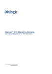
When a new call arrives, typically the application will need to initiate two listen commands as follows:
•
•
One command causes the resource to listen to the appropriate switch channel to hear the incoming voice
path.
The other command causes the T1/E1/J1 interface to listen to the output from the resource board to
generate the outgoing voice path.
Figure 1 shows the function of the commands.
Figure 1. Switch Connections
Switch
36
Dialogic® DSI SS7MD Programmer’s Manual Issue 3
4.8.2
Static Initialization
Static initialization is handled by the s7_mgt protocol configuration utility. For each T1/E1/J1 Line Interface
Unit (LIU), the user should include an LIU_SC_DRIVE command in the config.txt protocol configuration file.
The LIU_SC_DRIVE command has several parameters. The board_id and liu_id parameters together uniquely
identify the affected LIU. The sc_channel parameter is the channel number of the first channel on the switch
that is to be used for timeslots from the specified LIU. The ts_mask parameter is a mask identifying which
timeslots on the T1/E1/J1 interface are carrying voice circuits (as opposed to signaling) and therefore need
to be connected to the switch. The least significant bit of ts_mask should be 0 when driving from a T1/E1/J1
interface.
As an example, consider a two board system where the first board has four E1 ports and the second board
has four T1 ports (timeslots are numbered on a per board basis).
LIU_SC_DRIVE
LIU_SC_DRIVE
LIU_SC_DRIVE
LIU_SC_DRIVE
LIU_SC_DRIVE
LIU_SC_DRIVE
LIU_SC_DRIVE
LIU_SC_DRIVE
4.8.3
0
0
0
0
1
1
1
1
0
1
2
3
0
1
2
3
0 0xfffefffe * 30 E1 voice ccts on ts 1..15 & 17..31
30 0xfffefffe * 30 E1 voice ccts on ts 1..15 & 17..31
60 0xfffefffe * 30 E1 voice ccts on ts 1..15 & 17..31
90 0xfffefffe * 30 E1 voice ccts on ts 1..15 & 17..31
23 0x00fffffe * 23 T1 voice ccts on timeslots 1..23
46 0x00fffffe * 23 T1 voice ccts on timeslots 1..23
69 0x00fffffe * 23 T1 voice ccts on timeslots 1..23
72 0x00fffffe * 23 T1 voice ccts on timeslots 1..23
Dynamic Operation
The application controls dynamic changes to switching by sending the MVD_MSG_SC_LISTEN message to
the board. This message contains the liu_id (in the range 0 to one less than the number of LIUs), the
timeslot number on the T1/E1/J1 interface and the switch channel number (sc_channel) to which the
timeslot should listen. The message is directed to the correct board by calling the GCT_set_instance( )
function prior to calling the GCT_send( ) function.
When a new call arrives, the application will need to issue two listen commands (although they will not
necessarily both apply to the SS7 board). One connects the voice circuit in the forward direction and the
other connects voice circuit in the backward direction. See Figure 1 on page 36.
4.8.4
Example Code for Building and Sending MVD_MSG_SC_LISTEN Message
The following code demonstrates how to build and send an MVD_MSG_SC_LISTEN message to DSI SS7MD
Board to listen to a switch timeslot.
/*
* Example function for building and sending an MVD_MSG_SC_LISTEN
* message to an SS7 signaling card.
*
* The only change that the user needs to make is to fill in the
* OUR_MOD_ID definition below so that it is equal to the module_id
* of the application module.
*/
#define OUR_MOD_ID (0xef)
#include "system.h" /* Definitions of u8, u16 etc */
#include "msg.h" /* Definitions of HDR, MSG etc */
#include "libc.h" /* Used only for memset prototype */
#include "sysgct.h" /* Prototypes for GCT_xxx */
#include "pack.h" /* Prototypes for rpackbytes */
#include "ss7_inc.h" /* Message & module definitions */
/*
* Macro to generate the value for use in the rsp_req field of the
* message header in order to request a confirmation message:
*/
#define RESPONSE(module) (((unsigned short) 1) << ((module) & 0x0f))
/*
* Function to drive an SCbus / CT Bus timeslot
* onto a timeslot on a PCM port:
*/
int listen_to_scbus(board_id, liu_id, timeslot, sc_channel)
int board_id; /* board_id (0, 1, 2 ...) */
int liu_id; /* PCM port id (0 .. one less than no. of LIUs) */
int timeslot; /* Timeslot on the PCM port (1 .. 31) */
int sc_channel; /* SCbus / CT Bus channel number */
{
37
4 Dialogic® DSI SS7MD Board Configuration and Operation
MSG *m;
u8 *pptr;
/*
* Allocate a message (and fill in type, id, rsp_req & len):
*/
if ((m = getm(MVD_MSG_SC_LISTEN, 0, RESPONSE(OUR_MOD_ID), MVDML_SCLIS)) != 0)
{
pptr = get_param(m);
memset(pptr, 0, m->len);
/*
* Enter the parameters in machine independent format:
*/
rpackbytes(pptr, MVDMO_SCLIS_liu_id, (u32)liu_id, MVDMS_SCLIS_liu_id);
rpackbytes(pptr, MVDMO_SCLIS_timeslot, (u32)timeslot, MVDMS_SCLIS_timeslot);
rpackbytes(pptr, MVDMO_SCLIS_sc_channel, (u32)sc_channel, MVDMS_SCLIS_sc_channel);
m->hdr.dst = MVD_TASK_ID;
m->hdr.src = OUR_MOD_ID;
/*
* Call GCT_set_instance to route the message to the
* correct board and GCT_send to send the message.
* If GCT_send returns non-zero release the message.
*/
GCT_set_instance(board_id, (HDR *)m);
if (GCT_send(m->hdr.dst, (HDR *)m) != 0)
relm((HDR *)m);
}
return(0);
}
4.8.5
Interconnecting LIUs using STREAM_XCON
Interconnection of two Line Interface Units (LIUs) on the board is also supported through the STREAM_XCON
command which controls the cross connect switch on the signaling board, enabling the cross connection of
timeslots between any two LIUs within the board. This command simplifies the cross connection enabling a
group of timeslots on one LIU to be directly mapped to the same numbered timeslots on a second LIU on the
same board using a single command. A typical usage of the STREAM_XCON command is shown in Figure 2
which implements Drop and Insert functionality.
Figure 2. Drop and Insert
Stream A
- Media timeslots 1-15, 17- 31
- Signaling on timeslot16
Dialogic ® DSI
SS7MD Board
processes
signaling
timeslot16
Stream B
- Media timeslots 1-15, 17-31
connected to media board
Dialogic ®
DM3 Media Board
(e.g., Dialogic® DM/V1200BTEP
Media Board)
STREAM_XCON mode 3 “Duplex cross-connect the input and output timeslot”
Timeslot mask = 0xfffefffe
38
Dialogic® DSI SS7MD Programmer’s Manual Issue 3
4.9
Received Message Timestamping
Timestamping of received messages can be enabled for monitored links. This functionality provides a
timestamp of the time a message is received by a board. Individual boards maintain time by synchronising
with the host time.
The following table provides details of the expected timestamp accuracy between boards, in a multi board
system:
Operating System
4.9.1
Measured Accuracy
Linux
1 ms
Solaris
2 ms
Host Configuration
The host must be configured to enable timestamping as follows:
1. Configure the LIU to operate in high-impedance mode using the <liu_type> parameter in the
LIU_CONFIG command, which has the following format:
LIU_CONFIG <brd_id> <liu_id> <liu_type> <line_code> <frame_format> <crc_mode>
For example, to configure E1 high-impedance mode, use the command:
LIU_CONFIG 0 0 6 1 1 1
2. Configure receive only monitoring links using the MONITOR_LINK command in the config.txt file, which
has the following format:
MONITOR_LINK <link_id> <board_id> <blink> <stream> <timeslot> <user_module>
<filter> <flags> <phys_mask>
Timestamping is disabled by default. To enable timestamping on the monitored link, set bit 0 in the
<flags> field to 1. For example:
MONITOR_LINK 0 0 0 0 1 0xef 7 0x01 0xff
3. Configure the s7_log utility to display board and/or host timestamp information. See Section 8.1,
“s7_log” on page 162 for more information on the command line options for timestamping.
Note: To use the s7_log utility to display timestamps, monitoring messages must be redirected to the
s7_log module ID in the MONITOR_LINK command.
4.9.2
Timestamp Output
Once timestamping is enabled, a timestamped API_MSG_RX_INDT message is issued by the board instead of
an API_MSG_RX_IND message. These messages are sent to the user module configured in the
MONITOR_LINK command.
The following are examples of messages without timestamping enabled:
S7L:I0000 M t8f01 i0000 f00 def s00 pffff0103
S7L:I0000 M t8f01 i0000 f00 def s00 pffff0103
The following are examples of messages with timestamping enabled:
S7L:I0000 M t8f0f i0000 f00 def s00 pffff01037caa8ec4e90f2abf
S7L:I0000 M t8f0f i0000 f00 def s00 pffff01037caa8ec4c3976bbf
If the decoding of the timestamps is enabled in the s7_log utility, the output look like the following:
S7L:2001-11-20 15:17:01.012 BRD:2001-11-20 15:17:01.011 I0000 M t7e20 i0000 f0d def s00 p00030001006000
39
4 Dialogic® DSI SS7MD Board Configuration and Operation
4.10
High Speed Link Operation
High Speed Link (HSL) operation is supported in the following mode:
•
Structured mode, where the data stream is framed as for conventional SS7:
— For T1, 8 bits in each of 24 timeslots are available for signalling.
— For E1, timeslot 0 is used for framing and 31 timeslots are available for signaling.
The implementation supports the use of both 7-bit and 12-bit sequence numbers as a run-time configuration
option.
The DSI SS7MD Board will support up to 4 HSL links, dependent upon the licensing.
40
Dialogic® DSI SS7MD Programmer’s Manual Issue 3
4.11
Operation of the Thermal Sensor
Thermal Protection
The Dialogic® DSI SS7MDL4 Network Interface Board is a high performance, densely packed, low profile
PCIe board supporting high message rates. In achieving this performance, the board may dissipate up to
17W and this must be taken into consideration when selecting both the host chassis and the PCI Express slot
in which to install the board, refer to Appendix B, “Thermal guidelines for selecting suitable servers for use
with a Dialogic® DSI SS7MDL4 Network Interface Board.” In order to guard against hardware failure due to
inadequate cooling from the host chassis, the board is provided with an on-board thermal sensor which, in
the event that the board gets too hot, will shutdown the board.
Safety Threshold
The temperature of the boards within a system are periodically measured, and should the temperature of
any board exceed a fixed safety threshold then a warning will be provided to the host chassis that the
threshold has been passed, a MGT_MSG_EVENT_IND message with a status field of 0xc0 (Exceeded Thermal
Threshold) will be sent to SIU_MGT_TASK_ID (0xdf). If the board stays above this threshold limit for 30
minutes, but does not exceed the temperature at which the board shuts down, a subsequent
MGT_MSG_EVENT_IND will be generated. A new MGT_MSG_EVENT_IND message will be generated after
each 30 minutes period whilst this condition is maintained.
Thermal Shutdown
If the temperature of the board continues to rise, a second threshold will be passed at which, to protect the
hardware, the board will be shutdown. On reaching this Thermal Shutdown threshold, the user will be
notified via a Board Status Indication (SSD_MSG_STATE_IND) message with a status field of 0x62 (Board
Failure) and a failure code parameter set to 0xd7. A MGT_MSG_EVENT_IND message with a status field of
0xd7 (Shutdown due to Thermal Issues) will also be sent.
Once these messages have been sent, all outstanding messages and all subsequently received messages
destined for the board will be discarded.
Reset after Thermal Shutdown
Once the board is shutdown, power can only be restored by a full power cycle of the board.
41
4 Dialogic® DSI SS7MD Board Configuration and Operation
42
Dialogic® DSI SS7MD Programmer’s Manual Issue 3
Chapter 5: Program Execution
This chapter describes how to start the software and execute programs. It assumes that:
•
•
•
The software has already been installed. Refer to Chapter 3, “Installation”.
The system.txt configuration file has been modified correctly. Refer to Section 4.4, “System Configuration”
on page 29.
The config.txt protocol configuration file has been modified correctly. Refer to Section 4.5, “Protocol
Configuration” on page 32.
It contains the following sections:
•
•
Program Execution Overview
Program Execution Under Linux and Solaris
43
5 Program Execution
5.1
Program Execution Overview
There are three main stages to getting a new application up and running, although the precise means of
achieving this vary slightly depending upon the operating system:
1. Ensure that the device driver is installed and running.
2. Ensure that the protocol software is running on the host.
3. Write your application (making use of the examples supplied), compile it (using the header files supplied)
and link it with the supplied libraries to generate a finished application program.
The details of how these steps are achieved for each supported operating system are described in the
following topic:
•
44
Program Execution Under Linux and Solaris
Dialogic® DSI SS7MD Programmer’s Manual Issue 3
5.2
Program Execution Under Linux and Solaris
Proceed as follows:
1. Ensure the device driver has been installed and the system.txt configuration file has been modified in
accordance with system requirements to select the correct protocols etc.
2. Ensure that the correct codefile has been copied into the directory containing all the SS7 binaries.
3. If using the s7_mgt protocol configuration utility, ensure that the config.txt protocol configuration file has
been edited to provide the correct protocol configuration.
4. Start the software by changing to the directory containing all the SS7 binaries and running the gctload
program optionally specifying the system configuration file with the -c option
a. To run the system in the foreground, enter:
gctload -csystem.txt
b. To run the system in the background, enter:
gctload -csystem.txt &
The gctload program initializes the system environment and starts other processes. The s7_mgt process
configures all the protocol modules. A banner confirms that the system is running.
5. Activate and deactivate signaling links, if required, using the mtpsl example utility as follows:
mtpsl {act | deact} <linkset_id> <link_ref>
mtpsl act 0 0
mtpsl deact 0 0
6. Shutdown the host software by running the gctload program using the –x option
gctload –x
Any modules that have been started by the gctload program are terminated automatically.
45
5 Program Execution
46
Dialogic® DSI SS7MD Programmer’s Manual Issue 3
Chapter 6: Message Reference
This section describes the individual messages that may be sent to or received from a Dialogic® DSI SS7MD
Board. Some messages are sent by the user's application software, while others are sent by utility programs
such as the s7_mgt protocol configuration utility.
Prior to sending any message to the board, the application should call the GCT_set_instance( ) library
function to select which board the message will be sent to. After receiving a message from the board, the
application should call the GCT_get_instance( ) library function to determine which board the message
came from. These library functions are described in the Software Environment Programmer's Manual.
The various messages used are grouped in the following categories:
•
•
•
•
•
•
•
General Configuration Messages
Hardware Control Messages
Signaling Interface Messages
ATM Interface Messages
Q.SAAL Module
Event Indication Messages
Status Request Messages
Table 7, “Message Summary” on page 115 provides a summary of all messages. The message header for all
messages has the same general format. See the Message Format appendix in the Software Environment
Programmer’s Manual for more information.
47
6 Message Reference
6.1
DSI SS7MD Software Module IDs for DSI SS7MD Board
Table 6 lists the software modules IDs (by mnemonic and value) used on the DSI SS7MD Board.
Table 6. DSI SS7MD Board Software Module IDs
Mnemonic
48
Value
Description
MGMT_TASK_ID
0x8e
SS7MD Board Management Module
MVD_TASK_ID
0x10
SS7MD LIU and Switch Management Module
SS7_TASK_ID
0x71
MTP2 Module
DVR_ALT_TASK_ID
0x61
Signaling Driver Module
ATM_TASK_ID
0x31
ATM Module
QSL_TASK_ID
0x41
Q.SAAL Module
Dialogic® DSI SS7MD Programmer’s Manual Issue 3
6.2
General Configuration Messages
General configuration messages are typically issued by the s7_mgt protocol configuration utility, in which case
they need not, and should not, be generated by any user application software.
If the user elects not to use the s7_mgt protocol configuration utility, it is necessary for the application to
build and send messages that:
•
•
•
•
configure the ssd module
reset each board
configure each board
optionally configure additional routes
The messages in the general configuration category include:
•
•
•
•
•
•
•
SSD_MSG_RESET - SSD Reset Request
SSD_MSG_RST_BOARD - Board Reset Request
SSD_MSG_BOARD_INFO - Board Information Request
MGT_MSG_CONFIG0 - Board Configuration Request
MGT_MSG_L1_CONFIG - Layer 1 Configuration Request
MGT_MSG_L1_END - Layer 1 Configuration End
MGT_MSG_NTP_CONFIG - Network Time Configuration
6.2.1
SSD_MSG_RESET – SSD Reset Request
Synopsis
Sets up ssd module run-time options at initialization time.
Note: When using the s7_mgt protocol configuration utility, this message is generated by s7_mgt and
should not be generated by the user.
Format
MESSAGE HEADER
Field Name
Meaning
type
SSD_MSG_RESET (0x7680)
id
0
src
Sending module ID
dst
SSD_module_ID
rsp_req
Used to request a confirmation.
hclass
0
status
0
err_info
0
len
24
PARAMETER AREA
Offset
Size
Name
0
1
Reserved. Set to 0.
1
2
Reserved. Set to 0.
3
1
mgmt_id
4
18
Reserved. Set to 0.
22
2
num_boards
Description
This message is used during initialization by the application to reset the ssd module and set up its run-time
parameters.
The confirmation message (if requested) indicates success with a status value of 0.
49
6 Message Reference
Parameters
The SSD_MSG_RESET message includes the following parameters:
•
•
mgmt_id
The module ID of the management module to which SSD should send board status indications.
num_boards
The maximum number of boards that ssd is required to manage. This should not exceed 4.
6.2.2
SSD_MSG_RST_BOARD – Board Reset Request
Synopsis
Reset a single board and download a codefile.
Note: When using the s7_mgt protocol configuration utility, this message is generated by s7_mgt and
should not be generated by the user.
Format
MESSAGE HEADER
Field Name
Meaning
type
SSD_MSG_RST_BOARD (0x7681)
id
board_id
src
Sending module ID
dst
SSD_module_ID
rsp_req
Used to request a confirmation.
hclass
0
status
0
err_info
0
len
26
PARAMETER AREA
Offset
0
Size
2
Name
board_type
2
4
Reserved. Must be set to 0.
6
18
code_file
24
2
run_mode
Description
This message is used by the application during initialization (or reconfiguration) to reset a board and
download the codefile that contains the operating software for the board. The download operation is
supervised by the device driver that reads the binary format codefile and transfers it to the board.
The confirmation message (if requested) indicates success with a status value of 0. This implies that the
reset operation has commenced, but does not imply completion. The application should then wait until a
Board Status Indication message is received that indicates either successful completion of the reset and
download operation or failure during the procedure.
Parameters
The SSD_MSG_RST_BOARD message includes the following parameters:
•
•
50
board_type
The type of board to be reset. This must be set to 16 for DSI SS7MD Boards.
code_file
Null terminated string giving the filename of the codefile to be downloaded to the board.
Dialogic® DSI SS7MD Programmer’s Manual Issue 3
•
run_mode
The protocols to be run. The following table shows the permitted values and their meaning.
Value
Run Mode
Protocols Selected to Run on the Board
34
LSL
MTP2 Low Speed Links
35
HSL
MTP2 High Speed Links
36
ATM
ATM links
37
IMA
Inverse Multiplexed ATM links
The following combinations of link types are available to the user.
Run
Mode
LSL Links
HSL Links
ATM Links
LSL
Y
Y
Y
HSL
Y
Y
Y
ATM
Y
Y
IMA
IMA Links
Y
Y
Y
Note: When using multiple link types on the same board, the run mode indicates to the board the
predominant link type.
Note: It is only possible to activate protocols that have been licensed to run on the board by use of a
suitable host licenses.
51
6 Message Reference
6.2.3
SSD_MSG_BOARD_INFO – Board Information Request
Synopsis
Message used to retrieve information about the DSI SS7MD Board.
Format
MESSAGE HEADER
Field Name
Meaning
type
SSD_MSG_BOARD_INFO (0x7689)
id
board_id
src
Sending module ID
dst
SSD_module_ID
rsp_req
Used to request a confirmation.
Hclass
0
Status
0
err_info
0
Len
38
PARAMETER AREA
Offset
Size
Name
0
4
ssd_mode
4
2
board_type
6
10
Reserved. Must be set to 0.
16
20
serial_number
36
1
current_temp
37
1
max_temp
Description
This message is used when a user application wants to obtain information about a DSI SS7MD Board. This
can happen at any time after the board has been reported as being present in the system. Typically, in PCI
address mode (see ssd_mode below), this message may be sent by the user application to the ssdm module
at system startup to determine the serial numbers of boards present within the system.
In the Serial number address mode (see ssd_mode below) this message may be sent by the user application
to determine the serial numbers of boards present in the system either via their logical geographic address
(see Section 8.7.1, “Geographic Addressing” on page 173) or their physical address (see Section 8.7.1,
“Geographic Addressing” on page 173).
Parameters
The SSD_MSG_BOARD_INFO message includes the following parameters:
•
•
board_id
The board_id should be set to the logical board number or alternatively, if geographic addressing is
enabled, to the board’s physical address (see Section 8.7.1, “Geographic Addressing” on page 173).
ssd_mode
Specifies the geographic address mode in which the ssdm module is running. This was specified at
system start-up.
The geographic address modes values are:
— 1: PCI address mode
— 2: Serial number address mode
•
•
52
board_type
The board type. For DSI SS7MD Boards, this parameter is set to 16.
serial_number
The serial number of the board.
Dialogic® DSI SS7MD Programmer’s Manual Issue 3
•
•
current_temp
Signed 8-bit value containing the current temperature of the board within the range -128 to 127 degrees
Celsius.
max_temp
Signed 8-bit value containing the maximum temperature the board has reached since SSDM was last
started. Value is within the range -128 to 127 degrees Celsius.
6.2.4
MGT_MSG_CONFIG0 – Board Configuration Request
Synopsis
Message sent to a board immediately after starting the code running to provide physical configuration
parameters.
Note: When using the s7_mgt protocol configuration utility, this message is generated by s7_mgt and
should not be generated by the user.
Format
MESSAGE HEADER
Field Name
Meaning
type
MGT_MSG_CONFIG0 (0x7f10)
id
0
src
Sending module ID
dst
MGMT_module_ID
rsp_req
Used to request a confirmation.
hclass
0
status
0
err_info
0
len
68
PARAMETER AREA
Offset
Size
Name
0
2
config_type
2
2
flags
4
2
l1_flags
6
62
Reserved. Must be set to 0.
Description
This message must be the first message sent to the board once the SS7 software is running. It is used to
configure layer1 modules on the board for operation. The message contains flags to permit various level 1
configurations. The physical link parameters are configured on a per link basis using the
MGT_MSG_L1_CONFIG command.
The confirmation message (if requested) indicates success with a status value of 0. To ensure that
configuration is complete before subsequent messages are issued to the board, the user should always
request a confirmation message and check the status for success.
If the board is not licensed to run the requested software configuration, a status value of 0xfe is returned.
Parameters
The MGT_MSG_CONFIG0 message includes the following parameters:
•
•
config_type
Set to 3 when using a DSI SS7MD Board. A separate link layer configuration message should be sent for
each link using the MGT_MSG_L1_CONFIG message.
flags
Global flags with the following bit significance:
53
6 Message Reference
— Bit 15 is set to 1 for diagnostics purposes to cause the results of board configuration to be passed to
the host. When set, all confirmation messages generated internally on the board during the
configuration sequence are sent to the 0xdf module ID on the host.
— All other bits are reserved for future use and should be set to 0.
•
l1_flags
Level 1 flags with the following bit significance:
— Bit 0 controls the layer 1 clock reference source. If set to 0, the clock is recovered from the onboard
oscillator. If set to 1, the clock is recovered from one of the line interfaces. Line interfaces can be
individually configured with the LIU_MSG_CONFIG message to explicitly be excluded from recovering
the clock from the interface.
— All other bits are reserved and should be set to 0.
6.2.5
MGT_MSG_L1_CONFIG – Layer 1 Configuration Request
Synopsis
Message sent to a board after successful processing of the MGT_MSG_CONFIG0 message to configure the
layer 1 links.
Note: When using the s7_mgt protocol configuration utility, this message is generated by s7_mgt and
should not be generated by the user.
Format
MESSAGE HEADER
Field Name
Meaning
type
MGT_MSG_L1_CONFIG (0x7f17)
id
0
src
Sending module's module ID
dst
MGMT_module_ID
rsp_req
Used to request a confirmation.
hclass
0
status
0
err_info
0
len
40
PARAMETER AREA
Offset
Size
Name
0
2
Reserved. Set to 0.
2
2
4
2
data_rate
6
2
link_source
8
2
Reserved. Set to 0.
10
2
Reserved. Set to 0.
l1_resource_id
12
2
link_stream
14
2
link_timeslot
16
2
Reserved. Set to 0.
18
2
Reserved. Set to 0.
20
4
options
24
4
timeslot_mask
28
12
Reserved. Set to 0.
Description
This message is used after successful processing of the MGT_MSG_CONFIG0 message to configure physical
signaling links. It should only be sent after the MGT_MSG_CONFIG0 message has been sent. The message
should be sent once for each signaling link to be configured.
Parameters
The MGT_MSG_L1_CONFIG message includes the following parameters:
54
Dialogic® DSI SS7MD Programmer’s Manual Issue 3
Configure the LSL timeslot rate:
•
•
•
•
•
l1_resource_id
Layer 1 (logical) resource identifier.
data_rate
Used for setting the link operation. The following table shows the permitted values and their meaning.
Value
Data Rate
0
64 kbits/s
1
56 kbits/s
2
48 kbits/s
link_source
Configure the signaling source.
Set to 0 for DSI SS7MD Board.
link_stream
Signaling stream. This parameter is the physical identity of the T1/E1/J1 line interface containing the
signaling link. The value range is 0 to one less than the number of LIUs.
link_timeslot
Signaling timeslot. This field is used to configure conventional SS7 links. The value ranges for
link_timeslot are:
— For a T1 interface: 1 to 24.
— For an E1 interface: 1 to 31.
— For a J1 interface: 1 to 24.
•
options
A 32-bit value containing run-time options as follows:
— Bit 0 - Set to 1 to disable automatic FISU generation. This is normally required for Japanese MTP
operation only.
— Bit 1 - Set to 1 to enable onboard time stamping on monitored links. Setting this bit changes the
MSG type of the monitor message from API_MSG_RX_IND to API_MSG_RX_INDT.
— Bit 4 - HSL operation. Set to 0 for 7-bit sequence numbers. Set to 1 for 12-bit sequence numbers.
— Bit 6 - HSL operation. Set to 0 for LSL SS7. Set to 1 for HSL SS7.
— All Other Bits - Must be set to 0.
•
timeslot_mask
Signaling timeslot mask. This field is used to configure HSL links. Bits 0 to 31 of the mask correspond to
timeslots 0 to 31 of the signaling stream identified by the link_stream parameter. The recommended
bits masks values are:
Value
Description
0xfffffffe
structured E1 HSL, 31 slots (1 to 31)
0x01fffffe
structured T1 HSL, 24 slots (1 to 24)
0xfffefffe
structured E1 HSL, 30 slots (1 to 15,17 to 31)
55
6 Message Reference
6.2.6
MGT_MSG_L1_END – Layer 1 Configuration End
Synopsis
Message sent to a board to remove an existing layer 1 link that was previously configured by sending an
MGT_MSG_L1_CONFIG message.
Format
MESSAGE HEADER
Field Name
Meaning
type
MGT_MSG_L1_END (0x7f18)
id
0
src
Sending module's module ID
dst
MGMT_module_ID
rsp_req
Used to request a confirmation.
hclass
0
status
0
err_info
0
len
4
PARAMETER AREA
Offset
Size
0
2
2
2
Name
Reserved. Must be set to 0.
l1_resource_id
Parameters
The MGT_MSG_L1_END message includes the following parameters:
•
l1_resource_id
Layer 1 (logical) resource identifier.
6.2.7
MGT_MSG_NTP_CONFIG – Network Time Configuration
Synopsis
Configures network-specific time parameters.
Format
MESSAGE HEADER
Field Name
Meaning
type
MGT_MSG_NTP_CONFIG (0x7f0d)
id
0
src
Sending module's module ID
dst
MGMT_TASK_ID
rsp_req
Used to request a confirmation
class
0
status
0
err_info
0
len
8
PARAMETER AREA
Offset
Size
Name
0
2
enable
2
2
poll_interval
4
4
ntp_management_id
Description
This message is issued to the signaling processor MGMT module by the host application to enable or disable
timestamping, specify the poll interval and communicate host NTP server module ID.
56
Dialogic® DSI SS7MD Programmer’s Manual Issue 3
Parameters
The MGT_MSG_NTP_CONFIG message includes the following parameters:
•
•
•
enable
Set to 1 to enable timestamping, 0 to disable timestamping.
poll_interval
Set to 4.
ntp_management_id
Set to 0x20.
57
6 Message Reference
6.3
Hardware Control Messages
Hardware control messages are used to control various hardware devices on the board, including the T1/E1/
J1 Line Interface Units (LIUs), the digital cross connect switches and the clocking mode for the board.
In a static configuration, these hardware blocks can be set up using the s7_mgt protocol configuration utility
along with the appropriate commands in the config.txt protocol configuration file.
If dynamic control of the hardware is required (or the user has elected not to use s7_mgt), the user
application must build and send at least some of the hardware control messages.
The messages in the hardware control category include:
•
•
•
•
•
•
•
•
•
58
LIU_MSG_CONFIG - LIU Configuration Request
LIU_MSG_CONTROL - LIU Control Request
LIU_MSG_R_CONFIG - LIU Read Configuration Request
LIU_MSG_R_CONTROL - LIU Read Control Request
MVD_MSG_RESETSWX - Reset Switch Request
MVD_MSG_SC_CONNECT - Connect Request
MVD_MSG_SC_MULTI_CONNECT - Multiple Connect Request
MVD_MSG_SC_DRIVE_LIU - LIU Switch Initialization
MVD_MSG_SC_LISTEN - Cross Connect Switch Listen Request
Dialogic® DSI SS7MD Programmer’s Manual Issue 3
6.3.1
LIU_MSG_CONFIG – LIU Configuration Request
Synopsis
Message sent by the application to establish the operating mode for a Line Interface Unit (LIU).
Note: When using the s7_mgt protocol configuration utility, this message is generated by s7_mgt as a
result of the LIU_CONFIG command. It therefore need not be generated by the user.
Format
MESSAGE HEADER
Field Name
Meaning
type
LIU_MSG_CONFIG (0x7e34)
id
liu_id (in the range 0 to one less than the number of LIUs)
src
Sending module ID
dst
MVD_module_ID
rsp_req
Used to request a confirmation.
hclass
0
status
0
err_info
0
len
40
PARAMETER AREA
Offset
Size
Name
0
1
liu_type
1
1
liu_code
2
1
frame_format
3
1
crc_mode
4
1
build_out
5
6
Reserved. Must be set to 0.
11
1
ais_gen
12
6
Reserved. Must be set to 0.
18
1
high_Z
19
2
clk_options
21
19
Reserved. Must be set to 0.
Description
This message is sent to the board to configure the operating mode of a Line Interface Unit (LIU). All
configuration parameters must be supplied in the message, that is, it is not possible to modify individual
operating parameters in isolation. On receipt of the message, the board first verifies that the fitted hardware
options support the requested operating mode and then initializes (or reinitializes) the LIU.
The confirmation message (if requested) indicates success with a status value of 0.
Parameters
A description of the permitted parameter values are given below. When the board is initially configured, the
LIUs are initialized to a disabled condition. The LIU_MSG_CONFIG message includes the following
parameters:
•
liu_type
The physical interface type according to the following table. The preferred method for configuring an E1
interface is to set a value of 5.
Value
1
Description
Disabled (used to deactivate a LIU). In this mode, the LIU does not produce an
output signal.
59
6 Message Reference
3
E1 120 ohm balanced interface
4
T1 (including J1)
5
E1 120 ohm balanced interface
Note: The option chosen by the user must be appropriate to the actual hardware fitted; otherwise an
error status is returned.
•
line_code
The line coding technique. The following table shows the permitted values and their meanings.
Value
•
Description
1
HDB3 (E1 only)
2
AMI
4
B8ZS (T1/J1)
frame_format
The frame format. The following table shows the permitted values and their meanings.
Value
•
Description
1
E1 double frame (E1 only)
2
E1 CRC4 multiframe (E1 only)
3
F4 4-frame multiframe (T1 only)
4
D3/D4 (Yellow alarm = bit 2 in each channel (T1 only)
7
ESF (Yellow alarm in data link channel) (T1 only)
8
F72/SLC96 (72-frame multiframe) (T1 only)
9
J1 frame format (liu_type must be 4 [T1])
crc_mode
The CRC mode. The following table shows the permitted values and their meanings.
Value
•
Description
1
CRC generation disabled
2
CRC4 enabled (frame_format must be set to 2)
4
CRC6 enabled (frame_format must be set to 7)
build_out
The following table shows the permitted values and their meanings.
Value
60
Description
0
Setting for E1 devices
1
T1 default (T1 short haul)
2
T1 short haul 0 - 133 ft
3
T1 short haul 133 - 266 ft
4
T1 short haul 266 - 399 ft
5
T1 short haul 399 - 533 ft
6
T1 short haul 533 - 655 ft
7
Not supported.
8
T1 long haul LB0 (-0dB)
9
T1 long haul LB0 (-7.5dB)
Dialogic® DSI SS7MD Programmer’s Manual Issue 3
10
•
T1 long haul LB0 (-15dB)
11
Not supported.
12
T1 long haul LBO (-22.5dB)
ais_gen
The (initial) mode used to generate the Alarm Indication Signal (Blue alarm). The user may subsequently
modify the setting of the outgoing signal using the LIU_MSG_CONTROL message. The following table
shows the permitted values and their meanings.
Value
•
Description
1
Disabled; do not generate AIS/Blue alarm
2
Enabled; generate AIS/Blue alarm
high_Z
The mode settings to allow interface high impedance for monitoring purposes. The following table shows
the permitted values and their meanings.
Value
•
Description
1
Disabled; normal impedance presented on the line
2
Enabled; set the LIU to high impedance for monitoring
clk_options
A 16-bit value containing clocking options for the LIU. This value provides the ability to override default
LIU clocking options for each LIU. Default options are specified per board within the MGT_MSG_CONFIG0
message.
— Bit 0 - Disable LIU clock recovery for this interface.
— All other bits set to 0.
61
6 Message Reference
6.3.2
LIU_MSG_CONTROL – LIU Control Request
Synopsis
Message sent by the application to dynamically control operation for a Line Interface Unit (LIU). Allows
setting of outgoing alarms and diagnostic loopbacks.
Format
MESSAGE HEADER
Field Name
Meaning
type
LIU_MSG_CONTROL (0x7e35)
id
liu_id (in the range 0 to one less than the number of LIUs)
src
Sending module ID
dst
MVD_module_ID
rsp_req
Used to request a confirmation.
hclass
0
status
0
err_info
0
len
16
PARAMETER AREA
Offset
Size
Name
0
1
ais_gen
1
1
Reserved for future use, must be set to 0.
2
1
loop_mode
3
1
Reserved for future use, must be set to 0.
4
1
prbs_gen
5
11
Reserved for future use, must be set to 0.
Description
This message is sent to the board to perform dynamic changes to the operation of the Line Interface Unit
(LIU). It allows the user to control the generation of AIS (Blue alarm) and to activate various diagnostic
loopback modes. It also allows the configuration of PRBS test sequences.
The confirmation message (if requested) indicates success with a status value of 0.
Parameters
The LIU_MSG_CONTROL message includes the following parameters:
•
ais_gen
The mode used to generate the Alarm Indication Signal (Blue alarm). The following table shows the
permitted values and their meanings.
Value
62
Description
0
Do not change AIS/Blue alarm generation mode
1
Disabled; do not generate AIS/Blue alarm
2
Enabled; generate AIS/Blue alarm
Dialogic® DSI SS7MD Programmer’s Manual Issue 3
•
loop_mode
The diagnostic loopback mode. The following table shows the permitted values and their meanings.
Value
•
Description
0
Do not change diagnostic loopback mode
1
Disabled - remove any diagnostic loop
2
Payload loopback
3
Remote loopback
4
Local loopback
prbs_gen
The Pseudo Random Bit Sequence (PRBS) generation mode. The following table shows the permitted
values and their meanings.
Value
6.3.3
Description
0
Do not change PRBS generation mode
1
Disabled - remove any PRBS generation
3
Generate PRBS pattern QRSS 20
LIU_MSG_R_CONFIG – LIU Read Configuration Request
Synopsis
Message sent by the application to read back the current LIU configuration from the board.
Format
MESSAGE HEADER
Field Name
Meaning
type
LIU_MSG_R_CONFIG (0x5e37)
id
liu_id (in the range 0 to one less than the number of LIUs)
src
Sending module ID
dst
MVD_module_ID
rsp_req
Used to request a confirmation.
hclass
0
status
0
err_info
0
len
40
PARAMETER AREA
Offset
0
Size
40
Name
Parameter area formatted in the same manner as the
LIU_MSG_CONFIG message.
All fields should be set to 0.
The confirmation message contains the board configuration details.
The user should set the fields to 0 and the module writes the current
configuration parameters in the confirmation message.
Description
This message is sent to the board to read back the current operating configuration of the Line Interface Unit
(LIU). The user should always request a confirmation message. The confirmation message indicates success
with a status value of 0 and contains the current configuration parameters in the parameter area of the
message.
63
6 Message Reference
6.3.4
LIU_MSG_R_CONTROL – LIU Read Control Request
Synopsis
Message sent by the application to read back the current Line Interface Unit (LIU) control options from the
board.
Format
MESSAGE HEADER
Field Name
Meaning
type
LIU_MSG_R_CONTROL (0x5e38)
id
liu_id (in the range 0 to one less than the number of LIUs)
src
Sending module ID
dst
MVD_module_ID
rsp_req
Used to request a confirmation.
hclass
0
status
0
err_info
0
len
16
PARAMETER AREA
Offset
0
Size
16
Name
Parameter area formatted in the same manner as the
LIU_MSG_CONTROL message.
All fields should be set to 0. The confirmation message contains LIU
control options.
The user should set the fields to 0 and the module writes the current
control parameters in the confirmation message.
Description
This message is sent to the board to read back the current control parameters selected for a Line Interface
Unit (LIU). The user should always request a confirmation message. The confirmation message indicates
success when the status value of 0 and contains the current control parameters in the parameter area of the
message.
6.3.5
MVD_MSG_RESETSWX – Reset Switch Request
Synopsis
Resets the digital switch to its default state in accordance with the current board configuration.
Format
MESSAGE HEADER
Field Name
type
Meaning
MVD_MSG_RESETSWX (0x7e00)
id
0
src
Sending module ID
dst
MVD_module_ID
rsp_req
Used to request a confirmation.
hclass
0
status
0
err_info
0
len
0
Description
This message is sent to the board to reset the state of the digital cross connect switch.
64
Dialogic® DSI SS7MD Programmer’s Manual Issue 3
The confirmation message (if requested) indicates success with a status value of 0. On receipt of the
confirmation message, the operation to reset the switch is completed.
6.3.6
MVD_MSG_SC_CONNECT – Connect Request
Synopsis
Message sent to the board to control the switch path.
Format
MESSAGE HEADER
Field Name
Meaning
type
MVD_MSG_SC_CONNECT (0x7e1f)
id
0
src
Sending module ID
dst
MVD_module_ID
rsp_req
Used to request a confirmation.
hclass
0
status
0
err_info
0
len
16
PARAMETER AREA
Offset
Size
0
2
local_stream
Name
2
2
local_slot
4
2
mode
6
2
source_stream
8
2
source_slot
10
2
dest_stream
12
2
dest_slot
14
2
Reserved. Must be set to 0.
Description
This message is sent to the board to control the cross connect switch. Several different actions can be
performed depending on the value of the mode parameter. These include:
•
•
•
•
Cross connect switch to CPU local bus stream connection
Local bus to cross connect switch connection
Duplex connection between cross connect switch and CPU local bus stream
Duplex connection between local bus timeslots
Attempting to use this message in a run mode where the cross connect switch is disabled will result in a
failure return code.
The confirmation message (if requested) indicates success with a status value of 0.
65
6 Message Reference
Parameters
The parameters that can be included in the MVD_MSG_SC_CONNECT message depend on the requested
mode. The following table depicts the parameters that are required for each possible mode:
Required Parameters
Mode
1
local_
stream
local_slot
source_
stream
source_
timeslot
dest_
stream
dest_
timeslot
pattern
*1
*1
*
*
0
0
0
2
*
*
0
0
*
*
0
3
*1
*1
*
*
*
*
0
4
*1
*1
0
0
0
0
0
5
*
*
0
0
0
0
0
6
*1
*1
0
0
0
0
0
8
*1
*1
*
*
0
0
0
1
1
11
*
*
*
0
0
0
12
*1
*
*1
*1
*1
0
0
0
13
*1
*1
*1
*1
0
0
0
* indicates that the parameter is required,
•
•
66
indicates that CPU local bus stream values are invalid.
local_stream
Defines which local stream to use for all the modes of operation.The local_stream parameter specifies
either a T1/E1/J1 Line Interface Unit (LIU) or CPU local bus stream. Values for the LIU are in the range 0
to one less than the number of LIUs supported. CPU local bus stream values are in the range 0x90
upwards, the number of CPU local bus streams are one less then the number of LIUs supported.
local_slot
Defines which timeslot on the local stream to use for all the modes of operation. The local slot value has
different valid ranges depending on the local stream type. The following table shows the permitted
values and their meanings.
Local Stream Type
•
1
Local Slot Range
Local stream to E1 LIU
1 to 31
Local stream to T1 LIU
1 to 24
Local stream to CPU
1 to 31
mode
Determines the operating mode. The following table shows the permitted values and their meanings.
Value
Meaning
1
Make a simplex connection from a timeslot on the cross connect switch to a
timeslot on the local bus. Use the local_stream, local_slot, source_stream, and
source_slot parameters to specify the local and switch timeslots, respectively.
2
Make a simplex connection from a timeslot on the CPU local bus stream to a
timeslot on the cross connect switch. Use the local_stream, local_slot,
dest_stream, and dest_slot parameters to specify the local and switch
timeslots, respectively.
3
Make a duplex connection between a CPU local bus stream timeslot and two
cross connect switch timeslots. Use the local_stream, local_slot, source_stream,
and source_slot parameters to specify one simplex connection; and the
local_stream, local_slot, dest_stream, and dest_slot parameters to specify the
other simplex connection.
4
Remove a simplex connection from a timeslot on the cross connect switch to a
timeslot on the CPU local bus. Use the local_stream and local_slot parameters
to specify the timeslot for disconnection.
5
Remove a simplex connection from a timeslot on the CPU local bus to a timeslot
on the cross connect. Use the local_stream and local_slot parameters to specify
the timeslot for disconnection.
Dialogic® DSI SS7MD Programmer’s Manual Issue 3
•
•
•
•
Value
Meaning
6
Remove a duplex connection between two timeslots on the cross connect switch
and one timeslot on the CPU local bus. Use the local_stream and local_slot
parameters to specify both timeslots for disconnection.
8
Remove a connection between a switch timeslot and a CPU local bus timeslot.
Then create a simplex connection between the same CPU local bus timeslot
back to the switch timeslot. Use the local_stream and local_slot parameters to
specify the CPU local bus timeslot, and the source_stream and source_timeslot
to specify the switch timeslot.
11
Make a simplex connection between two CPU local bus timeslots. The
source_stream and source_slot parameters specify the source of the signal in
terms of liu_id and timeslot, respectively. The local_stream and local_slot
parameters specify the outgoing lLIU or CPU stream and timeslot, respectively.
12
Make a duplex connection between two CPU local bus timeslots. The
source_stream and source_slot parameters specify the source of the signal in
terms of liu_id and timeslot, respectively. The local_stream and local_slot
parameters specify the outgoing liu_id and timeslot, respectively
13
Remove a duplex connection between two CPU local bus timeslots. Use the
local_stream and local_slot parameters to specify one timeslot and the
source_stream and source_slot parameters to specify the other.
source_stream
The source_stream references the cross connect switch streams that should be used as a source for
data. The parameter takes values in the range of 0 to 31. For some modes (for example, 11 and 12), this
field is used to specify a local stream instead of a switch stream.
source_slot
The source slot references the timeslot from which to connect or disconnect to the cross connect switch
stream. The source slot values are in the range 0 to 127.
dest_stream
The dest_stream references the cross connect switch streams that should be used as a destination for
data. The parameter takes values in the range of 0 to 31.
dest_slot
The dest slot references the timeslot from which to connect or disconnect to the cross connect switch
stream. The dest slot values are in the range of 0 to 127.
67
6 Message Reference
6.3.7
MVD_MSG_SC_MULTI_CONNECT – Multiple Connect Request
Synopsis
Message sent to the board to control the switch to connect multiple paths.
Format
MESSAGE HEADER
Field Name
Meaning
type
MVD_MSG_SC_MULTI_CONNECT (0x7e19)
id
0
src
Sending module ID
dst
MVD_module_ID
rsp_req
May be used to request a confirmation.
hclass
0
status
0
err_info
0
len
18
PARAMETER AREA
Offset
Size
Name
0
2
local_stream
2
4
timeslot_mask
6
2
mode
8
2
source_st
10
2
source_ts
12
6
Reserved. Must be set to 0.
Description
This message is sent to the board in order to control the configuration of the cross connect switch for more
complex configurations.
Parameters
The MVD_MSG_SC_MULTI_CONNECT message includes the following parameters:
•
•
•
local_stream
The logical reference of the local stream that the message relates to, that is, 0 to one less than the
number LIUs corresponding to the liu_id.
timeslot_mask
A 32-bit mask representing up to 32 timeslots on the local stream. Bit 0 corresponds to timeslot 0. A 1 in
the mask indicates that the pattern should be output on this timeslot, a 0 indicates that it should be left
unchanged.
mode
The mode of operation. The following table shows the permitted values and their meaning.
Value
1
11
68
Description
Make a simplex connection between an cross connect switch timeslot and a local
LIU stream. Use the local_stream and timeslot_mask to specify the target
destination on the CPU local bus. The source_st and source_ts.
Make a simplex connection between two CPU local bus stream timeslots. The
source_st and source_ts parameters specify the source of the signal in terms of
liu_id or CPU local bus stream reference and timeslots, respectively. The
local_stream relates to the outgoing liu_id stream and cannot reference a CPU local
bus stream. The timeslot_mask parameters specify the outgoing timeslots to which
the source will be connected.
Dialogic® DSI SS7MD Programmer’s Manual Issue 3
•
source_st, source_ts
When mode is set to 11, these parameters give the source_st and source_ts for connection to the
specified local timeslots. For other modes the source_st and source_ts specify the cross connect switch
stream and timeslot, respectively.
6.3.8
MVD_MSG_SC_DRIVE_LIU – LIU Switch Initialization
Synopsis
Sets up a static switch path through the board between a CPU local bus timeslot and a switching channel.
Format
MESSAGE HEADER
Field Name
Meaning
Type
MVD_MSG_SC_DRIVE_LIU (0x7e18)
Id
0
Src
Sending module's Id
Dst
MVD_TASK_ID
Rsp_req
Used to request a confirmation
Hclass
0
Status
0
Err_info
0
Len
10
PARAMETER AREA
Offset
Size
Name
0
2
liu_id
2
2
sc_channel
4
4
ts_mask
8
2
mode
Description
This message is sent to connect selected CPU local bus timeslots from an T1/E1/J1 LIU or CPU stream to a
block of cross connect switch channels. Upon receiving this message, switch channels are prepared to make
a cross connect switch connection to outgoing CPU local bus timeslots upon receiving subsequent
MVD_MSG_SC_LISTEN messages.
The confirmation message (if requested) indicates success with a status value of 0.
Parameters
•
•
•
liu_id
The identifier of the T1/E1/J1 Line Interface Unit (LIU) in the range 0 to one less than the number of
LIUs. This parameter can be set to a value of a CPU local bus streams in the range of 0x90 upwards,
where the number of CPU local bus streams equals one less than the number of LIUs. The timeslot value
0 to 31 in the ts_mask parameter correspond to the signalling processors signaling links.
sc_channel
The logical value of the first switch channel to be used. This should be in the range of 0 to the total
number of channels available on the board.
ts_mask
A 32-bit timeslot mask where each bit position represents a local stream timeslot to be connected to the
cross connect switch. The least significant bit (bit 0) represents timeslot 0. The arrangement of CPU local
bus stream timeslot connections to cross connect switch channels is controlled by the mode parameter.
69
6 Message Reference
•
mode
The mode of operation that controls how the switch channels are allocated. Typically, when mode is set
to 1, the first timeslot connected to the switch is connected to the timeslot indicated by sc_channel
and each subsequent timeslot that is connected will be connected to the next switch channel. This
allows maximum utilization of channels on the switch.
An alternative, with mode set to 2, which should only be used if there is a specific requirement for it,
associates (but does not necessarily connect) timeslot 0 on the LIU with the switch timeslot specified by
sc_channel and subsequent timeslots on the LIU with subsequent switch channels. Connections are
only made when the corresponding bit in the timeslot mask is set to 1. This mode of operation preserves
the spacing between timeslots that was originally found on the T1/E1/J1 interface, but does result in a
number of switch channels not being used.
6.3.9
MVD_MSG_SC_LISTEN – Cross Connect Switch Listen Request
Synopsis
Establish a connection from an cross connect switch channel to an outgoing timeslot on an T1/E1/J1 Line
Interface Unit (LIU).
Format
MESSAGE HEADER
Field Name
Meaning
Type
MVD_MSG_SC_LISTEN (0x7e17)
Id
0
Src
Sending module's Id
Dst
MVD_TASK_ID
Rsp_req
Used to request a confirmation
Hclass
0
Status
0
Err_info
0
Len
6
PARAMETER AREA
Offset
Size
Name
0
2
liu_id
2
2
timeslot
4
4
sc_channel
Description
This message is sent to the board to establish a connection between a switch channel to an outgoing timeslot
on the T1/E1/J1 Line Interface Unit (LIU).
Parameters
•
•
liu_id
The identifier of the T1/E1/J1 Line Interface Unit (LIU) in the range of 0 to one less than the number of
LIUs.
timeslot
The timeslot number of the T1/E1/J1 Line Interface Unit (LIU) on which the data from the switch channel
will be transmitted. Valid ranges are:
— For a T1 Interface: 1 to 24
— For a E1 Interface: 1 to 31
— For a J1 Interface: 1 to 24
•
70
sc_channel
The channel number on the switch to which the LIU will listen. This should be in the range of 0 to one
less than the total number of channels provided by the cross connect switch.
Dialogic® DSI SS7MD Programmer’s Manual Issue 3
6.4
Signaling Interface Messages
Signaling interface messages allow signaling links to be activated and deactivated by the user and provide a
mechanism for communication between the MTP3 module and the user part module (for example, ISUP, TUP
or SCCP). In many cases, the user part module is an Dialogic® DSI Protocol Stack so the user does not need
to handle the MTP primitives as they pass directly between MTP3 and the user part module.
In the case that the user application is implementing the user part functionality, the MTP primitives are
applicable. See the MTP2 Programmer’s Manual and the MTP3 Programmer’s Manual for more information.
The messages in the Signaling interface category include:
•
•
•
•
•
SS7_MSG_CONFIG - MTP2 Link Configuration Request
API_MSG_RX_IND - Received Data Indication
API_MSG_RX_INDT - Timestamped Incoming Signaling Unit Indication
API_MSG_TX_REQ -MTP2 Transmission Request
GEN_MSG_MOD_IDENT - Module Identification Request
71
6 Message Reference
6.4.1
SS7_MSG_CONFIG – MTP2 Link Configuration Request
Synopsis
Message issued by management to MTP2 to configure an individual signaling link for operation.
Format
MESSAGE HEADER
Field Name
Meaning
type
SS7_MSG_CONFIG (0x7203)
id
l2_llid
src
Sending module ID
dst
MTP2_module_ID
rsp_req
Used to request a confirmation. Sending layer's bit set if response
required.
hclass
0
status
0
err_info
0
len
38, 42 or 60 (see below)
PARAMETER AREA
Offset
Size
Name
0
2
options - Run-time options
2
1
upper_id - (for example, MTP3 module ID)
3
1
lower_id - Reserved. Must be set to 0.
4
1
mgmt_id - Module_id of management module
5
1
monitor_id – Reserved. Must be set to 0.
6
2
max_SIF_len - (for example, 62 or 272)
8
2
cong_onset - Congestion onset threshold
10
2
cong_abate - Congestion abatement threshold
12
2
pcr_n1 - PCR N1 threshold
14
2
pcr_n2 - PCR N2 threshold
16
2
rtv_attempts - Reserved. Set to 0.
18
2
t1 - Timer T1 value
20
2
t2 - Timer T2 value
22
2
t3 - Timer T3 value
24
2
t4n - Timer T4 normal value
26
2
t4e - Timer T4 emergency value
28
2
t5 - Timer T5 value
30
2
t6 - Timer T6 value
32
2
t7 - Timer T7 value
34
2
t_suerm - Reserved. Set to 0.
36
2
t_rtv - Reserved. Set to 0.
38
2
cong_discard - Congestion discard threshold.
40
2
l3_link_id - MTP3 link id.
42
2
co1 - Congestion onset threshold 1.
44
2
co2 - Congestion onset threshold 2.
46
2
co3 - Congestion onset threshold 3.
48
2
ca1 - Congestion abatement threshold 1.
50
2
ca2 - Congestion abatement threshold 2.
52
2
ca3 - Congestion abatement threshold 3.
54
2
cd1 - Congestion discard threshold 1.
56
2
cd2 - Congestion discard threshold 2.
58
2
cd3 - Congestion discard threshold 3.
Description
This message is used to configure the operational parameters for an individual signaling link and to cause the
power up action defined in Q.703 to be executed. One such message must be issued to MTP2 (after the
SS7_MSG_RESET message has been issued) for each link to be used. Subsequent SS7_MSG_CONFIG
72
Dialogic® DSI SS7MD Programmer’s Manual Issue 3
messages may be issued to the MTP2 module to modify timer configuration parameters however; these
messages do not affect SS7 operation (that is, the power up sequence is not re-executed, but the
parameters are modified).
For backwards compatibility, the MTP2 module accepts messages with three different parameter area
lengths: 38, 42 or 60 bytes. If the length is less than 42, the cong_discard parameter is set to 0 so that
congestion discard does not take place, and the l3_link_id parameter is set to the same value as the
l2_llid. If the length is less than 60, then the use of single congestion thresholds is assumed.
Note: To use multiple congestion thresholds, it is necessary to set the S7C_MCONG bit (bit 3) in the
options field in addition to supplying a full length parameter area.
•
options
This field is used to convey run-time options to the module as shown in the following table:
Bit
0
Set to 1 to enable the Preventive Cyclic Retransmission of error correction or set to 0 to
enable the Basic Method of error correction.
2
Set to 1 to enable ANSI operation or set to 0 to enable ITU operation.
3
Set to 1 to enable the Multiple Congestion States and Multiple Message Priority option.
This option should always be enabled when running in ANSI mode.
7
Set to 1 to invoke special MTP2 operation for use in Japanese networks.
9
Set to 1 to cause the link to operate in receive only mode for use in monitoring
applications.
11
Set to 1 for HSL operation. Must be set to 0 for conventional SS7 operation.
12
Set to 1 for 12-bit sequence numbers. Must be set to 0 for 7-bit sequence numbers.
Others
•
•
•
•
•
•
•
•
Meaning
Reserved for future use. Must be set to 0.
upper_id
The module ID of the upper layer module. This is the module to which all MTP2/MTP3 indications are to
be issued and is typically the module ID of the MTP3 module.
lower_id
The module ID of the onboard driver module that interfaces with the physical interface. This must be set
to 0.
mgmt_id
The module ID of the management module to which all trace messages, event indications and state
change messages are to be sent.
max_SIF_len
The maximum length of signaling Information Field (SIF) to support. This should be set to either 62 or
272 in accordance with Q.703.
cong_onset
The congestion onset threshold for use with the single congestion threshold mode of operation.
Congestion is indicated when the total number of messages in the transmit and retransmit buffers rises
to this value.
cong_abate
The congestion abatement threshold for use with the single congestion threshold mode of operation. Link
uncongested is indicated when the total number of messages in the transmit and retransmit buffers falls
below this value.
pcr_n1
The N1 threshold for use with the Preventive Cyclic Retransmission method of error correction. For 7-bit
sequence number operation, the default and maximum value is 127. For 12-bit sequence number
operation, the default and maximum value is 4095. This parameter may be set to a value lower than the
default to limit the maximum number of messages in the retransmission buffer.
pcr_n2
The N2 threshold for use with the Preventive Cyclic Retransmission method of error correction. This
should typically be set to approximately 8 times the loop delay in ms for 64 kbits/s operation or 7 times
73
6 Message Reference
the loop delay in ms for 56 kbits/s operation. If set to 0, the MTP2 module assumes a value of 12800 for
an HSL link, 400 otherwise.
•
•
•
•
•
•
•
rtv_attempts
Reserved. Set to 0.
t1, t2, t3, t4n, t4e, t5, t6, t7
Values for the protocol timers as defined in Q.703. These should be set to the number of (tick *
timer_res) intervals required for the timer. The timers are checked for expiry every timer_res number of
ticks. The value given for t1, t2 etc. is the number of times that the timer is checked before indicating
expiry.
t_suerm
Reserved. Set to 0.
t_rtv
Reserved. Set to 0.
cong_discard
The congestion discard threshold for use with the single message priority mode of operation. When the
combined number of messages in the transmit and retransmit buffers reaches this threshold, further
messages are discarded. The congestion discard threshold cannot be set to a value greater than 4160.
l3_link_id
The value to use in the ID field of all indications issued to the upper module (that is, MTP3). For single
signaling processor systems, this is typically the same as the l2_llid. However, when a system contains
more than one MTP2 processor, this may not be so.
co1, co2, co3, ca1, ca2, ca3, cd1, cd2, cd3
Congestion onset, abatement and discard thresholds for use when the Multiple Congestion Thresholds
mode of operation is selected.
6.4.2
API_MSG_RX_IND – Received Data Indication
Synopsis
Message generated by MTP2/ATM.
Format
MESSAGE HEADER
FIELD NAME
MEANING
type
API_MSG_RX_IND (0x8f01)
id
l3_link_id/upper_id
src
MTP2 module ID/ATM module ID
dst
Links upper module ID/user module ID
rsp_req
0
hclass
0
status
0
err_info
0
next
0
len
Number of octets in the Signaling Unit. For AAL5 Monitoring equals
number of octets in the Signaling Unit + 2.
PARAMETER AREA
OFFSET
SIZE
NAME
0
len- /len - 2
Signaling Unit (SU) data in binary format.
/len - 2
0/1
UUI - User to User Indication - AAL5 Monitoring parameter only
/len - 1
0/1
CPI - Common Part Indicator - AAL5 Monitoring parameter only
Description
Message generated by MTP2/ATM containing the Signaling Unit data received on the specified link.
74
Dialogic® DSI SS7MD Programmer’s Manual Issue 3
Parameters
The MTP_MSG_RX_IND message includes the following parameter:
•
•
•
Signaling Unit Data
The SU data in binary format, excluding the Flags and Checksum.
UUI
User to User Information – parameter generated when operating in ATM monitoring mode only.
CPI
Common Part Indicator – parameter generated when operating in ATM monitoring mode only.
6.4.3
API_MSG_RX_INDT – Timestamped Incoming Signaling Unit Indication
Synopsis
Message generated by MTP2/ATM when operating in monitoring mode conveying the Signaling Unit and its
time of reception on the board.
Format
MESSAGE HEADER
FIELD NAME
MEANING
type
API_MSG_RX_INDT (0x8f0f)
id
l3_link_id/upper id
src
MTP2 module ID/ATM module ID
dst
User module ID
rsp_req
0
hclass
0
status
0
err_info
0
next
0
len
Number of octets in the Signaling Unit + 8. For AAL5 Monitoring, equals
number of octets in the Signaling Unit + 10.
PARAMETER AREA
OFFSET
0
SIZE
NAME
len - 8/len - 10
Signaling Unit (SU) data in binary format.
len - 10
0/1
UUI - User to User Indication - ATM parameter only
len - 9
0/1
CPI - Common Part Indicator - ATM parameter only
len - 8
4
seconds
len - 4
4
seconds_fraction
Description
This message is used to convey the Signaling Units and a timestamp of when the Signaling Unit was read
from the network.
Parameters
The API_MSG_RX_INDT message includes the following parameters:
•
•
•
•
Signaling Unit Data
The Signaling Unit data in binary format, excluding the Flags and Checksum.
UUI
User to User Information – parameter generated when operating in ATM monitoring mode only.
CPI
Common Part Indicator – parameter generated when operating in ATM monitoring mode only.
seconds
The number of whole seconds elapsed since Epoch (00:00:00 UTC, January 1, 1900).
75
6 Message Reference
•
seconds_fraction
Binary fractions of a second.
6.4.4
API_MSG_TX_REQ – MTP2 Transmission Request
Synopsis
Message issued to the board by MTP3, containing an SS7 Message Signal Unit (MSU) for transmission on the
specified link.
Format
MESSAGE HEADER
FIELD NAME
MEANING
type
API_MSG_TX_REQ (0xcf00)
id
l2_llid
src
Sending module ID
dst
MTP2 module ID
rsp_req
Sending layers bit set if response is required.
hclass
0
status
0
err_info
0
len
Number of octets in the Signaling Unit.
PARAMETER AREA
OFFSET
0
SIZE
len
NAME
Signaling Unit (SU) data in binary format commencing with the SIO.
Description
Message issued to the board by MTP3 containing an SS7 Message Signal Unit (MSU) for transmission on the
specified link.
Parameters
The API_MSG_TX_REQ message includes the following parameters:
•
76
Signaling Unit Data
The Signaling Unit data in binary format, excluding the Flags and Checksum, commencing with the SIO.
Dialogic® DSI SS7MD Programmer’s Manual Issue 3
6.4.5
GEN_MSG_MOD_IDENT – Module Identification Request
Synopsis
Message issued to request software version.
Format
MESSAGE HEADER
FIELD NAME
MEANING
type
GEN_MSG_MOD_IDENT (0x6111)
id
0
src
Sending module's ID
dst
MGMT_module_ID
rsp_req
Used to request a confirmation.
hclass
0
status
0
err_info
0
len
28
PARAMETER AREA
OFFSET
SIZE
NAME
0
2
Reserved
2
1
maj_rev
3
1
min_rev
4
25
text
Description
Message issued to request software version.
Parameters
The GEN_MSG_MOD_INDENT message includes the following parameters:
•
•
•
maj_rev
Major revision identifier for the object being queried.
min_rev
Minor revision identifier for the object being queried.
text
Null terminated string giving textual module identity (for example, "ss7.dc6").
77
6 Message Reference
6.5
ATM Interface Messages
ATM Interface Messages allow ATM links to be configured, activated, and deactivated by the user.
•
•
•
•
•
•
•
•
•
ATM_MSG_CONFIG - Configure ATM
ATM_MSG_CFG_STREAM - ATM Cell Stream Configuration
ATM_MSG_END_STREAM - Remove ATM Cell Stream Configuration
ATM_MSG_R_STREAM_STATS - Per ATM Cell Stream Statistics
ATM_MSG_AAL_CFG_MON_LINK - Configure AAL Monitor Link
ATM_MSG_AAL_END_LINK - Remove AAL Link
ATM_MSG_R_AAL_LINK_STATS - Per Monitored Link Statistics
ATM_MSG_STREAM_STATE - ATM Stream Status Indication
ATM_MSG_LINK_STATE - AAL Link Status Indication
6.5.1
ATM_MSG_CONFIG – Configure ATM
Synopsis
Message sent to the ATM module to configure per module information.
Format
MESSAGE HEADER
FIELD NAME
MEANING
type
ATM_MSG_CONFIG (0x7260)
id
0
src
Management module ID
dst
ATM_module_ID
rsp_req
Used to request a confirmation.
hclass
0
status
SDE Message status code
err_info
0
len
38
PARAMETER AREA
OFFSET
SIZE
NAME
0
2
options
2
2
num_streams
4
2
vpi mask
6
32
vci masks
Description
First message sent to the ATM module to initialize all the per module options.
Note: This message must be sent once for each board.
Until this message has been received and returned with a zero status field, all other messages (except
GEN_MSG_MOD_IDENT) will be discarded.
GEN_MSG_MOD_IDENT messages will be processed in an identical fashion both before and after the
processing of this message.
Once an ATM_MSG_CONFIG message has been correctly processed, subsequent ATM_MSG_CONFIG
message will be rejected with a non zero status field.
Parameters
The ATM_MSG_CONFIG message includes the following parameters:
78
Dialogic® DSI SS7MD Programmer’s Manual Issue 3
•
options
Bit
0
Use ATM Forum Idle cell format rather than ITU.
1
Use VPI and VCI masks supplied rather than default masks of 0x00f (VPI) and 0x01ff
01ff 01ff 01ff 01ff 01ff 01ff 01ff 01ff 01ff 01ff 01ff 01ff 01ff 01ff 01ff (VCI)
Others
•
•
Description
Reserved for future use. Must be set to 0.
num_streams
The maximum number of cell streams this module will be asked to simultaneously support.
Each cell stream shall be treated independently of the link bandwidth the cell stream consumes.
For an IMA bundle, each TDM stream within the bundle will be counted as separate.
vpi mask
This bitmask is required when the option bit is set for full configuration via masks, rather than use the
default mask (0x000f), which allows VPI values 0 to 15 inclusive to be used.
Note: The VPI and VCI cannot both be 0.
•
vci masks
These bitmasks are required when the option bit is set for full configuration via 16 VCI masks - one for
each (of up to 16) VPI values configured. The default mask (0x01ff) allows VCI values from 0 to 511
inclusive to be used, although 0, 3, and 4 are reserved.
If fewer ports are being configured, then masks allowing more VPI/VCI combinations may be used.
Note: The number of VPI/VCI combinations per cell stream multiplied by the number of cell streams
configured must not exceed 64 kbits/s.
79
6 Message Reference
6.5.2
ATM_MSG_CFG_STREAM – ATM Cell Stream Configuration
Synopsis
Message used to configure an ATM cell stream.
Format
MESSAGE HEADER
FIELD NAME
MEANING
type
ATM_MSG_CFG_STREAM (0x7261)
id
Cell Stream ID
src
Management module ID
dst
ATM_module_ID
rsp_req
Used to request a confirmation.
hclass
0
status
SDE Message status code
err_info
0
len
22
PARAMETER AREA
OFFSET
SIZE
NAME
0
2
options
2
2
ima frame length
4
2
max frame length
6
2
default vpi
8
2
default vci
10
2
tdm stream
12
4
tdm timeslots
16
1
mgmt_id
17
2
upper_stream_id
19
3
Reserved. Set to 0.
Description
Processed by the module (once a module configuration message has been correctly processed) to configure
and activate an ATM cell stream (whether single TDM or IMA bundle).
After extraction of the message parameters (and in combination with the per module configuration options
described above), the module shall configure an ATM cell stream (as requested) and will activate the ATM cell
stream.
For the configuration of IMA bundles, TDM resources cannot be dynamically added or removed from an active
IMA bundle. To increase the bandwidth available via an IMA bundle, the bundle will have to be removed and
re-added.
The confirmation message (if requested) indicates success with a status value of 0.
•
Cell Stream ID
The logical Cell Stream ID from the ATM module's perspective
Parameters
The ATM_MSG_CFG_STREAM message includes the following parameters:
80
Dialogic® DSI SS7MD Programmer’s Manual Issue 3
•
options
Bit
Mnemonic
Description
0
ATM_CFG_OPTIONS_SCRAMBLE
Enable payload scrambling
1
ATM_CFG_OPTIONS_COSET
Use ATM coset in HEC calculation
2
ATM_CFG_OPTIONS_AUTOCORRECT
Autocorrect invalid cells if possible
3
ATM_CFG_OPTIONS_IMA_BUNDLE
Configuration describes an IMA bundle
Note: Either Payload Scrambling or ATM Coset mode, or both, must be enabled for correct operation.
Configurations which disable both options will be rejected.
•
ima frame length
The length of the IMA frame.
Value
Mnemonic
Description
1
ATM_CFG_IMA_FRAME_32
32 cells per IMA frame
2
ATM_CFG_IMA_FRAME_64
64 cells per IMA frame
3
ATM_CFG_IMA_FRAME_128
128 cells per IMA frame
4
ATM_CFG_IMA_FRAME_256
256 cells per IMA frame
Note: For non IMA streams this field is reserved and should be set to zero.
•
max frame length
The maximum length of a reassembled (AAL) frame. Frames longer than this will be discarded by the
ATM layer.
Note: The maximum AAL frame length accepted at the ATM layer is determined by the requirements of
the full protocol stack. At present, the requirements of the MTP3 layer and above are support for
signaling units with a SIF length of less than or equal to 272 octets. MTP3-b (and subsequently
Q.2140 / Q.2110) allow frames of up to 4K octets. In keeping with the current behavior of the
protocol stack, if a peer sends a data frame longer than the maximum frame length parameter,
the ATM layer will consistently discard the frame (and all retransmissions); hence the Q.SAAL link
will be taken out of service. This is to ensure any data acknowledged by the Q.SAAL signaling link
can be passed to the user application intact.
•
•
default vpi
A default AAL5 link will be configured for the cell stream to signal incoming active connections. This is the
VPI that will be used for this connection. The VPI must be available in the mask configured in the
ATM_MSG_CONFIG message.
default vci
A default AAL5 link will be configured for the cell stream to signal incoming active connections. This is the
VCI that will be used for this connection. Values 0, 3, and 4 are reserved and should not be used and the
VCI value must be viable in the mask specified in the ATM_MSG_CONFIG message.
Note: The default VPI/VCI combination configured here must not be specified for any AAL5 link on this
cell stream.
•
•
tdm stream
TDM streams to be used by the cell stream.
If IMA is active, the parameter is a bitmap of the TDMs to be used by the bundle (bit 0 = TDM 0, etc.).
If IMA is not active, the parameter identifies the TDM to be used.
tdm timeslot
Bitmap of active timeslots within the above TDM streams.
The timeslots are dependent on the LIU configuration. Typically, the timeslot bitmap for E1 will be
0xfffefffe and for T1/J1 will be 0x01fffffe.
81
6 Message Reference
Note: Attempting to activate TDM timeslots that are not present on the underlying TDM (e.g., using a
bitmap of 0xfffefffe when the TDM is configured as T1) may NOT result in the rejection of the
configuration message.
•
•
mgmt_id
ID of management module for status updates.
upper_stream_id
Upper layer (layer 3) stream identifier – this is a logical identifier from the upper layer for the cell stream
and is not board specific.
6.5.3
ATM_MSG_END_STREAM – Remove ATM Cell Stream Configuration
Synopsis
Message used to remove an active ATM cell stream.
Format
MESSAGE HEADER
FIELD NAME
type
MEANING
ATM_MSG_END_STREAM
id
Cell Stream ID
src
Sending module ID
dst
ATM_module_ID
rsp_req
Used to request a confirmation.
hclass
0
status
SDE Message status code
err_info
0
len
0
Description
Sent by the user to stop processing on a previously configured ATM cell stream.
Once successfully processed, the link may be reconfigured. The confirmation message (if requested)
indicates success with a status value of 0.
6.5.4
ATM_MSG_R_STREAM_STATS – Per ATM Cell Stream Statistics
Synopsis
Message used to retrieved (and reset) per cell stream statistics.
Format
MESSAGE HEADER
FIELD NAME
type
82
MEANING
ATM_MSG_R_STREAM_STATS (0x6263)
id
Cell Stream ID
src
Sending module ID
dst
ATM_module_ID
rsp_req
Used to request a confirmation.
hclass
0
status
Used to reset the statistics
err_info
0
len
36
Dialogic® DSI SS7MD Programmer’s Manual Issue 3
PARAMETER AREA
OFFSET
0
SIZE
4
NAME
period
4
4
rx_frames
8
4
rx_octets
12
4
rx_discard_frames
16
4
rx_errors
20
4
tx_frames
24
4
tx_octets
28
4
tx_discard_frames
32
4
tx_errors
Description
Sent by the user to request (and optionally reset) the statistics for the cell stream. The values returned are
the totals for the links using this cell stream.
The confirmation message (if requested) indicates success with a status value of 0.
•
•
Cell Stream ID
The logical Cell Stream ID.
status
Set to one if statistics should be reset once read.
Parameters
The ATM_MSG_R_STREAM_STATS has the following parameters:
•
•
•
•
•
•
•
•
•
period
Period since last reset in units of 100 ms.
rx_frames
Number of valid AAL5 frames received on this cell stream.
rx_octets
Number of data octets received on this cell stream rx_octets.
rx_discard_frames
Number of received AAL5 frames discarded for this cell stream.
rx_errors
Number of frames with errors received on this cell stream.
tx_frames
Number of valid AAL5 frames sent on this cell stream.
tx_octets
Number of data octets sent on this cell stream.
tx_discard_frames
Number of sent AAL5 frames discarded for this cell stream.
tx_errors
Number of transmit errors on this cell stream.
83
6 Message Reference
6.5.5
ATM_MSG_AAL_CFG_MON_LINK – Configure AAL Monitor Link
Synopsis
Message used to configure a monitor link.
Format
MESSAGE HEADER
FIELD NAME
MEANING
type
ATM_MSG_AAL_CFG_MON_LINK (0x7264)
id
link_id
src
Sending module ID
dst
ATM_module_ID
rsp_req
Used to request a confirmation.
hclass
0
status
SDE Message status code
err_info
0
len
16
PARAMETER AREA
OFFSET
SIZE
NAME
0
2
options
2
2
upper_link_id
4
2
stream
6
2
upper_mod_id
7
1
vpi
9
2
vci
11
1
mgmt_id
12
4
Reserved. Set to 0.
Description
Sent by the user to configure the parameters of a monitored link. At present, the only link type available via
this message is an AAL5 link.
•
link_id
Identifier for this link.
Note: This identifier is required to be unique only within the context of the board.
Parameters
The ATM_MSG_AAL_CFG_MON_LINK has the following parameters:
•
options
Bit
0
Monitor an AAL5 stream
1
Enable timestamping. Returns API_MSG_RX_INDT.
Others
•
•
•
84
Meaning
Reserved for future use and must be set to 0.
upper_link_id
Upper layer link identifier
stream
The cell stream to which we wish to attach.
upper_mod_id
The recipient module ID for the monitored link.
Dialogic® DSI SS7MD Programmer’s Manual Issue 3
•
•
•
VPI
The VPI of the AAL5 stream to be monitored. The VPI must be viable in the mask configured in the
ATM_MSG_CONFIG message.
VCI
The VCI of the AAL5 stream to be monitored. The VCI value must be viable in the mask specified in the
ATM_MSG_CONFIG message. Note: 0, 3, and 4 are reserved.
mgmt_id
ID of management module for status updates.
Notes:
The VPI/VCI combination configured here must not match the default specified for the cell stream.
It is expected that the user has already configured the ATM cell stream to be monitored before this message
has been sent, and that the monitoring link is removed before the cell stream is terminated.
Once the message has been received and processed by the management module, API_MSG_RX_IND
messages will be sent to the module ID indicated (with the ID field set to the upper layer id).
AAL5 messages of length greater than the maximum configured for the underlying cell stream will be silently
discarded. A count of discards may be retrieved via an ATM statistics request: ATM_MSG_R_STREAM_STATS.
6.5.6
ATM_MSG_AAL_END_LINK – Remove AAL Link
Synopsis
Message used to terminate and remove the configuration of a monitoring link.
Format
MESSAGE HEADER
Field Name
Meaning
type
ATM_MSG_AAL_END_LINK (0x7265)
id
link_id
src
Sending module ID
dst
ATM_module_ID
rsp_req
Used to request a confirmation.
hclass
0
status
SDE Message status code
err_info
0
len
0
Description
Sent by the user to deactivate a monitoring link, remove its connection from the underling ATM cell stream,
and release its resources.
•
link_id
Identifier for this link. The confirmation message (if requested) indicates success with a status value of 0.
85
6 Message Reference
6.5.7
ATM_MSG_R_AAL_LINK_STATS – Per Monitored Link Statistics
Synopsis
Message used to retrieve (and reset) per monitored link statistics.
Format
MESSAGE HEADER
FIELD NAME
MEANING
type
ATM_MSG_R_AAL_LINK_STATS (0x6266)
id
link_id
src
Sending module ID
dst
ATM_module_ID
rsp_req
Used to request a confirmation.
hclass
0
status
Used to reset statistics
err_info
0
len
16
PARAMETER AREA
OFFSET
SIZE
NAME
0
4
period
4
4
rx_frames
8
4
CRC_errors
12
4
oversized_SDUs
Description
Sent by the user to request (and optionally reset) the statistics for the specified AAL link. The confirmation
message (if requested) indicates success with a status value of 0.
•
•
link_id
Identifier for this link.
status
Set to one if statistics should be reset once read.
Parameters
The ATM_MSG_R_AAL_LINK_STATS has the following parameters:
•
•
•
•
86
period
Period since last reset in units of 100 ms.
rx_frames
Total number of valid frames received on the link.
CRC_errors
Total number of CRC errors that have occurred on the link
oversized_SDUs
Total number of oversized SDU errors that have occurred.
Dialogic® DSI SS7MD Programmer’s Manual Issue 3
6.5.8
ATM_MSG_STREAM_STATE – ATM Stream Status Indication
Synopsis
Primitive generated by ATM to advise management of changes to the stream state.
Message Format
MESSAGE HEADER
Field Name
type
Meaning
ATM_MSG_STREAM_STATE (0x026a)
id
Cell Stream ID
src
ATM_Task_ID
dst
Management Module ID
rsp_req
0
hclass
0
status
Stream state (see table below)
err_info
Timestamp
len
0
Description
Sent by the ATM module when a stream becomes active or inactive
Value
Mnemonic
State
1
CELL_STREAM_IN_SERVICE
Entered IN SERVICE state
2
CELL_STREAM_OUT_SERVICE
Entered OUT OF SERVICE state
87
6 Message Reference
6.5.9
ATM_MSG_LINK_STATE – AAL Link Status Indication
Synopsis
Primitive generated by AAL to advise management of changes to the link state.
Format
MESSAGE HEADER
Field Name
type
Meaning
ATM_MSG_LINK_STATE (0x026b)
id
link_id
src
ATM Module ID
dst
Management Module ID
rsp_req
0
hclass
0
status
Stream state (see table below)
err_info
Timestamp
len
0
Description
Sent by the ATM module when an AAL link becomes active or inactive.
Value
88
Mnemonic
State
1
AAL_IN_SERVICE
Entered IN SERVICE state
2
AAL_OUT_SERVICE
Entered OUT OF SERVICE state
Dialogic® DSI SS7MD Programmer’s Manual Issue 3
6.6
Q.SAAL Module
This section describes the formats of all the messages used in the non-primitive interface.
The full list of management requests sent to Q.SAAL includes:
•
•
•
•
•
•
•
•
•
SS7_MSG_RESET - Q.SAAL Module Reset Request
QSL_MSG_CFG_LINK - Configure Q.SAAL Link
QSL_MSG_CFG_TIMERS - Configure Timers per Q.SAAL Link
QSL_MSG_END_LINK - Remove Q.SAAL Link
SS7_MSG_TRACE_MASK - Set Trace Mask Request
SS7_MSG_R_STATE - Read Link State Request
SS7_MSG_R_STATS - Read Link Statistics Request
MGT_MSG_QSL_EVENT - Q.SAAL "Q.791 style" Event Indication
MGT_MSG_SS7_STATE - Link State Indication
6.6.1
SS7_MSG_RESET – Q.SAAL Module Reset Request
Synopsis:
Message used to initialize the Q.SAAL module for operation, in the same way as MTP2.
Message Format:
MESSAGE HEADER
Field Name
Meaning
type
SS7_MSG_RESET (0x7200)
id
0
src
Management Module ID
dst
QSL_TASK_ID
rsp_req
Used to request a confirmation
hclass
0
status
SDE Message status code
err_info
0
len
10
PARAMETER AREA
Offset
Size
Name
0
4
Reserved. Set to 0
4
2
num_links
6
2
Reserved. Set to 0
8
2
Reserved. Set to 0
Description
First message sent to the Q.SAAL module to initialise all the per module options.
Note: This message is to be sent once for each board by the SSDM module, with the message Instance
identifying the board ID.
Until this message has been received and returned with a zero status field, all other messages (except
GEN_MSG_MOD_IDENT) will be returned with a non-zero status field.
GEN_MSG_MOD_IDENT messages will be processed in an identical fashion both before and after the
processing of this message.
Once a SS7_MSG_RESET message has been correctly processed for a board, subsequent SS7_MSG_RESET
message for the same board will be rejected with a non zero status field.
89
6 Message Reference
•
num_links
Maximum number of Q.SAAL signaling links to support on this board. This may range from 0 to one less
than the maximum number of links supported depending on how many signaling links the user wishes to
use. It is not necessary to always use this number of links.
6.6.2
QSL_MSG_CFG_LINK – Configure Q.SAAL Link
Synopsis
Message issued by management to configure an individual Q.SAAL link for operation.
Message Format
MESSAGE HEADER
Field Name
Meaning
type
QSL_MSG_CFG_LINK (0x7267)
id
Link ID
src
User Module ID
dst
QSL_TASK_ID
rsp_req
Used to request a confirmation
hclass
0
status
0
err_info
0
len
45
PARAMETER AREA
Offset
Size
Name
0
2
options
2
2
upper_link_id
4
2
cell_stream_id
6
1
upper_mod_id
7
2
vpi
9
2
vci
11
1
mgmt_id
12
1
lower_mod_id
13
2
max_SIF_len
15
2
cong_onset
17
2
cong_abate
19
2
cong_discard
21
2
maxcc
23
2
maxpd
25
2
n1
27
2
co1
29
2
co2
31
2
co3
33
2
ca1
35
2
ca2
37
2
ca3
39
2
cd1
41
2
cd2
43
2
cd3
Description
This message is used to configure the operational parameters for an individual Q.SAAL link and to cause the
power up action defined in Q.2140/Q.2110 to be executed. One such message must be issued to Q.SAAL
(after the SS7_MSG_RESET message has been issued) for each link to be used. Subsequent
90
Dialogic® DSI SS7MD Programmer’s Manual Issue 3
QSAAL_MSG_TIMERS messages may be issued to the Q.SAAL module to modify timer configuration
parameters however; these messages do not affect Q.SAAL operation (that is, the power up sequence is not
re-executed, but the parameters are modified).
•
link_id
Identifier for this link.
Note: This identifier is required to be unique only within the context of the board.
•
Options
Bit
Options
1
Set to 1 to enable multiple congestion states and multiple message priority
option. This option should always be enabled when running in ANSI mode.
Others
•
•
•
•
•
•
•
•
•
•
•
•
•
•
Reserved for future use and must be set to 0.
upper_link_id
Upper layer link identifier
cell_stream
The cell stream to which we wish to attach the link
upper_mod_id
The recipient module ID for the link.
VPI
The VPI of the AAL5 stream to use. The VPI must be viable in the mask configured in the
ATM_MSG_CONFIG message.
VCI
The VCI of the AAL5 stream to use. The VCI value must be viable in the mask specified in the
ATM_MSG_CONFIG message. Note: 0, 3 and 4 are reserved
mgmt_id
Id of Management module for status updates
lower_mod_id
The module ID for the lower level ATM module
max_SIF_len
The maximum length of signaling Information Field (SIF) to support. This should be set to either 62 or
272 in accordance with Q.703.
cong_onset
The congestion onset threshold for use with the single congestion threshold mode of operation.
Congestion is indicated when the total number of messages in the transmit and retransmit buffers rises
to this value.
cong_abate
The congestion abatement threshold for use with the single congestion threshold mode of operation. Link
uncongested is indicated when the total number of messages in the transmit and retransmit buffers falls
below this value.
cong_discard
The congestion discard threshold for use with the single message priority mode of operation. When the
combined number of messages in the transmit and retransmit buffers reaches this threshold, further
messages are discarded. The congestion discard threshold cannot be set to a value greater than 4095.
maxcc
Number of retransmissions on connection establishment and release request.
maxpd
Maximum number of SD PDUs sent between polls.
n1
Number of proving PDUs sent during proving.
91
6 Message Reference
•
co1, co2, co3, ca1, ca2, ca3, cd1, cd2, cd3
Congestion onset, abatement and discard thresholds for use when the Multiple Congestion Thresholds
mode of operation is selected.
The following relationships must be true:
ca1 <= co1 <= ca2 <= co2 <= ca3 <= co3
and
co1 <= cd1 <= co2 <= cd2 <= co3 <= cd3.
Notes:
•
•
•
The VPI/VCI combination configured here must not match the default specified for the cell stream.
Once the message has been received and processed by the Q.SAAL module, API_MSG_RX_IND
messages will be sent to the module ID indicated (with the ID field set to the upper_link_id).
Messages of length greater than the maximum configured for the underlying cell stream will be silently
discarded. A count of discards may be retrieved via an ATM stats request:
ATM_MSG_R_STREAM_STATS.
6.6.3
QSL_MSG_CFG_TIMERS – Configure Timers per Q.SAAL Link
Synopsis
Configure timers for an individual Q.SAAL Link - otherwise default timer values will be used
Message Format
MESSAGE HEADER
Field Name
Meaning
type
QSL_MSG_CFG_TIMERS (0x7268)
id
Link ID
src
User Module ID
dst
QSL_TASK_ID
rsp_req
Used to request a confirmation
hclass
0
status
0
err_info
0
len
32
PARAMETER AREA
Offset
92
Size
Name
0
4
Timer_CC
4
4
Timer_keep_alive
8
4
Timer_no_resp
12
4
Timer_poll
16
4
Timer_idle
20
4
Timer_T1
24
4
Timer_T2
28
4
Timer_T3
Dialogic® DSI SS7MD Programmer’s Manual Issue 3
Description
QSAAL_MSG_CFG_LINK messages may be issued to the Q.SAAL module to modify timer configuration
parameters. Otherwise default timer values will be used.
Timer ID
•
•
•
•
•
•
•
•
Default Value (ms)
Range (min - max)
Timer CC
1500
15 - 2,500
Time_keep_alive
300
15 - 2,500
Timer_no_resp
1500
100 - 10,000
Timer_poll
100
20 - 600
Timer_idle
100
20 - 600
Timer T1
5000
1,000 - 20,000
Timer T2
120000
10,000 - 300,000
Timer T3
10
1 - 30
Timer_CC
Time between transmission of un-ack'ed BGN, END, ER, RS PDUs
Timer_keep_alive
Time between keep alive messages.
Timer_no_resp
Time interval during which a STAT PDU must be received, otherwise the link has failed
Timer_poll
Poll timer interval
Timer_idle
Maximum Idle phase time of an SSCOP connection
Timer_T1
Time between link release and link re-establishment during alignment.
Timer_T2
Maximum time to attempt link alignment.
Timer_T3
Time between proving PDUs.
Note: The timers are specified in milliseconds.
93
6 Message Reference
6.6.4
QSL_MSG_END_LINK – Remove Q.SAAL Link
Synopsis
Remove a Q.SAAL Link - only allowed when the link is in the inactive state.
Message Format
MESSAGE HEADER
Field Name
type
Meaning
QSL_MSG_END_LINK (0x7269)
id
Link ID
src
User Module ID
dst
QSL_TASK_ID
rsp_req
Used to request a confirmation
hclass
0
status
0
err_info
0
len
0
Description
Sent by the user to deactivate a link, remove its connection from the underling ATM cell stream and release
its resources.
•
94
link_id
Identifier for this link.
Dialogic® DSI SS7MD Programmer’s Manual Issue 3
6.6.5
SS7_MSG_TRACE_MASK – Set Trace Mask Request
Synopsis
Message issued to Q.SAAL module to set the mask of which messages should be traced
Message Format
MESSAGE HEADER
Field Name
Meaning
type
SS7_MSG_TRACE_MASK (0x5213)
id
Link ID
src
User Module ID
dst
QSL_TASK_ID
rsp_req
Used to request a confirmation
hclass
0
status
0
err_info
0
len
6
PARAMETER AREA
Offset
Size
Name
0
2
op_evt_mask
2
2
ip_evt_mask
4
2
mgmt_evt_mask
Description
The Q.SAAL module supports comprehensive tracing options on a per-link and per-primitive basis. The
module can be configured to trace any message received or transmitted and a number of management
events. This message is used to selectively enable tracing of events. It can be used at any time during
operation and continues to be effective until the next Trace Mask Set Request is received for the same link.
Traced events are indicated to the management module using the MGT_MSG_TRACE_EV Event Indication.
Parameters
The SS7_MSG_TRACE_MASK message includes the following parameters:
•
op_evt_mask
The output event trace mask. This is a 16-bit value with bits set to 1 to cause a trace message to be sent
to the management module whenever a message is issued by Q.SAAL. Care should be taken when
tracing messages because the system throughput may be reduced. The fields in the trace mask cause
the events indicated in the table below to be traced..
Bit 15
RTVL
FAIL
Bit 7
RTVL
COMPL
Bit 14
Bit 13
LINK
UNCON
G
0
Bit 6
RTVD
MSG
Bit 12
LINK
CONG
Bit 5
RXD
BSNT
Bit 11
0
Bit 4
0
Key:
o RTVL_FAIL - Retrieval not possible
indication
o LINK_UNCONG - Link uncongested
indication
o LINK_CONG - Link congested indication
0
Bit 3
0
Bit 10
Bit 9
0
Bit 2
OUT
SVC
Bit 8
0
Bit 1
IN SVC
Bit 0
RXD
MSG
o RTVL_COMPL - Retrieval Complete
indication
o RTVD_MSG - Retrieved message
indication
o RXD_BSNT - Received BSNT indication
o OUT_SVC - Out of service indication
o IN_SVC - In service indication
o RXD_MSG - Received message
indication
95
6 Message Reference
•
ip_evt_mask
The input event trace mask. This is a 16-bit value with bits set to 1 to cause a trace message to be sent
to the management module whenever a message is received by Q.SAAL. Care should be taken when
tracing messages, as system throughput may be reduced. The fields in the trace mask cause the events
indicated in the table below to be traced.
Bit 15
0
Bit 14
0
Bit 7
EMGCY
Bit 13
FLUSH
Bit 6
0
Bit 5
STOP
Bit 12
LPO
CLRD
START
Bit 3
0
Bit 9
Bit 8
RTV
BSNT
Bit 2
0
EMGCY
CLRD
Bit 1
Bit 0
MSG
FOR TX
0
o EMGCY - Emergency indication
o STOP - Stop request
o START - Start request
o MSG_FOR_TX - Message for
transmission request
mgmt_evt_mask
The management event trace mask. This is a 16-bit value with bits set to 1 to cause an event indication
message to be sent to the management module for the events shown. The fields in the trace mask cause
the events indicated in Figure 4 to be traced. By default, the SL_FAIL, SL_CONG, ERROR and STATE bits
are set.Note: Take care when sending trace mask set requests. Failure to set bits 0, 1 2 and 3 prevents
the generation of MGT_MSG_SS7_STATE state change indications and MGT_MSG_SS7_EVENT Q.791
event indications.
Bit 15
0
Bit 14
0
Bit 7
0
0
Bit 6
0
Bit 13
Bit 12
0
Bit 11
0
Bit 10
0
Bit 5
Bit 4
Bit 3
SL_PROV
SL_TEXTP
SL CONG
Key:
o SL_PROV - Proving errors
o SL_TEXTP - Timer expired
o SL_CONG - Report Q.791 congestion events
o SL_FAIL - Report Q.791 reasons for link failure
o ERROR - Report errors
o STATE - Trace changes of link state
96
Bit 10
RTVL
REQ
LPO
Bit 4
Key:
o FLUSH - Continue request and Flush
request
o LPO CLRD - Local processor outage
ceases indication
o LPO - Local processor outage indication
and MTP failure request
o RTVL_REQ - Retrieval request
o RTV_BSNT - Retrieve BSNT request
o EMGCY_CLRD - Emergency cleared
indication
•
Bit 11
Bit 9
0
Bit 2
SL FAIL
Bit 8
0
Bit 1
ERROR
Bit 0
STATE
Dialogic® DSI SS7MD Programmer’s Manual Issue 3
6.6.6
SS7_MSG_R_STATE – Read Link State Request
Synopsis
Message sent to Q.SAAL to retrieve current per link state in the same format as MTP2
Message Format
MESSAGE HEADER
Field Name
Meaning
type
SS7_MSG_R_STATE (0x6215)
id
Link ID
src
User Module ID
dst
QSL_TASK_ID
rsp_req
Used to request a confirmation
hclass
0
status
0
err_info
0
len
6
PARAMETER AREA
Offset
Size
Name
0
1
lsc_state
1
1
cong_status
2
2
num_msgs
4
2
num_rtx_msgs
Description
This message is issued to the Q.SAAL module to read the current internal state of the link and the number of
MSU's currently buffered. The results are written into the parameter area of the message and the message is
returned to the sender.
Parameters
•
•
•
•
lsc_state
Current Link State control state
cong_status
Current congestion status
num_msgs
Total number of buffered MSU's
num_rtx_msgs
Number of MSU's in retransmit buffer. Unused - always zero.
97
6 Message Reference
6.6.7
SS7_MSG_R_STATS – Read Link Statistics Request
Synopsis
Message sent to Q.SAAL module to retrieve per link statistics in same format as MTP2.
Message Format
MESSAGE HEADER
Field Name
Meaning
type
SS7_MSG_R_STATS (0x6214)
id
Link ID
src
User Module ID
dst
QSL_TASK_ID
rsp_req
0
hclass
0
status
0 = leave stats unchanged
1 = reset stats after reading
err_info
0
len
58
PARAMETER AREA
Offset
Size
Name
0
4
4
2
insvc_duration - Duration of link in service state.
align_failures - Number of failed alignment attempts.
6
4
SU_err_count - unused, always 0.
10
4
NACK_count - unused, always 0.
14
4
busy_duration - unused, always 0.
18
4
txd_octets - Number of SIF and SIO octets transmitted.
22
4
rtx_octets - unused, always 0.
26
4
tx_msu_count - Number of MSU's transmitted.
30
4
rxd_octets - Number of SIF and SIO octets received.
34
4
rx_msu_count - Number of MSU's received.
38
4
cong_count - Number of congestion events.
42
4
cong_duration - Duration of link congestion.
46
4
discard_count - Number of MSU's discarded due to congestion.
50
4
discard_events - Number of congestion events leading to MSU discard.
54
4
period - Period during which the measurements have been collected (in
multiples of 100ms).
Description
Message used to retrieve Q.SAAL per-link statistics. The statistics are written into the parameter area of the
message and the message is returned to the sender. The internal statistics can be reset or left unchanged,
depending on the setting of the status field. The message can be used during operation or when link has
been stopped. Once the link has been 'ended' the statistics are not available.
98
Dialogic® DSI SS7MD Programmer’s Manual Issue 3
6.6.8
MGT_MSG_QSL_EVENT – Q.SAAL "Q.791 style" Event Indication
Synopsis
"Q791 style" event indication generated by Q.SAAL module to advise management of protocol events.
Message Format
MESSAGE HEADER
Field Name
type
Meaning
MGT_MSG_QSL_EVENT (0x026c)
id
Link ID
src
QSL_TASK_ID
dst
Management module ID
rsp_req
0
hclass
0
status
0
err_info
Timestamp
len
0
Description
Sent by Q.SAAL module to management when an event occurs.
Value
Mnemonic
Description
0x00
SCF_STOP
User requested disconnect
0x01
SCF_PROF
Incompatible profile parameter
0x02
SCF_SESA
Session is already active
0x03
SCF_DUP
Session ID already used
0x04
SCF_PORT
Underlying module failure
0x05
SCF_ALIGN
Ling alignment procedure failed
0x06
SCF_RSD
Remote site initiated disconnect
0x07
SCF_PROT
SSCF protocol error
0x10
S7G_CONG
Congestion onset
0x11
S7G_CONG_CLR
Congestion abatement
0x12
S7G_CONG_DIS
Congestion discard
0x20
SCO_RESP
Response time out / link failure
0x21
SCO_BGN
BGN PDU unacked
0x22
SCO_ER
ER PDU unacked
0x23
SCO_BEJ
Initialize connection rejected
0x24
SCO_PROT
SSCOP Protocol error
99
6 Message Reference
6.6.9
MGT_MSG_SS7_STATE – Link State Indication
Synopsis
Indication generated by Q.SAAL module to advise management of changes to the per-link state
Message Format
MESSAGE HEADER
Field Name
type
Meaning
MGT_MSG_SS7_STATE (0x0201)
id
Link ID
src
QSL_TASK_ID
dst
Management module ID
rsp_req
0
hclass
0
status
Link State (see below)
err_info
Timestamp
len
0
Description:
This primitive is used by Q.SAAL to advise management of changes of state within the Link State Control
function. These indications are only given if the STATE bit of the management event mask is set.
This message is intended for diagnostic and maintenance purposes and does not form part of the protocol
specified primitives.
The LINK STATE is coded as shown in the following table:
Value
6.6.10
Mnemonic
Description
1
IN_SERVICE
Entered IN SERVICE state
2
OUT_SERVICE
Entered OUT OF SERVICE state
3
INIT_ALIGN
Entered INITIAL ALIGNMENT state
Primitives issued from MTP3-b
The following primitives are supported by the Q.SAAL module. For message definitions refer to Dialogic®
SS7 Protocols MTP2 Programmer's Manual.
MTP2 Primitive
API_MSG_TX_REQ
100
Description
Transmission Request
NNI Primitive Equivalent
AAL-MESSAGE_FOR_TRANSMISSION
SS7_MSG_START
Start Link Request
AAL-START
SS7_MSG_STOP
Stop Link Request
AAL-STOP
SS7_MSG_EMGCY
Set Emergency Request
AAL-EMERGENCY
SS7_MSG_EMGCY_CLRD
Clear Emergency Request
AAL-EMERGENCY_CEASES
SS7_MSG_RTV_BSNT
BSNT Retrieval Request - extended
version
AAL-RETRIEVE_BSNT
SS7_MSG_RTVL_REQ
Retrieval Request
AAL-RETRIEVAL_REQUEST_AND_FSNC
SS7_MSG_CONTINUE
Continue Request
AAL-CONTINUE (ignored)
SS7_MSG_FLUSH
Flush Request
AAL-FLUSH_BUFFERS
SS7_MSG_LOC_PR_OUT
LPO Request
N/A
SS7_MSG_LOC_PR_OK
LPO Recovered Request
N/A
SS7_MSG_L3_FAIL
Level 3 Failure Request
N/A
Dialogic® DSI SS7MD Programmer’s Manual Issue 3
6.6.11
Primitives issued to MTP3-b
The following primitives are supported by the Q.SAAL module. For message definitions refer to Dialogic®
SS7 Protocols MTP2 Programmer's Manual.
MTP2 Primitive
Description
NNI Primitive Equivalent
API_MSG_RX_IND
Received Data Indication
AAL-RECEIVED_MESSAGE
SS7_MSG_IN_SVC
In Service Indication
AAL-IN_SERVICE
SS7_MSG_OUT_SVC
Out of Service Indication
AAL-OUT_OF_SERVICE
SS7_MSG_RXD_BSNT
BSNT Indication - extended version
AAL-BSNT
API_MSG_RTVD_MSG
Retrieved Message Indication
AAL-RETRIEVED_MESSAGES
SS7_MSG_RTVL_COMPL
Retrieval Complete Indication
AAL-RETRIEVAL_COMPLETE
SS7_MSG_RTVL_NOT_POS
Retrieval Failure Indication
AAL-BSNT_ NOT_RETRIEVABLE
SS7_MSG_LINK_CONG
Link Congested Indication
AAL-LINK_CONGESTED
SS7_MSG_LINK_UNCONG
Link Congestion Cleared Indication
AAL-LINK_CONGESTION_CEASED
SS7_MSG_FLUSH_ACK
Flush Acknowledgement
N/A
SS7_MSG_REM_PR_OUT
RPO Indication
N/A
SS7_MSG_REM_PR_OK
RPO Cleared Indication
N/A
101
6 Message Reference
6.7
Event Indication Messages
Event indication messages are the mechanism by which protocol and software error events are reported to
the application. These messages are generated asynchronously by different modules within the stack.
The messages in the event indication category include:
•
•
•
•
•
•
•
MGT_MSG_EVENT_IND - Error Indication
MGT_MSG_TRACE_EV - Trace Event Indication
SSD_MSG_STATE_IND - Board Status Indication
API_MSG_CNF_IND - Configuration Completion Status Indication
MVD_MSG_LIU_STATUS - LIU Status Indication
MGT_MSG_SS7_EVENT - MTP2 Q.791 Event Indication
MGT_MSG_NTP_SYNC - Timestamping Resynchronization Indication
6.7.1
MGT_MSG_EVENT_IND – Error Indication
Synopsis
Message issued by SSD to advise management of errors or events occurring within the module.
Message Format
MESSAGE HEADER
Field Name
type
Meaning
MGT_MSG_EVENT_IND (0x0008)
id
See table below
src
SSD_module_ID (0x20)
dst
management module id
rsp_req
0
hclass
0
status
ERROR CODE (see below)
err_info
Timestamp
len
0
Description
This message is issued by SSD to the management event module (0xdf) to advise of events or errors
occurring within SSD.
The ERROR_CODE and id field are coded as shown in the following table:
Value
102
Mnemonic
Id
Description
0xc0
HW_THERMAL
board_id
Exceeded thermal threshold
0xd7
SSD_OVRHEAT
board_id
Shutdown due to thermal issues
Dialogic® DSI SS7MD Programmer’s Manual Issue 3
6.7.2
MGT_MSG_TRACE_EV – Trace Event Indication
Synopsis
Message issued by a module to trace protocol events.
Message Format
MESSAGE HEADER
Field Name
Meaning
type
MGT_MSG_TRACE_EV (0x0003)
id
0
src
generating module_id
dst
management module id
rsp_req
0
hclass
0
status
0
err_info
Timestamp
len
18 + length of traced data
PARAMETER AREA
Offset
Size
Name
0
1
src - hdr->src from traced message.
1
1
dst - hdr->dst from traced message.
2
2
id - hdr->id from traced message.
4
2
type - hdr->type from traced message.
6
2
status - hdr->status from traced message.
8
4
time - timestamp (in system ticks).
12
4
par - pointer to hdr of message being traced.
16
2
data_length - number of bytes in data field.
18
0 to 280
data - Data taken from parameter area of traced message.
Description
An individual module may be configured to report to management each primitive issued or received. This is
useful for trace and debug purposes. The event masks are used to enable and disable tracing on a perprimitive basis for each link. The parameters from the traced primitive are encoded in the parameter area of
the trace message.
103
6 Message Reference
6.7.3
SSD_MSG_STATE_IND – Board Status Indication
Synopsis
Message sent to the application on completion of the reset and download sequence or on detection of a
board status event.
Note: This message is not required when using the s7_mgt protocol configuration utility.
Format
MESSAGE HEADER
Field Name
Meaning
type
SSD_MSG_STATE_IND (0x06a0)
id
board_id
src
SSD_module_ID (0x20)
dst
mgmt_id for SSD
rsp_req
Used to request a confirmation
hclass
0
status
event_type (see below)
err_info
0
len
4
PARAMETER AREA
Offset
Size
Name
0
2
board_type
2
2
failure_code
Description
This message is used to convey the status of a board reset operation (success of failure) to the user. The
status is indicated in the status field of the message header. The following table shows the possible
event_type values:
•
event_type
Value
Meaning
0x60
Reset successful
0x62
Board failure
0x66
License validation failure
0x67
License appears corrupt
0x70
Message congestion toward board cleared
0x71
Message congestion toward board onset
Parameter
The message parameters are:
•
•
board_type
Set to 16 for SS7MD.
failure_code
Value
104
Meaning
0x0000
undefined
0x00d7
Thermal failure
Dialogic® DSI SS7MD Programmer’s Manual Issue 3
6.7.4
API_MSG_CNF_IND – Configuration Completion Status Indication
Synopsis
Message issued by the s7_mgt protocol configuration utility on completion of initial configuration sequence.
Format
MESSAGE HEADER
Field Name
Meaning
type
API_MSG_CNF_IND (0x0f09)
id
0
src
0xcf
dst
Notification module (see below)
rsp_req
0
hclass
0
status
completion_status (see below)
err_info
Reserved for future use.
len
0
Description
This message is issued by the s7_mgt protocol configuration utility on completion of the initial configuration
sequence and indicates either success (status=0) or an error condition that occurred during configuration.
The message is only issued when s7_mgt is run with the –i command line option specifying the module ID of
the Notification Module to which the message should be sent. For example:
s7_mgt –i0x2d
Note: It is recommended that the user invoke this option, then wait for an API_MSG_CNF_IND
message to ensure that the application does not attempt to send messages until initial
configuration is complete.
Parameters
The API_MSG_CNF_IND message header uses the following parameter:
•
completion_status
The result of initial configuration. The following table shows the possible values and their meanings.
Value
Meaning
0
Success
1
Error opening the config.txt protocol configuration file
2
Syntax or value error in the config.txt protocol configuration file
3
Error during configuration (invalid parameters)
4
Error during configuration (no response)
105
6 Message Reference
6.7.5
MVD_MSG_LIU_STATUS – LIU Status Indication
Synopsis
Message issued by the board to provide notification of changes in LIU status.
Format
MESSAGE HEADER
Field Name
Meaning
type
MVD_MSG_LIU_STATUS (0x0e01)
id
liu_id (in the range 0 to one less than the number of LIUs)
src
MVD_module_ID
dst
MGMT_module_ID
rsp_req
0
hclass
0
status
liu_status (see below)
err_info
Reserved for future use.
len
0
Description
This message is issued by the board for every change of state on the trunk interface.
The MVD_MSG_LIU_STATUS message header uses the following parameters:
•
•
liu_id
The identity of the Line Interface Unit (LIU) to which the status indication applies.
liu_status
The LIU status. The following table shows the possible values and their meanings.
Value
106
Mnemonic
State
10
LIUS_SYNC_LOSS
Frame Sync Loss
11
LIUS_IN_SYNC
Frame Sync OK
12
LIUS_AIS
AIS Detected
13
LIUS_AIS_CLRD
AIS Cleared
14
LIUS_REM_ALARM
Remote Alarm
15
LIUS_REM_ALM_CLRD
Remote Alarm Cleared
16
LIUS_IN_MFSYNC
In Multiframe Sync
17
LIUS_MFSYNC_LOSS
Multiframe Sync Loss
20
LIUS_PCM_LOSS
PCM Loss
21
LIUS_PCM_OK
PCM Restored
Dialogic® DSI SS7MD Programmer’s Manual Issue 3
6.7.6
MGT_MSG_SS7_EVENT – MTP2 Q.791 Event Indication
Synopsis
Message issued by the MTP2 module to advise management of protocol events in accordance with Q.791.
Format
MESSAGE HEADER
Field Name
Meaning
type
MGT_MSG_SS7_EVENT (0x0202)
id
l2_llid
src
MTP2_module_ID
dst
Management module ID
rsp_req
0
hclass
0
status
EVENT CODE (see below)
err_info
Timestamp
next
0
len
0
Description
This primitive is used by MTP2 to advise system management of the occurrence of protocol related events in
accordance with Q.791. Currently, these events relate to the following:
•
•
•
the reason for a signaling link (previously in service) going out of service (events prefixed S7F_)
a timer expired (prefixed S7T_)
a proving failure (prefixed S7P_)
The MGT_MSG_SS7_EVENT message header includes the following field:
•
EVENT CODE
The event that has just occurred. The following table indicates the possible values and their meanings.
Value
Mnemonic
Description
0
S7F_STOP
Stop request received
1
S7F_FIBR_BSNR
Abnormal FIBR/BSNR
2
S7F_EDA
Excessive delay of acknowledgement
3
S7F_SUERM
Excessive error rate (SUERM or EIM)
4
S7F_ECONG
Excessive congestion
5
S7F_SIO_RXD
Unexpected SIO received
6
S7F_SIN_RXD
Unexpected SIN received
7
S7F_SIE_RXD
Unexpected SIE received
S7F_SIOS_RXD
SIOS received
32
8
S7T_T1_EXP
Timer T1 expiry
33
S7T_T2_EXP
Timer T2 expiry
34
S7T_T3_EXP
Timer T3 expiry
48
S7P_AERM
Failed proving attempt
107
6 Message Reference
6.7.7
MGT_MSG_NTP_SYNC – Timestamping Resynchronization Indication
Synopsis
Message sent if a significant time difference between the board and the host is detected. This message is
generated only if received message timestamping is configured. See Section 4.9, “Received Message
Timestamping” on page 39 for more information.
Format
MESSAGE HEADER
Field Name
Meaning
type
MGT_MSG_NTP_SYNC (0x0f1d)
id
0
src
SP MGMT module ID
dst
0xef
rsp_req
0
hclass
0
status
0
err_info
0
len
8
PARAMETER AREA
Offset
Size
Name
0
4
Adjustment time integer
4
4
Adjustment time fraction
Description
The MGT_MSG_NTP_SYNC message is used to notify the host about step time updates.
Parameters
The MGT_MSG_NTP_SYNC message contains the following parameters:
•
•
108
Adjustment timer integer
A 4-byte value containing the number of whole seconds in the time step indicated.
Adjustment timer fraction
A 4-byte value containing the fraction of a second in the time step indicated.
Dialogic® DSI SS7MD Programmer’s Manual Issue 3
6.8
Status Request Messages
Status request messages can be used to poll the status of modules or systems running on the board.
The messages in the status request category include:
•
•
•
•
LIU_MSG_R_STATE - LIU Read State Request
LIU_MSG_R_STATS - LIU Read Statistics Request
MGT_MSG_R_BRDINFO - Read Board Info Request
DVR_MSG_R_L1_STATS - Link Statistics Request
6.8.1
LIU_MSG_R_STATE – LIU Read State Request
Synopsis
Message sent by the application to read the current state of a Line Interface Unit (LIU).
Format
MESSAGE HEADER
Field Name
Meaning
type
LIU_MSG_R_STATE (0x5e39)
id
liu_id (in the range 0 to one less than the number of LIUs)
src
Sending module ID
dst
MVD_module_ID
rsp_req
Used to request a confirmation.
hclass
0
status
0
err_info
0
len
1
PARAMETER AREA
Offset
Size
1
1
Name
state
Description
This message is sent to the board to read the current operating state of a Line Interface Unite (LIU). The
user should always request a confirmation message. The confirmation message indicates success with a
status value of 0 and contains the current LIU state information in the parameter area of the message.
Parameters
The LIU_MSG_R_STATE message includes the following parameter:
•
state
The current state of the LIU. The following table shows the returned permitted values and their
meanings.
Value
Description
0
OK
1
PCM Loss
2
AIS
3
Sync Loss
4
Remote Alarm
109
6 Message Reference
6.8.2
LIU_MSG_R_STATS – LIU Read Statistics Request
Synopsis
Message used to read back performance statistics associated with a Line Interface Unit (LIU).
Format
MESSAGE HEADER
Field Name
Meaning
type
LIU_MSG_R_STATS (0x5e36)
id
liu_id (in the range 0 to one less than the number of LIUs)
src
Sending module ID
dst
MVD_module_ID
rsp_req
Used to request a confirmation.
hclass
0
status
0 to read statistics
1 to read statistics and reset counters
err_info
0
len
42
PARAMETER AREA
Offset
Size
Name
0
2
version
2
2
Reserved. Must be set to 0.
4
4
duration
8
4
bit_errors
12
4
code_violations
16
4
frame_slips
20
4
oos_transitions
24
4
errored_seconds
28
4
severely_errored_seconds
32
2
prbs_status
34
4
Reserved. Must be set to 0.
38
4
Reserved. Must be set to 0.
Description
This message is used to collect performance statistics for a given Line Interface Unit (LIU). A module
requesting LIU statistic information is required to complete the version parameter of the message, request a
response, and set all additional parameter values to zero.
The confirmation message shall feature a non-zero status in the event of an error. In the event of successful
retrieval of information, the message parameter field shall contain LIU information as specified in the
message format. The statistics can either be read and left unchanged, or read and reset in a single operation
depending on the setting of the status field in the request message.
Typically, a managing application would be set up to periodically (for example, hourly or daily) read and reset
the statistics and store the resulting information so that it can be accessed later for generation of
performance reports for the line interface.
Parameters
The LIU_MSG_R_STATE message includes the following parameters:
•
•
•
110
version
Version of the parameter area.
duration
The duration (in seconds) since the statistics were last reset.
bit_errors
A count of the actual number of bit errors detected by the framer device for the LIU. The precise
meaning of this parameter varies depending on the operating mode of the framer:
Dialogic® DSI SS7MD Programmer’s Manual Issue 3
— For E1 operating modes, it is the number of errors detected in the frame alignment word.
— For T1 interfaces operating in D3/D4 frame format, it is the number of framing bit errors.
— For T1 interfaces operating in ESF format, it is the number of CRC6 errors.
Note: In general, the user should use the errored_seconds and severely_errored_seconds
parameters instead since these parameters provide normalized values that have the same
meaning for all modes of operation.
•
•
•
•
•
•
code_violations
A count of all the line code violations detected on the interface.
frame_slips
A count of the number of frame slips that have occurred on the interface.
oos_transitions
A count of the number of transitions from the in synchronization state to the out of synchronization
state.
errored_seconds
The number of seconds since the statistics were last reset during which the interface contained errors.
An errored second is any second during which the interface is out of synchronization, or there are frame
slips, bit errors, or line code violations.
severly_errored_seconds
The number of severely errored seconds since the statistics were last reset. A severely errored second is
a second during which the interface is out of synchronization or the bit error rate exceeds 1 in 1,000.
prbs_status
The status of Pseudo Random Bit Sequence (PRBS) indications.
- 1 = PRBS is valid, the counts are correct.
- 3 = PRBS sequence is not synchronized.
111
6 Message Reference
6.8.3
MGT_MSG_R_BRDINFO – Read Board Info Request
Synopsis
Message used to request basic board information.
Format
MESSAGE HEADER
Field Name
Meaning
type
MGT_MSG_R_BRDINFO (0x6f0d)
id
0
src
Sending module ID
dst
MGMT_module_ID
rsp_req
Used to request a confirmation
hclass
0
status
0
err_info
0
len
60
PARAMETER AREA
Offset
Size
Name
0
1
1
1
board_type
board_rev
2
16
Reserved
18
8
lsn
26
28
Reserved
54
1
current_temp
55
1
max_temp
56
4
Reserved
Description
This message is provided to request a reply indicating the values of a number of attributes associated with
the board. On receipt of this request, the module returns the message with the status "SUCCESS - 0" to the
sender and includes the information requested.
Parameters
The MGT_MSG_R_BRDINFO message includes the following parameters:
•
•
•
•
•
112
board_type
The board type. Board type. 16 for DSI SS7MD Board.
board_rev
The board revision number. Currently 0.
lsn
The board’s production serial number (ASCII characters, null terminated)
current_temp
Signed 8-bit value containing the current temperature of the board within the range -128 to 127 degrees
Celsius.
max_temp
Signed 8-bit value containing the maximum temperature the board has reached since SSDM was last
started. Value is within the range -128 to 127 degrees Celsius.
Dialogic® DSI SS7MD Programmer’s Manual Issue 3
6.8.4
DVR_MSG_R_L1_STATS – Link Statistics Request
Synopsis
Retrieve link statistics.
Format
MESSAGE HEADER
Field Name
Meaning
type
DVR_MSG_R_L1_STATS (0x6136)
id
l1_llid
src
Sending module ID
dst
module ID of onboard HDLC/SS7 driver
rsp_req
Used to request a confirmation, sending layer’s bit must be set.
hclass
0
status
0 – Read statistics
1 – Read statistics and reset
err_info
0
len
48
PARAMETER AREA
Offset
Size
Name
0
4
duration
4
4
abort_cnt
8
4
CRC_errs
12
4
Reserved. Must be set to 0.
16
4
length_errs
20
4
rx_overrun
24
4
receiver_busy_cnt
28
4
rx_frame_cnt
32
4
rx_pre_filter_cnt
36
4
tx_frame_cnt
40
4
Reserved. Must be set to 0.
44
4
rx_busy_status
Description
This message provides the user with a number of statistics on a per link basis. If the user sends the message
with a non zero status field, the statistics are reset to 0 after being read.
Parameters
The DVR_MSG_R_L1_STATS message includes the following parameters:
•
•
•
•
•
duration
Duration in tenths of a second since the statistic counters were last reset.
about_cnt
The number of aborts received on the link.
CRC_errs
Number of CRC errors received on the link.
length_errs
The number of received frames that were designated as either too long or too short for a configured
protocol.
rx_overrun
The number of times that the receiver was forced to discard incoming frames as a result of there being
no internal buffers available to receive the incoming data. This is a count of the number of events rather
than a count of the number of frames discarded.
113
6 Message Reference
•
•
•
•
•
114
receiver_busy_cnt
The number of times the receiver has entered the busy state as a result of the number of internal buffers
falling below a set threshold.
rx_frame_cnt
The number of (error-free) frames received on the link, excluding any duplicate frames that are
discarded as a result of the internal filtering mechanism.
rx_pre_filter_cnt
The total number of (error-free) frames received on the link including any duplicate frames that are
discarded as a result of the internal filtering mechanism.
tx_frame_cnt
The number of frames transmitted on the link excluding any repeated frames that are generated
automatically (for example, repeated FISUs or LSSUs).
rx_busy_status
Normally set to 0, but in the event of the receiver being in the a “busy” state (where the number of
internal buffers falls below a fixed internal threshold), this field is set to 1.
Dialogic® DSI SS7MD Programmer’s Manual Issue 3
6.9
Message Summary Table
The following table lists, by message type, all the messages described in this manual.
Table 7. Message Summary
Message Type
Mnemonic
Description
0x0003
MGT_MSG_TRACE_EV
Trace Event Indication
0x0008
MGT_MSG_EVENT_IND
Error Indication
0x0201
MGT_MSG_SS7_STATE
Link State Indication
0x0202
MGT_MSG_SS7_EVENT
MTP2 Q.791 Event Indication
0x026a
ATM_MSG_STREAM_STATE
ATM Stream Status Indication
0x026b
ATM_MSG_LINK_STATE
AAL Link Status Indication
0x026c
MGT_MSG_QSL_EVENT
Q.SAAL "Q.791 style" Event Indication
0x06a0
SSD_MSG_STATE_IND
Board Status Indication
0x0e01
MVD_MSG_LIU_STATUS
LIU Status Indication
0x0f09
API_MSG_CNF_IND
Configuration Completion Status Indication
0x0f1d
MGT_MSG_NTP_SYNC
Timestamping Resynchronization Indication
0x1213
Confirmation of SS7_MSG_TRACE_MASK
0x1e37
Confirmation of LIU_MSG_R_CONFIG
0x1e38
Confirmation of LIU_MSG_R_CONTROL
0x2214
Confirmation of SS7_MSG_R_STATS
0x2215
Confirmation of SS7_MSG_R_STATE
0x1e39
Confirmation of LIU_MSG_R_STATE
0x3200
Confirmation of SS7_MSG_RESET
0x3203
Confirmation of SS7_MSG_CONFIG
0x3267
Confirmation of QSL_MSG_CFG_LINK
0x3268
Confirmation of QSL_MSG_CFG_TIMERS
0x3269
Confirmation of QSL_MSG_END_LINK
0x3680
Confirmation of SSD_MSG_RESET
0x3681
0x3689
Confirmation of SSD_MSG_RST_BOARD
SSD_MSG_BOARD_INFO
Board Information Request
0x3e00
Confirmation of MVD_MSG_RESETSWX
0x3e17
Confirmation of MVD_MSG_SC_LISTEN
0x3e18
Confirmation of MVD_MSG_SC_DRIVE_LIU
0x3e1f
Confirmation of MVD_MSG_SC_CONNECT
0x3e34
Confirmation of LIU_MSG_CONFIG
0x3e35
Confirmation of LIU_MSG_CONTROL
0x3f0d
Confirmation of MGT_MSG_NTP_CONFIG
0x3f10
Confirmation of MGT_MSG_CONFIG0
0x3f17
Confirmation of MGT_MSG_L1_CONFIG
0x318
Confirmation of MGT_MSG_L1_END
0x5213
SS7_MSG_TRACE_MASK
Set Trace Mask Request
0x5e36
LIU_MSG_R_STATS
LIU Read Statistics Request
0x5e37
LIU_MSG_R_CONFIG
LIU Read Configuration Request
0x5e38
LIU_MSG_R_CONTROL
LIU Read Control Request
0x5e39
LIU_MSG_R_STATE
LIU Read State Request
0x6111
GEN_MSG_MOD_IDENT
Module Identification Request
0x6136
DVR_MSG_R_L1_STATS
Link Statistics Request
115
6 Message Reference
Table 7. Message Summary (Continued)
Message Type
116
Mnemonic
Description
0x6214
SS7_MSG_R_STATS
Read Link Statistics Request
0x6215
SS7_MSG_R_STATE
Read Link State Request
0x6263
ATM_MSG_R_STREAM_STATS
Per ATM Cell Stream Statistics
0x6266
ATM_MSG_R_AAL_LINK_STATS
Per Monitored Link Statistics
0x6f0d
MGT_MSG_R_BRDINFO
Read Board Info Request
0x7200
SS7_MSG_RESET
Q.SAAL Module Reset Request
0x7203
SS7_MSG_CONFIG
MTP2 Link Configuration Request
0x7260
ATM_MSG_CONFIG
Configure ATM
0x7261
ATM_MSG_CFG_STREAM
ATM Cell Stream Configuration
0x7262
ATM_MSG_END_STREAM
Remove ATM Cell Stream Configuration
0x7264
ATM_MSG_AAL_CFG_MON_LINK
Configure AAL Monitor Link
0x7265
ATM_MSG_AAL_END_LINK
Remove AAL Link
0x7267
QSL_MSG_CFG_LINK
Configure Q.SAAL Link
0x7268
QSL_MSG_CFG_TIMERS
Configure Timers per Q.SAAL Link
0x7269
QSL_MSG_END_LINK
Remove Q.SAAL Link
0x7680
SSD_MSG_RESET
SSD Reset Request
0x7681
SSD_MSG_RST_BOARD
Board Reset Request
0x7689
SSD_MSG_BOARD_INFO
Board Information Request
0x7e00
MVD_MSG_RESETSWX
Reset Switch Request
0x7e17
MVD_MSG_SC_LISTEN
Cross Connect Switch Listen Request
0x7e18
MVD_MSG_SC_DRIVE_LIU
LIU Switch Initialization
0x7e19
MVD_MSG_SC_MULTI_CONNECT
Multiple Connect Request
0x7e1f
MVD_MSG_SC_CONNECT
Connect Request
0x7e17
MVD_MSG_SC_LISTEN
Cross Connect Switch Listen Request
0x7e18
MVD_MSG_SC_DRIVE_LIU
LIU Switch Initialization
0x7e34
LIU_MSG_CONFIG
LIU Configuration Request
0x7e35
LIU_MSG_CONTROL
LIU Control Request
0x7f0d
MGT_MSG_NTP_CONFIG
Network Time Configuration
0x7f10
MGT_MSG_CONFIG0
Board Configuration Request
0x7f17
MGT_MSG_L1_CONFIG
Layer 1 Configuration Request
0x7f18
MGT_MSG_L1_END
Layer 1 Configuration End
0x8f01
API_MSG_RX_IND
Received Data Indication
0x8f0f
API_MSG_RX_INDT
Timestamped Incoming Signaling Unit Indication
0xcf00
API_MSG_TX_REQ
MTP2 Transmission Request
Dialogic® DSI SS7MD Programmer’s Manual Issue 3
Chapter 7: Configuration Command Reference
This chapter describes the commands and parameters used in the config.txt protocol configuration file. These
commands are used by the s7_mgt protocol configuration utility to perform one time configuration of the
protocol stack at startup.
The commands are logically grouped in the following categories:
•
•
•
•
•
•
•
•
•
•
•
•
Physical Interface Configuration Commands
Monitor Configuration Commands
MTP Configuration Commands
ATM Configuration Commands
ISUP Configuration Commands
TUP Configuration Commands
SCCP Configuration Commands
DTC Configuration Commands
TCAP Configuration Commands
MAP Configuration Commands
INAP Configuration Commands
IS41 Configuration Commands
117
7 Configuration Command Reference
7.1
Physical Interface Configuration Commands
The physical interface configuration commands are:
•
•
•
•
•
118
SS7_BOARD - Configure Dialogic® DSI SS7MD Network Interface Board
LIU_CONFIG - Configure a T1/E1/J1 LIU
LIU_SC_DRIVE - Set Up Path Between LIU
SCBUS_LISTEN - Connect Switch Timeslot to LIU Timeslot
STREAM_XCON - Cross Connect Configuration
Dialogic® DSI SS7MD Programmer’s Manual Issue 3
SS7_BOARD – Configure Dialogic® DSI SS7MD Network Interface Board
7.1.1
Synopsis
Command to configure a DSI SS7MD Board in the system.
Syntax
SS7_BOARD <board_id> <board_type> <flags> <code_file> <run_mode>
Example
SS7_BOARD
0
SS7MD 0x0000 ss7.dc6 LSL
Parameters
The SS7_BOARD command includes the following parameters:
•
•
<board_id>
The logical identity of the board in the range from 0 to one less than the number of boards supported
(typically, 0 to 3).
<board_type>
The board type within the system. Possible values are:
— SS7MD – for DSI SS7MD Boards
•
<flags>
A 16-bit value that provides additional level 1 configuration for the board. The meaning of each bit may
vary with different board types. The bits have the following significance:
— Bit 0 is set to 1 to recover the clock from the LIU; 0 use internal clock
— All other bits are reserved and should be set to 0.
•
•
<code file>
The name of the codefile that gets downloaded to the board when it is reset. Codefiles for DSI SS7MD
Boards use the suffix .dc6.
<run_mode>
The protocols to be run. The following table shows the permitted values and their meanings.
<run mode>
Feature
LSL
HSL
ATM
Low Speed Links
x
x
x
High Speed Links
x
x
x
ATM links
x
x
x
Multiple ATM links in IMA bundles
7.1.2
x
IMA
x
LIU_CONFIG – Configure a T1/E1/J1 LIU
Synopsis
This command is used during initialization to configure the operating parameters for a T1/E1/J1 Line
Interface Unit (LIU).
Syntax
LIU_CONFIG <board_id> <liu_id> <liu_type> <line_code> <frame_format> <crc_mode> [<build_out>]
Example
LIU_CONFIG
0
0
5
1
1
1
0
Parameters
The LIU_CONFIG command includes the following parameters:
119
7 Configuration Command Reference
•
•
•
<board_id>
The logical identity of the board in the range from 0 to one less than the number of boards supported.
<liu_id>
The identifier of the T1/E1/J1 Line Interface Unit (LIU) in the range from 0 to one less than the number
of LIUs.
<liu_type>
The physical interface type. The following table shows the permitted values and their meanings.
Value
Description
1
Disabled (used to deactivate an LIU). In this mode the LIU does not produce an
output signal.
3
E1 120 ohm balanced interface
4
T1 (including J1)
5
E1 120 ohm balanced interface (preferred setting for E1 operation)
6
E1 high-impedance (for monitoring applications)
7
T1 (including J1) high-impedance (for monitoring applications)
Note: The option chosen by the user must be appropriate to the actual hardware fitted, otherwise an
error status is returned.
•
<line_code>
The line coding technique. The following table shows the permitted values and their meanings.
Value
•
Description
1
HDB3 (E1 only)
2
AMI
4
B8ZS (T1/J1)
<frame_format>
The frame format. The following table shows the permitted values and their meanings.
Value
•
Description
1
E1 double frame (E1 only)
2
E1 CRC4 multiframe (E1 only)
3
F4 4-frame multi-frame (T1 only)
4
D3/D4 (Yellow alarm = bit 2 in each channel (T1 only)
7
ESF (Yellow alarm in data link channel (T1 only)
8
F72/SLC96 (72-frame multi-frame) (T1 only)
9
J1 frame format (liu_type must be T1)
<crc_mode>
The CRC mode. The following table shows the permitted values and their meanings.
Value
120
Description
1
CRC generation disabled
2
CRC4 enabled (frame_format must be set to 2)
4
CRC6 enabled (frame_format must be set to 7)
Dialogic® DSI SS7MD Programmer’s Manual Issue 3
•
<build_out>
The build out type. The following table shows the permitted values and their meanings.
Value
Description
0
Setting for E1 devices
1
T1/J1 default (short haul)
8
T1/J1 long haul LBO (-0 dB)
9
T1/J1 long haul LBO (-7.5 dB)
10
T1/J1 long haul LBO (-15 dB)
12
T1/J1 long haul LBO (-22.5 dB)
Valid For
liu_type = 5
liu_type = 4
121
7 Configuration Command Reference
7.1.3
LIU_SC_DRIVE – Set Up Path Between LIU
Synopsis
This command is used during initialization to set up a static switch path between the Line Interface Units
(LIUs) and the cross connect switch. It connects selected incoming voice timeslots from one T1/E1/J1 LIU to
a sequential block of channels on the internal switch and prepares the outgoing timeslots for subsequent use
by the MVD_MSG_SC_LISTEN message.
Note: For DSI SS7MD Boards, the <sc_channel> must originate from the same board as identified by
the <liu_id> parameter.
Syntax
LIU_SC_DRIVE <board_id> <liu_id> <sc_channel> <ts_mask> [<mode>]
Example
LIU_SC_DRIVE 0 0 512 0xfffefffe
Parameters
The LIU_SC_DRIVE command includes the following parameters:
•
•
•
•
<board_id>
The logical identity of the board in the range from 0 to one less than the number of boards supported.
<liu_id>
The identifier of the T1/E1/J1 Line Interface Unit (LIU) in the range 0 to one less than the number of
LIUs.
<sc_channel>
The channel number of the first channel to be used on the switch. This parameter should be in the range
from 0 to one less than the total number of channels on the switch.
<ts_mask>
A 32-bit timeslot mask where each bit position is set to 1 if the corresponding timeslot on the T1/E1/J1
interface is required to be connected to the switch. The least significant bit (bit 0) represents timeslot 0.
Each timeslot for which the corresponding bit is set in <ts_mask> is connected to the switch, other
timeslots are not affected. Typically, the mask should be set to include all bearer (voice) timeslots but no
signaling timeslots. Bit 0, corresponding to timeslot 0 on the LIU, must not be set, since timeslot 0 for an
E1 interface contains synchronization information, while timeslot 0 for a T1/J1 interface does not exist.
Some examples:
— For an E1 interface with SS7 signaling on timeslot 16 and the remaining 30 timeslots used for voice
circuits, <ts_mask> should be set to the value 0xfffefffe.
— For a T1 interface with signaling on timeslot 24, <ts_mask> should be set to the value 0x00fffffe.
•
<mode>
The mode of operation that controls how the switch channels are allocated. Typically, when <mode> is
set to 1, the first timeslot connected to the switch is connected to the channel identified by
<sc_channel> and each subsequent timeslot that is connected will be connected to the next switch
channel. This allows maximum utilization of channels on the switch. An alternative, with <mode> set to
2, which should only be used if there is a specific requirement for it, associates (but does not necessarily
connect) timeslot 0 on the LIU with the channel identified by <sc_channel> and subsequent timeslots
on the LIU with subsequent switch channels. Connections are only made when the corresponding bit in
the timeslot mask is set to 1. This mode of operation preserves the spacing between timeslots that was
originally found on the T1/E1/J1 interface but does result in a number of switch channels not being used.
The <mode> parameter is optional and may be omitted. This has the same effect as setting it to 1.
122
Dialogic® DSI SS7MD Programmer’s Manual Issue 3
7.1.4
SCBUS_LISTEN – Connect Switch Timeslot to LIU Timeslot
Synopsis
This command establishes a connection from the switch to an outgoing timeslot on the Line Interface Unit
(LIU).
Note: Dynamic modification of voice paths can only be performed by issuing messages directly to the
board. The MVD_MSG_SC_LISTEN message is recommended for this purpose.
Syntax
SCBUS_LISTEN <board_id> <liu_id> <timeslot> <sc_channel>
Example
SCBUS_LISTEN 0 0 31 23
Parameters
The SCBUS_LISTEN command includes the following parameters:
•
•
•
<board_id>
The logical identity of the board in the range from 0 to one less than the number of boards supported.
<liu_id>
The identifier of the T1/E1/J1 Line Interface Unit (LIU) in the range 0 to one less than the number of
LIUs.
<timeslot>
The timeslot number on the T1/E1/J1 LIU on which the data from the switch will be transmitted. The
valid ranges are:
— For a T1 interface: 1 to 24.
— For an E1 interface: 1 to 31.
— For a J1 interface: 1 to 24.
•
<sc_channel>
The channel number on the switch to which the LIU will listen. This should be in the range from 0 to one
less than the total number of channels on the switch.
123
7 Configuration Command Reference
7.1.5
STREAM_XCON – Cross Connect Configuration
Synopsis
The STREAM_XCON command controls the cross connect switch on the signaling boards, enabling the crossconnection of timeslots between two Line Interface Unit (LIU) on each signaling board. The LIUs on a board
are referenced by a fixed logical stream number.
Note: The <mode> option 1 and <pattern> parameter is not supported on DSI SS7MD Boards.
Syntax
STREAM_XCON <bpos> <stream_a> <stream_b> <mode> <ts_mask> <pattern>
Example
STREAM_XCON 3 2 3 3 0xfffefffe 0
Parameters
The STREAM_XCON command includes the following parameters:
•
•
<bpos>
The board position of the cross connect switch to be controlled. There must be a valid board at this
position (previously defined by an SS7_BOARD command).
<stream_a>
A reference to the 2 Mb/s stream for the output of the connection. There must be a valid LIU at this
position (previously defined by a LIU_CONFIG command). Valid values are:
Board Type
Stream
E1/T1/J1
Interface
SPCI4,
SS7HDP,
SS7HDE,
SS7MDL4
0
L1
1
L2
2
L3
3
L4
2
L3
3
L4
SPCI2S
•
•
<stream_b>
A reference to the 2 Mb/s stream for the input of a simplex connection (mode 2) or one half of a duplex
cross connection (mode 3). In other modes, this field should be set to 0. There must be a valid LIU at
this position (previously defined by a LIU_CONFIG command). For valid values, see the table in the
<stream_a> parameter description above.
<mode>
Indicates the requested cross connect switch function according to the following table.
Mode
1
•
124
Function
Not supported
2
Connect the input timeslot to the output timeslot
3
Duplex cross-connect the input and output timeslot
<ts_mask>
A 32-bit mask specifying the timeslots to apply the cross connect to. Each bit corresponds to a timeslot
in the input/output stream. Bit 0 (the least significant bit) corresponds to timeslot number 0. To apply
this command to a timeslot, the corresponding bit must be set to one.
Dialogic® DSI SS7MD Programmer’s Manual Issue 3
— E1 interfaces have 32 timeslots numbered 0 to 31. Timeslot 0 is used for frame alignment and
timeslot 16 is generally used for signaling or is empty. Hence the normal configuration is to cross
connect timeslots 1 to 15 and 17 to 31 between the two ports on each signaling board by setting the
<ts_mask> value to 0xfffefffe.
— T1/J1 interfaces have 24 timeslots, numbered 1 to 24. To cross connect all the timeslots on a T1
interface between the two PCM ports on a signaling board, the <ts_mask> value 0x1fffffe should be
used.
In duplex mode both PCM ports should have been previously configured under the same type of PCM
connector T1, E1 or J1.
•
<pattern>
For DSI SS7MD Boards, not applicable. Set to 0.
125
7 Configuration Command Reference
7.2
Monitor Configuration Commands
The monitor configuration command is:
•
126
MONITOR_LINK - Configure Link in Monitoring Mode
Dialogic® DSI SS7MD Programmer’s Manual Issue 3
7.2.1
MONITOR_LINK – Configure Link in Monitoring Mode
Synopsis
The MONITOR_LINK command allows the user to configure a signaling link or ATM link to operate in
monitoring only mode. The command is differentiated based on the data rate parameter. Received signaling
messages are passed directly to a user application without further processing. If an ATM link is specified,
multiple MONITOR_LINK commands may reference the same ATM cell stream provided the cell stream VPIVCI combination is unique.
Note: Often, applications that use MONITOR_LINK also require the line interfaces to operate in high
impedance mode. When using DSI SS7MD Boards, high impedance mode can be selected for a
particular LIU using the <liu_type> parameter in the LIU_CONFIG command.
Note: The <filter> and <phys_mask> parameters are reserved and should be set to 0.
Syntax
MTP HSL/LSL Links
MONITOR_LINK <link_id> <board_id> <blink> <stream> <timeslot> <user_module> <filter> <flags>
<phys_mask> [<data_rate>]
Example
MONITOR_LINK 0 0 0 0 16 0x0d 0 0x0000 0x00 TDM
ATM Links
MONITOR_LINK <link_id> <board_id> <blink> <atm_stream> <vpi-vci> <user_module> <filter> <flags>
<phys_mask> [<data_rate>]
Example
MONITOR_LINK 0 0 0 0 8-100 0x0d 0 0x0000 0x00 ATM
Common Parameters
The MONITOR_LINK command includes the following parameters:
•
•
•
•
<link_id>
The unique logical identity of the link. It must be in the range 0 to one less than the total number of
signaling links supported.
<user_module>
The module ID of the process that will receive the incoming signaling messages, passed as
API_MSG_RX_IND or API_MSG_RX_INDT messages.
<filter>
For DSI SS7MD Boards, not applicable. Set to 0.
<flags>
A 32-bit value containing additional run-time options. The bit significance is as follows:
— Bit 0 - Set to 1 to enable timestamping of messages monitored by the board for this link. The
monitored messages are received in the API_MSG_RX_INDT message type to accommodate the
timestamp as well as the received message.
— Bit 1 - Enable Fill In Signal Units (FISUs) monitoring.
— Bit 10 - Set to the same value as in the MTP_LINK command.
— Bit 11 - Set to the same value as in the MTP_LINK command.
— Bit 12 - Set to the same value as in the MTP_LINK command.
— All other bits are reserved for future use and should be set to 0.
•
<phys_mask>
For DSI SS7MD Boards, not applicable. Set to 0.
127
7 Configuration Command Reference
•
<data_rate>
An optional parameter to specify link parameters, required for HSL or ATM operation. The valid values
are:
Value
TDM
Description
single timeslot SS7 LSL (default)
E1_FRAMED
HSL structured 31 slot E1 operation
T1_FRAMED
HSL structured 24 slot T1/J1 operations
E1_PCM
ATM
HSL structured 30 slot E1 operation (where timeslots 0 and 16
are not used for signaling)
The command follows the syntax for ATM links
MTP HSL/LSL Link Parameters
•
•
•
•
<board_id>
The logical identity of the board in the range from 0 to one less than the number of boards supported.
<blink>
The index of the signaling link. It must be in the range 0 to one less than the number of signaling links
licensed on the board.
<stream>
When <timeslot> is set to a non-zero value, the <stream> parameter is the logical identity of the T1/
E1/J1 Line Interface Unit (LIU) (liu_id) containing the signaling link. It must be in the range 0 to one less
than the number of line interfaces.
<timeslot>
The timeslot used for signaling in the range 0 to 31. The valid ranges are:
— For a T1 interface: 1 to 24.
— For an E1 interface: 1 to 31.
— For a J1 interface: 1 to 24.
— For HSL operation:
— 0xff - Data rate is set using the optional data rate parameter, if not present data rate defaults based
on LIU type (T1/E1).
— All other values are reserved for future use.
ATM Link Parameters
•
•
•
•
<board_id>
The logical identity of the board in the range from 0 to one less than the number of boards supported.
This should be the same value as used in the ATM_STREAM command. If the value selected is different,
then the configuration will be rejected.
<blink>
The index of the signaling link. It must be in the range 0 to one less than the number of signaling links
licensed on the board.
<atm_stream>
This defines the logical id of the cell stream over which the link runs.
<vpi-vci >
This is a compound parameter that identifies the VPI and VCI of the ATM link to be monitored. It is
represented in the form vpi-vci where:
— vpi is the Virtual Path Indicator of the signaling link within the ATM cell stream.
— vci is the Virtual Channel Indicator of the signaling link within the ATM cell stream.
For restrictions on the choice of VPI-VCI combinations refer to Section 6.5.1, “ATM_MSG_CONFIG” on
page 78.
128
Dialogic® DSI SS7MD Programmer’s Manual Issue 3
7.3
MTP Configuration Commands
The Message Transfer Part (MTP) configuration commands are:
•
•
•
•
•
MTP_CONFIG - Configure MTP
MTP_LINKSET - Configure a Linkset
MTP_LINK - Configure a Link
MTP_ROUTE - Configure a Route
MTP_USER_PART - Configure a Local User Part
7.3.1
MTP_CONFIG – Configure MTP
Synopsis
The global configuration parameters for the Message Transfer Part (MTP).
Syntax
MTP_CONFIG <reserved1> <reserved2> <options>
Example
MTP_CONFIG
0
0
0x00040000
Parameters
MTP_CONFIG
Parameters
The MTP_CONFIG command includes the following parameters:
•
•
<reserved1>, <reserved2>
These parameters are reserved for backwards compatibility only. For applications conforming to this
release, these parameters should always be set to 0.
<options>
A 32-bit value containing run-time options for the operation of MTP as follows:
— Bit 0 is set to 1 to disable the MTP3 message discrimination function (allowing the signaling point to
receive all messages irrespective of the destination point code contained in the message) or 0 to
allow the discrimination function to operate normally.
— Bit 1 is set to 1 to disable sub-service field (SSF) discrimination. If this bit is set to 0, each received
MSU with an ssf value that does not match the configured ssf value for that link set is discarded.
— Bit 3 is set to 1 to cause MTP3 to generate a User Part Unavailable (UPU) message to the network on
receipt of a message containing a Service Indicator (SI) value that has not been configured. If set to
0, the message will be discarded without sending the UPU message.
— Bit 8 is set to 1 to select ANSI operation; otherwise it should be set to 0.
— Bits 9 and 20 are used to select the point codes used in the MTP routing label as defined below:
Bit 9
Bit 20
Point Code
Description
0
0
14-bit
ITU
0
1
16-bit
Japan
1
x
24-bit
ANSI
X = indicates do not care
— Bit 10 is set to 1 for ANSI operation; otherwise it should be set to 0.
— Bit 11 is set to 1 for ANSI operation; otherwise it should be set to 0.
— Bit 18 is used to control MTP functionality in the event of detection of Remote Processor Outage
(RPO). If set to 1, RPO is handled in accordance with the ITU-T 1992 (and later) recommendations. If
129
7 Configuration Command Reference
set to 0, on detection of RPO, the signaling link is taken out of service and restoration commences.
This bit should normally be set to 1.
— Bit 20 used in conjunction with bit 9 to select point codes (see table above).
— Bit 21 should be set to 1 for use in Japanese networks; otherwise it should be set to 0.
All other bits are reserved for future use and should be set to 0.
Note: For correct ANSI operation, bits 8, 9, 10, 11 and 18 must be set to 1. This gives a typical
<options> field value of 0x00040f00.
130
Dialogic® DSI SS7MD Programmer’s Manual Issue 3
7.3.2
MTP_LINKSET – Configure a Linkset
Synopsis
Configuration of a linkset to an adjacent signaling point.
Syntax
MTP_LINKSET <linkset_id> <adjacent_spc> <num_links> <flags> <local_spc> <ssf>
Example
MTP_LINKSET
0
321
2
0x0000
456
0x8
Parameters
The MTP_LINKSET command includes the following parameters:
•
•
•
•
•
•
<linkset_id>
The logical identity of the linkset, in the range 0 to one less than the number of linksets supported. The
linkset_id is used in other commands for reference.
<adjacent_spc>
The point code of the adjacent signaling point.
<num_links>
The number of links to be allocated to the linkset.
<flags>
A 16-bit value reserved for future use to specify runtime options. Currently, no options are defined,
therefore the parameter must be set to 0.
<local_spc>
The point code of the signaling point itself.
<ssf>
The value to be used in the Sub-Service Field (SSF) of all MTP3 messages and checked for by the
discrimination function in all received messages. This is a 4-bit value. For ANSI operation, each of the
two least significant bits should be set to 1.
Note: For correct operation, the adjacent point code must also appear in an MTP_ROUTE declaration.
7.3.3
MTP_LINK – Configure a Link
Synopsis
Supports configuration of either MTP or ATM signaling links. The command is differentiated based on the data
rate parameter. If an ATM link is specified, multiple MTP_LINK commands may reference the same ATM cell
stream provided the cell stream VPI-VCI combination is unique.
The syntax for either form of the command is shown below
131
7 Configuration Command Reference
Syntax
MTP HSL/LSL Links
MTP_LINK <link_id> <linkset_id> <link_ref> <slc> <board_id> <blink> <stream> <timeslot> <flags>
[<data_rate>]
Example
MTP_LINK 0 0 0 0 0 0 0 16 0x0006 TDM
ATM Links
MTP_LINK <link_id> <linkset_id> <link_ref> <slc> <board_id> <blink> <atm_stream> <vpi-vci> <flags> ATM
Example
MTP_LINK
0
0
0
0
3
0
0
8-100
0x0006 ATM
Common Parameters
The MTP_LINK command includes the following parameters:
•
•
•
•
•
<link_id>
The unique logical identity of the link. It must be in the range 0 to one less than the total number of
signaling links supported.
<linkset_id>
The logical identity of the linkset to which the link belongs. The linkset must already have been
configured using the MTP_LINKSET command.
<link_ref>
The logical identity within the linkset of the signaling link. It should be in the range 0 to one less than the
number of links in the linkset.
<slc>
The signaling link code for the signaling link. This must be unique within the linkset and is typically the
same as <link_ref>. The valid range is 0 to 15.
<flags>
A 32-bit value containing additional run-time options. The bit significance is as follows:
Note: If the <data_rate> is set to "ATM", only bits 0 to 2 are significant.
— Bit 0 is set to 1 to force the use of the emergency proving period during link alignment or 0 to use
the appropriate proving period according to the MTP3 recommendations.
— Bit 1 is set to 1 to cause a signaling link test (in accordance with ITU-T Q.707 / ANSI T1.111.7) to be
carried out before a link is put into service, or 0 if a test is not required.
— Bit 2 is set to 1 to cause a signaling link test (in accordance with ITU-T Q.707 / ANSI T1.111.7) to be
carried out every 30 seconds. This bit is ignored unless bit 1 is set to 1.
— Bit 8 is used to select the MTP2 error correction mode. It is set to 1 to select PCR (Preventive Cyclic
Retransmission) operation or 0 for the Basic Method of Error Correction.
— Bits 10 and 11 together select the appropriate operating bit rate for the link. The table below
specifies the appropriate values for 48, 56, or 64 kbits/s.
Bit 10
Bit 11
Data Rate
0
0
64 kbits/s
0
1
48 kbits/s
1
0
56 kbits/s
1
1
Reserved
Note: For framed HSL operation, these bits select the bit rate for
each slot of the HSL link.
132
Dialogic® DSI SS7MD Programmer’s Manual Issue 3
— Bit 12 is used to select 12- or 7-bit sequence numbers for HSL only. This bit should be set for 12-bit
sequence numbers, clear otherwise.
— Bits 13 and 14 reserved. Set to 0.
— Bit 15 is set to 1 to disable the link. This bit should be set to 0 to enable normal link operation.
— All other bits are reserved for future use and should be set to 0.
•
<data_rate>
An optional parameter to specify link parameters, required for HSL or ATM operation. The valid values
are:
Value
TDM
E1_FRAMED
T1_FRAMED
Description
single timeslot SS7 LSL (default)
HSL structured 31 slot E1 operation
HSL structured 24 slot T1/J1 operation
E1_PCM
HSL structured 30 slot E1 operation (where
timeslots 0 and 16 are not used for signaling)
ATM
The command follows the syntax for ATM links
MTP HSL/LSL Link Parameters
•
•
•
•
<board_id>
The logical identity of the board in the range 0 to one less than the number of boards supported.
<blink>
The index of the signaling link. It must be in the range 0 to one less than the number of signaling links
licensed on the board.
<stream>
When the <timeslot> parameter is set to a non-zero value, the <stream> parameter is the logical
identity of the T1/E1/J1 LIU (liu_id) containing the signaling link. It should be in the range 0 to one less
than the number of LIUs.
<timeslot>
The timeslot used for signaling in the range 0 to 31. The valid ranges are:
— For a T1 interface: 1 to 24.
— For an E1 interface: 1 to 31.
— For a J1 interface: 1 to 24.
For HSL operation:
— 0xff - Data rate is set using the optional data rate parameter, if not present data rate defaults based
on LIU type (T1/E1).
— All other values are reserved for future use.
ATM Link Parameters
•
•
•
•
<board_id>
The logical identity of the board in the range from 0 to one less than the number of boards supported.
This should be the same value as used in the ATM_STREAM command. If the value selected is different,
then the configuration will be rejected.
<blink>
The index of the signaling link. It must be in the range 0 to one less than the number of signaling links
licensed on the board.
<atm_stream>
This defines the logical id of the cell stream over which the link runs. It must be in the range 0 to one
less than the combined number of ATM Cell Streams supported by all the SS7MD boards in the system.
<vpi-vci >
This is a compound parameter that identifies the VPI and VCI of the ATM link. It is represented in the
form vpi-vci where:
133
7 Configuration Command Reference
— vpi is the Virtual Path Indicator of the signaling link within the ATM cell stream.
— vci is the Virtual Channel Indicator of the signaling link within the ATM cell stream.
For restrictions on the choice of VPI-VCI combinations refer to Section 6.5.1, “ATM_MSG_CONFIG” on
page 78.
7.3.4
MTP_ROUTE – Configure a Route
Synopsis
Configuration of a route for use with one or more user parts.
Syntax
MTP_ROUTE <dpc> <norm_ls> <user_part_mask> <flags> <second_ls>
Example
MTP_ROUTE
567
0
0x0020
0x0000
0
Parameters
The MTP_ROUTE command includes the following parameters:
•
•
<dpc>
The point code of the remote signaling point for which this command is configuring routing data. It may
be either an adjacent point code or a point code accessible via an adjacent Signaling Transfer Point
(STP).
<norm_ls>
The linkset_id of the normal linkset used to reach the specified destination. This parameter must be a
linkset_id that has already been configured using the MTP_LINKSET command. The normal linkset may
be any of the following:
— The only linkset used to reach the destination.
— The preferred linkset used to reach the destination.
— One of a pair of links sets forming a combined linkset.
In the latter two cases, a second linkset, <second_ls>, must also be specified.
Within a linkset, messages are automatically load shared across links using the Signaling Link Selection
(SLS) field in the message.
•
<second_ls>
The linkset_id of an optional second linkset used to reach the specified destination. This may be either of
the following options:
— The secondary linkset used to reach the destination only on failure of the preferred linkset.
— One of a pair of links sets forming a combined linkset over which load sharing takes place. In this
case, bit 1 must also be set in the <flags> parameter of the command.
When a second linkset is specified, the user must also set bit 0 in the <flags> field of this command.
•
•
<user_part_mask>
This is a 16-bit field used identify the user parts that are supported over this route. The bits are labelled
0 to 15. For each user part supported, the bit corresponding to the Service Indicator for that user part
should be set. For example, to support just ISUP messages, the ISUP Service Indicator is 5. Bit 5 should
be set and therefore a value of 0x0020 is appropriate.
<flags>
A 16-bit field containing run-time configuration options for the route as follows:
— Bit 0 is set to 1 to indicate that a second linkset is specified within the command. If set to 0, the
<second_ls> parameter is ignored.
— Bit 1 is used to determine whether or not to load share messages across the two linksets. It is only
used when two linksets are specified for the route. When set, the MTP3 module load shares
messages for the destination equally across each of the two specified linksets. Otherwise, the MTP3
module considers the normal linkset to be the preferred linkset and only uses the second linkset in
the event of failure of the normal linkset. The bit should be set to 1 to enable load sharing across the
two linksets or 0 to disable load sharing and use preferred and secondary linksets.
134
Dialogic® DSI SS7MD Programmer’s Manual Issue 3
— All other bits are reserved for future use and must be set to 0.
7.3.5
MTP_USER_PART – Configure a Local User Part
Synopsis
Configuration of a local user part module, other than a user part which has its own configuration command in
the config.txt protocol configuration file.
Syntax
MTP_USER_PART <si> <module_id>
Example
MTP_USER_PART
0x0a
0x2d
Parameters
The MTP_USER_PART command includes the following parameters:
•
•
<si>
The service indicator.
<module_id>
The module id of the user process.
Note: This command must not be used when the corresponding configuration commands are used
(MTP_CONFIG, TUP_CONFIG, etc.) since these commands automatically perform the function of
the MTP_USER_PART command.
135
7 Configuration Command Reference
7.4
ATM Configuration Commands
The ATM configuration commands are:
•
•
•
136
ATM_CONFIG - Configure the ATM Module
ATM_STREAM - Configure ATM Cell Stream
ATM_TIMER - Configure Timers for Q.SAAL Links
Dialogic® DSI SS7MD Programmer’s Manual Issue 3
7.4.1
ATM_CONFIG – Configure the ATM Module
Synopsis
Global configuration of the ATM Module.
Syntax
ATM_CONFIG
<options> <num_streams>
Example
ATM_CONFIG
0x0000
4
Parameters
The ATM_CONFIG command includes the following parameters:
•
<options>
A 16-bit value containing additional run-time options. The bit significance is as follows:
— Bit 0 - Use ATM Forum Idle cell format rather than ITU.
•
<num_streams>
The maximum number of cell streams this module will be asked to simultaneously support. For an IMA
bundle, each TDM stream within the bundle will be counted as separate.
137
7 Configuration Command Reference
7.4.2
ATM_STREAM – Configure ATM Cell Stream
Synopsis
Configures an ATM Cell Stream.
Syntax
ATM_STREAM <id> <board_id> <cellstream_id> <liu_id> <options> <ima_frame_len> <max_frame_len> <def_vpi>
<def_vci> <timeslot>
Example
ATM_STREAM
3
0
3
3
0x00
0 280 12
10
0xfffefffe
Parameters
The ATM_STREAM command includes the following parameters:
•
•
•
•
•
<id>
The logical Cell Stream ID from the user's perspective.
<board_id>
The board ID of the signaling processor allocated for this ATM link.
<cellstream_id>
The Layer 2 ID of the cell stream within the board. In the range of 0 to one less than the number of cell
streams supported per board.
<liu_id>
Line Interface Units (LIUs) to be used by the cell stream. If IMA is active (Bit 3 of the <options>
parameter), the parameter is a bitmap of the LIUs to be used by the bundle (bit 0 = LIU 0, etc.). If IMA
is not active, the parameter identifies the LIU to be used.
<options>
A 16-bit value containing additional options for the ATM link. The bit significance is as follows:
— Bit 0 - Enable payload scrambling
— Bit 1 - Use ATM coset in HEC calculation
— Bit 2 - Autocorrect invalid cells if possible
— Bit 3 - Configuration describes an IMA bundle
Note: Either Payload Scrambling or ATM Coset mode, or both, must be enabled for correct operation.
Configurations which disable both options will be rejected.
•
<ima_frame_len>
The length of the IMA frame (for IMA use only).
Value
Options
1
32 cells per IMA frame
2
64 cells per IMA frame
3
128 cells per IMA frame
4
256 cells per IMA frame
Note: For non IMA streams this field is reserved ans should be set to zero.
•
•
138
<max_frame_len>
The maximum length of a reassembled (AAL) frame. Frames longer than this will be discarded by the
ATM layer. Recommended value is 280.
<def_vpi>
A default AAL5 link will be configured for the cell stream to signal incoming active connections. This is the
VPI that will be used for this connection.
Dialogic® DSI SS7MD Programmer’s Manual Issue 3
•
<def_vci>
A default AAL5 link will be configured for the cell stream to signal incoming active connections. This is the
VCI that will be used for this connection. Values 0, 3, and 4 are reserved and should not be used.
Note: The default VPI/VCI combination configured here must not be specified for any AAL5 link on this
cell stream.
•
<timeslot>
Bitmap of active timeslots within the above TDM streams. Typically the timeslot bitmap for E1 will be
0xfffefffe and for T1/J1 will be 0x01fffffe.
139
7 Configuration Command Reference
7.4.3
ATM_TIMER – Configure Timers for Q.SAAL Links
Synopsis
Override the default timer values for ATM Links.
Syntax
ATM_TIMER <reserved> <timer_id> <value>
Example
ATM_TIMER 0 T1 10
Parameters
The ATM_TIMER command includes the following parameters:
•
•
•
<reserved>
This parameter is reserved for future use and should be set to zero.
<timer_id>
The identifier of the timer to be changed. It should be set to one of the following values: CC,
KEEP_ALIVE, NO_RESP, POLL, IDLE, T1, T2, T3.
<value>
The timer value in milliseconds. Any timers not configured continue to be set to the values shown in the
following table.
Timer ID
140
Default Value (ms)
Range (min - max)
CC
1,500
15 - 2,500
KEEP_ALIVE
300
15 - 2,500
NO_RESP
1,500
100 - 10,000
POLL
100
20 - 600
IDLE
100
20 - 600
T1
5,000
1,000 - 20,000
T2
120,000
10,000 - 300,000
T3
10
1 - 30
Dialogic® DSI SS7MD Programmer’s Manual Issue 3
7.5
ISUP Configuration Commands
The ISUP configuration commands are:
•
•
•
ISUP_CONFIG - Configure ISUP
ISUP_CFG_CCTGRP - Configure an ISUP Circuit Group
ISUP_TIMER - Configure ISUP Timers
7.5.1
ISUP_CONFIG – Configure ISUP
Synopsis
The global configuration parameters for the ISUP module.
Syntax
ISUP_CONFIG <res1> <res2> <user_id> <options> <num_grps> <num_ccts> [<partner_id>]
Example
ISUP_CONFIG
0
0
0x2d
0x0435
4
128
Parameters
The ISUP_CONFIG command includes the following parameters:
•
•
•
•
•
<res1>, <res2>
Reserved for backwards compatibility. These fields should be set to 0.
<user_id>
The module_id of the application running on the host that uses the ISUP module.
<options>
A 16-bit value that contains global run-time options for the operation of the ISUP module. The meaning
of each bit is as defined for the options parameter in the ISUP Configure Request message as detailed in
the ISUP Programmer's Manual.
<num_grps>
The maximum number of ISUP circuit groups that the user intends to use. This must not exceed the
maximum number of circuit groups supported, otherwise module configuration fails. Typically, this
parameter should be set to the maximum number of circuit groups supported.
<num_ccts>
The maximum number of ISUP circuits that the user intends to use. This must not exceed the maximum
number of circuits supported otherwise module configuration fails. Typically, this parameter is set to:
— 32 times the number of groups for E1 operation
— 24 times the number of circuit groups for T1/J1 operation
Note: The valid range for the circuit identifier (cid) is from 0 to one less than the maximum number of
circuits (<num_ccts>).
•
<partner_id>
Optional parameter for use when operating in dual resilient configuration. This parameter is the
module_id of the partner ISUP module (equivalent to the module_id field in the ISUP Configure Request
message as documented in the ISUP Programmer’s Manual).
141
7 Configuration Command Reference
7.5.2
ISUP_CFG_CCTGRP – Configure an ISUP Circuit Group
Synopsis
The configuration parameters for a group of ISUP circuits. Typically, a group is all the circuits in a single E1,
T1, or J1 interface.
Syntax
ISUP_CFG_CCTGRP <gid> <dpc> <base_cic> <base_cid> <cic_mask> <options> <user_inst> <user_id> <opc>
<ssf> <variant> <options2>
Example
ISUP_CFG_CCTGRP
0
3
1
1
0x7fff7fff
0x00000003 0 0x2d 2 0x8 4 0x00000000
Parameters
The ISUP_CFG_CCTGRP command includes the following parameters:
•
•
•
•
•
•
•
•
•
•
•
•
142
<gid>
The group id of the circuit group in the range 0 to one less than the number of groups supported.
<dpc>
The destination point code for all circuits in the circuit group.
<base_cic>
The Circuit Identification Code (CIC) that is allocated to the first circuit in the circuit group.
<base_cid>
The logical id for the first circuit in the circuit group. It must lie in the range 0 to one less than the
number of circuits supported.
<cic_mask>
A 32-bit mask with bits set to indicate which circuits are to be allocated to the circuit group. Bit 0 must
always be set since it represents the <base_cic>/<base_cid>. Subsequent bits represent the
subsequent circuits. ANSI circuit groups are not permitted to contain more than 24 circuits.
<options>
A 32-bit value containing run-time options for the ISUP circuit group. Refer to the Configure Circuit
Group Request section of the ISUP Programmer’s Manual). Bits 0 to 15 are equivalent to the options
field and bits 16 to 31 represent the ext_options field as detailed in the ISUP Programmer’s Manual.
<user_inst>
The instance number of the user application. Typically, only a single user application exists so this field
should be set to 0.
<user_id>
The module_id of the user application.
<opc>
Originating Point Code. The local point code for all circuits in the group.
<ssf>
The value to be used in the Sub-Service Field (SSF) of all ISUP messages for this circuit group.
<variant>
The protocol variant for this circuit group. Refer to the ISUP Programmer’s Manual for full details.
<options2>
A 32-bit value containing additional run-time options for the ISUP circuit group. Refer to the Configure
Circuit Group Request section of the ISUP Programmer’s Manual. Bits 0 to 31 are equivalent to the
ext_1_options parameter as detailed in the ISUP Programmer’s Manual.
Dialogic® DSI SS7MD Programmer’s Manual Issue 3
7.5.3
ISUP_TIMER – Configure ISUP Timers
Synopsis
The ISUP_TIMER command provides the ability to configure the ISUP protocol timers from the config.txt file.
Syntax
ISUP_TIMER <reserved> <timer_id> <value>
Example
ISUP_TIMER 0 t4 550
Parameters
The ISUP_TIMER command includes the following parameters:
•
•
•
<reserved>
Must be set to 0. Reserved for future use.
<timer_id>
The text identifier for the timer to be configured. The supported set of timer mnemonics is shown in the
table below.
<value>
The timer value in seconds, except T29 and T30 that are in multiples of tenths of a second (100 ms). Any
timers not explicitly set are set to their default values, as shown in the table below.
Timer
Mnemonic
Default Value
(Seconds)
Timer
Mnemonic
Default Value
(Seconds)
Timer
Mnemonic
Default Value
(Seconds)
T1
10
T15
60
T28
10
T2
180
T16
10
T29
0.5
T3
180
T17
60
T30
8
T4
300
T18
10
T33
14
T5
60
T19
60
T34
3
T6
180
T20
10
T35
20
T7
25
T21
60
T36
13
T8
13
T22
10
T38
150
T9
45
T23
60
T39
10
T10
5
T24
2
T103
20
T12
10
T25
5
T104
3
T13
60
T26
120
T14
10
T27
240
143
7 Configuration Command Reference
7.6
TUP Configuration Commands
The TUP configuration commands are:
•
•
TUP_CONFIG - Configure TUP
TUP_CFG_CCTGRP - Configure a TUP Circuit Group
7.6.1
TUP_CONFIG – Configure TUP
Synopsis
The global configuration parameters for the TUP module.
Syntax
TUP_CONFIG <res1> <res2> <user_id> <options> <num_grps> <num_ccts> <partner_id>
Example
TUP_CONFIG
0
0
0x2d
0x8541
4
128
Parameters
The TUP_CONFIG command includes the following parameters:
•
•
•
•
•
<res1>, <res2>
Reserved for backwards compatibility. These fields should be set to 0.
<user_id>
The module_id of the application running on the host that uses the TUP module.
<options>
A 16-bit value containing global run-time options for the operation of the TUP module. The meaning of
each bit is as defined for the options parameter in the TUP Configure Request message as detailed in
the TUP Programmer's Manual.
<num_grps>
The maximum number of TUP circuit groups that the user intends to use. This must not exceed the
maximum number of circuit groups supported; otherwise module configuration fails. Typically, this
parameter should be set to the maximum number of circuit groups supported.
<num_ccts>
The maximum number of TUP circuits that the user intends to use. This must not exceed the maximum
number of circuits supported; otherwise module configuration fails. Typically, this parameter is set to:
— 32 times the number of groups for E1 operation
— 24 times the number of circuit groups for T1/J1 operation.
Note: The valid range for the circuit identifier (cid) is from 0 to one less than the maximum number of
circuits (<num_ccts>).
•
144
<partner_id>
Optional parameter for use when operating in dual resilient configuration. This parameter is the
module_id of the partner TUP module (equivalent to the ucic_id field in the TUP Configure Request
message as documented in the TUP Programmer’s Manual).
Dialogic® DSI SS7MD Programmer’s Manual Issue 3
7.6.2
TUP_CFG_CCTGRP – Configure a TUP Circuit Group
Synopsis
The configuration parameters for a group of TUP circuits.
Syntax
TUP_CFG_CCTGRP <gid> <dpc> <base_cic> <base_cid> <cic_mask> <options> <user_inst> <user_id> <opc> <ssf>
<variant> <options2>
Example
TUP_CFG_CCTGRP
0
3
1
1
0x7fff7fff
0x00000003
0
0x2d
123
0x8
0
0x0
Parameters
The TUP_CFG_CCTGRP command includes the following parameters:
•
•
•
•
•
•
•
•
•
•
•
•
<gid>
The group id of the circuit group in the range 0 to one less than the number of groups supported.
<dpc>
The destination point code for the circuits in the circuit group.
<base_cic>
The Circuit Identification Code (CIC) that is allocated to the first circuit in the circuit group.
<base_cid>
The logical id of the first circuit in the circuit group. It must be in the range 0 to one less than the
number of circuits supported.
<cic_mask>
A 32-bit mask with bits set to indicate which circuits are to be allocated to the circuit group. Bit 0 must
always be set since it represents the <base_cic>/<base_cid>. Subsequent bits represent subsequent
circuits.
<options>
A 32-bit value containing run-time options for the TUP circuit group. Refer to the Configure Circuit Group
Request section in the TUP Programmer’s Manual.
<user_inst>
The instance number of the user application. Typically, only a single user application exists so this field
should be set to 0.
<user_id>
The module_id of the user application.
<opc>
Originating Point Code. The local point code for all circuits in the group.
<ssf>
The value to be used in the Sub-Service Field (SSF) of all TUP messages for this circuit group.
<variant>
This field is reserved for future use and should be set to 0.
<options2>
This field is reserved for future use and should be set to 0.
145
7 Configuration Command Reference
7.7
SCCP Configuration Commands
The SCCP configuration commands are:
•
•
•
•
•
•
•
SCCP_CONFIG - Configure SCCP
SCCP_SSR - SCCP Sub-System Resource
SCCP_CONC_SSR - SCCP Concerned Sub-System Resource
SCCP_TRACE - SCCP Trace
SCCP_GTT_PATTERN - Define Global Title Pattern
SCCP_GTT_ADDRESS - Define Global Title Address
SCCP_GTT - Add Entry in GTT Table
7.7.1
SCCP_CONFIG – Configure SCCP
Synopsis
The SCCP_CONFIG command supplies the global configuration parameters for the SCCP protocol, activating
the SCCP and TCAP protocols.
Syntax
SCCP_CONFIG <local_spc> <ssf> <options> [<send_uis>]
Example
SCCP_CONFIG 123 8 0
Parameters
The SCCP_CONFIG command includes the following parameters:
•
•
•
<local_spc>
The local point code.
<ssf>
The sub-service field value that SCCP uses when exchanging messages with the MTP. This value must
always be set so that the Network Indicator bits (the two most significant bits of the 4-bit ssf value)
match those set in the MTP_LINKSET command.
<options>
A 32-bit value containing run-time options for the operation of the SCCP module. The 16 most significant
bits provide ext_options, as defined in the SCCP Programmer's Manual.
— Bit 0 must be set to 0.
— Bit 1 should always be set to 1.
— The meaning of the remaining bits are as defined for the options parameter described in the
Configuration Request section of the SCCP Programmer's Manual.
•
<send_uis>
An optional parameter which can be set to the following values:
— 0 - Do not automatically send “user in service” messages; local subsystems must send them
(default)
— 1 - s7_mgt automatically sends a “user in service” message to all configured local subsystems
146
Dialogic® DSI SS7MD Programmer’s Manual Issue 3
7.7.2
SCCP_SSR – SCCP Sub-System Resource
Synopsis
The SCCP_SSR command supplies the global configuration parameters for the SCCP.
Syntax
SCCP_SSR <ssr_id> RSP <remote_spc> <flags> <pc_mask>
SCCP_SSR <ssr_id> LSS <local_ssn> <module_id> <flags> <protocol>
SCCP_SSR <ssr_id> RSS <remote_spc> <remote_ssn> <flags>
Example
SCCP_SSR 1 RSP 1236 0
SCCP_SSR 2 LSS 0x07 0x0d 1 TCAP
SCCP_SSR 3 RSS 1236 0x67 0
Parameters
The SCCP_SSR command includes the following parameters:
•
•
<ssr_id>
Unique ID for the SSR.
<remote_spc>
The point code of the remote signaling point, which may be either an STP or an SCP.
Note: For correct operation, <remote_spc> must always have its own RSP entry in addition to any
RSS entries. There must also be an MTP_ROUTE defined for this signaling point.
•
•
•
•
•
•
<local_ssn>
The local sub-system number as defined by the SCCP protocol.
<flags>
A 16-bit value, where each bit enables or disables additional features of the RSP, RSS, or LSS. The
meaning for each bit is as defined for the options parameter described in the Configure Sub-System
Resource Request section of the SCCP Programmer’s Manual.
<module_id>
The module identifier of the user application on the host computer that implements the local sub-system.
This must be in the range 0x0d, 0x1d, 0x2d to 0xfd.
<remote_ssn>
The remote sub-system number as defined by the SCCP protocol.
<pc_mask>
A 32-bit value specifying the part of a destination point code that must match the <remote_spc> value
for a SCCP transmit message to be sent down to this destination sub-system. Bits set to 0 indicate that
the corresponding bit position in the transmit message destination point code must match the bit
position of the <remote_spc>, bits set to 1 indicate bit positions in the message destination point code
that do not need to match the <remote_spc> set for this RSP. This allows configuration of default
destination sub-systems (for example, to a gateway SCP).
<protocol>
Should be set to SCCP, TCAP, MAP, INAP or IS41 according to the layer of the protocol stack to which the
user application interfaces.
Note: There can be at most one LSS for each of the MAP, INAP and IS41 protocols.
147
7 Configuration Command Reference
7.7.3
SCCP_CONC_SSR – SCCP Concerned Sub-System Resource
Synopsis
The SCCP_CONC_SSR command marks the specified sub-system (which was declared by SCCP_SSR) as
requiring notification of changes in the accessibility of another sub-system. Notification is given in the form
of an SCCP management indication.
Syntax
SCCP_CONC_SSR <id> <cssr_id> <ssr_id>
Example
SCCP_CONC_SSR 1 2 3
Parameters
The SCCP_CONC_SSR command includes the following parameters:
•
•
•
<id>
A unique ID.
<cssr_id>
The ID of the subsystem that will receive the notifications.
<ssr_id>
The ID of the sub-system for which state changes will be issued.
7.7.4
SCCP_TRACE – SCCP Trace
Synopsis
The SCCP_TRACE command is used to configure SCCP to send trace messages to the trace module whenever
a specific message type is sent or received. See the SCCP Programmer’s Manual for details.
Syntax
SCCP_TRACE <op_evt_mask> <ip_evt_mask> <non_prim_mask>
Example
SCCP_TRACE 0x1 0x1 0x1
Parameters
The SCCP_TRACE command includes the following parameters:
•
•
•
148
<op_evt_mask>
Output event trace mask.
<ip_evt_mask>
Input event trace mask.
<non_prim_mask>
Non-primitive trace mask.
Dialogic® DSI SS7MD Programmer’s Manual Issue 3
7.7.5
SCCP_GTT_PATTERN – Define Global Title Pattern
Synopsis
The SCCP_GTT_PATTERN command defines a global title pattern to be matched for a global title translation.
Syntax
SCCP_GTT_PATTERN <pattern_id> <addr_indicator> <pc> <ssn> <global_title> [<gtai_pattern>]
Example
SCCP_GTT_PATTERN 5 0x10 0x0000 0 0x001104 44/+
Parameters
The SCCP_GTT_PATTERN command includes the following parameters:
•
•
•
•
•
•
<pattern_id>
A unique ID identifying the pattern.
<addr_indicator>
The address indicator octets.
<pc>
The point code. This is ignored if bit 0 of <addr_indicator> is not set.
<ssn>
The subsystem number. This is ignored if bit 1 of <addr_indicator> is not set.
<global_title>
The global title, excluding the global title address information, specified as a string of hexadecimal octets
starting with 0x.
<gtai_pattern>
The pattern of global title address information to match, specified as a string of hexadecimal digits in
left-to-right order (that is, the pairs of digits are not swapped as is the case for a BCD string). In addition
to hexadecimal digits, this string can contain the following characters:
Character
Function
-
Padding (ignored).
+
Wildcard - matches any number of digits.
?
Wildcard - matches exactly one digit.
/
Separator used to split the pattern into sections. Each section can be processed
differently, as specified by the <mask> parameter in the SCCP_GTT command.
NOTE: The “+” wildcard is not "greedy". It matches the shortest possible string of digits, that is, a
pattern such as “12+67” matches “1234567”, but does not match “1236767”.
7.7.6
SCCP_GTT_ADDRESS – Define Global Title Address
Synopsis
The SCCP_GTT_ADDRESS command defines a global title to be used as the primary or backup destination of
a translation. The global title address information of this command is combined with the global title being
translated by examining the mask provided in the SCCP_GTT command.
Syntax
SCCP_GTT_ADDRESS <address_id> <addr_indicator> <pc> <ssn> <global_title> [<gtai_replacement>]
Example
SCCP_GTT_ADDRESS 9 0x11 0x1234 0 0x001104 0-/-
Parameters
The SCCP_GTT_ADDRESS command includes the following parameters:
149
7 Configuration Command Reference
•
•
•
•
•
•
<address_id>
A unique ID identifying the address.
<addr_indicator>
The address indicator octets.
<pc>
The point code. This is ignored if bit 0 of <addr_indicator> is not set.
<ssn>
The subsystem number. This is ignored if bit 1 of <addr_indicator> is not set.
<global_title>
The global title, excluding the global title address information, specified as a string of hexadecimal octets
starting with 0x.
<gtai_replacement>
The global title address information to translate to, specified as a string of hexadecimal digits in left-toright order (that is, the pairs of digits are not swapped as is the case for a BCD string). In addition to
hexadecimal digits, this string can contain the following characters:
Character
Function
-
Padding (ignored).
+
Wildcard - matches any number of digits.
?
Wildcard - matches exactly one digit.
/
Separator used to split the address into sections. Each section can be processed
differently, as specified by the <mask> parameter in the SCCP_GTT command.
NOTE: The “+” wildcard is not “greedy”. It matches the shortest possible string of digits, that is, a
pattern such as “12+67” matches “1234567”, but does not match “1236767”.
7.7.7
SCCP_GTT – Add Entry in GTT Table
Synopsis
The SCCP_GTT command adds a translation to the SCCP global title translation table. This command must be
specified after the SCCP_GTT_PATTERN and SCCP_GTT_ADDRESS commands. The pattern, mask, primary
and backup addresses referenced by this command must all have an identical number of sections.
Syntax
SCCP_GTT <pattern_id> <mask> <primary_address_id> [<backup_address_id>]
Example
SCCP_GTT 5 R-/K 9
Parameters
The SCCP_GTT command includes the following parameters:
•
•
150
<pattern_id>
Identifies the pattern specified by the SCCP_GTT_PATTERN command. Since multiple translations for a
single pattern are not possible, this is also used to index the translation within the SCCP module.
<mask>
An expression detailing the operation to be applied to each section of the global title pattern. The format
is exactly one operation per section and must contain exactly the same number of sections as the
<gtai_pattern> parameter of the associated SCCP_GTT_PATTERN command and the
Dialogic® DSI SS7MD Programmer’s Manual Issue 3
<gtai_replacement> parameter of the associated SCCP_GTT_ADDRESS command. The mask can
contain the following:
Mnemonic
•
•
Function
-
Padding (ignored).
/
Separator used to split the mask into sections.
K or KEEP
The digits in the corresponding section of the global title address
information will be kept as-is.
R or REPLACE
The digits in the corresponding section of the global title address
information will be deleted and the digits in the corresponding section of
the primary or backup address will be inserted in their place.
<primary_address_id>
Identifies the SCCP_GTT_ADDRESS command to use as the primary translation.
<backup_address_id>
Identifies the SCCP_GTT_ADDRESS command to use as the backup translation.
151
7 Configuration Command Reference
7.8
DTC Configuration Commands
The DTC configuration commands are:
•
•
DTC_CONFIG - Configure DTC
DTC_SSR - DTC Sub System Resource
7.8.1
DTC_CONFIG – Configure DTC
Synopsis
The DTC_CONFIG command supplies the global configuration parameters for the DTC protocol, activating
DTC and higher protocols.
Syntax
DTC_CONFIG <num_servers> <server_selection> <host_number> <rsi_status_user_id>
Example
DTC_CONFIG 2 0 0 0xef
Parameters
The DTC_CONFIG command includes the following parameters:
•
•
•
•
<num_servers>
Number of servers in the system.
<server_selection>
The selection mechanism used by DTC to select which server to be used. See the DTC User Guide.
<host_number>
The host number, which should be unique across hosts.
<rsi_status_user_id>
Module ID to forward RSI link status messages to.
7.8.2
DTC_SSR – DTC Sub System Resource
Synopsis
The DTC_SSR command configures a local subsystem using DTC. The command works in a similar way to the
SCCP_SSR LSS command but configures the subsystem to run on top of DTC instead of SCCP. DTC and SCCP
cannot be used at the same time, so the SCCP_SSR and DTC_SSR commands are incompatible with each
other.
Syntax
DTC_SSR <ssr_id> LSS <local_ssn> <module_id> <reserved> <protocol>
Example
DTC_SSR 1 LSS 0x07 0x0d 0 TCAP
Parameters
The DTC_SSR command includes the following parameters:
•
•
•
•
152
<ssr_id>
A unique ID for the SSR.
<local_ssn>
The local sub-system number as defined by the SCCP protocol.
<module_id>
The module identifier of the user application on the host computer that implements the local sub-system.
<reserved>
Must be set to 0.
Dialogic® DSI SS7MD Programmer’s Manual Issue 3
•
<protocol>
Should be set to TCAP, MAP, INAP or IS41 according to the layer of the protocol stack to which the user
application interfaces.
Note: There can be at most one LSS for each of MAP, INAP and IS41.
153
7 Configuration Command Reference
7.9
TCAP Configuration Commands
The TCAP configuration commands are:
•
•
•
TCAP_CONFIG - Configure TCAP
TCAP_CFG_DGRP - TCAP Dialog Group Configure
TCAP_TRACE - TCAP Trace
7.9.1
TCAP_CONFIG – Configure TCAP
Synopsis
The TCAP_CONFIG command provides the TCAP operating parameters and, when used, must appear after
the SCCP_SSR or DTC_SSR commands. This command should only be used when an SCCP_CONFIG or
DTC_CONFIG command is present. The use of the TCAP_CONFIG command is not required and TCAP is
configured with default values if the TCAP_CONFIG command is not present.
By default, TCAP is configured with 32k incoming and 32k outgoing dialogs. The TCAP_CONFIG command
must be used to change these parameters for systems requiring a different number of dialogs.
Syntax
TCAP_CONFIG <base_ogdlg_id> <nog_dialogues> <base_icdlg_id> <nic_dialogues> <options> <dlg_hunt>
[<addr_format>]
Example
TCAP_CONFIG 0x0000 8192 0x8000 8192 0x0000 0
Parameters
The TCAP_CONFIG command includes the following parameters:
•
•
•
•
<base_ogdlg_id>
The dialogue_id for the first outgoing dialog.
<nog_dialogues>
The number of outgoing dialogs to support. The valid range is 0 to 65535.
<base_icdlg_id>
The dialogue_id for the first incoming dialog.
<nic_dialogues>
The number of incoming dialogs to support. The valid range is 0 to 65535.
Note: The total number of dialogs (<nog_dialogues> + <nic_dialogues>) must not exceed 65535.
•
•
<options>
Specifies TCAP protocol options as defined for the TCAP Configuration Request message in the TCAP
Programmer’s Manual.
<dlg_hunt>
The hunt mode used in the case of multiple TCAP hosts to determine which TCAP group is selected
whenever a new incoming dialog arrives. It should be set to 0, 1 or 2 for the following hunt modes:
Option
154
Function
0
Cyclic Selection. Each new incoming dialog is allocated to the next TCAP group.
1
Load Balanced Selection. Each new incoming dialog is allocated to the group with
the least number of active incoming dialogs.
2
Sequential Selection. Each new incoming dialog is allocated to the group containing
the first inactive incoming dialogue_id.
Dialogic® DSI SS7MD Programmer’s Manual Issue 3
•
<addr_format>
Defines how TCAP should interpret address information from messages received from SCCP in order to
direct received TCAP primitives to unique SCCP sub-systems (TCAP user applications). It should be set to
0, 1, 2, 3 or 4 for the following options:
7.9.2
Option
Function
0
If configured to use ITU-T PDU formats (options bit 1 not set), use the ITU-T Q.713
SCCP address format. If configured to use ANSI PDU formats (options bit 1 set),
use the ANSI T1.112 SCCP address format.
1
Use the ITU-T Q.713 SCCP address format (14-bit point codes).
2
Use the ITU-T Q.713 SCCP address format modified for 24-bit point codes.
3
Use the ANSI T1.112 SCCP address format modified for 14-bit point codes.
4
Use the ANSI T1.112 SCCP address format (24-bit point codes).
TCAP_CFG_DGRP – TCAP Dialog Group Configure
Synopsis
The TCAP_CFG_DGRP command allows the user to configure TCAP dialog groups, each group handling a subset of the total available dialogs. This allows each group to reside on a separate host computer that in turn
allows the application using TCAP to be distributed over several machines. If the TCAP_CFG_DGRP command
is omitted, the complete range of dialog identifiers defined by the TCAP_CONFIG command is assigned.
The TCAP_CONFIG command must exist above this command in the config.txt file.
Syntax
TCAP_CFG_DGRP <gid> <base_ogdlg_id> <nog_dialogues> <base_icdlg_id> <nic_dialogues> <options>
<reserved>
Example
TCAP_CFG_DGRP 0 0x0000 1024 0x8000 1024 0 0
Parameters
The TCAP_CFG_DGRP command includes the following parameters:
•
•
•
•
•
•
•
<gid>
A logical identifier for this group. The valid range is 0 to 31.
<base_ogdlg_id>
The first outgoing dialog ID assigned to this dialog group.
<nog_dialogues>
The number of outgoing dialogs assigned to this group, hence outgoing dialog IDs base_ogdlg_id to
base_ogdlg_id + nog_dialogues-1 are assigned to this group.
<base_icdlg_id>
The first incoming dialog ID assigned to this dialog identifier group.
<nic_dialogues>
The number of incoming dialogs assigned to this group, therefore, outgoing dialog IDs base_ogdlg_id to
base_icdlg_id + nic_dialogues-1 are assigned to this group.
<options>
Should be set to 0.
<reserved>
Must be set to 0.
155
7 Configuration Command Reference
7.9.3
TCAP_TRACE – TCAP Trace
Synopsis
The TCAP_TRACE command is used to configure TCAP to send trace messages to the trace module whenever
a specific message type is sent or received. See the TCAP Programmer’s Manual for details.
Syntax
TCAP_TRACE <op_evt_mask> <ip_evt_mask> <non_prim_mask>
Example
TCAP_TRACE 0x7 0xf 0x0
Parameters
The TCAP_TRACE command includes the following parameters:
•
•
•
156
<op_evt_mask>
Output event trace mask.
<ip_evt_mask>
Input event trace mask.
<non_prim_mask>
Non-primitive trace mask.
Dialogic® DSI SS7MD Programmer’s Manual Issue 3
7.10
MAP Configuration Commands
The MAP configuration commands are:
•
•
MAP_CONFIG - Configure MAP
MAP_TRACE - MAP Trace
7.10.1
MAP_CONFIG – Configure MAP
Synopsis
The MAP_CONFIG command provides the MAP operating parameters and, if used, must appear after the
SCCP_SSR commands in the config.txt file. The use of this command is not required and MAP is configured
with default values if the MAP_CONFIG command is not present.
Syntax
MAP_CONFIG <options>
Example
MAP_CONFIG 2
Parameters
The MAP_CONFIG command includes the following parameters:
•
<options>
Specifies MAP protocol options as defined for the MAP Configuration Request message in the MAP
Programmer’s Manual.
7.10.2
MAP_TRACE – MAP Trace
Synopsis
The MAP_TRACE command is used to configure MAP to send trace messages to the trace module whenever a
specific message type is sent or received. See the MAP Programmer’s Manual for details.
Syntax
MAP_TRACE <op_evt_mask> <ip_evt_mask> <non_prim_mask>
Example
MAP_TRACE 0xf 0xf 0x4
Parameters
The MAP_TRACE command includes the following parameters:
•
•
•
<op_evt_mask>
Output event trace mask.
<ip_evt_mask>
Input event trace mask.
<non_prim_mask>
Non-primitive trace mask.
157
7 Configuration Command Reference
7.11
INAP Configuration Commands
The INAP configuration commands are:
•
•
•
•
INAP_CONFIG - Configure INAP
INAP_FE - INAP Functional Entities
INAP_AC - INAP Application Context
INAP_TRACE - INAP Trace
7.11.1
INAP_CONFIG – Configure INAP
Synopsis
The INAP_CONFIG command provides the INAP operating parameters and, if used, must appear after the
SCCP_SSR commands in the config.txt file. The use of this command is not required and MAP is configured
with default values if the INAP_CONFIG command is not present.
Syntax
INAP_CONFIG <options>
Example
INAP_CONFIG 2
Parameters
The INAP_CONFIG command includes the following parameters:
•
<options>
Specifies INAP protocol options as defined for the INAP Configuration Request message in the INAP
Programmer’s Manual.
7.11.2
INAP_FE – INAP Functional Entities
Synopsis
This command is used to configure the INAP functional entity records for operation. These allow the user
application to refer to Functional Entities (FEs) in the network via a local reference rather than providing the
full SCCP address. The user may subsequently use this reference in the “Destination FE” or “Originating FE”
parameters of the INAP_OPEN_DLG primitive or in the “IN_dialogue_open” API function. This reference is
used instead of the destination or origination address parameter.
Syntax
INAP_FE <fe_ref> <options> <sccp_address>
Example
INAP_FE 0x00000007 0x0000000f 0x00000000
Parameters
The INAP_FE command includes the following parameters:
•
•
•
158
<fe_ref>
A logical identifier for this Functional Entity (FE).
<options>
A 16-bit options value. Bit 0, when set to 1 identifies a local FE. Other bits should be set to 0.
<sccp_address>
The SCCP address of the local FE, in Q.713 format commencing with the address indicator, as a string of
hex characters, up to 18 characters in length. The SIU supports up to 32 functional entities.
Dialogic® DSI SS7MD Programmer’s Manual Issue 3
7.11.3
INAP_AC – INAP Application Context
Synopsis
This command is used to configure the INAP Application Context (AC) records for use. These control the
application context negotiation that the module conducts during dialog establishment. The supported
application contexts must be individually configured using this message. The module only accepts incoming
dialogs with configured Application Contexts. If a dialog request with an unconfigured context is received, a
dialog abort message is returned to the requesting Functional Entity. If no supported Application Contexts
are configured, the application context negotiation is disabled. The module accepts all incoming dialogs.
Syntax
INAP_AC <ac_ref> <ac>
Example
INAP_AC 0x00 0xa109060704000101010000
Parameters
The INAP_AC command includes the following parameters:
•
•
<ac_ref>
A logical identifier for this Application Context (AC).
<ac>
Application context. Specified as hexadecimal characters, prefixed by “0x”. An application context may
be up to 32 octets (character pairs) in length. The SIU supports up to 32 application contexts.
7.11.4
INAP_TRACE – INAP Trace
Synopsis
The INAP_TRACE command is used to configure INAP to send trace messages to the trace module whenever
a specific message type is sent or received. See the INAP Programmer’s Manual for details.
Syntax
INAP_TRACE <op_evt_mask> <ip_evt_mask> <non_prim_mask>
Example
INAP_TRACE 0xf 0xf 0x7f
Parameters
The INAP_TRACE command includes the following parameters:
•
•
•
<op_evt_mask>
Output event trace mask.
<ip_evt_mask>
Input event trace mask.
<non_prim_mask>
Non-primitive trace mask.
159
7 Configuration Command Reference
7.12
IS41 Configuration Commands
The IS41 configuration commands are:
•
IS41_TRACE - IS41 Trace
7.12.1
IS41_TRACE – IS41 Trace
Synopsis
The IS41_TRACE command is used to configure IS41 to send trace messages to the trace module whenever
a specific message type is sent or received. See the IS41 Programmer’s Manual for details.
Syntax
IS41_TRACE <op_evt_mask> <ip_evt_mask> <non_prim_mask>
Example
IS41_TRACE 0xf 0xf 0xff
Parameters
The IS41_TRACE command includes the following parameters:
•
•
•
160
<op_evt_mask>
Output event trace mask.
<ip_evt_mask>
Input event trace mask.
<non_prim_mask>
Non-primitive trace mask.
Dialogic® DSI SS7MD Programmer’s Manual Issue 3
Chapter 8: Host Utilities
This chapter describes the following host utilities that can be used with Dialogic® DSI SS7MD Boards:
•
•
•
•
•
•
•
•
s7_log
s7_play
gctload
tim
tick
s7_mgt
ssdm
tempmon
161
8 Host Utilities
8.1
s7_log
Description
The s7_log utility is a console application program that receives messages and displays them as text on the
host console. Maintenance and status events are interpreted as text; other messages are typically displayed
in hexadecimal format. The s7_log utility can optionally print the date and time of when a message is
received by the utility. In addition, when used with DSI SS7MD Boards, the utility can decode the timestamps
of messages on links monitored by boards. These timestamps identify the time that a message reached the
board and may be different from the time the message was received by the s7_log utility.
Syntax
s7_log [–m<module_id>] [-o<options>] [-f<filename>] [-t[t|d]]
Command Line Options
The s7_log utility supports the following command line options:
•
•
-m<module_id>
Specifies the unique module identifier assigned to s7_log for the inter-process communication (IPC)
environment. Any message sent to this module ID is displayed by the s7_log utility as text on the
console. The module ID may be entered in decimal or hexadecimal (prefixed by ‘0x’) format. If the
module ID is not specified, s7_log uses a module ID of 0xef. The module ID that is assigned to s7_log
must have a corresponding LOCAL entry in the host’s system.txt file and must not be in use by any other
process on the host.
-o<options>
A 16-bit value that specifies the type of message reporting that occurs. If not specified, a value of 0xaf0d
is used. Each bit that is set to 1 enables reporting of a particular message group or parameter field as
described in the following table:
Bit
0
Enable text interpretation of all recognized messages.
1
Display ALL received messages (including those interpreted as text) as hexadecimal.
2
Decode and display Management trace messages.
3
Decode and display Management Trace Event ‘time stamp’ field.
4
Decode message header src and dst fields as text if recognised.
5
Enables the decoding of timestamps included in API_MSG_RX_INDT messages received from
DSI SS7MD Boards. Setting bit 5 to 1 specifies the timestamp values taken from the internal
board clock should be displayed in short form (time only). The timestamp information is
displayed after the “BRD:” label in the log.
NOTE: This timespamp is different and more precise than the timestamp derived from the
host clock, enabled using the -t[t|d] option as described below.
6
As for bit 5, enables the decoding of timestamps included in API_MSG_RX_INDT messages
received from DSI SS7MD Boards. Bit 6 differs from bit 5 by displaying the timestamp values
taken from the internal board clock in long format (date and time). Setting bit 6 to 1
overrides the value of bit 5 and always results in the display of timestamps in the long
format. If both bits 5 and 6 are set to 0, the timestamp is not displayed.
7
Not used. Must be set to zero.
8
Display message type field.
9
Display message id field.
10
Display message src field.
11
Display message dst field.
12
Display message rsp_req field.
13
Display message status field.
14
Display message err_info field.
15
Display message parameter field.
Others
162
Function
For future use. Must be set to 0.
Dialogic® DSI SS7MD Programmer’s Manual Issue 3
•
•
-f<filename>
Optionally specifies a file to which all screen output is written. If the specified file does not exist, it is
created. If the specified file already exists, it is overwritten. The data is stored in the file in ASCII format.
-t[t|d]
Specifies the format of timestamp values derived from the host clock. The timestamp information is
printed after the “S7L:” label in the log. The format options are:
— -tt specifies short timestamp format, that is, the time only
— -td specifies full timestamp format, that is, the date and time
Note: Since the timestamps related to this option are derived from the host clock, values can be
affected by host loading. Timestamping relative to the internal board clock, set using bits 5 or 6
of the <options> parameter in the -o option, can provide more precise values when used with
monitored links on DSI SS7MD Boards.
•
-n<maximum number of files>
Sets the maximum number of log files to be generated. You can specify that S7_log generate between 2
and 99 log files. If this option is not specified, up to 5 log files will be generated by default. When the
maximum number of log files is reached, the oldest log file is discarded.
Example
The following command line entry would cause a maximum of ten logging files named s7log.txt ...
s7log.txt.9.
s7_log -fs7log.txt -n10
•
-s<maximum log file size in kilobytes>
Sets the maximum log file size. You can specify a maximum log file size of between 1 kilobyte and
100,000 kilobytes. If this option is not specified, the maximum log file size is set to 1000 kilobytes by
default.
When the maximum log file size is reached, it is renamed to <filename>.txt.1 and a new log file is
created. This procedure is repeated each time the log file reaches the specified maximum size.
Example
The following command line entry would cause log files (prefixed with s7log.txt) to be created with a
maximum size of 1000 kilobytes:
s7_log -fs7log.txt -s1000
Example
To run s7_log as module ID 0xef and enable all tracing options, the command line is:
s7_log -m0xef –o0xff1f
Sample Output
Typical output from s7_log is as follows:
S7_LOG: Message monitor (C) 1998-2002 Dialogic Corporation
=======================================================
S7_log : mod ID=0xef, options=0xaf0d
S7L:I0000 RSI_MSG_LNK_STATUS : Link 0 now down
S7L:I0000 RSI_MSG_LNK_STATUS : Link 0 now up
S7L:I0001 RSI_MSG_LNK_STATUS : Link 0 now down
S7L:I0001 RSI_MSG_LNK_STATUS : Link 0 now up
S7L:I0000 LIU Status : id=0 IN SYNC
S7L:I0000 LIU Status : id=0 PCM OK
S7L:I0000 Level 2 State : id=0 INITIAL ALIGNMENT
S7L:I0000 LIU Status : id=0 IN SYNC
S7L:I0000 LIU Status : id=0 PCM OK
S7L:I0001 Level 2 State : id=0 INITIAL ALIGNMENT
S7L:I0000 Level 2 State : id=0 ALIGNED READY
S7L:I0000 Level 2 State : id=0 IN SERVICE
S7L:I0000 MTP Event : linkset_id/link_ref=0000 Changeback
S7L:I0000 MTP Resume, dpc=00000001
S7L:I0000 M t0708 i0000 f23 d1d s00 p000000007fff
S7L:I0000 M t0708 i0000 f23 d1d s00 p00007fff0000
Each line of text that corresponds to a received message is prefixed by S7L:I<instance>, the instance being
recovered from the received message.
163
8 Host Utilities
Messages that are not interpreted as text are displayed in hexadecimal format as follows:
M t<type> i<id> f<src> d<dst> s<status> e<err_info> p<param>
Each field contains the value of the corresponding message field in hexadecimal format.
164
Dialogic® DSI SS7MD Programmer’s Manual Issue 3
8.2
s7_play
Description
The s7_play utility is a console application that reads commands from as ASCII text file then executes the
commands. Each command can specify either:
•
•
a message to be sent to a destination process
a delay to apply before the next command is executed
Syntax
s7_play –m<module_id> -f<filename>
Command Line Options
The s7_play utility supports the following command line options:
•
•
-m<module_id>
Specifies the unique module ID that is assigned to s7_play for the inter process communication (IPC)
environment. Any message that is sent to this module ID is displayed by the s7_log utility as text on the
host console. The module ID may be entered in decimal or hexadecimal (prefixed by ‘0x’) format. If the
module ID is not specified, the s7_play utility uses a module ID of 0xef. The module ID assigned to the
s7_play utility must have a corresponding LOCAL entry in the host’s system.txt file and must not be in use
by any other process on the host.
-f<filename>
Specifies the text file that contains the commands to be executed by the s7_play utility.
Example
To run s7_play with module ID 0x3d and accept commands from a file called cmd.txt, the command is:
s7_play –m0x3d –fcmd.txt
Text File Format
Each line in the text file must begin with one of the command specifiers in the following table:
Character
Function
M
Send a message
D
Delay
W
Send a message and wait for a response
P
Pause and wait for a specified message type to be received
*
Ignore (comment line)
The Delay function (D) takes a single parameter specifying the delay in either milliseconds (-m) or seconds
(-s). Some examples:
D-s0001 * Delay for 1 second
D-m0001 * Delay for 1 millisecond
Note: The delay value may be in the range 0000 to FFFF.
The Send Message function (M) allows the fields of the message to be specified in the following format:
M-I<inst>-t<type>-i<id>-f<src>-d<dst>-r<rsp_req>-e<err_info>-s<status>-p<param>
The meaning of the various options is shown in the following table:
Field Identifier
Length (in characters)
Message Field
I
2
Instance
t
4
type
i
4
id
f
2
src
165
8 Host Utilities
Field Identifier
Length (in characters)
Message Field
d
2
dst
r
4
rsp_req
e
8
err_info
s
2
status
p
2 to 640 (variable)
param
Each field identifier is optional and causes the corresponding message field to be set to zero if not present.
All values are entered in hexadecimal format. For example:
M-tc701-i0000-f1d-d23-s00-p0000ffffffff
The following command file sends a reset circuit group message to the first ISUP group, waits for 5 seconds,
then sends a reset group message for group 1.
*
* Example s7_play command file
*
M-tc701-i0000-f1d-d23-s00-p0000ffffffff
*
D-s0005
*
M-tc701-i0001-f1d-d23-s00-p0000ffffffff
The Send and Wait Message Response function (W) instructs the module to issue a message and then
wait for a response to that message.
Note: Care must be taken to ensure that the destination for the response (as set in the -f field) is the
same as the module ID for the s7_play module (as set in the command line); otherwise the
response will not reach the s7_play.
The Wait Message Response function (P) causes the module to pause until it receives the specified
message types.
Note: Care must be taken to ensure that the destination for the response (as set in the -f field) is the
same as the module ID for the s7_play module (as set in the command line); otherwise the
response will not reach the s7_play.
Typical Script
A typical script is as follows:
M-t7680-I0000-f1d-d20-s00-i0000-p2000001d000000
P-t3680
M-t7689-i0000-fef-d20-rffff-s00-p0002 0004 0006 0008 0010
M-t7680-I0000-f1d-d20-s00-i0000-p2000001d0000000000000000
W-t7680-i0000-fef-d20-s00-p200000cf70637337332e64633100
166
Dialogic® DSI SS7MD Programmer’s Manual Issue 3
8.3
gctload
Description
gctload is a task that initializes the host system environment and starts up all other processes (such as ssd),
deriving the process and message queue configuration from a text file. For further details of the operation of
gctload, refer to the Software Environment Programmer's Manual. The gctload task derives its configuration
from a text file, typically called system.txt.
The gctload task can be run on an active system to provide tracing information that indicates the system state
(-t1, -t2 flags) and it can also be used to terminate an active system (-x flag).
Syntax
gctload [-c<filename> -m<message pool size> -Ci<congestion module id>
-Co<congestion onset threshold> -Ca<congestion abatement threshold>
-d -v -t1 -t2 -x]
Command Line Options
The gctload utility supports the following command line options:
•
•
-c<filename>
Specifies the system configuration file, <filename>. If not selected, a default filename of system.txt is
assumed.
-m<message pool size>
Specifies the message pool size, that is the number of messages available on the host. If this option is
not defined, the default message pool size is 200.
Note: For systems using DSI SS7MD Boards, a higher system throughput is expected; therefore the
size of the pool should be increased to at least 2000.
Note: For Linux systems, the kernel.msgmnb value may also have to be increased to ensure stable
operation. See Section 3.2.3, “Support for a Large Number of DSI Messages” on page 21.
•
•
•
•
•
•
•
-Ci<congestion module id>
Specifies the congestion-handling module ID. If this ID is set to the module ID of ssdm (0x20), then ssdm
stops reading messages from the board until the congestion abates.
-Co<congestion onset threshold>
Specifies the congestion (overload) onset threshold, that is, the percentage of the total number of
available messages that must be allocated before the system starts congestion procedures. The default
is 50% of the messages in the message pool defined by the -m option. Once this threshold is reached,
the congestion-handling module specified by the -Ci option is notified and should take steps to reduce the
system loading.
-Ca<congestion abatement threshold>
Specifies the congestion abatement threshold, that is, the percentage of the total number of messages
that must be available before the system stops congestion procedures. The default is 10% of the
messages in the message pool defined by the -m option. Once the message pool size drops back below
this threshold, the congestion-handling module, as specified by the -Ci option, is notified and can return
the system to normal loading levels.
-t1
Display system trace information (short). See Section 8.3.1, “System Status (gctload -t1)” on page 168
for more information.
-t2
Display system trace information (long). See Section 8.3.2, “Show All Currently Allocated API messages
(gctload -t2)” on page 168 for more information.
-v
Display version information.
-d
Enable diagnostic tracing.
167
8 Host Utilities
•
-x
Terminate a running system. An active instance of the gctload module, together with any forked binaries,
is terminated if a subsequent call of gctload binary is made with the -x parameter.
Example
To run gctload with the system.txt file as the configuration file, a congestion onset value of 70, a congestion
abatement value of 30, and a message pool size of 2000, the command is:
gctload -csystem.txt -Co70 -Ca30 -m2000
8.3.1
System Status (gctload -t1)
For diagnostic purposes, it is possible to determine message queue statistics using gctload with an additional
command line option. When a host is running (having already started gctload), run gctload a second time with
either the -t1 or -t2 option to display message statistics to the console. The -t1 option causes gctload to print
the current system statistics.
For example, the command:
gctload -t1
generates output similar to the following:
GCTLOAD System status:
MSGs in system:
MSGs allocated:
MSGs free:
Maximum MSGs allocated:
Out of MSG count:
Internal system error:
Congestion module Id:
Congestion onset:
Congestion abate:
Congestion status:
Congestion count:
GCTLIB library:
2000
1
1999
155
0
0
0x20
1000
200
0
0
V1.19
A rising number of allocated messages indicates that there is a problem, for example, messages may be
being sent to a non-existent queue or no process in the system is reading from the associated destination
queue. The behavior of the system after it has run out of messages may be unstable and in these conditions,
the gctload environment should be restarted. The contents of the currently allocated messages may be shown
using the -t2 option, see Section 8.3.2 below.
8.3.2
Show All Currently Allocated API messages (gctload -t2)
Caution: The gctload command with the -t2 option should not be used on live systems, since it locks the
system until all messages have been printed out, an operation that can take a significant amount
of time. The -t2 option is intended for use during fault finding on a system that has not been
configured correctly.
Issuing the gctload command with the -t2 option generates a printout of all the currently allocated messages
to the console. Messages are displayed in hexadecimal format as follows:
M t<type> i<id> f<src> d<dst> s<status> e<err_info> p<param>
where each field contains the value of the corresponding message field in hexadecimal format.
For example, the following command:
gctload -t2
generates output similar to the following:
M-t0f83-i0000-fb0-def-s02
M-t0f83-i0000-fb0-def-s01
M-t0f0d-i0000-fdf-def-s19
M-t0201-i0000-f71-def-s03
M-t0201-i0000-f71-def-s02
M-t0201-i0000-f71-def-s03
M-t0201-i0000-f71-def-s02
168
Dialogic® DSI SS7MD Programmer’s Manual Issue 3
The output above indicates that there are messages sent to a destination module ID 0xef in the IPC system.
Under normal operation, the message queues for destination tasks should either be empty or contain a small
number of messages. If this is not the case, this may be due to one of the following reasons:
•
•
•
No module has been configured to read messages for the listed destination queue.
The destination task may have stopped reading from its message queue or may have stopped running.
There may be a missing REDIRECT statement in the host’s system.txt file to redirect messages from the
listed destination to a running task.
169
8 Host Utilities
8.4
tim
Description
The tim utility starts the tim process that receives periodic tick notification from tick processes and handles
protocol timers for all other processes.
Syntax
tim_xxx [-v]
where xxx is operating system specific, lnx for Linux and sol for Solaris versions.
Command Line Options
The tim utility supports the following command line options:
•
-v
Show version information.
Example
The tim process is typically only started by forking a process using gctload by including the following line in
the system.txt file:
FORK_PROCESS ./tim_lnx
170
Dialogic® DSI SS7MD Programmer’s Manual Issue 3
8.5
tick
Description
The tick utility starts the tick process that sends periodic tick notification to the tim process, which in turn
handles protocol timers.
Syntax
tick_xxx [-v]
where xxx is operating system specific, lnx for Linux and sol for Solaris versions.
Command Line Options
The tick utility supports the following command line options:
•
-v
Show version information.
Example
The tick process is typically only started by forking a process using gctload by including the following line in
the system.txt file:
FORK_PROCESS ./tick_lnx
171
8 Host Utilities
8.6
s7_mgt
Description
The s7_mgt utility performs one-time protocol configuration for all protocol modules, deriving the
configuration parameters from a text file (config.txt by default). This process is optional. As an alternative, the
user may elect to perform protocol configuration by sending messages directly to the other modules in the
system. See Appendix A, “Protocol Configuration Using Discrete Messages” for more information.
Syntax
s7_mgt [-v -k<config_file> -m<module_id> -i<notify_id> -d]
Command Line Options
The s7_mgt utility supports the following command line options:
•
•
•
•
•
-v
Show version information.
-k<config file>
Specifies the SS7 configuration file. The default is config.txt.
-m<module id>
Specifies the unique module ID that is assigned to s7_mgt for the Inter Process Communication (IPC)
environment. The module ID may be entered in decimal or hexadecimal (prefixed by 0x) format. If the
module ID is not specified, the utility uses a module ID of 0xcf. The module ID assigned must have a
corresponding LOCAL entry in the system.txt file and must not be in use by any other process on the host.
-i<notify module id>
The module to which an indication is sent when the configuration is complete.
-d
Enable diagnostic tracing.
Example
To run the s7_mgt utility as module ID 0xdf with the file my_config.txt as its configuration file and notifying the
module 0xef on completion, the command is:
s7_mgt -m0xdf -kmy_config.txt -i0xef
172
Dialogic® DSI SS7MD Programmer’s Manual Issue 3
8.7
ssdm
Description
SSDM interfaces with the device driver for passing messages to and from the board and controls the
downloading software to the board. SSDM can be configured to handle different modes of addressing for
each board within a system. This can be based on either the PCI bus enumeration or board serial number.
If SSDM is defined as the congestion-handling module for gctload, then it will stop retrieving messages from
the board until the congestion abates. Other congestion handling steps may be required depending on the
system configuration and state.
Note: This process is often referred to in a generic manner as ssd although the name of the binary for
use with DSI SS7MD Boards is in fact ssdm.
Syntax
ssdm [-v -o<addressing mode> -a<address> -d -s1 -s2]
Command Line Options
The ssdm utility supports the following command line options:
•
•
-v
Show version information.
-o<mode>
Select geographic address mode. The current geographic address modes are:
— 1: PCI address mode.
— 2: Board serial number address mode.
PCI address is assumed as a default. See Section 8.7.1 for more information.
•
•
-a<addressing mode>
Defines the geographic addresses to map to board identifiers. Each address should be comma separated.
The first address will map to ID 0, the second to ID 1 etc. See Section 8.7.1 for more information.
-d
Enable diagnostic tracing.
Example
For a two-board system using the board serial address mode, use the following command:
ssdm -o2 -aPX800007,PX800046
Note: This example assumes the boards have serial numbers PX800007 and PX800046, and therefore
map to board identifiers 0, and 1, respectively.
8.7.1
Geographic Addressing
Geographic addressing allows a board's logical position in a system to remain the same irrespective of the
addition or removal of other boards on the PCI bus. Two different schemes of addressing boards are
supported:
•
•
PCI address mode, as supplied by enumerating boards on the PCI bus at boot time
Board serial number, determined by the board unique serial number
The mode of operation is determined by the -o option to the ssdm command as shown in Section 8.7, “ssdm”
on page 173.
If the parameter is omitted then operation defaults to PCI address mode.
For serial number based addressing, it is necessary to specify a second option -a to the ssdm command that
provides a list of the serial numbers of the board to reside at each logical board location.
The address list is formatted as follows:
173
8 Host Utilities
-aPX00020,PX00015,PX00015,PX01000
Up to a maximum of 4 addresses can be specified in this list. In the example above, board_id = 0 would be
the board with serial number PX00020 irrespective of where in the chassis this board was located.
Notes:
It is not necessary for all boards listed in this option to physically exist in a system. In board serial
number address mode, if a board does not have a valid entry in the address list, that board will generally
be inaccessible to the system except for messages that allow the user to specify a board's physical
address (see below).
Under certain circumstances (for example to determine the serial number of a new card added to the
system which, as yet, does not have a valid mapping in the system.txt file), the user may require access
to all the boards in a system irrespective of the address mode or any address list specified in the
system.txt file.
To retrieve a board's serial number under these conditions, the SSD_MSG_BOARD_INFO message allows
each board to be addressed either via its logical address (as determined by the address list mapping) or
via its physical address (as determined via its discovery order in the platforms PCI bus enumeration). To
access the board under its physical address, the top bit of the SSD_MSG_BOARD_INFO ID field is set.
174
Dialogic® DSI SS7MD Programmer’s Manual Issue 3
8.8
tempmon
Description
The tempmon (Temperature Monitor) utility is a standalone console application program that runs in isolation
from the GCT environment and periodically reads back the temperature, as recorded by the on-board
temperature sensor, of all DSI SS7MD Boards present in the system and logs these together with the date,
time and board serial numbers. This permits the user to evaluate the suitability of a host chassis for
deployment.
"tempmon" sits directly above the OS specific driver (in place of the SSD process).
When run tempmon will print a line to the standard output (and to any log file defined on the command line)
identifying the boards present in the system:
YYYY-MM-DD HH:MM:SS, board 0 identifier, board 1 identifier, board 2 identifier, board 3 identifier
Note:If a board is present but does not return a valid serial number, its serial number shall be set to the
devices minor node number. An absent board shall be shown as a board_id of
"--------".
At this point (and every 'n' seconds after), the system will attempt to retrieve the temperature from each
board present in the system and will print a line to the standard output (and to any log file defined on the
command line):
YYYY-MM-DD HH:MM:SS, board 0 temperature, board 1 temperature, board 2 temperature, board 3
temperature
Note: Any board not returning a temperature (e.g., the sensor not being present on the board, failure due to
the board overheating or the board not being present) will display a blank field (whitespace) in the output.
The tempmon utility can be shut down by pressing <CTRL>C. The application will then close any log file and
exit.
Syntax
tempmon [-v[v¦?]] [-f<filename>] [-t<time between samples>]
Command Line Options
The tempmon utility supports the following command line options:
•
-v [v ¦?]
— -v Displays the command line options
— ? displays the program version but does not run
•
•
-f <filename>
Optionally specifies a file to which all screen output is written. If the specified file does not exist, it is
created. If the specified file already exists, it is overwritten. The data is stored in the file in ASCII format.
-t <time between samples>
Number of seconds between the readings of the board's temperature sensor (default 1 second).
Example
tempmon -v
Sample Output
SS7 tempmon V1.00
Copyright (C) 2009 Dialogic Corporation. All rights reserved.
Syntax: tempmon [-f<log file> -t<sample period> -v]
-f : Logfile name
-t : Sample period (default 1)
-v : display version (without running)
175
8 Host Utilities
Example
tempmon -ftemplog.txt -t5
Sample Output
tempmon: Temperature monitor (C) 2009 Dialogic Corporation
==========================================================
2009-06-02 10:36:00, PX800007, PX800046, PX800057, PX800023
2009-06-02 10:36:00,
35,
36,
34,
35
2009-06-02 10:36:05,
35,
36,
34,
35
2009-06-02 10:36:10,
35,
36,
35,
36
2009-06-02 10:36:15,
35,
37,
35,
36
2009-06-02 10:36:20,
35,
37,
35,
37
2009-06-02 10:36:25,
35,
37,
35,
37
2009-06-02 10:36:30,
35,
38,
35,
37
2009-06-02 10:36:35,
35,
38,
35,
37
176
Dialogic® DSI SS7MD Programmer’s Manual Issue 3
Appendix A: Protocol Configuration Using Discrete Messages
This appendix provides guidelines for protocol configuration using individual messages.
A.1
Protocol Configuration Using Individual Messages
As an alternative to using the s7_mgt protocol configuration utility (see Section 4.5.1, “Protocol Configuration
Using the s7_mgt Utility” on page 32), it is possible to perform protocol configuration by building and
sending messages directly to the board. This approach means that it is necessary to write some application
code to handle configuration, but has the advantage that the application can, if required, reconfigure the
board without restarting the application.
Communication with the board is achieved by sending and receiving messages. The configuration sequence
is described below. The application should allocate a message structure using the getm( ) library function
and send it to the board using the GCT_send( ) library function. The application should periodically call the
GCT_receive( ) or GCT_grab( ) library functions to receive messages from the board. The
GCT_receive( ) function blocks until a message is available, while the GCT_grab( ) function returns
immediately. Once the application has finished processing the received message, it should release the
message structure back to the system by calling the relm( ) library function. All library functions are
described in the Software Environment Programmer's Manual.
To configure the board using individual messages, the following sequence should be used. The message
sequence is shown diagramatically in Figure 3.
Note: The format of all the messages is described in Chapter 6, “Message Reference”.
1. Build and send an SSD Reset Request (SSD_MSG_RESET) to the SSD module. This message contains the
parameters required to initialize the SSD module.
2. Then build and send a Board Reset Request (SSD_MSG_RST_BOARD) for each board in the system. This
message contains the address (or identifier) of the board and the name of the codefile. It causes the
board to be reset and the codefile downloaded. For each board, the application should wait until a Board
Status Indication (SSD_MSG_STATE_IND) is received and inspect the status field to determine if the
reset operation was successful. On failure, the user should check carefully the ssdm parameters and try
again. On success, the user should continue with the next step.
3. Build and send a Board Configuration Request (MGT_MSG_CONFIG0) to the onboard management task
(MGMT_TASK_ID) to configure the basic board parameters. When using Dialogic® DSI SS7MD Boards,
the value of the config_type parameter in the Board Configuration Request must be set to 3. For this
version of the message, the automatic configuration of MTP parameters is not supported. Wait for the
confirmation message and check the status.
4. To set up the LIU and port for the T1/E1 ports, the LIU Configuration Request (LIU_MSG_CONFIG) should
be used. Wait for the confirmation message for each LIU and check the status.
For each link in the system:
5. Build and send a Layer 1 Configuration Request (MGT_MSG_L1_CONFIG) to set up the physical
configuration parameters for the link. This message should be sent to the onboard management module.
Wait for the confirmation message and check the status.
6. Build and send an MTP2 Link Configuration Request (SS7_MSG_CONFIG) to set up the MTP2
configuration parameters. See the MTP2 Programmer’s Manual for the message definition. Wait for the
confirmation message and check the status.
7. Build and send an MTP3 Module Reset Message (MTP_MSG_RESET) to reset the MTP3 module. See the
MTP3 Programmer’s Manual for the message definition. Wait for the confirmation message and check the
status.
8. Build and send an MTP3 Module Configuration Request (MTP_MSG_CONFIG) to set up configuration
parameters that relate to the MTP3 environment (number of link sets and links to support, module_ids
for user part modules etc.). See the MTP3 Programmer’s Manual for the message definition. Wait for the
confirmation message and check the status.
For each link in the link set perform the following:
177
Appendix A Protocol Configuration Using Discrete Messages
9. Build and send an MTP3 Signaling Link Configuration Request (MTP_MSG_CNF_LINK) to set up
configuration parameters for the individual link. See the MTP3 Programmer’s Manual for the message
definition. Wait for the confirmation message and check the status.
For each link set in the system perform the following:
10. Build and send an MTP3 Link Set Configuration Request (MTP_MSG_CNF_LINKSET) to set up
configuration parameters for the individual link set (for example, local and adjacent point codes and the
number of links in the link set). See the MTP3 Programmer’s Manual for the message definition. Wait for
the confirmation message and check the status.
11. For each destination that needs to be accessed (including all adjacent signaling points), build and send
an MTP Route Configuration Request (MTP_MSG_CNF_ROUTE) to set up configuration parameters for the
route. See the MTP3 Programmer’s Manual for the message definition. Wait for the confirmation message
and check the status.
Proceed now with the User Part configuration procedure. Once this is complete, issue an MTP Link Activation
Request (MTP_MSG_ACT_SL) for each link in the system as required to bring the link into service.
Further links, link sets and routes may be dynamically added at runtime using the same message sequences.
178
Dialogic® DSI SS7MD Programmer’s Manual Issue 3
Figure 3. Protocol Configuration Message Sequence Diagram
MTP2
USER_MGT
SSD
On-Board
MGT
MTP3
MTP2
CTSWX
SSD_MSG_RESET (0x7680)
(0x3680)
Repeated per board
SSD_MSG_STATE_IND (0x06a0)
Geographic
addressing
only
SSD_MSG_BOARD_INFO (0x7689)
(0x3689)
SSD_MSG_RST_BOARD (0x7681)
(0x3681)
Board Status Indication (0x06a0)
MGT_MSG_CONFIG0 (0x7f10)
Repeated per LIU
(0x3f10)
LIU_CONFIG0 (0x7e34)
(0x3e34)
MGT_MSG_L1_CONFIG (0x7f17)
(0x3f17)
SS7_MSG_CONFIG (0x7203)
Repeated per Link
(0x3203)
MTP_MSG_RESET (0x7300)
(0x3300)
MTP_MSG_CONFIG (0x7303)
(0x3303)
MTP_MSG_CNF_LINK (0x7311)
(0x3311)
Repeated per Linkset
MTP_MSG_CNF_LINKSET (0x7310)
(0x3310)
MTP_MSG_CNF_ROUTE (0x7312)
(0x3312)
Repeated per Route
MTP_MSG_SL_ACT (0xc30a)
(0x830a)
179
Appendix A Protocol Configuration Using Discrete Messages
A.2
Monitoring Configuration Using Individual Messages
To configure the board for monitoring it using individual messages, proceed as follows:
1. Build and send an SSD Reset Request to the SSD module. This contains the parameters to initialize the
SSD module.
2. Build and send a Board Reset Request for each board in the system. This message contains the address
(or identifier) of the board and the name of the codefile. It causes the board to be reset and the codefile
downloaded. For each board, the application should wait until a Board Status Indication is received and
inspect the status field to determine if the reset operation was successful. On failure, the user should
check carefully the parameters and try again. On success, the user should continue with the next step.
3. Build and send a Board Configuration Request (MGT_MSG_CONFIG0) to the onboard management task
(MGMT_TASK_ID) to configure the basic board parameters. When using DSI SS7MD Boards, the value of
the config_type parameter in the Board Configuration Request must be set to 3. For this version of the
message, the automatic configuration of MTP parameters is not supported. Wait for the confirmation
message and check the status.
4. To set up the LIU and port for the T1/E1 ports, the LIU Configuration Request (LIU_MSG_CONFIG) should
be used. For monitoring, the high_Z parameter must be set to 2. Wait for the confirmation message for
each LIU and check the status.
For each link in the system:
5. Build and send a Layer 1 Configuration Request (MGT_MSG_L1_CONFIG) to set up the physical
configuration parameters for the link. This message should be sent to the onboard management module.
Wait for the confirmation message and check the status.
6. Build and send an MTP2 Link Configuration Request (SS7_MSG_CONFIG) to set up the MTP2
configuration parameters for monitoring operation. See the MTP2 Programmer’s Manual for the message
definition. Wait for the confirmation message and check the status.
7. Build and send a Network Time Configuration (MGT_MSG_NTP_CONFIG) message to each Signaling
Processor Management Module present.
180
Dialogic® DSI SS7MD Programmer’s Manual Issue 3
A.3
Q.SAAL Protocol Configuration Using Individual Messages
The process to configure the board for Q.SAAL links using individual messages is closely related to section
A.1. The full message sequence is shown diagrammatically in Figure 4.
Note: The format of all of the messages is described in Chapter 6, "Message Reference".
1. Build and send an SSD Reset Request (SSD_MSG_RESET) to the SSD module. This message contains the
parameters required to initialize the SSD module.
2. Then build and send a Board Reset Request (SSD_MSG_RST_BOARD) for each board in the system. This
message contains the address (or identifier) of the board and the name of the codefile. It causes the
board to be reset and the codefile downloaded. For each board, the application should wait until a Board
Status Indication (SSD_MSG_STATE_IND) is received and inspect the status field to determine if the
reset operation was successful. On failure, the user should check carefully the ssdm parameters and try
again. On success, the user should continue with the next step.
3. Build and send a Board Configuration Request (MGT_MSG_CONFIG0) to the onboard management task
(MGMT_TASK_ID) to configure the basic board parameters. When using Dialogic® DSI SS7MD Boards,
the value of the config_type parameter in the Board Configuration Request must be set to 3. For this
version of the message, the automatic configuration of MTP parameters is not supported. Wait for the
confirmation message and check the status.
4. To set up the LIU and port for the T1/E1/J1 ports, the LIU Configuration Request (LIU_MSG_CONFIG)
should be used. Wait for the confirmation message for each LIU and check the status.
For each board running ATM links:
5. Configure the ATM module using a ATM_MSG_CONFIG message to configure the ATM per board options
and VPI/VCI masks. Wait for the confirmation message from each ATM module and check the status.
For each ATM cell stream in the system:
6. Build and send an ATM cell stream configuration request (ATM_MSG_CFG_STREAM) to set up the
parameters of the ATM link. Wait for the confirmation message and check the status
For each Q.SAAL link in the system:
7. Build and send a Q.SAAL Link Configuration Request (QSL_MSG_CFG_LINK) to set up the per link
configuration parameters. Wait for the confirmation message and check the status.
8. If the required per link timer values are different from the defaults, build and send a per Q.SAAL link
timer configuration (QSL_MSG_CFG_TIMERS). Wait for the confirmation message and check the status.
9. Build and send an MTP3 Module Reset Message (MTP_MSG_RESET) to reset the MTP3 module. See the
MTP3 Programmer's Manual for the message definition. Wait for the confirmation message and check the
status.
10. Build and send an MTP3 Module Configuration Request (MTP_MSG_CONFIG) to set up configuration
parameters that relate to the MTP3 environment (number of link sets and links to support, module_ids
for user part modules etc.). See the MTP3 Programmer's Manual for the message definition. Wait for the
confirmation message and check the status.
For each link in the link set, perform the following:
11. Build and send an MTP3 Signaling Link Configuration Request (MTP_MSG_CNF_LINK) to set up
configuration parameters for the individual link. See the MTP3 Programmer's Manual for the message
definition. Wait for the confirmation message and check the status.
For each link set in the system, perform the following:
12. Build and send an MTP3 Link Set Configuration Request (MTP_MSG_CNF_LINKSET) to set up
configuration parameters for the individual link set (for example, local and adjacent point codes and the
number of links in the link set). See the MTP3 Programmer's Manual for the message definition. Wait for
the confirmation message and check the status.
13. For each destination that needs to be accessed (including all adjacent signaling points), build and send
an MTP Route Configuration Request (MTP_MSG_CNF_ROUTE) to set up configuration parameters for the
181
Appendix A Protocol Configuration Using Discrete Messages
route. See the MTP3 Programmer's Manual for the message definition. Wait for the confirmation message
and check the status.
Proceed now with the User Part configuration procedure. Once this is complete, issue an MTP Link Activation
Request (MTP_MSG_ACT_SL) for each link in the system as required to bring the link into service.
Further links, link sets and routes may be dynamically added at runtime using the same message sequences.
Figure 4. Q.SAAL Configuration Message Sequence Diagram
182
Dialogic® DSI SS7MD Programmer’s Manual Issue 3
Appendix B: Thermal guidelines for selecting suitable servers for use with a Dialogic® DSI SS7MDL4
Network Interface Board
The Dialogic® DSI SS7MDL4 Network Interface Board is a high performance SS7 board capable of delivering
over 30,000 MTP2 packets per second. To achieve such levels of performance, state of the art processors
operating at high clock frequencies are used. At the same time, to address the requirements of current
server designs, the DSI SS7MDL4 board is presented in a low profile, PCI Express form factor, with less than
one third (1/3) of the surface area of a full PCI or PCI Express board.
When high power components are combined in a board with a small area, heat dissipation becomes an
important design consideration. It is essential that the chassis provides sufficient cooling to remove
the heat dissipated by the board.
Cooling is achieved in two ways: 1) operating the server in an environment where the ambient temperature
is lower than the temperature of the components being cooled, and 2) airflow that moves cooler ambient air
into the server, and moves hot air away from the heat generating components. When designing a solution
that utilizes a DSI SS7MDL4 board, proper airflow is a critical factor.
B.1
Chasis Selection
The SS7MDL4 board is designed for use in servers that provide an airflow rate of 300 linear feet per minute
(1.5 m/s) across the board. However, it is possible that the airflow reaching the expansion slots may not be
known or otherwise specified. To help determine if your chassis provides sufficient airflow to accommodate
an SS7MDL4 board, please confirm that:
•
•
•
•
Exterior inspection reveals visible air vents in-front and at the back of the chassis
There are at least two cooling fans inside the chassis
Clear airflow paths exist across the proposed location for the SS7MDL4 board
Fans are positioned to cool the area occupied by the SS7MDL4 board
If the proposed location for the SS7MDL4 board lies within the airflow for cooling the main CPUs, then the
cooling is likely to be adequate. However, if the board will be placed outside of the main CPU cooling airflow,
it may be necessary to investigate (via further testing) the thermal performance in more detail to determine
whether temperature issues could arise. See the example diagrams below:
Likely to be Adequate
SS7MDL4 board is in line with the airflow created by
the main fans as they cool the CPUs. In this scenario,
the cooling is likely to be adequate to prevent the
occurrence of temperature issues.
Further tests required
SS7MDL4 board is not in line with the airflow
created by the main fans. In this scenario, the
cooling (which may be generated by secondary
fans) is likely to be less powerful and may be
insufficient to adequately cool the board to an
extent to reliably avoid temperature issues.
Users seeking to confirm proper operational cooling should measure the temperature of the boards in their
system using the on board thermal sensor. The Dialogic® DSI Development Package includes the tempmon
utility, which enables the user to periodically read back the temperature of all the SS7MD boards in the
system, for details on how to use this utility refer to Section 8.8, “tempmon” on page 175.
183
Appendix B Thermal guidelines for selecting suitable servers for use with a Dialogic® DSI SS7MDL4 Network Interface Board
184
Dialogic® DSI SS7MD Programmer’s Manual Issue 3
Glossary
AAL5
ATM Adaptive Layer part 5
AIS
Alarm Indication Signal (Blue alarm).
ATM
Asynchronous Transfer Mode
config.txt
A text file used for protocol configuration.
ctu
An example program that demonstrates how a user application can interface with
telephony user parts, such as ISUP and TUP.
DPC
Destination Point Code. Identifies the address (point code) of the SS7 network node to
which a Message Signal Unit (MSU) should be directed.
DSI
Distributed Signaling Interface
gctload
A program that handles the initialization sequence and creates inter-process
communication.
HSL
High Speed Link conforming to the Q.703 Annex A specification.
IMA
Inverse Multiplexed ATM
INAP
Intelligent Network Application Part. An SS7 stack layer that defines the messages and
protocol used to communicate between applications (deployed as subsystems) in SS7
nodes. INAP uses the Transaction Capabilities Part (TCAP). See TCAP below.
IS41
An ANSI signaling standard used in mobile networks.
ISUP
ISDN User Part. A SS7 stack layer that defines the messages and protocol used in the
establishment and tear down of voice and data calls over the public switched network,
and to manage the trunk network on which they rely.
Link
A physical and logical connection between two signaling points.
Linkset
One or more signaling links that are connected to adjacent signaling points.
LIU
Line Interface Unit.
LFM
Linear Feet per Meter.
LSL
Low Speed Link conforming to the specification in Q.703.
MAP
Mobile Application Part (MAP). An SS7 stack layer supporting messages sent between
mobile switches and databases to support user authentication, equipment identification,
and roaming.
MSU
Message Signal Unit. A data unit that carries signaling information for call control,
transaction processing, network management and maintenance. Typically, the MSU is
carried in the Signaling Information Field (SIF) of SS7 messages.
MTP
Message Transfer Part. Layers 1 to 3 of the SS7 protocol stack broadly equivalent to the
Physical, Data Link and Network layers in the OSI protocol stack. See also MTP1, MTP2,
and MTP3.
MTP1
Message Transfer Part Level 1. An SS7 stack layer that defines the physical and electrical
characteristics of the signaling links of the SS7 network. Signaling links use DS0
channels and carry raw signaling data at a rate of 48, 56 or 64 kbps.
MTP2
Message Transfer Part Level 2. An SS7 stack layer that provides link-layer functionality.
Ensures that two end points of a signaling link can reliably exchange signaling messages.
It provides error checking, flow control and sequence checking.
MTP3
Message Transfer Part Level 3. An SS7 stack layer that provides network-layer
functionality. Ensures that messages can be delivered between signaling points across
the SS7 network regardless of whether the signaling points are directly connected. It
provides node addressing, routing, alternate routing and congestion control.
mtpsl
An example utility that can also be used to activate and deactivate signaling links.
185
Glossary
PRBS
Pseudo Random Bit Sequence. A technique used for bit error rate testing on T1/E1/J1
trunks.
Q.SAAL
Link conforming to Q.2140/Q.2110/GR-2878.
RAI
Remote Alarm Indication (Yellow alarm).
route
An MTP3 concept that determines how signaling is distributed over linksets. A route
consists of a destination point code and the linkset ID of one or two linksets over which
traffic to the destination node should be routed. When two linksets are provided, the user
can choose to load share traffic or treat the linksets as primary and secondary.
s7_log
A utility that enables messages received from the protocol stack to be logged in a text
file. Typically used for diagnostic purposes.
s7_mgt
A utility that performs one time protocol configuration of all protocol modules using
configuration parameters from the config.txt file.
s7_play
A utility that can be used to generate messages from a text file and send them to the
system. Typically used for diagnostic purposes.
SCCP
Signal Connection Control Part. An SS7 stack layer that allows a software application at
a specific node in an SS7 network to be addressed.
SLS
Signaling Link Selection field. A field in the MTP3 routing label used to determine the
selection of an outgoing link for messages being routed to another point code.
SS7
Signaling System Number 7
SS7 Protocol Stack
A set of software modules that implement the various layers of the SS7 protocol stack.
SS7MD
An identifier for the family of Dialogic® Multi Dimension Network Interface Boards.
SS7MDDVR
Device driver for Dialogic® Multi Dimension Network Interface Boards.
ssdm
A process that runs on the host interfacing with the device driver to download software
to the board and enable message passing to and from the board.
STP
Signaling Transfer Point.
system.txt
A text file used for system configuration.
TCAP
Transaction Capabilities Application Part. An SS7 stack layer that enables the deployment
of intelligent network and mobile services by supporting non-circuit related information
exchange between signaling points using the SCCP connectionless service.
ttu
An example program that demonstrates how a user application can interface with the
TCAP protocol module.
TUP
Telephone User Part. An SS7 stack layer that is the predecessor to ISUP (Integrated
Services User Part). TUP was employed for call control purposes within and between
national networks, both wireline and wireless. ISUP adds support for data, advanced
ISDN, and IN (Intelligent Networks). See also ISUP.
upe
A worked example of exchanging messages with the MTP3 module.
VCI
Virtual Channel Indicator
VPI
Virtual Path Indicator
186
Dialogic® DSI SS7MD Programmer’s Manual Issue 3
Index
A
API_MSG_CNF_IND message 105
API_MSG_RX_INDT message 75
application programs
running under Linux 45
ATM monitoring 35
ATM_CONFIG 137
ATM_STREAM 138, 140
SCCP_TRACE 148
SS7_BOARD 119
STREAM_XCON 124
TCAP_CFG_DGRP 155
TCAP_CONFIG 154
TCAP_TRACE 156
TUP_CFG_CCTGRP 145
TUP_CONFIG 144
country-specific approvals
link to 14
B
binary file
ss7.dc6 18
binary files for DSI SS7MD Boards 18
board identifiers
DSI SS7MD Network Interface Boards, DSI
SS7ML4 boards, DSI SS7MDL44OQ
boards 10
board serial number 173
building DSI SS7MD source device driver 20
C
capacity
DSI SS7MDL4 boards 11
codefile
DSI SS7MD Boards 18
configuration 34
configuration commands
ATM_CONFIG 137
ATM_STREAM 138, 140
DTC_CONFIG 152
DTC_SSR 152
INAP_AC 159
INAP_CONFIG 158
INAP_FE 158
INAP_TRACE 159
IS41_TRACE 160
ISUP_CFG_CCTGRP 142
ISUP_CONFIG 129, 141
ISUP_TIMER 143
LIU_CONFIG 119, 122
LIU_SC_DRIVE 122
MAP_CONFIG 157
MAP_TRACE 157
MONITOR_LINK 127
MTP_LINK 131
MTP_LINKSET 131
MTP_ROUTE 134
MTP_USER_PART 135
SCBUS_LISTEN 123
SCCP_CONC_SSR 148
SCCP_CONFIG 146
SCCP_GTT 150
SCCP_GTT_ADDRESS 149
SCCP_GTT_PATTERN 149
SCCP_SSR 147
D
declaration of conformity
link to 14
Development Package
description 18
installation on Linux 19
installation on Solaris 23
removal from Solaris 24
device driver
building 20
installing 20
verifying loading 20
driver binary
installing 20
DSI messages
support for large number of 21
DSI SS7MD Boards
configuration command 119
identifiers 10
overview 7
related documentation 7
software packages 18
DSI SS7MDL4 boards
capacity 11
host interface 11
identifiers 10
physical interfaces 12
power requirements 13
protocol support 12
reliability information 14
safety compliance 14
software license 15
visual indicators 13
DTC configuration commands
DTC_CONFIG 152
DTC_SSR 152
DTC SSR configuration command 152
DTC_CONFIG configuration command 152
DTC_SSR configuration command 152
DVR_MSG_R_L1_STATS message 113
dynamic operation 37
E
environmental specification
187
Index
DSI SS7MDL4 boards 13
event indication messages 102
API_MSG_CNF_IND 105
MGT_MSG_NTP_SYNC 108
MGT_MSG_SS7_EVENT 107
MVD_MSG_LIU_STATUS 106
SSD_MSG_STATE_IND 104
example code for building and sending
MVD_MSG_SC_LISTEN message 37
execution
Linux 45
Solaris 45
F
file suffix
for DSI SS7MD Board codefile 18
files
installed on Linux 19
installed on Solaris 23
G
GCT_get_instance( ) function
usage 47
GCT_grab( ) function
usage 177
GCT_receive( ) function
usage 177
GCT_send( ) function
usage 177
GCT_set_instance( ) function
usage 47
gctload 167
gctload utility 167
general configuration messages 49
MGT_MSG_CONFIG0 53
MGT_MSG_L1_CONFIG 54
MGT_MSG_L1_END 56
MGT_MSG_NTP_CONFIG 56
SSD_MSG_BOARD_INFO 52
SSD_MSG_RESET 49
SSD_MSG_RST_BOARD 50
generating system.txt configuration file 30
geographic addressing
board serial number 173
PCI address mode 173
getm( ) function
usage 177
H
hardware control messages 58
LIU_MSG_CONFIG 59
LIU_MSG_CONTROL 62
LIU_MSG_R_CONFIG 63
LIU_MSG_R_CONTROL 64
MVD_MSG_RESETSWX 64
MVD_MSG_SC_CONNECT 65
MVD_MSG_SC_MULTI_CONNECT 68
188
high speed link (HSL) operation 40
host configuration 39
host interface
DSI SS7MDL4 boards 11
host utilities 161
I
identifiers
DSI SS7MD Network Interface Board, DSI
SS7MDL4 Network Interface Board, DSI
SS7MDL440Q Network Interface Board 10
INAP configuration commands
INAP_AC 159
INAP_CONFIG 158
INAP_FE 158, 159
INAP_TRACE 159
INAP_AC configuration command 159
INAP_CONFIG configuration command 158
INAP_FE configuration command 158
INAP_TRACE configuration command 159
indicators
DSI SS7MDL4 Boards 13
installation
software on Linux 19
software on RPM 21
software on Solaris 23
installing driver binary 20
installing DSI SS7MD source device driver 20
interconnect LIUs using STREAM_XCON 38
interface properties 12
interfaces
DSI SS7MDL4 boards 12
IS41 configuration commands
IS41_TRACE 160
IS41_TRACE command 160
ISUP
circuit group configuration command 142
general configuration command 129, 141
timer configuration command 143
ISUP configuration commands
ISUP_CFG_CCTGRP 142
ISUP_CONFIG 129, 141
ISUP_TIMER 143
ISUP_CFG_CCTGRP configuration command 142
ISUP_CONFIG configuration command 129, 141
ISUP_TIMER configuration command 143
L
LEDs
DSI SS7MDL4 boards 13
link
configuration command 131
Linux
program execution 45
removing Development Package 21
LIU_CONFIG configuration command 119, 122
LIU_MSG_CONFIG message 59
LIU_MSG_CONTROL message 62
Dialogic® DSI SS7MD Programmer’s Manual Issue 3
LIU_MSG_R_CONFIG message 63
LIU_MSG_R_CONTROL message 64
LIU_MSG_R_STATE message 109
LIU_MSG_R_STATS message 110
LIU_SC_DRIVE 122
LIUs
switching timeslots 36
log utility 162
logging
s7_log 27
M
MAP configuration commands
MAP_CONFIG 157
MAP_TRACE 157
MAP_CONFIG configuration command 157
MAP_TRACE
general configuration command 157
MAP_TRACE command 157
message reference 47
message summary table 115
messages
API_MSG_CNF_IND 105
API_MSG_RX_IND 74
API_MSG_RX_INDT 75
API_MSG_TX_REQ 76
ATM_MSG_AAL_CFG_MON_LINK 84
ATM_MSG_AAL_END_LINK 85
ATM_MSG_CFG_STREAM 80
ATM_MSG_CONFIG 78
ATM_MSG_END_STREAM 82
ATM_MSG_LINK_STAT 88, 89, 90, 92
ATM_MSG_R_AAL_LINK_STATS 86
ATM_MSG_R_STREAM_STATS 82
ATM_MSG_STREAM_STATE 87
DVR_MSG_R_L1_STATS 113
GEN_MSG_MOD_IDENT 77
LIU_MSG_CONFIG 59
LIU_MSG_CONTROL 62
LIU_MSG_R_CONFIG 63
LIU_MSG_R_CONTROL 64
LIU_MSG_R_STATE 109
LIU_MSG_R_STATS 110
MGT_MSG_CONFIG0 53
MGT_MSG_L1_CONFIG 54
MGT_MSG_L1_END 56
MGT_MSG_NTP_CONFIG 56
MGT_MSG_NTP_SYNC 108
MGT_MSG_R_BRDINFO 112
MGT_MSG_SS7_EVENT 107
MVD_MSC_SC_DRIVE_LIU 69
MVD_MSG_LIU_STATUS 106
MVD_MSG_RESETSWX 64
MVD_MSG_SC_CONNECT 65
MVD_MSG_SC_LISTEN 70
MVD_MSG_SC_MULTI_CONNECT 68
SS7_MSG_CONFIG 72
SSD_MSG_BOARD_INFO 52
SSD_MSG_RESET 49
SSD_MSG_RST_BOARD 50
SSD_MSG_STATE_IND 104
MGT_MSG_CONFIG0 message 53
MGT_MSG_L1_CONFIG message 54
MGT_MSG_L1_END message 56
MGT_MSG_NTP_CONFIG 56
MGT_MSG_NTP_CONFIG message 56
MGT_MSG_NTP_SYNC message 108
MGT_MSG_R_BRDINFO message 112
MGT_MSG_SS7_EVENT message 107
MONITOR_LINK 127
monitoring 34
API_MSG_RX_IND 74
API_MSG_RX_INDT 75
configuration 34
configuring the LIU type 120
high_Z parameter in LIU configuration 61
runtime operations 34
MTBF 14
MTP configuration commands
MTP_LINK 131
MTP_LINKSET 131
MTP_ROUTE 134
MTP_USER_PART 135
MTP_LINK configuration command 131
MTP_LINKSET configuration command 131
MTP_ROUTE configuration command 134
MTP_USER_PART configuration command 135
MVD_MSG_LIU_STATUS message 106
MVD_MSG_RESETSWX message 64
MVD_MSG_SC_CONNECT message 65
MVD_MSG_SC_LISTEN
example code 37
MVD_MSG_SC_MULTI_CONNECT message 68
P
PCI address mode 173
physical interface configuration commands
LIU_CONFIG 119, 122
SS7_BOARD 119
physical interfaces
DSI SS7MDL4 boards 12
play command utility 165
power requirements
DSI SS7MDL4 boards 13
processes
on host 27
program execution
Linux 45
Solaris 45
protocol configuration 32
s7_mgt utility 32
protocol support
DSI SS7MDL4 boards 12
R
regulatory and geographic considerations 26
reliability information
189
Index
DSI SS7MDL4 boards 14
relm( ) function
usage 177
removing Development Package Linux 21
route
configuration command 134
RPM
creation instructions 21
installation 21
packages 22
using management tools 22
running programs
under Linux 45
runtime operations 34
S
s7_log utility 162
s7_mgt protocol configuration utility 32
s7_mgt utility 172
s7_play utility 165
Safety 14
safety compliance
DSI SS7MDL4 boards 14
SCBUS_LISTEN 123
SCCP configuration commands 146
SCCP_CONC_SSR 148
SCCP_CONFIG 146
SCCP_GTT 150
SCCP_GTT_ADDRESS 149
SCCP_GTT_PATTERN 149
SCCP_SSR 147
SCCP_TRACE 148
SCCP_CONC_SSR configuration command 148
SCCP_CONFIG configuration command 146
SCCP_GTT configuration command 150
SCCP_GTT_ADDRESS configuration command 149
SCCP_GTT_PATTERN configuration command 149
SCCP_SSR configuration command 147
SCCP_TRACE
general configuration command 148
SCCP_TRACE configuration command 148
Signaling interface messages 71
software
installation on Linux 19
installation on Solaris 23
software license
DSI SS7MDL4 boards 15
software module IDs 48
Solaris
program execution 45
ss7.dc4 codefile 18
SS7_BOARD configuration command 119
SS7_MSG_CONFIG message 72
SS7MDL4 boards
environmental specification 13
SSD_MSG_BOARD_INFO message 52
SSD_MSG_RESET message 49
SSD_MSG_RST_BOARD message 50
SSD_MSG_STATE_IND message 104
190
ssdh utility 173
ssdm utility 173
static initialization 37
status request messages 109
DVR_MSG_R_L1_STATS 113
LIU_MSG_R_STATE 109
LIU_MSG_R_STATS 110
MGT_MSG_R_BRDINFO 112
STREAM_XCON 124
STREAM_XCON message 38
support for large number of DSI messages 21
switching model 36
switching timeslots between LIUs 36
system configuration 29
system configuration file syntax 29
system structure 27
T
T1/E1/J1 interface properties 12
TCAP configuration commands
TCAP_CFG_DGRP 155
TCAP_CONFIG 154
TCAP_TRACE 156
TCAP_CFG_DGRP
general configuration command 155
TCAP_CFG_DGRP configuration command 155
TCAP_CONFIG
general configuration command 154
TCAP_CONFIG configuration command 154
TCAP_TRACE
general configuration command 156
TCAP_TRACE command 156
tick utility 171
tim utility 170
timeslots
switching between LIUs 36
timestamp output 39
TUP
circuit group configuration command 145
general configuration command 144
TUP configuration commands
TUP_CFG_CCTGRP 145
TUP_CONFIG 144
TUP_CFG_CCTGRP configuration command 145
TUP_CONFIG configuration command 144
U
Used 55
user part (local)
configuration command 135
User Part Development Package
description 18
utilities
gctload 167
s7_log 27, 162
s7_mgt 32
s7_play 27, 165
ssdm 173
Dialogic® DSI SS7MD Programmer’s Manual Issue 3
tick 171
tim 170
V
verifying device driver loading 20
visual indicators
DSI SS7MDL4 boards 13
W
warranty information
link to 14
191