1
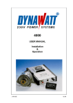
5000
USER MANUAL
Installation
&
Operation
02.08
1
Congratulations
on your purchase of a DYNAWATT 230V POWER SYSTEM 5000. You have now
acquired a high quality, precision-manufactured power supply system for mobile use.
Please read these Operating Instructions through carefully before using the system
for the first time.
In any event, installation should only be carried out by a qualified technical workshop.
Manufacturer:
DYNAWATT AG
Zinkereistrasse 35
8633 Wolfhausen
Switzerland
Tel: +41-55-253 26 00
Fax: +41-55-253 26 09
www.dynawatt .ch
2
SYSTEM DATA
The DYNAWATT 230V Power System consists of three parts. They are:
1. Generator
2. Control unit
3. Remote control
Figure 1
Figure 2
Figure 3
Page: 19
Page: 20
Page: 21 (option)
The basic system also comes with 2x installation brackets, 6m of generator cable.
Please note the following information on your system.
Generator:
Series No. ........................
Control unit:
Series No. ........................
SAFETY PRECAUTIONS
• The DYNAWATT Power System 5000 generates an output voltage of 230V AC.
When operating the system please therefore observe the general safety regulations
for using electrical equipment. In other words e.g. do not allow any liquids to get into
the housing, do not use any sharp instruments, in particular do not insert any
metallic objects into the ventilation slot!
• The system is electrically insulated (galvanic separation between electronics and
housing) and is not earthed to the chassis. (IT mains installation with potential
compensation)
• When the engine is running the circuits are live. In order to ensure optimum cooling
the unit must be installed vertically and the ventilation slots kept clear.
• All installation screws (installation kit) must be secured to prevent accidental
loosening by using Loctite.
IMPORTANT
Installation and maintenance of the system should only be carried out by trained
personnel. Any faults which are attributable to the use of components other than the
components supplied by DYNAWATT AG, or the failure to observe the safety
instructions as specified above, are not covered by the warranty.
A Power Transfer Switch must be installed if the vehicle (boat etc.) can also be
connected to other power sources e.g. 230V external power (shore power), generator,
inverter etc. Failure to comply with this instruction will cause damage to the control unit,
this damage is not covered by the guarantee. Power Transfer Switches are available
from DYNAWATT as an option.
3
INDEX OF CONTENTS
SAEFTY PRECAUTIONS
3
INDEX OF CONTENTS
2
TECHNICAL SPECIFICATION
7
CONTROL UNIT
GENERATOR
7
7
ADDITIONAL COMPONENTS
8
REMOTE CONTROL
POWER TRANFER SWITCH
8
8
LIST OF PARTS SUPPLIED
8
PARTS REQUIRED, NOT SUPPLIED
8
GENERATOR SPEED AND AVAILABLE POWER
9
GENERATOR SPEED
AVAILABLE OUTPUT IN WATTS
9
9
INTRODUCTION
10
MANUAL CONTENT
10
SYSTEM DESCRIPTION
10
GENERATOR AND CONTROL UNIT
REMOTE CONTROL
POWER TRANSFER SWITCH
10
10
10
OPERATION
11
ENGINE SPEED
OVERLOAD
START PHASE
REMOTE CONTROL (OPTION)
OFF
ON
INCREASE SPEED
OVERLOAD
UNDERVOLTAGE
SHORT CIRCUIT
SYSTEM ON AND OFF
11
11
11
12
12
12
12
12
12
13
13
PERIODIC MAINTENANCE
13
GENERATOR DRIVE BELT
GENERATOR BEARINGS AND BRUSHES
13
13
4
Installation Guidelines and Safety Precautions
14
GENERATOR
14
INSTALLATIONS SITE
CHOICE OF BELT PULLEY
CHOICE OF BELT
BELT PULLEY ALIGNMENT
14
14
15
15
INSTALLATION
16
GENERATOR INSTALLATION
FITTING THE GENERATOR COVER
GENERATOR MAGNETIZATION
CONTROLLING RPM OF VEHICLES ENGINES
CONTROL UNIT MOUNTING
CONNECTION THE GENERATOR CABLE
230 V CONNECTION
16
16
16
16
17
17
17
STARTING THE SYSTEM
18
TROUBLESHOOTING
18
TESTING THE GENERATOR
18
WARRANTY TERMS
19
LIST OF FIGURES
20 - 29
5
List of Figures
All figures can be found at the back of the manual, listed in the order of the figure
numbers.
Figure
Page
Description
1
17
Generator
2
18
Control Unit
3
19
Remote Control
4
20
Generator Performance Curve
5
21
Preparing the Connection Cable
6
22
Generator and 230V Connection Terminals
7
23
Power Transfer Switch
8
24
Control Unit Installation
9
25
Generator Installation
10
26
System Block Diagramm
6
Technical Specification
CONTROL UNIT
Output voltage:
Phases:
Transformation:
Frequency:
Output wave:
Output power:
Start-up current:
Efficiency:
Weight:
Protection category:
System Protection:
Dimensions:
No Load:
230 - 232 V AC
Load:
235 - 237 V AC
1 phase
250V by the generator to 230V
50 Hz ± 0.5%
sine wave
5000 VA intermittent @ 6000rpm generator
4800 VA continuous (25° C temp.)
70 Amp (5ms)
96%
9 kg
IP 21
System automatically shuts of by: overheating
or short circuit (double fault)
See Figure 1
GENERATOR
Power output:
Output voltage:
Output frequency:
Generator speed:
Weight:
Belt pulley:
Efficiency:
Insulation category:
Phase resistance:
Resistance rotor:
Dimensions:
Cable:
max. 5300 Watt (25° C temp.)
3 x 250V AC
variable, between 300 and 1500 Hz
15,000 rpm intermittent
13,000 rpm continuous
7.5 kg
DIA 60mm, 2 x 9,5mm belt
60%
H (170°)
2.8 Ohm ± 0.3 (from phase to phase)
2.5 to 3.5 Ohm
See Figure 2
5 X 2.5mm2, 10m (max. 20m on request)
REMOTE CONTROL
Switch:
Indicators
Connection cable length:
Dimensions:
STANDBY / ON
add rpm, overload, overheating, short circuit
7.5m available, (max. 20m on request.
See Figure 3
7
Additional components
Power Transfer Switch
A Power Transfer Switch must be installed for switching over from an external power
source (e.g. shore power 230V) to on board power source, DYNAWATT. Fig. 7.
List of Parts Supplied
1. Generator is supplied with 10m, 5 x 2.5mm2 cable
2. Control unit
a. 2 pc. attachment brackets (loose)
b. 4 pc. M6 x 10mm attachment screws for brackets (on the back of Control Unit)
c. EMI fitting for the generator cable (on the front side of CU)
d. Fitting for the 230V cable (on the front side of CU)
3. Remote control with 7.5m cable (available as an option)
4. User manual
Parts Required, Not Supplied
1.
2.
3.
Three-conductor Output power cable, min. 3x2.5mm2
Vehicle-specific installation sets available on request.
4 pc. attachment screws for the Control Unit
Generator Speed and Available Power
Calculation Sheet
(Note: Measure the belt pulley external diameter)
Generator speed
Belt pulley dia. generator side:
Belt pulley dia. motor side:
Motor speed idling:
Motor speed max.:
Belt pulley transmission:
Generator idling rpm:
Generator max. rpm:
Ra = .......... mm
Rm = ......... mm
nL = ........... rpm
nM = .......... rpm
iR = Rm : Ra= .............
NAIdling = (iR) x (nL) = ........ rpm
Namax = (iR) x (nM) = ........ rpm
Available output in watts
Read from the Curve of Figure 21
Power at engine idle speed (NAIdling)
Minimum speed for full load
.................. Watt
.................. rpm
8
Introduction
MANUAL CONTENT
This manual covers: Operating Instructions, Installation Guidelines and Installation
Instructions.
SYSTEM DESCRIPTION
Generator and Control Unit
The system consists of a high performance generator which is belt-driven by the main
engine and controlled by the control unit. Whenever the engine is running, a precisely
controlled 230V power source with 50 Hz sine wave AC is available, just turn the ON/OFF
switch to ON.
Remote Control
The remote control provides a POWER ON and STANDBY OFF switch and has 4 LED
status and fault indicators.
Power Transfer Switch
A Power Transfer Switch is required for switching between an external power source
(230V mains) and the DYNAWATT Power System.
WARNING
Voltage must never be connected to the control unit! Return voltage will
immediately result in the control unit being damaged!!
NO WARRANTY
9
OPERATION
Figure 4. At full power the system delivers 5000 Watts AC and can deliver higher peak out
put on a temporary basis. However, the system automatically limits the output power in
case of overload. Overload causes the output voltage to drop, this can have a negative
affect on the applied loads. This chapter explains how the user can avoid this situation
arising. It deals with four areas.
1. Motor speed
2. Overload
3. Start phase
4. Remote control
Engine speed
At idling speed the generator delivers a percentage of its potential output. Generation of
the maximum output requires a higher engine speed. Figure 4 shows a performance curve
for calculating the drive ratio, the output available from the system on idling speed and the
minimum engine speed required in order to achieve the system’s maximum output.
Overload
With most overload situations there are three adjustment options.
1. Reduce the electrical load
2. Increase the motor speed slightly
3. Shut off the entire power consumption temporarily by switching off the control unit
or switching to STANDBY on the remote control. The load must then be reduced
or the motor speed first increased.
Start phase
Electrical consumers (in particular electric motors) take up far more current when they are
switched on than when in operation. Electric motors are amongst the biggest ‘consumers
of electricity, e.g. an air conditioning system which requires 6 - 7 amps when running can
require a starting current of up to 50 amps. The DYNAWATT 5000 delivers up to 70 amps
starting current. In some situations the user will have to follow the start-up procedure as
explaned below:
1.
2.
3.
Switch off all loads
Switch on the largest load first
Switch on the remaining small loads.
If the starting current for a load is too high then a soft start can be connected between the
DYNAWATT and the user. The soft start reduces the starting current by up to 70% by
electronically slowing down the start-up speed of the load. This enables motors with
considerably higher starting currents to be operated.
Remote control (option)
10
STANDBY
The system is switched to ‘STANDBY’ by pressing the toggle switch. In this state there is
no voltage on the Output and the ‘STANDBY’ LED light comes on.
POWER ON
Pressing the toggle switch to ‘POWER ON’ activates the system. The ‘ON’ LED light
comes on if the system is switched on.
NOTE
The control unit mains switch must be set to ON if the remote control is used.
Otherwise it will not function.
INCREASE SPEED
The control unit continuously measures the power output. If the voltage falls by more than
5% under load or because the generator speed is too slow, with the result that the power
output is no longer sufficient for the current level of consumption, then the control unit
increases the magnetising voltage. Once this reaches the maximum of 14V and the
voltage generated is still below 220V then the ‘ADD RPM’ LED light comes on.
Remedy:
- Increase engine speed
- Check belt tension for slippage, tighten or replace belt
OVERLOAD
Under a overload the current limiter limits the output current to 22.5 amps, the
‘OVERLOAD’ LED will come on, Output Voltage will drop depending on the overload. The
system can however still be operated without any problem. CAUSON have to be taken in
order not to affect loads applied. Some appliances may be damaged by undervoltage!
If there is a sudden heavy load increase the system automatically shuts off and the
‘SHORT CIRCUIT’ LED light comes on.
Remedy:
Reduce the load, switch the system ON.
HIGH TEMPERATURE
Overheating
A continuously high load or an overload can cause the system to overheat. If the system
reaches a temperature of 65°C the ‘HIGH TEMPERATURE’ LED light starts to flash. At
68°C the system automatically shuts off. The system only switches back on automatically
once it has cooled down to 52°C.
The cause of the overheating can be either incorrect installation, inadequate cooling or a
defective fan.
Remedy:
Check that the Control unit is well ventilated. Test the fan operation, if a
suction filter is used the filter may need to be cleaned.
11
SHORT CIRCUIT
In the event of a short circuit or a very high load (>70 amps) the control unit automatically
switches off and the ‘SHORT CIRCUIT’ LED light comes on.
Remedy:
Switch off the unit, reduce load or correct the fault. Then switch the unit back
ON again. The system does not switch back on automatically after a short
circuit.
System ON and OFF
If the system has been turned off by engine shut down the ON / OFF switch must be rest
to off and on again, otherwise the system will not start.
Periodic Maintenance
Generator Drive Belt
The system does not need any periodic maintenance with the exception of checking the
belts which are used to drive the generator. We strongly recommend purchasing
replacement belts. Where a twin belt system is used both belts must be replaced
simultaneously. Only high performance belts should be used, such as e.g. GATES
Type ESC or CONTI Industry.
NOTE
A new V-belt will expand during the first hours of operation and the tension must
therefore be subsequently adjusted after the first 10 hours.
Generator Bearings and Brushes
Depending upon the load and the extent to which the system is used the brushes and
bearings should be replaced after approx. 1000 hrs or 80,000 km. Please contact your
nearest DYNAWATT dealer for replacements.
12
Installation Guidelines and Safety Precautions
IMPORTANT
It is essential for the system to be installed professionally to ensure reliable operation over
a long period of time. The mechanical installation of the generator is of particular
importance. In the event of any problems occurring please contact your DYNAWATT
dealer.
GENERATOR
A number of factors must be taken into account to ensure the generator is correctly
installed. Particular attention must be paid to the correct selection criteria.
1.
Installation site and stability
2.
Choice of belt pulley for the right speed range
3.
Choice of belt for minimum system maintenance
4.
Belt positioning, alignment and tension.
Installation Site
The generator can:
1.
2.
3.
be fitted to the engine block as an addition to the existing alternator
be fitted next to the engine. This requires a special, automatic belt tensioner which
is available as an accessory.
Whichever choice you make it is essential for the generator to be installed securely.
INFORMATION
The generator cable should be laid in a separate protective conduit to safeguard it from
mechanical effects.
Choice of Belt Pulley
See Figure 4; System Performance curve. The curve shows that no output is delivered by
the system until the generator speed reaches approx. 2900 rpm. and the system
generates a 50% output at a generator speed of approx. 3700 rpm.
To achieve the best results the system should reach a minimum generator speed of 3500
rpm at engine idle
Generator maximum speed:
13,000 rpm continuous
15,000 rpm maximum
13
Choice of Belt
The power which is transferred via the belts depends upon the belt width, wrap-around
angle, the number of belts and the belt tension. The service life of a single belt system is
considerably less than that of a twin belt system.
DIA pulley
Belt size
Type
Qty
65 mm
60 mm
65 mm
50 mm
12.5mm
9.5mm
12.5
Micro-V
12.5 ESC toothed
9.5 ESC toothed
12.5 ESC toothed
Micro-V 6 grooved
1
2
2
1
Max. output
5000 Watt
5000 Watt STANDARD
>5000 Watt
5000 Watt
Belt Pulley Alignment
Nothing is more important for the service life of a belt than the alignment of the generator
pulley and engine pulley. Both pulleys must be absolutely parallel and flush aligned. If a
pulley is positioned at an angle to or slightly behind the other this can lead at least to a
material related reduction in the useful life of the belt. In addition the belt may slip out of
the grooves.
INSTALLATION
Generator Installation
Figure 9. The generator is fitted as an additional alternator. It must be securely and
permanently installed since the drive takes two to three times more power than factoryfitted standard alternator. The ratio to be taken into account during installation is
dependent upon the engine idling speed and the maximum speed.
NOTE
All installation screws must therefore be secured using Loctite to prevent
accidentally working loose.
Fitting the generator cover
The generator cover must be positioned in such a way that the generator is able to take in
dry, cool air via the intake opening (DIA. 55 mm). If this is not possible then a suction
hose must be connected to the opening to provide dry, cool air and must be fitted in an
appropriate position in the vehicle. The higher the air intake temperature the greater the
heat related loss of generator performance. See Figure 9.
14
Generator Magnetization
The generator must be magnetized before installing it otherwise the system may not
operate at all.
Attach the generator cable, No. 4 to (+) plus and No.5 to (-) minus to a 12 volt battery for
approx. 5 seconds. Note: Some generator cables has Yellow/Green as No.5.
WARNING
On no account must this be carried out whilst the engine is running and the Control
Unit connected. The Control Unit will be immediately damaged by high voltage. NO
WARRANTY
Engine rpm control
To enable the idling speed to be increased we recommend fitting a hand throttle or an
automatic engine speed accelerator. Available as an option.
Control Unit mounting
The control unit is to be installed in a well ventilated, dry place with average temperature
levels. See Figure 8. The ideal position is against a wall, cable connections at the bottom.
For this the two brackets, supplied separately, are screw connected to the rear of the
control unit. The control unit must not be installed horizontally, it is important to ensure
that the air outlet slots on the reverse are not blocked.
WARNING
The brackets must only be fitted to the rear of the Control Unit by using the supplied M6
screws, with a maximum length of 10 mm.
Connection the generator cable
The five conductor generator cable has to be prepared as shown in Figure 5. Open the
front cover of the control unit (undo 3 screws) and insert the cable into the housing through
the metal fitting. Lead the numbered cables (1-5) to the correct terminal number and
attach. To attach the cable press the terminal clamp down by using a small screwdriver.
Ensure the cables are securely clamped. The cable shield mash is fitted as shown in
Figure 5. Then gently tighten the screw connection using an SW 30 mm spanner. Make
sure that the gen.cable is not turning around while tightening.
Cable function:
No.
1
2
3
4
5
Function
1st Phase
2nd Phase
3rd Phase
(+) Magnetizing current
(-) Magnetizing current
15
Terminal No.
L (1)
L (2)
L (3)
+ (4) red
- (5) blue
Voltage
250V AC
250V AC
250V AC
+12V DC
- 12V DC
230V Connection
Prepare cable as shown in Figure 5 and pull it through the plastic screw connection into
the Control Unit. Attach cable to the output filter terminal clamp. Ensure secure fit.
Minimum recommended cable size: 3 x 2.5mm2. (Cable up to 4mm2 possible)
230V connection
terminal function:
Terminal No.
Function
Cable colour
L
N
E
Phase
Neutral
Earth
Brown
Blue
Yellow/Green
Starting the System
The following must be checked before starting the system:
- that the generator cable has been correctly installed
- that the V-belt tension has been correctly set
- that all installation screws have been tightened
- that the cables have been connected to the correct terminals and are securely
clamped.
- when unit is switched ON, check if fan is operating
Troubleshooting
The system doesn’t work
Check the condition and tension of the V-belts. Check
the cable and terminal connections.
LEDs on the remote control faint
but no power
Check to see whether cable 4 (+) and 5 (-)
have been connected the wrong way around or whether
generator must be
magnetized again . See Page 14.
Increase Speed Light comes on
V-belt slipping, check tension and condition, adjust
tension.
16
Testing the Generator
With generator turning:
250V AC must be measured on the terminal from phase to
phase (1-2-3). (Warning, high voltage)
With generator stationary: The resistance on the terminal from phase to phase (1-2-3)
must be 2.8 ohms +/- 0.3.
If fault displayed:
Contact supplier
Rotor resistance:
2.5 to 3.5 ohms between cable no. 4 (+) and 5 (-)
If fault displayed:
- Check generator carbon brushes
- Clean collector ring with fine sandpaper if necessary
Warranty Terms
1.
The system is guaranteed for material and production defects. The warranty only
covers the unit itself and not any consequential damage. The warranty application
form, containing adequate information, must be sent to the vendor.
2.
The warranty period extends for 12 months from the date of purchase by the first
purchaser.
3.
The system must be used and installed in accordance with the details contained in
these Operating Instructions.
4.
The warranty does not cover:
- faults and repair costs caused as a result of improper use, modifications or
incorrect installation
- injuries and indirect damage to vehicles etc.
- consequential costs and costs incurred due to loss of vehicle
- moving parts such as V-belts, LED’s, plastic components etc.
5.
The warranty application must be submitted within a reasonable period of time, if
possible within 14 days following the occurrence of the damage. The applicant must
provide appropriate evidence to show when and where the system was purchased.
6.
Despatch costs, installation and dismantling costs are to be borne by the applicant
unless expressly agreed otherwise.
17
Figure 1 Generator
18
Figure 2 Control unit
19
P 30118
P 30115
P 30115-70
Adapter
RJ45-SUB D9
Remote control
RJ45 connector
Cable RJ45 7m
Figure 3 Remote Control
20
Figure 4
Generator Performance Curve
21
Figure 5
Preparing cables
22
Figure 6
Connecting Terminals
23
Figure 7
Power Transfer Switch
24
Figure 8
Control Unit Installation
25
Generator Installation with 2x9,5mm V-Belts
Generator with DIA 55mm air intake hose
Cut any place at the rear cover for gen.cable exit
26
Figure 10
System Block Diagramm
27