1
COPAS™ BIOSORT INSTRUMENT
Automated Analysis, Sorting, and Dispensing of small model organisms, beads, and particles
SERVICE MANUAL
Rev. 1.00
Last Updated On: May 8, 2003
Table of Contents
TABLE OF CONTENTS ................................................................................................................... 2
INTRODUCTION ............................................................................................................................ 3
WARRANTY ................................................................................................................................. 3
WARNINGS AND PRECAUTIONS .................................................................................................... 4
SHIPPING CHECKLIST FORM ......................................................................................................... 5
For Customers located in North America, Japan....................................................................................................5
For Customers located in Europe (except United Kingdom)..................................................................................6
For Customers located in United Kingdom ............................................................................................................7
REAGENTS USED .......................................................................................................................... 8
Sheath Reagent .......................................................................................................................................................8
Control Particles .....................................................................................................................................................8
Cleaning Reagent ...................................................................................................................................................8
Bleach
...............................................................................................................................................................8
Sterilization Solution ..............................................................................................................................................8
MATERIALS REQUIRED FOR SERVICE (NOT PROVIDED) ............................................................... 9
WORK AREA AND FACILITIES SPECIFICATIONS ............................................................................ 9
Work Area Requirements .......................................................................................................................................9
Environmental Requirements .................................................................................................................................9
Air Requirements ...................................................................................................................................................9
Electrical Requirements........................................................................................................................................10
UNPACKING THE COPAS INSTRUMENT ..................................................................................... 11
OPTICAL FIBER INSPECTION, INSTALLATION AND CLEANING .................................................... 11
Procedure .............................................................................................................................................................11
FINAL SET-UP / ADJUSTMENT PROCEDURES .............................................................................. 13
Set Up
.............................................................................................................................................................13
Software Verification ...........................................................................................................................................14
Fluidics Check......................................................................................................................................................15
Laser Power Adjustment ......................................................................................................................................16
Waste Tray Alignment .........................................................................................................................................17
PMT Set up...........................................................................................................................................................18
COPAS INSTRUMENT TEST ....................................................................................................... 19
Instrument Set-Up ................................................................................................................................................19
Performance Set-Up .............................................................................................................................................20
Performance Verification .....................................................................................................................................22
Sorter Operation Verification ...............................................................................................................................24
Instrument Preparation .........................................................................................................................................25
Instrument Test Worksheets .................................................................................................................................26
DAILY / SHORT TERM COPAS INSTRUMENT MAINTENANCE .................................................... 27
Daily Maintenance Procedure ..............................................................................................................................27
Visual Tubing Check............................................................................................................................................28
ANNUAL PREVENTATIVE MAINTENANCE PROCEDURE ............................................................... 29
SYSTEM INTERCONNECT DRAWINGS .......................................................................................... 31
GENERAL PARTS LIST ................................................................................................................ 32
PRINTED CIRCUIT BOARDS ........................................................................................................ 33
MAJOR CABLE ASSEMBLIES....................................................................................................... 33
CONTACT INFORMATION ............................................................................................................ 34
NOTES ........................................................................................................................................ 34
Union Biometrica, Inc. Confidential
www.unionbio.com
2
Introduction
The COPAS BIOSORT automates the analysis, sorting, and dispensing of objects ranging from 40 - 125
microns including particles, beads, seeds, and small model organisms. Using the physical parameters of
object length, optical density, and the intensity of fluorescent markers, objects are sorted according to user
selectable criteria, and then may be dispensed into stationary bulk receptacles or multi-well microtiter
plates.
This COPAS BIOSORT Service Manual details those procedures pertinent to the maintenance of the
COPAS instrument and all top level assemblies that are used in the manufacture of the instrument.
Requests for more detailed lower level parts and materials will be addressed by Union Biometrica, Inc. on
an individual basis.
Warranty
The Union Biometrica COPAS instrument is warranted to be free from defects in material and
workmanship for a period of one (1) year from the date of installation and acceptance. Union Biometrica
or authorized personnel will repair, at our election, by replacement, any part of the instrument, which fails
within the warranty period. As a part of this warranty period, the customer will receive unlimited
telephone assistance support Monday through Friday, during normal working hours from 9:00 AM-5:00
PM Eastern Standard Time, up to four (4) emergency on-site visits per year, all replacement parts, labor,
and travel, and one (1) preventive maintenance visit per year. This warranty is extended to the original
buyer purchasing the equipment from Union Biometrica or authorized distributor.
This warranty does not include routine cleaning, adjustment or normal wear and tear from use unless
designated by buyer as its annual preventative maintenance visit and excludes: (A) Service or parts
required due to damage caused by accident, neglect, breakage, misuse, alteration to the equipment,
electrical current fluctuations, unfavorable environmental conditions, work performed by an unauthorized
agent, or forces of nature; (B) work which, in the sole exclusive opinion of Union Biometrica, is
impractical to perform because of the platform’s location or proximity to any other device; (C)
modifications to the instrument for performance outside of the published performance specifications; (D)
Service required to parts in the system that have been exposed to or otherwise affected by solutions or
reagents not manufactured by Union Biometrica , or another authorized manufacturer, which causes poor
or erratic performance and / or shortened component life; (E) Service performed by an unauthorized third
party; or (F) instrument refurbishing for cosmetic purposes. All parts replaced under the original
warranty will be warranted only until the end of the original instrument warranty. Union Biometrica must
receive all requests for warranty replacement or authorized distributor within thirty (30) days after the
component failure.
It is the owner's responsibility to maintain the instrument in accordance to Union Biometrica's guidelines.
Union Biometrica reserves the right to change, alter, modify or improve any of its instruments without
obligation to make corresponding changes to any instrument previously sold OR shipped. All service will
be rendered during Union Biometrica's normal hours of operation. Repairs requested outside of normal
business hours will be performed at Union Biometrica's discretion, at prevailing after hour rates. Such
requests must be accompanied by an approved purchase order.
Union Biometrica, Inc. Confidential
www.unionbio.com
3
The following exceptions apply:
1. Consumable items, including reagents and solutions, pump tubing, tubing, are warranted to be
free of defects at the time of installation. Union Biometrica does not warrant parts and accessories
not manufactured by or for Union Biometrica. Union Biometrica will assist buyer in obtaining
any information or service from any manufacturer for any part not covered by Union Biometrica.
2. Freight charges are at the customers’ expense.
The warranty is invalid if:
1. The COPAS platform is used for purposes outside the scope of supported applications and
specifications.
2. System modifications, not approved by Union Biometrica in writing, are performed.
Warnings and Precautions
The COPAS BIOSORT is a Class I laser product containing a Class IIIA laser. The COPAS Argon
Laser System contains a Class III B laser, which is fiber coupled through a fiber optic. Only
qualified service personnel should remove the COPAS Argon Laser System or the optics assembly
covers.
The COPAS BIOSORT is comprised of the Dispenser and the Argon Laser System. This term is used in
reference to the combination of these two components. Use of the COPAS BIOSORT Dispenser and
Argon Laser System in a manner not specified by Union Biometrica may impair the protection provided
by the equipment.
The COPAS instrument will be factory shipped to you in protective packaging and will be installed by a
trained Union Biometrica, Inc. representative. The Union Biometrica service representative will also
verify the system performance. If the instrument must be moved or maintenance must be performed,
Union Biometrica, Inc. recommends that a trained Union Biometrica representative install the system and
perform most maintenance functions. The connection of the Laser fiber optic cable requires special
attention and should not be attempted by untrained persons.
In order to prevent the system from overheating, ensure that the installation permits the unrestricted flow
of air around the system components and confirm prior to installation that the Work Area and Facilities
specifications have been met.
The COPAS BIOSORT should be used only by trained laboratory personnel. Use of this instrument by
an untrained operator could result in damage to the product or injury to the operator.
Other than procedures outlined in the Operator’s Manual, there are no other operator required electrical,
optical, or mechanical adjustment or serviceable components.
Please refer to the Operator’s Manual for complete Safety Warnings and Precautions.
Union Biometrica, Inc. Confidential
www.unionbio.com
4
Shipping Checklist Form
For Customers located in North America, Japan
COPAS BIOSORT
Part Number:
Quantity
1
1
1
1
1
1
2
20 ft.
1
1
1
1
1
2
1
1
1
1
1
1
1
350-5000-000
Serial Number:_______________________
Description
Power Cord Cable
Power Strip
RS-232 Data Cable
CSM Cable - ReFLX ONLY
Laser Power Cord
Strait Blade Laser Plug
Tubing Clamp
PVC Air Tubing
Threaded/Barbed Air Fitting
Slotted Screwdriver
Waste Bottle
Vent Tubing
Waste Pump Tubing
GP Sheath Reagent and MSDS
Cleaning Reagent and MSDS
Installation Disc
Laser System Cable
GP Control Particles and MSDS
Bubble Trap Filter (only with ReFLx)
Reference Manual
Information Packet
Part Number
066-0004-000
066-0007-500
066-0009-010
066-0009-020
067-0020-004
067-0030-001
100-0010-001
111-0250-002
119-0003-000
145-0020-000
300-5044-000
300-5062-000
300-5068-000
300-5070-000
300-5072-000
300-5080-____
310-5018-000
310-5071-000
340-5014-000
350-5074-000
Packaged by: ___________________ Date: ______Inspected by: ________________Date: ______
Union Biometrica, Inc. Confidential
www.unionbio.com
5
For Customers located in Europe (except United Kingdom)
COPAS BIOSORT
Part Number:
Quantity
1
4
1
1
1
1
1
2
20 ft.
1
1
1
1
1
2
1
1
1
1
1
1
1
350-5000-000
Serial Number:_______________________
Description
Power Strip
Jumper Cables
Power Strip/Wall Cable
Laser/Wall Cable
Compressor/Wall Cable
RS-232 Data Cable
CAM Cable - ReFLX ONLY
Tubing Clamp
PVC Air Tubing
Threaded/Barbed Air Fitting
Slotted Screwdriver
Waste Bottle
Vent Tubing
Waste Pump Tubing
GP Sheath Reagent and MSDS
Cleaning Reagent and MSDS
Installation Disc
Laser System Cable
GP Control Particles and MSDS
Bubble Trap Filter (only with ReFLx)
Reference Manual
Information Packet
Part Number
066-0007-000
066-0007-100
066-0007-200
066-0007-300
066-0007-400
066-0009-010
066-0009-020
1 0 0 -0 0 1 0 -0 0 1
111-0250-002
119-0003-000
145-0020-000
300-5044-000
300-5062-000
300-5068-000
300-5070-000
300-5072-000
300-5080-____
310-5018-000
310-5071-000
340-5014-000
350-5074-000
Packaged by: ___________________ Date: ______Inspected by: ________________Date: ______
Union Biometrica, Inc. Confidential
www.unionbio.com
6
For Customers located in United Kingdom
COPAS BIOSORT
Part Number:
Quantity
1
4
1
1
1
1
1
2
20 ft.
1
1
1
1
1
2
1
1
1
1
10
1
1
350-5000-000
Serial Number:_______________________
Description
Power Strip
Jumper Cables
Power Strip/Laser/Wall Cable
Laser/Compressor/Wall Cable
RS-232 Data Cable
CSM Cable - ReFLX ONLY
Laser Power Cord
Tubing Clamp
PVC Air Tubing
Threaded/Barbed Air Fitting
Slotted Screwdriver
Waste Bottle
Vent Tubing
Waste Pump Tubing
GP Sheath Reagent and MSDS
Cleaning Reagent and MSDS
Installation Disc
Laser System Cable
GP Control Particles and MSDS
Bubble Trap Filter (only with ReFLx)
Reference Manual
Information Packet
Part Number
066-0007-000
066-0007-100
066-0007-310
066-0007-410
066-0009-010
066-0009-020
067-0020-003
1 0 0 -0 0 1 0 -0 0 1
111-0250-002
119-0003-000
145-0020-000
300-5044-000
300-5062-000
300-5068-000
300-5070-000
300-5072-000
300-5080-____
310-5018-000
310-5071-000
340-6000-000
350-5074-000
Packaged by: ___________________ Date: ______Inspected by: ________________Date: ______
Union Biometrica, Inc. Confidential
www.unionbio.com
7
Reagents Used
Do not use unapproved solutions in the COPAS BIOSORT. The use of unapproved solutions can cause
damage to the device and will void the warranty. The specialized reagents discussed below are available
from Union Biometrica, Inc. Material Safety Data Sheets are enclosed in every shipment of Union
Biometrica, Inc. supplied reagents and are also available upon request.
NOTE: Performance Specifications are only valid with Union Biometrica, Inc. reagents.
Sheath Reagent
Sheath reagent is an aqueous based reagent containing surfactant. The sheath reagent must be
compatible with the control particles used and the sample to be analyzed. For most applications,
COPAS GP Sheath, PN 300-5070-000 is recommended.
Two 20 Liter containers of PN 300-5070-000 are shipped with each COPAS BIOSORT instrument.
Control Particles
Control particles are latex beads that are uniform in size, suspended in a reagent compatible with the
sheath reagent and sample to be analyzed. For most applications, GP 42 micron HF Control Particles,
PN 310-5071-000 are recommended.
One 1 Liter container of PN 310-5071-000 is shipped with each COPAS BIOSORT instrument.
Cleaning Reagent
Cleaning reagent is an aqueous based reagent containing surfactant specially formulated for use with
all COPAS platforms. This solution should be used for daily cleaning procedures Cleaning reagent
should be used for daily maintenance.
One 1 Liter container of PN 300-5072-000 is shipped with each COPAS BIOSORT instrument.
Bleach
Bleach is used on the COPAS instrument for troubleshooting procedures including breaking up
proteins potentially causing a blockage in the flow cell or fluidics. Bleach is also used to clean the
internal flow cell. The manufacturer does not supply ethanol.
NOTE: DO NOT use on external surfaces of optical components
UNION BIOMETRICA, INC. recommends that Clorox® brand bleach be used due to its observed
low particulate count. If a different brand of bleach is used, filtering is required.
When using bleach, use 5% sodium/calcium hypochlorite at a 50% dilution.
Sterilization Solution
70% Ethanol is used on the COPAS instrument for sterilization procedures and in certain
troubleshooting procedures. The manufacturer does not supply ethanol.
Union Biometrica, Inc. Confidential
www.unionbio.com
8
Materials Required for Service (Not Provided)
•
•
•
•
•
•
•
Screwdrivers: 10”+ length and jewelers size
Oscilloscope & PMT wires
Needle nose pliers
Paper towels
Cable ties to secure tubing and cables
50 mL syringes for removing liquid from the sample cup
96 well plates and lids
•
Argon Laser Alignment Glasses [2-3@488-515nm, amber lens, 70% VLT] – Only required if
service will be performed on the Argon Laser by the customer. Union Biometrica highly
recommends that any laser service be performed by a Union Biometrica trained service person.
Work Area and Facilities Specifications
Prior to installation of the COPAS BIOSORT instrument, confirm that the work area and facilities
comply with the below specifications.
Work Area Requirements
•
•
•
The COPAS system requires a permanent, open, level, vibration free, working space with the
dimensions of 3 feet (1 meter) deep x 7 feet (2.3 meters) wide x 4.75 feet (1.4 meters) high. No
other equipment should be placed over the COPAS system. There also should be user access on
both sides of the working area.
A COPAS system with the optional Zymark Twister® Robot will need an additional space to the
left of the COPAS of 3 feet (1 meter) deep x 2 feet (0.6 meters) wide x 2 feet (0.6 meters) high.
The Union Biometrica supplied optional Air Compressor requires approximately 14 inches (36
centimeters) deep x 18 inches (46 centimeters) wide x 20 inches (51 centimeters) high of stable
floor space.
Environmental Requirements
•
•
•
•
This instrument is designed for use at an altitude of up to 2000 meters, in an ambient operating
temperature between 15° and 30°C (60° to 85°F) with a relative humidity of 0% to 85% noncondensing, decreasingly linearly to 50% relative humidity at 40°C (104°F). Temperature should
not fluctuate more than +/- 1.5 °C from the time of experimental setup through completion or
adjustments will need to be made.
Ensure that adequate ventilation of the system components is provided. It is important that
ventilation openings not be blocked while the system is powered ON.
The system generates approximately 3800 BTU/Hr.
This instrument is rated, per IEC 60529, for installation in an IP00 environment. It is intended
that it be installed in a laboratory environment protected from dust and spray.
Air Requirements
•
The input air pressure should be at least 50 psi but no more than 100 psi of filtered, at 2 CFM, of
non-condensing, water and oil free air. The optional COPAS Air Compressor is available for
laboratories that cannot meet these requirements.
Union Biometrica, Inc. Confidential
www.unionbio.com
9
Electrical Requirements
•
•
•
•
•
Place the COPAS system and components within 6 feet (2 meters) to the power outlets.
COPAS systems and the Laser should each be connected to separate, dedicated electrical supply
circuits, using the supplied detachable line cords (or CE7/VII approved equivalent detachable
cords for Europe). The supply circuits must be compliant with local electrical codes, and must
include a dedicated protective ground connection to protect the system. The main supply voltage
is not to exceed 10% of the nominal voltage.
Place the instrument so that the detachable line cords remain readily accessible. This is essential
to permit use of the line cords as the emergency disconnection devices in case of a fault.
Circuit Requirements for 120 VAC Countries:
o COPAS Instrument, PC & monitor – 100-120VAC, 15 Amp, 50/60 HZ, single phase on a
dedicated line with protective earth ground.
o Argon Laser System – 100-120VAC, 20 Amp, 50/60 HZ, single phase on a dedicated line
with a protective earth ground.
o Air Compressor (optional) – 100-120VAC, 13 Amp, 50/60 HZ, single phase on a
dedicated line with protective earth ground. (May be placed on instrument line if
necessary if surge protection is provided for the instrument, PC, and monitor.)
Circuit Requirements for 230 VAC Countries:
o COPAS Instrument, PC & monitor – 220/240VAC, 10 Amp, 50/60 HZ, on separate
dedicated lines with protective earth ground.
o Laser – 220/240VAC, 16 Amp, 50/60 HZ, on separate dedicated lines with protective
earth ground.
o Air Compressor (optional) – 220/240VAC, 10 Amp, 50/60 HZ, single phase on a
dedicated line with protective earth ground. (May be placed on instrument line if
necessary if surge protection is provided for the instrument, PC, and monitor.)
Union Biometrica, Inc. Confidential
www.unionbio.com
10
Unpacking the COPAS Instrument
General recommended guidelines for unpacking a COPAS instrument and laser assembly.
1. Confirm work area and facilities meet specifications outlined by Union Biometrica in this Service
Manual.
2. Inspect all containers for damage. If there is any damage, contact Union Biometrica immediately
to report the damage.
3. Inventory all containers. It is recommended that, if storage area is available, customers keep the
COPAS instrument containers to be used for long term instrument storage, or moving the
instrument from one location to another.
4. Remove system components from containers and move to laboratory bench where the system will
be permanently located.
5. Due to the weight of the instrument [40 Kg (88 lbs)], a minimum of two people is required to
move the COPAS BIOSORT. In order to lift the unit safely without tipping, one person should
be located on either side of the instrument to lift the unit by placing one hand under the front and
one under the rear of the base.
6. Due to the weight of the external laser, [33.6 Kg (74 lbs)], a minimum of two people is also
required to move the unit. Lift the Argon Laser System by placing one hand under the front and
one under the rear of the base.
7. Connect all cables, tubing, and bottles according to COPAS BIOSORT System Interconnect
Drawing and COPAS BIOSORT Fluidic Diagram contained in this Service Manual.
Optical Fiber Inspection, Installation and Cleaning
According to UBI Operational Instruction: OI 112, Optical Fiber Inspection, Installation and Cleaning
Instructions, Revision No. 1, (Last revision date: 1/22/02)
Purpose: The purpose of this OI is to describe the pre-installation inspection procedure, the installation
procedure, the installation inspection procedure and the cleaning procedure of an Optical Fiber.
NOTE: Use proper laser safety precautions at all times while performing these steps. Always wear argon
safety glasses.
Procedure
1. Pre-Installation Inspection
a. Set the laser to STAND-BY mode.
b. Close laser shutter.
c. Remove the fiber from the instrument.
d. Position the fiber approximately 12” (30cm) from a diffuse white target.
e. Open the laser shutter.
f. Examine the beam pattern for a uniform circular beam.
Union Biometrica, Inc. Confidential
www.unionbio.com
11
g. If a uniform circular beam is observed, proceed to Installation, Step 2.2. If concentric rings,
multiple patterns or any other distortions are observed, go to Cleaning Procedure, Step 2.4
and then repeat Steps 2.1.1 through 2.1.6 one time.
h. If concentric rings, multiple patterns or any other distortions are still observed, the fiber is
damaged and a new fiber must be inspected.
2. Installation
a. Set the laser to STAND-BY mode.
b. Close laser shutter.
c. Soak a cotton swab with 100% Methanol.
d. Clean the fiber receptacle with the soaked cotton swab.
e. Insert the fiber into the receptacle in the optical assembly ensuring the fiber face does not
come in contact with the flat surface in between the threaded ring and the receptacle bore.
3. Installation Inspection
a. Open the laser shutter.
b. Place a beam-blocking device into the beam path between the spherical lens and the
cylindrical lens mount.
c. If a uniform circular beam is observed, installation is complete. If concentric rings, multiple
patterns or any other distortions are observed, go to Cleaning Procedure, Step 2.4 and then
repeat Steps 2.3.1 through 2.3.2 one time.
d. If concentric rings, multiple patterns or any other distortions are still observed, the fiber is
damaged and a new fiber must be installed.
4. Cleaning Procedure
a. Set the laser to STAND-BY mode.
b. Close laser shutter.
c. Soak a piece of lens tissues with 100% methanol.
d. Clean the fiber face with soaked lens tissue.
e. Dry the fiber face with a second piece of lens tissue.
f. Open the laser shutter.
g. Perform appropriate Inspection (pre-installation or installation).
h. If a uniform circular beam is observed, return to appropriate step. If concentric rings,
multiple patterns or any other distortions are still observed, perform steps 2.4.1 through 2.4.5
one time.
i. If concentric rings, multiple patterns or any other distortions are still observed, the fiber is
damaged and a new fiber must be inspected.
Union Biometrica, Inc. Confidential
www.unionbio.com
12
Final Set-Up / Adjustment Procedures
According to UBI Operational Instruction: OI 109, Final Set-Up / Adjustment Procedures Instructions,
Revision No. 3, (Last revision date: 11/09/01)
Purpose: The purpose of this OI is to list and describe the steps required to prepare a system for Final
Test. Before each COPAS BIOSORT instrument is delivered to a customer, the system is tested
according to the following procedures and should never need to be performed on site by a customer.
Some references to internal Union Biometrica documents are made, for a copy of the referenced
document, please contact the factory.
Set Up
1. Instrument
a. Attach all cables and visually inspect system.
b. Turn ON system
c. Set power supply DC voltage output for 5.10vdc on sorter board as follows:
d. Using Out1 voltadj, place meter on power connect J12 (Black to Black and Red to Orange).
e. Adjust meter reading to 5.11.
f. Check cap #C171 located below Serial Number Prom. Meter must read 5.10.
g. Set the mixer stepper motor drive current on the bulkhead board as follows:
h. Place a meter across C5 on bulkhead board.
i. Adjust DC voltage output using POT1 for a meter reading of 0.250v ± .005v.
j. 635nm Laser:
k. Verify switch #3 from bottom on the Laser Dipswitch SW1 (located on the bulkhead board)
is ON (to the left).
l. 670nm Laser:
m. Verify switch #1, #2, #3 from bottom on the Laser Dipswitch SW1 (located on the bulkhead
board) is ON (to the left).
n. Set the dipswitches on the waste pump stepper motor to the following:
BIOSORT
SELECT, PLUS, XL
24/36v
ON
ON
1P/2P
ON
ON
F/H
OFF
ON
ACD
ON
ON
Set the dipswitches on the two stage drivers to the following:
BIOSORT, SELECT, PLUS, XL
24/36v
ON
1P/2P
ON
F/H
OFF
ACD
ON
o. Clean all bottles. Fill sheath bottle and backwash bottle with Sheath Reagent.
p. Check the sample cup position.
Union Biometrica, Inc. Confidential
www.unionbio.com
13
2. Computer
a. Turn ON computer and install PCI BUS Ether Netcard per OI 110.
b. Install COPAS System Software using Installation Disk.
c. Install Source Disk and open Key Maker.
d. Enter System ID number and options. The system will issue a new registration code.
e. Highlight and Ctrl+C the new registration code.
f. Open the system software. Open About MC menu and select Registration.
g. Place the cursor in the registration code box and hit Ctrl+V. Ensure the new registration code
has been inserted. Verify the System ID number matches the number in Key Maker.
h. Right click on the COPAS icon. Select Property, select Find Target, and Select mc.ini.
i. Verify that the correct values are set in the ini.file according to the attached examples. Open
the file menu and select save.
j. Perform the following set up on computer:
k. Initialize Network Port Enable
l. Select System Printer
m. Install WINMDI, POWERWARE, Registration Code and Communications Port Software
from UnioBio system folder.
3. Argon Laser
a. Plug Argon Laser into correct voltage.
b. Move yellow wire on panel meter to top right-hand position (2 decimal points) of connector.
c. Turn ON AC power.
d. Verify 2 decimal points on LCD.
e. Power up the computer and open the program by double clicking on the COPAS Icon. Open
TOOLS Menu and select “Run External Laser”. Turn laser on in Run Mode.
f. Set laser power to 10 ± 2 mW on the laser power supply by placing a laser meter, set to
488nm, between the laser and cylindrical lens and adjusting the Int Adj located in the bottom
of the Argon laser.
g. Set the Argon laser readout to within ± 1mW of the laser power recorded in step 3-E by
adjusting POT 3, DVM ADJ.
h. Set main screen laser power to within ± 1mW of the laser power recorded in step 3-E by
adjusting POT 1, MON GAIN.
i. On the main computer screen, open TOOLS Menu and select “Run External Laser”. Change
laser to the Standby Mode.
j. With the laser power meter still in place, record the laser power.
k. Compare the Argon laser readout and the main screen laser power to the laser power meter.
l. Adjust the three readings to be as close as possible.
m. Set the laser back into Run Mode and verify the three readings in Run Mode still meet the ±
1mW specification. If not, readjust to be within specification and repeat steps 3-I through 3M.
Software Verification
1. With computer powered up, verify the following:
a. WINMDI software present
b. Powerware software present
c. Registration Number corresponds with System Type and Serial Number.
d. INI.file values set according to attached samples.
Union Biometrica, Inc. Confidential
www.unionbio.com
14
Fluidics Check
1. Measure the length of the waste pump tubing.
2. Connect and turn ON External Waste Pump, if applicable.
3. Add approximately 20ml of filtered bleach to Sample Cup.
4. Select START and allow the system to pressurize. Adjust the pressures to the following based on
the size of the flow cell:
250µ
Sheath
Sample
Sorter
Cleaning
4.0 – 5.0
5.0 – 7.0
3.0 – 4.0
10.0 – 11.0
500µ
Sheath
Sample
Sorter
Cleaning
2.5 – 3.5
1.2 - 1.8
3.0 – 4.0
10.0 – 11.0
1000µ
Sheath
Sample
Sorter
Cleaning
4.0 – 5.0
2.0 – 3.0
3.0 - 4.0
10.0 – 11.0
5. Select Pressure OK.
6. Select Sample Valve and run until cup is empty.
7. Rinse Sample Cup with distilled water three times.
8. Fill sample Cup with distilled water and run until cup is empty.
9. Refill Sample Cup with distilled water.
10. Turn Sheath Valve ON and check for flow.
11. Turn Sample Valve ON and check that the valve opens and closes. Ensure that there are no leaks.
12. Turn Sample Valve OFF.
13. Select Clean and verify flow increases through sheath tubing.
14. Turn Sheath Valve OFF.
15. Verify mixers are spinning.
16. Turn Sheath Valve ON and Measure the flow rate. Adjust the sheath pressure to obtain a flow
rate as follows:
250µ
9-10 ml/min
Union Biometrica, Inc. Confidential
www.unionbio.com
500µ
20-25 ml/min
1000µ
30-35 ml/min
15
Laser Power Adjustment
1. Using a Laser Power Meter set to 635nm, place the power paddle between the laser and the
cylindrical lens until the maximum meter reading is located.
2. Adjust the screw on the POT located on the laser supply board to obtain EXT voltages as follows:
250µ
2.5 – 3.0 volts
500µ
1.0 – 1.5 volts
1000µ
2.5 – 3.0 volts
within an approximate laser power range of:
250µ
0.75 – 1.25 mW
500µ
1.5 – 2.5 mW
1000µ
0.5 - 1.0 mW
Optical Fine Tuning
NOTE: Use proper laser safety precautions at all times while performing these steps.
1. Connect channel 1 on the oscilloscope to the EXT Test Point on the Pre-Amplifier.
2. Connect channel 2 to the Green PMT.
3. Set up the oscilloscope using a 1X probe with settings of 1.00 v on both channels and 25.0 ms.
4. Fill Sample Cup with appropriate beads and Turn Sheath and Sample Valves ON.
5. Turn the flow cell adjuster screw on the optical assembly to obtain maximum peak height on the
oscilloscope.
6. Move the Cylinder Lens toward the flow cell to obtain the narrowest peak (~ 25µsec wide) with
rounded bell-shaped curve. Do not allow the top of the peak to flatten.
7. Remove the EXT detector and place the mask onto the optical assembly.
8. Align the sensor mask by centering the red line on the laser beam.
9. Place the rod holder, spacer and EXT detector onto the optical assembly.
10. Print a copy of the ini.file and place into the DHR.
Diverter Alignment
1. Position the Sorter Valve ~ 1 stream diameter away from the flow stream.
2. Turn sheath valve and sorter valve ON.
3. Looking directly at the spray of sheath, adjust both the front and back diverter adjustment screws
until the spray is centered.
4. Adjust the Sorter pressure to obtain a stream deflection of ~ 30° from vertical.
Union Biometrica, Inc. Confidential
www.unionbio.com
16
Waste Tray Alignment
1. Turn the waste tray adjuster screw counterclockwise and push the tray toward the right as far as it
will go.
2. Turn the sheath valve ON and Sorter Valve OFF.
3. Turn the screw clockwise until a stream of sheath just flows through the opening. Ensure the
stream is flowing straight.
4. Turn the Sorter Valve ON and check that no dripping occurs.
5. Verify that the stream hits the waste tray just after the bend in the metal plate.
Stage Alignment
1. Open the TOOLS menu and select Align Stage.
2. Place a 96 well plate onto the stage.
3. Click the WELL A1 button and then click the TEST DROP button to verify that the test drop has
been deposited neatly into the correct well.
4. Adjust the alignment by changing the <OUT IN> and <LEFT RIGHT> positions by increasing or
decreasing amount of steps if the stage positioning is incorrect. This may be done using the
arrow buttons next to each of these fields. Repeat the TEST DROP procedure until the drop falls
in the center of the well.
5. Click the NEXT COL or NEXT ROW buttons to allow for additional positions to be checked.
Continue through at least ½ of the first row of the 96 well plate.
6. Click the LAST WELL button and then click the TEST DROP button again to verify correct
stage alignment.
7. Return to WELL AT A1 and verify drop is still in center of well.
8. Repeat the above alignment procedure using LOAD B and WELL B1 for aligning the B side of
stage if necessary.
9. Observe the droplet formation and verify there is no more than 1 satellite drop. If a satellite drop
is present, it must fall within the well area. If there is more than 1 satellite drop, troubleshoot and
repeat DROP TEST. Click the DONE button, which will return the view to the COPAS software
main screen.
10. Save the stage alignment upon exiting the program. The alignment will be saved in the COPAS
system software.
Union Biometrica, Inc. Confidential
www.unionbio.com
17
PMT Set up
NOTE: Move the oscilloscope lead from PMT to PMT as appropriate to obtain necessary data.
1. Set Green and Red PMTs to 500 on computer main screen. Record voltage outputs from channel
2 on the oscilloscope.
2. Open TOOLS Menu and select SELECT PMT FILTERS. Change to Filter Set 2.
3. Set Yellow PMT to 500 on computer main screen. Record the voltage output from channel 2 on
the oscilloscope.
4. Replace the 488nm filter with the 514nm filter.
5. Open TOOLS Menu and select SELECT PMT FILTERS. Change to Filter Set 3.
6. Ensure the Red and Yellow PMTs are set at 500 on the computer main screen. Record voltage
outputs from channel 2 on the oscilloscope.
7. Replace the 514nm filter with the 488nm filter.
8. Adjust red PMT on computer main screen to obtain a voltage output of 1.5 volts on the
oscilloscope.
9. Adjust Yellow PMT on computer main screen to obtain a voltage output of 1.5 volts on the
oscilloscope.
10. Open TOOLS Menu and select SELECT PMT FILTERS. Change to Filter Set 1.
11. Adjust Green PMT on the computer main screen to obtain a voltage output of 1.5 volts on the
oscilloscope.
Union Biometrica, Inc. Confidential
www.unionbio.com
18
COPAS Instrument Test
According to UBI Procedure: 350-5000-TPR, COPAS BIOSORT Test Procedure, Revision No. 2
(Last revision date: 9/26/01)
Instrument Set-Up
1. Ensure air supply is connected to the instrument and turned ON. Set pressure to 20-25 psi.
2. Turn ON instrument main power and laser power supply.
3. Turn ON computer and record the following:
E-Prom Number:
Instrument Serial Number:
Registration Number:
Software Rev:
Firmware Rev:
4. Measure laser power.
Start the instrument and document the laser power from the main screen and the laser power
supply.
Specification
Blue Laser Power:
Main Screen Laser Power:
Power Supply Laser Power:
Red Laser Power:
________mW
________mW
________mW
________mW
10 ± 1.0 mW
± 1.0 mW from Blue Laser
± 1.0 mW from Blue Laser
0.8 – 1.05 mW
5. Set up pressures. Place approximately 4 L of BIOSORT Sheath Reagent (P/N 350-5071-000)
into the sheath container and cap firmly.
a. Place approximately 4 L of BIOSORT Sheath Reagent (P/N 350-5071-000) into the sheath
container and cap firmly.
b. Place approximately 200mL of distilled water into the secondary sample container and cap
firmly.
c. Place approximately 500mL of BIOSORT Sheath Reagent (P/N 350-5071-000) into the
cleanout bottle.
d. Select START on the main screen and wait approximately 1 minute for pressures to
equilibrate.
e. Verify both stir bars are spinning. If not, turn mixer OFF, re-position stir bars and turn mixer
back ON. If stir bars are still not mixing, troubleshoot instrument.
f. Make sure that all lines are air free.
g. Turn SORTER Pressure OFF. Measure the flow rate of the Sheath. The flow rate of the
sheath must be 8 – 10 ml/min. Adjust pressure to obtain this flow.
Flow Rate:
__________
Final Pressure: __________
h. Adjust sample pressure to obtain minimal counts/sec. Adjust the following, if necessary, and
record final pressures.
Union Biometrica, Inc. Confidential
www.unionbio.com
19
NOTE: Sample pressure must be at least 1.0 psi greater than sheath pressure.
Settings
Actual
Sheath
3.5 – 5.0 psi
__________
Sample
5.0 – 7.0 psi
__________
Sorter
3.0 – 4.0 psi
__________
Clean
9.0 – 11.0 psi
__________
Performance Set-Up
1. Select PRESSURE OK.
2. Open the FILE Menu and select the 96serp file.
3. Clean the Sample Cup, Sample Valve and Flow Cell.
According to UBI Procedure: OI 05, Sample Cup, Sample Valve and Flow Cell Cleaning,
Revision No. A (Last revision date: 9/29/00)
a. Click OFF the SAMPLE VALVE checkbox.
b. Detach the sample tubing and remove cap from primary sample cup. Discard any remaining
sample.
c. Fill primary sample cup with 40 mL of deionized/distilled water and firmly tighten the cap.
Reattach sample tubing to the primary sample cup.
d. Re-check the SAMPLE VALVE checkbox.
e. Process the water until the sample cup is empty.
f. Click OFF the SAMPLE VALVE and SHEATH VALVE checkboxes.
g. Detach the sample tubing and remove cap from primary sample cup.
h. Fill primary sample cup with approximately Bleach solution, refer to Section 8.5.5 of the
COPAS BIOSORT Operator’s Manual for bleach concentration specifications, replace the
cap and firmly tighten. Reattach sample tubing to the primary sample cup.
i. Select the Acquire button and process the bleach for approximately 10 minutes.
j. Click OFF the SAMPLE and SHEATH VALVE checkboxes.
k. Detach the sample tubing and remove cap from primary sample cup.
l. Fill the primary sample cup with 40 mL of deionized/distilled water.
m. Aspirate deionized/distilled water and discard.
n. Fill primary sample cup again with 40 mL of deionized/distilled water and firmly tighten the
cap. Re-attach sample tubing to the primary sample cup.
o. Select the Acquire button and process the deionized/distilled water for approximately 10
minutes. Do not allow the sample cup to run dry.
p. Click STOP twice. The system is now cleaned.
q. Clean external surfaces of any spillage using a water dampened lint free cloth.
4. Place approximately 20 mL of BIOSORT CONTROL BEADS (P/N 310-5071-000) into the
primary sample cup and cap firmly.
5. Set PMTs as follows:
PMT Control
Green
500
Yellow
500
Red
500
6. Connect oscilloscope to the Green PMT and adjust the voltage to 1.5 volts using the PMT
Control.
Union Biometrica, Inc. Confidential
www.unionbio.com
20
7. Connect the oscilloscope to the Red PMT and adjust the voltage to 1.5 volts using the PMT
Control.
8. Open the TOOLS Menu and select “SELECT PMT FILTERS”. Choose Filter Set 2, Green and
Yellow, and restart the external laser.
9. Connect the oscilloscope to the Yellow PMT and adjust the voltage to 1.5 volts using the PMT
Control.
10. Record the final PMT values.
PMT Control
Green
Yellow
Red
11. Open TOOLS menu and select RUN CONTROL PARTICLES.
12. Adjust sample pressure to obtain 10 ± 2 beads/sec by selecting ACQUIRE to begin particle flow.
Collect beads for 1 minute and calculate the mean rate of the beads.
Total
Mean Rate
(Total /60)
Sample Pressure:
____________ Specification
____________ 10 ± 2 / sec
____________
13. Select ACQUIRE and process at least 1000 events.
14. Record the Means and C.V.s of the beads. If not within specification, troubleshoot instrument
and repeat steps 2.6 through 2.8.
15. Print the display screen and attach to this document.
Particle Lot No:
Expiration Date:
Mean
TOF
EXT
FLU1
FLU2
__________
__________
__________
__________
__________
__________
Spec
15 - 25
28 - 54
7 - 73
7 - 73
C.V. %
TOF
EXT
FLU1
FLU2
__________
__________
__________
__________
Spec
≤ 9.0
≤ 11.0
≤ 20.0
≤ 20.0
16. Clean sample cup, sample valve and flow cell following the procedure outlined under the
Performance Set Up step number 3 found in the COPAS Instrument Test section of this Service
Manual.
Union Biometrica, Inc. Confidential
www.unionbio.com
21
Performance Verification
1. Place approximately 40mL of sample (C. elegans sample is recommended) into the primary
sample cup and cap firmly.
2. Open the FILE Menu and select the 96serp file.
3. Set the instrument sort delay and sort width:
a. Select number of events to be sorted per well by entering the desired value (between 0 and
50,000) in the Per Well field located on the main software screen.
b. Set the Sort Delay by starting with a recommended value of 8 and adjust the setting up or
down in increments of 0.5 until optimal sort results are achieved.
c. Set the Sort Width by starting with a recommended value of 5 and adjust the setting up or
down in increments of 1.0 until optimal sort results are achieved.
NOTE: The sort width must be less than the sort delay.
d. Ensure Coincidence Check checkbox is checked, indicating it is ON if desired.
4. Set the following GAINS and SORT PARAMETERS and record actual values (if applicable).
Full Scale
Gains
Actual
TOF
EXT
FLU1
FLU2
256
256 or 512
256 or 512
256 or 512
________
________
________
PMT Control
Green
Actual
500-600
________
Yellow
N/A
EXT
FLU1
FLU2
Signal
80
80
80
Actual
N/A
Integral
100
200
200
Red
600-700
Thresholds
Signal
50
TOF Minimum
20
Actual
________
5. Adjust the sort parameters to the following:
Sort Delay
Sort Width
Per Well
Coincidence
Sort Parameters
8 ± 1.0
5-7
1
ON
________
________
6. Ensure 10 ± 2 events (worms)/sec. If rate is above this target, dilute sample to achieve this
rate.
7. Print screens of dot-plots showing TOF vs. EXT and EXT vs. FLU.
Union Biometrica, Inc. Confidential
www.unionbio.com
22
8. Adjust markers on EXT vs. FLU to gate approximately 60% of the worms. Record actual value.
Gate Value (%) ____________%
Record the Sort Region:
Low
# of Events _______
TOF
_______
EXT
_______
High
_______
_______
FLU1
_______
_______
FLU2
_______
_______
9. Place 96 well tray onto stage and Select LOAD PLATE.
10. Select FILL PLATE and start timer. Upon completion of plate filling, record the time in seconds.
Time (S)
Specification
____________ ≤ 105 Seconds
11. Print the display screen and attach to this document.
12. View full tray with a microscope using a 4X or 10X objective. Record results on Worksheet.
# of wells with < 1 worm
# of wells with > 1 worm
Specification
____________
≤ 2
____________
≤3
13. Change “Per Well” to 5 and select ACQUIRE to begin particle flow.
14. Place 96 well tray onto stage and Select LOAD PLATE.
15. Select FILL PLATE and start timer. Upon completion of plate filling, record the time in seconds.
Time (S)
Specification
____________ ≤ 180 Seconds
16. Print the display screen and attach to this document.
17. View first 24 wells with a microscope using a 4X or 10X objective. Record results on
Worksheet. Refer to Section 7.13, Sort Parameters in the Operator’s Manual to learn more and if
results are not within specifications.
Specification
# of wells with < 5 worms
____________
≤2
# of wells with > 5 worms
____________
≤3
Testing Performed By: _________________________
Date Performed:
_________________________
Union Biometrica, Inc. Confidential
www.unionbio.com
23
Sorter Operation Verification
1. Turn Sheath and Sample Valves ON.
2. Set SORTER Pressure to 3.0.
3. Place a microscope slide under the sort hole on the waste tray and run for a minimum of 1 minute.
4. Inspect the microscope slide for spray.
5. Spray Visible Yes / No
If No, proceed to step 6. If yes, follow the below troubleshooting steps.
a.
b.
c.
d.
e.
Check sheath and sample containers. Verify they are filled appropriately.
Check sheath and sample pressures. Verify they have reached the specified levels.
Check the waste container. Verify it is draining properly.
Check the waste tray. Verify it is pushed all the way to the right.
Check the outlet nozzle. Verify that liquid has not accumulated around the nozzle. If it has,
perform the following:
• Remove the waste tray.
• Soak up excess liquid around the nozzle with the tip of a paper tissue.
• Return the waste tray to position, observe if spray is still present.
f. Check the flow cell for a clog. Clear the flow cell by performing the following:
• Click the CLEAN button several times.
• Place a finger over the vent on the sheath bottle cap and then remove it, this action will
temporarily increase sheath pressure. Observe pressures while performing this action and
be sure not to exceed recommended pressures.
• Turn sample valve off and click the sheath valve several times, opening and closing the
valve. Often these steps are effective in dislodging the clog and re-starting the flow.
g. Use the stylus to remove any potential clogs in the flow cell and in the case that previous
steps failed to remove the clog.
NOTE: Always inspect stylus prior to inserting into the flow cell as damage may result if the
stylus is bent or cut.
• Remove sample tubing from the flow cell, taking care to not pull on the flow cell.
• Insert the stylus into the flow cell, while gently twisting. If resistance is felt STOP, lift
the stylus approximately 2mm and insert the stylus again. Repeat this as necessary until
the stylus exits the flow cell without any resistance.
• Raise and lower the stylus a few times while making small circles with the stylus at the
bottom of the flow cell.
• Remove the stylus and reconnect the sample tubing.
• Select the CLEAN button 2 – 3 times.
h. If this procedure has not eliminated the visible spray, please contact factory for assistance.
6. Check the drops for evidence of large worms using a microscope.
Union Biometrica, Inc. Confidential
www.unionbio.com
24
Instrument Preparation
1. Remove sample from primary sample cup.
2. Add 40ml of COPAS Cleaning Solution to the primary sample cup and cap firmly.
3. Select Sample Valve for approximately 5 minutes.
4. Rinse primary sample cup with distilled water twice.
5. Fill primary sample cup with distilled water and cap firmly.
6. Select Sample Valve for approximately 5 minutes.
7. Fill sample with distilled water and close cap.
8. Close software and turn off power to system and components.
Installation Performed By:
Date:
_________________________
_________________________
Union Biometrica, Inc. Confidential
www.unionbio.com
25
Instrument Test Worksheets
Sort Delay
Value
1
2
3
4
5
6
7
8
9
10
11
12
A
Sort Delay
B
Date
________
C
Technician
________
D
E
F
G
H
1
2
3
4
5
6
7
8
9
10
11
12
A
1 / Well
B
Date
_________
C
Technician
_________
D
E
F
G
H
1
2
3
4
5
6
7
8
9
10
11
12
A
5 / Well
B
Date
_________
Technician
_________
Union Biometrica, Inc. Confidential
www.unionbio.com
26
Daily / Short Term COPAS Instrument Maintenance
The following Daily Maintenance procedure (also found in the Operator’s Manual) should be performed
by the Operator at least once daily when the instrument in use. If the COPAS BIOSORT will be idle for
one to two weeks, follow the short term maintenance schedule outlined in the Operator’s Manual. If the
COPAS BIOSORT will be idle for greater than two weeks, it is recommended that the short term
maintenance schedule also be followed.
The following maintenance worksheets are found in the APPENDIX section of the Operator’s Manual.
•
•
•
Daily Performance Log Sheet
Maintenance Log Sheets: Daily, Short / Long Term Shutdown, Sterilization
Troubleshooting Log Sheet
Union Biometrica recommends that these be used to store important instrument information. Recording
performance data regularly can aid in the identification of subtle shifts in readings, which may indicate
system problems. Please make copies of these maintenance worksheet pages as needed.
Daily Maintenance Procedure
NOTE: Do NOT leave sample or Cleaning Reagent in the instrument over night.
1. Click OFF the SAMPLE VALVE checkbox.
2. Detach the sample tubing and remove cap from primary sample cup.
3. Discard any remaining sample.
4. Fill primary sample cup with approximately 25 mL of Cleaning Reagent. Replace the cap and
firmly tighten.
5. Clean the secondary sample container, if used, as follows:
a. Add 200 mL of Cleaning Reagent to the secondary sample container.
b. Detach the aerators and re-cap the container.
c. Shake the container to clean the interior surfaces.
d. Empty the Cleaning Reagent from container and rinse the container thoroughly with
deionized/distilled water. Visually inspect the container for any remaining sample
residue.
e. Add 200 mL of deionized/distilled water to the container.
f. Clean and reattach the aerators. Replace the cap and firmly tighten.
NOTE: Do not put Cleaning Reagent into the secondary sample container while pressure is on.
Foaming will occur.
NOTE: The secondary sample container may also be washed in a dishwasher or autoclaved if
preferred.
Union Biometrica, Inc. Confidential
www.unionbio.com
27
6. Attach sample tubing to the primary sample cup.
7. Re-check the SAMPLE VALVE checkbox. The warning message, “Caution, this Operation will
contaminate the Flow Cell if Sample is Present”, will appear. Click OK.
8. Process the Cleaning Reagent until the sample cup is empty.
9. Click OFF the SAMPLE VALVE checkbox.
10. Detach the sample tubing and remove the cap from primary sample cup.
11. Fill the primary sample cup with 40 mL of deionized/distilled water.
12. Aspirate deionized/distilled water and discard.
13. Fill primary sample cup again with 40 mL of deionized/distilled water and firmly tighten the cap.
14. Attach sample tubing to the primary sample cup.
15. Select Acquire and process the deionized/distilled water for approximately 10 minutes. Do not
allow the sample cup to run dry.
16. Click the STOP button twice.
17. Clean external surfaces of any spillage using a water dampened lint free cloth.
NOTE: Do not remove or clean any of the electrical connectors or cables of the COPAS BIOSORT.
Visual Tubing Check
Depending on the frequency of instrument use, it is recommended that a visual inspection of the
system and tubing be made. If the instrument is used daily, it is recommended that the external
tubing be inspected on a weekly basis, as this tubing will wear out through normal usage. Check the
tubing for leaks, specifically around tubing joints. If you determine during the inspection that tubing
looks worn or brittle, carefully remove it and replace it with new tubing. Once this has been done,
perform the Fluidics Check found in the Final Set-Up / Alignment Procedures section of this Service
Manual.
Union Biometrica, Inc. Confidential
www.unionbio.com
28
Annual Preventative Maintenance Procedure
(Revised 12-01-2001)
A trained Union Biometrica, Inc. Service Engineer typically performs this Preventative Maintenance
Procedure at the annual preventative maintenance visit. As specified by the COPAS instrument warranty
agreement, this procedure will be performed by Union Biometrica, Inc. at the end of the one year
warranty period and/or at the end of a one year service contract period. Union Biometrica, Inc.
recommends that this Preventative Maintenance Procedure be performed annually to maintain optimum
instrument performance.
Customer Site: __________________________________________
Serial numbers of all system components: ________________________________
Check off box when task is completed
Run control Beads and record results at time of arrival to set base line.
CVs
MEAN
EXT
TOF
GRNFL
YELFL
REDFL
If system does not meet final test specifications, repair and then continue.
Replace all sample tubing.
Replace all o-rings on sample cup.
Replace sample air tubing or sample air fittings.
Check all tubing for leaks and wear.
Run DI water as sample and check back round counts.
Run control Beads and record results.
CVs
MEAN
EXT
TOF
GRNFL
YELFL
REDFL
Union Biometrica, Inc. Confidential
www.unionbio.com
29
Check off box when task is completed
Test sorting and record results.
Sorted Sample Type__________ Drop Delay ___ Sort Width ___ Coincidence ___
Sort 10 events for 12 wells. Record results: _________________________
Sort 1 event for 96 wells Record results: ___________________________
Check the performance and alignment of the Reflx option.
Sort 20 Events in every other well for 24 wells
Performance: % Yield
% Carry-over
% Left in well
Measure laser output of each laser.
He NE ____mw Argon____mw other _____mw
Measure Laser current at operating power. Current________________________amps
Replace air filter, check the performance and oil level on the air compressor.
Computer
1. Remove all old files.
2. Run defragment program on the C: drive.
3. Conform that there is at lease 500 Megs of disk space free.
Remove waste tray and clean.
Check waste tray and diverter value alignment.
Check the performance and alignment of X-Y stage.
Check the performance of twister and confirm twister alignment.
Clean outer surfaces of complete system.
If system is not performing to final test specifications then repair, return to step 2.
Complete Field Service Report.
Customer Signature:
Date:
FSE Performing PM:
Date:
Union Biometrica, Inc. Confidential
www.unionbio.com
30
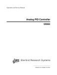
System Interconnect Drawings
COPAS BIOSORT System Interconnect Top View
COPAS BIOSORT System Interconnect Internal
COPAS Connector Panel
COPAS Fluidic Diagram
Drawings matching these part numbers / descriptions immediately following this page.
Union Biometrica, Inc. Confidential
www.unionbio.com
31
5
4
3
2
1
D
D
IBM PC
C
C
COPAS SYSTEM
DISPLAY
RUNNING
HOUSE
AIR
SER
066-0009-010
COM
RS-232 CABLE
#1
WINDOWS
IEC-320
LASER
C14 Inlet
KEYBOARD
AC CIRCUIT #1
Dedicated Line
310-5018-000
MOUSE
METAL-CLAD
FIBER-OPTIC
B
B
CABLE
CONTROL
ARGON LASER
INCLUDES SPECTRA-PHYSICS MODEL
160-SERIES AIR-COOLED ION LASER
INCLUDES 310-5010-001 LASER INTERFACE
A
AC CIRCUIT #2
Dedicated Line
IEC-320
A
C-20 Inlet
5
4
3
2
1
COPAS BIOSORT SYSTEM INTERCONNECT TOP VIEW
5
4
3
X STEPPER
2
350-5009-001
350-5010-000
1
350-5008-001
350-5011-000
D
D
EXTINCTION
PMT/HV ASSY
DETECTOR
Y STEPPER
WASTE PUMP
RED
Laser Diode
STEPPER
350-5002-001
BULKHEAD
335-5064-000
Blaster Valve
CONNECTOR
350-5001-001
C
C
SORTER
CONTROLLER
300-5055-000
Valve Assy's
B
B
CONDOR GMP130E
300-5048-000
POWER SUPPLY
STAGE ASSEMBLY
(INCLUDES 3005019-000 C/A)
CORCOM
3EP1 FILTER
310-5018-000
To Argon
Laser Assy
IEC-320
AC LINE
C14 Inlet
A
A
To PC
COM PORT
CONNECTOR
5
4
3
2
1
COPAS BIOSORT SYSTEM INTERCONNECT INTERNAL
UNION BIOMETRICA, INC.
LAST UPDATED 1/21/03
Motor #2
Aux
Mixers
Sample Valve
Stage
25
pin
25
pin
25
pin
J18
J14
J7
9
pin
Valve Panel
15
pin
15
pin
J9
EXT Laser
J8
J16
Motor #3
9
pin
Diode Laser
5
26
pin
Reflex
Power
9
pin
PMT
Assembly
J15
COPAS BIOSORT CONNECTOR PANEL (FRONT VIEW)
General Parts List
The following general parts list includes all assemblies that comprise the COPAS BIOSORT, part number
350-5000-000. For a specific bill of material for an assembly, please contact Union Biometrica, Inc.
directly.
Part No.
Description
350-5000-000
COPAS BIOSORT
300-5036-000
300-5037-000
300-5059-000
300-5061-000
300-5065-000
350-1001-000
350-1002-000
350-5020-000
350-5027-000
350-5041-000
350-5039-000
350-5021-000
350-5023-000
300-5018-000
340-5000-000
340-5001-000
Air / Regulator Filter, Assembly
Valve Panel, Assembly
Sample Bottle, Assembly
Waste Tray, Assembly
Waste Pump, Assembly
Back Plate
Base Plate
Final Optics, Assembly
System Electronics, Assembly
Sample Bottle Support, Assembly
Sample Cup, Assembly
Argon Laser System, Assembly
Laser Cover, Assembly
XY-Stage, Assembly
ReFlex Sampler, Assembly (Optional)
ReFlex Sampler Valve Panel, Assembly (Optional)
Drawings matching these part numbers / descriptions immediately following this page.
Union Biometrica, Inc. Confidential
www.unionbio.com
32
THIS DRAWING IS THE SOLE PROPERTY OF
UNION BIOMETRICA INC. AND SHALL NOT BE
REPRODUCED IN ANY FORM WHATSOEVER.
THE CONTENTS ARE FOR THE PURPOSES
ONLY OF QUOTATION TO OR MANUFACTURE
FOR UNION BIOMETRICA CORP. AND SHALL NOT
BE USED AS A BASIS FOR QUOTATION TO OR
MANUFACTURE FOR OTHERS. THIS DRAWING
SHALL BE RETURNED WITH QUOTATION OR
AT TERMINATION OF MANUFACTURING CONTRACT OR ON DEMAND OF UNION BIOMETRICA
CORP. WHICHEVER IS FIRST.
REV
1
DATE
REVISIONS & DESCRIPTION
INITIAL WORKING DRAWING
11/01/01
MADE BY APPROVED
J.M.M.
XXX
10
5
20
34
12
50
65
114
66
31
6
6
ITEM NO. QTY.
5
1
6
1
10
1
11
1
12
1
20
1
21
1
31
1
34
1
50
1
65
1
66
1
76
1
113
1
114
1
21
UNLESS OTHERWISE SPECIFIED
DIMENSIONS ARE IN INCHES
DRAWN
TOLERANCE ON
DECIMALS
FRAC
ENGINEER
.XX
.XXX
.010
.005
~
ANGLES
30'
CONCENTRICITY .005 TIR
REMOVE BURRS & SHARP EDGES
ALL FINISHED SURFACES TO BE 32
MICROINCHES UNLESS NOTED.
113
MATERIAL
350-5000-000
APPLICATION
WHERE USED
NONE
FINISH
NONE
PART NO.
300-5036-000
300-5037-000
300-5059-000
300-5061-000
300-5065-000
350-1001-000
350-1002-000
350-5020-000
350-5027-000
350-5041-000
350-5039-000
350-5023-000
300-5018-000
340-5000-000
340-5001-000
J.MESSINA
KASSEY
APPROVED
SOMERVILLE, MA. (617) 547-7703
11/01/01
.
QUALITY
ASSUR
UNION BIOMETRICA INC.
11/01/01
.
PROJECT
PROJECT
ENGR
DESCRIPTION
AIR/REGULATOR FILTER, ASSY
VALVE PANEL, ASSY
SAMPLE BOTTLE, ASSY
WASTE TRAY, ASSY
WASTE PUMP, ASSY
BACK PLATE
BASE PLATE
FINAL OPTICS, ASSY
SYSTEM ELECTRONICS, ASSY
SAMPLE BOTTLE SUPPORT, ASSY
SAMPLE CUP, ASSY
LASER COVER, ASSY
XY-STAGE, ASSY
REFLEX SAMPLER, ASSY (OPTIONAL)
REFLEX VALVE PANEL, ASSY (OPTIONAL)
TITLE:
COPAS BIOSORT
250f
QUALITY
ADDITIONAL COMMENTS:
X
REV
SIZE
D 350-5000-000
SCALE 1 : 1
DO NOT SCALE THIS DRAWING
1
SHEET 1 OF 1
REV
THIS DRAWING IS THE SOLE PROPERTY OF
UNION BIOMETRICA INC., AND SHALL NOT BE
REPRODUCED IN ANY FORM WHATSOEVER.
THE CONTENTS ARE FOR THE PURPOSES ONLY
OF QUOTATION TO OR MANUFACTURE FOR
UNION BIOMETRICA INC., AND SHALLNOT BE
USED AS A BASIS FOR QUOTATION TO OR
MANUFACTURE FOR OTHERS. THIS DRAWING
SHALL BE RETURNED WITH QUOTATION OR
AT TERMINATION OF MANUFACTURING
CONTRACT OR ON DEMAND OF UNION
BIOMETRICA INC., WHICHEVER COMES FIRST.
1
REVISIONS & DESCRIPTION
DATE
INITIAL WORKING DRAWING
MADE BY APPROVED
06/12/02
.
4
5
1
3
2
ITEM NO. QTY.
PART NO.
2
1 119-0002-001
1
1 119-0003-000
3
1 140-0002-000
4
1 140-0002-001
5
1 140-0002-002
DESCRIPTION
FITTING, THREADED ELBOW
FITTING, THREADED BARB
FILTER/REGULATER, AIR PRESSURE
BRACKET, AIR FILTER
PANEL NUT, AIR FILTER
UNLESS OTHERWISE SPECIFIED
DIMENSIONS ARE IN INCHES
TOLERANCE ON
DECIMALS
FRAC
ANGLES
+
.XX - .010
+ ~
+
+
- 30'
.XXX - .005
DRAWN
ENGINEER
APPROVED
PROJECT
.
ENGR
J.MESSINA
06/12/02
KASSEY
06/12/002
.
CONCENTRICITY .005 TIR
REMOVE BURRS & SHARP EDGES ADDITIONAL COMMENTS:
ALL FINISH SURFACES TO BE 32
X
MICRO INCHES UNLESS NOTED.
MATERIAL
TOP LEVEL
APPLICATION
WHERE USED
NONE
FINISH
NONE
.
UNION BIOMETRICA INC.
SOMERVILLE, MA. (617) 547-7703
TITLE:
QUALITY
A.NAME
ASSUR
AIR/REGULATOR,
FILTER, ASSEMBLY
SIZE
REV
PART NUMBER:
C
SCALE:NONE
300-5036-000
DO NOT SCALE THIS DRAWING
1
SHEET 1 OF 1
THIS DRAWING IS THE SOLE PROPERTY OF
UNION BIOMETRICA INC., AND SHALL NOT BE
REPRODUCED IN ANY FORM WHATSOEVER.
THE CONTENTS ARE FOR THE PURPOSES OF
QUOTATION TO OR MANUFACTURE FOR
UNION BIOMETRICA INC., AND SHALL NOT BE
USED AS A BASIS FOR QUOTATION TO OR
MANUFACTURE FOR OTHERS. THIS DRAWING
SHALL BE RETURNED WITH QUOTATION
OR AT TERMINATION OF MANUFACTURING
CONTRACT OR ON DEMAND OF UNION
BIOMETRICA INC., WHICHEVER COMES FIRST.
REV
1
.
UNLESS OTHERWISE SPECIFIED
DIMENSIONS ARE IN INCHES.
TOLERANCE ON
DECIMALS
FRAC ANGLES
.010
.005
~
30'
DRAWN
J.MESSINA
ENGINEER
.
APPROVED
.
CONCENTRICITY .005 TIR.
QUALITY
.
REMOVE BURRS & SHARP EDGES. PROJ.
ASSUR.
ENG.
ALL FINISH SURFACES TO BE 32
MICROINCHES UNLESS NOTED.
ADDITIONAL COMMENTS:
350-5000-000 MATERIAL:
APPLICATION
WHERE USED
FINISH:
NONE
NONE
.
MADE BY APPROVED
.
04/24/03 J.M.M.
.
.
INITIAL WORKING DRAWING
.
.XX
.XXX
DATE
REVISIONS & DESCRIPTION
UNION BIOMETRICA INC.
04/24/03
.
.
.
SOMERVILLE, MA. (617) 591-1211
TITLE:
ASSEMBLY,
.
VALVE PANEL
SIZE PART NUMBER:
300-5037-000
B
SCALE:
1:2
DO NOT SCALE THIS DRAWING
REV
1
SHEET 1 OF 1
THIS DRAWING IS THE SOLE PROPERTY OF
UNION BIOMETRICA INC., AND SHALL NOT BE
REPRODUCED IN ANY FORM WHATSOEVER.
THE CONTENTS ARE FOR THE PURPOSES ONLY
OF QUOTATION TO OR MANUFACTURE FOR
UNION BIOMETRICA INC., AND SHALLNOT BE
USED AS A BASIS FOR QUOTATION TO OR
MANUFACTURE FOR OTHERS. THIS DRAWING
SHALL BE RETURNED WITH QUOTATION OR
AT TERMINATION OF MANUFACTURING
CONTRACT OR ON DEMAND OF UNION
BIOMETRICA INC., WHICHEVER COMES FIRST.
REVISIONS & DESCRIPTION
REV
1
UNLESS OTHERWISE SPECIFIED
DRAWN
DIMENSIONS ARE IN INCHES
ENGINEER
TOLERANCE ON
DECIMALS
FRAC
ANGLES
APPROVED
.XX +
- .010
+ ~
+
- 30'
.XXX + .005 -
CONCENTRICITY .005 TIR
REMOVE BURRS & SHARP EDGES
ALL FINISH SURFACES TO BE 32
MICRO INCHES UNLESS NOTED.
MATERIAL
350-5000-000
APPLICATION
WHERE USED
NONE
FINISH
NONE
PROJECT
.
ENGR
DATE
07/18/02 J.M.M.
INITIAL WORKING DRAWING
J.MESSINA
07/18/02
KASSEY
07/18/02
.
.
MADE BY APPROVED
.
UNION BIOMETRICA INC.
SOMERVILLE, MA. (617) 547-7703
TITLE:
ASSEMBLY,
SAMPLE BOTTLE
QUALITY
.
ASSUR
ADDITIONAL COMMENTS:
X
SIZE
PART NUMBER:
300-5059-000
C
SCALE:
1:1
DO NOT SCALE THIS DRAWING
REV
1
SHEET 1 OF 1
THIS DRAWING IS THE SOLE PROPERTY OF
UNION BIOMETRICA INC., AND SHALL NOT BE
REPRODUCED IN ANY FORM WHATSOEVER.
THE CONTENTS ARE FOR THE PURPOSES OF
QUOTATION TO OR MANUFACTURE FOR
UNION BIOMETRICA INC., AND SHALL NOT BE
USED AS A BASIS FOR QUOTATION TO OR
MANUFACTURE FOR OTHERS. THIS DRAWING
SHALL BE RETURNED WITH QUOTATION
OR AT TERMINATION OF MANUFACTURING
CONTRACT OR ON DEMAND OF UNION
BIOMETRICA INC., WHICHEVER COMES FIRST.
REV
B
.
UNLESS OTHERWISE SPECIFIED
DIMENSIONS ARE IN INCHES.
TOLERANCE ON
DECIMALS
FRAC ANGLES
370-5000-000
350-5000-000
335-5000-000
APPLICATION
WHERE USED
.010
.005
~
30'
DRAWN
J.MESSINA
ENGINEER
KASSEY
APPROVED
.
CONCENTRICITY .005 TIR.
QUALITY
.
REMOVE BURRS & SHARP EDGES. PROJ.
ASSUR.
ENG.
ALL FINISH SURFACES TO BE 32
MICROINCHES UNLESS NOTED.
ADDITIONAL COMMENTS:
MATERIAL:
FINISH:
NONE
NONE
.
MADE BY APPROVED
.
07/19/02 J.M.M.
.
.
INITIAL WORKING DRAWING
.
.XX
.XXX
DATE
REVISIONS & DESCRIPTION
.
07/19/02
UNION BIOMETRICA INC.
07/19/02
SOMERVILLE, MA. (617) 547-7703
.
TITLE:
WASTE TRAY,
.
ASSEMBLY
SIZE PART NUMBER:
300-5061-000
B
SCALE:
1:1
DO NOT SCALE THIS DRAWING
REV
B
SHEET 1 OF 1
REV
THIS DRAWING IS THE SOLE PROPERTY OF
UNION BIOMETRICA INC., AND SHALL NOT BE
REPRODUCED IN ANY FORM WHATSOEVER.
THE CONTENTS ARE FOR THE PURPOSES ONLY
OF QUOTATION TO OR MANUFACTURE FOR
UNION BIOMETRICA INC., AND SHALLNOT BE
USED AS A BASIS FOR QUOTATION TO OR
MANUFACTURE FOR OTHERS. THIS DRAWING
SHALL BE RETURNED WITH QUOTATION OR
AT TERMINATION OF MANUFACTURING
CONTRACT OR ON DEMAND OF UNION
BIOMETRICA INC., WHICHEVER COMES FIRST.
1
REVISIONS & DESCRIPTION
DATE
INITIAL WORKING DRAWING
06/11/02
MADE BY APPROVED
J.M.M.
14
12
15
10
13
5
4
ITEM NO. QTY.
PART NO.
DESCRIPTION
4
1
070-0020-002 MOTOR, STEPPER
5
4
131-0440-009 SCREW, PH, #4-40 X 7/16"
6
2
131-0832-001 SCREW, PH, #8-32 X 1/2"
10
3
139-0003-001 MOUNT, ISOLATION
11
4
300-1061-000 PIN, ROLLAR
12
1
300-1062-000 MOUNT, PUMP MOTOR
13
1
300-1063-000 PLATE, PUMP SUPPORT
14
4
300-1064-000 ROLLER, PUMP
15
1
350-1022-000 ROTOR
UNLESS OTHERWISE SPECIFIED
DIMENSIONS ARE IN INCHES
TOLERANCE ON
DECIMALS
FRAC
ANGLES
+
.XX - .010
+ ~
+
+
- 30'
.XXX - .005
DRAWN
ENGINEER
J.MESSINA
06/11/02
KASSEY
06/11/002
APPROVED
PROJECT
A.NAME
ENGR
.
CONCENTRICITY .005 TIR
REMOVE BURRS & SHARP EDGES ADDITIONAL COMMENTS:
ALL FINISH SURFACES TO BE 32
X
MICRO INCHES UNLESS NOTED.
MATERIAL
TOP LEVEL
APPLICATION
WHERE USED
NONE
FINISH
NONE
.
UNION BIOMETRICA INC.
SOMERVILLE, MA. (617) 547-7703
TITLE:
WASTE PUMP
QUALITY
A.NAME
ASSUR
ASSEMBLY
SIZE
REV
PART NUMBER:
C
SCALE: NONE
300-5065-000
DO NOT SCALE THIS DRAWING
1
SHEET 1 OF 1
THIS DRAWING IS THE SOLE PROPERTY OF
UNION BIOMETRICA INC. AND SHALL NOT BE
REPRODUCED IN ANY FORM WHATSOEVER.
THE CONTENTS ARE FOR THE PURPOSES
ONLY OF QUOTATION TO OR MANUFACTURE
FOR UNION BIOMETRICA INC. AND SHALL NOT
BE USED AS A BASIS FOR QUOTATION TO OR
MANUFACTURE FOR OTHERS. THIS DRAWING
SHALL BE RETURNED WITH QUOTATION OR
AT TERMINATION OF MANUFACTURING CONTRACT OR ON DEMAND OF UNION BIOMETRICA
INC., WHICHEVER IS FIRST.
REV
1
DATE
REVISIONS & DESCRIPTION
INITIAL WORKING DRAWING
06/26/01
MADE BY APPROVED
J.M.M.
6
4
5
ITEM NO.
4
5
6
QTY.
1
1
1
PART NO.
350-5014-000
350-5006-000
350-5005-000
DESCRIPTION
UNION BIOMETRICA INC.
ENGINEER
KASSEY
06/26/01
SOMERVILLE, MA. (617) 547-7703
APPROVED
.
TOLERANCE ON
DECIMALS
FRAC
.010
.005
~
ANGLES
30'
360-5000-000
CONCENTRICITY .005 TIR
REMOVE BURRS & SHARP EDGES
ALL FINISH SURFACES TO BE 32
MICRO INCHES UNLESS NOTED.
350-5000-000
MATERIAL
335-5000-000
APPLICATION
WHERE USED
06/26/01
DRAWN
.XX
.XXX
370-5000-000
J.MESSINA
UNLESS OTHERWISE SPECIFIED
DIMENSIONS ARE IN INCHES
NONE
FINISH
NONE
PROJECT
D.PERRAULT
ENGR
.
ASSEMBLY,
FINAL OPTICS
QUALITY
.
ASSUR
ADDITIONAL COMMENTS:
X
REV
SIZE
350-5020-000
SCALE 1 : 1
DO NOT SCALE THIS DRAWING
1
SHEET 1 OF 1
THIS DRAWING IS THE SOLE PROPERTY OF
UNION BIOMETRICA INC., AND SHALL NOT BE
REPRODUCED IN ANY FORM WHATSOEVER.
THE CONTENTS ARE FOR THE PURPOSES ONLY
OF QUOTATION TO OR MANUFACTURE FOR
UNION BIOMETRICA INC., AND SHALLNOT BE
USED AS A BASIS FOR QUOTATION TO OR
MANUFACTURE FOR OTHERS. THIS DRAWING
SHALL BE RETURNED WITH QUOTATION OR
AT TERMINATION OF MANUFACTURING
CONTRACT OR ON DEMAND OF UNION
BIOMETRICA INC., WHICHEVER COMES FIRST.
REVISIONS & DESCRIPTION
REV
1
UNLESS OTHERWISE SPECIFIED
DRAWN
DIMENSIONS ARE IN INCHES
ENGINEER
TOLERANCE ON
DECIMALS
FRAC
ANGLES
APPROVED
.XX +
- .010
+ ~
+
- 30'
.XXX + .005 -
CONCENTRICITY .005 TIR
REMOVE BURRS & SHARP EDGES
ALL FINISH SURFACES TO BE 32
MICRO INCHES UNLESS NOTED.
MATERIAL
350-5000-000
APPLICATION
WHERE USED
NONE
FINISH
NONE
PROJECT
.
ENGR
DATE
04/22/03 J.M.M.
INITIAL WORKING DRAWING
J.MESSINA
.
.
.
UNION BIOMETRICA INC.
04/21/03
SOMERVILLE, MA. (617) 591-1211
.
.
MADE BY APPROVED
TITLE:
QUALITY
.
ASSUR
ADDITIONAL COMMENTS:
ASSEMBLY,
SYSTEM ELECTRONICS PANEL
X
SIZE
PART NUMBER:
350-5027-000
C
SCALE:
1:2
DO NOT SCALE THIS DRAWING
REV
1
SHEET 1 OF 1
THIS DRAWING IS THE SOLE PROPERTY OF
UNION BIOMETRICA INC., AND SHALL NOT BE
REPRODUCED IN ANY FORM WHATSOEVER.
THE CONTENTS ARE FOR THE PURPOSES OF
QUOTATION TO OR MANUFACTURE FOR
UNION BIOMETRICA INC., AND SHALL NOT BE
USED AS A BASIS FOR QUOTATION TO OR
MANUFACTURE FOR OTHERS. THIS DRAWING
SHALL BE RETURNED WITH QUOTATION
OR AT TERMINATION OF MANUFACTURING
CONTRACT OR ON DEMAND OF UNION
BIOMETRICA INC., WHICHEVER COMES FIRST.
REV
1
3
DATE
REVISIONS & DESCRIPTION
.
07/24/02 J.M.M.
.
.
INITIAL WORKING DRAWING
.
.
MADE BY APPROVED
.
2
4
UNLESS OTHERWISE SPECIFIED
DIMENSIONS ARE IN INCHES.
TOLERANCE ON
DECIMALS
FRAC ANGLES
.XX
.XXX
ITEM NO. QTY. PART NO.
DESCRIPTION
1
1 300-1042-000 RING, SAMPLE BOTTLE SUPPORT
2
1 350-1003-000 PLATE, SAMPLE BOTTLE
3
2 300-1044-000 BRACKET, SUPPORT
360-5000-000
.010
.005
30'
J.MESSINA
ENGINEER
KASSEY
APPROVED
.
CONCENTRICITY .005 TIR.
QUALITY
.
REMOVE BURRS & SHARP EDGES. PROJ.
ASSUR.
ENG.
ALL FINISH SURFACES TO BE 32
MICROINCHES UNLESS NOTED.
ADDITIONAL COMMENTS:
350-5000-000 MATERIAL:
APPLICATION
WHERE USED
~
DRAWN
FINISH:
NONE
NONE
.
07/24/02
UNION BIOMETRICA INC.
07/24/02
SOMERVILLE, MA. (617) 547-7703
.
TITLE:
SUPPORT ASSEMBLY,
.
SAMPLE BOTTLE
SIZE PART NUMBER:
350-5041-000
B
SCALE:
NONE
DO NOT SCALE THIS DRAWING
REV
1
SHEET 1 OF 1
THIS DRAWING IS THE SOLE PROPERTY OF
UNION BIOMETRICA INC., AND SHALL NOT BE
REPRODUCED IN ANY FORM WHATSOEVER.
THE CONTENTS ARE FOR THE PURPOSES OF
QUOTATION TO OR MANUFACTURE FOR
UNION BIOMETRICA INC., AND SHALL NOT BE
USED AS A BASIS FOR QUOTATION TO OR
MANUFACTURE FOR OTHERS. THIS DRAWING
SHALL BE RETURNED WITH QUOTATION
OR AT TERMINATION OF MANUFACTURING
CONTRACT OR ON DEMAND OF UNION
BIOMETRICA INC., WHICHEVER COMES FIRST.
REV
1
.
UNLESS OTHERWISE SPECIFIED
DIMENSIONS ARE IN INCHES.
TOLERANCE ON
DECIMALS
FRAC ANGLES
.010
.005
~
30'
DRAWN
J.MESSINA
ENGINEER
KASSEY
APPROVED
.
CONCENTRICITY .005 TIR.
QUALITY
.
REMOVE BURRS & SHARP EDGES. PROJ.
ASSUR.
ENG.
ALL FINISH SURFACES TO BE 32
MICROINCHES UNLESS NOTED.
ADDITIONAL COMMENTS:
350-5000-000 MATERIAL:
APPLICATION
WHERE USED
FINISH:
NONE
NONE
.
MADE BY APPROVED
.
07/15/02 J.M.M.
.
.
INITIAL WORKING DRAWING
.
.XX
.XXX
DATE
REVISIONS & DESCRIPTION
UNION BIOMETRICA INC.
07/15/02
07/15/02
.
.
SOMERVILLE, MA. (617) 591-1211
TITLE:
ASSEMBLY,
.
SAMPLE CUP
SIZE PART NUMBER:
350-5039-000
B
SCALE:
1:2
DO NOT SCALE THIS DRAWING
REV
1
SHEET 1 OF 1
THIS DRAWING IS THE SOLE PROPERTY OF
UNION BIOMETRICA INC., AND SHALL NOT BE
REPRODUCED IN ANY FORM WHATSOEVER.
THE CONTENTS ARE FOR THE PURPOSES ONLY
OF QUOTATION TO OR MANUFACTURE FOR
UNION BIOMETRICA INC., AND SHALLNOT BE
USED AS A BASIS FOR QUOTATION TO OR
MANUFACTURE FOR OTHERS. THIS DRAWING
SHALL BE RETURNED WITH QUOTATION OR
AT TERMINATION OF MANUFACTURING
CONTRACT OR ON DEMAND OF UNION
BIOMETRICA INC., WHICHEVER COMES FIRST.
REVISIONS & DESCRIPTION
REV
1
UNLESS OTHERWISE SPECIFIED
DRAWN
DIMENSIONS ARE IN INCHES
ENGINEER
TOLERANCE ON
DECIMALS
FRAC
ANGLES
APPROVED
.XX +
- .010
+ ~
+
- 30'
.XXX + .005 -
CONCENTRICITY .005 TIR
REMOVE BURRS & SHARP EDGES
ALL FINISH SURFACES TO BE 32
MICRO INCHES UNLESS NOTED.
MATERIAL
ALL
APPLICATION
WHERE USED
NONE
FINISH
NONE
PROJECT
.
ENGR
DATE
04/22/02 J.M.M.
INITIAL WORKING DRAWING
J.MESSINA
04/22/02
KASSEY
04/22/02
.
.
MADE BY APPROVED
.
UNION BIOMETRICA INC.
SOMERVILLE, MA. (617) 591-1211
TITLE:
ASSEMBLY,
ARGON LASER SYSTEM
QUALITY
.
ASSUR
ADDITIONAL COMMENTS:
X
SIZE
PART NUMBER:
350-5021-000
C
SCALE:
1:3
DO NOT SCALE THIS DRAWING
REV
1
SHEET 1 OF 1
THIS DRAWING IS THE SOLE PROPERTY OF
UNION BIOMETRICA INC., AND SHALL NOT BE
REPRODUCED IN ANY FORM WHATSOEVER.
THE CONTENTS ARE FOR THE PURPOSES OF
QUOTATION TO OR MANUFACTURE FOR
UNION BIOMETRICA INC., AND SHALL NOT BE
USED AS A BASIS FOR QUOTATION TO OR
MANUFACTURE FOR OTHERS. THIS DRAWING
SHALL BE RETURNED WITH QUOTATION
OR AT TERMINATION OF MANUFACTURING
CONTRACT OR ON DEMAND OF UNION
BIOMETRICA INC., WHICHEVER COMES FIRST.
REV
1
.
UNLESS OTHERWISE SPECIFIED
DIMENSIONS ARE IN INCHES.
TOLERANCE ON
DECIMALS
FRAC ANGLES
.010
.005
~
30'
DRAWN
J.MESSINA
ENGINEER
.
APPROVED
.
CONCENTRICITY .005 TIR.
QUALITY
.
REMOVE BURRS & SHARP EDGES. PROJ.
ASSUR.
ENG.
ALL FINISH SURFACES TO BE 32
MICROINCHES UNLESS NOTED.
ADDITIONAL COMMENTS:
350-5000-000 MATERIAL:
APPLICATION
WHERE USED
FINISH:
NONE
NONE
.
MADE BY APPROVED
.
02/05/03 J.M.M.
.
.
INITIAL WORKING DRAWING
.
.XX
.XXX
DATE
REVISIONS & DESCRIPTION
UNION BIOMETRICA INC.
02/05/03
.
.
.
SOMERVILLE, MA. (617) 591-1211
TITLE:
ASSEMBLY,
.
LASER COVER
SIZE PART NUMBER:
350-5023-000
B
SCALE:
1:2
DO NOT SCALE THIS DRAWING
REV
1
SHEET 1 OF 1
REV
THIS DRAWING IS THE SOLE PROPERTY OF
UNION BIOMETRICA INC., AND SHALL NOT BE
REPRODUCED IN ANY FORM WHATSOEVER.
THE CONTENTS ARE FOR THE PURPOSES ONLY
OF QUOTATION TO OR MANUFACTURE FOR
UNION BIOMETRICA INC., AND SHALLNOT BE
USED AS A BASIS FOR QUOTATION TO OR
MANUFACTURE FOR OTHERS. THIS DRAWING
SHALL BE RETURNED WITH QUOTATION OR
AT TERMINATION OF MANUFACTURING
CONTRACT OR ON DEMAND OF UNION
BIOMETRICA INC., WHICHEVER COMES FIRST.
C
REVISIONS & DESCRIPTION
DATE
INITIAL WORKING DRAWING
MADE BY APPROVED
06/03/02
.
32
32
11
12
16
8
21
18
35
14
11
10
18
16
16
18
9
21
13
51
19
17
31
17
10
14
17
17
ITEM NO. QTY.
PART NO.
DESCRIPTION
8
2
300-1001-000 BRACKET, LEFT SIDE MOUNTING
9
2
300-1002-000 BRACKET, RIGHT SIDE MOUNTING
10
2
300-1003-000 ROD, Y-STAGE TRAVERSE
11
2
300-1004-000 ROD, Y-STAGE TRAVERSE
12
1
300-1005-000 BRACKET, Y-STAGE TOP MOUNTING
13
1
300-1006-000 BRACKET, X-STAGE TOP MOUNTING
14
2
300-1009-000 BRACKET, MOTOR MOUNTING
16
4
300-1011-000 BEARING, LARGE MOTOR MOUNTING
17
4
300-1012-000 BEARING, SMALL MOTOR MOUNTING
18
4
300-1013-000 VANE, HALL-EFFECT
19
1
300-1014-000 BASEPLATE, X-STAGE
20
1
300-1046-000 COVER, X-STAGE CONNECTOR
32
2
300-1100-000 PLATE, LOCATOR
51
1
300-1103-000 COVER, PCB, X-Y STAGE
21
4
300-5011-000 ASSEMBLY, PCB, LIMIT SENSOR
31
1
300-5024-000 ASSEMBLY, MOTOR, Y-STAGE
35
1
300-5025-000 ASSEMBLY, MOTOR, X-STAGE
8
20
9
21
UNLESS OTHERWISE SPECIFIED
DIMENSIONS ARE IN INCHES
TOLERANCE ON
DECIMALS
FRAC
ANGLES
.XX +
- .010
+ ~
+
+ .005
- 30'
.XXX -
DRAWN
J.MESSINA
06/03/02
ENGINEER
KASSEY
06/03/02
APPROVED
.
.
PROJECT
MATERIAL
TOP LEVEL
APPLICATION
WHERE USED
FINISH
NONE
NONE
SOMERVILLE, MA. (617) 547-7703
TITLE:
X-Y STAGE
ASSEMBLY
QUALITY
.
ASSUR
.
ENGR
CONCENTRICITY .005 TIR
REMOVE BURRS & SHARP EDGES ADDITIONAL
ALL FINISH SURFACES TO BE 32
X
MICRO INCHES UNLESS NOTED.
UNION BIOMETRICA INC.
COMMENTS:
SIZE
REV
PART NUMBER:
C
SCALE:NONE
300-5018-000
DO NOT SCALE THIS DRAWING
C
SHEET 1 OF 1
THIS DRAWING IS THE SOLE PROPERTY OF
UNION BIOMETRICA INC. AND SHALL NOT BE
REPRODUCED IN ANY FORM WHATSOEVER.
THE CONTENTS ARE FOR THE PURPOSES
ONLY OF QUOTATION TO OR MANUFACTURE
FOR UNION BIOMETRICA INC. AND SHALL NOT
BE USED AS A BASIS FOR QUOTATION TO OR
MANUFACTURE FOR OTHERS. THIS DRAWING
SHALL BE RETURNED WITH QUOTATION OR
AT TERMINATION OF MANUFACTURING CONTRACT OR ON DEMAND OF UNION BIOMETRICA
INC., WHICHEVER IS FIRST.
REV
1
18
DATE
REVISIONS & DESCRIPTION
INITIAL WORKING DRAWING
11/30/01
MADE BY APPROVED
J.M.M.
27
19
28
24
26
9
32
22
30
20
23
ITEM NO. QTY. PART NO.
9
1 300-1013-000
18
1 340-1006-000
19
1 340-1001-000
20
1 340-1002-000
21
1 340-1004-000
22
1 340-1007-000
23
1 340-1003-000
24
1 340-1012-000
26
1 300-5011-000
27
2 340-1010-000
28
1 340-1005-000
29
1 070-0040-002
30
1 199-0006-002
31
1 199-0006-001
32
1 120-0003-003
33
1 340-1008-000
21
29
11/30/01
UNION BIOMETRICA INC.
ENGINEER
KASSEY
11/30/01
SOMERVILLE, MA. (617) 547-7703
APPROVED
.
DRAWN
TOLERANCE ON
DECIMALS
FRAC
.XX
.XXX
.010
.005
~
ANGLES
30'
CONCENTRICITY .005 TIR
REMOVE BURRS & SHARP EDGES
ALL FINISH SURFACES TO BE 32
MICRO INCHES UNLESS NOTED.
MATERIAL
340-5000-000
APPLICATION
WHERE USED
J.MESSINA
UNLESS OTHERWISE SPECIFIED
DIMENSIONS ARE IN INCHES
NONE
FINISH
NONE
PROJECT
.
ENGR
.
QUALITY
A.NAME
ASSUR
SAMPLER, ASSEMBLY
ADDITIONAL COMMENTS:
X
REV
SIZE
C
340-5000-000
SCALE 1 : 2
DO NOT SCALE THIS DRAWING
1
SHEET 1 OF 1
Printed Circuit Boards
Assembly #
Description
310-5010-000
340-5005-000
350-5001-000
350-5002-000
350-5008-000
350-5009-000
Laser Interface
ReFlx Sampler
Sorter Controller
Bulkhead Connector
Extinction Detector
PMT Preamp/HV
Board
Revision No.
Rev B
Rev B
Rev D
Rev A
Rev A
Rev A
Parts List
Revision No.
Rev C2
Rev 4
Rev D1
Rev A3
Rev A3
Rev A1
Notes
ReFlx option
Drawings matching these part numbers / descriptions immediately following this page.
Major Cable Assemblies
Assembly #
Description
300-5019-000
300-5048-000
300-5055-000
310-5018-000
335-5064-000
340-5006-000
340-5007-000
350-5010-000
350-5011-000
350-5012-000
350-5013-000
XY Internal C/A
Stage C/A
Valve Panel C/A
Laser Control
Blaster C/A
Frontside C/A
Backside C/A
PMT C/A
Detector C/A
Stirrer C/A
Sheath C/A
Union Biometrica, Inc. Confidential
www.unionbio.com
Board
Revision No.
Rev A
Rev A
Rev A
Rev A
Rev A
Rev 5
Rev 7
Rev 1
Rev 2
Rev 2
Rev 2
Parts List
Revision No.
Rev A
Rev A
Rev A
Rev A
Rev A
Rev 5
Rev 5
Rev 1
Rev 2
Rev 2
Rev 2
Notes
ReFlx option
ReFlx option
33
8
7
6
5
4
3
2
1
REV
ECN NO.
APPROVAL
DATE
STANDARD JUMPER CONFIGURATION
VCC1
JP1 Not Installed,
JP1: (External Interlock Switch Active) NOT installed
JP2 Installed.
P6
TO INTERLOCK
SWITCH
JP2: (Ignore 'Interlock OK') INSTALLED
REL1
14
1
2
1
2
D6
1N4148
VCC1
CON2
JP1
D
GND1
6
7
8
JP2
JP3: (Force Local Mode) INSTALLED
OC1
8
7
6
5
R1
1K
2
3
GND2
HCPL-2211
D
REED RELAY
Force Local Mode
(Installed)
JP3
INTLK_OFF/ON#
GND1
Y1
Y2
Y3
Y4
Y5
Y6
A1
A2
A3
A4
A5
A6
TO LASER
POWER SUPPLY
GND1
INTLK_OK/OFF#
1K
R2
2
3
VCC2
VALVE10
PWR/CUR#_SEL2
VALVE11
STANDBY/RUN2#
VALVE12
DIS_OFF/EN2#
1
9
2
10
3
11
4
12
5
13
6
14
7
15
8
HCPL-2211
OC3
8
7
6
5
VCC1
74AHC04
PWR/CUR#_SEL1
GND1
1K
R3
2
3
VCC2
LASERMON
SET
RUN/STANDBY1#
HCPL-2211
CURRENT_MONITOR
POWER_MONITOR
1Y
1A
1B
PWRCTL
5
2Y
2A
2B
1
2
GND1
6
7
VCC2
8
7
6
5
DIS_EN/OFF1#
U3
3
OC4
VCC1
STANDBY/RUN1#
TO J9 ON BULKHEAD PANEL
Via 310-5018-000 C/A (1:1)
1K
R4
2
3
DB15
VCC2
1
Via 310-5017-000 Cable
P3
8
7
6
5
CUR/PWR#_SEL1
1
3
5
9
11
13
J1
1
9
2
10
3
11
4
12
5
13
6
14
7
15
8
OC2
VCC1
U2
2
4
6
8
10
12
GND2
HCPL-2211
DIS_OFF/EN1#
TP6
CON1
SN75462
MONITOR
DB15
GND1
GND1
GND2
VCC2
VCC2
GAIN
VCC2
R16
499R
OC5
GND1
Radded
4
3
2
1
4.99K
4.99K added 6/7/01
VCC
to desensitize POT1
R11
adjustment range.
C
GND1
POT1
200K
10K
Q1
2N3906
2
8
R30
VDD
VSS
VL
GND
GND2
GND2
NOTE: GND1, GND2, VCC1, VCC2 ARE
VCC1
GND1
GND2
R22
499R
R24
+12V
VCC1
VCC2
VCC2
PWRCTL
DVM
TP1
CON1
TP2
CON1
TP3
CON1
TP4
CON1
HCNR200
CAL
VCC
69.8K
Q5
2N3904
Q7
2N3904
Q8
2N3906
POT2
200K
Q6
2N3906
GND1
VCC1
GND1
R21
10R
DIS_EN/OFF1#
C13
.33
C14
.33
C15
.33
C16
.33
C27
.33
C29
R27
10K
4
3
2
1
1
5
6
7
8
R23
10K
1
POT3
200K
VCC1
.33
ALL ISOLATED IN CLAD
GND2
OC6
GND1
1
2
3
4
2
3
4
GND1
1
1
VCC1
R17
10R
1
Hour Meter
ORN
BLK
WHI
RED
Q3
2N3906
R13
10R
VCC1
P5
1
2
4
5
R12
10K
VCC1
GND1
VCC1
GND1
C12
GND2
1
4
7
5
3
C11
.33
C
Q4
2N3904
ADG419
CON10
Curtis #701 RR 601 00512D
D
.33
C17
22
69.8K
+12V
GND1
VCC1
1
2
3
4
5
6
7
8
9
10
PANEL METER
+
R14
Q2
2N3904
IN
10K
P4
TO DIGITAL
S1
S2
6
R15
10K
HCNR200
U1
PWR/CUR#_SEL1
5
6
7
8
R25
10R
GND1
GND2
GND1
GND1
GND2
GND2
SET GAIN
R26
10K
VCC1
(See ECO Note)
GND1
+12V
+12V
GND
CON4
B
SHOWN FOR REFERENCE ONLY
ORN
1
RED
5
(NC)
3
2
BLK
4
WHI
GND1
GND1
GND2
VCC2
Q12
DIS_EN/OFF1#
VCC1
VR1
LM7805
1
+12V
3
OUT
VCC1
+
GND
C22
22
TR
Q
DIS
8
Q11
2N3904
5
10K
GND1
R
2
.01
DIS_OFF/EN1#
("Slo-Blo") with appropriate agency recognition. Variation
from these values will result in either unreliable operation,
1N4148
Q13
TP5
CON1
R31
is 200 mA. In both cases, the fuses must be Type T
D2
CV
THR
D3
3
7
1N4148
IRLD024
6
R36
10K
R32
GND1
or unsafe operation.
C25
.01
10K
GND1
The silkscreen text is in error.
U4
NE555
C26
220uF
GND1
GND1
GND1
GND1
ECO Note:
F1
A
SEE NOTE
6
RS1A
T1
12
4
3
10
9
-
+
VCC1
3
1
7
5
Union Biometrica Inc.
35 Medford Street, Suite 101
Somerville, MA 02143
LED4
CUR/PWR#_SEL1
6
DATE
330R I8
AMBER
R41
LED5
Title
GND1
INTLK_OFF/ON#
VCC1
DATE
332
7
Laser Interface
CHECKED BY
CON1
8
Panel. (Conflict with sheath pump motor control)
STANDBY/RUN1#
AMBER
RS1C
GT1
EGND
it to ground at the J9 connector on the Bulkhead
DRAWN BY
VCC1
VPP10-3000
6
A
drive signal by removing the driven end, and shorting
LED3
4
330R I8
C23
1000uF
DIS_OFF/EN1#
AMBER
RS1B
+12V
+
An ECO of May '01 effectively disabled the SET
LED2
2
330R I8
GND1
CON6
1
1
RS402LD
6
5
4
3
2
1
AC MAIN
VCC1
DB1
P1
TO
TO FANS
22uF
C24
RS1D
330R I8
R35
1M
1
2
3
CON3
4
1
GND1
100 mA. For 120V systems, the correct amperage rating
D5
MUR120
GND1
+
R34
10K
10K
7
GND1
+12V
VCC1
C28
R33
GND1
F1. For 230V systems, the correct amperage rating is
R42
10K
VCC1
LED1
GREEN
2
CE compliance requires that the correct fuse be used at
P7
+12V
VCC1
C21
.33
IMPORTANT FUSE NOTE:
IRLD024
GND1
IN
B
D4
MUR120
Size
C
Document Number
Date:
Tuesday, April 29, 2003
5
4
3
2
Rev
310-5010-SC0
AMBER
B
Sheet
1
of
1
1
COPAS BIOSORT LASER INTERFACE
5
4
3
2
1
+5
2
+24
D1
+3.3
P4
V6#
USB Bus
COPAS
Powered
Powered
1
PE[0..7]
PE[0..7]
+24
R1
42
31
18
7
U2
74LCX16244
PE[0..7]
D
PB[0..4]
PB[0..4]
+
+
+
+
PE7
PE6
PE5
PE4
47
46
44
43
1
PB[0..4]
PB4
41
40
38
37
48
V2#
V1#
V0#
+24
O8
O9
O10
O11
I12
I13
I14
I15
OE4#
O12
O13
O14
O15
-
RP3
8
7
6
5
19
20
22
23
1.8K I8
1
2
3
4
C17
TP4
120uF/50V
5R
U5
74AHCT14
1
3
5
9
11
13
45
-
-
C23
C18
2
4
6
8
10
12
+3.3
5R
OI
5
+5
4
499R
LCX14
R3
12
LIMSW
ISPOWERED#
R16
2
IO
20.0K
G
C20
0.22/50V
R17
LCX14
R14
237R
1
R11
+5
1
LCX14
R100
237R
2
4.99K
PB
PB
Bsen
/PB
/PB
DIR
EN
PA
PA
Asen
/PA
/PA
H/F
Iadj
C14
5R
1
C1+
Vcc
22uF/35V
C32
4
5R
5R
0.1
C34
10
9
JP100
PB3
PB2
499R
499R
+3.3
X0
A
X1
= 340mA/winding
TP1
CGRID-8M
C8
0.22/50V
0.1
C19
0.22/50V
C1
0.22/50V
5R
5R
5R
CGRID-4M
5R
RIX1
TOX1
1
2
3
4
A
MNT1
MNT2
MNT3
MNT4
U3B
IB462H
25
24
23
22
1
1
5R
1
CGRID-8M
LTC1386CS/MAX3232
P101
Title
ReFlx Sampler Board - Peripheral Drivers
5R
DO NOT POPULATE
Size
Date:
4
3
Document Number
B
5R
5
CAVRO PUMPS
C31
GND
47R
47R
+5
2
GND
47R
R101
V+
+5
1
2
3
4
5
6
7
8
4.99K
R102
V-
1
2
3
4
5
6
7
8
7
8
1
X4
T2in T2out
R2out R2in
GND
X3
R103
T1in T1out
R1out R1in
P3
+24
14
13
P100
4.99K
R104
0.1
C2-
GND
X2
R105
ALT FUNC
B
1
R107
C35
5R
5
15
R106
6
1 2
3 4
C1-
GND
+3.3
U3A
0.1
3
11
12
TX0
RX0
TP3
Vsetpoint : 170mV
5R
0.1
CGRID-10M
PHASE A
1
U11
C2+
C30
5R
16
15
+
0.22/50V
+5
19
20
21
17
18
C
IB462H
16
C21
C6
0.22/50V
5R
PHASE B
TP2
1
LIMSW
+3.3
B
11
12
8
9
10
/R
10.0K
7
+3.3
Vsetpoint
+5
4.99K
3
SClk
1
2
3
4
5
6
7
8
9
10
0V
IO
13
2
+5V
0V
OI
PB7
JP101
JUMPER
R12
U10A
PB6
10
+
11
1
5R
4.99K
BLIMSW
14
U10F
LCX14
U10E
X1
R13
10.0K
+5
PB5
4
TO STEPPER
5R
P1
R2
+3.3
0.22/50V
22uF/35V
7
39
34
28
21
15
10
3
CGRID-6M
+24
5R
+5
7
X0
+5
CGRID-10M
5R
PB[5..7]
POWER IN
6
5
4
3
2
1
+V
I8
I9
I10
I11
OE3#
PB[5..7]
U10B
P2
+24
5R
X2
X3
X4
PB3
13
14
16
17
6
PB[5..7]
D
TO VALVES
1
2
3
4
5
6
7
8
9
10
V3#
14
4
10
COM
V6#
V5#
+V
PC[2..5]
PC[2..5]
V4#
18
17
16
15
14
13
12
11
01
02
03
04
05
06
07
08
13
PC[2..5]
1.8K I8
1
2
3
4
I1
I2
I3
I4
I5
I6
I7
I8
+
C
8
9
11
12
RP2
8
7
6
5
1
2
3
4
5
6
7
8
1
30
29
27
26
24
1.8K I8
1
2
3
4
14
PC3
PC4
PC5
PC2
O4
O5
O6
O7
RP1
8
7
6
5
P5
+
36
35
33
32
25
I4
I5
I6
I7
OE2#
2
3
5
6
CGRID-4M
499R
9
PB0
PB1
PB2
O0
O1
O2
O3
0V
PE3
PE2
PE1
PE0
VALVEN#
PB3
I0
I1
I2
I3
OE1#
U1
62081
EXPANDER
1
2
3
4
V5#
HEARTBEAT
2
Tuesday, April 29, 2003
Rev
340-5005-SCO
Sheet
1
B1
1
of
2
REFLEX SAMPLER OPTIONAL MODULE PAGE 1
5
4
3
2
1
Y1
x1
x2
C25
C26
+3.3
12 MHz
27pF
BUFRST#
+3.3
R8
5R
5R
1M
H2
3
Q1
R4
C28
C16
R20
1M
0.1
GND
C
GND
D
53
54
A
GND
B
GND
8
7
6
5
C9
0.1
C11
0.1
5R
73
74
5R
76
77
5R
U6
C15
U8
+
5
8
7
2
0.22/50V
5R
128Kx8 SRAM
5R
8
24
+3.3
MAX882
IN
LBI
#STBY
SET
OUT
LBO
GND
GND
4
1
3
6
5
R19
+
100K
C29
22uF/35V
A0
A1
A2
A3
A4
A5
A6
A7
A8
A9
A10
A11
A12
A13
A14
A15
VDD
VDD
CE
5R
5R
5R
5R
+3.3
RP4
16
15
14
13
12
11
10
9
B
1
2
3
4
5
6
7
8
PB4
H1
AOE#
OE#
BSEL
ASEL
XCLK
R9
H1
32
WR#
12
28
22.1R
9
25
R22
100K
U10C
S1
+3.3
5
RP6
1
2
3
4
5
6
7
8
16
15
14
13
12
11
10
9
OI
U10D
6
LCX14
SA0
WR#
RD#
9
OI
5R
LCX14
6
7
10
11
22
23
26
27
D0
D1
D2
D3
D4
D5
D6
D7
8
9
10
11
13
14
15
16
EA
XCLK
R10
22.1R
CLKOUT
C33
WAKEUP#
+3.3
+3.3
PC0/RxD0
PC1/TxD0
PC2/INT0#
PC3/INT1#
PC4/T0
PC5/T1
PC6/WR#
PC7/RD#
A0
A1
A2
A3
A4
A5
A6
A7
A8
A9
A10
A11
A12
A13
A14
A15
C3
C5
0.1
0.1
0.1
0.1
D0
D1
D2
D3
D4
D5
D6
D7
PE0
PE1
PE2
PE3
PE4
PE5
PE6
PE7
BKPT
PSEN#
adr5
EA
XCLK
CLKOUT
WAKEUP#
RDY0/ASEL
RDY1/BSEL
RDY2/AOE
RDY3/BOE
RDY4/SLWR
RDY5/SLRD
CTL0/AINFLAG
CTL1/BINFLAG
CTL2/AOUTFLAG
SCL
SDA
PA0
PA1
OE#
PA3
PA4
PA5
PA6
PA7
79
80
81
82
83
84
85
86
PB0
PB1
PB2
PB3
PB4
PB5
PB6
PB7
110
111
112
113
123
124
125
126
RX0
TX0
PC2
PC3
PC4
PC5
WR#
RD#
56
57
58
59
60
61
63
64
PD0
PD1
PD2
PD3
PD4
PD5
PD6
PD7
88
89
90
91
92
93
94
95
PE0
PE1
PE2
PE3
PE4
PE5
PE6
PE7
PB[0..4]
PB[0..4]
PB[5..7]
PC[2..5]
PE[0..7]
PE[0..7]
+3.3
J3
5R
102
103
104
44
45
46
ASEL
BSEL
AOE#
BOE#
SLWR
SLRD
101
96
97
BINFLAG
SCL
PA0
PA1
PA3
PA4
PA5
PA6
PA7
2
4
6
8
10
12
14
16
18
20
5R
(H1)
+
+
+
+
+
+
+
+
+
+
+
+
+
+
+
+
+
+
+
+
5R
PC5
PC4
PC3
PC2
BSEL
BINFLAG
SLRD
SLWR
1K
2
4
6
8
10
12
14
16
18
20
H3
XCLKSEL
5R
1
3
5
7
9
11
13
15
17
19
SDA
XCLK
BUFRST#
B
RD#
BOE#
5R
CLKOUT
3M-20
+3.3
J2
(H2)
+
+
+
+
+
+
+
+
+
+
+
+
+
+
+
+
+
+
+
+
1
3
5
7
9
11
13
15
17
19
PD7
PD6
PD5
PD4
PD3
PD2
PD1
PD0
5R
A
3M-20
5R
5R
5R
USB01
5R
Title
ReFlx Sampler Board - USB Control
10K I16
Size
Document Number
B
Date:
5
C
RX0
TX0
PB[5..7]
PC[2..5]
PD0
PD1
PD2
PD3
PD4
PD5
PD6
PD7
CY7C64613-128NC
5R
EA, DISCON#, PC2
must be pulldowns
C4
0.1
22
38
37
39
5R
DM5
DP5
SCL
SDA
24LC00
390R
R15
DM4
DP4
119
99
87
78
72
67
62
52
47
40
35
23
12
3
8
7
6
5
PB0/T2
PB1/T2EX
PB2/RXD1
PB3/TXD1
PB4/INT4
PB5/INT5#
PB6/INT6
PB7/T2OUT
DM3
DP3
21
1
R21
Vcc
WP
SCL
SDA
DM2
DP2
25
26
27
28
29
30
31
32
C48TST
XCLKSEL
TM0
TEST
R18
1K
U9
A0
A1
A2
Vss
USBDUSBD+
Gnd14
Gnd13
Gnd12
Gnd11
Gnd10
Gnd9
Gnd8
Gnd7
Gnd6
Gnd5
Gnd4
Gnd3
Gnd2
Gnd1
0.1
1
2
3
4
"POWER"
SLWR
SLRD
DISCON#
H2
EA
PC2
C2
0.1
5R
PA0/T0out
PA1/T1out
PA2/OE#
PA3/CS#
PA4/FWR#
PA5/FRD#
PA6/RxD0out
PA7/RxD1out
DISCON#
RESET#
AGnd
BOE#
+3.3
C22
5R
41
33
24
51
98
34
7
5
6
5R
2
5R
105
106
107
108
114
115
116
117
118
120
121
122
127
128
1
2
5R
SA0
16
15
14
13
12
11
10
9
Vss
Vss
A0
A1
A2
A3
A4
A5
A6
A7
A8
A9
A10
A11
A12
A13
A14
A15
0.1
WAKEUP#
H3
OE#
XCLKSEL
RP5
1
2
3
4
5
6
7
8
D0
D1
D2
D3
D4
D5
D6
D7
OE
1
2
3
4
13
14
15
16
17
18
19
20
21
29
30
31
BUFRST#
8
D2
A
WE
RESET
10K I16
+3.3
A16
+3.3
10K I16
70
71
5R
C
5R
65
66
+3.3
SN75240PW
5R
0.1
C7
0.1
D
20
1
2
3
4
L2
C13
0.1
XOUT
DM0
DP0
AVcc
XIN
22.1R
48
69
19
22.1R
R6
18
NC2
NC1
R7
U7
USB-B
DISCON#
BUFRST#
22uF/35V
PWR2#
OVC2#
USBDUSBD+
Avcc
+
5R
Vcc8
Vcc7
Vcc6
Vcc5
Vcc4
Vcc3
Vcc2
Vcc1
R5
1.5K
43
42
+3.3
50
49
1
1
2
3
4
5
6
109
100
75
68
55
36
17
4
U4
0.1
2N4401
C10
VCC
DD+
GND
SHELL
SHELL
C12
DISCON#
C27
L1
C24
1K
2
D
J1
PLACE ONE CAP PER EACH VCC OF U9
27pF
4
3
2
Rev
B1
340-5005-SCO
Tuesday, April 29, 2003
Sheet
1
2
of
2
REFLEX SAMPLER OPTIONAL MODULE PAGE 2
8
7
6
5
4
3
2
1
REV
DRIVERS
HV2_CTL
HV3_CTL
HV2_CTL
HV3_CTL
ECN NO.
APPROVAL
DATE
PG 3
HV2C
HV3C
S2C
S3C
HV2C
HV3C
S2C
S3C
S1_PLS
D
D
VALVE9
I/O
BRESET
PG 6
S1_PLS
VALVE9
/BLAST
BOOST
/VALVEN
VALVLD
VALVLD2
/DACLD
BRESET
X MOTOR PROCESSOR
Y MOTOR PROCESSOR
PG 8
20MHZ
PG 10
XMC[0..2]
+3VREF
SA[0..2]
BRESET
SD[0..7]
20MHZ
XMC[0..2]
XSW[0..1]
BRESET
XSW[0..1]
20MHZ
THRESHOLD
NM_DRVRS
MULTIPLEXOR & ADC
XMC[0..2]
YMC[0..2]
XSW[0..1]
YSW[0..1]
YMC[0..2]
YMC[0..2]
YSW[0..1]
YSW[0..1]
PG 2
H1
THRESHOLD
XTXD0
+3VREF
TRCH[0..1]
EXTINT
FL1INT
EXTSIG
FL1SIG
PRESS1
PRESS2
PRESS3
PRESS4
C
FL2INT
FL3INT
FL2SIG
FL3SIG
AUX1SIG
AUX2SIG
AUX3SIG
LASERMON
EXTINT
FL1INT
EXTSIG
FL1SIG
PRESS1
PRESS2
PRESS3
PRESS4
FL2INT
FL3INT
FL2SIG
FL3SIG
AUX1SIG
AUX2SIG
AUX3SIG
RXD0
PRESS1
PRESS2
PRESS3
PRESS4
AUX1
AUX2
AUX3
B
TXD0
ADCCH[0..3]
/ADCSEL
ADCHBEN
/ADCSTART
ADCCH[0..3]
YLED
H1
XIRQ
XIO
NM_YPROC
BDINPUT[0..3]
C
YLED
XLED
SLED
NM_XPROC
/MCOATHRESH
S1_AWOFF
/SRD
SALE
SORTING CONTROL
PG 7
SD[0..7]
S2_PLS
S3_PLS
TRCH[0..1]
/BLAST
BOOST
/VALVEN
VALVLD
VALVLD2
/DACLD
PG 4
EXTINT
FL1INT
S2_AWOFF
S3_AWOFF
XTXD0
/MCOATHRESH
YTXD0
/INTEGRATE
/DUMP
/INTEGRATE
/DUMP
PRESS1
PRESS2
PRESS3
PRESS4
/BGAINSEL1
/BGAINSEL2
/BINTSEL1
/BINTSEL2
/BGAINSEL1
/BGAINSEL2
/BINTSEL1
/BINTSEL2
S2_PLS
S3_PLS
NM_IO
SLED
ADCCH[0..3]
/ADCSEL
ADCHBEN
/ADCSTART
EXTSIG
FL1SIG
FL2
FL3
TXD0
RXD0
AUX1
AUX2
AUX3
/SRD
/BSWR1
LASERMON
RXD0
LASERMON
BLR, GAIN & INTEGRATION
EXTSIG
FL1SIG
FL2
FL3
YIRQ
YIO
XLED
NM_ADC
EXTINT
FL1INT
YTXD0
RXD0
TRCH[0..1]
LASERMON
/BSWR1
SA[0..2]
SA[0..2]
SD[0..7]
SALE
BRESET
20MHZ
B
S1_AWOFF
S2_AWOFF
S3_AWOFF
BDINPUT[0..3]
BDINPUT[0..3]
SD[0..7]
BSD[0..7]
BSD[0..7]
NM_INTG
XIRQ
YIRQ
BLR, GAIN & INTEGRATION0
FL2
FL3
FL2INT
FL2SIG
FL3INT
FL3SIG
FL2
FL3
Extra circuits0
PG 5
XIO
YIO
HV2C
HV3C
/INTEGRATE
/DUMP
FL2INT
FL2SIG
FL3INT
FL3SIG
HV2C
HV3C
S2C
S3C
/BGAINSEL3
/BGAINSEL4
/BINTSEL3
/BINTSEL4
/BGAINSEL3
/BGAINSEL4
/BINTSEL3
/BINTSEL4
/BSWR2
S2C
S3C
AUX1
AUX2
AUX3
AUX1
AUX2
AUX3
PG 9
HV2_CTL
HV3_CTL
S2_PLS
S3_PLS
AUX1SIG
AUX2SIG
AUX3SIG
HV2_CTL
HV3_CTL
S2_PLS
S3_PLS
AUX1SIG
AUX2SIG
AUX3SIG
/BSWR2
A
A
NM_SPROC
NM_XTRA
BSD[0..7]
BSD[0..7]
DRAWN BY
Union Biometrica Inc.
DATE
35 Medford Street, Suite 101
Somerville, MA 02143
NM_INTG2
Title
Sorter Controller - Module Interconnects
DATE
8
7
6
5
4
3
Size
C
Document Number
Date:
2
Tuesday, April 29, 2003
Rev
350-5001-SC0
Sheet
D1
1
1
of
10
COPAS BIOSORT PAGE 1
8
7
6
5
4
3
2
1
C21, 0.47uF, removed from pin 2 of U16
AUX2SIG
ADCCH3
ADCCH2
ADCCH1
ADCCH0
14
15
16
17
R11
ADCCH[0..3]
-
AD826
EXTSIG
FL1SIG
FL2SIG
FL3SIG
SD[0..7]
U14
20
REF
VDD
GND
1
18
AGND
+12V
12
27
VSS
REF
GND
/ADCSEL
/ADCSTART
/SRD
-12V
ADCHBEN
24
23
1
4
2
22
3
GND
ADG406
-5VA
CS
CONV
RD
HBEN
BUSY
12/8
CLK
SD0
SD1
SD2
SD3
SD4
SD5
SD6
SD7
16
15
14
13
11
10
9
8
DB0
DB1
DB2
DB3
DB4
DB5
DB6
DB7
VIN
19
GND
+5V
TRCH[0..1]
TRCH0
TRCH1
2
17
VDD
FL3SIG
FL2SIG
FL1SIG
EXTSIG
7
5
3
1
8
6
4
2
+12V
+
D
THRESHSIG
7
6
13
VDD
A0
A1
A2
U13B
AD826
5
+12V
3
VSS
-12V
14
GND
GND
EN
-5VA
12
DGND
GND
P4
3
U18A
LF444
2
C38
+
+12V
P4B
1
-
C
.33
11
100R
8
D
R25
4.99K
+5VA
21
VSS
AD7876
7
6
5
4
3
2
1
S1
S2
S3
S4
S5
S6
S7
S8
ADG408
4
-12V
RS106
1
16
15
GND
J4
C
4
5
6
7
12
11
10
9
-12V
EN
4.99K
U19
range, neg. range ignored
1
2
A3
A2
A1
A0
18
U14: +/- 10 V FS input
+
4
FL2INT
FL3INT
FL2SIG
FL3SIG
AUX1SIG
U13A
3
8
LMSIG
28
1
AUX3SIG
D
4
D
P1B
P2B
P3B
P4B
S1
S2
S3
S4
S5
S6
S7
S8
S9
S10
S11
S12
S13
S14
S15
S16
8
EXTINT
FL1INT
EXTSIG
FL1SIG
TP3
+12V
U12
19
20
21
22
23
24
25
26
11
10
9
8
7
6
5
4
R23
100K
CON7
GND
+12V
TP4
RS5
1
P1
P2
P3
P4
12
4.7K
13
C36
U18D
LF444
4
P2
8
6
5
2
4
6
8
4
1
3
5
7
PRESS1
PRESS2
PRESS3
PRESS4
+
P2B
14
P3
5
-
6
7
1.0K
2
R22
1.0K
3
+
THRESHSIG
+
R21
THRESHOLD
7
/MCOATHRESH
-
P3B
-
R24
1.0K
1
4
C37
11
.33
+12V
U18B
LF444
U16
LF311
GND
11
.33
-12V
4
P1
10
B
9
C35
U18C
LF444
+5V
GND
GND
+
8
P1B
B
11
.33
VR1
78L05
+12V
IN
OUT
1
+5VA
+
C92
10
.33
C90
IN
OUT
+12V
10
C97
.33
+
7
C39
4
VR4
79M12
C179
.33
.33
C23
C25
C27
C29
C176
.33
.33
.33
.33
.33
GND
GND
2
IN
-5VA
C94
.33
2
-15V
C98
C95
10
C100
.33
-
IN
OUT
3
-12V
10
A
Union Biometrica inc.
C99
.33
1
+3VREF
1
C93
.33
3
GND
GND
8
3
1
OUT
+
-12V
U15A
LF412
+
+12V
2
C175
.33
GND
VR2
79L05
+
C28
.33
-12V
LMSIG
GND
.33
REF
C26
.33
6
10.0K
A
C24
.33
GND
5
LASERMON
C22
+
2
C91
.33
2
8
R12
C30
.33
U15B
LF412
C96
+12V
3
GND
GND
1
+15V
GND
-12V
3
VR3
LM341-12
35 Medford Street, Suite 101
Somerville, MA 02143
Title
4
Sorter Controller - ADC Subsystem
-12V
GND
8
7
6
GND
5
4
3
Size
B
Document Number
Date:
Tuesday, April 29, 2003
2
Rev
350-5001-SC0
Sheet
D1
2
of
1
10
COPAS BIOSORT PAGE 2
8
7
6
5
4
3
2
1
R97 was 7.5K,
R92 in parallel to C110 deleted,
HV1: Grn; HV2: Yel; HV3: Red
R83
Annotations corrected and added,
2.0K
U71 pin 1 was +5
-15V
SA[0..2]
U71
4
R82
11
+3VREF
20
19
18
17
16
15
14
13
VREF
DB0
DB1
DB2
DB3
DB4
DB5
DB6
DB7
VDD
VSS
GND
3
GND
HV2C
HV3C
S2C
S3C
1
GND
12
GND
C72
R151
D
0 = 0mv
255 =1.20V
~4.7mV PER LEVEL
+15V
R85
+12V
10
STIR1
1
4.99K
2.0K
49.9R
4
SD0
SD1
SD2
SD3
SD4
SD5
SD6
SD7
2
THRESHOLD
8
SD[0..7]
9
8
7
6
5
4
3
2
R84
6
U75B
LF412
7
.33
4.99K
5
GND
GND
STIR2
0 = 0mv
255 = 1.20V
~4.7mV PER LEVEL
+
/DACLD
VOUT1
VOUT2
VOUT3
VOUT4
VOUT5
VOUT6
VOUT7
VOUT8
-
D
A0
A1
A2
WR
+
24
23
22
21
-
SA0
SA1
SA2
U75A
LF412
MX7228KN
8
J2
+5V
C
3
4
5
6
7
8
9
10
1
2
22
BRESET
VALVLD
/VALVEN
D0
D1
D2
D3
D4
D5
D6
D7
OUT1
OUT1
OUT2
OUT3
OUT4
OUT5
OUT6
OUT7
COM
+24V
CLR
STROBE
OE
+24V
C79
10
+
UCN5801A
GND
U79
+5V
STIR1
STIR2
HV1_CTL
HV2_CTL
HV3_CTL
+24V
C80
+
BLAST+
BLAST-
10
UCN5801A
S3C
GND
+5V
-
0 = 0mv
255 = 2.99V
~11.7mV per level
or ~4.3 V of HV per level
LF412
.33
C
GND
-15V
+5V
R80
U74
RS103A
1
2
7
1
6
100K
C155
+
2
1
C156
RS103B
100K
Vin
4.99K
Fout
Iout
Thrsh
Iref
3
S1_PLS
RS103C
RC
5
6
C157
LM331
5
1
+5V
100K
B
+5V
.001
R97
GND
3
CLR
STROBE
OE
HV1_CTL
1
2
C110
4
+24V
+
GND
1
2
22
BRESET
VALVLD2
/VALVEN
OUT1
OUT1
OUT2
OUT3
OUT4
OUT5
OUT6
OUT7
COM
U76A
3
VCC
B
D0
D1
D2
D3
D4
D5
D6
D7
VALVE9
VALVE10
VALVE11
VALVE12
VALVE13
VALVE14
VALVE15
VALVE16
20
19
18
17
16
15
14
13
12
4.99K
8
3
4
5
6
7
8
9
10
R91
4
SD0
SD1
SD2
SD3
SD4
SD5
SD6
SD7
+15V
1
2
3
4
5
6
7
8
9
10
11
12
13
14
15
16
17
18
19
20
21
22
23
24
25
26
27
28
29
30
31
32
33
34
35
36
37
38
39
40
VALVE1
VALVE2
VALVE3
VALVE4
VALVE5
VALVE6
VALVE7
VALVE8
20
19
18
17
16
15
14
13
12
4
SD0
SD1
SD2
SD3
SD4
SD5
SD6
SD7
8
U72
20.0K
GND
C158
.33
GND
GND
GND
CON40
+24V
TP9
GND
1
VALVE9
7
U73
IN
OUT+
OUT-
R75
A
-15V
V
2
/BLAST
6
BOOST
THRESH
SENSE
+15V
5
4
3
A
Union Biometrica Inc.
G
1.5K
+5V
1
R77
R76
UDN2962W
R78
1.0
5.11K
6.19K
+5V
8
GND
.33
C78
.33
C113
C73
.33
.33
GND
GND
7
+24V
C71
GND
6
35 Medford Street, Suite 101
Somerville, MA 02143
GND
5
C112
.33
C77
.33
C111
.33
Title
Sorter Controller - Valve & Motor Drivers
C74
.33
GND
4
Size
B
Document Number
Date:
Tuesday, April 29, 2003
2
Rev
350-5001-SC0
D1
GND
3
Sheet
3
of
1
10
COPAS BIOSORT PAGE 3
8
7
6
5
4
3
2
1
RS3
+5V
FL2
FL3
U4B
8
1
2
3
4
5
6
7
8
9
10
BSD0
BSD1
BSD2
BSD3
BSD4
BSD5
BSD6
BSD7
5
GND
+
D
7
D
6
-
4.7K
LF412
4
J1
VDD
TP1
7
3
15
14
+12V
AD7524
AUX1
AUX2
AUX3
11
10
9
8
7
6
5
4
12
13
/BINTSEL1
/BSWR1
+12V
C180
REF
16
RFB
D0
D1
D2
D3
D4
D5
D6
D7
15pf
OUT1
1
2
2
3
U1A
R2
10.0K
1
OUT2
U5
8
D
6
LF412
GND
CS
WR
VDD
U4A
3
GND
S
+
1
3
-
IN
EXTINT
LF412
-12V
ADG417
GND
14
1
2
8
BSD0
BSD1
BSD2
BSD3
BSD4
BSD5
BSD6
BSD7
+12V
GND
10.0K
U3
2
5
R5
+
GND
6
2.0K
4
/BGAINSEL1
/BSWR1
CS
WR
OUT2
15pf
1
R4
U1B
LF412
8
12
13
OUT1
-12V
4
GND
LASERMON
PRESS1
PRESS2
PRESS3
PRESS4
D0
D1
D2
D3
D4
D5
D6
D7
C1
16
8
BSD4
BSD5
BSD6
BSD7
RFB
+
1N5246B
FL3
EXTSIG
REF
-
D4
FL2
11
10
9
8
7
6
5
4
1
BSD0
BSD1
BSD2
BSD3
-
15
FL1
4
C
U2
EXT
1
2
3
4
5
6
7
8
9
10
11
12
13
14
15
16
17
18
19
20
21
22
23
24
25
26
C2
.01
+12V
C
U6
AD7524
8
/INTEGRATE
+15V
D
6
/DUMP
1
S
IN
ADG417
-15V
U17B
8
CON26
5
GND
+
7
6
-
LF412
4
GND
FL1SIG
U7
15
BSD0
BSD1
BSD2
BSD3
BSD4
BSD5
BSD6
BSD7
VDD
3
GND
14
+12V
+12V
11
10
9
8
7
6
5
4
AD7524
12
13
/BINTSEL2
/BSWR1
C181
REF
RFB
D0
D1
D2
D3
D4
D5
D6
D7
CS
WR
OUT1
OUT2
15pf
16
1
2
2
3
U9A
R7
1
10.0K
8
D
6
S
+
1
VDD
3
-
FL1INT
LF412
-12V
ADG417
GND
14
B
1
2
IN
LF412
GND
U17A
3
GND
U10
+
7
+
CS
WR
GND
TP2
+12V
U8
-
/BSWR1
5
10.0K
4
12
13
/BGAINSEL2
/BGAINSEL1
/BGAINSEL2
/BSWR1
/BINTSEL1
/BINTSEL2
2
R9
8
10
9
8
7
6
5
4
3
2
1
6
2.0K
4
RS2
OUT2
1
R8
U9B
LF412
8
GND
OUT1
-12V
1
1N5246B
D0
D1
D2
D3
D4
D5
D6
D7
15pf
16
8
B
11
10
9
8
7
6
5
4
RFB
4
BSD0
BSD1
BSD2
BSD3
BSD4
BSD5
BSD6
BSD7
D5
C8
REF
-
15
C9
.01
+12V
U11
8
AD7524
/DUMP
+5V
D
6
S
1
IN
/INTEGRATE
4.7K
ADG417
BSD[0..7]
A
A
Union Biometrica Inc.
+12V
VDD
C3
.33
C5
.33
C7
.33
C11
.33
C13
.33
C15
.33
C17
.33
-12V
C19
.33
VSS
C4
.33
GND
35 Medford Street, Suite 101
Somerville, MA 02143
C6
.33
C10
.33
C12
.33
+5V
VCC
GND
8
7
6
5
4
3
Title
Sorter Controller - Ext & Flu1 Chans
Size
B
Document Number
Date:
Tuesday, April 29, 2003
2
Rev
350-5001-SC0
Sheet
D1
4
of
1
10
COPAS BIOSORT PAGE 4
5
4
3
2
1
8
U104B
5
GND
+
7
6
LF412
4
FL2SIG
U102
6
2
5
U103
7
BSD0
BSD1
BSD2
BSD3
BSD4
BSD5
BSD6
BSD7
+12V
GND
14
+12V
D0
D1
D2
D3
D4
D5
D6
D7
12
13
/BINTSEL3
/BSWR2
FL3
16
RFB
AD7524
+12V
C182
REF
11
10
9
8
7
6
5
4
15pf
OUT1
1
2
2
3
U101A
R102
10.0K
1
OUT2
GND
U105
8
D
6
LF412
GND
CS
WR
VDD
U104A
3
S
+
1
3
FL2INT
-
LF412
IN
-12V
ADG417
GND
14
1
2
4
VDD
3
15
+
GND
TP101
+
1
10.0K
8
OUT2
R104
8
CS
WR
OUT1
2.0K
4
12
13
/BGAINSEL3
/BSWR2
D0
D1
D2
D3
D4
D5
D6
D7
15pf
8
GND
D
RFB
R103
U101B
LF412
1
D6
1N5246B
11
10
9
8
7
6
5
4
-12V
16
4
BSD0
BSD1
BSD2
BSD3
BSD4
BSD5
BSD6
BSD7
C120
REF
-
15
FL2
-
D
C121
.01
+12V
U106
AD7524
8
/INTEGRATE
D
6
/DUMP
1
S
IN
C
C
ADG417
8
5
GND
U117B
+
7
6
LF412
4
FL3SIG
U107
VDD
3
+12V
GND
14
15
BSD0
BSD1
BSD2
BSD3
BSD4
BSD5
BSD6
BSD7
+12V
RFB
D0
D1
D2
D3
D4
D5
D6
D7
AD7524
12
13
/BINTSEL4
RS102
10
9
8
7
6
5
4
3
2
1
/BGAINSEL3
/BGAINSEL4
/BSWR2
C183
REF
11
10
9
8
7
6
5
4
CS
WR
/BSWR2
OUT1
OUT2
16
15pf
1
2
2
3
U109A
R107
10.0K
1
GND
U110
8
D
+
7
+
GND
+12V
U108
-
5
TP102
1
2
10.0K
6
S
1
+
VDD
3
-
FL3INT
B
LF412
-12V
ADG417
GND
14
1
2
IN
LF412
GND
U117A
3
4
CS
WR
6
R109
8
/BGAINSEL4
/BSWR2
OUT2
15pf
1
2.0K
4
12
13
OUT1
8
GND
B
RFB
D0
D1
D2
D3
D4
D5
D6
D7
R108
U109B
LF412
8
1N5246B
11
10
9
8
7
6
5
4
-12V
16
4
BSD0
BSD1
BSD2
BSD3
BSD4
BSD5
BSD6
BSD7
D7
C122
REF
-
15
C123
.01
+12V
U111
8
AD7524
/BINTSEL3
/BINTSEL4
6
/DUMP
D
S
1
IN
ADG417
/INTEGRATE
+5V
4.7K
BSD[0..7]
Union Biometrica Inc.
A
+12V
VDD
C131
.33
C133
.33
C135
.33
C137
.33
C139
.33
C141
.33
C143
.33
GND
-12V
C145
.33
C132
.33
C134
.33
C136
.33
C138
.33
+5V
VCC
GND
5
4
3
A
35 Medford Street, Suite 101
Somerville, MA 02143
VSS
2
Title
Sorter Controller - Flu2 & Flu3 Chans
Size
B
Document Number
Date:
Tuesday, April 29, 2003
Rev
350-5001-SC0
D1
Sheet
5
of
10
1
COPAS BIOSORT PAGE 5
8
7
6
5
4
3
2
1
XMC[0..2]
RS4
H2
H3
H4
H5
H6
H7
H8
U51
XMC0
XMC1
XMC2
YMC0
YMC1
YMC2
YMC[0..2]
D
2
3
4
5
6
7
8
9
S1_PLS
S1_AWOFF
A1
A2
A3
A4
A5
A6
A7
A8
1
19
Y1
Y2
Y3
Y4
Y5
Y6
Y7
Y8
X_PLS
X_CW/CCW
X_AWOFF
Y_PLS
Y_CW/CCW
Y_AWOFF
BS1_PLS
BS1_AWOFF
18
17
16
15
14
13
12
11
H1
G1
G2
U56
10
9
8
7
6
5
4
3
2
1
XLED
YLED
SLED
2
3
4
5
6
7
8
9
H4
S2_PLS
S2_AWOFF
S3_PLS
S3_AWOFF
1
19
4.7K
+5V
A1
A2
A3
A4
A5
A6
A7
A8
Y1
Y2
Y3
Y4
Y5
Y6
Y7
Y8
/XLED
/YLED
/SLED
18
17
16
15
14
13
12
11
R62
LED
330
D1
+5V
BS2_PLS
BS2_AWOFF
BS3_PLS
BS3_AWOFF
R63
330
R64
330
D
D2
+5V
G1
G2
/SLED
LED
/XLED
LED
D3
+5V
/YLED
74HC540
74HC540
GND
GND
XSW[0..1]
YSW[0..1]
U52
XSW0
XSW1
18
17
16
15
14
13
12
11
C
YSW0
YSW1
BDINPUT0
BDINPUT1
BDINPUT2
BDINPUT3
Y1
Y2
Y3
Y4
Y5
Y6
Y7
Y8
RD1
A1
A2
A3
A4
A5
A6
A7
A8
G1
G2
2
3
4
5
6
7
8
9
1
2
3
4
5
6
7
8
1
19
C81
C83
C85
C87
.01
.01
BS1_PLS
BS1_AWOFF
BS2_PLS
BS2_AWOFF
BS3_PLS
BS3_AWOFF
DINPUT3
J5
1
2
3
4
.01
C84
C86
C88
.01
.01
.01
.01
10
9
8
7
6
5
4
3
2
1
C82
1
2
3
4
5
6
7
8
9
10
11
12
13
14
15
16
17
18
19
20
21
22
23
24
25
26
27
28
29
30
31
32
33
34
TXD
+5V
.01
GND
+5V
X_PLS
GND
CON4
X_CW/CCW
X_AWOFF
DINPUT1
RS1
4.7K
GND
B
D8
1N5711
2
VALVE9
/XLOLIM
/XHILIM
/YLOLIM
/YHILIM
1
Y_PLS
U53
RXD
13
8
TXD
14
7
C55
1
C1+
C2V+
11
10
TXD0
S1
1
GND
2
GND
C58
4
3
GND
5
Y_CW/CCW
Y_AWOFF
DINPUT2
U55
PBRST
ST
TD
RST
TOL
RST
.33
2
7
SALE
5
DINPUT4
BRESET
6
+5V
DS1232
TP5
TP6
TP7
TP8
1
V-
C2+
RXD0
1
C1-
T1IN
T2IN
12
9
1
6
T1OUT
T2OUT
R1OUT
R2OUT
1
3
.33
R1IN
R2IN
C
J3
+5V
RXD
470
74HC540
BDINPUT[0..3]
/XLOLIM
/XHILIM
DINPUT1
/YLOLIM
/YHILIM
DINPUT2
DINPUT3
DINPUT4
16
15
14
13
12
11
10
9
B
CON34
GND
MAX202
C56
.33
A
GND
C57
.33
GND
U54
OUT
VCC
8
C51
.33
20MHZ OSC
C52
.33
C53
.33
C54
.33
C101
.33
C102
.33
C59
100
+
C60
7
6
GND
GND
A
Union Biometrica Inc.
+
35 Medford Street, Suite 101
Somerville, MA 02143
100
Title
GND
8
GND
+5V
20MHZ
Sorter Controller - Misc I/O
5
4
3
Size
B
Document Number
Date:
Wednesday, September 11, 2002
2
Rev
350-5001-SC0
D1
Sheet
6
of
1
10
COPAS BIOSORT PAGE 6
8
7
6
5
4
3
2
1
SA[0..15]
SD[0..7]
SD[0..7]
U61
35
GND
D
21
20MHZ
20
10
BRESET
TOF
DAQIRQ
SIRQ
14
15
16
17
2
3
4
5
6
7
8
9
S1_AWOFF
S2_AWOFF
S3_AWOFF
BDINPUT0
BDINPUT1
BDINPUT2
BDINPUT3
SLED
C
EA/VP
P0.0
P0.1
P0.2
P0.3
P0.4
P0.5
P0.6
P0.7
X1
X2
RESET
P2.0
P2.1
P2.2
P2.3
P2.4
P2.5
P2.6
P2.7
P3.2/INT0
P3.3/INT1
P3.4/T0
P3.5/T1
P1.0/T2
P1.1/T2X
P1.2/RXD1
P1.3/TXD1
P1.4
P1.5
P1.6
P1.7
RD
WR
PSEN
ALE/P
TXD0
RXD0
43
42
41
40
39
38
37
36
SD0
SD1
SD2
SD3
SD4
SD5
SD6
SD7
24
25
26
27
28
29
30
31
SA8
SA9
SA10
SA11
SA12
SA13
SA14
SA15
19
18
32
33
13
11
/SRD
/SWR
/SPSEN
SALE
STXD0
U62
SD7
SD6
SD5
SD4
SD3
SD2
SD1
SD0
2
3
4
5
6
7
8
9
BSALE
11
1
D1
D2
D3
D4
D5
D6
D7
D8
U63
Q1
Q2
Q3
Q4
Q5
Q6
Q7
Q8
19
18
17
16
15
14
13
12
SA7
SA6
SA5
SA4
SA3
SA2
SA1
SA0
SA0
SA1
SA2
SA3
SA4
SA5
SA6
SA7
SA8
SA9
SA10
SA11
SA12
SA13
SA14
C
OC
74HC573
R61
49.9R
GND
SA15
/SWR
/SRD
10
9
8
7
6
5
4
3
25
24
21
23
2
26
1
20
27
22
DO
D1
D2
D3
D4
D5
D6
D7
CE
WR
OE
11
12
13
15
16
17
18
19
SD0
SD1
SD2
SD3
SD4
SD5
SD6
SD7
SA0
SA1
SA2
SA3
SA4
SA5
SA6
SA7
SA8
SA9
SA10
SA11
SA12
SA13
SA14
SA15
GND
/SPSEN
20
22
A0
A1
A2
A3
A4
A5
A6
A7
A8
A9
A10
A11
A12
A13
A14
A15
O0
O1
O2
O3
O4
O5
O6
O7
SD0
SD1
SD2
SD3
SD4
SD5
SD6
SD7
18
17
16
15
14
13
12
11
BSD0
BSD1
BSD2
BSD3
BSD4
BSD5
BSD6
BSD7
CE
OE
27C512
SALE
C
BSD[0..7]
U67
SD0
SD1
SD2
SD3
SD4
SD5
SD6
SD7
SA[0..15]
U65
SA10
SA11
SA12
SA13
SA14
SA15
46
22
11
56
65
29
SD0
SD1
SD2
SD3
SD7
B
66
33
67
47
45
20MHZ
16
8
58
/SWR
/SRD
J6
GND
ADCCH0
ADCCH1
ADCCH2
ADCCH3
SD0
SD1
SD2
SD3
SD7
BENABLE
GAINSEL1
GAINSEL2
GAINSEL3
GAINSEL4
INTSEL1
INTSEL2
INTSEL3
INTSEL4
CLK
SWR
SRD
2
4
6
1
3
5
2
4
6
13
61
32
10
40
37
#PTHRSH
NUDAT
NIB3
NIB2
NIB1
NIB0
RS7
100R SIP6
3
12
5
6
ADCCH0
ADCCH1
ADCCH2
ADCCH3
62
57
28
25
23
64
30
24
26
/BENABLE
/GAINSEL1
/GAINSEL2
/GAINSEL3
/GAINSEL4
/INTSEL1
/INTSEL2
/INTSEL3
/INTSEL4
74HC541
SA10
SA11
SA12
SA13
SA14
SA15
ADCCH[0..3]
SD0
SD1
SD2
SD3
SD4
SD5
SD6
SD7
/MCOATHRESH
R65
49.9R
/INTEGRATE
R66
49.9R
TRCH0
TRCH1
TRCH[0..1]
4
27
30
37
20
18
/SRD
BDINPUT0
BDINPUT1
BDINPUT2
BDINPUT3
29
36
2
14
/SWR
SA10
SA11
SA12
SA13
SA14
SA15
43
15
28
39
8
17
40
7
11
6
32
20MHZ
/DUMP
43
44
Y1
Y2
Y3
Y4
Y5
Y6
Y7
Y8
G1
G2
/BENABLE
U66
TOF
DAQIRQ
31
4
38
42
TRCH0
TRCH1
A1
A2
A3
A4
A5
A6
A7
A8
1
19
/ADCSTART
/ADCSEL
ADCHBEN
14
TOF
DAQIRQ
INTEGRATE
DUMP
2
3
4
5
6
7
8
9
CLK_1MHZ
7
27
41
48
CLK_1MHZ
ADCSTART
ADCSEL
ADCHBEN
SA10
SA11
SA12
SA13
SA14
SA15
THRESHOLD
RS6
100R SIP6
1
3
5
C-GRID 8P
SD0
SD1
SD2
SD3
SD4
SD5
SD6
SD7
CLK_1MHZ
BLAST
BOOST
VALVLD
VALVLD2
VALVEN
DACLD
DIN1
DIN2
DIN3
DIN4
ACQUIRE
U68
25
44
26
38
5
41
/GAINSEL1
/GAINSEL2
/INTSEL1
/INTSEL2
/SWR
/BLAST
BOOST
VALVLD
VALVLD2
/VALVEN
2
3
4
5
6
7
8
9
/DACLD
/BENABLE
XTXD0
YTXDO
STXD0
TXD0
CLK
SWR
SRD
21
SIRQ
XIRQ
YIRQ
XIO
YIO
16
9
24
XTXD0
YTXD0
A1
A2
A3
A4
A5
A6
A7
A8
1
19
Y1
Y2
Y3
Y4
Y5
Y6
Y7
Y8
18
17
16
15
14
13
12
11
/BGAINSEL1
/BGAINSEL2
/BINTSEL1
/BINTSEL2
/BSWR1
B
G1
G2
74HC541
STXD0
U69
19
22
3
10
31
42
TXD0
SIRQ
XIRQ
YIRQ
/GAINSEL3
/GAINSEL4
/INTSEL3
/INTSEL4
/SWR
2
3
4
5
6
7
8
9
/BENABLE
1
19
XIO
YIO
A1
A2
A3
A4
A5
A6
A7
A8
J6, RPx, and R161 can be pinswapped
Y1
Y2
Y3
Y4
Y5
Y6
Y7
Y8
18
17
16
15
14
13
12
11
/BGAINSEL3
/BGAINSEL4
/BINTSEL3
/BINTSEL4
/BSWR2
G1
G2
SORT
A
11
12
13
15
16
17
18
19
80C320PLCC
BDINPUT[0..3]
1
2
3
4
5
6
7
8
10
9
8
7
6
5
4
3
25
24
21
23
2
26
27
1
CY7C199
RXD0
D
U64
A0
A1
A2
A3
A4
A5
A6
A7
A8
A9
A10
A11
A12
A13
A14
74HC541
and restructured as required.
A
Union Biometrica Inc.
SA[0..2]
SA0
SA1
SA2
+5V
C61
C62
C63
C64
C65
C66
C67
C68
C69
C70
C170
C171
C172
.33
.33
.33
.33
.33
.33
.33
.33
.33
.33
.33
.33
.33
35 Medford Street, Suite 101
Somerville, MA 02143
Title
Sorter Controller - Sorter Processor
/SRD
/SRD
GND
8
7
6
5
4
3
Size
B
Document Number
Date:
Tuesday, April 29, 2003
2
Rev
D1
350-5001-SC0
Sheet
7
of
1
10
COPAS BIOSORT PAGE 7
8
7
6
5
4
3
2
1
D
D
XA[0..15]
XD[0..7]
U31
GND
35
21
20MHZ
20
C
10
BRESET
14
15
16
17
XIRQ
XIO
XMC[0..2]
XMC0
XMC1
XMC2
XSW0
XSW1
XSW[0..1]
H1
XLED
2
3
4
5
6
7
8
9
EA/VP
X1
X2
U32
P0.0
P0.1
P0.2
P0.3
P0.4
P0.5
P0.6
P0.7
RESET
P3.2/INT0
P3.3/INT1
P3.4/T0
P3.5/T1
P1.0/T2
P1.1/T2X
P1.2/RXD1
P1.3/TXD1
P1.4
P1.5
P1.6
P1.7
P2.0
P2.1
P2.2
P2.3
P2.4
P2.5
P2.6
P2.7
RD
WR
PSEN
ALE/P
TXD0
RXD0
43
42
41
40
39
38
37
36
XD0
XD1
XD2
XD3
XD4
XD5
XD6
XD7
24
25
26
27
28
29
30
31
XA8
XA9
XA10
XA11
XA12
XA13
XA14
XA15
19
18
32
33
13
11
/XRD
/XWR
/XPSEN
XALE
XD7
XD6
XD5
XD4
XD3
XD2
XD1
XD0
2
3
4
5
6
7
8
9
BXALE
U33
D1
D2
D3
D4
D5
D6
D7
D8
11
1
Q1
Q2
Q3
Q4
Q5
Q6
Q7
Q8
19
18
17
16
15
14
13
12
XA7
XA6
XA5
XA4
XA3
XA2
XA1
XA0
XA0
XA1
XA2
XA3
XA4
XA5
XA6
XA7
XA8
XA9
XA10
XA11
XA12
XA13
XA14
C
OC
74HC573
GND
R31
49.9R
XA15
/XWR
/XRD
10
9
8
7
6
5
4
3
25
24
21
23
2
26
1
20
27
22
A0
A1
A2
A3
A4
A5
A6
A7
A8
A9
A10
A11
A12
A13
A14
U34
DO
D1
D2
D3
D4
D5
D6
D7
11
12
13
15
16
17
18
19
XD0
XD1
XD2
XD3
XD4
XD5
XD6
XD7
CE
WR
OE
XA0
XA1
XA2
XA3
XA4
XA5
XA6
XA7
XA8
XA9
XA10
XA11
XA12
XA13
XA14
XA15
/XPSEN
10
9
8
7
6
5
4
3
25
24
21
23
2
26
27
1
20
22
GND
CY7C199
A0
A1
A2
A3
A4
A5
A6
A7
A8
A9
A10
A11
A12
A13
A14
A15
O0
O1
O2
O3
O4
O5
O6
O7
11
12
13
15
16
17
18
19
XD0
XD1
XD2
XD3
XD4
XD5
XD6
XD7
C
CE
OE
27C512
XTXD0
RXD0
80C320PLCC
B
B
+5V
C31
C32
C33
C34
.33
.33
.33
.33
GND
A
A
Union Biometrica Inc.
35 Medford Street, Suite 101
Somerville, MA 02143
Title
Sorter Controller - Stage X Driver
8
7
6
5
4
3
Size
B
Document Number
Date:
Tuesday, April 29, 2003
2
Rev
350-5001-SC0
Sheet
D1
8
of
1
10
COPAS BIOSORT PAGE 8
5
4
3
2
1
R151 & R153 deleted at U150 inputs,
Annotations corrected,
R159 & R160 ref designations uncrossed,
R157 and R160 were 7.5K
Rev D: R159 & R160 again uncrossed.
+15V
U150A
+5V
D
D
8
R150
4.99K
HV2C
LF412
3
+
1
HV2_CTL
2
C150
-
0 = 0mv
255 = 2.99 V
~11.7 mV per level
or ~4.3 V of HV per level
R158
4.99K
RS104A
U152
1
2
7
Vin
1
6
100K
GND
1
C160
5
+
7
HV3_CTL
6
-
LF412
S2_PLS
RS104C
RC
5
6
C161
LM331
5
+5V
100K
1
+5V
.001
R157
GND
3
C151
0 = 0mv
255 = 2.99 V
~11.7 mV per level
or ~4.3 V of HV per level
Iref
RS104B
100K
3
4
HV3C
2
+
U150B
4
8
4.99K
Fout
Iout
Thrsh
GND
C159
R152
VCC
S2C
-15V
8
4
.33
20.0K
GND
C162
.33
4
.33
GND
GND
C
GND
C
GND
+5V
R160
4.99K
LF444
7
-
R155
2
Vin
1
6
AUX1SIG
U151B
C163
2
+
C153
4
1
C164
Iref
3
S3_PLS
RS105C
RC
5
6
C165
LM331
5
+5V
100K
4
RS105B
100K
.33
Fout
Iout
Thrsh
4
10.0K
7
100K
GND
+
5
AUX1
1
VCC
S3C
11
6
U153
8
RS105A
1
.001
R159
+5V
GND
3
GND
B
20.0K
B
GND
-
10
GND
LF444
8
+
R156
AUX2
C166
.33
GND
11
9
GND
AUX2SIG
U151C
C154
10.0K
4
.33
GND
+12V
+15V
-12V
-15V
-12V
11
C173
.33
C177
.33
C174
.33
C178
.33
Union Biometrica Inc.
A
LF444
1
-
2
R154
GND
GND
GND
AUX3
A
35 Medford Street, Suite 101
Somerville, MA 02143
AUX3SIG
+
3
GND
U151A
C152
10.0K
Title
4
Sorter Controller - Misc Buffers & VFCs
.33
GND
5
Size
B
Document Number
Date:
Tuesday, April 29, 2003
4
3
2
Rev
350-5001-SC0
+12V
D1
Sheet
9
of
10
1
COPAS BIOSORT PAGE 9
8
7
6
5
4
3
2
1
YA[0..15]
D
D
YD[0..7]
U41
35
GND
21
20MHZ
20
10
BRESET
14
15
16
17
YIRQ
YIO
YMC[0..2]
C
YMC0
YMC1
YMC2
YSW0
YSW1
YSW[0..1]
2
3
4
5
6
7
8
9
GND
YLED
EA/VP
X1
X2
U42
P0.0
P0.1
P0.2
P0.3
P0.4
P0.5
P0.6
P0.7
RESET
P3.2/INT0
P3.3/INT1
P3.4/T0
P3.5/T1
P1.0/T2
P1.1/T2X
P1.2/RXD1
P1.3/TXD1
P1.4
P1.5
P1.6
P1.7
P2.0
P2.1
P2.2
P2.3
P2.4
P2.5
P2.6
P2.7
RD
WR
PSEN
ALE/P
TXD0
RXD0
43
42
41
40
39
38
37
36
YD0
YD1
YD2
YD3
YD4
YD5
YD6
YD7
24
25
26
27
28
29
30
31
YA8
YA9
YA10
YA11
YA12
YA13
YA14
YA15
19
18
32
33
13
11
/YRD
/YWR
/YPSEN
YALE
YTXD
RXD
YD7
YD6
YD5
YD4
YD3
YD2
YD1
YD0
2
3
4
5
6
7
8
9
BYALE
11
1
U43
D1
D2
D3
D4
D5
D6
D7
D8
Q1
Q2
Q3
Q4
Q5
Q6
Q7
Q8
19
18
17
16
15
14
13
12
YA7
YA6
YA5
YA4
YA3
YA2
YA1
YA0
YA0
YA1
YA2
YA3
YA4
YA5
YA6
YA7
YA8
YA9
YA10
YA11
YA12
YA13
YA14
C
OC
74HC573
GND
R41
49.9R
YA15
/YWR
/YRD
10
9
8
7
6
5
4
3
25
24
21
23
2
26
1
20
27
22
A0
A1
A2
A3
A4
A5
A6
A7
A8
A9
A10
A11
A12
A13
A14
U44
DO
D1
D2
D3
D4
D5
D6
D7
YD0
YD1
YD2
YD3
YD4
YD5
YD6
YD7
11
12
13
15
16
17
18
19
CE
WR
OE
YA0
YA1
YA2
YA3
YA4
YA5
YA6
YA7
YA8
YA9
YA10
YA11
YA12
YA13
YA14
YA15
/YPSEN
10
9
8
7
6
5
4
3
25
24
21
23
2
26
27
1
20
22
GND
CY7C199
A0
A1
A2
A3
A4
A5
A6
A7
A8
A9
A10
A11
A12
A13
A14
A15
O0
O1
O2
O3
O4
O5
O6
O7
11
12
13
15
16
17
18
19
YD0
YD1
YD2
YD3
YD4
YD5
YD6
YD7
C
CE
OE
27C512
YTXD0
RXD0
80C320PLCC
+5V
B
C41
C42
C43
C44
.33
.33
.33
.33
B
GND
A
A
Union Biometrica Inc.
35 Medford Street, Suite 101
Somerville, MA 02143
Title
Sorter Controller - Stage Y Driver
8
7
6
5
4
3
Size
B
Document Number
Date:
Tuesday, April 29, 2003
2
Rev
350-5001-SC0
D1
Sheet
10
of
1
10
COPAS BIOSORT PAGE 10
8
7
6
4
3
9
18
26
8
17
25
7
16
24
6
15
23
5
14
22
4
13
21
3
12
20
2
11
19
1
10
FL3
FL1
FL2
FL2
PRESS3
PRESS4
HV3_CTL
AUX1
AUX2
HV1_CTL
HV2_CTL
AUX3
XCTL2
XCTL2
XCTL1
+15V
XCTL1
6
S2_HFS
3
+5V
BS2_AWOFF
7
R5
5
+5V
2.0K
1
/S2_R
2
POT1
C3
220
PB
PB
Bsen
/PB
/PB
DIR
H/F*
11
12
8
9
10
S2_WA1
+5V
PA
PA
Asen
/PA
/PA
19
20
21
17
18
S2_WB1
Iadj
AUX2
6
S3_HFS
3
BS3_AWOFF
7
DINPUT3
R6
5
+5V
SClk
PB
PB
Bsen
/PB
/PB
DIR
H/F*
1
4.7K
/S3_R
2
C10
+5V
220
DINPUT4
U2
+V
S3_DIR
+5V
+V
4
11
12
8
9
10
+5V
PA
PA
Asen
/PA
/PA
Iadj
19
20
21
17
18
S3_WB1
S3_WB2
/XHILIM
/YLOLIM
16
C12
+
+5V
.33
BS1_PLS
BS1_AWOFF
BS2_PLS
BS2_AWOFF
BS3_PLS
BS3_AWOFF
S1_DIR
+5V
DINPUT3
+5V
+5V
+5V
J4
X_PLS
X_PLS
GND
GND
+24V
J5
1
2
3
4
5
6
7
8
9
10
11
12
13
14
15
16
1
2
3
4
5
6
7
8
9
10
11
12
13
14
15
16
Y_PLS
Y_CW/CCW
Y_AWOFF
GND
Y_BLUE
Y_RED
Y_GREEN
Y_BLACK
Y_WHITE
Y_YELLOW
GND
+24V
HDR16
J6
1
2
3
4
5
6
7
8
9
10
11
12
13
14
15
16
BS1_PLS
S1_DIR
BS1_AWOFF
GND
GND
+24V
S1_BLU
S1_RED
S1_GRN
S1_BLK
S1_WHT
S1_YEL
HDR16
X_BLUE
X_RED
X_GREEN
X_BLACK
X_WHITE
X_YELLOW
Y_BLUE
Y_RED
Y_GREEN
Y_BLACK
Y_WHITE
Y_YELLOW
GND
TP12
GND
1
TP15
GND
1
TP16
4
TO STAGE
GND
1
TP17
B
J11
RXD
TXD
1
2
3
GND
TO BULKHEAD DB9
MTE
X1
CONN
A
DRAWN BY
Union Biometrica Inc.
35 Medford Street
Somerville, MA 02143
DATE
Title
DATE
5
1
14
2
15
3
16
4
17
5
18
6
19
7
20
8
21
9
22
10
23
11
24
12
25
13
GND
CON34
6
TP11
1
C
T1
CHECKED BY
7
1
DB25
HDR16
+5V
8
TP7
1
X_AWOFF
DINPUT4
TP6
TP10
2
1
X_CW/CCW
DINPUT2
1
1
J7
/XLOLIM
/R
15
10
Y_CW/CCW
Y_AWOFF
TP5
GND
0V
A
is pulled up to +15V via 1.5K.
X_BLUE
X_RED
X_GREEN
X_BLACK
X_WHITE
X_YELLOW
1
TP9
PRESS3
TXD
Y_PLS
TP4
1
DB9
IB462H
C11
/XLOLIM
/XHILIM
/YLOLIM
/YHILIM
TP3
1
TP8
PRESS1
PRESS4
.33
V16 becomes Optest, old XCTL2, which
DINPUT1
TP2
1
MOTOR 3
S3_WA2
/YHILIM
Existing Rework Not Shown:
X_CW/CCW
X_AWOFF
1
D
1
PRESS2
/EN
0V
B
TP1
1
AUX3
S3_WA1
500
RXD
AUX2
5
9
4
8
3
7
2
6
1
DINPUT3
14
13
DINPUT2
POT2
S3_WA1
S3_WA2
S3_WB1
S3_WB2
.33
+
C8
2.0K
+5V
FL3
AUX1
.33
+5V
1
2
3
4
5
6
7
8
9
10
11
12
13
14
15
16
17
18
19
20
21
22
23
24
25
26
27
28
29
30
31
32
33
34
MOTOR 2
16
15
C9
BS3_PLS
JUMPER BLOCK 12
J3
1
J17
C7
+
JP1
12
11
10
9
8
7
DINPUT2
DB9
+24V
1
2
3
4
5
6
+5V
S2_WB2
FL2
IB462H
10
HD26
S2_DIR
S2_HFS
/S2_R
S3_DIR
S3_HFS
/S3_R
FL1
5
9
4
8
3
7
2
6
1
LASERMON
.33
GND
10
9
8
7
6
5
4
3
2
1
S2_WA1
S2_WA2
S2_WB1
S2_WB2
500
C6
RS2
EXT
/R
CON26
C
1
REASON
DATE
J16
S2_WA2
/EN
C5
APPROVAL
U1
SClk
0V
EXT
4
S2_DIR
0V
/XSEL
-15V
BS2_PLS
.33
+V
+15V
+V
LASERMON
PRESS1
PRESS2
+24V
TO PMT/HV PCB
C4
ECN NO.
14
-15V
13
FL1
FL3
2
REV
+
EXT
1
2
3
4
5
6
7
8
9
10
11
12
13
14
15
16
17
18
19
20
21
22
23
24
25
26
D
5
J10
J1
3
Bulkhead Connector - Detectors & Steppers
Size
B
Document Number
Date:
Tuesday, April 29, 2003
2
Rev
350-5002-SC0
A3
Sheet
1
of
1
2
COPAS BIOSORT BULKHEAD CONNECTOR PAGE 1
5
4
3
G2
G2
+24V
VALVE15
G3
G3
VALVE16
G4
DINPUT1
DINPUT4
+15V
+5V
-15V
AUX1
+5V
AUX2
AUX3
STIR1
STIR2
AUXILLIARY
S1_BLU
S1_BLK
S1_GRN
S1_YEL
S1_WHT
+24V
VALVE8
VALVE9
+24V
DINPUT1
DINPUT2
AUX1
INTERLOCK
+5V
RS3
D
VALVES & MOTOR 1
DB25
M8
CON1
C
/XSEL
10
9
8
7
6
5
4
3
2
1
BLAST+
BLAST-
J8
LASERSET
1
9
2
10
3
11
4
12
5
13
6
14
7
15
8
JP3
1
2
3
4
8
7
6
5
VALVE10
S1_DIR
VALVE11
VALVE12
+15V
+24V
LASERMON
GND
LASERSET
B
+5V
R2
1.30K
R3
2.21K
R4
1.30K
C2
+
R1
332
C1
D1
LED
D2
LED
VALVE1
VALVE2
VALVE3
VALVE4
VALVE6
VALVE7
J9
INTERLOCK
+5V
JUMPER BLOCK 8
D3
LED
TO LASER
ASSEMBLY
GND
GND
PRESS1
PRESS2
PRESS3
PRESS4
B
DB15
DB15
10
GND
+24V
-15V
+5V
+15V
GND
GND
GND
GND
.33
GND
J15
1
2
3
4
5
6
7
8
9
10
11
12
CON12
RS1
4.7K
+5V
J13
1
2
3
4
AUX POWER
CON4
GND
DB9
SW1
1
2
3
4
5
6
S1A
S2A
S3A
S4A
S5A
S6A
S1B
S2B
S3B
S4B
S5B
S6B
12
11
10
9
8
7
+5V
VALVE8
VALVE9
VALVE10
VALVE11
VALVE12
VALVE13
VALVE14
VALVE15
VALVE16
DIP SWITCH
4
5
9
4
8
3
7
2
6
1
+24V
+5V
GND
CON6
5
TO VALVE
ASSEMBLY
10
9
8
7
6
5
4
3
2
1
J12
+24V
D4
LED
-15V
1
9
2
10
3
11
4
12
5
13
6
14
7
15
8
+5V
LS1
1
2
3
4
5
6
M7
CON1
+24V
GND
A
M6
CON1
is pulled up to +15V via 1.5K.
S1_DIR
+5V
GND
M5
CON1
V16 becomes Optest, old XCTL2, which
4.7K
CON40
+5V
M4
CON1
Existing Rework Not Shown:
DB25
HV1_CTL
HV2_CTL
HV3_CTL
M3
CON1
1
DINPUT3
VALVE5
+24V
S1_RED
M2
CON1
1
+24V
VALVE9
VALVE10
VALVE11
VALVE12
VALVE13
VALVE14
VALVE15
VALVE16
DINPUT2
JUMPER BLOCK 12
GND
M1
CON1
1
+24V
VALVE14
1
14
2
15
3
16
4
17
5
18
6
19
7
20
8
21
9
22
10
23
11
24
12
25
13
1
VALVE1
VALVE2
VALVE3
VALVE4
VALVE5
VALVE6
VALVE7
VALVE8
G4
J14
BLAST+
BLASTSTIR1
STIR2
13
25
12
24
11
23
10
22
9
21
8
20
7
19
6
18
5
17
4
16
3
15
2
14
1
G1
12
11
10
9
8
7
1
C
G1
1
2
3
4
5
6
1
D
VALVE13
JP2
+5V
1
J18
1
2
3
4
5
6
7
8
9
10
11
12
13
14
15
16
17
18
19
20
21
22
23
24
25
26
27
28
29
30
31
32
33
34
35
36
37
38
39
40
1
1
J2
2
3
XCTL1
XCTL2
XCTL1
XCTL2
A
Union Biometrica Inc.
35 Medford Street
Somerville, MA 02143
Title
Bulkhead Connector - Valves & Red Laser
2
Size
B
Document Number
Date:
Tuesday, April 29, 2003
Rev
350-5002-SC0
A3
Sheet
2
of
2
1
COPAS BIOSORT BULKHEAD CONNECTOR PAGE 2
8
7
6
5
4
3
2
1
REV
ECN NO.
APPROVAL
DATE
C7
U4
1
33pf
R4
100K
7
D
8
C8
-V
JP1
B1
W1
A1
CS
SDI
CLK
VDD
GND
3
4
5
XCTL2
XCTL1
6
2
J2
JP2
AD8400AR1
JUMPER
U1
5
8
4
4
R3
2
3
+
49.9
-
R2
6
8
AD829
1
1
7
1
+V
3
-V
6
R7
+V
SD103
12
R6
1
2
-
4
+
3
OUT+
DIN-
OUT-
V+
VOCM
4
R14
4.99K
5
8
1
2
V-
R15
4.99K
AD8131
U2A
LT1457S8
+
R5
-
10K
.22
U2B
2
C
10K
100K
-V
R1
C1
DIN+
D1
2
Hamamatsu S7510
C2
+V
U5
33pf
D2
3.57K
D
SMB JACK
+V
7
C
J1
5
JP3
R8
49.9
R9
49.9
1
2
3
4
5
6
7
8
9
10
11
12
100K
6
LT1457S8
+15V
JUMPER
6
D3
+V
+V
+V
1
-15V
XCTL2
2
R10
XCTL1
1K
LED
R12
4.99K
R13
CON12
4.99K
B
B
+V
HOLE7
MH95
+V
VR1
C3
C5
C9
C15
.22
.22
.22
.22
+
C13
22
8
+15V
2
3
6
7
C11
.22
Vin
Vout
SHIELD
1
+V
GND
GND
GND
GND
-V
JP1, JP2 & JP3 are installed,
U4 & U5 not installed at
78L12-sm
.22
C6
.22
C10
.22
+
C4
22
A
current revision.
VR2
C14
2
3
6
7
-15V
C12
5
.22
Vin
Vin
Vin
Vin
Vout
1
-V
A
Union Biometrica Inc.
DRAWN BY
GND
35 Medford Street, Suite 101
Somerville, MA 02143
79L12-sm
DATE
Title
Extinction Detector & Preamplfier
CHECKED BY
DATE
8
7
6
5
4
3
Size
B
Document Number
Date:
Tuesday, April 29, 2003
2
Rev
350-5008-SC0
A3
Sheet
1
of
1
1
COPAS BIOSORT EXTINCTION DETECTOR
5
4
3
2
High Voltage 1
HV1_CTL
D
HV1_CTL
1
High Voltage 0
HV1
HV1
TO BULKHEAD
CONNECTOR
C
-15V
PMT_HV1
PMT_Preamp1
High Voltage 2
High Voltage 3
D
FL1-
FL1-
FL3FL3+
FL2FL2+
FL1FL1+
+15V
+15V_HV
HV3_CTL
HV1_CTL
HV2_CTL
HV2_CTL
HV2_CTL
HV2
HV2
FL2+
FL2+
XCTL2
FL2-
FL2-
XCTL1
C
+15V
/XCTLSEL
EXTEXT+
1
9
18
26
8
17
25
7
16
24
6
15
23
5
14
22
4
13
21
3
12
20
2
11
19
1
10
FL1+
FL1+
P1
D4
PMT_HV2
PMT_Preamp2
High Voltage 4
High Voltage 5
LED
HD26
2
1
D5
LED
HV3_CTL
HV3_CTL
HV3
HV3
FL3+
FL3+
FL3-
2
FL3-
J1
DETECTOR
B
D6
-15V
LED
PMT_Preamp3
PMT_HV3
+15V
2
TO EXTINCTION
1
15
10
5
14
9
4
13
8
3
12
7
2
11
6
1
B
R102
XCTL2
XCTL1
732
/XCTLSEL
EXT+
EXT-
PMT Test
HDB15
XCTL1
XCTL2
XCTL1
XCTL2
A
A
Union Biometrica Inc.
35 Medford Street
Somerville, MA 02143
Title
PMT_Test
PMT Preamp/HV - Top Level
5
4
3
2
Size
B
Document Number
Date:
Tuesday, April 29, 2003
Rev
A1
350-5009-SC0
Sheet
1
of
1
1
COPAS BIOSORT PMT PAGE 1
5
4
3
2
1
D
D
HVPS1
VR1
3
Vout
Vout
Vin
ADVANCE GM121K5NS
HV1 = HV1_CTL*R9*1000/R15
1
Vin
Vout
2
HV1
Adj
+15V_HV
2
4
C2
22
+
Gnd
R2
Gnd
LM317EMP
1
C1
.22
243
4
3
+15V_HV
4
-
10K
E
C
R6
2
+
7
-
26.1K
R3
U1B
LF444CM
5
R7
6
8
U1C
LF444CM
+
11
-
2K
100M
U1D
LF444CM
4
2N3904
1
3
4
B
+
U1A
LF444CM
4
R5
C
R4
1.74K
Q1
10
R9
9
12
+
14
C
13
11
-
732
R8
10K
11
R10
11
-15V
C3
100K
R11
R12
26.1K
R13
10K
2K
1
+15V_HV
-15V
C4
.01
R15
C65
.22
C66
.22
2K
HV1_CTL
B
B
A
A
Union Biometrica Inc.
35 Medford Street
Somerville, MA 02143
Title
PMT Preamp/HV - HV1
5
4
3
2
Size
B
Document Number
Date:
Wednesday, April 30, 2003
Rev
350-5009-SC0
Sheet
A1
2
of
7
1
COPAS BIOSORT PMT PAGE 2
5
4
3
HVPS2
VR2
D
3
Vin
1
ADVANCE GM121K5NS
D
1
Vin
Vout
2
HV2
Adj
+15V_HV
2
4
Vout
Vout
2
+
C6
22
Gnd
R16
Gnd
LM317EMP
1
C5
.22
HV2 =
243
4
3
HV2_CTL*R23*1000/R29
+15V_HV
4
R19
-
10K
3
R20
2
+
7
E
-
26.1K
R17
U2B
LF444CM
5
R21
6
8
U2C
LF444CM
+
11
-
2K
100M
U2D
LF444CM
4
2N3904
+
1
4
B
U2A
LF444CM
4
Q2
C
R18
1.74K
10
R23
9
12
+
14
13
11
-
732
10K
11
R24
11
-15V
100K
R25
C7
C
R26
R22
26.1K
C
R27
10K
2K
1
C8
.01
R29
2K
+15V_HV
-15V
HV2_CTL
C67
.22
B
C68
.22
B
A
A
Union Biometrica Inc.
35 Medford Street
Somerville, MA 02143
Title
PMT Preamp/HV - HV2
5
4
3
2
Size
B
Document Number
Date:
Wednesday, April 30, 2003
Rev
350-5009-SC0
A1
Sheet
3
of
7
1
COPAS BIOSORT PMT PAGE 3
5
4
3
2
1
D
D
HVPS3
VR3
3
Vout
Vout
Vin
1
ADVANCE GM121K5NS
Vin
Vout
2
HV3
Adj
+15V_HV
2
4
+
C10
22
Gnd
R30
Gnd
LM317EMP
1
C9
.22
HV3 = HV3_CTL*R37*1000/R43
243
4
3
+15V_HV
4
-
10K
R34
2
+
7
E
-
26.1K
R31
U3B
LF444CM
5
R35
6
8
U3C
LF444CM
+
11
-
2K
100M
U3D
LF444CM
4
2N3904
1
3
4
B
+
U3A
LF444CM
4
C
R33
C
R32
1.74K
Q3
10
R37
9
12
+
14
13
11
-
732
C
R36
10K
11
R38
11
-15V
C11
100K
R39
R40
26.1K
R41
10K
2K
1
C12
.01
R43
2K
B
B
+15V_HV
-15V
C69
.22
HV3_CTL
C70
.22
A
A
Union Biometrica Inc.
35 Medford Street
Somerville, MA 02143
Title
PMT Preamp/HV - HV3
5
4
3
2
Size
B
Document Number
Date:
Wednesday, April 30, 2003
Rev
350-5009-SC0
A1
Sheet
4
of
7
1
COPAS BIOSORT PMT PAGE 4
5
4
3
2
1
J2
SMB JACK
1
C13
10pf
2
3
D
D
R44
100K
JP1
C14
-V1
JUMPER
U4
5
8
4
2
3
R47
8
AD829
1
1
7
3.57K
1
+V1
3
-V1
6
R49
+V1
1N5711
DY9
C15
OUT+
DIN-
OUT-
V+
VOCM
R46
4.99K
5
R51
1
10K
100K
2
V-
R50
4.99K
R53
332K
C17
.01
-V1
DY8
2
R48
4
+
3
5
C18
.01
DY7
U6A
LT1457S8
C
8
R103
49.9
FL1+
1
100K
FL16
LT1457S8
PMT
AD8131
7
+
332K
U6B
-
R54
2
C
DY9
DY8
DY7
DY6
DY5
DY4
DY3
DY2
DY1
C16
.01
-
11
10
9
8
7
6
5
4
3
2
332K
DIN+
4
D1
2
R52
PMT1
+V1
U5
68pf
6
+
1K
-
R45
R104
49.9
6
1
R55
+V1
332K
JP2
DY6
JUMPER
R56
332K
DY5
+V1
R57
332K
VR4
DY4
C19
+
C20
.22
R58
C21
.22
C22
.22
2
3
6
7
22
C23
332K
B
8
+15V
DY3
.22
R59
Vin
Vout
1
+V1
GND
GND
GND
GND
B
78L12-sm
332K
DY2
VR5
2
3
6
7
-15V
R60
332K
DY1
-V1
C24
5
R61
.22
Vout
1
-V1
GND
79L12-sm
332K
C26
.22
HV1
C27
.22
C28
.22
+
K
Vin
Vin
Vin
Vin
C25
22
A
A
Union Biometrica Inc.
35 Medford Street
Somerville, MA 02143
Title
PMT Preamp/HV - Flu1 PMT
5
4
3
2
Size
B
Document Number
Date:
Wednesday, April 30, 2003
Rev
350-5009-SC0
A1
Sheet
5
of
7
1
COPAS BIOSORT PMT PAGE 5
5
4
3
2
1
J3
SMB JACK
1
C29
10pf
D
D
2
3
R62
100K
JP3
C30
-V2
JUMPER
U7
5
8
4
R65
1
+V2
3
-V2
6
R67
1N5711
1
R69
-V2
2
U9B
R66
-
4
+
3
DY7
OUT-
V+
VOCM
4
R64
4.99K
5
8
1
2
V-
R68
4.99K
C
7
R105
5
49.9
FL2+
100K
FL2-
6
LT1457S8
PMT
OUT+
DIN-
AD8131
U9A
LT1457S8
+
C34
.01
10K
100K
C33
.01
2
332K
DIN+
D2
+V2
DY8
R72
1
2
C31
332K
8
C32
.01
DY9
R71
6
AD829
-
11
DY9
DY8
DY7
DY6
DY5
DY4
DY3
DY2
DY1
10
9
8
7
6
5
4
3
2
C
332K
3
+V2
U8
68pf
1
7
3.57K
R70
PMT2
2
+
1K
-
R63
6
1
R73
R106
49.9
+V2
332K
DY6
JP4
JUMPER
R74
332K
DY5
R75
+V2
VR6
332K
8
+15V
DY4
B
C35
.22
R76
C36
.22
C37
.22
+
C38
22
2
3
6
7
C39
.22
332K
DY3
Vin
Vout
1
+V2
GND
GND
GND
GND
B
78L12-sm
R77
332K
VR7
DY2
C40
2
3
6
7
.22
5
-15V
R78
332K
DY1
-V2
R79
Vin
Vin
Vin
Vin
Vout
1
-V2
GND
79L12-sm
332K
C41
.22
HV2
C42
.22
C43
.22
+
K
C44
22
A
A
Union Biometrica Inc.
35 Medford Street
Somerville, MA 02143
Title
PMT Preamp/HV - Flu2 PMT
5
4
3
2
Size
B
Document Number
Date:
Wednesday, April 30, 2003
Rev
350-5009-SC0
A1
Sheet
6
of
7
1
COPAS BIOSORT PMT PAGE 6
5
4
3
2
1
J4
SMB JACK
1
C45
10pf
2
3
D
D
R80
100K
JP5
C46
-V3
JUMPER
U10
5
8
4
1K
2
-
3
R83
8
AD829
1
1
7
3.57K
C48
.01
1
+V3
3
-V3
6
R85
+V3
1N5711
DY9
C47
OUT+
DIN-
OUT-
V+
VOCM
R82
4.99K
5
R87
1
10K
100K
2
V-
R86
4.99K
R89
332K
C49
.01
-V3
2
R84
4
+
3
U12A
LT1457S8
C
8
R107
5
C50
.01
DY7
49.9
1
FL3+
100K
FL3-
6
LT1457S8
PMT
AD8131
7
+
332K
U12B
-
R90
2
DY8
-
11
DY9
DY8
DY7
DY6
DY5
DY4
DY3
DY2
DY1
10
9
8
7
6
5
4
3
2
C
332K
DIN+
4
D3
2
R88
PMT3
+V3
U11
68pf
6
+
R81
6
1
R91
R108
49.9
+V3
332K
DY6
JP6
JUMPER
R92
332K
DY5
R93
+V3
332K
VR8
DY4
R94
+
C52
.22
332K
B
8
+15V
C53
.22
C54
.22
C51
22
2
3
6
7
C55
DY3
.22
R95
Vin
Vout
1
+V3
GND
GND
GND
GND
B
78L12-sm
332K
DY2
VR9
2
3
6
7
-15V
R96
332K
DY1
C56
5
R97
-V3
.22
Vout
1
-V3
GND
79L12-sm
332K
HV3
C58
.22
C59
.22
C60
.22
+
K
Vin
Vin
Vin
Vin
C57
22
A
A
Union Biometrica Inc.
35 Medford Street
Somerville, MA 02143
Title
PMT Preamp/HV - Flu3 PMT
5
4
3
2
Size
B
Document Number
Date:
Tuesday, April 29, 2003
Rev
350-5009-SC0
A1
Sheet
7
of
7
1
COPAS BIOSORT PMT PAGE 7
Contact Information
Union Biometrica, Inc. has offices in the United States and Europe.
US - Global Headquarters
Union Biometrica, Inc.
35 Medford Street, Suite 101
Somerville, Massachusetts 02143
Tel: +617-591-1211
Fax: +617-591-8388
Email: [email protected]
Europe
Union Biometrica N.V.
European Scientific Operations
Cipalstraat 3
B-2440 Geel, BELGIUM
Tel: +32 (0)14 570 620
Fax: +32 (0) 14 570 621
Email: [email protected]
COPAS™ is a registered trade mark of Union Biometrica, Inc.
Twister™ is a registered trade mark of Zymark Corporation.
Union Biometrica, Inc. Confidential
www.unionbio.com
34
Notes
Union Biometrica, Inc. Confidential
www.unionbio.com
35
Union Biometrica, Inc. Confidential
www.unionbio.com
36