1
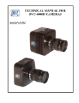
Baumer TXG
User's Guide for Gigabit Ethernet Cameras
Document Version: v4.7
Release: 11.11.2014
Document Number: 11037655
2
Table of Contents
1.Portfolio��������������������������������������������������������������������������������������������������������������������� 6
1.1 Standard Cameras�������������������������������������������������������������������������������������������������� 7
1.2 Standard Cameras with Power over Ethernet (PoE)���������������������������������������������� 8
1.3 Standard Cameras with 3 In- and 3 Outputs����������������������������������������������������������� 9
1.4 IP67 Cameras������������������������������������������������������������������������������������������������������� 10
1.4.1 Protective Caps�����������������������������������������������������������������������������������������������11
1.4.2 Maximal Objective Length inside Protective Cap��������������������������������������������11
1.4.3 Determination of the Required Tube Length�������������������������������������������������� 12
2. Product Specifications������������������������������������������������������������������������������������������ 16
2.1 Spectral Sensitivity for Baumer TXG Cameras����������������������������������������������������� 16
2.2 Field of View Position�������������������������������������������������������������������������������������������� 19
2.2.1 Standard Cameras����������������������������������������������������������������������������������������� 19
2.2.2 Cameras with IP67 Housing��������������������������������������������������������������������������� 20
2.3 Process- and Data Interfaces������������������������������������������������������������������������������� 21
2.3.1 Interfaces of Camera Types��������������������������������������������������������������������������� 21
2.3.2 Pin-Assignment���������������������������������������������������������������������������������������������� 21
2.3.3 LEDs of Camera Types���������������������������������������������������������������������������������� 23
2.4 Acquisition Modes and Timings����������������������������������������������������������������������������� 23
2.4.1 Free Running Mode���������������������������������������������������������������������������������������� 24
2.4.2 Fixed-Frame-Rate Mode�������������������������������������������������������������������������������� 24
2.4.3 Trigger Mode�������������������������������������������������������������������������������������������������� 25
2.4.4 Advanced Timings for GigE Vision® Message Channel���������������������������������� 29
2.5 Environmental Requirements�������������������������������������������������������������������������������� 31
2.5.1 Temperature and Humidity Range������������������������������������������������������������������ 31
2.5.2 Heat Transmission������������������������������������������������������������������������������������������ 31
3. Software������������������������������������������������������������������������������������������������������������������ 32
3.1 Baumer GAPI�������������������������������������������������������������������������������������������������������� 32
3.2 3rd Party Software�������������������������������������������������������������������������������������������������� 32
4. Camera Functionalities������������������������������������������������������������������������������������������ 33
4.1 Image Acquisition�������������������������������������������������������������������������������������������������� 33
4.1.1 Image Format������������������������������������������������������������������������������������������������� 33
4.1.2 Pixel Format��������������������������������������������������������������������������������������������������� 34
4.1.3 Exposure Time����������������������������������������������������������������������������������������������� 37
4.1.4 Look-Up-Table������������������������������������������������������������������������������������������������ 38
4.1.5 Gamma Correction����������������������������������������������������������������������������������������� 38
4.1.6 Region of Interest (ROI)��������������������������������������������������������������������������������� 39
4.1.7 Binning����������������������������������������������������������������������������������������������������������� 40
4.1.8 Brightness Correction (Binning Correction)���������������������������������������������������� 41
4.1.9 Fast Mode������������������������������������������������������������������������������������������������������ 41
4.1.10 HQ Mode������������������������������������������������������������������������������������������������������ 41
4.2 Color Processing��������������������������������������������������������������������������������������������������� 42
4.3 Color Adjustment – White Balance����������������������������������������������������������������������� 42
4.3.1 User-specific Color Adjustment���������������������������������������������������������������������� 42
4.3.2 One Push White Balance������������������������������������������������������������������������������� 43
3
4.4 Analog Controls����������������������������������������������������������������������������������������������������� 43
4.4.1 Offset / Black Level����������������������������������������������������������������������������������������� 43
4.4.2 Gain���������������������������������������������������������������������������������������������������������������� 44
4.5 Pixel Correction����������������������������������������������������������������������������������������������������� 44
4.5.1 General information���������������������������������������������������������������������������������������� 44
4.5.2 Correction Algorithm��������������������������������������������������������������������������������������� 45
4.5.3 Defectpixellist������������������������������������������������������������������������������������������������� 45
4.6 Process Interface�������������������������������������������������������������������������������������������������� 46
4.6.1 Digital IOs������������������������������������������������������������������������������������������������������� 46
4.6.2 IO Circuits������������������������������������������������������������������������������������������������������� 48
4.6.3 Trigger������������������������������������������������������������������������������������������������������������ 49
4.6.4 Trigger Source������������������������������������������������������������������������������������������������ 49
4.6.5 Debouncer������������������������������������������������������������������������������������������������������ 50
4.6.6 Flash Signal���������������������������������������������������������������������������������������������������� 50
4.6.7 Timers������������������������������������������������������������������������������������������������������������� 51
4.6.8 Frame Counter����������������������������������������������������������������������������������������������� 52
4.7 Sequencer������������������������������������������������������������������������������������������������������������� 53
4.7.1 General Information���������������������������������������������������������������������������������������� 53
4.7.2 Baumer Optronic Sequencer in Camera xml-file�������������������������������������������� 54
4.7.3 Sequencer Modes������������������������������������������������������������������������������������������ 54
4.7.4 Modality���������������������������������������������������������������������������������������������������������� 54
4.7.5 Examples�������������������������������������������������������������������������������������������������������� 55
4.7.6 Capability Characteristics of Baumer-GAPI Sequencer Module�������������������� 55
4.7.7 Double Shutter����������������������������������������������������������������������������������������������� 56
4.8 User Sets�������������������������������������������������������������������������������������������������������������� 57
4.9 Factory Settings���������������������������������������������������������������������������������������������������� 57
4.10 Timestamp���������������������������������������������������������������������������������������������������������� 57
5. Interface Functionalities���������������������������������������������������������������������������������������� 58
5.1 Device Information������������������������������������������������������������������������������������������������ 58
5.2 Packet Size and Maximum Transmission Unit (MTU)������������������������������������������� 58
5.3 Inter Packet Gap��������������������������������������������������������������������������������������������������� 58
5.3.1 Example 1: Multi Camera Operation – Minimal IPG��������������������������������������� 59
5.3.2 Example 2: Multi Camera Operation – Optimal IPG��������������������������������������� 59
5.4 Transmission Delay����������������������������������������������������������������������������������������������� 60
5.4.1 Time Saving in Multi-Camera Operation�������������������������������������������������������� 60
5.4.2 Configuration Example����������������������������������������������������������������������������������� 61
5.5 Multicast���������������������������������������������������������������������������������������������������������������� 63
5.6 IP Configuration���������������������������������������������������������������������������������������������������� 64
5.6.1 Persistent IP��������������������������������������������������������������������������������������������������� 64
5.6.2 DHCP (Dynamic Host Configuration Protocol)����������������������������������������������� 64
5.6.3 LLA����������������������������������������������������������������������������������������������������������������� 65
5.6.4 Force IP���������������������������������������������������������������������������������������������������������� 65
5.7 Packet Resend������������������������������������������������������������������������������������������������������ 66
5.7.1 Normal Case�������������������������������������������������������������������������������������������������� 66
5.7.2 Fault 1: Lost Packet within Data Stream�������������������������������������������������������� 66
5.7.3 Fault 2: Lost Packet at the End of the Data Stream��������������������������������������� 66
5.7.4 Termination Conditions����������������������������������������������������������������������������������� 67
5.8 Message Channel������������������������������������������������������������������������������������������������� 68
5.8.1 Event Generation������������������������������������������������������������������������������������������� 68
5.9 Action Command / Trigger over Ethernet�������������������������������������������������������������� 69
5.9.1 Example: Triggering Multiple Cameras���������������������������������������������������������� 69
4
6. Start-Stop-Behaviour��������������������������������������������������������������������������������������������� 70
6.1 Start / Stop Acquisition (Camera)�������������������������������������������������������������������������� 70
6.2 Start / Stop Interface��������������������������������������������������������������������������������������������� 70
6.3 Pause / Resume Interface������������������������������������������������������������������������������������ 70
6.4 Acquisition Modes������������������������������������������������������������������������������������������������� 70
6.4.1 Free Running�������������������������������������������������������������������������������������������������� 70
6.4.2 Trigger������������������������������������������������������������������������������������������������������������ 70
6.4.3 Sequencer������������������������������������������������������������������������������������������������������ 70
7. Lens Mounting�������������������������������������������������������������������������������������������������������� 71
8. Cleaning (Cover glass/Housing)��������������������������������������������������������������������������� 71
9. Disposal������������������������������������������������������������������������������������������������������������������ 73
10.Warranty Notes������������������������������������������������������������������������������������������������������� 73
11.Transport / Storage������������������������������������������������������������������������������������������������ 73
12.Conformity�������������������������������������������������������������������������������������������������������������� 74
12.1 CE����������������������������������������������������������������������������������������������������������������������� 74
12.2 FCC – Class B Device���������������������������������������������������������������������������������������� 74
12.3 UL – Class III Device������������������������������������������������������������������������������������������� 74
13.Support�������������������������������������������������������������������������������������������������������������������� 75
5
1. Portfolio
All Baumer Gigabit Ethernet cameras of the TXG family are characterized by:
6
Best image quality
▪▪ High-quality progressive scan CCD sensors with
highest sensitivity
▪▪ Image output data in 8 / 10 / 12 bit resolution
▪▪ Low noise and structure-free image information
▪▪ High quality mode with minimum noise
Flexible image acquisition
▪▪ Exposure times from 4 μs to 60.000 ms
▪▪ Binning and true partial scan readout modes
▪▪ Industrially compliant process interface with
parameter setting capability
(trigger and flash)
Fast image transfer
▪▪ Reliable transmission at 1000 Mbit/sec according
to IEEE802.3
▪▪ Cable length up to 100 m
▪▪ Baumer driver for high data volume with low CPU
load
▪▪ High-speed multi-camera operation
▪▪ Gen<I>Cam™ and GigE Vision® compliant
Perfect integration
▪▪ Flexible generic programming interface (BaumerGAPI) for all Baumer cameras
▪▪ Powerful Software Development Kit (SDK) with
sample codes and help files for simple integration
▪▪ Baumer viewer for all camera functions
▪▪ Interface for .NET ( C#, VB.NET), C and C++
▪▪ Software for Windows® XP / Vista™ and Linux®, 32
bit and 64 bit
▪▪ Gen<I>Cam™ compliant XML file to describe the
camera functions
▪▪ Supplied with installation program with automatic
camera recognition for simple commissioning
Compact design
▪▪ Rugged, industrial housing design
▪▪ Uniform dimensions (36 mm x 36 mm frontside) for
all standard models
▪▪ Light weight
Reliable operation
▪▪ State-of-the-art camera electronics and precision
mechanics
▪▪ Low power consumption and minimal heat generation
▪▪ Long lifetime
2. Product Specifications
2.1 Spectral Sensitivity for Baumer TXG Cameras
The spectral sensitivity characteristics of monochrome and color matrix sensors for
Baumer Gigabit Ethernet cameras are displayed in the following graphs. The characteristic curves for the sensors do not take the characteristics of lenses and light sources
without filters into consideration.
Figure 12 ►
Spectral sensitivities for
Baumer cameras with
0.3 MP*) CCD sensor.
10
10
08
08
Relative Response
Relative Response
Values relating to the respective technical data sheets of SONY Corporation.
06
04
02
06
04
02
0
0
400
500
TXG02
600
700
800
900
1000
400
450
TXG02c
Wave Length [nm]
500
550
600
650
700
650
700
650
700
Wave Length [nm]
10
08
08
06
04
16
04
0
0
400
500
TXG03
600
700
800
900
1000
400
450
TXG03c
Wave Length [nm]
10
08
08
Relative Response
10
06
04
500
550
600
Wave Length [nm]
06
04
02
02
Figure 14 ►
Spectral sensitivities for
Baumer cameras with
0.3 MP CCD sensor.
06
02
02
Relative Response
Figure 13 ►
Spectral sensitivities for
Baumer cameras with
0.3 MP CCD sensor.
10
Relative Response
Relative Response
*) MP = Megapixels
0
0
400
TXG04
500
600
700
800
Wave Length [nm]
900
1000
400
TXG04c
450
500
550
600
Wave Length [nm]
10
Relative Response
08
06
04
◄ Figure 15
Spectral sensitivities for
Baumer cameras with
0.3 MP Kodak CCD
sensor.
02
0
400
500
800
900
1000
10
08
08
06
04
06
04
02
02
0
0
500
TXG06
600
700
800
900
1000
400
10
10
08
08
06
04
0
0
500
600
700
800
900
400
1000
10
08
08
Relative Response
10
06
04
0
0
500
600
700
800
Wave Length [nm]
900
1000
700
700
◄ Figure 17
Spectral sensitivities for
Baumer cameras with
0.8 MP CCD sensor.
450
500
550
600
650
Wave Length [nm]
04
02
400
650
06
02
TXG12
600
Wave Length [nm]
TXG08c
Wave Length [nm]
550
04
02
400
500
◄ Figure 16
Spectral sensitivities for
Baumer cameras with
0.6 MP CCD sensor.
06
02
TXG08
450
TXG06c
Wave Length [nm]
Relative Response
Relative Response
700
Wave Length [nm]
10
400
Relative Response
600
Relative Response
Relative Response
TXG04h
400
TXG12c
450
500
550
600
Wave Length [nm]
650
700
◄ Figure 18
Spectral sensitivities for
Baumer cameras with
1,2 MP CCD sensor.
17
10
08
08
Relative Response
Relative Response
10
06
04
0
0
400
500
700
800
900
400
1000
10
10
08
08
06
04
0
500
600
700
800
900
600
650
700
650
700
650
700
650
700
06
04
1000
400
450
TXG14c
Wave Length [nm]
10
10
08
08
Relative Response
Relative Response
TXG14
06
04
500
550
600
Wave Length [nm]
06
04
02
0
0
400
500
TXG20
600
700
800
900
1000
400
450
TXG20c
Wave Length [nm]
10
10
08
08
Relative Response
Relative Response
18
550
Wave Length [nm]
0
400
06
04
02
Figure 22 ►
Spectral sensitivities for
Baumer cameras with
5.0 MP CCD sensor.
500
02
02
Figure 21 ►
Spectral sensitivities for
Baumer cameras with
2.0 MP CCD sensor.
450
TXG13c
Wave Length [nm]
Relative Response
Relative Response
TXG13
600
02
Figure 20 ►
Spectral sensitivities for
Baumer cameras with
1.4 MP CCD sensor.
04
02
02
Figure 19 ►
Spectral sensitivities for
Baumer cameras with
1.4 MP CCD sensor.
06
500
550
600
Wave Length [nm]
06
04
02
0
0
400
TXG50
500
600
700
800
Wave Length [nm]
900
1000
400
TXG50c
450
500
550
600
Wave Length [nm]
2.4.3.2 Overlapped Operation: texposure(n+2) > texposure(n+1)
If the exposure time (texposure) is increased form the current acquisition to the next acquisition, the time the camera is unable to process occuring trigger signals (tnotready) is scaled
down.
This can be simulated with the formulas mentioned above (no. 2 or 4, as is the case).
Trigger
tmin
ttriggerdelay
Timings:
A - exposure time
frame (n) effective
B - image parameters frame (n) effective
C - exposure time
frame (n+1) effective
D - image parameters frame (n+1) effective
E - earliest possible trigger
Image parameters:
Offset
Gain
Mode
Partial Scan
26
Exposure
texposure(n)
treadout(n)
Readout
TriggerReady
Flash
texposure(n+1)
treadout(n+1)
tnotready
tflash(n)
tflashdelay
texposure(n+2)
tflash(n+1)
2.4.3.3 Overlapped Operation: texposure(n+2) < texposure(n+1)
If the exposure time (texposure) is decreased from the current acquisition to the next acquisition, the time the camera is unable to process occuring trigger signals (tnotready) is scaled
up.
When decreasing the texposure such, that tnotready exceeds the pause between two incoming
trigger signals, the camera is unable to process this trigger and the acquisition of the image will not start (the trigger will be skipped).
Trigger
tmin
ttriggerdelay
Exposure
texposure(n)
treadout(n)
Readout
TriggerReady
Flash
texposure(n+1)
texposure(n+2
treadout(n+1)
tnotready
tflash(n)
tflash(n+1)
tflashdelay
Timings:
A - exposure time
frame (n) effective
B - image parameters frame (n) effective
C - exposure time
frame (n+1) effective
D - image parameters frame (n+1) effective
E - earliest possible trigger
F - frame not started /
trigger skipped
Image parameters:
Offset
Gain
Mode
Partial Scan
Notice
From a certain frequency of the trigger signal, skipping triggers is unavoidable. In general, this frequency depends on the combination of exposure and readout times.
27
2.4.3.4 Non-overlapped Operation
If the frequency of the trigger signal is selected for long enough, so that the image acquisitions (texposure + treadout) run successively, the camera operates non-overlapped.
Trigger
tmin
ttriggerdelay
Timings:
A - exposure time
frame (n) effective
B - image parameters frame (n) effective
C - exposure time
frame (n+1) effective
D - image parameters frame (n+1) effective
E - earliest possible trigger
Image parameters:
Offset
Gain
Mode
Partial Scan
28
Exposure
texposure(n)
treadout(n)
Readout
TriggerReady
Flash
texposure(n+1)
treadout(n+1)
tnotready
tflash(n)
tflashdelay
tflash(n+1)
2.4.4 Advanced Timings for GigE Vision® Message Channel
The following charts show some timings for the event signaling by the asynchronous
message channel. Vendor-specific events like "TriggerReady", "TriggerSkipped", "TriggerOverlapped" and "ReadoutActive" are explained.
Notice
For further information on the message channel mentioned above, please see
section 5.6.
2.4.4.1 TriggerReady
This event signals whether the camera is able to process incoming trigger signals or not.
Trigger
Exposure
texposure(n)
treadout(n)
Readout
TriggerReady
texposure(n+1)
treadout(n+1)
tnotready
2.4.4.2 TriggerSkipped
If the camera is unable to process incoming trigger signals, which means the camera
should be triggered within the interval tnotready, these triggers are skipped. On Baumer
TXG cameras the user will be informed about this fact by means of the event "TriggerSkipped".
Trigger
Exposure
texposure(n)
treadout(n)
Readout
TriggerReady
texposure(n+1)
treadout(n+1)
tnotready
TriggerSkipped
29
2.4.4.3 TriggerOverlapped
This signal is active, as long as the sensor is exposed and read out at the same time.
which means the camera is operated overlapped.
Trigger
Exposure
texposure(n)
texposure(n+1)
treadout(n)
Readout
treadout(n+1)
Trigger
Overlapped
Once a valid trigger signal occures not within a readout, the "TriggerOverlapped" signal
changes to state low.
2.4.4.4 ReadoutActive
While the sensor is read out, the camera signals this by means of "ReadoutActive".
Trigger
Exposure
Readout
Readout
Active
30
texposure(n)
texposure(n+1)
treadout(n)
treadout(n+1)
3. Software
3.1 Baumer GAPI
Baumer GAPI stands for Baumer “Generic Application Programming Interface”. With this
API Baumer provides an interface for optimal integration and control of Baumer Gigabit
Ethernet (GigE) and Baumer FireWire™ (IEEE1394) cameras.
This software interface allows changing to other camera models or interfaces. It also allows the simultaneous operation of Baumer cameras with Gigabit Ethernet and FireWire™
interfaces.
This GAPI supports both Windows® (XP and Vista) and Linux® (from Kernel 2.6.x) operating systems in 32 bit, as well as in 64 bit. It provides interfaces to several programming
languages, such as C, C++ and the .NET™ Framework on Windows®, as well as Mono
on Linux® operating systems, which offers the use of other languages, such as e.g. C# or
VB.NET.
3.2 3rd Party Software
Strict compliance with the Gen<I>Cam™ standard allows Baumer to offer the use of 3rd
Party Software for operation with cameras of the TXG family.
You can find a current listing of 3rd Party Software, which was tested successfully in combination with Baumer cameras, at http://www.baumer.com/de-en/products/identificationimage-processing/software-and-starter-kits/third-party-software/
32
4.1.2 Pixel Format
On Baumer digital cameras the pixel format depends on the selected image format.
4.1.2.1 Definitions
RAW:
Raw data format. Here the data are stored without processing.
Bayer:
Raw data format of color sensors.
Color filters are placed on these sensors in a checkerboard pattern, generally
in a 50% green, 25% red and 25% blue array.
Mono:
Monochrome. The color range of mono images consists of shades of a single
color. In general, shades of gray or black-and-white are synonyms for monochrome.
RGB:
Color model, in which all detectable colors are defined by three coordinates,
Red, Green and Blue.
Figure 27 ►
Sensor with Bayer
Pattern
Red
White
Black
Figure 28 ►
RBG color space displayed as color tube.
Green
Blue
The three coordinates are displayed within the buffer in the order R, G, B.
34
BGR:
Here the color alignment mirrors RGB.
YUV:
Color model, which is used in the PAL TV standard and in image compression.
In YUV, a high bandwidth luminance signal (Y: luma information) is transmitted
together with two color difference signals with low bandwidth (U and V: chroma
information). Thereby U represents the difference between blue and luminance
(U = B - Y), V is the difference between red and luminance (V = R - Y). The third
color, green, does not need to be transmitted, its value can be calculated from
the other three values.
YUV 4:4:4
Here each of the three components has the same sample rate.
Therefore there is no subsampling here.
YUV 4:2:2
The chroma components are sampled at half the sample rate.
This reduces the necessary bandwidth to two-thirds (in relation to
4:4:4) and causes no, or low visual differences.
YUV 4:1:1
Here the chroma components are sampled at a quater of the
sample rate.This decreases the necessary bandwith by half (in
relation to 4:4:4).
4.1.4 Look-Up-Table
The Look-Up-Table (LUT) is employed on Baumer monochrome cameras. It contains 212
(4096) values for the available levels of gray. These values can be adjusted by the user.
In this example the LUT is used to overwrite levels of gray which are not of interest or in
the case of overdrive.
4.1.5 Gamma Correction
H
With this feature, Baumer TXG cameras offer the possibility of compensating nonlinearity
in the perception of light by the human eye.
For this correction, the corrected pixel intensity (Y') is calculated from the original intensity
of the sensor's pixel (Yoriginal) and correction factor γ using the following formula (in oversimplified version):
0
E
▲ Figure 34
Non-linear perception of
the human eye.
H -Perception of bright-
ness
E - Energy of light
38
γ
Y' = Yoriginal
On Baumer TXG cameras the correction factor γ is adjustable from 0.001 to 2.
The values of the calculated intensities are entered into the Look-Up-Table (see 4.1.4.).
Thereby previously existing values within the LUT will be overwritten.
Notice
If the LUT feature is disabled on the software side, the gamma correction feature also
is disabled.
5. Interface Functionalities
5.1 Device Information
This Gigabit Ethernet-specific information on the device is part of the Discovery-Acknowledge of the camera.
Included information:
▪▪ MAC address
▪▪ Current IP configuration (persistent IP / DHCP / LLA)
▪▪ Current IP parameters (IP address, subnet mask, gateway)
▪▪ Manufacturer's name
▪▪ Manufacturer-specific information
▪▪ Device version
▪▪ Serial number
▪▪ User-defined name (user programmable string)
5.2 Packet Size and Maximum Transmission Unit (MTU)
Network packets can be of different sizes. The size depends on the network components
employed. When using GigE Vision®- compliant devices, it is generally recommended
to use larger packets. On the one hand the overhead per packet is smaller, on the other
hand larger packets cause less CPU load.
The packet size of UDP packets can differ from 576 Bytes up to the MTU.
The MTU describes the maximal packet size which can be handled by all network components involved.
In principle modern network hardware supports a packet size of 1500 Byte, which is
specified in the network standard. However, so-called "Jumboframes" are on the advance
as Gigabit Ethernet continues to spread. "Jumboframes" merely characterizes a packet
size exceeding 1500 Bytes.
Baumer TXG cameras can handle a MTU of up to 65535 Bytes.
5.3 Inter Packet Gap
IPG:
The IPG is measured in
ticks (described in chapter
5.2).
An easy rule of thumb is:
1 Tick is equivalent to 4
Bytes of data.
You should also not forget
to add the various ethernet
headers to your calculation.
58
To achieve optimal results in image transfer, several Ethernet-specific factors need to be
considered when using Baumer TXG cameras.
Upon starting the image transfer of a camera, the data packets are transferred at maximum transfer speed (1 Gbit/sec). In accordance with the network standard, Baumer employs a minimal separation of 12 Bytes between two packets. This separation is called
"inter packet gap" (IPG). In addition to the minimal IPG, the GigE Vision® standard stipulates that the IPG be scalable (user-defined).
In general, the transmission delay is calculated as:
n
t TransmissionDelay( Camera n ) = t exp osure( Camera 1) + t readout ( Camera 1) − t exp osure( Camera n ) + ∑ t transferGigE( Camera n
1)
n≥3
Therewith for the example, the transmission delays of camera 2 and 3 are calculated as
follows:
tTransmissionDelay(Camera 2) = texposure(Camera 1) + treadout(Camera 1) - texposure(Camera 2)
tTransmissionDelay(Camera 3) = texposure(Camera 1) + treadout(Camera 1) - texposure(Camera 3) + ttransferGige(Camera 2)
Solving this equations leads to:
tTransmissionDelay(Camera 2) = 32 msec + 50 msec - 32 msec
= 50 msec
= 1562500 Ticks
62
tTransmissionDelay(Camera 3) = 32 msec + 50 msec - 32 msec + 2.4 msec
= 52.4 msec
= 1637500 Ticks
6. Start-Stop-Behaviour
6.1 Start / Stop Acquisition (Camera)
Once the image acquisition is started, three steps are processed within the camera:
▪▪ Determination of the current set of image parameters
▪▪ Exposure of the sensor
▪▪ Readout of the sensor.
Afterwards a repetition of this process takes place until the camera is stopped.
Stopping the acquisition means that the process mentioned above is aborted. If the stop
signal occurs within a readout, the current readout will be finished before stopping the
camera. If the stop signal arrives within an exposure, this will be aborted.
Asynchronous Reset:
For further information on
the timings of this feature,
please see the respective
data sheets.
Special Case: Asynchronous Reset
The asynchronous reset represents a special case of stopping the current acquisition.
Thereby exposure is aborted immediately. Thus the current image is not read out and the
image is upcasted.
This feature was introduced to accelerate the changing of image parameters.
6.2 Start / Stop Interface
Without starting the interface, transmission of image data from the camera to the PC
will not proceed. If the image acquisition is started befor the interface is activated, the
recorded images are lost.
If the interface is stopped during a transmission, this is aborted immediately.
6.3 Pause / Resume Interface
Pausing while the interface is operational, results in an interim storage of the recorded
images within the internal buffer of the camera.
After resuming the interface, the buffered image data will be transferred to the PC.
6.4 Acquisition Modes
In general, three acquisition modes are available for the cameras in the Baumer TXG
series.
6.4.1 Free Running
Free running means the camera records images continuously without external events.
6.4.2 Trigger
The basic idea behind the trigger mode is the synchronization of cameras with machine
cycles. Trigger mode means that image recording is not continuous, but triggered by
external events.
This feature is described in chapter 4.6. Process Interface.
6.4.3 Sequencer
A sequencer is used for the automated control of series of images, using different settings
for exposure time and gain. This feature is described in chapter 4.7.
70
12. Conformity
Cameras of the Baumer TXG family comply with:
▪▪ CE,
▪▪ FCC Part 15 Class B,
▪▪ UL,
▪▪ RoHS
12.1 CE
We declare, under our sole responsibility, that the previously described Baumer TXG
cameras conform with the directives of the CE.
12.2 FCC – Class B Device
Note: This equipment has been tested and found to comply with the limits for a Class B
digital device, pursuant to part 15 of the FCC Rules. These limits are designed to provide reasonable protection against harmful interference in a residential environment. This
equipment generates, uses, and can radiate radio frequency energy and, if not installed
and used in accordance with the instructios, may cause harmful interference to radio
communications. However, there is no guarantee that interference will not occure in a
particular installation. If this equipment does cause harmful interference to radio or television reception, which can be determined by turning the equipment off an on, the user is
encouraged to try to correct the interference by one or more of the following measures:
▪▪ Reorient or relocate the receiving antenna.
▪▪ Increase the separation between the equipment and the receiver.
▪▪ Connect the equipment into an outlet on a circuit different from that to which the
receiver is connected.
▪▪ Consult the dealer or an experienced radio/TV technician for help.
12.3 UL – Class III Device
Power supply for operation of the TXG series of cameras must be provided using a limited
power supply in accordance with UL60950.
74
13. Support
If you have any problems with the camera, then feel free to contact our support.
Worldwide
Baumer Optronic GmbH
Badstrasse 30
DE-01454 Radeberg, Germany
Tel: +49 (0)3528 4386 845
Mail: [email protected]
Website: www.baumer.com
75
Subject to change without notice. Printed in Germany 02/13.
Technical data has been fully checked, but accuracy of printed matter not guaranteed.
Baumer Optronic GmbH
Badstrasse 30
DE-01454 Radeberg, Germany
Phone +49 (0)3528 4386 0 · Fax +49 (0)3528 4386 86
[email protected] · www.baumer.com