1
FERUM 4.0 User’s Guide
J.-M. Bourinet
September 22, 2009
Abstract
c
The development of FERUM (Finite Element Reliability Using Matlab) as an open-source Matlab
toolbox
was initiated in 1999 under Armen Der Kiureghian’s leadership at the University of California at Berkeley
(UCB). This general purpose structural reliability code was developed and maintained by Terje Haukaas, with
the contributions of many researchers at UCB.
The present document aims at presenting the main features and capabilities of a new version of this
open-source code (FERUM 4.0) based on a work carried out at the Institut Français de Mécanique Avancée
(IFMA) in Clermont-Ferrand, France. This new version offers improved capabilities such as simulation-based
technique (Subset Simulation), Global Sensitivity Analysis (based on Sobol’s indices), Reliability-Based Design Optimization (RBDO) algorithm, etc. Beyond the new methods implemented in this code, an emphasis
is put on the new architecture of the code, which now allows distributed computing, either virtually through
vectorized calculations within Matlab or for real with multi-processor computers.
An important note about this User’s Guide is that it does not contain a detailed description of FERUM
usage and FERUM available methods. The user must have some prior knowledge about probability concepts,
stochastic methods, structural reliability, sensitivity analysis, etc. More details about the FERUM inputs may
be found in the template input file (template_inputfile.m) provided with the FERUM package. This document
has been mainly elaborated from FERUM 4.0 reference paper [BMD09].
The FERUM 4.0 package is available under the conditions of the GNU General Public License, like FERUM
3.1. This implies that you may download the program for free. However, if you make changes or additions
you must make them available for free under the same general public license.
1
Contents
1 Introduction
3
2 Problem definition and structure of FERUM
2.1 Time invariant structural reliability . . . . . . . . . . . . . . . . . . . . . .
2.2 Probability distributions and transformation to standard normal space
2.3 Definition of limit-state functions . . . . . . . . . . . . . . . . . . . . . . .
2.4 Vectorized / distributed computing . . . . . . . . . . . . . . . . . . . . . .
.
.
.
.
.
.
.
.
.
.
.
.
.
.
.
.
.
.
.
.
.
.
.
.
.
.
.
.
.
.
.
.
.
.
.
.
.
.
.
.
.
.
.
.
.
.
.
.
.
.
.
.
.
.
.
.
.
.
.
.
.
.
.
.
3
3
4
5
6
3 Overview of available methods
3.1 FORM and reliability sensitivities / importance measures
3.1.1 Basic FORM . . . . . . . . . . . . . . . . . . . . . . . .
3.1.2 Reliability sensitivities / importance measures . . .
3.1.3 FORM with search for multiple design points . . .
3.2 SORM curvature-fitting and point-fitting . . . . . . . . . . .
3.3 Distribution Analysis . . . . . . . . . . . . . . . . . . . . . . .
3.4 Crude Monte Carlo Simulation, Importance Sampling . . .
3.5 Directional Simulation . . . . . . . . . . . . . . . . . . . . . .
3.6 Subset Simulation . . . . . . . . . . . . . . . . . . . . . . . . .
3.7 Global Sensitivity Analysis . . . . . . . . . . . . . . . . . . . .
3.8 Reliability-Based Design Optimization . . . . . . . . . . . .
3.9 Random fields . . . . . . . . . . . . . . . . . . . . . . . . . . .
.
.
.
.
.
.
.
.
.
.
.
.
.
.
.
.
.
.
.
.
.
.
.
.
.
.
.
.
.
.
.
.
.
.
.
.
.
.
.
.
.
.
.
.
.
.
.
.
.
.
.
.
.
.
.
.
.
.
.
.
.
.
.
.
.
.
.
.
.
.
.
.
.
.
.
.
.
.
.
.
.
.
.
.
.
.
.
.
.
.
.
.
.
.
.
.
.
.
.
.
.
.
.
.
.
.
.
.
.
.
.
.
.
.
.
.
.
.
.
.
.
.
.
.
.
.
.
.
.
.
.
.
.
.
.
.
.
.
.
.
.
.
.
.
.
.
.
.
.
.
.
.
.
.
.
.
.
.
.
.
.
.
.
.
.
.
.
.
.
.
.
.
.
.
.
.
.
.
.
.
.
.
.
.
.
.
.
.
.
.
.
.
6
6
6
7
8
8
9
9
11
12
13
15
16
.
.
.
.
.
.
.
.
.
.
.
.
.
.
.
.
.
.
.
.
.
.
.
.
.
.
.
.
.
.
.
.
.
.
.
.
.
.
.
.
.
.
.
.
.
.
.
.
.
.
.
.
.
.
.
.
.
.
.
.
.
.
.
.
.
.
.
.
.
.
.
.
.
.
.
.
.
.
.
.
.
.
.
.
.
.
.
.
.
.
.
.
.
.
.
.
4 Getting started
16
5 Organization of FERUM 4.0 m-files
16
2
1 Introduction
FERUM (Finite Element Reliability Using Matlab) is a general purpose structural reliability code whose first
developments started in 1999 at the University of Cafifornia at Berkeley (UCB) [DKHF06]. This code consists
c
of an open-source Matlab
toolbox, featuring various structural reliability methods. As opposed to commercial structural reliability codes, see e.g. [PS06] for a review in 2006, the main objective of FERUM is to provide
students with a tool immediately comprehensible and easy to use and researchers with a tool very accessible
which they may develop for research purposes. The scripting language of Matlab is perfect for such objectives,
as it allows users to give commands in a very flexible way, either in an interactive mode or in a batch mode
through input files.
FERUM was created under Prof. Armen Der Kiureghian’s leadership and was managed by Terje Haukaas at
UCB until 2003. It benefited from a prior experience with CalRel structural reliability code, which features all
the methods implemented in the last version of FERUM. It also benefited from the works of many researchers
at UCB, who made valuable contributions in the latest available version (version 3.1), which can be downloaded at the following address: http://www.ce.berkeley.edu/FERUM/. Since 2003, this code is no longer
officially maintained.
This document is a draft user’s manual of a new version of this code (FERUM 4.0), which results from
a work carried out at the Institut Français de Mécanique Avancée (IFMA) in Clermont-Ferrand. As previously
achieved in the past, the main intention is to provide students and researchers with a developer-friendly computational platform which facilitates learning methods and serves as a basis for collaborative research works.
FERUM should still be viewed as a development platform for testing new methods and applying them to
various challenging engineering problems, either represented by basic analytical models or more elaborated
numerical models, through proper user-defined interfaces.
The main architecture of FERUM was preserved in general, see Section 2 for more details. In order to
improve its efficiency in terms of computational time, all algorithms have been revisited to extend FERUM
capabilities to distributed computing. For example, in its new version, FERUM makes Monte Carlo Simulation
(MCS) much faster thanks to limit-state functions defined in a vectorized form or real distributed computing,
according that a proper interface is defined for sending multiple jobs to a multi-processor computer platform.
2 Problem definition and structure of FERUM
This section briefly presents the general formulation of time-invariant structural reliability problems. In addition to some very brief details about theoretical concepts, this section highlights how these concepts are
translated to FERUM structure. This includes for instance the stochastic model, the transformation to standard normal variates, limit-state functions and more generally other points regarding computational aspects.
It is important here to recall that the main structure of input data in FERUM is preserved compared to version
3.1 (same Matlab structure variables: probdata, analysisopt, gfundata, femodel). Changes brought
to FERUM are applied to core m-functions and within the fields of the existing structure variables. Similarly
to version 3.1, results are stored in structure variables with the following syntax: results keyword appended
to the name of the method applied, such as e.g. formresults, sormcfhresults, etc.
2.1 Time invariant structural reliability
We consider here only time invariant structural reliability problems, see e.g. [DM07, Lem09]. The probability
w.r.t. an undesired or unsafe state is expressed in terms of a n-dimensional vector X of random variables with
continuous joint density function fX (x, θ f ), where θ f stands for a vector of distribution parameters. Failure
is defined in terms of a limit-state function g(x, θ g ) where x is a realization of the random vector X and θ g
denotes a vector of deterministic limit-state function parameters. We restrict here the analysis to component
reliability with a single g function, but this function may represent multiple failure modes in subset simulation
in Section 3.6, without lack of generality. This limit-state function divides the random variable space in a safety
domain, g(x, θ g ) > 0, and a failure domain, g(x, θ g ) ≤ 0. The probability of failure therefore reads:
Z
pf =
fX (x, θ f ) dx
g(x,θ g )≤0
3
(1)
2.2 Probability distributions and transformation to standard normal space
The joint density function fX (x, θ f ) is often unknown and replaced by its Nataf counterpart completely
defined by specifying marginal distributions and the Gaussian correlation structure between random variables, see [LDK86]. This Nataf joint distribution is completely specified by variables probdata.marg and
probdata.correlation in FERUM input files. FERUM has a rich library of probability distribution models, including extreme value distributions and a truncated normal distribution. These distributions can be
specified through either their statistical moments or parameters. See hereafter the corresponding part of the
inputfile_template.m file.
%
%
%
%
%
%
%
%
%
%
%
%
%
%
%
%
%
%
%
%
%
%
%
%
%
%
%
%
%
%
%
%
%
%
%
%
%
%
%
%
%
%
%
%
%
%
%
%
%
%
%
%
%
Marginal distributions for each random variable
probdata.marg = [ (type) (mean) (stdv) (startpoint) (p1) (p2) (p3) (p4) (input_type); ... ];
type: -1 = Parameter in reliability analysis (thetag)
0 = Deterministic parameter (cg)
1
2
3
4
5
6
7
8
=
=
=
=
=
=
=
=
Normal distribution
Lognormal distribution
Gamma distribution
Shifted exponential distribution
Shifted Rayleigh distribution
Uniform distribution
Beta distribution
Chi-square distribution
11
12
13
14
15
16
=
=
=
=
=
=
Type I largest value distribution ( same as Gumbel distribution )
Type I smallest value distribution
Type II largest value distribution
Type III smallest value distribution
Gumbel distribution ( same as type I largest value distribution )
Weibull distribution ( same as Type III smallest value distribution with epsilon = 0 )
18
19
(Reserved for Laplace distribution)
(Reserved for Pareto distribution)
51 = Truncated normal marginal distribution
Notes:
- Each field type, mean, stdv, startpoint, p1, p2, p3, p4, input_type must be filled in.
If not used, input a dummy nan value.
- input_type = 0 when distributions are defined with mean and stdv only
1 when distributions are defined with distribution parameters pi
(i = 1, 2, 3 or 4, depending on the total number of parameters required)
- For the Type III smallest value marginal distribution, you must give the value of
epsilon parameter as p3 when using the mean and stdv input (input_type = 0).
- For the Beta marginal distribution , you must give the value of a parameter as p3 and
b parameter as p4 when using the mean and stdv input (input_type = 0).
- For the Truncated normal marginal distribution, you must set input_type = 1 and give :
* the mean and stdv of the untruncated marginal distribution as p1 and p2 respectively
* the lower bound xmin and the upper bound xmax as p3 and p4 respectively
- startpoint stands for the starting point of the FORM analysis in the physical space
- Refer to ferum_pdf.m, ferum_cdf.m and distribution_parameter.m functions for more information
on a specific distribution.
Correlation matrix
This matrix is a square matrix with dimension equal to size(probdata.marg,1).
Lines/columns corresponding to parameters in reliability analysis(thetag) or deterministic
parameters (cg) are removed in a pre-processing stage of FERUM, by means of the update_data.m
function.
The structural reliability problem of Equation (1) expressed in the original space of physical random variables X is transformed to a standard normal space where U becomes an independent standard normal vector.
This mapping is carried out in FERUM using the Nataf model [LDK86]. Physical random variables X are
transformed to correlated standard normal variables Z whose correlation structure obeys integral relation of
Equation (3) and Z is then transformed to uncorrelated standard normal variables U.
f , i = 1, . . . , n
X
X with i
7→ Z ∼ N 0, R0
7→ U ∼ N (0, I)
(2)
R
=
ρ
i j n×n
4
For each i j-pair of variables with known correlation ρi j , Equation (3) should be solved to determine
correlation ρ0 i j between mapped z-variables:
Z +∞ Z +∞
x j − µj
x i − µi
ρi j =
ϕ2 (zi , z j , ρ0 i j ) dzi dz j
(3)
σi
σj
−∞
−∞
where µi and σi respectively stand for the mean and standard deviation of the ith component of X, and
ϕ2 (•, •, ρ) is the 2D standard normal probability density function (pdf) with correlation coefficient ρ.
Independent standard normal variables U are then obtained from Z variables such as follows:
u = L−1
0 z
(4)
where L0 is the lower-triangular Cholesky decomposition of R0 = ρ0 i j matrix, such that L0 LT0 = R0 .
Solutions of Equation (3) can be found by formulae of reference [LDK86] for most common statistical
distributions. These formulae are most often obtained by least-square fitting and therefore approximate, except for a few pairs of distributions. FERUM 4.0 is now based on accurate solutions obtained by 2D numerical
Gauss integration of Equation (3). A particular attention is paid to strongly correlated random variables,
where the number of integration points along each dimension in zi z j -space must be selected carefully, for
accurate ρ0 i j values. A practical rule adopted here consists in increasing these numbers of points with correlation, ranging from 32 points along each dimension for absolute values of correlation lower than 0.9 to 1024
points for absolute values larger than 0.9995.
2.3 Definition of limit-state functions
As in FERUM 3.1, the limit-state function is defined through the structure variable gfundata of the input file
and called by the file named gfun.m. Various strategies are now offered in FERUM 4.0. The limit-state function can either be a simple expression directly written in the input file or a Matlab function. For both cases,
gfun.m calls another function called gfunbasic.m. Another interesting option offered in FERUM 4.0 is that the
limit-state function can be defined through a user-provided Matlab function, which calls a third-party software, such as a Finite Element code. Such merging of FERUM with problem-specific external codes was made
in various applications, such as probabilistic buckling [DNBF09] and crack propagation [NBGL06]. For controlling such external codes, extra variables are provided to FERUM through the structure variable femodel
and the user must create an application-specific function. One more option available in FERUM 4.0 is that it
takes advantage of gradients w.r.t. all or parts of the basic variables, when available from the external code.
This proves to be very useful when limit-state functions involve very computationally demanding numerical
c
models, as it avoids tedious estimations by finite differences. FERUM 4.0 is compatible with Code_Aster
,
running on a Windows OS. Code_Aster version STA9.1 compiled on Windows was developed by NECS and is
available at http://www.necs.fr/gb/telechargement.php.
See hereafter the corresponding part of the inputfile_template.m file.
% Type of limit-state function evaluator:
% ’basic’: the limit-state function is defined by means of an analytical expression or a Matlab
%
m-function, using gfundata(lsf).expression. The function gfun.m calls gfunbasic.m,
%
which evaluates gfundata(lsf).expression.
% ’xxx’:
the limit-state function evaluation requires a call to an external code. The function
%
gfun.m calls gfunxxx.m, which evaluates gfundata(lsf).expression where gext variable is
%
a result of the external code.
Case of a limit-state function which is defined by means of an analytical expression / a Matlab m-function:
gfundata(1).evaluator
gfundata(1).type
= ’basic’;
= ’expression’;
% Do no change this field!
% Expression of the limit-state function:
gfundata(1).expression = ’c1 - X2./(1000*X3) - (X1./(200*X3)).^2 - X5./(1000*X6) - (X4./(200*X6)).^2’;
% Expression of the limit-state function:
gfundata(1).expression = ’gfun_nl_oscillator(mp,ms,kp,ks,zetap,zetas,Fs,S0)’;
Case of a limit-state function which requires a call to Code_Aster FE code:
gfundata(1).evaluator
gfundata(1).type
= ’aster’;
= ’expression’;
% Do no change this field!
% Expression of the limit-state function:
gfundata(1).expression = ’gext-u0’;
5
2.4 Vectorized / distributed computing
A major change brought to FERUM 4.0 is that calls to the limit-state function g can be evaluated in a distributive manner, as opposed to the sequential manner of the previous version. Every algorithm implemented in
FERUM was revisited, so as to send multiple calls to g, whenever possible. If one thinks of FE-based Monte
Carlo Simulation (MCS) on a multiprocessor computer, the strategy consists in sending calls to the FE code
in batches, the number of jobs in each batch being equal to the number of available CPUs. This strategy is
known as distributed computing, see e.g. examples of applications in [NBGL06, DNBF09]. The number of jobs
sent simultaneously is tuned through the variable analysisopt.block_size. Such an option is available
in FERUM, assuming that the user has a suitable computer platform and all the necessary tools to create, send
and post-process multiple jobs (scripting language such as Perl, queuing systems such as OpenPBS on Linux,
job schedulers, . . . ). The function in charge of the job allocation is obviously application-specific and is called
by gfun.m.
analysisopt.multi_proc = 1;
% 1: block_size g-calls sent simultaneously
%
- gfunbasic.m is used and a vectorized version of
%
gfundata.expression is available.
%
The number of g-calls sent simultaneously (block_size) depends
%
on the memory available on the computer running FERUM.
%
- gfunxxx.m user-specific g-function is used and able to handle
%
block_size computations sent simultaneously, on a cluster
%
of PCs or any other multiprocessor computer platform.
% 0: g-calls sent sequentially
analysisopt.block_size = 50;
% Number of g-calls to be sent simultaneously
Based on the same developments of FERUM algorithms, it is also possible to send multiple calls to a userdefined Matlab limit-state function written in a vectorized manner. Vectorized calculations, in the Matlab
sense, eliminate the need to cycle through nested loops and thus run much faster because of the way Matlab
handles vectors internally. The principle is similar to distributed computing, the difference being that the
multiprocessor computer is virtually replaced by a single computer which can handle a number of runs simultaneously (this maximum number being directly dependent on the memory available on the computer). Here
again, the maximum number of runs sent simultaneously is controlled through analysisopt.block_size
variable.
For illustration purpose, on an Intel T7800 2.6GHz dual core CPU with 4Gb RAM, a crude MCS takes
31 min with 1.5 · 109 samples for a basic g = r − s problem, where R and S are normal random variables, in a
vectorized manner (FERUM 4.0), as opposed to 6 days 15 hours in a sequential manner.
3 Overview of available methods
3.1 FORM and reliability sensitivities / importance measures
3.1.1
Basic FORM
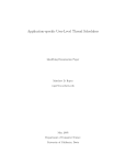
First-Order Reliability Method (FORM) (option 10 of FERUM 4.0) aims at using a first-order approximation
of the limit-state function in the standard space at the so-called Most Probable Point (MPP) of failure P* (or
design point), which is the limit-state surface closest point to the origin. Finding the coordinates u* of the
MPP consists in solving the following constrained optimization problem:
ª
§
(5)
u* = arg min kuk g(x (u) , θ g ) = G u, θ g = 0
Once the MPP P* is obtained,
the Hasofer and Lind reliability index β is computed as β = αT u* where
α = −∇u G (u*) / ∇u G (u*) is the negative normalized gradient vector at the MPP P*. It represents the
distance from the origin to the MPP in the standard space. The first-order approximation of the failure
probability is then given by p f 1 = Φ(−β), where Φ(•) is the standard normal cdf. As in FERUM 3.1, the
new version is based on the iHLRF algorithm, see [ZDK94] for further details. In order to take advantage of
distributed computing, g-calls required for gradient evaluations by finite differences at a specific point of the
standard space are sent in a single batch. The same technique is applied to step size evaluation with Armijo
rule, where all corresponding g-calls are sent simultaneously.
6
u2
ϕ 2 ( u ) = cst
1 (u) ≤ 0
G
β
u2*
O
α
P*
u1
*
1
u
G (u) = 0
1 ( u ) = β − αT u = 0
G
Figure 1: First-Order Reliability Method (FORM).
Parameters specific to FORM in the analysisopt.block_size structure variable are listed hereafter.
% FORM analysis options
analysisopt.i_max
= 100;
analysisopt.e1
= 0.001;
analysisopt.e2
= 0.001;
analysisopt.step_code
= 0;
analysisopt.Recorded_u = 1;
analysisopt.Recorded_x = 1;
% FORM, SORM analysis options
analysisopt.grad_flag = ’ddm’;
analysisopt.ffdpara
3.1.2
= 1000;
%
%
%
%
%
%
%
%
%
%
Maximum number of iterations allowed in the search algorithm
Tolerance on how close design point is to limit-state surface
Tolerance on how accurately the gradient points towards
the origin
0: step size by Armijo rule
otherwise: given value is the step size
0: u-vector not recorded at all iterations
1: u-vector recorded at all iterations
0: x-vector not recorded at all iterations
1: x-vector recorded at all iterations
%
%
%
%
%
%
’ddm’: direct differentiation
’ffd’: forward finite difference
Parameter for computation of FFD estimates of gradients
Perturbation = stdv/analysisopt.ffdpara;
Recommended values: 1000 for basic limit-state functions,
50 for FE-based limit-state functions
Reliability sensitivities / importance measures
In addition to the reliability index β and the MPP coordinates coming from a FORM analysis, the user may
use FERUM 4.0 to calculate the sensitivities of β (or of the failure probability p f ) to distribution parameters
θ f or to deterministic limit-state function parameters θ g .
For instance, the sensitivity of β w.r.t. θ f reads:
where Ju*,θ f x*, θ f
= ∂ ui /∂ θ f
j
.
T
∇θ f β = Ju*,θ f x*, θ f α
(6)
The Jacobian of the transformation is obtained by differentiating Equation (4) w.r.t. θ f parameters:
∂u
∂ θf
= L−1
0
∂z
∂ θf
+
∂ L−1
0
∂ θf
z
(7)
In FERUM 4.0, sensitivities w.r.t. distributions parameters θ f are evaluated based on both terms of Equation (7), as opposed to FERUM 3.1 which only uses the first term. Sensitivities to correlation are based on the
second term of this expression only, as the first one vanishes [BL08]. Sensitivities are evaluated numerically
with the same integration scheme as the one used for obtaining R0 matrix and it is required to differentiate the
Cholesky decomposition algorithm in a step-by-step manner. Examples of application are given in reference
[BL08].
Parameters specific to FORM reliability sensitivities are listed hereafter. Thet are set up in the probdata
structure variable for sensitivities w.r.t. distributions parameters θ f and in the gfundata structure variable
for sensitivities w.r.t. deterministic limit-state function parameters θ g .
7
% Flag for computation of sensitivities w.r.t. means, standard deviations, parameters and
% correlation coefficients
% 1: all sensitivities assessed, 0: no sensitivities assessment
probdata.flag_sens
= 1;
% Flag for computation of sensitivities w.r.t. thetag parameters of the limit-state function
% 1: all sensitivities assessed, 0: no sensitivities assessment
gfundata(1).flag_sens = 1;
analysisopt.ffdpara_thetag = 1000;
3.1.3
% Parameter for computation of FFD estimates of dbeta_dthetag
% perturbation = thetag/analysisopt.ffdpara_thetag if thetag ~= 0
%
or 1/analysisopt.ffdpara_thetag if thetag == 0
% Recommended values: 1000 for basic limit-state functions
%
100 for FE-based limit-state functions
FORM with search for multiple design points
Search for multiple MPPs such as described in [DKD98] is also implemented in FERUM 4.0 (option 11). Figure
2 illustrates the use of this method, applied to a 2D example with a parabolic limit-state function [DKD98]:
g(x) = g(x 1 , x 2 ) = b − x 2 − κ(x 1 − e)2
(8)
where b = 5, κ = 0.5 and e = 0.1. Both variables x 1 and x 2 are independent and identically distributed (i.i.d.)
standard normal random variables.
This problem is characterized by two MPPs at similar distances from the origin and basic FORM algorithm results are therefore not valid: 1.83 · 10−3 instead of 3.02 · 10−3 reference value for p f . Results in Figure
2 are obtained with parameter values recommended in [DKD98], i.e. γ = 1.1, δ = 0.75 and ε = 0.5. These
parameters are set in the form_multiple_dspts.m function. All valid MPP results obtained with FERUM 4.0 are
stored in an ALLformresults array which is added as an extra field to the analysisopt structure variable.
U-space
U-space
0
x1
5
5
x2
0
-5
-5
U-space
5
x2
x2
5
0
-5
-5
0
x1
5
0
-5
-5
0
x1
5
Figure 2: FORM with search for multiple design points.
3.2 SORM curvature-fitting and point-fitting
As in the previous version, FERUM 4.0 offers two ways for computing a second-order approximation of the
failure probability. In both methods, the SORM approximation of the failure probability p f 2 is computed with
Breitung or Tvedt formulae, as in FERUM 3.1.
The first method consists in determining the principal curvatures and directions, by solving an eigenproblem involving the Hessian of the limit-state function (option 12 of FERUM 4.0). The Hessian is computed
by finite differences, the perturbations being set in the standard normal space. All calls to the limit-state function corresponding to perturbated points are potentially sent simultaneously, as being all independent from
each other.
The second method consists in approximating the limit-state function by a piece-wise paraboloid surface [DKLH87] (option 13 of FERUM 4.0). This approximate surface must be tangent to the limit-state at
the design point and coincides with the limit-state at two points on each axis selected on both sides of the
origin, see Figure 4. It is built iteratively, with a limited number of iterations and all calls to the limit-state
function, at each iteration, are potentially sent simultaneously as well. This second approach is advantageous
for slightly-noisy limit-state functions (e.g. when a FE code is involved), for problem with a large number of
random variables or when the computation of curvatures turns out to be problematic.
8
u2 G 2 ( u ) = 0
ϕ 2 ( u ) = cst
2 (u) ≤ 0
G
u2*
O
β
P*
u1
α
*
1
u
G (u) = 0
1 ( u ) = β − αT u = 0
G
Figure 3: Second-Order Reliability Method (SORM).
un′
( v′ , v′ )
−
i
−
n
G ′ ( u′ ) = 0
β
−k β
( v′ , v′ )
+
i
kβ
+
n
ui′
Figure 4: Second-Order Reliability Method - Point-fitting method (SORM-pf).
3.3 Distribution Analysis
FERUM 4.0 offers a way to assess qualitatively (visual inspection of histograms) and quantitatively to some
extent (only mean and variance in the current version) the distribution of the random variable which corresponds to the limit-state function g (option 20 of FERUM 4.0). The limit-state function may either return a
scalar value if gfundata(lsf).ng field is set to 1 in the input file or multiple values if gfundata(lsf).ng
is set to a value strictly greater than 1 (please refer to the gfun.m function for more details).
Parameters specific to a distribution analysis are listed hereafter.
% Simulation analysis (MC,IS,DS,SS) and distribution analysis options
analysisopt.num_sim
= 1e4;
% Number of samples
analysisopt.rand_generator
= 1;
% 0: default rand matlab function
% 1: Mersenne Twister (to be preferred)
% Simulation analysis (MC, IS) and distribution analysis options
analysisopt.sim_point
= ’origin’; % ’dspt’: design point
% ’origin’: origin in standard normal space
analysisopt.stdv_sim
= 1;
% Standard deviation of sampling distribution
% in the simulation analysis
3.4 Crude Monte Carlo Simulation, Importance Sampling
Equation (1) is rewritten as follows:
pf =
Z
I (x) fX (x) dx = E fX [I (X)]
(9)
D fX
where D fX represents the integration domain of joint pdf fX (x), I (•) is an indicator function which equals 1 if
g(x) ≤ 0 and 0 otherwise, and E fX [•] denotes the mathematical expectation w.r.t. joint pdf fX (x) (θ f and θ g
parameters omitted for the sake of clarity).
9
The expectation in Equation (9) is estimated in a statistical sense for a crude Monte Carlo Simulation
(crude MCS). The u-space is randomly sampled with N independent samples u( j) , j = 1, . . . , N . These N samples are then transformed to the x-space x( j) = x(u( j) ) and an unbiased estimate of p f is finally obtained from
the sample mean of q j = I(x( j) ). Note that a standard deviation is also obtained for this sample, providing
useful information regarding the accuracy of the estimated value of p f .
It must be stressed out here that a crude MCS requires a high computational effort (large N ) for small
failure probabilities and a number of variance reduction techniques have been proposed in the past to lower
this computational effort. One of these variance reduction techniques is known as Importance Sampling (IS).
Equation (9) is rewritten now in the following form:
Z
fX (x)
fX (X)
pf =
(10)
I (x)
h(x) dx = Eh I (X)
h(x)
h(X)
D
h
where h is called a sampling density. For an IS analysis, it is usual to take h(x) = h(x(u)) = ϕn (u − u*) where
ϕn is the n-dimensional standard normal pdf and u* is the vector of MPP coordinates coming from a previous
FORM analysis. Note that p f is now obtained from the sample mean of q j = I(x( j) ) fX (x( j) ) / h(x( j) ).
X-space
X-space
10
5
5
s
s
10
0
0
0
10
-5
-10
20
0
r
(a)
(b)
5
5
0
0
-5
-5
10
r
s
s
-5
-10
0
r
(c)
-5
-5
5
0
r
(d)
20
5
Figure 5: Crude Monte Carlo (CMC) vs. Importance Sampling (IS).
FERUM 4.0 features both methods and calls to the limit-state function are sent in a distributed manner,
the maximum number of jobs sent being adjusted by the variable analysisopt.block_size. For a crude
MCS analysis in FERUM 4.0, set analysisopt.sim_point to ’origin’ and select option 21. For an IS
analysis, set analysisopt.sim_point to ’dspt’ and select option 21.
Parameters specific to a crude MCS / IS analysis are listed hereafter.
% Simulation analysis (MC,IS,DS,SS) and distribution analysis options
analysisopt.num_sim
= 1e4;
% Number of samples
analysisopt.rand_generator
= 1;
% 0: default rand matlab function
% 1: Mersenne Twister (to be preferred)
% Simulation analysis (MC, IS) and distribution analysis options
analysisopt.sim_point
= ’origin’; % ’dspt’: design point
% ’origin’: origin in standard normal space
analysisopt.stdv_sim
= 1;
% Standard deviation of sampling distribution
% in the simulation analysis
10
% Simulation analysis (MC, IS)
analysisopt.target_cov
analysisopt.lowRAM
= 0.05;
= 0;
% Target coef. of variation for failure probability
% 1: memory savings allowed
% 0: no memory savings allowed
3.5 Directional Simulation
The n-dimensional normal vector U is expressed as U = RA, R ≥ 0, where R2 is a chi-square distributed
random variable with n degrees of freedom (d.o.f.), independent of the random unit vector A, which is uniformly distributed on the n-dimensional unit sphere Ωn . The failure probability p f can be written as follows,
conditioning on A = a [Bje88]:
Z
P [G (RA) ≤ 0 | A = a ] fA (a) da
pf =
(11)
a∈Ωn
where fA (a) is the uniform density of A on the unit sphere.
Practically, a sequence of N random direction vectors a( j) = u( j) / u( j) , j = 1, . . . , N , is generated first,
then r j = { r | G(ra( j) ) = 0 } are found iteratively and p f is finally estimated from the following expression:
pf =
N h
1X
N
j=1
i
1 − χn2 r 2j
(12)
where χn2 is the chi-square cdf with n d.o.f..
u2
a(1)
a(3)
u1
O
Ω
a(2)
2
G (u) = 0
Figure 6: Directional Simulation (DS): Uniform distribution on the 2D unit sphere
u2
rj
a( j )
u1
O
Ω2
G (u) = 0
Figure 7: Directional Simulation (DS): Determination of r j radius
In FERUM 4.0, the user must select option 22 for a Directional Simulation (DS) analysis. Beside a classical
random generation of directions (analysisopt.dir_flag set to ’random’), a slightly modified version
of this algorithm is proposed. Instead of generating random directions on the unit sphere, it is proposed to
divide it into N evenly distributed points, in a deterministic manner, in order to gain an improved accuracy
at a given computational cost. This second option is selected by setting analysisopt.dir_flag to ’det’.
In the two methods, intersections with the limit-state function along each direction are obtained in a distributive manner, based on a vectorized version of fzero.m Matlab function. The maximum number of jobs sent
is adjusted by the variable analysisopt.block_size. It is worth noting that DS looses efficiency as the
number of random variables n increases.
11
Parameters specific to a DS analysis are listed hereafter.
% Simulation analysis (MC,IS,DS,SS) and distribution analysis options
analysisopt.num_sim
= 200;
% Number of directions (DS)
analysisopt.rand_generator
= 1;
% 0: default rand matlab function
% 1: Mersenne Twister (to be preferred)
% Directional Simulation (DS) analysis options
analysisopt.dir_flag
= ’det’;
%
%
%
%
%
analysisopt.rho
= 8;
%
%
analysisopt.tolx
= 1e-5;
%
analysisopt.keep_a
= 0;
%
%
analysisopt.keep_r
= 0;
%
’det’: deterministic points uniformly distributed
on the unit hypersphere using eq_point_set.m
function
’random’: random points uniformly distributed
on the unit hypersphere
Max search radius in standard normal space for
Directional Simulation analysis
Tolerance for searching zeros of g function
Flag for storage of a-values which gives axes
along which simulations are carried out
Flag for storage of r-values for which g(r) = 0
3.6 Subset Simulation
Starting from the premise that the failure event F = { g(x, θ g ) ≤ 0 } is a rare event, S.-K. Au and J.L. Beck proposed to estimate P(F ) by means of more frequent intermediate conditional failure events {Fi }, i = 1, . . . , m
(called subsets) so that F1 ⊃ F2 ⊃ . . . ⊃ Fm = F [AB01]. The m-sequence of intermediate conditional failure
events is selected so that Fi = { g(x, θ g ) ≤ yi }, where yi ’s are decreasing values of the limit-state function and
ym = 0. As a result, the failure probability p f = P(F ) is expressed as a product of the following m conditional
probabilities:
m
Y
p f = P(F ) = P(Fm ) = P(Fm | Fm−1 )P(Fm−1 ) = ... = P(F1 )
P(Fi | Fi−1 )
i=2
5
5
2
0
u
u
2
Unknown
limit−state
First threshold y
−5
−5
Unknown
limit−state
0
First threshold y
1
0
u
−5
−5
5
0
u
1
5
2
0
u
2
u
(b)
Unknown
limit−state
Second threshold y
−5
−5
0
u1
5
1
(a)
5
1
Unknown
limit−state
0
Last threshold y =y =0
2
m
−5
−5
5
(c)
0
u1
(d)
Figure 8: Main steps in Subset Simulation.
12
3
5
(13)
Each subset event Fi (and the related threshold value yi ) is determined so that its corresponding conditional probability equals a sufficiently large value α, in order to be efficiently estimated with a rather small
number of samples (in practice α ≈ 0.1-0.2, set by analysisopt.pf_target parameter). In essence, there
is a trade-off between minimizing the number m of subsets by choosing rather small intermediate conditional
probabilities and maximizing the same probabilities so that they can be estimated efficiently by simulations.
The first threshold y1 is obtained by a crude MCS, so that P(F1 ) ≈ α (see Figure 8, subplot (a)). For further
thresholds, new sampling points corresponding to { Fi | Fi−1 } conditional events are obtained from Markov
Chains Monte Carlo (MCMC), based on a modified Metropolis-Hastings algorithm, see green star points in figure 8, subplot (b) corresponding to i = 2 case. The process is repeated until a negative threshold yi is found.
This is therefore the last step (i = m) and ym is set to zero. The corresponding probability P(Fm | Fm−1 ) is then
evaluated. See Figure 8, subplot (d). The last step is reached for m = i = 3 in the present case. The coefficient of variation of the failure probability estimated from SS can be evaluated by intermediate coefficients of
variation, weighted by the correlation that exists between the samples used for the estimation of intermediate
conditional probabilities, please refer to reference [AB01] for more details.
For a Subset Simulation analysis, select option 23 in FERUM 4.0. Parameters specific to this specific
method are listed hereafter.
% Simulation analysis (MC,IS,DS,SS) and distribution analysis options
analysisopt.num_sim
= 10000;
% Number of samples per subset step (SS)
analysisopt.rand_generator
= 1;
% 0: default rand matlab function
% 1: Mersenne Twister (to be preferred)
% Subset Simulation (SS) analysis options
analysisopt.width
= 2;
analysisopt.pf_target
= 0.1;
analysisopt.flag_cov_pf_bounds
= 1;
analysisopt.ss_restart_from_step = -inf;
analysisopt.flag_plot
= 0;
analysisopt.flag_plot_gen
= 0;
%
%
%
%
%
%
%
%
%
%
%
%
%
Width of the proposal uniform pdfs
Target probability for each subset step
1: calculate upper and lower bounds of the
coefficient of variation of pf
0: no calculation
i>=0 : restart from step i
-inf : all steps, no record (default)
-1
: all steps, record all
1: plots at each step (2 r.v. examples only)
0: no plots
1: intermediate plots for each MCMC chain
(2 r.v. examples only)
0: no plots
3.7 Global Sensitivity Analysis
Global sensitivity analysis aims at quantifying the impact of the variability in each (or group of) input variates
on the variability of the output of a model in apportioning the output model variance to the variance in the
input variates. Sobol’ indices [Sob07] are the most usual global sensitivity measures. They can be evaluated
in FERUM 4.0.
We consider here a model given by:
Y = g (X) = g X 1 , X 2 , . . . , X n
(14)
where X = (X 1 , X 2 , . . . , X n ) is a vector of n independent random input variates, g is a deterministic model and
Y is a scalar random output.
In order to determine the importance of each input variate, we consider how the variance of the output Y
decreases when variate X i is fixed to a given x i * value:
where V (•) denotes the variance function.
V Y | X i = xi*
(15)
Since x i * value is unknown, we take the expectation of Equation (15) and, by virtue of the law of total variance, we can write:
V E Y | X i = V (Y ) − E V Y | X i
13
(16)
The global sensitivity index of the first-order is defined as follows, for i = 1, . . . , n:
V E Y | Xi
Vi
Si =
=
V (Y )
V
Indices of higher orders are defined in a similar manner, e.g. for the second-order:
V E Y | X i , X j − Vi − Vj
Vi j
Si j =
=
V (Y )
V
(17)
(18)
First-order indices inform about the influence of each variate taken alone whereas higher order indices account for possible influences between various parameters. Total sensitivity indices are also usually introduced.
They express the total sensitivity of Y variance to X i input, including all interactions that involve X i :
X
S Ti =
Sk
(19)
i⊂k
where i ⊂ k denotes the set of indices containing i.
From a computational viewpoint, Sobol’ indices can be assessed using a Crude Monte Carlo (CMC) or
a Quasi-Monte Carlo (QMC) sampling procedure (analysisopt.sampling respectively set to 1 or 2). This
latter technique is based on low-discrepancy sequences, which usually outperform CMC simulations in terms of
accuracy, at a given computational cost. Both CMC and QMC sampling procedure are implemented in FERUM
4.0. Another available option consists in building a Support Vector surrogate function, by regression on a sample set of well-chosen sampling points (analysisopt.SVR set to ’yes’). The size of the learning database
(number of these well-choosen sampling points) is specified by the field analysisopt.SVR_Nbasis. This
option based on statistical learning theory proves to be a rather cost efficient technique for evaluating sensitivities of models of moderate complexity.
For a Global Sensitivity Analysis, select option 50 in FERUM 4.0. Parameters specific to this analysis
are listed hereafter.
% Global Sensitivity Analysis (GSA) analysis options
analysisopt.sampling
= 1;
% sampling = 1: Sobol’ indices are assessed from
%
Crude Monte Carlo (CMC) simulations
%
2: Sobol’ indices are assessed from
%
Quasi Monte Carlo (QMC) simulations
analysisopt.Sobolsetopt
= 0;
% Sobolsetopt = 0: Sobol’ sequences from Matlab
%
Statistic toolbox
%
1: Sobol’ sequences from Sobol’
%
( Broda - http://www.broda.co.uk/ )
analysisopt.SVR
= ’no’;
% SVR = ’yes’: a SVR is built as a surrogate to
%
the physical model. Sobol’ indices
%
are assessed on the SVR surrogate
%
’no’: no SVR surrogate is built. Sobol’ indices
%
are assessed on the physical model,
%
by means of gfundata data structure
analysisopt.first_indices = 1;
% first_indices = 1: assessment of first order indices
%
0: no assessment
analysisopt.total_indices = 1;
% total_indices = 1: assessment of total indices
%
0: no assessment
analysisopt.all_indices
= 1;
% all_indices = 1: assessment of first order, second order,
%
..., all order indices
%
(analysisopt.first_indices must be set to 1)
%
0: no assessment
analysisopt.NbCal
= 30;
% Number of replications of Sobols’ indices assessments
% (based on the same SVR surrogate, if analysisopt.SVR = ’yes’)
%
NbCal = 1: one single assessment
%
NbCal > 1: assessment of mean and variance
%
for each Sobols’indice
% Global Sensitivity Analysis (GSA)- SVR options
analysisopt.SVRbasis
= ’CVT_unif’; % SVRbasis =
%
’Sobol_norm’:
%
%
%
’CVT_unif’ :
%
%
analysisopt.SVR_Nbasis
= 200;
% Number of points
14
Points are deterministically generated
in the standard space (normal distribution)
(use of Sobol’ sequences in [0 1] hypercube)
Points are deterministically generated
in an hypersphere with a specific radius
(use of Voronoi cells)
in the design of experiments
analysisopt.gridsel_option = 1;
% SVR parameter for cross validation search (do not modify)
% Parameters C, epsilon and sigma (RBF kernel is chosen) are determined in the train_SVR.m function.
% However, the user may have some knowledge of the problem in order to define a grid search
% for the hyperparameters (C, epsilon, sigma)
analysisopt.n_reg_radius
= 200000;
% Number of samples for assessing the radius of the
% learning hypersphere, when analysisopt.SVRbasis = ’CVT_unif’
analysisopt.svm_buf_size
= 3500^2;
% RAM-size dependent parameter for eval_svm.m function
3.8 Reliability-Based Design Optimization
FERUM 4.0 now offers Reliability-Based Design Optimization (RBDO) capabilities. The problem of interest
reads, in its most basic and general formulation:
f1 (θ) , . . . , fq−1 (θ) ≤ 0
min c (θ) s.t. (20)
fq (x, θ) = β t − β (x, θ) ≤ 0
θ
where:
• θ stands for the design variables of the problem, either purely deterministic variables θ g or distribution
parameters θ f ,
• c(θ) is the cost function to be minimized,
• f1 (θ), . . . , fq−1 (θ) is a vector of (q − 1) deterministic constraints over the design variables θ,
• fq (x, θ) is the reliability constraint enforcing the respect of the design rule referred to as the limit-state
function and considering the uncertainty to which some of the model parameters x are subjected to. β t
is the targeted safety index.
One way to answer the problem in Equation (20) consists in a brute-force outer optimization loop over the
reliability evaluation, here termed “Nested bi-level approach” (N2LA). This might be computational expensive
in the case of simulation-based methods such as MCS and DS, as addressed in [RP04] and [RP07] respectively. However, if based on FORM, this brute-force method gives a solution within a reasonable amount of
calls to the limit-state function. The outer optimization loop makes use of the Polak-He optimization algorithm [Pol97] and requires the gradients of both cost and constraints functions, which themselves require the
gradient of the reliability index β w.r.t. design variables θ.
Previous RBDO applications of the Polak-He algorithm showed that its rate of convergence was highly
dependent on the order of magnitude of the design parameters, cost and constraints functions. In FERUM 4.0,
all these values are normalized at each Polak-He iteration, thus improving and ensuring convergence, whatever the initial scaling of the problem in Equation (20). Convergence to an optimum is assumed to be obtained
when the cost function has reached a stable value and all the constraints are satisfied, i.e. f1 (θ), . . . , fq (θ) ≤ 0.
In order to carry out a N2LA FORM-based RBDO analysis, select option 40 in FERUM 4.0. The current
implementation is so far restricted to deterministic parameters as design parameters, i.e. θ = θ g . The cost
function (rbdo_fundata.cost field) is expressed in the form c(θ) = c0 + c f p f , where p f represents the
failure probability. Deterministic constraints are defined by means of the rbdo_fundata.constraint field.
Parameters specific to the RBDO analysis are listed hereafter.
rbdo_fundata.cost = {
’4/3.*pi.*(r1.^3 - r0.^3)’
’0e2 * 4/3.*pi.*(r1.^3 - r0.^3)’ };
rbdo_fundata.constraint = { ’- r0 + 40’
’r1 - 150’
’r0 - r1’
};
%
%
%
%
Cost function in the form:
c_0 + c_f * p_f
c_0 term
c_f term
% Deterministic constraints:
% fi <= 0, i = 1,...,(q-1)
rbdo_parameters.alpha
rbdo_parameters.beta
rbdo_parameters.gamma
rbdo_parameters.delta
=
=
=
=
0.5;
0.6;
3;
1;
%
%
%
%
rbdo_parameters.steplim
= 50;
% Max number of steps in stepsize calculation
% (see ph_quadprog.m)
rbdo_parameters.max_iter
rbdo_parameters.target_beta
rbdo_parameters.method
= 7;
= 5;
= ’FORM’;
% Max number of iterations of N2LA algorithm
% Target beta reliability index
15
ph_quadprog
ph_quadprog
ph_quadprog
ph_quadprog
parameter
parameter
parameter
parameter
3.9 Random fields
(nothing available yet)
4 Getting started
You might want to check out how FERUM works by running one of the examples provided with the program
package. To do so, proceed as follows:
1. Go to the FERUM 4.0 homepage http://www.ifma.fr/FERUM/.
2. Download the FERUM4.0.zip archive file and extract all compressed files to a directory of your choice
on your harddisk where you wish to save all FERUM files (extraction with pathnames).
3. Before you can start using the toolbox, you must to add all FERUM subdirectories (aster_files, dir_simulations, etc.) to your Search Path, so that Matlab knows where to look for them. This is done by using
one of the three following options:
• select “Set Path” in the “File” menu in Matlab,
• select subdirectories in the Current Directory Browser, then right click, “Add to path”, “Selected
folder and Subfolders”,
• use the addpath.m function.
4. Read one of the example inputfiles into your Matlab workspace. This can be done by issuing the command >> inputfile_xxx in Matlab. You now have the necessary input parameters for a reliability
analysis in your current Matlab workspace.
5. Issue the command >> ferum in the Matlab workspace.
6. Choose a specific option (e.g. option 10 for a FORM analysis).
7. The program now performs an analysis corresponding to the selected option and gives you intermediate
results/information as it runs.
8. If the analysis is successful, you will finally see an overview of the available result parameters on the
screen. These results are gathered in the fields of a specific structure in the Matlab workspace (e.g.
formresults if a FORM analysis is run).
5 Organization of FERUM 4.0 m-files
Main directory:
• ferum.m main file
• definition of distributions
• FERUM pre-processing files (update_data.m, distribution_parameter.m)
• Nataf model specific files including mod_corr_solve.m main file (files necessary for FORM sensitivities
in the sensitivities directory)
• Mapping from physical space to standard space (and reverse)
• Limit-state function main file (gfun.m) and gfunbasic.m
inputfile directory:
• Examples of inputfiles
• Input file template (inputfile_template.m)
gfunction directory
• Examples of limit-state functions defined through Matlab .m files
FORM directory
• Search for a single design point with the iHL-RF algorithm (form.m)
• Search for possible multiple design points (form_multiple_dspts.m, via calls to form.m)
• Auxiliary files
16
sensitivities directory
• All files necessary to assess FORM sensitivities w.r.t. distribution parameters θ f (means, standard deviations, correlation, distribution parameters) and deterministic parameters θ g in the limit-state function
SORM directory
• SORM curvature-fitting method (sorm_cfh.m)
• SORM point-fitting method (sorm_pf.m)
• Auxiliary files
distributions directory
• Distribution of the limit-state function based on a Monte Carlo simulation (distribution_analysis.m)
simulations directory
• Crude Monte Carlo (CMC) simulation or Importance Sampling (IS) (simulation_single_dspt.m, simulation_single_dspt_lowRAM.m)
• Mersenne Twister pseudo-random number generator (source file twister.cpp, Windows .dll file, Linux
32-bit .mexglx file)
dir_simulations directory
• Directional Simulation (dir_simulation.m) with either random or deterministic directions (through calls
to eq_point_set.m function and auxiliary files in eq_sphere_partitions directory)
subset_simulations directory
• Subset Simulation (subset_simulation.m)
• Auxiliary files
Sobol directory
• Global Sensitivity Analysis based on Sobol’ indices (Sobol_SA.m), either through calls to the original
limit-state function or to a SVR surrogate (Support Vector Regression).
• Sobol’ quasirandom sequences generated by means of the Matlab Statistical Toolbox or the sobolseq51
Windows .dll file from BRODA (BRODA subdirectory)
• SVR training and evaluation based on the spider Toolbox (spider subdirectory)
• Training samples possibly re-arranged by means of Centroidal Voronoi Tessellation (CVT subdirectory)
N2LA directory
• Nested bi-level RBDO analysis based on FORM and gradient of β index w.r.t. design variables (N2LA.m)
• Polak-He optimization algorithm (ph_quadprog.m)
• fun.m auxiliary file
ferum_in_loop directory
• Example script files showing how to call FERUM in a silent mode
aster_files directory
• Files required for external calls to Code_aster Finite Element code in a sequential way (inputfile, gfunaster.m function called by gfun.m, Windows specific files, Code_aster template files, gawk binary, gawk
file for post processing of FE results)
17
References
[AB01] S.-K. Au and J.L. Beck. Estimation of small failure probabilities in high dimensions by subset
simulation. Probabilistic Engineering Mechanics, 16:263–277, 2001.
[Bje88] P. Bjerager. Probability integration by directional simulation. Journal of Engineering Mechanics,
114(8):1285–1302, 1988.
[BL08] J.-M. Bourinet and M. Lemaire. FORM sensitivities to correlation: Application to fatigue crack
propagation based on Virkler data. In Proc. of the 4th International ASRANet Colloquium, Athens,
Greece, 2008.
[BMD09] J.-M. Bourinet, C. Mattrand, and V. Dubourg. A review of recent features and improvements added
to FERUM software. In Proc. of the 10th International Conference on Structural Safety and Reliability
(ICOSSAR’09), Osaka, Japan, 2009.
[DKD98] A. Der Kiureghian and T. Dakessian. Multiple design points in first and second-order reliability.
Structural Safety, 20(1):37–49, 1998.
[DKHF06] A. Der Kiureghian, T. Haukaas, and K. Fujimura. Structural reliability software at the University
of California, Berkeley. Structural Safety, 28(1-2):44–67, 2006.
[DKLH87] A. Der Kiureghian, H.-Z. Lin, and S.-J. Hwang. Second-order reliability approximations. Journal
of Engineering Mechanics, 113(8):1208–1225, 1987.
[DM07] O. Ditlevsen and H.O. Madsen. Structural reliability methods. Internet Edition 2.3.7, 2007.
[DNBF09] V. Dubourg, C. Noirfalise, J.-M. Bourinet, and M. Fogli. FE-based reliability analysis of the buckling
of shells with random shape, material and thickness imperfections. In Proc. of the 10th International Conference on Structural Safety and Reliability (ICOSSAR’09), Osaka, Japan, 2009.
[LDK86] P.-L. Liu and A. Der Kiureghian. Multivariate distribution models with prescribed marginals and
covariance. Probabilistic Engineering Mechanics, 1(2):105–112, 1986.
[Lem09] M. Lemaire. Structural reliability. John Wiley, 2009.
[NBGL06] L. Nespurek, J.-M. Bourinet, A. Gravouil, and M. Lemaire. Some approaches to improve the
computational efficiency of the reliability analysis of complex crack propagation problems. In
Proc. of the 3rd International ASRANet Colloquium, Glasgow, UK, 2006.
[Pol97] E. Polak. Optimization: Algorithms and consistent approximations. Springer-Verlag, 1997.
[PS06] M.F. Pellissetti and G.I. Schuëller. On general purpose software in structural reliability - an
overview. Structural Safety, 28:3–16, 2006.
[RP04] J.O. Royset and E. Polak. Reliability-based optimal design using sample average approximations.
Probabilistic Engineering Mechanics, 19(4):331–343, 2004.
[RP07] J.O. Royset and E. Polak. Extensions of stochastic optimization results to problems with system
failure probability functions. Journal of Optimization Theory and its Application, 132(2):1–18,
2007.
[Sob07] I.M. Sobol’. Sensitivity estimates for nonlinear mathematical models. Mathematical Modelling and
Computational Experiments, 1:407–414, 2007.
[ZDK94] Y. Zhang and A. Der Kiureghian. Two improved algorithms for reliability analysis. In R. Rackwitz,
G. Augusti, and A. Borri, editors, 6th IFIP WG 7.5 Working Conference on Reliability and Optimisation of Structural Systems, Reliability and Optimization of Structural Systems. Chapman & Hall,
1994.
18