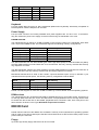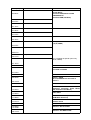
1
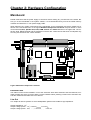
Q40
Q60
+
MAINBOARD
USER'S MANUAL
Version 01/2002
Chapter 1: Overview
Key Features
The Q40 mainboard is a 40 MHz high-performance Sinclair QL replacement mainboard based on the
Motorola MC68040 microprocessor with mathematical coprocessor and memory management unit. It
features 32 bit highcolor / highresolution graphics while maintaining QL hardware compatibility.
Like the original QL mainboard the Q40 is a complete solution including graphics, peripherals and sound.
It fits directly into an industry standard case. It doesn't need any parts from an existing QL and no CPU
card or keyboard interface.
The Q60 mainboard is a top-speed system, based on the Motorola MC68060 superscalar microprocessor
architecture. It includes all the features of the Q40, and adds even faster processing speed of up to 160
MIPS at 80 MHz.
RAM
4 MB up to 32 MB of DRAM. EDO or FPM memory modules can be used. Two 72 pin PS2-SIMM sockets simplify upgrading. No jumpers are required for size detection.
On the Q60 only EDO modules are supported, no FPM. Support for up to 128 MB of DRAM can be
realized by a special hardware option.
ROM
256 KB, data bus 32 bit wide by using two 16 bit devices. The mainboard supports up to 1 MB ROM capacity.
Graphics
On-board highspeed graphics chipset and 32 bit dual-ported video RAM. 72 Hz vertical refresh rate, noninterlaced in all modes, dual scan capability for the low resolutions. Supports multisync monitors with at
least 38 kHz horizontal frequency. Output connector options are 15 pin HD (VGA) or 9 pin SubD (PS/2).
Video modes
QL mode 8 256x256 pixel, 8 colors
QL mode 4 512x256 pixel, 4 colors
High color mode 512x256 pixel, 64K colors
High color mode 1024x512 pixel, 64K colors
Keyboard Interface
Port for MF-102 keyboards. 5 pin DIN connector.
Sound
Stereo digital-analog converters, 10kHz or 20kHz sample rate selectable. Line and headphone outputs.
Clock and Nonvolatile RAM
Battery buffered real time clock
2 KB nonvolatile static RAM
Disk Interface
Enhanced IDE Controller for 2 Harddisks (16 bit wide data transfer) or other IDE drives like CDROM
Floppy Controller for 2 HD floppies
Ports
2 serial ports with 115200 Baud
1 parallel port
1 joystick port
Disk interface and ports are on a small IDE / Multi IO card that belongs to the mainboard.
Extension Slot
The mainboard has two extension slots, one of them is occupied by the IDE / Multi IO card. There are 16
data lines and 20 address lines, all signals are buffered and have a well defined timing. Signals and pinout also allow many ISA cards to be used in the slot.
Board size
The Q40 and Q60 mainboards have a size of 8.2 x 6.3 inch and can be directly mounted in industry
standard cases for the AT form factor. (Mounting in ATX case should also be possible, but may require
special plate for connectors.)
Power Supply
An industry standard power supply can be directly plugged into the Q40 or Q60. A power connector
known from harddisks and 5.25“ Floppys is used.
Q40 / Q60 System
A complete Q40 or Q60 system can be a Q40 / Q60 Mainboard in combination with IDE Harddisk(s), CDROM or CD-RW drive and HD Floppy(s) mounted in an industry standard case with power supply, and a
MF-102 keyboard. Additional hardware extensions like Ethernet are supported by the extension slot.
Please note that not all operating systems may support the possible hardware options.
QL Compatibility
QL screen modes 4 and 8 are directly hardware compatible, ignoring mode 8 flashing. The 50 Hz frame
interrupt is available. Memory map and interrupt handling are similar, but ports have changed. Microdrives and the slow QL network are no longer supported.
Unpacking & Handling instructions
The Q40 or Q60 mainboard package should contain the following items:
1. The mainboard with CPU already installed
2. This User's Manual
3. Video cable with 15 pin HD or 9 pin SubD connector
4. IDE/IO card, second serial port and joystick cables/bracket, floppy cable, harddisk cable
5. PS/2-SIMM Memory module(s) (optional)
6. Sound cables (optional)
The Q40 or Q60 mainboard can be damaged by static electricity. Do not remove the mainboard from its
packing until you are ready to install it. Touch the systems chassis before handling the mainboard or any
component. Shipping may have lossened integrated circuits from their sockets. If any circuit appears
loose, press carefully to seat it firmly in its socket.
Chapter 2: Hardware Configuration
Mainboard
Please make sure that the power supply is turned off before making any connections to the board. Before you fix the mainboard in the system chassis, it is recommended that you first the install memory
modules and attach the 5 / 12V power supply cable.
When attaching any system components to the mainboard via the mainboard connectors, please pay attention to the correct direction. In the figure Mainbord Component Locations the pins number 1 of the
connectors Line Out, Speaker Out, LED, ROM selector and Video Out are on the upper side. The extension slots, DRAM sockets and the keyboard connector are constructed so that their counterparts only
fit if they are turned into the correct direction.
Figure: Mainbord Component Locations
Extension Slot
The IDE/IO card must be installed in one of the extension slots. Both extension slots are identical, so it
doesn't matter into which of the two slots a card is installed. When pressing a card into an extension slot,
hold the mainboard and take care not to bend it.
Line Out
Line Output for stereo systems or active loadspeaker systems with middle to high impedance.
Output impedance: 1 kΩ
Output voltage (Load = 1 kΩ): 700 mVpeak-peak ≈ 250 mVeff
Output voltage (Load = 10 kΩ ... ∞): 1200 mVpeak-peak ≈ 400 mVeff
Pin
1
2
3
Description
Left channel
Ground
Right channel
Speaker Out
Output for headphones or speakers with an impedance of 32 Ω or more. (Smaller impedances will not
damage the mainboard, but may not sound loud enough.)
Output impedance: 100 Ω
Output voltage (Load = 50 Ω): 1 Vpeak-peak ≈ 0.4 Veff
Output voltage (Load = 120 Ω): 2Vpeak-peak ≈ 0.7 Veff
Output voltage (Load = ∞): 3.5Vpeak-peak ≈ 1.2Veff
Pin
1
2
3
4
Description
Left channel
Ground
Right channel
Ground
Reset
Connector for a manual reset switch.
Setting Description
Open
Normal mode
Short
Hardware Reset
LED
Programmable LED Output.
Pin
1
2
Description
Cathode (Minus)
Anode (Plus)
ROM Selector
Selection of ROM function. The settings „2-3“ and „Open“ allow to divide the ROM into 128 KB parts,
and a jumper or switch selects which part is accessed.
Setting Description
1-2
Normal Operation with 256 KB ROM or more. (Default)
2-3
Open
Only use a jumper for this connection! It is not allowed to attach a cable between pins 1 and 2
of the ROM selector, because high-frequency signals are routed via this connection.
Use only lower 128 KB of the physical ROM device. A cable can be used to attach a switch
between pins 2 and 3.
Use only upper 128 KB of the physical ROM device and let them appear at the beginning of
the logical ROM address space(s).
Video Out
Analog Video Output for multisync monitors with at least 38 kHz horizontal frequency. A short cable is
provided with the mainboard, which leads the signals to a 15 pin HD or 9 pin SubD connector that can be
mounted at the case.
Please adjust the horizontal picture size and position on your monitor to avoid distortion at the border of
the display. Problems like flickering or wrong colors can be caused by too slow monitor timings or long
extension cords.
Pin
1
3
5
7
9
Description
Red
Green
Blue
Horizontal Sync
Vertical Sync
Pin
2
4
6
8
10
Description
Ground
Ground
Ground
Ground
No connection
Keyboard
Five-pin female DIN connector for MF-II keyboards (IBM-PC/AT keyboards). Electrically compatible to
PS/2 keyboards. Passive adaptors can be used.
Power Supply
Four-pin male connector for industry standard drive power supplies with +5V and +12V. To avoid bending the mainboard, press in the supply connector before fixing the mainboard in the case.
DRAM sockets
The mainboard lets you add up to 32 MB of DRAM via two memory banks on the mainboard. Each bank
has a 72-pin PS/2-SIMM socket. The mainboard supports the following memory configurations:
Bank 0
4 MB (single-sided)
16 MB (single-sided)
16 MB (single-sided)
16 MB (single-sided)
32 MB (double-sided)
Bank 1
None
None
4 MB (single-sided)
16 MB (single-sided)
none
Total memory
4 MB
16 MB
20 MB
32 MB
32 MB
The Q40 mainboard can use both DRAM types: Fast Page Mode (FPM) or Extended Data Out (EDO).
All PS/2 SIMM modules must be faster than 70 ns access time. Use only memory modules with decoupling capacitors on board!
The Q60 mainboard supports only EDO modules. All PS/2 SIMM modules must be 60 ns access time or
faster for the Q60. Use only memory modules with decoupling capacitors on board!
Mainboards manufactured in 2002 or later contain a special hardware option for up to 128 MB. If your
mainboard has this special option, the following memory configurations will be added:
Bank 0
64 MB (single-sided)
64 MB (single-sided)
64 MB (single-sided)
Bank 1
None
16 MB (single-sided)
64 MB (single-sided)
Total memory
64 MB
80 MB
128 MB
Please note that support for more than 32 MB of RAM may not be available under all operating systems.
ROM sockets
The mainboard uses two 16 data bit wide ROM or EPROM devices for 32 bit wide access. One device is
for the high data words and one for the low data words. The (EP)ROM device for the High Words must
be seated into the socket near to the DRAM. (EP)ROMs have a direction mark, whic must point to the
same direction as shown in the figure Mainbord Component Locations.
IDE/IO Card
Please read the manual of the IDE/IO card for details. Currently most combinations of operating systems
and IO cards on the Q40 or Q60 require that the Printer Mode ist set to SPP and the IRQ7 jumper for the
printer interrupt is removed.
Floppy
Up to two high density floppy disk drives can be connected.
IDE harddisks / CDROM / CD-Writer / DVD
The IDE/IO card supports 2 (optional 4) IDE harddisks or ATAPI devices. Please notice that special driver software might be required to support ATAPI devices like CDROM drives. Make shure that your device is supported by the software you use on the Q40 / Q60.
IDE harddisk used with the Q40 / Q60 should support PIO mode 2 or faster.
Serial, Parallel, Joystick
The IDE/IO card contains the serial port SER1 on a male 9 pin SubD connector and the parallel port
PAR1 on a female 25 pin SubD connector.
On a bracket that comes together with the IDE/IO card, you can find the serial port SER2 on a male 25
pin SubD connector and an analog joystick input on a female 15 pin SubD connector. The bracket must
be connected to the card.
Chapter 3: Memory Map
On the next page you can see the QL and the Q40/Q60 memory map as an overview about the physical
hardware locations.
A detailed description about the Q40 and Q60 hardware for programming operating systems or physical
device drivers is also available. This description is not included in this User's Manual, because it is not
helpful for normal operation and incorrect use can cause system crashes or data losses.
Address(hex)
QL
Q40
0000 0000
Internal ROM 48K
ROM 0 96K
(Normal Mode:
Read from ROM, Write to RAM
LOWRAM Mode:
Read from RAM, No Write)
0000 BFFF
0000 C000
0000 FFFF
External ROM 16K
0001 0000
External I/O 32K
0001 7FFF
0001 8000
0001 BFFF
Internal I/O 16K
0001 C000
0001 FFFF
External I/O 16K
0002 0000
Screen 0 32K
Screen 0 32K
RAM 96K
RAM up to 32608K
(4,16,20,32MB)
RAM 32K
0002 7FFF
0002 8000
0003 FFFF
0004 0000
Expansion RAM 512K
000B FFFF
000C 0000
000F FFFF
0010 0000
Peripheral ROMs 16 x 16K
Up to 130432K as special option only
(64,80,128MB)
01FF FFFF
FE00 0000
ROM 1 256K
lower 96K are ROM 0
FE03 FFFF
FE80 0000
Screen 1 1024K
32K at $FE820000 are mirrored at
Screen 0
FE8F FFFF
FF00 0000
FF00 0034
Master Chip
(Keyboard, Interrupts, Video Mode,
LED, Extension Slot Reset)
FF00 8000
FF00 8004
Audio-DACs
FF01 0000
FF01 8000
Address Decoder Chip
(ROM Mode Selection)
FF02 0000
FF02 1FFC
Nonvolatile RAM 2K
Realtime Clock
FF40 0000
FF7F FFFF
Extension Slot IO 1024K
FF80 0000
FFBF FFFF
Extension Slot MEM 1024K
All specifications are subject to change without notice. No responsibility is assumed for inaccuracies or errors.