1
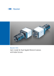
CLConfig Tool
User's Guide for Baumer CLConfigTool
2
Table of Contents
1. General Information������������������������������������������������������������������������������������������������� 4
1.1 CameraLink®����������������������������������������������������������������������������������������������������������� 4
1.2 General System Requirements������������������������������������������������������������������������������� 5
1.3 Installation��������������������������������������������������������������������������������������������������������������� 5
2. Baumer CL Config Tool�������������������������������������������������������������������������������������������� 6
2.1 Overview����������������������������������������������������������������������������������������������������������������� 6
2.2 Program Start���������������������������������������������������������������������������������������������������������� 6
2.3 Main Window���������������������������������������������������������������������������������������������������������� 7
2.3.1 Menu Application���������������������������������������������������������������������������������������������� 8
2.3.2 Menu System��������������������������������������������������������������������������������������������������� 8
2.3.3 Menu "?"����������������������������������������������������������������������������������������������������������� 8
2.4 Open Camera Window�������������������������������������������������������������������������������������������� 9
2.5 Camera Window����������������������������������������������������������������������������������������������������� 9
2.5.1 Menu Bar�������������������������������������������������������������������������������������������������������� 10
2.5.2 Features����������������������������������������������������������������������������������������������������������11
2.5.3 TestPattern����������������������������������������������������������������������������������������������������� 18
2.6 Serial Communication Window����������������������������������������������������������������������������� 20
2.7 BGAPI Options ����������������������������������������������������������������������������������������������������� 21
2.7.1 System����������������������������������������������������������������������������������������������������������� 21
2.7.2 Cameras��������������������������������������������������������������������������������������������������������� 22
2.7.3 Trace�������������������������������������������������������������������������������������������������������������� 22
3
1. General Information
The CL Config Tool, part of the generic application programming interface from Baumer,
is the perfect evaluation tool for Baumer cameras with Camera Link® interface. It allows to
investigate the extensive functionality within our innovative cameras.
Read these manual carefully and observe the notes and safety instructions!
Keep the User´s guide store in a safe place and transmit them to the eventually following
users.
Target group for this User´s Guide
This User's Guide is aimed at experienced business users, which want to integrate
camera(s) into a vision system.
Copyright
Any duplication or reprinting of this documentation, in whole or in part, and the reproduction of the illustrations even in modified form is permitted only with the written approval of
Baumer. This document is subject to change without notice.
Classification of the safety instructions
In the User´s Guide, the safety instructions are classified as follows:
Notice
Gives helpful notes on operation or other general recommendations.
1.1 CameraLink®
The CameraLink® interface was especially developed for cameras in machine vision applications and provides high transfer rates and low latency. Depending on the configuration (Base, Medium or Full) the transfer rate adds up to 625 MBytes/sec.
▪▪ Base (max. 24 Bit per Clock)
▪▪ Medium (max. 48 Bit per Clock)
▪▪ Full (max. 64 Bit per Clock)
Cameras of the Baumer SXC series are equipped with a CameraLink® Base interface.
Cameras of the Baumer HXC series are equipped with a CameraLink® Full interface.
4
1.2 General System Requirements
Single-camera system
Multi-camera system
Minimum
Recommended
Minimum
Recommended
CPU
Intel® Pentium®4
or comparable
Intel® Core™ Duo comparable processor
processor
Clock
2.5 GHz
> 2.5 GHz
2.5 GHz
3 GHz
RAM
1024 MB
2048 MB
2048 MB
> 2048 MB
Operating
Microsoft® Windows® XP incl. Service Pack 2 or higher
Microsoft® Windows® XP x64 incl. Service Pack 2 or higher
system
Microsoft® Windows Vista™ 32 / 64 bit systems
(OS)
Microsoft® Windows® Windows 7 32 / 64 bit systems
Graphics
recommended resolution 1280 x 1024, color depth at least 16 bit
Framework
Windows® OS: .NET™ Framework 2.0 or higher
1.3 Installation
The CL Config Tool is part of the installation package Baumer-GAPI. The CL Config Tool
can be start directly from CD and requires no installation.
Notice
The log file (trace), is written in the directory where the program is located. When you
start the program from CD and you want to write a log file, you must change the path to
write the log file.
Set the path under: System → Options → Trace
5
2. Baumer CL Config Tool
2.1 Overview
CL Config Tool is used to control cameras with CameraLink® interface. It does not grab
and display images.
2.2 Program Start
Insert the CD. → The following window appears (if Autorun is enabled).
Click "Install" → The following window appears.
Click "Start CL Configtool" to start the program.
Notice
If CLConfig tool does not start, check that .NET™ Framework 2.0 or higher is installed
on your system.
6
2.3 Main Window
Afterward the main window (Fig. 1) appear.
◄ Figure 1
Main window of the
Baumer CLConfigTool
Here you will find a menubar with two menus, which are described in more detailed within
the next paragraphs.
Notice
When you first start you are prompted for the path to the Cameralink® serial DLL.
For Windows 7 you need Admin rights to copy the DLL. Start the Tool with a right-click at
the CLConfigTool.exe-file and select "Run as administrator" (Windows 7 / 64 bit only).
Type the path where the file is ( e.g. "clsermtx.dll"). This file is provided by the Frame
grabber manufacturer.
This path is stored in the Windows registry under:
HKEY_LOCAL_MACHINE \ SOFTWARE \ CameraLink
After setting the path, select "System" → "Rescan".
Notice
If you still do not see the camera, please check the cables.
7
2.3.1 Menu Application
Figure 2 ►
Menu Application
By selecting the menu item "Select Serial path..." you can specify the path to the serial
DLL.
The path must be specified if by the start of the software no camera is found or you have
installed a new frame grabber.
Notice
If the path already exists you will overwrite it with this process!
Notice
For Windows 7 you need Admin rights to copy the DLL. Start the Tool with a right-click at
the CLConfigTool.exe-file and select "Run as administrator" (Windows 7 / 64 bit only).
This path is stored in the Windows registry under the following key:
HKEY_LOCAL_MACHINE \ SOFTWARE \ CameraLink
This file is provided by the Frame grabber manufacturer. Type the path where the file
(e.g."clsermtx.dll") is.
After setting the path, select "System" → "Rescan".
By selecting the menu item "Exit" the tool can be aborted.
2.3.2 Menu System
Figure 3 ►
Menu System
This menu contains two items: "Rescan" and "Options".
2.3.2.1 Rescan
Select "Rescan" after "Select Serial Path...", when you have connected a new camera.
2.3.2.2 Options
Here several options regarding to the interface and the camera can be adjusted. Further
information on the options window will be given in section 2.7.
2.3.3 Menu "?"
Figure 4 ►
Information Window
The only item here is "Info", which causes the display of the Baumer-GAPI version.
8
2.4 Open Camera Window
Make a double click on the camera. The camera turns green and the camera window with
the features opens.
◄ Figure 5
Main window with Camera Window
2.5 Camera Window
The camera window (Fig. 4) is divided in three areas:
▪▪ Menu Bar (1),
▪▪ Feature Control (2),
▪▪ Serial Communication Window (3)
which are described in the following paragraphs.
SX80c
Camera
2
Serial Communication Window
>
>
3
◄ Figure 6
Framing of the camera
window.
9
Figure 7 ►
Screenshot of Camera
Window
2.5.1 Menu Bar
The menu bar contains one menu:
▪▪ Camera.
2.5.1.1 Menu "Camera"
Figure 8 ►
Menu "Camera"
Here a copy of the configuration file (.xml) of the camera can be stored to the PC.
10
2.5.2 Features
By selecting a feature (button) in this area, an associated parameter list is opened.
Notice
Only features supported by the camera appears!
The availability and/or the status of a particular feature is indicated by
several icons.
Icon
Status
This feature is enabled.
This feature is disabled.
This feature is not supported by the software.
This feature is not supported by the hardware.
Depending on an other feature, this one is temporary
locked.
Feedback error on feature.
Some of the features are camera-specific.
Therefore the features are labeled within this document:
Label
Description
This feature is available on monochrom cameras.
This feature is available on color cameras.
2.5.2.1 BrightnessCorrection
On Binning Mode, an aggregation of charge carriers takes place.
This may cause an overload and therefore an overexposed image. For prevention of this effect, the Brightness Correction was
introduces.
Notice
This feature is available in Binning Mode only.
2.5.2.2 Camera Information
Here several information on the employed camera, such as serial number, model name and firmware version, are provided.
11
2.5.2.3 DefectpixelCorrection
During the lifecycle of a camera, hot or cold pixels can develop.
In order to correct these pixels, the so-called defect pixel map
(or list) was introduced to Baumer cameras.
With this feature, Baumer offers the possibility to get the current
defectpixel list from the connected camera and set defect pixel.
Notice
The coordinates reference to Full Frame Format.
With a connected SXC Camera you can not set defect pixel.
2.5.2.4 Device Clock
The speed (Mhz) to readout the sensor can be configured by
using this feature. This reduces the data throughput at the frame
grabber.
By reducing the clock, you can prevent buffer overflows, reduce
power consumption and can use longer cables.
Notice
The offered speed are dependet from the connected camera.
2.5.2.5 Exposure
Here the exposure time can be adjusted via entry or slider.
Notice
The values are given in µsec.
12
2.5.2.6 Flip Image
With this feature you can mirror the image.
2.5.2.7 FramesPerSeconds
Wiith this feature the maximum frame rate of the camera can be
predefined.
Notice
Special value 0 = "Freerun"
Camera takes images at full frame rate without external
trigger.
2.5.2.8 Gain
Here the amplification factor can be adjusted via entry or slider.
2.5.2.9 Gamma
Here the factor γ for the gamma correction can be set.
Notice
LookUpTable Hardware needs to be enabled to activate this
feature.
13
2.5.2.10 HDR
HDR is a technique that allows a greater dynamic range of luminance between the lightest and darkest areas of an image.
Here you can set the HDR parameters.
2.5.2.11 ImageFormat
Here the adjustment of the image format takes place.
Within the drop down menu all available image formats of the
employed camera are displayed.
14
2.5.2.12 Interface Tabs
Here you can set the number of interface tabs. This is the number of parallel CameraLink channels for the tranfer of the images
from the camera to the computer.
Notice
Cameralink Base (one connector) 1,2,3 Taps
Cameralink Medium (two connectors) 3,4 Taps
Cameralink Full (two connectors) 8 Taps
Choose only 1,2,3,4 or 8 Taps!
2.5.2.13 I/O's
This feature offers the possibility of configuring the digital in- and
outputs of the camera.
For an input, the Debouncer tLow and tHigh can be adjusted in
µsec.
For an User output, the respective signal source can be selected.
You can choose how the update of the IO status should be made
You can select "permanently" or specify a time in µsec.
15
2.5.2.14 LookUpTable Hardware
By this feature, the internal Look-Up-Table can be loaded and
enabled.
Furthermore, individual values can be set. Therefore the specific value needs to be defined and set within the area "Set LUT
Value" at the bottom of the feature display. Afterwards the LUT
needs to be updated via "Update" button.
Notice
The feature "Gamma" overwrites the LUT settings.
2.5.2.15 Offset
Here the analog offset (blacklevel) can be adjusted.
Notice
The value is depending on the connected camera.
2.5.2.16 PartialScan (ROI)
This feature offers the possibility of defining a so-called Region
of interest (ROI).
Once the feature is enabled, the coordinates of the start respectively end point of the ROI can be adjusted by the sliders.
Notice
You must stop the camera before you can activating PartialScan.
16
2.5.2.17 PixelFormat
By this feature the pixelformat (depending on the current set image format) can be selected.
Below the drop down menu, several information on the pixel format are displayed.
Notice
The pixel format depends on the employed image format.
2.5.2.18 ReadoutMode
This feature refers to the timings of image acquisition. Here the
operation mode can be switched between overlapped and sequential read out.
2.5.2.19 Reset
By processing this feature, the camera will be reset to factory
settings.
Notice
Please stop the camera before reset.
2.5.2.20 Sensor Digitization Taps
This feature depends on the sensor of the employed camera.
The CMOSIS sensors, employed in Baumer HXC cameras can
be read at up to 16 channels.
The CMOSIS sensors, employed in Baumer SXC cameras can
be read at up to 4 channels.
2.5.2.21 Start
Here the camera (image acquisition) can be started or stopped.
17
2.5.2.22 Temperature
For cameras with integrated temperature sensor the current temperature at the camera board can be measured and displayed
by this feature.
This can occure manually via the "Update" button or in a predefined "permanent" interval.
2.5.3 TestPattern
Here several test patterns, generated in the camera, can be selected and displayed within the image view.
These patterns serve as a test tool for correct data transmission
between camera and PC.
2.5.3.1 Trigger
This feature offers the possibility to switch the camera to the
trigger mode.
Once "Trigger" is enabled, the trigger source as well as the state
of the trigger signal on which the camera should react is adjustable.
The button "Do it" provides the possibility of sending a software
trigger to the camera.
Notice
"TriggerActivation" is only selectable on trigger source
HARDWARE1-7.
18
2.5.3.2 User Set
Here several possibilities regarding to user sets are offered:
▪▪ Loading a user set
▪▪ Loading of BGAPI_USERSET_FACTORY will reset the
camera
▪▪ Storing of the current camera configuration to a selected user
set
▪▪ Selection of a default user set and therefore specification of a
specific start behaviour of the camera
Notice
Factory settings can not be overwritten.
Please stop the camera before using this feature.
2.5.3.3 WhiteBalance
Once this feature is enabled, it provides two possibilities of color
correction:
▪▪ One Push White Balance (via White Balance ROI)
Here the white balance is processed by employment of white
balance factors, which are determined for a particular area
(ROI) of the image. This ROI is adjustable via direct entry to
the fields "Left", "Top","Right" and "Bottom" or by usage of
the sliders.
▪▪ User-specific Color Adjustment (via White Balance Factors)
Here the correction factor for each color can be adjusted
user-specific.
Notice
At SXC cameras, you can not change White Balance ROI! It
is only displayed.
19
2.6 Serial Communication Window
With the "Serial Communication Window", you can write commands directly in the register
of the camera.
Notice
This configuration method should only be used by experienced customers!
Example: Set the exposure time to 4000 µs (4000DEC = fa0HEX) using register address
0xf0004010.
!
These zeros must be ignored
when entering in the Serial
communication window!
To start a command, the first charakter to send is
a LF (0x0a) followed by the command type which
could be either „r“ for read or „w“ for write.
f0004010
Figure 9 ►
Structure of inputs
The end of a command is marked
using a LF-CR (0x0a; 0x0d) sequence
0000
00000fa0
wf000401000000fa0
Your input in the Serial Communication Window must be: wf000401000000fa0
Figure 10 ►
Serial Communication
Window
Notice
For a summary of the commands, see the register description of the camera.
20
2.7 BGAPI Options
2.7.1 System
BGAPI Options
1 - Tab "System"
2 - Interface Selector
3 - Information
4 - GVS Driver Model
5 - Force IP
6 - Command
7 - Interfaces
8 - Control Monitor
9 - Feature Status
10 - Close Button
◄ Figure 11
Option Window
2.7.1.1 Interface Selector
Currently there is only one option here:
BGAPICameraLink(BGAPIX_DEVICETYPE_COMMONPCI_CAMERALINK)
CL Config Tool only supports CameraLink.
2.7.1.2 Information
In this area several information on the selected interface are displayed.
2.7.1.3 GVS Driver Model
Not available with CameraLink.
2.7.1.4 Force IP
Not available with CameraLink.
2.7.1.5 Command
Not available with CameraLink.
2.7.1.6 Interfaces
Not available with CameraLink.
2.7.1.7 Feature Status
Here several information, whether a feature is supported or not, are stated.
21
2.7.2 Cameras
1 - Tab "Cameras"
BGAPI Options
2 - Display Options
Figure 12 ►
Tab Cameras
By this feature the start behaviour of the camera is controlled.
▪▪ Enabling the checkbox "Start image acquisition direct after init" means the camera is
started immediatly after the camera window is opened.
▪▪ Disabling this checkbox means the image acquisition needs to be started manually.
2.7.3 Trace
Notice
The log file (trace), is written in the directory where the program is located. When you
start the program from CD and you want to write a log file, you must change the path to
write the log file.
Set the path under: System → Options → Trace
1 - Tab "Trace"
BGAPI Options
2 - Trace Support
3 - Global trace settings
5
6
7
8
9
4 - Enable Trace
5 - Trace Output
6 - Trace Mask
7 - Trace Output Options
8 - Trace Level
9 - Reserved for future
functions
Figure 13 ►
Tab Trace
2.7.3.1 Tab "Trace"
On this tab you can set the trace output.
2.7.3.2 Trace Support
Currently there is only one option here - BGAPI_TRACESUPPORT_GLOBAL, which will
trace events.
2.7.3.3 Enable Trace
Once this checkbox is activated tracing is enabled for the selected items within the boxes
22
of this dialog.
2.7.3.4 Trace Output
Here the output of the trace object can be controlled.
Therefore the following options are available:
File
The content of the trace object will be stored in a file on the PC.
Callback
The content of the trace object will be displayed in a message window.
Debugger
The content of the trace object will be directed to an external debugger.
2.7.3.5 Trace Mask
By this checkboxes the content of the trace object is adjustable.
2.7.3.6 Trace Output Options
Here several information can be added to the traced events:
Timestamp
The timestamp of the event is logged and displayed.
Timestamp Diff The interval from the last trced event to the current one is displayed.
Prefix
not used.
New line
Linebreak is added to every output line.
Level
Here the levelfiltering (see 3.5.3.8.) can be enabled.
2.7.3.7 Trace Level
By this checkboxes, the levelfiltering can be adjusted.
23
Subject to change without notice. Printed in Germany 08/11.
v1.1
11054315
Technical data has been fully checked, but accuracy of printed matter not guaranteed.
Baumer Optronic GmbH
Badstrasse 30
DE-01454 Radeberg, Germany
Phone +49 (0)3528 4386 0 · Fax +49 (0)3528 4386 86
[email protected] · www.baumer.com