1
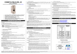
-1-
Wi-Fi PORT SERVERS
USER’S GUIDE
TABLE OF CONTENTS
I
PRODUCT LINE SPECIFICATIONS......................................................................... 3
I.1
I.2
I.3
I.4
I.5
WL-COMETH PRODUCT SPECIFICATIONS ............................................................. 3
WL-DONGLE PRODUCT SPECIFICATIONS .............................................................. 6
WL-DONGLE-OEM PRODUCT SPECIFICATIONS .................................................... 8
WL-IDA/S PRODUCT SPECIFICATIONS .................................................................. 11
WL-ABOARD/S PRODUCT SPECIFICATIONS ........................................................ 14
II
ARCHITECTURE OVERVIEW ................................................................................ 17
III
ADMINISTRATION .................................................................................................... 18
III.1
III.2
III.3
III.4
IV
DOWNLOADING THE FIRMWARE....................................................................... 24
IV.1
IV.2
V
ACTIVATE THE RELEVANT FIRMWARE .................................................................. 24
CONFIGURE A SLIP CONNECTION ........................................................................ 25
TROUBLESHOOTING ............................................................................................... 40
V.1
V.2
VI
ADMINISTRATION THROUGH RS232 SERIAL PORT ................................................ 19
ADMINISTRATION THROUGH WLAN.................................................................... 20
TCP/IP CONFIGURATION...................................................................................... 21
ADMINISTRATION COMMANDS .............................................................................. 23
CHECKING THE HARDWARE ................................................................................... 40
CHECKING WLAN TOPOLOGY .............................................................................. 42
OTHER DOCUMENTATION .................................................................................... 43
11 Mb WiFi port servers user’s guide (DTUS058) release A0, january 23, 2006
-2-
Wi-Fi PORT SERVERS USER GUIDE
COPYRIGHT (©) ACKSYS 2004-2006
This document contains information protected by Copyright.
The present document may not be wholly or partially reproduced, transcribed, stored
in any computer or other system whatsoever, or translated into any language or
computer language whatsoever without prior written consent from ACKSYS – ZA
VAL JOYEUX – 10, rue des entrepreneurs – 78450 Villepreux – France
REGISTERED TRADEMARKS ®
• ACKSYS is a registered trademark of ACKSYS.
• Windows is a registered trademark of MICROSOFT.
NOTICE
ACKSYS ® gives no guarantee as to the content of the present document and takes
no responsibility for the profitability or the suitability of the equipment for the
requirements of the user.
ACKSYS ® will in no case be held responsible for any errors that may be contained
in this document, nor for any damage, no matter how substantial, occasioned by the
provision, operation or use of the equipment.
ACKSYS ® reserves the right to revise this document periodically or change its
contents without notice.
ZA Val Joyeux
10, rue des entrepreneurs
78450 Villepreux - FRANCE
Telephone: +33 (0)1 30 56 46 46
Fax:
+33 (0)1 30 56 12 95
Web:
www.acksys.fr
Hotline:
[email protected]
Sales:
[email protected]
11 Mb WiFi port servers user’s guide (DTUS058) release A0, january 23, 2006
-3-
I
I.1
PRODUCT LINE SPECIFICATIONS
WL-COMETH Product specifications
I.1.1 Characteristics
Wi-Fi 802.11b port server with one serial port
Metal housing
RS232, RS422A/RS485 serial interface
External DC power supply for WL-COMETH-DC
Integrated AC power supply for WL-COMETH
Also available in weather proof version (IP65) (with plastic housing)
I.1.2 Power supply
WL-COMETH-DC : screw terminal connector (3 pins)
External power 9 to 36 Vdc
Power consumption : 3W max (300 mA at 9 Vdc)
PIN
Signal name
Description
1
GND
Protective ground
2
+VDC
Positive power supply
3
EARTH
Ground power supply
WL-COMETH : Integrated universal 85-264 Vac
Main power 85 to 264 Vac, 47-440 Hz, 3W max
Power supply protection by current limitation
I.1.3 WLAN interface
WIFI 802.11b interface, speed 1,2,5.5,11 Mbps
300 m (984 ft) nominal range (open space) from access point, 60 m
(200 ft) in other cases.
I.1.4 Mechanical characteristics
Metal version
Metal housing
Size: 10×17×4 cm (4×6.7×1.6 in) (antenna plugs not included,
fastening included)
Weigth : 0.450 Kg (0.99 lbs)
Weatherproof version
Plastic housing
Size: 11,6×16,4×36 (4.6×6×13 in) (antenna plugs not included,
fastening included)
Weigth : 0.350 Kg (0.77 lbs)
I.1.5 Serial interface
The type of serial interface is selectable through the administration
system. You can use RS232 or RS422A/RS485 but not both
simultaneously.
The serial interface benefits a 15 kV ESD protection.
11 Mb WiFi port servers user’s guide (DTUS058) release A0, january 23, 2006
-4-
I.1.5.1 RS232
Full RS232 EIA/TIA 574 Serial interface
male DB9 with DTE cabling
PIN
1
2
3
4
5
6
7
8
9
Signal
name
DCD
RxD
TxD
DTR
GND
DSR
RTS
CTS
RI
Direction
Input
Input
Output
Output
Digital ground
Input
Output
Input
Input
I.1.5.2 RS422A/RS485
EIA RS422A/RS485 – CCITTV11 serial interface
Master or Slave selection by software
Built-in automatic turn-around
Line polarization and terminating resistor selection by switch
RS422A/RS485 protection against temporary line voltage surges by
peaks, breakdown voltage +/-6.5V in common and differential mode,
capacitance 0.3 kW over 8/20 µs
male DB9
Pin
1
2
3
4
5
6
7
8
9
RS422A
RS485
Reserved
Reserved
Reserved
Reserved
TxB
Reserved
RxB
TRxB
Digital ground
Reserved
Reserved
Reserved
Reserved
TxA
Reserved
RxA
TRxA
Terminating resistor enable
Terminating resistor disable
Polarisation resistor enable
Polarisation resistor disable
push switch in on position
push switch in off position
push both switches in on position
push both switches in off position
11 Mb WiFi port servers user’s guide (DTUS058) release A0, january 23, 2006
-5-
I.1.6 Led indicators
Power
Diagnostic / general-purpose mode / error detection / reboot
indicator
Asynchronous interface Rx/Tx activity
WLAN interface Rx/Tx activity
RF signal quality on WLAN interface (6 LEDs)
Enabled serial interface (RS232 / RS4xx)
I.1.7 Switches
One switch allows selection between the two operating modes
(Administration / Exploitation).
Two switches for polarization resistor.
One switch for terminating resistor.
I.1.8 Antennas
Two omni-directional antennas, 2dBi. You can replace them by an
antenna with more gain, through the external antenna (RSMA)
connector.
I.1.9 Environmental limitations
Operating temperature: 0°C to 65°C (32 to 149 °F).
Storage temperature: -40°C to +85°C (-40 to +185 °F).
Humidity: 0-95% RH (without condensation)
11 Mb WiFi port servers user’s guide (DTUS058) release A0, january 23, 2006
-6-
I.2
WL-DONGLE product specifications
I.2.1 Characteristics
Wifi 802.11b port server with one serial port
Metal housing
WIFI interface (802.11b) at 11 Mbit/s
RS232 15 kV ESD protection
External power supply 5 VDC with jack connector
I.2.2 Power supply
External power supply 5 VDC
Power consumption : 3W max
Female jack
GND
+5 Vdc
I.2.3 WLAN interface
WIFI 802.11b interface, speed 1, 2, 5.5, 11 Mbps
300 m (984 ft) nominal range (open space) from access point, 60 m
(200 ft) in other cases.
I.2.4 Mechanical characteristics
Metal housing
Size: 7.9×5.8×2.3 cm (3×2.2×0.8 in) (antenna plugs not included)
Weight : 0.110 Kg (0.24 lbs)
I.2.5 Serial interface
Full RS232 EIA/TIA 574 Serial interface
male DB9 with DTE cabling
PIN
1
2
3
4
5
6
7
8
9
Signal
name
DCD
RxD
TxD
DTR
GND
DSR
RTS
CTS
RI
Direction
Input
Input
Output
Output
Digital ground
Input
Output
Input
Input
11 Mb WiFi port servers user’s guide (DTUS058) release A0, january 23, 2006
-7-
I.2.6 Led indicators
Diagnostic / general-purpose mode / error detection / reboot
indicator
Asynchronous interface Rx/Tx activity
WLAN interface Rx/Tx activity
I.2.7 Switches
One switch allows selection between the two operating modes
(Administration / Exploitation).
I.2.8 Antennas
One omni-directional antenna. You can replace it by an antenna with
more gain, through the external antenna (RSMA) connector.
I.2.9 Environmental limitations
Operating temperature: -10°C to 60°C (14 to 140 °F).
Storage temperature: -40°C to +85°C (-40 to +185 °F).
Humidity: 0-95% RH (without condensation)
11 Mb WiFi port servers user’s guide (DTUS058) release A0, january 23, 2006
-8-
I.3
WL-DONGLE-OEM product specifications
I.3.1 Characteristics
Wifi 802.11b port server with one serial port
WIFI interface (802.11b) at 11 Mbit/s
RS232 (DB9 connector) or TTL (HE10 connector) interface
External power supply 3.3/5 VDC
I.3.2 Power supply
External power supply 3.3 Vdc or 5 Vdc on the HE10 connector
I.3.3 WLAN interface
WIFI 802.11b interface, speed 1, 2, 5.5, 11 Mbps
300 m (984 ft) nominal range (open space) from access point, 60 m
(200 ft) in other cases.
I.3.4 Mechanical characteristics
(All sizes in millimeters)
11 Mb WiFi port servers user’s guide (DTUS058) release A0, january 23, 2006
-9-
I.3.5 Serial interface
Full RS232 EIA/TIA 574 Serial interface
I.3.5.1 WL-DONGLE-OEM-232 version
male DB9 with DTE cabling
PIN
1
2
3
4
5
6
7
8
9
Signal
name
DCD
RxD
TxD
DTR
GND
DSR
RTS
CTS
RI
Direction
Input
Input
Output
Output
Digital ground
Input
Output
Input
Input
I.3.5.2 WL-DONGLE-OEM-TTL version
HE10
Pin
2
15
16
3
7
8
9
13
Characteristics
3.3V (3Wmax)
5V (3Wmax)
Inputs (3.3V)
Vih =1.8Vmin
Vil =1.0Vmax
14
6
5
12
1
4
10
11
Output (3.3V)
Voh =2.4Vmin
Vol =0.4Vmax
24mA
Outputs (2.5V)
Voh =1.8Vmin
Vol =0.4Vmax
4mA
Outputs (3.3V)
Voh =3.1Vmin
Vol =0.2Vmax
32mA
Signal
Power supply if 5V is not used
Power supply if 3.3V is not used
GND
RI (active low)
RX (active low)
DCD (active low)
DSR (active low)
CTS (active low)
Enable the administration mode through the
serial port (active low)
TX (active low)
RTS (active low)
DTR (active low)
Turn-around for RS485 (active high)
Driver for WLAN activity LED (active low)
Driver for SERIAL activity LED (active high)
Driver for DIAG activity LED (active high)
11 Mb WiFi port servers user’s guide (DTUS058) release A0, january 23, 2006
- 10 -
I.3.6 Led and status indicators
4 TTL status outputs on the HE10 connector:
Diagnostic / general-purpose mode / error detection / reboot
indicator
Asynchronous interface Rx/Tx activity
WLAN interface Rx/Tx activity
RS485 turn-around indicator
The first three status outputs are also displayed on LEDs.
I.3.7 Switches
1 TTL control intputs on the HE10 connector:
Operating mode (Administration / Exploitation).
I.3.8 Antennas
Micro-FLH connector. One omni-directional antenna is provided with
the –EVAL versions only. Antennas can be ordered separately.
I.3.9 Environmental limitations
N/A.
11 Mb WiFi port servers user’s guide (DTUS058) release A0, january 23, 2006
- 11 -
I.4
WL-IDA/S product specifications
I.4.1 Characteristics
Wi-Fi 802.11b port server with one serial port
Metal case, DIN RAIL assembly
RS232, RS422A/RS485 serial interface
External DC power supply
I.4.2 Power supply
WL-IDA/S : screw terminal connector (3 pins)
External power 7 to 60 Vdc
Power consumption : 3W max
PIN
Signal name
Description
1
EARTH
Protective ground
2
+VDC
Positive power supply
3
GND
Ground power supply
I.4.3 WLAN interface
WIFI 802.11b interface, speed 1,2,5.5,11 Mbps
300 m (984 ft) nominal range (open space) from access point, 60 m
(200 ft) in other cases.
I.4.4 Mechanical characteristics
Metal housing
Size: 110 × 72.50 × 32 mm (L × W × H) (antenna plugs not included,
fastening included)
Weigth : 271.3 g (0.6 lbs)
I.4.5 Serial interface
The type of serial interface is selectable through the administration
system. You can use RS232 or RS422A/RS485 but not both
simultaneously.
The serial interface benefits a 15 kV ESD protection.
11 Mb WiFi port servers user’s guide (DTUS058) release A0, january 23, 2006
- 12 -
I.4.5.1 RS232
Full RS232 EIA/TIA 574 Serial interface
male DB9 with DTE cabling
PIN
1
2
3
4
5
6
7
8
9
Signal
name
DCD
RxD
TxD
DTR
GND
DSR
RTS
CTS
RI
Direction
Input
Input
Output
Output
Digital ground
Input
Output
Input
Input
I.4.5.2 RS422A/RS485
EIA RS422A/RS485 – CCITTV11 serial interface
Master or Slave selection by software
Built-in automatic turn-around
Line polarization and terminating resistor selection by switch
RS422A/RS485 protection against temporary line voltage surges by
peaks, breakdown voltage +/-6.5V in common and differential mode,
capacitance 0.3 kW over 8/20 µs
5 pins connector
Pin
Mode
RS422
(4 pins)
RS485
(2 pins)
1
2
3
4
5
TxA
TxB
RxA
RxB
GND
Output Output Input Input
TxRxA TxRxB
GND
In/Out In/Out
Terminating resistor enable
Terminating resistor disable
Polarisation resistor enable
Polarisation resistor disable
push switch in on position
push switch in off position
push both switches in on position
push both switches in off position
11 Mb WiFi port servers user’s guide (DTUS058) release A0, january 23, 2006
- 13 -
I.4.6 Led indicators
Power
Diagnostic / general-purpose mode / error detection / reboot
indicator
Asynchronous interface Rx/Tx activity
WLAN interface Rx/Tx activity
RF signal quality on WLAN interface (4 LEDs)
I.4.7 Switches
One switch allows selection between the two operating modes
(Administration / Exploitation).
Two switches for polarization resistor.
One switch for terminating resistor.
I.4.8 Antennas
One omni-directional antenna, 2dBi. You can replace it by an
antenna with more gain, through the external antenna (RSMA)
connector.
I.4.9 Environmental limitations
Operating temperature: -10°C to 60°C (14 to 140 °F).
Storage temperature: -40°C to +80°C (-40 to +176 °F).
Humidity: 0-99% RH (without condensation)
11 Mb WiFi port servers user’s guide (DTUS058) release A0, january 23, 2006
- 14 -
I.5
WL-ABOARD/S product specifications
I.5.1 Characteristics
Wi-Fi 802.11b port server with one serial port
Cast aluminum housing tailored for all on-road requirements (sealed
to IP66, AUTOMOTIVE E2, shock & vibration proof MIL-STD-810F)
RS232, RS422A/RS485 serial interface
External DC power supply (not supplied)
I.5.2 Power supply
WL-ABOARD/S : screw terminal connector (3 pins)
External power supply 7 to 60 Vdc (3 W max.)
Internal (J1)
External cable
Signal name
connector pin
color
1
GND
black
2
+VDC
red
I.5.3 WLAN interface
WIFI 802.11b interface, speed 1,2,5.5,11 Mbps
300 m (984 ft) nominal range (open space) from access point, 60 m
(200 ft) in other cases.
I.5.4 Mechanical characteristics
Wall mounting
Cast aluminum housing (sealed to IP66, AUTOMOTIVE E2, shock &
vibration proof MIL-STD-810F)
Size: 115 x 64 x 35 mm (L x W x H) (antenna plugs not included)
Weigth : 0.375 kg (0.83 lbs)
I.5.5 Serial interface
The type of serial interface is selectable through the administration
system. You can use RS232 or RS422A/RS485 but not both
simultaneously.
The serial interface benefits a 15 kV ESD protection.
The internal J2 connector is prolonged outside the box with a cable
holding a DB9 connector.
I.5.5.1 Internal connector (J2)
Pin
Mode
3
4
RI
DCD
in
in
RxA
RS422
in
(4 wires)
RS485 TxRxA
(2 wires) In / out
Grey Black
Color
RS232
5
6
7
8
RX
in
TX
out
TxB
out
RTS
out
CTS
in
TxA
out
Brown
Red
Blue
9
10
11
DTR
DSR
GND
out
in
data
RxB
In
TxRxB
In / out
Purple Orange Green Yellow
11 Mb WiFi port servers user’s guide (DTUS058) release A0, january 23, 2006
- 15 -
I.5.5.2 RS232
Full RS232 EIA/TIA 574 Serial interface
male DB9 with DTE cabling
PIN
1
2
3
4
5
6
7
8
9
Signal
name
DCD
RxD
TxD
DTR
GND
DSR
RTS
CTS
RI
Direction
Input
Input
Output
Output
Digital ground
Input
Output
Input
Input
I.5.5.3 RS422A/RS485
EIA RS422A/RS485 – CCITTV11 serial interface
Master or Slave selection by software
Built-in automatic turn-around
Line polarization and terminating resistor selection by switch
RS422A/RS485 protection against temporary line voltage surges by
peaks, breakdown voltage +/-6.5V in common and differential mode,
capacitance 0.3 kW over 8/20 µs
male DB9
Pin
1
2
3
4
5
6
7
8
9
RS422A
RS485
Reserved
Reserved
Reserved
Reserved
TxB
Reserved
RxB
TRxB
Digital ground
Reserved
Reserved
Reserved
Reserved
TxA
Reserved
RxA
TRxA
Terminating resistor enable
Terminating resistor disable
Polarisation resistor enable
Polarisation resistor disable
push switch 4 in on position
push switch 4 in off position
push switches 2-3 in on position
push switches 2-3 in off position
11 Mb WiFi port servers user’s guide (DTUS058) release A0, january 23, 2006
- 16 -
I.5.6 Led indicators
Power
Diagnostic / general-purpose mode / error detection / reboot
indicator
Asynchronous interface Rx/Tx activity
WLAN interface Rx/Tx activity
“RS422/RS485 activated” indicator
I.5.7 Switches
One switch allows selection between the two operating modes
(Administration / Exploitation).
Two switches for polarization resistor.
One switch for terminating resistor.
I.5.8 Antennas
One omni-directional antenna, 2dBi. You can replace it by an
antenna with more gain, through the external antenna (RSMA)
connector.
I.5.9 Environmental limitations
Operating temperature: -25°C to 80°C (-13 to 176 °F).
Storage temperature: -40°C to +80°C (-40 to +176 °F).
Humidity: 0-99% RH (without condensation)
11 Mb WiFi port servers user’s guide (DTUS058) release A0, january 23, 2006
- 17 -
II
ARCHITECTURE OVERVIEW
This line of products is equipped with a replaceable embedded firmware.
The firmware comes in several flavors to suit different application needs
(COM port redirection, MODBUS, multidrop connections, etc.)
The factory preinstalled firmware is called SERVERCOM and is mainly
used for virtual COM port redirection. Alternative firmwares are provided on
the distribution media and on our web site, to enable yet enlarged
functionality.
All firmwares share a common architecture:
An exploitation module does the work, converting serial data from and to
network frames.
An administration module with CLI and browser interface allows
parameters setup,
A TFTPD module allows firmware changes and upgrades,
Serial port
RS232 / RS422 / RS485
(depending on the product model)
Administration
Exploitation
Terminal
Telnet
& browser
TFTPD
(Firmware
download)
TCP/IP
Wi-Fi
SLIP (TCP over RS232)
Based on this architecture, three operating modes are available:
Exploitation mode (Admin switch OFF): Exploitation and Administration
modules are available, TFTPD is available depending on the
“upgradeperm” administration command. The serial interface handles
the exploitation module only. Other modules are accessible through the
WiFi interface only.
In this mode, you can use TELNET or Internet Explorer 6 (but not both at
the same time) to administrate the product.
Terminal administration mode (Admin switch ON, upgradeperm
command OFF): Only the administration module is available, and only
through the serial interface (at 2400 bauds).
SLIP administration mode (Admin switch ON, upgradeperm command
ON): Administration and TFTPD modules are available, but only through
the serial interface (at 115200 bauds) using the TCP/IP/SLIP stack of
protocols.
11 Mb WiFi port servers user’s guide (DTUS058) release A0, january 23, 2006
- 18 -
III
ADMINISTRATION
You can access the administration mode by four means :
1. Serial terminal through the RS232 serial port,
2. Browser administration tool through network (WLAN or SLIP),
3. TELNET through network (WLAN or SLIP).
The RS232 administration is activated by pushing the « ADMIN »
switch to the ON position. This forbids parallel use of the port server
for data transfer. Use this means to set up basic network connectivity
(SSID, IP address or SLIP mode).
The browser administration tool can be used once network
connectivity is achieved. You must first install it on a computer
supporting at least internet explorer 6.0.
You run the browser administration tool by clicking on the desktop
icon which was added during the installation.
You can then use simple browser menus. The browser converts
transparently your configuration changes to TELNET administration
commands understandable by the port server.
The TELNET administration can be used once network connectivity
is achieved. It is activated by TELNETing to the IP address of the
port server. In this way data transfer can proceed in parallel. This is
useful for probing the configuration without changing it.
When TELNETing to one out of many port server, you can wonder
which device you are accessing. In the port server there is a field
called « location » that you can set up and display, to reflect the
physical location of the device.
The SLIP administration mode should be used in only one case:
when you want to upgrade your port server firmware and you have
neither an access point nor a WiFi card to connect to.
SLIP mode is activated by pushing the admin switch to on position
when the “upgradeperm” is set to “allow”. You can then use the SLIP
interface as a network interface (with TFTP, TELNET, or browser
administration).
The SLIP administration is automatically reset to
administration after a successful upgrade or by
“upgradeperm” to “deny”.
RS232
setting
If you want to manually return in RS232 administration mode, make a
TELNET on the SLIP IP address of port server and reset
upgradeperm (command “set upgradeperm deny”). Save your
configuration and reset the port server. After reset your port server is
in RS232 administration mode, but upgrade is not available anymore.
See section Use the SLIP connection for more detail on SLIP
connection, and see section Configure a SLIP connection to make a
configuration.
11 Mb WiFi port servers user’s guide (DTUS058) release A0, january 23, 2006
- 19 -
III.1 Administration through RS232 serial port
III.1.1 Enter administration mode
Push the switch towards the « Admin » position. The DIAG light
should blink twice per second. If it is not the case, try pushing the
switch in the opposite direction.
III.1.2 Connect to a serial port
This step is required to change the default port server IP address.
Below we describe how to do this with a PC with Windows. Other
devices (ANSI console...) or operating systems (Linux with “minicom”
or “cu”...) can be used, but this is beyond the scope of this manual.
III.1.3 Run Hyperterminal
When asked to choose a modem or port, select a direct connection
to COMx (COMx being the COM port on which you plugged the port
server).
Select the following port parameters : 2400 bauds (bits/second), 8
bits, parity none, 1 stop bit, no flow control.
Hyperterminal now displays a blank window. Hit the « ENTER » key
to display the admin prompt
11 Mb WiFi port servers user’s guide (DTUS058) release A0, january 23, 2006
- 20 -
III.2 Administration through WLAN
The default IP address of the port server is 192.168.1.253. You can
install the port server for the first time by WLAN only if your network
can match this requirement and the SSID of the AP is “acksys”. Only
one new port server can be turned on in the WLAN at a given time,
until you have assigned a different IP address on each port server.
Otherwise conflicts will result.
III.2.1 Port server configuration
The « Admin » switch must be off. In this case the DIAG LED must
not blink twice per second.
III.2.2 P.C configuration
Configure a P.C with an IP address 192.168.1.x where x ≠ 253 and x
≠ 255 and x ≠ 0 and x ≠ any address already assigned on the LAN
and WLAN.
Check that the P.C and the port server are connected to the same
WLAN.
III.2.3 Access Point configuration
Configure your AP with default port server SSID “acksys”. Please
refer to your AP documentation.
Check the link between the port server and AP, with the RF signal
quality LEDs and the PING command.
III.2.4 Run Telnet
C:\> telnet 192.168.1.253
Telnet displays a banner and a prompt from the port server
Type : login root
Password : root
11 Mb WiFi port servers user’s guide (DTUS058) release A0, january 23, 2006
- 21 -
III.3 TCP/IP configuration
The IP address of the port server must be unique on the network. You can
statically specify the address you want by means of the administration
commands, or you can use an existing DHCP server on the network to give you
an available address. If you define both DHCP and static IP address, the DHCP
configuration will override the static IP.
III.3.1 Static IP address configuration
In the following lines, replace XXX.YYY.ZZZ.TTT by the IP address
and netmask you chose for the port server:
root> set net ip XXX.YYY.ZZZ.TTT
root> set net mask XXX.YYY.ZZZ.TTT
Now you should save the configuration changes :
root> save
root> reset
Example: this sample session will reinstall factory values:
root>
OK
root>
OK
root>
OK
root>
OK
root>
set net dhcp off
set net ip 192.168.1.253
set net mask 255.255.255.0
save
reset
WL-COMETH SERVERCOM version 3.4.2.0, Administration mode ready
III.3.2 Static router / gateway configuration
If the port server and the network application using it, are not on the
same Ethernet LAN (i.e., if they are separated by one or more
gateways (also caller routers), you must set the nearest gateway
address into the port server, and you must set the maximum number
of gateways to cross (if the factory default of 10 is not enough).
The following line is required only if you will cross more than ten
gateways:
root> set net metric n
“n” is the number of gateways to cross . If you use a DHCP server that
provides gateway information to the port server, you won’t need the
following command. Otherwise, the following command is required if
you need to cross one or more gateways :
root> set net gateway XXX.YYY.ZZZ.TTT
“XXX.YYY.ZZZ.TTT” is the address of the gateway closest to the port
server (here, ‘closest’ means that it is on the same Ethernet LAN).
Do not forget to save the configuration changes :
root> save
root> reset
11 Mb WiFi port servers user’s guide (DTUS058) release A0, january 23, 2006
- 22 -
III.3.3 Dynamic IP address and gateway configuration with DHCP
Diag LED blink in DHCP mode: When the diagnostic LED (red
LED) is blinking once per second, the port server is requesting a
network configuration to DHCP server.
Functionality of the DHCP client:
• supports all kinds of IP configuration (Manual, Automatic,
Dynamic) (see RFC 1541).
• supports option 12 of RFC 2132 (Host name).
• supports option 61 of RFC 2132 (client ID). The default client ID
used is the MAC address of the port server, or a ClientID
configured by the “set net dhcp clientid” command. The MAC
address is used if ClientID is empty.
• supports DHCP agent or BOOTP agent specified in RFC 2134.
• supports the infinite lease.
Limitation of DHCP client in the port server
• the lease of DHCP server must be less than 24,9 days.
• RFC 2136 (DNS update with DHCP information) is not supported
on the port server side. So, you need a DHCP server which
supports RFC 2136. (for example, the Windows 2000 DHCP
server).
• the port server has no IP address as long as the diag LED blinks.
• only the IP address, subnet mask, gateway address and lease
time are used in the configuration information returned by the
DHCP server.
In order to give an IP address to the port server, the DHCP server
must be able to uniquely identify the requesting device (i.e. the port
server). Hence the port server must provide a unique identification to
the DHCP server.
Usually the MAC address is used for this purpose. Some
administrators or DHCP servers require other kinds of identification.
Hence you can either set up manually the “Client ID” (DHCP option
61), else the MAC address will be used as a string identifier. If you
need, you can also set up a “Host Name” (DHCP option 12). The
“Client ID” is always sent to the server. The “Host Name” is sent only
if set manually.
Example 1: this sample session will use only the MAC address :
root> set net dhcp on
OK
root> show net dhcp clientid
undefined client id
root> show net dhcp hname
undefined host name
Now you should save the configuration changes :
root> save
root> reset
11 Mb WiFi port servers user’s guide (DTUS058) release A0, january 23, 2006
- 23 Example 2: use a network administrator-provided name ‘comethb12a27’ for the port server:
root> set net dhcp on
OK
root> set net dhcp clientid cometh-b12a27
OK
root> show net dhcp
DHCP on
root> show net dhcp clientid
cometh-b12a27
root> show net dhcp hname
undefined host name
Now you should save the configuration changes :
root> save
root> reset
Example 3: use the MAC address for client id, and also a network
administrator-provided host name “cometh12.mydomain.com”:
root> set net dhcp on
OK
root> set net dhcp clientid
OK
root> set net dhcp hname cometh12.mydomain.com
OK
root> show net dhcp
DHCP on
root> show net dhcp clientid
undefined client id
root> show net dhcp hname
cometh12.mydomain.com
Now you should save the configuration changes :
root> save
root> reset
III.4 administration commands
All administration commands are fully documented in the relevant firmware
documentation.
If SERVERCOM firmware is running; the documentation is
SERVERCOM UserGuide (DTUS043).pdf
If MODBUS-TCP firmware is running; the documentation is
MODBUS-TCP UserGuide (DTUS041).pdf
If TCPCLIENT firmware is running; the documentation is
TCPCLIENT UserGuide (DTUS045).pdf
If MULTIPOINT firmware is running; the documentation is
MULTIPOINT UserGuide (DTUS056).pdf
11 Mb WiFi port servers user’s guide (DTUS058) release A0, january 23, 2006
- 24 -
IV
DOWNLOADING THE FIRMWARE
IV.1 Activate the relevant firmware
In the first installation step you chose the port server firmware that
most suits your needs. Now it is time to activate this firmware and set
its own parameters.
Say that you determined that you need to activate the TCP-CLIENT
firmware. You must download TCP-CLIENT firmware in port server.
You can download firmware through WLAN, or serial interface.
IV.1.1 Download firmware through WLAN interface
In command example 192.168.1.253 is the IP address of the port
server. If your port server doesn’t have this ip address, change this
by the correct IP address.
- Download the latest version of the firmware on acksys web site
(www.acksys.fr), or get the firmware in the CD.
- In the windows “start” menu, select execute, type “cmd” and click
on OK button (you must see a DOS window).
- Check your network topology (see troubleshouting section)
- Make a telnet to your port server with telnet command
C:\telnet 192.168.1.253
-
In the telnet window, type this command
> login root
password : root
root>set upgradeperm allow
root>save
root>reset
-
Download firmware with the tftp command :
-
If the download is correct the port server reboots.
After upgrade, the network configuration of port server is not
changed.
C:\tftp –i 192.168.1.253 put tcpclient.ftp /
IV.1.2 Download firmware through serial interface
This involves setting up a SLIP connection between your computer
and the port server. It is mandatory only if you have neither an
Access Point at hand nor a WiFi card interface in your computer.
Since the configuration is not easy, you should use WLAN download
whenever possible.
-
Put the port server in administration mode with a terminal
emulator connected to the serial port
On the terminal, type these commands :
root>set upgradeperm allow
root>save
root>reset
-
After reset the administration mode does not work anymore. This
is normal. Configure terminal to 115200 bauds, and type “C” (in
11 Mb WiFi port servers user’s guide (DTUS058) release A0, january 23, 2006
- 25 -
-
-
upper case). CLIENTSERVER” must appear in the terminal
window.
If you can see this text close the terminal window and make a
SLIP connection. To configure a SLIP connection please refer to
the section “Configure a SLIP connection”.
When the SLIP connection is etablished, download the firmware
with the tftp command :
C:\tftp –i 192.168.2.253 put tcpclient.ftp /
-
If the download is correct the port server reboots.
After upgrade, the network configuration of port server is
not changed and the SLIP connection is disabled.
IV.2 Configure a SLIP connection
Warning, Windows 9x and Windows Me do not handle SLIP
connections.
For other operating systems (Windows 2000, XP, Linux…) you must
set up your SLIP connection with these parameters :
115200 bauds, 1 stop bit, 8 data bits, no parity, no flow control
(neither hardware nor software), and no authentification.
We explain below the SLIP configuration for Windows 2000/XP/NT 4.
Screenshots are dependant of the Windows version and service
pack.
IV.2.1 Windows 2000/XP
1. start | settings | Network and Dial-up Connections
WINDOWS XP
WINDOWS 2000
2. Open Network and Dial-up Connections
3. Double click the icon Make New Connection.
4. This will open a Network Connection Wizard, and click Next.
11 Mb WiFi port servers user’s guide (DTUS058) release A0, january 23, 2006
- 26 -
5. Check connect directly to another computer and click Next.
WINDOWS XP
WINDOWS 2000
6. Check Guest and click next
WINDOWS XP / WINDOWS 2000
11 Mb WiFi port servers user’s guide (DTUS058) release A0, january 23, 2006
- 27 -
7. Select Communication cable between two computers (COM1), and
click Next.
WINDOWS XP / WINDOWS 2000
8. Select if you want share this connection with all user, and click Next.
9. click on buton finish.
WINDOWS XP / WINDOWS 2000
10. At this time you must have a connection dial-up window.
WINDOWS XP / WINDOWS 2000
11 Mb WiFi port servers user’s guide (DTUS058) release A0, january 23, 2006
- 28 -
11. Click on the Properties button.
12. In the general tab, click on the configure button
WINDOWS XP / WINDOWS 2000
a. Select 115200 for the mawimum speed of the connection.
b. Uncheck Enable hardware flow control.
WINDOWS XP / WINDOWS 2000
13. In the options tab, uncheck Prompt for name and password,
certificate, etc.
WINDOWS XP / WINDOWS 2000
11 Mb WiFi port servers user’s guide (DTUS058) release A0, january 23, 2006
- 29 -
14. in the Networking tab
a. Select in server type SLIP : unix connection.
b. Select Internet protocol (TCP/IP) and click on Properties
button.
WINDOWS XP / WINDOWS 2000
i. Enter Ip address. For example enter 192.168.2.1
Note : The network part of the chosen IP address
must not be already used by another network
connection (such as a LAN card).
ii. Click on the Ok button.
WINDOWS XP / WINDOWS 2000
c. Click on Ok button
15. connect to port server with the connect button.
11 Mb WiFi port servers user’s guide (DTUS058) release A0, january 23, 2006
- 30 -
IV.2.2 Windows NT
1. Start | Settings -| control panel
2. click on the modem icon
3. check don’t detect my modem; I will select it form a list and click next
button
11 Mb WiFi port servers user’s guide (DTUS058) release A0, january 23, 2006
- 31 -
4. Select Standard Modem types, Dial-Up Networking cable between 2 PCs
and click next
5. check Selected ports and select the port the port server is connected to
6. click on the Finish button
11 Mb WiFi port servers user’s guide (DTUS058) release A0, january 23, 2006
- 32 -
7. Select your new modem, and click the Properties button
8. Select 115200 baud for maximum speed, click OK and the Close button .
9. Open the network properties
11 Mb WiFi port servers user’s guide (DTUS058) release A0, january 23, 2006
- 33 -
10. Select the Services tab and click the Add button
11. Select Remote Access Service and click OK
12. When the installation is finished, you have this window
11 Mb WiFi port servers user’s guide (DTUS058) release A0, january 23, 2006
- 34 -
a. Click on the configure button and check Dial out only
b. Click on the Network button, ans check TCP/IP protocol then OK
c. Click on the Continue button, and restart computer.
13. Start | Programs | Accessories | Dial-up networking
14. Click on the Next button
11 Mb WiFi port servers user’s guide (DTUS058) release A0, january 23, 2006
- 35 15. Click on the Next button
16. Click on the Next button
17. click on the Finish button
11 Mb WiFi port servers user’s guide (DTUS058) release A0, january 23, 2006
- 36 -
18. click on the More button and select edit entry and modem properties
19. On the Basic tab, click on the Configure button
a. Select 115200 for initial speed, and uncheck Enable hardware flow
control
11 Mb WiFi port servers user’s guide (DTUS058) release A0, january 23, 2006
- 37 -
20. On the Server tab, select SLIP : Internet, and click on the TCP/IP Setting
button
a. Enter the ip address of the computer (for exemple 192.168.2.2), and
uncheck Force Ip header compression, and Use default gateway on
remote network
21. On the script tab, check None.
11 Mb WiFi port servers user’s guide (DTUS058) release A0, january 23, 2006
- 38 -
22. On the Security tab check Accept any authentication including clear text
and click OK
23. Click on the Dial button
24. click on the OK button
11 Mb WiFi port servers user’s guide (DTUS058) release A0, january 23, 2006
- 39 -
25. Click on the OK button
26. If the connection is ready, you can see an icon in system tray.
IV.2.3 Use the SLIP connection
Run the SLIP connection on your computer (for SLIP configuration
see section “ SLIP Configuration on Windows 2000/XP ” or “ SLIP
Configuration on Windows NT ”)
When the SLIP connection is ready you can check it with the PING
command. For instance, if the SLIP IP address on the PC side is
192.168.2.1, port server will respond to any IP address in the range
192168.2.2 to 192.168.2.254.
Example:
C:\>arp –d 192.168.2.3
C:\>ping 192.168.2.3
Pinging 192.168.2.3 with 32 bytes of data :
Answer from 192.168.2.3 : bytes=32 time<10ms TTL=64
Answer from 192.168.2.3 : bytes=32 time<10ms TTL=64
Your port server is ready for SLIP upgrade. You can use the TFTP
command to upgrade the port server firmwares.
If the PING command results in an error, check the SLIP link
configuration. Also make sure that your port server is not a WLCOMETH version I.
NOTE : Ping syntax and result depends on the operating system
type and version.
11 Mb WiFi port servers user’s guide (DTUS058) release A0, january 23, 2006
- 40 -
V
TROUBLESHOOTING
Please check the following thoroughly before calling for support. If you must call, we
will need complete information about your network topology, IP addresses of
intervening devices, description of your device’s serial connector, model of the
computer and operating system, access point parameters.
The checks should be done in the order given below.
V.1 Checking the hardware
A group of LEDs allow hardware diagnostic. The available LEDs
depend on the product model; see the relevant product specifications
in chapter “Product line specifications”.
Power (available on some models):
• This led lights up when the port server is correctly
powered.
If the “Power” LED stays off, it means that your power supply is bad,
or incorrectly connected.
Diag (available on all models):
• In Administration mode, this LED flashes twice per
second, unevenly (bip bip... bip bip...)
• In Exploitation mode, this LED flashes when an error is
detected in characters received on the asynchronous
interface
• When resetting, this LED stays lighten until the port
server is ready to use (usually in less than one second,
or in about 10 seconds if you issued a “set prog enable”
command before)
• Shortly after reset, if DHCP is enabled, the LED flashes
once per second until network parameters are acquired
• The TCPCLIENT firmware flashes this LED five times
per second whenever it is not connected to a server.
• When the port server cannot link to an Access point,
this LED blinks alternately with the “Wlan Tx/Rx” LED.
If the “Diag” LED stays lighten at power up, the port server is out of
order. Try to power it down, and then up again after a few seconds.
If the “Diag”LED flashes to indicate Administration mode, push firmly
the « Admin » switch in the opposite position (OFF).
Serial Tx/Rx (available on all models):
• This LED flashes when sending or receiving data on the
asynchronous serial interface.
If the Serial Tx/Rx LED stays off while your device is sending data, it
means that the RS cable is bad, improperly connected, or some kind
of flow control forbids transmission.
11 Mb WiFi port servers user’s guide (DTUS058) release A0, january 23, 2006
- 41 If the Serial Tx/Rx LED stays off while you are sending data to your
device, it means that some kind of flow control forbids transmission,
or the port server does not receive network data frames.
If the serial Tx/Rx LED stay on while you are not sending data to your
device and your device is not sending data, it means that the RS
cable is bad or improperly connected. On RS422/485 interfaces, A &
B or A’ & B’ may be inverted, line polarization may be required in
RS422A multidrop and RS485 mode.
RS232 activated (available on some models):
This LED lights up when the RS232 electrical interface is selected.
RS422/485 activated (available on some models):
This LED lights up when the RS422/485 electrical interface is
selected.
RF signal quality (available on some models):
• You can use these 6 LED to check the RF signal
quality.
• When the port server cannot link to an Access Point,
this LED blinks alternatively with the “Diag” LED.
If only the red LED is on, you can have communication problems with
access point (AP). Change antennas orientation, or move the port
server.
If all LEDs are flashing, the port server is out of range of AP, or it
does not find an AP with the same SSID as itself.
WLan Tx/Rx (available on all models):
• This LED flashes when sending or receiving data on the
WLAN.
If the WLAN Tx/Rx LED stays off while your device is sending data, it
means that your SSID is bad, the port server IP address is not
correct, Serial IP is not properly installed or the port server is not
connected to the same SSID than your device.
If the WLAN Tx/Rx LED stays off while you are sending data to your
device, it means that your cable is bad, the port server IP address is
not correct, the COM port redirector (if any) is not properly installed
or the port server does not receive data on the asynchronous serial
interface.
11 Mb WiFi port servers user’s guide (DTUS058) release A0, january 23, 2006
- 42 -
V.2 Checking WLAN topology
V.2.1 Infrastructure mode
You must have an access point to use the port server.
Access point area
port server out of AP
area
Port server inside
AP area
Access point (AP)
If the port server is out of the AP area, the WLAN Tx/Rx LED and the Diag
LED blink.
On models equipped with the RF signal quality LEDs, they will also blink in this
case. If the port server is in the AP area, RF Signal quality LEDs will display
the reception quality level.
If you use several AP, make sure that all AP are in the same network.
If the port server is in the AP area, but you can’t access to the port server,
check the SSID on both the AP and the port server. The SSID is the case
sensitive network identifier. If the port server and AP do not have the same
SSID, the port server cannot connect to the AP. In this case the RF signal
quality LEDs, WLAN Tx/Rx LED, Diag LED blink.
Also check that all devices use the same WEP key or don’t use any WEP key.
We strongly suggest to make the first installation checks with WEP key
disabled.
V.2.2 AD-HOC mode
In AD-HOC mode, all the devices involved must use the same SSID
and radio channel. Else they cannot communicate together.
In this mode the quality LEDs indications are meaningless.
11 Mb WiFi port servers user’s guide (DTUS058) release A0, january 23, 2006
- 43 -
VI
OTHER DOCUMENTATION
ACKSYS documentations
For the latest versions please check the download section of
http://www.acksys.fr
CD-ROM documentations:
SERVERCOM UserGuide (DTUS043).pdf
MODBUS-TCP UserGuide (DTUS041).pdf
MULTIPOINT UserGuide (DTUS056).pdf
TCPCLIENT UserGuide (DTUS045).pdf
COM port redirection
http://www.ietf.org/rfc/rfc2217.txt
DHCP
http://www.ietf.org/rfc/rfc1541.txt
http://www.ietf.org/rfc/rfc2132.txt
http://www.ietf.org/rfc/rfc2134.txt
http://www.ietf.org/rfc/rfc2136.txt
Keep-Alives
http://www.ietf.org/rfc/rfc1122.txt
11 Mb WiFi port servers user’s guide (DTUS058) release A0, january 23, 2006