1
USER GUIDE
HLS 33
V2.6 (20.03.2013)
1 (2)
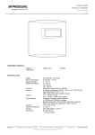
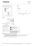
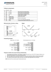
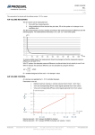
Coding by using jumpers
0…10 V *
direct output to the cooling actuator
10…0 V
reverse output to the cooling actuator
0…10 V *
direct output to the heating actuator
10…0 V
reverse output to the heating actuator
PI *
control mode (PI controller)
P
control mode (P controller)
S1
S2
S3
3-point motor
actuator type selection
S4
thermal actuator *
1-stage cooling
number of cooling stages
S5
2-stage cooling *
I first
Y1 (0…10 V) cooling output works first
II first *
3-point/thermal actuator cooling output works first
S6
* = Factory setting
Wiring terminals, trimmers, coding
Stages
Connecting actuators
3-point and 0…10 V actuators
Produal Oy
Keltakalliontie 18, 48770 Kotka FINLAND
Thermal actuators and 0..10 V actuators
Tel: +358-5-230 9200 / Fax: +358-5-230 9210
Information is subject to change without prior notice.
[email protected]
www.produal.com
USER GUIDE
HLS 33
2 (2)
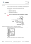
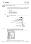
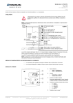
Things to be taken into account during commissioning
1.
While changing trimmer positions or other settings, the setting values are shown on the HLS 33-N display (a display can be
connected also temporarily for the commissioning procedure)
2.
When the 3-point output is in the control area edge, the output is driven against the edge for 5 seconds every 5 minutes
3.
After a power failure, the 3-point output is driven for 1,5 x running time to close the valve and to determine the position
4.
If the cooling is prevented but the cooling is still needed, the green indicator light flashes every 30 seconds
NOTE: Block the air flow coming through the cable protection tubes.
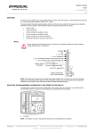
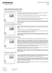
Changing the set point potentiometer midpoint
The potentiometer midpoint range is 18…24 °C.
NOTE: It is useful to fit a display to HLS 33 models during the potentiometer midpoint setting. The display can be removed after the setting is
done.
1.
Make sure the device is connected to supply voltage.
2.
Remove the device cover.
3.
Turn the potentiometer to the position where the 21 °C set point is wanted to be.
4.
Connect the soldering points shown on the figure for a while.
Use e.g. a screw driver for connecting.
Do not touch any other components
The midpoint changing is successful when 21.0 °C starts flashing on the display.
Produal Oy
Keltakalliontie 18, 48770 Kotka FINLAND
Tel: +358-5-230 9200 / Fax: +358-5-230 9210
Information is subject to change without prior notice.
[email protected]
www.produal.com