1
Reference GL/eDEP/USER/1/1.13
eDEP
eDEP
User Guide
eDEP
Page 1 of 63
Reference GL/eDEP/USER/1/1.13
eDEP
Table Of Contents
1
Introduction..................................................................................................................................... 3
1.1
References............................................................................................................................... 3
1.2
Document Change History...................................................................................................... 3
1.3
Abbreviations.......................................................................................................................... 5
2
Platform Overview.......................................................................................................................... 6
3
Platform & Tools Installation ......................................................................................................... 8
4
Delivery structure............................................................................................................................ 9
5
6
7
8
4.1
CVS Structure ......................................................................................................................... 9
4.2
Continuus Structure ................................................................................................................ 9
edep resource files......................................................................................................................... 10
5.1
Introduction........................................................................................................................... 10
5.2
Command Line Arguments................................................................................................... 12
5.3
Resource List ........................................................................................................................ 12
5.4
Colours & Fonts.................................................................................................................... 32
5.5
COLOUR PALETTES.......................................................................................................... 32
5.6
Typical Resource FIle Structure ........................................................................................... 32
edep scenario files......................................................................................................................... 33
6.1
Airspace File ......................................................................................................................... 33
6.2
Traffic file ............................................................................................................................. 42
6.3
AIRCRAFT PERFORMANCE FILE................................................................................... 47
6.4
map file ................................................................................................................................. 49
running eDep applications ............................................................................................................ 51
7.1
Introduction........................................................................................................................... 51
7.2
Pre-Requisites ....................................................................................................................... 51
7.3
MONO-VM EXAMPLES..................................................................................................... 53
7.4
distributed application EXAMPLE....................................................................................... 53
7.5
VALIDATION SCENARIO EXAMPLE ............................................................................. 54
7.6
recording, replay and the Monitor......................................................................................... 54
7.7
EEC Applications.................................................................................................................. 56
Java web start................................................................................................................................ 59
8.1
installation............................................................................................................................. 59
8.2
General.................................................................................................................................. 59
8.3
Java obfuscation.................................................................................................................... 61
Page 2 of 63
Reference GL/eDEP/USER/1/1.13
eDEP
1
INTRODUCTION
The aim of this document is to assist eDEP users with the activities of platform installation,
configuration and launching.
For more information concerning the platform design the reader should address either the Architecture
Design Document (ADD) or the Detailed Design Document (DDD).
1.1
REFERENCES
Ref
Title
Doc Reference
Authors
Date
1
eDEP Architecture Design Doc.
GL/eDEP/ADD/1 V1.8
M. Vere
March 2003
2
eDEP GSDK Detailed Design
1.5
M.Vere
October 2002
3
eDEP ATC Detailed Design
GL/eDEP/DDD/1/1.9
M. Vere
March 2003
4
5
6
7
1.2
IPAS ACE 2004B External
Interface
Requirement
Specification.
eDEP_SPD_ADD.doc (the Sector
Package Demonstrator ADD)
eDEP_FlightLeg.doc
eDEP Software Configuration
Management Plan
version 6.1
1 March 2004
Version 1.2
S.Owen
Latest
GL/eDEP/FL/001
S. Owen
Latest
GL/eDEP/TN/1/1.0
M. Humphrey
May 2007
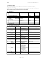
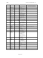
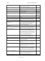
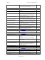
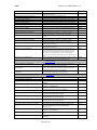
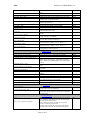
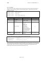
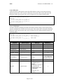
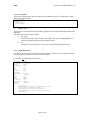
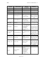
DOCUMENT CHANGE HISTORY
Release
Author
Release Date Release Description
0.50
Graffica (Vere) 25th Aug 2005
0.51
Graffica
(various)
0.52
Graffica
10th Jan 2006
(Owen)
Graffica (Vere) 16th Jan 2006
2nd Jan 2006
Modifications (sections affected
and relevant information)
Added resource to allow Section 5.3.1.6
STCA filtering on CFL.
Added various resources.
Improved ILS description.
Added additional flight plan
attributes.
Added SPD resources
Sections 5.3.1.4, 5.3.1.6, 5.3.1.7, 5.3.1.9
Section 6.1.8
Section 6.2.1
Sections 5.3.1.6, 5.3.1.12, 5.3.1.7
0.53
Graffica
(various)
25th April
0.54
Graffica
(various)
Graffica
(various)
Graffica
(Humphrey)
Graffica
(Humphrey)
Graffica
(Owen)
Graffica
(Owen)
5th July 2006
Added
new resources
relating to changes for
FASTI.
Various resources
added/modified. MAFF
conversion added.
Various resources added.
26th Oct 2006
Various resources added.
Section 5.3.1.4
27th Nov 2006
Added recording stream
reset resource.
Section 5.3.1.2
14th Dec 2006
Added LOA to airspace file
description.
Section 6.1.5
28Feb2007
Add TP resource for
multiple TP servers.
Section 5.3.1.6
28Feb2007
Added FM resource
FM.XFL_MODEL.TOCBOD
.TOLERANCE
Added CFMU-eDEP
converter resources.
Sections 5.3.1.6
Graffica(Rawli
ngs)
Graffica
(Kirkwood)
5Apr2007
Various graphics resources
added.
Section 5.3.1.4
11 Apr 2007
Updated ARTAS resources
Section 5.3.1.6
0.52
0.55
0.56
0.57
0.58
0.59
0.60
0.61
Page 3 of 63
Sections 5.3.1.4 and 5.3.1.7
Section 5.3.1.6, 5.3.1.7, 5.3.1.9, 7.7.1
Section 5.1.5, 5.3.1.6, 5.3.1.7, 5.3.1.9
Reference GL/eDEP/USER/1/1.13
eDEP
Release
0.62
0.63
Author
Release Date Release Description
Graffica
(Hargreaves)
Graffica (Vere)
16th Apil 2007 Added resource descriptions
0.64
Graffica
(Humphrey)
0.65
Graffica
(Stainton)
Graffica
(OWEN)
0.66
0.67
0.68
1.0
1.1
1.2
1.3
1.4
1.5
1.6
1.7
1.8
1.9
1.10
1.11
1.12
1.13
Graffica
(Hargreaves)
Graffica
(Kirkwood)
for filtering.
rd
23 Apil 2007 Added resource for SIL
4th May 2007
committed PEL display
Removed sections now
contained in SCMP
29th May 2007 Added stca resource to select
track sources
07 Jul 2007 Remove REC and CFMU
07 August 2007
resources which are now in
the eDEP_EEC_DDD
Added resource descriptions
for height filter range
10 August 2007 Added
IAS.GENERATE_DAP
resource.
Version number change to
common Graffica standard
Modifications (sections affected
and relevant information)
Section 5.3.1.7
Section 5.3.1.7
Sections 3 and 4.2.
Section 5.3.1.6
Section 5.3
Section 5.3.1.4
Section 5.3.1.6
Graffica
(Thom)
Graffica
(OWEN)
Graffica
(OWEN)
13th August
2007
14 Nov 2007 Added resource for PVD
N/A
10 Dec 2007 Changed resource name
Section 5.3.1.7
Graffica
(Rawlings)
Graffica
(OWEN)
Graffica
(OWEN)
21 Dec 2007
Section 5.3.1.4
SHOW_LAND_WHEN_NU
LL to
SHOW_FOR_NULL_COP
Added resources named
GSDK.AWS.LINK…
Section 5.3.1.7
24 Jan 2008
Updated CS (coordination
resources.
Sections 5.3.1.5 and 5.3.1.6
29 Feb 2008
CORE COORDINATION
BUG FIXES
CS and UCWP resources
Added GSDK secure
socket resources.
Section 5.3.1.6
CORE_GSDK_AWSPATHDE
TAILS_IMPROVEMENT:
Modified resources for
PVD.TRAIL
Added resources PVD
HDG_VECTOR_WIDTH
and
HIGHLIGHTED_HDG_VEC
TOR_WIDTH
Added a resource for single
button re-centre.
Section 5.3.1.7
Graffica
(VERE)
Graffica
(OWEN)
15 April 2008
Graffica
(VERE)
Graffica
(VERE)
13 August 2008
Graffica
(OWEN)
Graffica
(OWEN)
19 Aug 2008
Graffica
(OWEN)
Graffica
(OWEN)
25 June 2008
Section 5.3.1.3
5.3.1.4
15 August 2008 Added a resource to enable 5.3.1.3
20 Oct 2008
the middleware for remote
network distribution,
ENABLE_REMOTE_DISCOV
ERY.
Updated FM, MTCD and CS
resources
Section 5.3.1.6
Section 5.3.1.9
22 Oct 2008
Added a PWP resource for
auto PACK when a flight is
deleted
Added resources for MTCD
14 Jan 2009
Added resources for PPD
Section 5.3.1.7
Page 4 of 63
Section 5.3.1.6
Reference GL/eDEP/USER/1/1.13
eDEP
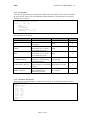
1.3
ABBREVIATIONS
Abbreviation
CWP
IDE
JRE
JVM
PPD
PWP
SDK
AVT
Meaning
Controller Working Position
Integrated Development Environment
Java Runtime Environment
Java Virtual Machine
Predicted Problem Display
Pilot Working Position
Software Development Kit
ADS-B and TIS-B Validation Testbed.
Page 5 of 63
Reference GL/eDEP/USER/1/1.13
eDEP
2
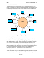
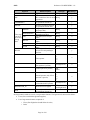
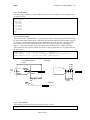
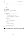
PLATFORM OVERVIEW
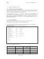
The following diagram shows the principal Edep component objects and their associations in the
platform. Each of the data flows is described in the following paragraphs, identifying the data content
of each terminator on the diagram. The labels attached to each data flow indicate the nature of the
information being between Edep and the terminator.
Traffic
File
Control
Console
console time
change requests
text based traffic
definition
time
updates
Airspac
e File
text based
airspace definition
inputs through
graphical devices
Graphics
Displays
formatted
mapping data
eDEP
Map
Files
graphics display
output
security
policy
named resource
values
Java Security
Policy Files
serialised
output data
Resource
s Files
Logging
and
Figure 2-1 Edep Context Diagram
2.1.1 Resources Files
The resources files provide a mechanism to load named resource values into a static resource
database, which can be accessed directly from any object running within a single Java Virtual
Machine. The values can be the simple types Boolean, String, Integer or Real, or a complex list
structure, with arbitrary sequences of values, arranged into lists. The lists can be nested to an arbitrary
depth, and define an arbitrary structure. The file is referenced from the command line –r parameter. A
single resource file may also load other files referenced from a designated file, using a #LOAD
directive within the file.
These resource values are used to configure the source and level of diagnostic output, the required set
of components to run (including the actual component class to use and the corresponding component
names). It also defines the fonts, and logical and physical colours to use in the graphical components,
the specific class implementations to use for key component interfaces, and the layout and
configuration of graphical items. The resources files are further detailed in section 5.
2.1.2 Map Files
The ATC application may need access to map information, in particular coastline, but also terrain and
feature definitions. The map file provides this information in a generic form, allowing coastline,
contours, area features, linear features and point features to be defined. The default map provided is
Page 6 of 63
Reference GL/eDEP/USER/1/1.13
eDEP
for the UK coastline only. Further information can be found in the NIMA web site at
http://www.nima.mil. The map files are explained in section 6.3.
2.1.3 Airspace File
This file provides a free formatted text description of the airspace, and contains airspace feature
definitions, which include sectors, units, airspace fixes, standard routes, SIDs, STARs, airports,
runways and letters of agreement. The airspace file syntax is explained in section 6.1
2.1.4 Traffic File
The traffic file provides a free formatted text description of the set of flight plans required to run with
the platform. These plans define the initial flight plans (IFPL) for the flights associated with the
named callsigns. These plans use information defined in the airspace file to create the plans, using
either standard routes, SIDs and STARs, or using user defined routes, defining paths through any set
of fixes, or indeed flying to anonymous points in space identified simply by a latitude and a longitude.
Each plan can also define information about the flight including its RFL and aircraft type information.
The traffic file syntax is elaborated in section 6.2.
2.1.5 Java Security Policy Files
Java security policy files need to be defined to enable the Java RMI to clear its compulsory security
checks when it initialises, and when information is passed through an RMI method invocation. For
standalone purposes, the file will simply grant full access rights to the process. If running across a
network or over the Internet, it might be necessary to allow access only to the required data sources.
2.1.6 Graphics Displays
When running an experiment, the graphics displays will typically be provided by 7ctioned7ion CWP
components. The graphics may be output to MS-Windows based displays, or to Unix/Linux based XWindow based displays, depending on the host operating system being used, and the corresponding
Java Virtual Machine (JVM) being run.
2.1.7 Console
The console provides a simple input and display device to monitor and control the progress of the
simulation. The baseline version simply controls the rate of flow of time, and provides pause and
resume functions.
2.1.8 Logging and Analysis
The logging and analysis facilities will allow inter-component messages to be logged, along with
graphics events, and other I/O performed by the platform. This facility is to be completed.
Page 7 of 63
Reference GL/eDEP/USER/1/1.13
eDEP
3
PLATFORM & TOOLS INSTALLATION
This section has been superseded by the ‘Development Environment’ section of the eDEP Software
Configuration Management Plan (SCMP) [Ref 7].
Page 8 of 63
Reference GL/eDEP/USER/1/1.13
eDEP
4
DELIVERY STRUCTURE
The Edep platform is delivered in one of two forms – as a team developer project, or as a restricted
developer project. The main difference between the two deliveries is that in the former the GSDK is
delivered as source code, whilst in the latter it is delivered as a compiled jar file.
4.1 CVS STRUCTURE
The Graffica developers work with the following CVS-driven directory structure.
The configured column indicates which items are configured and must be placed under configuration
control.
Directory
Configured
Description
<home>
.project and .classpath The Eclipse project files.
<home>/products
Contains derived products such as jar files, 9ctione, class
files etc
<home>/scripts
Contains useful script files (.bat .csh .ant) including
Edep.xml used to generate the RMI stubs.
<home>/TOOLS
Contains auxiliary software such as JAXP (DOM) and
Retroguard.
<home>/ATC
The ATC module
<home>/ATC/scripts
The script files (e.g. launch files) related to the ATC
module
<home>/ATC/src
The source code related to the ATC module This includes
• atc – the set of reusable ATC components
• atcapp – the main program classes and scenario files
• test – the atc specific test software
<home>/GSDK
The GSDK library module, containing src and scripts
subdirectories.
<home>/ASMT
The various client applications built upon the Edep
<home>/CORA2
platform.
<home>/TCAS
<home>/EEC
The EEC module, containing EEC integration code (e.g.
connections to IPAS and STORIA)
4.2 CONTINUUS STRUCTURE
This sub-section has been superseded by the eDEP Software Configuration Management Plan
(SCMP) [Ref 7], namely the ‘EEC Onsite Activities’ section for the Synergy CM (previously
Continuus) project organisation, and the ‘Development Environment’ section for how to work with
these.
Page 9 of 63
Reference GL/eDEP/USER/1/1.13
eDEP
5
5.1
EDEP RESOURCE FILES
INTRODUCTION
5.1.1 Overview
The GSDK provides a central mechanism to provide named resource values to participating
applications. These resources are similar to Unix shell variables, or Java properties. The Resources
class provides a set of static methods to access the required resource items. These items can define the
primitive values Boolean, real, integer or String. In addition, arbitrary lists of objects can be created,
and can be laid out in the file using free format text. Resource names must start with an alphabetic
character and may contain any alphanumeric or underscore ‘_’ or dollar ‘$’ or period ‘.’. By
convention, resource names can be grouped logically by using the period character to create more
meaningful names.
Resources are initialised at start-up by specifying the resource file name on the command line, by
using the –r <filename> option. Specific resource values may also be set directly via the command
line, using the –p <resource name> <resource value> option.
5.1.2
Resource Value Syntax
5.1.2.1 String
Strings can be introduced as a single word (if it can be read as a single token), or terminated with
double quotation marks “…” to include white space or special characters.
5.1.2.2 Boolean
A Boolean value is introduced with the reserved name tokens TRUE, true, FALSE or false.
5.1.2.3 Numeric
Numeric values are read as double precision values, but stored as integer values if the number has an
equivalent value to an integer.
5.1.2.4 Lists
List elements are delimited commas or white space and terminated with round brackets ‘(‘ and ‘)’.
These lists may be homogeneous (all items of the same type) or heterogeneous (a mixture of items
including nested lists to an arbitrary depth).
5.1.2.5 Comments
Double slash // comments are accepted in resource files.
5.1.3 Combining Resource values From Existing Definitions
Resource values defined in the file can be constructed by combining existing resource name values
with new text items to form a new value. The items are de-referenced by prefixing the resource name
with a ‘$’ character, and combined using a ‘&’ character. Thus the following item definitions:
HOME c:/users/GSDK/
DAT “.dat”
SCENARIO $HOME & “example/test_scenario” & DAT
Will produce the following resource value:
SCENARIO = c:/users/GSDK/example/test_scenario.dat
Page 10 of 63
Reference GL/eDEP/USER/1/1.13
eDEP
5.1.4 Loading Nested Resource Files
The Resources file can read nested files, embedded in the file it is currently loading, introduced by the
“@LOAD” directive. This directive is followed by a file path name, which can include existing
resource strings.
@LOAD “applications/data/scenario.dat”
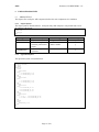
5.1.5 Manipulating Resource Files
The user can manipulate existing list resources by using the special operators, @APPEND, @JOIN,
@REMOVE and @MERGE. The operators respectively append a new item to a list (the item itself
can be a list), join two lists together, remove an item from a list, merge an item into a list (a simple
pattern match is employed to match the contents of the remove/merge property to the first matching
element in the list). Examples of their use are given below:
TEST ( A B C )
@APPEND D
@JOIN ( E F )
@MERGE G
@MERGE A
@REMOVE D
Result (
(
(
(
(
(
A
A
A
A
A
A
B
B
B
B
B
B
C
C
C
C
C
C
)
D
D
D
D
E
)
E
E
E
F
F
F
F
G
)
G )
G )
)
Note that any resource values can be overridden with new values simply by resetting the resource
value.
5.1.6 Resource File Locations
The Edep platform resource files are located using the Java SDK resources mechanism. This Java
mechanism allows resource filenames to be specified in a similar fashion to package Imports (i.e.
simple pathnames independent of the filesystem).
For example, packaged within the Edep delivery, under the <Edep Home>/ATC/src/atcapp
directory are a number of example resource files. As far as the SDK resource loader is concerned the
path of such files is “atcapp/”.
More specifically, the SDK with search through all directories and jar files listed within the
CLASSPATH variable in order to locate a resource file.
When using IDE tools such as Jbuilder and Eclipse the source (.Java) code is kept separate from the
compiled (.class) code. Obviously, when running applications the CLASSPATH refers to the classes
directory and not the source directory. Therefore these IDE tools will automatically copy all resource
files1 into this classes directory before running.
5.1.7 Reserved Resource Names
The resources file also defines a small number of reserved resource names, as indicated in the table
below.
Resource Name
LOGICAL_COLOURS
PHYSICAL_COLOURS
FONTS
Description
User defined list of named colours mapped to an item name.
User defined list of RGB values identifying physical colours.
User defined list of font name strings.
5.1.8 Scoped Resource Names & Overloading
Resources names can be complex, build up from ‘dot’ separated words. For example,
1
Eclipse will treat all non Java files as resources – hence they will be copied. JBuilder has to be to be
configured via the properties option to copy certain file types.
Page 11 of 63
Reference GL/eDEP/USER/1/1.13
eDEP
GSDK.MIDDLEWARE.OPTIMISE_COLLOCATION FALSE
CWP1.GSDK.MIDDLEWARE.OPTIMISE_COLLOCATION TRUE
The first element of the scoped resource is invariably the component name. This is often used to
provide a form of resource overloading. That is, when looking up a resource value “x.y”, the
platform will first attempt to locate a resource named “<component>.x.y” followed by “x.y”.
This obviously allows resource values to be set in a general fashion and then overloaded for a
particular component.
5.1.9 System Start up
During application launch, the Edep platform will automatically attempt to load a file
atcapp/resources/defaults.gsdk. This file is intended to contain system-wide defaults that
apply to all applications.
The developer may also cause the platform to load a specific resource file. This is done via the
command line option –r <resource file name>.
5.2 COMMAND LINE ARGUMENTS
The following command line arguments are recognised by Edep:
ARGUMENT
PURPOSE
-r <resource file>
Specifies the resource file to be loaded at start-up
-p <resource name> <resource value>
Allows specific resource values to be explicitly set via
the command line
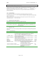
5.3 RESOURCE LIST
This section lists the resources currently available to the developer for tailoring the Edep platform
behaviour.
5.3.1.1
General Resources
Resource
COMPONENTS
Description
The list of components to be instantiated within the VM. This
list contains elements of the form (component-class componentname). For example, COMPONENTS( (atc.ts.TS TS) )
<c>.DEBUG_APP<c>
Boolean flag indicating if Debug is active within the context of
the given component’s thread.
DEBUG_UNKNOWN Boolean flag indicating if debug is active within the context of
unknown threads (e.g. RMI threads).
DEBUG
Global flag for disabling debug everywhere when set to false.
WARNING
Boolean flag defining if warning messages should be output.
MESSAGE
Boolean flag defining if info messages should be output.
<component>.SCENARIO
The Entity scenario file used to populate the
components database on startup.
<component>.DYNAMIC_SCENARIO
The monitored dynamic scenario directory
<component>.DYNAMIC_SCENARIO_UPDATE
The default speed for polling of the
monitored scenario directory, in
milliseconds.
Page 12 of 63
Default
FALSE
FALSE
FALSE
TRUE
TRUE
N/a
N/a
1000
Reference GL/eDEP/USER/1/1.13
eDEP
Page 13 of 63
Reference GL/eDEP/USER/1/1.13
eDEP
5.3.1.2 Recording and Replay resources
The following resources are available for recording and replay. Refer to section 0 for more
information.
Note: in the current release of the Edep platform these resource options are normally associated with
CWP components.
Resource
<component>.RECORD_MODE
<component>.RECORD_FILE
<component>.ORDER_RECORD_FILE
REPLAY.ORDER_RECORD_INDEX
GSDK.RECORDING.STREAM_RESET_INTERVAL
5.3.1.3
Description
Value is either RECORD, REPLAY or NONE
When RECORDing this value defines a
filename into which all network messages are
recorded. For example,
/edep/src/atcapp/recording/cwp1.log” When
REPLAYing this value a Java resource from
which replay data is retrieved. For example,
“atcapp/recording/cwp1.log”
Only used in RECORDing mode. Defines the
file into which all significant scenario events
(e.g. controller orders) are recorded. For
example,
“/ATC/src/atcapp/recording/cwp1_orders.log”
Only used in REPLAY mode. Defines a Java
resource file which itself lists all of the
individual order record files to load
The number of events to write to the output
stream between each call to reset() (to avoid
memory leaking).
Default
NONE
100
Middleware Resources
Resource
GSDK.MIDDLEWARE.DISCOVERY_DEFAULT_TIMEOUT
GSDK.MIDDLEWARE.DISCOVERY_HOST
GSDK.MIDDLEWARE.DISCOVERY_PORT
GSDK.MIDDLEWARE.EVENT_DISPATCHING_THREADPOOL_SIZE
GSDK.MIDDLEWARE.MULTITHREAD_EVENT_DISPATCHING
GSDK.MIDDLEWARE.OPTIMISE_COLLOCATION
GSDK.MIDDLEWARE.OPTIMISE_EVENT_MARSHALLING
GSDK.MIDDLEWARE.OPTIMISE_ONEWAY_CALLS
GSDK.MIDDLEWARE.ENABLE_REMOTE_DISCOVERY
Page 14 of 63
Description
Defines the time in seconds that the
discovery service will wait before
abandoning a lookup.
The hostname of the machine running
the Edep discovery service (contained
within the simulation Engine)
The port used by the RMI registry
(found within the discovery service)
Thread Pool size for multi threaded
event dispatching
Determines if an event can be
distributed to several clients in parallel
If active, then the use of RMI is
suspended between objects within the
same VM (i.e. no serialization
overhead)
If set then events are pre-marshalled
before being dispatched to clients.
This is an important 14ctioned14ion
when the number of clients is large.
Provides a CORBA-like oneway
semantic for remote methods which
have a void return type.
When set to true, the discovery server
is started as a separate process
enabling distribution of a system on a
network of machines. When false the
system runs standalone with discovery
Default
1099
5
FALSE
TRUE
FALSE
FALSE
FALSE
Reference GL/eDEP/USER/1/1.13
eDEP
Resource
GSDK.MIDDLEWARE.RUN_DISCOVERY_SERVER
GSDK.MIDDLEWARE.SSL.DEPLOY_SECURITY
GSDK.MIDDLEWARE.SSL.KEYSTORE_FILEPATH
GSDK.MIDDLEWARE.SSL.KEYSTORE_PASSPHRASE
Page 15 of 63
Description
as a thread inside the VM.
Determines if the discovery server is
to be started or not on this VM. This is
usually set to false when running
internet demos.
Specifies whether the middleware
should deploy the secure sockets layer
(SSL) based RMI.
Defines the file path to the key store
containing the certificates to use to
create the SSL sockets.
Defines the “pass phrase” to access
the key store certificates.
Default
TRUE
FALSE
Null
Null
Reference GL/eDEP/USER/1/1.13
eDEP
5.3.1.4
Graphics Resources
Resource
Description
Default
CURSOR_SIZE
1=Default cursor (mouse pointer)
2=more visible cursor,
3=larger, more visible cursor.
1
DEBUG.AWS.PATCH
FONTS
GSDK.AWS.OPTIMISE_REDRAW
Defines the list of fonts to use
Determines whether graphics optimisation should be used.
Options are NONE and SINGLE_RECTANGLE
NONE
GSDK.AWS.UPDATE_THRESHOLD
Defines the maximum number of dirty redraw rectangles
allowed before a full redraw is 16ctioned
-1 (i.e. unlimited)
GSDK.AWS.USE_VOLATILE_IMAGES
Defines if J2SE 1.4 support for Volatile Images may be
used
Defines if Volatile Images are to be used throughout the
graphics display. For use with non-transparent displays
only.
Defines the heading number format. By default 3 digits are
output for the heading value.
Defines the range number format. By default 3 digits filled
with spaces are output for the range value.
Defines the graduation step value used when calculating the
heading value. By default a value of 5 is used. Setting the
value to 1 prevents the rounding of the heading value
allowing a number of decimal places to be specified in the
HEADING_FORMAT_CHAR resource item.
Defines a sensitive margin in pixels around a menu. It is
used to trigger a menu destruction if the corresponding
GSDK.AWS.MENU.DESTROY_ON_EXIT resource.
If set true, destroys menu when cursor is outside of
bounding margin.
If true destroys menu on mouse button 3 press
TRUE
GSDK.AWS.FULL_VOLATILE_IMAGES
GSDK.AWS.LINK.HEADING_FORMAT_CH
ARS
GSDK.AWS.LINK.RANGE_FORMAT_CHAR
S
GSDK.AWS.LINK.HEADING_GRADUATIO
N
GSDK.AWS.MENU.VERTICAL_MARGIN
and
GSDK.AWS.MENU.HORIZONTAL_MARGIN
GSDK.AWS.MENU.DESTROY_ON_EXIT
GSDK.AWS.MENU.DESTROY_ON_BUTTON
3
GSDK.RANGERING.FREQ
GSDK.REGION.LANE.AIRLANE_WIDTH
GSDK.SWING_GRAPHICS_UPDATE_RATE
GSDK.REPORT.HANDLERS
GSDK.REPORT.LOGFILE
GSDK.REPORT.TIMESTAMP
GSDK.REPORT.TIMFORMAT
GSDK.AWS.ZOOM_TO_MOUSE
GSDK.AWS.USE_CENTRE_BUTTON_RECE
NTRE
GSDK.AWS.USE_CENTRE_BUTTON_PAN
GSDK.AWS.PAN_SCALE_FACTOR
GSDK.MAXIMUM_TRAIL_HISTORY
GSDK.EXTENDED_RANGE_AND_BEARIN
G
GSDK.SPEED_FILTER_LOWER_BOUND
GSDK.SPEED_FILTER_UPPER_BOUND
GSDK.NUMBER_OF_SPEED_VECTOR_BUT
TONS
GSDK.SPEED_VECTOR_BUTTONS
GSDK.NUMBER_OF_TRACK_HISTORY_BU
TTONS
GSDK.TRACK_HISTORY_BUTTONS
IMAGES
LABEL.DEBUG
LOGICAL_COLOURS
PHYSICAL_COLOURS
TRANSPARENCY
PVD.NORMAL_COLOUR.FILL_SOLID
PVD.RTB.EXTENDED_RADAR_TOOLBOX
The frequency at which range rings are drawn.
Airlane width in Nautical Miles. This is only used when
running in non-transparent mode. N.b. 1Nm = 1852 metres.
Time in milliseconds between each redraw check
A list of report handler classes. The report handler objects
shall be generated from this list.
The name of the reporter log file to be used with the
FileReportHandler object.
The time stamp to append to the log file.
The format of the time in the time stamp using the Java
SimpleDateFormat class.
Zoom control using mouse wheel.
Map centre control using mouse centre button. Overridden
by USE_CENTRE_BUTTON_PAN resource described
below.
Pan control using mouse centre button
Pan scale factor
Length of trail history
Extended range and bearing tool showing range and bearing
readout at both ends of the line.
Lower range value for speed filter
Upper range value for speed filter
Number of speed vector buttons in extended radar toolbox
FALSE
000
###
5
10 pixels and 10 pixels
False
True
5
18520
20
Empty list
“edep_log”
False
hh.mm.ss_ddMMMyyyy
TRUE
TRUE
TRUE
4
15
FALSE
0
100
5
Speed vector button label values in the form of a list.
Number of track history buttons
None
5
Track history button label values in the form of a list
Directory where application images are kept.
Used by several graphical applications to display extra
debug information in graphical labels
Defines the list of logical colours.
Defines the list of physical colours.
Boolean flag determining if overlay transparencies are to be
used
Fills polygons with solid colour in non-transparent mode.
Can be used to give impression of transparent colour.
Increased number of trail history buttons in radar tool box
None
Atcapp/resources/images
FALSE
Page 16 of 63
FALSE
FALSE
FALSE
Reference GL/eDEP/USER/1/1.13
eDEP
RADAR_TOOLBOX.HEIGHT_FILTER.LOW
ER
RADAR_TOOLBOX.HEIGHT_FILTER.UPPE
R
SCREENMANAGER
PLUGIN.CWP_SCREEN_MANAGER
5.3.1.5
Lower range for the height filter
0
Upper range for the height filter
600
Defines the Screenmanager to be used – this will be
replaced by the PLUGIN.CWP_SCREEN_MANAGER
individual managers in future.
Defines the screenmanager Plugins components to be used.
These are defined in interface / implementation pairs.
PpdManagerImpl
PvdManagerImpl
VawManagerImpl
EATMPFlightLegManag
er & AsasManagerImpl
General ATC resources
Resource
Description
CPDLCACM.STD, CPDLCALC.STD
ATC.LAST_VALID_LOWER_FLIGHT_LEVEL
ATC.RVSM
CLOCK.STARTTIME
Defines the datalink state machines.
CLOCK.STOPTIME
CLOCK. SYNCHRONIZED_TO_UTC
PROJECTION.CENTRE.LATITUDE
PROJECTION.CENTRE.LONGITUDE
Determines if RVSM separations are to be used
Defines the clock start time within a quoted string. The value can be of the
form “HH:MM:SS” or “dd/MM/yy@HH:mm:ss”
Defines the time at which the platform should shutdown. If no value is
specified, the platform will continue to run ad infinitum.
When set to true the simulation start time is set to the system time and the
simulation is started as soon as the TS component is started. The play,
pause and fast-forward buttons on the console are disabled when in this
mode. If the CLOCK.SYNCHRONIZED_TO_UTC resource is set to
true, the CLOCK.STARTTIME is ignored.
Defines the centre of projection (in degrees) for the application. The
values are simple floating-point numbers.
Note: this value should be identical for all components forming part of the
same Edep application.
PROJECTOR.CLASS
The coordinate conversion algorithm.
CONSTRAINT.CLASS
Defines the implementation class for the Constraint interface. The default
value is gsdk.trajectory.ConstraintImpl
Defines the implementation class for the Trajectory interface. The default
value is gsdk.trajectory.TrajectoryImpl
Defines the implementation class for the Waypoint interface. The default
value is gsdk.trajectory.WaypointImpl
TRAJECTORY.CLASS
WAYPOINT.CLASS
Page 17 of 63
Default
true
00:00:00
None.
False
52.0 0.0
Gsdk.geometry
.Lambert
Reference GL/eDEP/USER/1/1.13
eDEP
5.3.1.6
Core ATC Component Resources
Resource
Description
Default
ACSG Component
CONNECTED
Sets the TCAS source to ACAS server if true, scripted if
false.
The following resources are only required when CONNECTED=TRUE
ACS_PORT_MTRK
The port on which to send to the ACS for MTRK messages.
ACS_PORT_NOTIF
The port on which to send to the ACS for NOTIF messages.
LOCAL_PORT
The port on the local machine to listen to for ACS Ras
messages.
The following resources are only required when CONNECTED=FALSE
SCENARIO_READER
The Scenario Reader for TCAS Entities.
(eg. Atcx.acsg.server.ACSGScenarioReaderImpl)
SCENARIO
The TCAS Script.
DATALINK_UPDATE_INTERVAL
The frequency, in seconds, at which TCAS advisories should
be reported in Datalink mode.
FALSE
8010
8001
8011
1.0
ADSB Component
REPORT_CAT21
UDP.FORWARDING_CAT21_CONNECTION
S
UDP.FORWARDING_CAT21
UDP.FORWARDING_CAT21_DEBUG
UDP.FORWARDING_CAT244_CONNECTIO
NS
UDP.FORWARDING_CAT244
UDP.FORWARDING_CAT244_DEBUG
SMART.UDP.CONNECTIONS
SMART.UDP.ENABLED
UDP.MESSAGE_TYPE
UDP.READ_SIZE
STORE_HISTORY
BUFFER_INTERVAL
Sets debug report messages for CAT21 messages
Defines the external UDP channels to forward ADSB
Category 21 messages to.
Enables forwarding of ASTERIX Category 21 messages via
UDP.
Sets forwarding debug output for UDP forwarding of
Category 21 Asterix Messages.
Defines the names of the external UDP channels to forward
ADSB Category 244 messages to. Note: These channels
must be defined in SMART.UDP.CONNECTIONS resource.
Enables forwarding of ASTERIX Category 244 messages via
UDP.
Sets forwarding debug output for UDP forwarding of
Category 244 Asterix Messages.
The set of UDP connections from Edep/ADSB to SMART.
Also connections to external clients.
The SMART UDP connection is enabled.
The Java class defining the type of message (always Asterix)
Maximum UDP message size in bytes
The ADSB reports are stored in the ADSBHistory object if
this is set, otherwise only one report is stored.
Rate at which incoming UDP ADSB messages are
distributed.
FALSE
FALSE
FALSE
FALSE
FALSE
FALSE
4096
FALSE
1 (second)
Coordination Component
COORDINATION.ADVANCE_BOUNDARY_TIME
1800.0
unitName.COORDINATION.AUTOMATIC_ASSUME_
DELAY
Time, in seconds, from unit entry at which the ABI
(Advanced Boundary Information) is signalled to the next
unit – also called a NOTIFY message.
Time, in seconds, from unit entry at which inbound is
signalled to the next unit
Determines whether coordination requests should be
automatically accepted in a CWP of the given name.
Defines if all handovers should be automatically initiated and
accepted (ideal for demonstration modes)
For the automatic handover, the time in seconds after a flight
crosses the next Unit boundary that the handover will be
triggered.
For automatic handover, the time (seconds) after a flight has
been transferred into the local Unit that the ASSUME will be
triggered.
unitName.COORDINATION.AUTOMATIC_RESPO
NSE_DELAY
Time delay between a request and the response from an
unmanned unit, or automatically responding CWP.
20.0
COORDINATION.ACTIVATION_TIME
context.COORDINATION.AUTOMATIC_ACCEPTA
NCE
context..COORDINATION.AUTOMATIC_HANDOV
ER
unitName.COORDINATION.AUTOMATIC_TRANSFE
R_DELAY
Page 18 of 63
600.0
FALSE
FALSE
-60.0
60.0
Reference GL/eDEP/USER/1/1.13
eDEP
Whether the ATC Controller should be prompted to handover
the flight when leaving the local ATC Unit.
TRUE
COORDINATION.RELEASE_REMINDER
If the previous resource is true, the delay (seconds) before the
prompt should appear.
0.0
COORDINATION.RELEASE_REMINDER_DELAY
Whether the CS server may skip Units of a short traversal
duration.
FALSE
If the previous resource is TRUE, the traversal duration
(seconds) below which the ATC Unit will be skipped.
120
Whether non-standard Unit boundary conditions should be
negotiated with the downstream Unit when that Unit becomes
ACTIVATED.
Disable the CS server's automatic ACT and ABI messages,
and its Agreement TIMEOUT messages. Used by the AEG
gateway which needs simply to load the coordination state
coming from the ESCAPE CS server, which would conflict
with any action performed by the eDEP server.
Whether the UCWP should perform automtic CFL orders in
the stated unmanned Unit, or generally in all unmanned
Units.
FALSE
A definition of CFL orders to be given to flights on specified
routes after being ASSUMED in a particular unmanned ATC
Unit. (See the CS section in the eDEP_GRD_DDD for
details).
None
COORDINATION.COORDINATION.AUTO_SKIP.E
NABLED
COORDINATION.AUTO_SKIP.THRESHOLD
COORDINATION.RAP_ENABLED
COORDINATION.SERVER_AUTO_MESSAGES_D
ISABLED
UCWP.unitName.AUTO_GUIDANCE_ENABLED
or (2nd priority)
FALSE
TRUE
UCWP.AUTO_GUIDANCE_ENABLED
UCWP.ASSUME_CFLS
e.g. UCWP.ASSUME_CFLS (
( FE, 240, (EDDW,EDDH), IMMEDIATE)
)
COORDINATION.ROUTE_UNIT_AG
REEMENTS
where IMMEDIATE means give the CFL order on being
ASSUMED without waiting for the flight to leave the
CONCERNED Unit.
A resource for specifying the COP flight level for flights on
specified routes when entering a specified ATC Unit. (see
the CS section in the eDEP_GRD_DDD for details).
E.g.
None
COORDINATION.ROUTE_UNIT_AGREEMENTS
(
(HH,(EHAM,EHRD),*,240),
(HH,*,*,RFL),
)
Here, flights from EHAM and EHRD to any destination
should enter Unit HH at FL240. If this rule does not apply
then any flights entering HH should enter HH at their RFL.
COORDINATION.ROUTE_NO_GO_
UNITS
A resource for specifying that a particular ATC Unit should
not receive control of a flight that is on specified routes. (See
the CS section of the eDEP_GRD_DDD for details)
E.g.
COORDINATION.ROUTE_NO_GO_UNITS
(
(*,
EHAM, DD),
)
Here, flights going from any origin to EHAM should not ne
handed over to Unit DD which should be skipped from the
chain of control.
AIRSPACE Component
ASP.SCENARIO
ASP.SCENARIO_READER
Defines the resource file containing the airspace definition.
The resource path is relative (e.g.
atcapp/resources/airspace1.dat)
Defines which parser framework is to be used to read in the
scenario data. The value is normally
Page 19 of 63
None.
Reference GL/eDEP/USER/1/1.13
eDEP
ASP.MIDDLE_MARKER_POSITION
ASP.OUTER_MARKER_POSITION
ASP.LOCKON_WIDTH
ASP.LOCKON_HEIGHT
ASP.REDUCE_SPEED_DISTANCE
ASP.FINAL_APPROACH_SPEED
“gsdk.scenario.ScenarioReaderImpl”
The position, relative to an ILS Ladder at which the dotted
lockon box is drawn, for example a value of 6 means the
dotted lockon box is drawn on the 6th rung of the ladder,
counting away from the runway.
The length of the area (Nm) in which an aircraft can lockon,
defines the dotted box at the start of an ILS Ladder.
The width of the area (Nm) in which an aircraft can lockon,
defines the dotted box at the start of an ILS Ladder.
The maximum height (ft) an aircraft can lockon at.
The distance from the runway that the aircraft should reduce
speed in Nm.
Returns the final approach speed for a B744 in knots
8 Nm
13Nm
1Nm
3000ft
4Nm
150Knots
ACR (Performance) Component
ACR.SCENARIO_READER
ACR.SCENARIO
ACR. USE_OPERATIONAL_VALUES
Defines which parser framework is to be used to read in the
aircraft performance data. If the program is reading BADA
data with online conversion, this should be
“atc.performance.server.BadaScenarioReaderImpl”,
otherwise “gsdk.scenario.ScenarioReaderImpl”
Defines the file holding the aircraft performance data. If the
program is reading BADA data with online conversion, this
should be the types.dat file at the root of the BADA directory;
otherwise, this should be the Edep-formatted aircrafttypes.dat
file.
override the turn radius rate values to give constant turn rate
for all altitudes.
FALSE
ARTAS
ARTAS.<StreamID>.DEBUG_REPORT_CAT62
ARTAS.<StreamID>.DEBUG_REPORT_CAT32
ARTAS.<StreamID>.DEBUG_REPORT_CAT21
UDP.ENABLED
ARTAS.<StreamID>.FILTER_ON_ARTAS_UNITS
CONNECTIONS
UDP.READ_SIZE
CWP.RECEIVE_UNITS
UDP.MESSAGE_TYPE
ARTAS.<StreamID>.DSID_SIC
ARTAS.<StreamID>.DSID_SAC
ARTAS.<StreamID>.USER_NUMBER
ARTAS.<StreamID>.CENTRE
ARTAS.<StreamID>.POSITION
IAS.GENERATE_ENRICHMENT_REPORT
IAS.ENRICH_EVERY_REPORT
ARTAS.STATE_VECTOR_DEBUG
ARTAS.MISSED_TRACK_STALEOUT
ARTAS.UPDATE_RATE
Sets debug report messages for CAT62 messages
Sets debug report messages for CAT32 messages
Sets debug report messages for CAT21 messages
Set to true if UDP connections are required, including host
channel name, host name port.
Defines whether ARTAS unit should be used to filter
messages.
Defines the set of UDP connections required.
Maximum size of UDP message in bytes.
Units to receive data from Artas for.
The Java class defining the type of message (always Asterix)
The default data source identifier.
The default data source area.
The user number enrichment data.
The track source centre enrichment data.
The track source position enrichment data.
Enriches track data with ARTAS sourced data
Enrich every track with the additional ARTAS data.
Debug information for state vectors.
The number of tracks to miss before a track is staled out.
The speed that artas updates each track. (used to calculate stale out
time).
FALSE
FALSE
FALSE
FALSE
4096
0
0
0
FALSE
FALSE
FALSE
1
5
ASTERIX MESSAGES
ASTERIX.FIX_FSPEC_LENGTH
If set, Asterix message compound fields FSPEC fields are set
to a fixed maximum length. See
atc.asterixmessages.fields.compound.AbstractCompoundFiel
d.
false
DL (Datalink) Component
DL.ACL_TIMEOUT
DL.ACL_AUTOMATIC_RESPONSE_DELAY
DL.ACM_AUTOMATIC_RESPONSE_DELAY
The maximum time, in seconds, allowed for an ACL dialogue
before it is deemed to have timed out.
The delay before the Datalink server will auto-respond to an
Clearance request when no PWP is present.
The delay before the Datalink server will auto-respond to a
Page 20 of 63
15
10
10
Reference GL/eDEP/USER/1/1.13
eDEP
Handover request when no PWP is present.
IFPL Component
<IFPL>.ACTIVATION_DELTA
<IFPL>.FORCE_IMMEDIATE_ACTIVATION
<IFPL>.SCENARIO
<IFPL>.SCENARIO_READER
IFPL.START_TRAJECTORY_ID
Defines the activation delta time in seconds. Flight Plans will
be sent out this number of seconds before their official
activation time.
If set to TRUE then all IFPLs are activated immediately at
start up. This is useful for data preparation needs
Defines the resource file containing the airspace definition.
The resource path is relative (e.g.
atcapp/resources/airspace1.dat)
Defines which parser framework is to be used to read in the
scenario data. The value is normally
“gsdk.scenario.ScenarioReaderImpl”
The trajectory ID is an incrementing field stored in the
flightplan. It is set in flightplan order starting from this
value. It is used for PMs generation ADSBReports.
0.0
FALSE
1000
STCA Component
<STCA>.COVERAGE_ZONE.LAT1
<STCA>.COVERAGE_ZONE.LONG1
<STCA>.COVERAGE_ZONE.LAT2
<STCA>.COVERAGE_ZONE.LONG2
Defines the lat/long rectangle for which safety nets are
required.
<STCA>.LOOKAHEAD_TIME
<STCA>.SEPARATION_THRESHOLD
<STCA>.UPDATE_INTERVAL
VERTICAL_SEPARATION.NON_LEVEL_SUPPLE
MENT
<STCA>.SMOOTHING DELAY
The look ahead time in seconds
The horizontal separation threshold in nautical miles
The update interval in seconds
120.0
5.0
5
0
The STCA smoothing delay in milliseconds. The STCA
calculation algorithm can be delayed before updating: this
helps to smooth out overall system loading.
Flag used to select filtering of STCA according to expected
CFL stop-off level.
The maximum possible aircraft speed in metres/second. This
value determines the size of the STCA grid.
When set Area Proximity Warnings are generated and shown
in the CWP aircraft label and alert window. An area
proximity warning is generated when a flight enters a
restricted area.
The number of seconds ahead of a flight entering a military
sector that an Area Proximity Warning will be generated.
A list of classes that represent filters to be applied to pairs of
tracks to determine whether or not they should be included in
the STCA calculation.
2000
<STCA>.FILTER_ON_CFL
<STCA>.MAX_POSSIBLE_SPEED
<STCA>.GENERATE_APW
<STCA>.APW_LOOKAHEAD_TIME
<STCA>.TRACK_PAIR_FILTERS
e.g.
False
350.0
False
90
The pair of
classes in the
example on
the left are
used as
defaults.
STCA.TRACK_PAIR_FILTERS
("atc.stca.server.filters.MilitaryPai
rFilter",
"atc.stca.server.filters.SameSourceFi
lter")
These filters reject tracks that are both military or
which are not derived from the same source.
<STCA>.USE_TRACK_SOURCES
A list of strings that reference the Track sources that are to be
monitored by the STCA calculation. Normally a Track
created within the platform is has the source name
“DEFAULT”.
(“DEFAULT”
)
MTCD Component
MTCD.ENABLED
TRUE if the MTCD server is enabled for calculating conflicts
Page 21 of 63
TRUE
Reference GL/eDEP/USER/1/1.13
eDEP
<contextName>.MTCD.ENABLED
<contextName>.TRAJECTORY_TAG
<contextName>.CONFLICT.CLASS
<context.name>.CONFLICT.RISK_SETTER.CLASS
<<contextName >.LOOKAHEAD_TIME
<MTCD>.SEPARATION_THRESHOLD
< contextName
>.CONTEXTUAL_SEPARATION_THRESHOLD
< contextName >.UPDATE_INTERVAL
<MTCD>.RISK_UPPER_VERTICAL_SEPARATIO
N_THRESHOLD
<MTCD>.RISK_LOWER_VERTICAL_SEPARATIO
N_THRESHOLD
<MTCD>.USE_EXTENDED_RISK
<MTCD>.USE_CONTEXTUAL
when the GROUND trajectory is updated and returning them
to the clients. If the server is present then the manual probe
may still be used even if this is FALSE.
True if MTCD is enabled in the client service with the given.
If the MTCD server is running then the probe may still be
used.
The tag of the trajectory subscribed to by the MTCD server
with the given context name.
The class of the Conflict generated by the MTCD server with
the given context name.
The name of the class used in the client with the given
context name for calculating risk associated with conflicts.
The look ahead time in seconds for which conflicts should be
detected
The horizontal separation threshold in nautical miles
The horizontal separation threshold in Nautical Miles beneath
which an aircraft is deemed ‘Contextual’ for the subject
aircraft.
The update interval in seconds between MTCD calculations
The number of levels (100’s of feet) added to the standard
vertical separation (upper non-RVSM airspace) in order to
detect aircraft that may potentially be a risk if the aircraft
changes the CFL to the RFL or XFL. (Requires
MTCD.USE_EXTENDED_RISK)
As previous entry but in lower or RVSM airspace.
Determines whether the MTCD should generate Conflict
Risk in an extended vertical separation. See previous two
entries.
Determines whether the MTCD should detect Contextual
conflicts. These are not real conflicts but flights that are
present within an extended lateral separation and in a vertical
zone containing the AFL,CFL, and XFL of the two aircraft
(plus vertical separation margins). The contextual conflicts
are often shown in the VAW as blue lines when displaying a
subject aircraft’s vertical trajectory. See MTCD.
TRUE
Flight.GROU
ND_TAG
atc.mtcd.entit
y.Conflict
atc.mtcd.clien
t.entity.flight.
ConflictRiskS
etterImpl
1200.0
5.0
15.0
5.0
30
30
False
false
.CONTEXTUAL_SEPARATION_THRESHOLD
<contextName>.INCLUDE_AIRSPACE_CONFLICT
S
Flag indicating whether or not the MTCD component should
report conflicts between aircraft and military sectors.
False
<MTCD>.MANUALPROBE_DISPLAY_TIME
The manual probe information display time in seconds.
3
<contextName>..MANUALPROBE_LOOKAHEAD_
TIME
The manual probe trajectory lookahead time in seconds for
detecting a loss of separation.
1200
contextName >.CONFLICT_ID_DOWNTIME
The period of time in seconds that must elapse, once a
conflict has been destroyed, before its ID can be assigned to a
new conflict.
30.0
<contextName>.FILTER.UNIT_EXIT_MARGIN
This is the period of time after an aircraft’s expected exit
from the subject unit for which new conflicts involving the
aircraft are deemed to be of interest to the subject unit. The
time period is given in seconds.
180.0
<contextName>.FILTER.UNIT_ENTRY_MARGIN
This is the period of time before an aircraft’s expected entry
to the subject unit for which new conflicts involving the
aircraft are deemed to be of interest to the subject unit. The
time period is given in seconds. Applicable to the MTCD
server with the given context name, or all servers is omitted.
180.0
<contextName>.USE_TIME_HORIZON
This flag indicates that the time interval between TOC/BOD
manoeuvre completion and the loss of plan separation should
be used in the evaluation of the risk status of a potential
conflict. See time horizon definition below.
False
<contextName>.TIME_HORIZON
This is the minimum interval between the end of a climb
300.0
Page 22 of 63
Reference GL/eDEP/USER/1/1.13
eDEP
manoeuvre (TOC/BOD) and the start of a conflict (the point
of loss of separation), beyond which a conflict is declared as
CONTEXTUAL, not CONFLICT or RISK.
FM Component
EARLY_CLIMB_ACROSS_MULTIPLE_POINTS
PAC_DELAY
INCLUDE_MILITARY
XFL_MODEL
FM.XFL_MODEL.TOCBOD.TOLERANCE
FM.XFL_MODEL.USE_LOA_LEVELS
FM.COP_BORDER_THRESHOLD
FM.COP_ANONYMOUS_NAME
FM.DELETE_FLIGHT_ON_TRACK_DESTRUCTIO
N
FM.RECALC_ON_LONG_DEV
FM.RECALC_ON_VERTICAL_DEV
Causes climbs to be done as early as possible (even before
sector entry)
TRUE
Determines whether the FM should generate trajectories for military
flights. Setting this resource facilitates the display of military flights
in the PVT and allows the user to manipulate military flight plans.
Selects the method required to determine the initial value of the XFL
value on a sector boundary prior to activation. After activation the
XFL may be negotiated between adjacent units. The available
methods are: TOCBOD, EDEP
The altitude tolerance to use for deciding if an XFL should be set to
the sector crossing altitude or the nearest TOD/BOD/TOC/BOC
when the preceding flag is set to TOCBOD.
Whether the LOA green levels should be used to determine the XFL,
in preference to any value calculated with the current XFL_MODEL.
FALSE
The threshold in nautical miles from a sector boundary within which
a fix-based LOA or a trajectory waypoint will be accepted as a COP
for the crossing.
The generic name to be given to a COP at a sector boundary when no
LOA or trajectory-based COP is found.
15 nm
Determines whether the FM removes the corresponding flight from
its database when it receives a track destruction message from the
IAS.
Determines whether a flight’s ground trajectory is recalculated when
the flight deviates longitudinally from its trajectory.
Determines whether a flight’s ground trajectory is recalculated when
the flight deviates vertically from its trajectory.
FALSE
TOCBOD
2500
TRUE
BDY
TRUE
FALSE
ILS Component
ILS.AUTOMATIC_LOCKON
Determines whether a flight should automatically attempt to lock-on
to an ILS. Flight will start searching for an ILS immediately after it
encounters the top of STAR.
FALSE
IAS Component
IAS.RADAR_UPDATE_INTERVAL
IAS.TRAJECTORY_TO_FLY
IAS.DAP_UPDATE_INTERVAL
IAS.GENERATE_DAP
IAS.EVENT_DISPATCH_MECHANISM
RECEIVED_DAP_DEBUG
ADSB.PROJECT_DEPENDENT_DAP
IAS.STATE_VECTOR_DEBUG
The radar update interval in seconds
Value of GROUND, AIRCRAFT or LIVE.
If set the AIRCRAFT then plots are derived from the AIR subsystem
state vectors.
If set to GROUND, then plots are derived from the GROUND
trajectory
If set to LIVE, plots are derived from State Vectors provided by the
ARTAS component.
The frequency, in seconds, at which DAP data is sent by the IAS.
Determines whether IAS shall generate DAP data.
The event dispatch mechanism, radar or datalink, used to distribute
data from the IAS. This will affect the rate at which data is
dispatched by the IAS and whether any delay is imposed upon the
time taken to dispatch the data.
Debug output for DAP. ON, OFF or DEBUG
Plugin DAP additional data.
Debug information for state vectors
6.0
Aircraft
IAS.RADAR_U
PDATE_INTE
RVAL
TRUE
RADAR
OFF
FALSE
PM Component
PM.CONSTRAINT_MANAGER
PM.MINIMUM_STATE_VECTOR_INTERVAL
PM.TCAS_RA_DELAY
PM.SQUAWK_IDENT_DURATION
RESUME_ANGLE
The constraint manager used in the PM.
Interval in seconds between state vector updates
Delay in seconds between immediate TCAS messages and delayed
TCAS messages.
The length of time in seconds for which an aircraft will send an SSR
ident signal in response to a squawk ident order.
The maximum angle at which a flight will resume navigation.
Page 23 of 63
6.0
6.0
20.0
Reference GL/eDEP/USER/1/1.13
eDEP
EARLY_CLIMB_ACROSS_MULTIPLE_POINTS
AUTOMATIC_SID_AND_STAR
MINIMUM_CAP_UPDATE_INTERVAL
PWP.DEFAULTS
SET_TIME_FROM_TRACKS
RECEIVED_STATE_VECTOR_DEBUG
RECEIVED_ADSB_DEBUG
GENERATE_ADSB_DEBUG
GENERATE_ADSB
PM.PWP_DELAY_ORDERS
PM.PWP_ORDERS.DELAY.MEAN
PM.PWP_ORDERS.DELAY.SPREAD
PM.HCWP_DELAY_ORDERS
PM.HCWP_ORDERS.DELAY.MEAN
PM.HCWP_ORDERS.DELAY.SPREAD
DAP_PROCESSOR.CLASS
DAP_GENERATOR.CLASS
PM.EXCLUDE_FIXES_BEHIND
PM..DAP.PILOT_PREFERENCES
THIS RESOURCE IS DEPRECATED.
Causes SID and STAR orders to be issued automatically, to follow
the SID/STAR trajectory.
The fastest rate at which CAP messages are sent.
The default PWPs.
Uses the time from track updates to set the local component clock.
Debug output when a state vector received.
Debug output when receiving ADSB reports. ON, OFF or DEBUG
Debug output when generating ADSB reports. ON, OFF or DEBUG.
Sets whether PM generates ADSB reports.
Whether or not orders generated from the PWP should be delay by
the PM.
The average delay to be suffered in seconds.
The spread about the average delay. i.e. min delay = average –
spread/2 and max delay = average+ spread/2 (in seconds)
Whether or not orders generated from a HCWP should be delayed by
the PM.
The average delay to be suffered in seconds.
The spread about the average delay. i.e. min delay = average –
spread/2 and max delay = average+ spread/2 (in seconds)
Plugin implementation of DAPAdditionalProcessor to process
Additional DAP information.
Plugin implementation of DAPAdditionalGenerator to process
Additional DAP information.
Sets whether fixes which are behind a flights supposed direction of
travel (as determined from its assigned route, rather than its actual
direction of travel) are regarded as invalid with respect to direct to
and resume own navigation orders. If they are invalid and this
resource is set to TRUE these fixes will not appear in the order entry
panel.
True if a PilotPreferencesReport should be down-linked via ADS-B
to the GROUND system (For ADS-B equipped aircraft).
FALSE
None
FALSE
FALSE
FALSE
FALSE
0
0
FALSE
0
0
FALSE
FALSE
FPM Component
FPM.CONFORMANCE_CHECKING
FPM.CONFORMANCE.ALERT_TIME.CONTROLL
ER_RESPONSE
FPM.CONFORMANCE.ALERT_TIME. PILOT
_RESPONSE
TRUE if the FPM should do conformance checking between pilotselected values and the associated ATC clearance.
After the pilot enters a value that differs from the ATC clearance, an
alert will be raised after this elapsed time (seconds) unless the ATC
controller modifies the clearance to be the same.
After the ATC controller issues a clearance, an alert will be raised if
the pilot does not conform before this elapsed time.
False
5
20
TP Component
<TP>.CRUISE_TIMESTEP
<TP>.MANOEUVRE_TIMESTEP
<TP>USE_IMMEDIATE_TURN
<TP>MODEL_SMOOTH_ACCELERATION
<TP>ACCELERATION
<TP>ACCELERATION_PROCESSOR.CLASS
<TP>MODEL_TIME
<TP>SPEED.MAXIMUM_INCREASE
<TP>SPEED.MAXIMUM_DECREASE
<TP>TIME_PROCESSOR.CLASS
<TP>.INSERT_TIME_CONSTRAINT_SPEEDS
<TP>MODEL_SMOOTH_CLIMBS
<TP>CLIMB_SMOOTHING_PROCESSOR.CLASS
<TP>SMOOTHING.TIME_IN_CLIMB
Time step for non-manoeuvring aircraft.
Time step for manoeuvring aircraft.
Specifies whether aircraft should turn immediately or
gradually.
Specifies whether aircraft should accelerate/decelerate
smoothly or instantaneously.
The rate at which the aircraft changes speed. This is only
applicable if smooth acceleration is modelled.
The name of the class that models acceleration.
Specifies whether aircraft should model time constraints or
leave the nominal performance timings.
The maximum speed increase as a proportion of the nominal
speed appropriate for the aircraft type.
The maximum speed decrease as a proportion of the nominal
speed appropriate for the aircraft type.
The name of the class that models time constraint.
Sets whether speed constraints should be inserted into the
trajectory to indicate the required speed changes.
To Be Agreed
Specifies whether aircraft should accelerate/decelerate
smoothly or instantaneously.
The processor class that models smooth changes in climb
rate.
The time before TOC/BOD during which flight is climbing or
descending.
Page 24 of 63
30.0
10.0
FALSE
1.0
TRUE
0.15
0.10
FALSE
FALSE
1.0
15.0
Reference GL/eDEP/USER/1/1.13
eDEP
<TP>SMOOTHING.TIME_ON_LEVEL
<TP>.SMOOTHING.ACCELERATION
<TP>.SMOOTHING.AIRCRAFT_ONLY
<TP>.SMOOTHING.DEBUG
<TP>.SMOOTHING.WITHIN_PROFILE
<TP>.SMOOTHING.WAYPOINT_INTERVAL
<TP>ACCELERATION_PROCESSOR.CLASS
<TP>MODEL_WIND
<TP>WIND_PROCESSOR.CLASS
<TP>USE_RATE_1
<TP>RATE_1
<TP>USE_RATE_1_CEILING
<TP>RATE_1_CEILING
<TP>CLIMB_SPEEDS
<TP>DESCENT_SPEEDS
component.TP.SERVER
The time away from TOC/BOD where the flight should be
level.
Smoothing vertical acceleration rate in ms-2.
Only generate the smoothed climb for the aircraft trajectory.
Produce debug output for all modified points in the profile.
Flag to restrict smoothjing changes to be within the existing
vertical profile, as produced by the TP.
The interval between the generated waypoints for the
smoothed climb/descent.
The name of the class that models acceleration.
The flag indicating whether wind is modelled.
The name of the class that models wind.
Flag to indicate whether the aircraft should fly rate 1 turns or
use the default TP turn model.
The angular rate at which the aircraft turns in degrees per
second.
States that rate 1 will only apply below the limiting altitude
ceiling (see RATE_1_CEILING).
The maximum altitude at which rate 1 applies. Above this
level, the radius increases according tp
The default list of climb speeds to taper the speed in the
initial climb below 10,000ft ( (<level> <knots>)…).
The default list of descent speeds to taper the speed in the
final descent below 10,000ft ( (<level> <knots>)…).
The name of the TP server that should be accessed by the
local application's TrajectoryService.
5.0
2.0
FALSE
FALSE
TRUE
1.0
FALSE
FALSE
3 degrees/sec
FALSE
10,000.0 ft
TP
TISB Component
DEBUG_REPORT_CAT62
FILTER_ON_SERVICE_VOLUMES
SERVICE_VOLUMES
UDP.FORWARDING_CAT62_CONNECTIONS
UDP.FORWARDING_CAT62
UDP.FORWARDING_CAT62_DEBUG
EXTERNAL.CONNECTIONS
<CALLSIGN>.CONNECTIONS
UDP.MESSAGE_TYPE
UDP.READ_SIZE
STORE_HISTORY
GENERATE_TRACK_REPORTS_DEBUG
BUFFER_INTERVAL
Sets debug report messages for CAT62 messages
Defines whether service volume filtering is enabled
List of Service Volumes to use.
Defines the names of the external UDP channels to forward
TISB Category 62 messages to. Note: These connections
must be defined in the TISB.EXTERNAL.CONNECTIONS
resource.
Enables forwarding of ASTERIX Category 62 messages via
UDP.
Sets forwarding debug output for Asterix Category 62 UDP
forwarding.
Defines UDP connections to external clients.
Defines UDP connections to local cockpits, identified by
callsign.
The Java class defining the type of message (always Asterix).
Maximum size of UDP message in bytes.
The TISB reports are stored in the TISBHistory object if this
is set, otherwise only one report is stored.
FALSE
FALSE
Debug output for Track Reports
Rate at which incoming UDP TISBMessages are distributed.
OFF
1 (second).
FALSE
FALSE
4096
FALSE
TS Component
CLOCK.STOPTIME
USE_EXTERNAL_START_TIME
The time at which the system shall shutdown. If not
specified, the system runs indefinitely.
Allows the service to pick up start time from an external
source rather than the Time Server itself. This is required for
use with OASIS.
FALSE
UCWP Component
<ucwp>
unitName+".AUTO_GUIDANCE_ENABLED"
or
<ucwp> AUTO_GUIDANCE_ENABLED
Whether the UCWP server should send automatic clearances
for an unmanned ASSUMED Unit to the FM and also send
the instruction to the AIR system.
Note: both flavours may be specified, the Unit-specific
version overrides the general version.
Compare with AUTOMATIC_SID_AND_STAR whereby
the AIR system follows the SID and STAR automatically.
Page 25 of 63
TRUE
Reference GL/eDEP/USER/1/1.13
eDEP
5.3.1.7
CWP Resources
Resource
Description
<cwp>.PVD.X Y WIDTH HEIGHT
Plan View Display dimensions
<cwp>.PVD.SCALE, LATITUDE,
LONGITUDE
<cwp>.MAP <map URL>
PVD centre position and scale
<cwp>.MAP ((<name>, <map URL>) , (…))
<cwp>. PVD.DISPLAY_ALL_FIXES
<CWP>.CWP.HEADING_SELECTION
PVD.BEACON.CLASS
PVD.LABEL.CLASS
PVD.LABEL_BEHAVIOUR.CLASS
PVD.SYMBOL.CLASS
PVD.SYMBOL_BEHAVIOUR.CLASS
PVD.TRACKSYMBOL.CLASS
PVD.TRACKLABEL.CLASS
PVD.SIL.CLASS
PVD.SIL_BEHAVIOUR.CLASS
PVD.SIL.SHOW_COMMITTED_PEL
PVD.MESSAGE_WINDOW_BEHAVIOUR.
CLASS
PVD.FLIGHTLEG.LABEL.CLASS
Defines the map file or files to be used. If this
resource is a list, it will read each map defined as a
(name, URL) pair in a sub-list.
Defines whether all fixes are to be displayed or
whether the fix definition controls their display in
the PVD. If this is not supplied, all fixes will be
displayed.
Defines the step interval for selecting headings
“NORMAL” = 5 degree interval.
“NATS” = 1 degree interval.
Defines dynamically the classes to be used for label
graphics and label behaviour.
Defines dynamically the classes to be used for
aircraft symbol graphics and label behaviour.
Defines dynamically the classes to be used for Track
label and symbol. If this resource is not set, no
symbol class is used.
Defines dynamically the classes to be used for SIL
graphics and behaviour.
Change SIL display to show the committed PEL
value only, not the currently negotiated value.
Defines dynamically the classes to be used for
Message Window graphics and behaviour.
PVD.FLIGHTLEG.WPT_MARKER.CLASS
Defines the label class for display on the Dynamic
Flight Leg. Current choices are:
atc.graphics.pvd.FlightLegLabel and
atc.graphics.pvd.SequencedFlightLegLabel
The class of the marker on the FlightLeg
PVD.FLIGHTLEG.WPT_MARKER.HIGHL
IGHT_ON_ENTRY
Highlight a marker on the trajectory when entering
it with the mouse.
PVD.FLIGHT_FILTER.CLASS
Defines the class that will be used as the filter object
for this PVD.
PVD.STCA.LIMIT_TIME
The maximum length of the STCA conflict line in
seconds from current location. By default the
complete line is drawn without limit.
STCA line dash pattern – drawn to highlight a
truncated STCA line.
PVD.STCA.LINE_PATTERN
Default
False
atc.graphics.pvd.Fli
ghtLegLabel
gsdk.aws.AwsMark
er (in PVD), or null
(in VAW)
False
atcgraphics.graphic
s.pvd.FlightFilterIm
pl
0
Solid line
PVD.STCA.LINE_WIDTH
STCA heading line width in pixels.
4
ACLABEL.EXIT_WAYPOINT_BUTTON.NO_E
XIT_COP
String value to go into the Exit Waypoint button
when no exit cop is found – only used when
PVD.LABEL.EXIT_WAYPOINT_BUTTONSHO
W_FOR_NULL_COP is set to true.
Show exit waypoint button when no exit COP is
found.
“Land”
ACLABEL.EXIT_WAYPOINT_BUTTON.
SHOW_FOR_NULL_COP
Page 26 of 63
False
Reference GL/eDEP/USER/1/1.13
eDEP
Resource
Description
Default
FLIGHTLEG.EDITOR.MAX_REJOIN_ANGLE
The angle that the trajectory editor will choose a
waypoint further down-stream as a rejoin point
because the turn angle to rejoin is deemed excessive.
Use the state colour of the aircraft rather than the
fixed SYSTEM colour for the GROUND trajectory
45
FLIGHTLEG.USE_STATE_COLOUR
false
FLIGHTLEG.USE_NEW_VERSION
Use the new version of the FlightLeg (temporary
during transition)
false
PVD.ELASTICVECTOR.SHOW_TIME_DI
FF
True to show the time gained/lost resulting from an
Elastic Vector modification (in addition to the
heading/bearing information normally shown)
False
PVD.FILTER_CONFLICTS
true
PVD.HISTORY_LENGTH
Number of trail dots in the track history.
5
PVD.HEADING_LENGTH
Length of the heading vector.
60.0
PVD.STCA_ALERT_WINDOW_FILTER_C
LASS
Class defining the STCA filter logic for the EATMP
Alert Window. The class must implement
SubscriberFilter.
Class defining the APW filter logic for the EATMP
Alert Window. The class must implement
SubscriberFilter.
Class defining the APW filter logic for CWP
AircraftImpl. The class must implement
AircraftAlertFilter.
Class defining the STCA filter logic for CWP
AircraftImpl. The class must implement
AircraftAlertFilter.
Set to false if the DirectMenu should not include the
next waypoint in the menu (applies to EATMP only,
and for trajectories without an offset).
Where value is the name of a button in the
atc.eatmp.toolbox.RadarToolboxButtonPanel.
Set to False for the button to be omitted in the panel.
Determines whether or not the speed filter should be
included in the radar toolbox.
Null
Defines the class that will be used to create the filter
menu for the radar toolbox. If no class is provided
there will be no accessible filter menu.
Where value is the name of a button in the
atc.graphics.menus.HandoverMenu.
Set to False for the button to be omitted in the menu.
Defines the CWP position’s unit name and role type
Null
PVD.APW_ALERT_WINDOW_FILTER
_CLASS
PVD.APW_AIRCRAFT_ALERT_FILT
ER_CLASS
PVD.STCA_AIRCRAFT_ALERT_FILTER
_CLASS
PVD.LABEL.DIRECT_MENU.INCLUDE_
NEXT_WAYPOINT
RADAR_TOOLBOX.value.PRESENT
USE_SPEED_FILTER
RADARTOOLBOX.FILTERMENU.CLASS
ACLABEL.HANDOVERMENU.value.PRES
ENT
<cwp>.UNIT
<cwp>.ROLE
<cwp>.HYBRID
Defines if the CWP is a hybrid (clearances are sent
to both GRD and AIR subsystems)
<cwp>.SIL
Defines a list of SIL windows. Each SIL window is
defined by the following sublist
(name, long_posn, latitude-posn, COP1, … COPn)
Where COP is the Coordination Point Fix;
<CWP>.ALERT_WINDOW.X, Y, PRESENT
<CWP>.MESSAGE_IN.X , Y, PRESENT
<CWP>.MESSAGE_OUT.X , Y , PRESENT
<CWP>.GENERAL_TOOLBOX.X, Y , PRESENT
<CWP>.METEO_WINDOW X, Y, PRESENT
These resources define the positions and presence of
the PVD inner windows, i.e. the EATMP alert
window, the message in/out windows, the general
toolbox and the meteo window.
Page 27 of 63
Null
Null
Null
True
True
False
True
NO_DECLARED_
ROLE
NO_DECLARED_
UNIT
FALSE
0,0, FALSE
Reference GL/eDEP/USER/1/1.13
eDEP
Resource
Description
Default
PVD.ELASTICVECTOR.SHOW_TIME_DIFFER
ENCE
Specifies whether the elastic vector should show the
time difference between the existing route and the
heading.
Defines the range (in metres) used to merge the SILs
that are close together when the SILs are defined
automatically (CWP default behaviour).
Maximum number of entries permitted in a SIL.
0
SIL.MERGE_RANGE
SIL.NO_ENTRIES
20
Conflict and Risk Display (CRD) / Predicted Problem Display
CRD.PRESENT
<cwp>.CRD.X and CRD.Y
Determines whether the conflict and risk display
should be shown.
The time before a conflict that it will be delegated to
the TACTICAL controller…
The time (in seconds) before a conflict that it will be
shown in the aircraft label of the PVD displays.
The distance in pixels by which the vertical axis on
the PPD is offset to the left of the origin (or more
precisely to the left of the minimum value on the
horizontal axis).
The size of the problem symbol used to show
potential (aircraft) problems in the PPD and on
flight legs. The size is actually the width and height
in pixels of the bounding square.
The size of the problem symbol used to show
airspace problems in the PPD and on flight legs.
The size is actually the width and height in pixels of
the bounding square.
Screen position of the CRD in pixels.
<cwp>.CRD.WIDTH and CRD.HEIGHT
Width and height of the CRD in pixels.
<cwp>.CRD.MIN_HORIZONTAL_AXIS
<cwp>.CRD.MAX_HORIZONTAL_AXIS
<cwp>.CRD.MAX_HORIZONTAL_MENU
<cwp>.CRD.MIN_HORIZONTAL_MENU
<cwp>.CRD.MAX_VERTICAL_MENU
<cwp>.CRD.MIN_VERTICAL_MENU
<cwp>.CRD.MIN_VERTICAL_AXIS
<cwp>.CRD.MAX_TACTICAL_VERTICAL_AX
IS
<cwp>.CRD.MIN_VERTICAL_AXIS
<cwp>.CRD.MAX_PLANNING_VERTICAL_AX
IS
CWP.SSR.MODEA_AFL_DISPLAY
The range and size of the horizontal and vertical
axes.
CONFLICT_DELEGATION_TIME
CONFLICT_LOOKAHEAD_TIME
PPD.VERTICAL_AXIS_OFFSET
PPD.POTENTIAL_PROBLEM_SYMBOL_SIZE
PPD.AIRSPACE_PROBLEM_SYMBOL_SIZE
<cwp>.CRD.DISPLAY_REMINDER_LINE
<cwp>.CRD.REMINDER_MINIMUM_TIME
<cwp>.CRD.DISPLAY_DISTANCE_TENTHS
<cwp>.CRD.AIRCRAFT_CONFLICT.
SYMBOL_AT_START
CRD.
CONFLICT_SYMBOL_DISPLAYER.CLASS
CRD.CURSOR_DISPLAYER.CLASS
CRD.SCOPE.CLASS
False
300
300
0
15
21
String used to replace AFL in the aircraft label when
the aircraft’s transponder is operating in Mode A.
Determines whether a draggable line is drawn across
the width of the PPD from the reminder triangle
(which is always displayed).
The time in seconds on the y axis beneath which the
reminder triangle cannot be dragged.
Determines whether the distance to closest approach
is displayed to the nearest nautical mile or the
nearest tenth of a nautical mile.
Determines whether aircraft conflict symbols are
displayed on the PPD graph at the start time of the
conflict, or at the time of closest approach.
“---“
The class used to manage the display of
ConflictSymbols in the PPD (CRD)
The class used to manage the display of cursors on
the axes of the PPD (CRD)
atcgraphics.eatmp.ppd
.conflictdisplayer.Def
aultConflictSymbolDi
splayer
atcgraphics.eatmp.ppd
.cursors.
DefaultCursorDisplay
er
null
The class used to manage the display of scope
shading in the PPD (CRD)
Page 28 of 63
True
0
True
True
Reference GL/eDEP/USER/1/1.13
eDEP
Resource
Description
Default
<cwp>.SPEED_MENU.SHOW_TAS
Specifies whether the TAS speed option is shown in
the speed menu.
The number of flight levels by which CFL must
differ from AFL for CFL to displayed, i.e. CFL
displayed if and only if
|CFL-AFL| > CFL_DISPLAY_THRESHOLD
True
CWP.CFL_DISPLAY_THRESHOLD
0
Vertical Assistance Window (VAW) or Vertical Profile Tool (VPT)
VPT.PRESENT
<cwp>.VPT.X and VPT.Y
<cwp>.VPT.WIDTH and VPT.HEIGHT
<cwp>.VPT.SHOW_SECTORS
<cwp>.VPT.TIME_TO_UNIT_ENTRY
<cwp>.VPT.TIME_TO_UNIT_EXIT
<cwp>.SHOW_GROUND_FLIGHTLEG
Specifies whether the VPT shall display all the
sectors flown through the subject unit or simply to
display the whole unit.
Time interval displayed on the VAW before unit
entry and after unit exit.
Specifies whether the ground trajectory is displayed
in the VPt.
Flight Path Monitor/Deviation Related
<cwp>.LATERAL_THRESHOLD
<cwp>.LONGITUDINAL_THRESHOLD
<cwp>.VERTICAL_THRESHOLD
<cwp>.
VERTICAL_CLEARANCE_THRESHOLD
<cwp>.VERTICAL_CLEARANCE_LATENCY
CWP.DEVIATION_TEXT_FORMATTER.
CLASS
The maximum permissible lateral deviation in
Nautical Miles, before a deviation is reported.
The maximum permissible longitudinal deviation,
in seconds, before a longitudinal deviation is
reported.
The maximum permissible vertical deviation, in
feet, before a vertical deviation is reported.
The maximum permissible vertical deviation from
the cleared flight level, in flight levels, before a
vertical clearance deviation is reported.
The time allowed, in seconds, for a flight to
respond to a new vertical clearance (by climbing or
descending), before a vertical clearance deviation
is reported.
Class to define the text displayed in the deviation
button. The class must implement the interface
atc.fpm.entity.DeviationTextFormatter.
True
3 minutes
3 minutes
True
1.5
10
300
3
30.0
atcgraphics.graphics.
buttons.
DeviationButton.
LabelTextFormatter
<cwp>.DELEGATION_TIME
seconds
300
FLIGHTLEG.EDITOR.MAX_REJOIN_ANGLE
The angle that the trajectory editor will choose a
waypoint further down-stream as a rejoin point
because the turn angle to rejoin is deemed
excessive.
Use the state colour of the aircraft rather than the
fixed SYSTEM colour for the GROUND trajectory
Use the new version of the FlightLeg (temporary
during transition)
Determines the flight level under which a leading
‘0’ should be added to the flight level displays in
labels, flight level menus, extended labels, etc..
The class used to define the PAC
(PreparedClearance) messages in the CWp.
45
FLIGHTLEG.USE_STATE_COLOUR
FLIGHTLEG.USE_NEW_VERSION
QNH.TRANSITION_LEVEL
PAC.TEXT.MESSAGES.CLASSNAME
PAC.LEAD_TIME.INFO
PAC.LEAD_TIME.ALERT
The time (seconds) before the activation time of a
PreparedClearance that the ATC Controller should
see the PAC message in Line 4 of the aircraft label.
The time (seconds) before the activation time of a
PreparedClearance that the ATC Controller should
see the PAC message in Line 0 of the aircraft label.
Page 29 of 63
false
false
40
Atc.common.clearances
.
DefaultPreparedCleara
nceMessages
120
60
Reference GL/eDEP/USER/1/1.13
eDEP
Resource
Description
CWP.USE_UNDECORATED_DIALOGS
If false, the PPD and VAW dialogs are each
decorated with a platform specific window. If true,
the look and feel of these dialogs is similar to that
of the AWS windows.
Class to use in conflict symbol factory to create
instances of the conflict symbol.
The delay interval after which a mouse click is
interpreted as a press and hold followed by a
release. Use on exit waypoint for quick-look
trajectory leg display.
Allows any climb level to be input when set true.
When set false, restricts inputs to achievable levels
as defined by the aircraft performance.
Sets the maximum and minimum sizes of the trail
dots. The size will automatically taper from the
maximum to the minimum size.
Set the width of the aircraft heading vector in the
PVD and VAW
Set the width of the highlighted aircraft heading
vector in the PVD and VAW
<cwp>.CWP.CONFLICT.CLASS
<cwp>.PVD.PRESS_AND_HOLD_DELAY
<cwp>.CWP.ENABLE_UNACHIEVABLE_LEVE
LS
PVD.TRAIL.MAXIMUM_SIZE
PVD.TRAIL.MINIMUM_SIZE
PVD.HDG_VECTOR_WIDTH
PVD.HIGHLIGHTED_HDG_VECTOR_WIDTH
Default
False
Atcgraphics.graphics.c
onflict.ConflictSymbol
500 milliseconds
true
10 Pixels Maximum
5 Pixels Minimum
1 pixel
3 pixels
For an exhaustive description of resources that affect the FlightLeg appearance, edition, graphical
layers, and functionality, see Ref: 6.
5.3.1.8
PVT resources
Resource
<PVT>.SHOW_UNIT_CROSSING
Description
Shows unit crossings superimposed on
trajectory data
<PVT>.PVD.SCALE, LATITUDE,
LONGITUDE
<PVT>.PVD.X Y WIDTH HEIGHT
<PVT>.VPT.X Y WIDTH HEIGHT
<PVT>.AIRSPACE_VISIBLE
<PVT>.FLIGHT_TAG
PVD centre position and scale
5.3.1.9
PVD graphical dimensions
VPT graphical dimensions
Determines whether the airspace is visible.
The trajectory to be displayed in the PVT, either
aircraft or ground.
Default
FALSE
false
GROUND
PWP resources
Resource
Description
<pwp>.FREQUENCY
PWP.DEFAULTS
List of frequencies allocated to this PWP
List of PWP positions designated as default
positions (managing all unallocated frequencies)
The PWP Dimensions
Plan View Display position
<pwp>.PWP_WIDTH / PWP_HEIGHT
<pwp>.PVD.X Y
<pwp>.PWP_PVD.WIDTH
<pwp>.PWP_DATALINK.HEIGHT
<pwp>.PWP_DETAILS.HEIGHT
<pwp>.PWP_BOTTOM.HEIGHT
The width of the PVD and the top left column.
The PVD expands vertically to fill all available
vertical space above the Datalink Panel. The
width of the top right column, containing the
Aircraft Strips and Details Panels, is the width of
the PWP minus the PVD width.
The height of the PWP Datalink Panel. The
Datalink Panel width is linked to the width of the
PVD. The PVD fills all remaining vertical space
above the Datalink Panel.
The height of the PWP Details Panel. The Details
Panel width is the width of the PWP minus the
width of the PVD. The PWP Aircraft Strips Panel
fills all remaining vertical space above the Details
Panel.
The height of the Order Entry and Data Entry
Page 30 of 63
Default
1280 / 1024
500
100
150
300
Reference GL/eDEP/USER/1/1.13
eDEP
<pwp>.PWP_ORDER_ENTRY.WIDTH
<pwp>.PVD.SCALE, LATITUDE,
LONGITUDE
<pwp>.MAP
PVD.BEACON.CLASS
PVD.LABEL.CLASS
PVD.LABEL_BEHAVIOUR.CLASS
PVD.SYMBOL.CLASS
PVD.SYMBOL_BEHAVIOUR.CLASS
PWP.AUTOMATIC_WILCO
PWP.HEADING_SELECTION
panels. The panels above use all of the remaining
space in the PWP.
The width of the Order Entry panel. The Data
Entry panel expands to fill the remaining width of
the PWP.
PVD centre position and scale
640
Defines the map file to be used
Defines dynamically the classes to be used for
label graphics and label behaviour.
Defines dynamically the classes to be used for
aircraft symbol graphics and label behaviour.
Determines whether the PWP will automatically
wilco all incoming datalink messages.
all headings snapped to N degree intervals where
N is specified in the resource
5
PWP.EXCLUDE_UNACHIEVABLE_TU
RNS
Affects Direct to orders and resume own
navigation data entry panels. Beacons which
would involve turns that are unachievable
will be filtered from the list of available
beacons.
FALSE
PWP.ROWS / PWP.COLS
The default number of rows./cols to be displayed
in the left hand data entry panel. Modifying these
parameters enables the user to increase the
number of aircraft displayed in one page. The
user cannot reduce the number of aircraft below
the default values.
Specifically sets the number of rows in the right
hand data entry panel for direct to order entry,
Specifically sets the number of columns in the
right hand data entry panel for direct to order
entry,
Specifically sets the number of rows in the right
hand data entry panel for own navigation heading
entries,
Specifically sets the number of columns in the
right hand data entry panel for direct to order
entry,
Determines whether the PWP has a supervisory
role. A supervisor PWP displays all aircraft.
Set to true to perforn a PACK in the FlightStrips
when a flight is deleted.
4/5
PWP.DIRECT_DATA_ENTRY1.ROWS
PWP.DIRECT_DATA_ENTRY1.COLUMNS
PWP.HEADING_DATA_ENTRY3.ROWS
PWP.HEADING_DATA_ENTRY3.COLUMN
S
<pwp>.SUPERVISOR
contextName.
FLIGHT_STRIP.PACK_WHEN_FLIGHT_DE
LETED
6
10
6
10
FALSE
FALSE
5.3.1.10 Eye Tracking Resources
Resource
EYE_TRACKER.STATIC_FILE_PATH
EYE_TRACKER.DYNAMIC_FILE_PA
TH
Path of the file to which static data are recorded.
Path of the file to which dynamic data are recorded.
Description
<CWP>.PANEL_UPDATE_LISTENER_CL
ASS
<CWP>.VAW.PANEL_CHANGE_LISTEN
ER_CLASS
The update listener which records the objects in the
PVD.
The change listener which records the panel events
(resized, moved, shown).
Default
5.3.1.11 Datalink Resources
RESOURCE
DOVE.ACL_AUTOMATIC_RESPONSE_DELAY
DOVE.ACM_AUTOMATIC_RESPONSE_DELAY
DESCRIPTION
Seconds. The duration of delay the delay
imposed before an unmanned PWP replies
to a ACL controller request.
Seconds. The duration of delay the delay
imposed before an unmanned PWP replies
to a controller ACM request.
Page 31 of 63
DEFAULT
10
COORD.AUTOMATIC_
RESPONSE_DELAY / 2
Reference GL/eDEP/USER/1/1.13
eDEP
PWP.AUTOMATIC_WILCO
Boolean.
If true a PWP shall
automatically acknowledge all controller
clearances.
This parameter is only
applicable to manned PWPs.
false
PM.ACL_TIMEOUT
Seconds.
The time after which a
controller pilot dialogue is deemed to have
timed out.
15
DATALINK.ENABLED TRUE
True if Datalink should be used in the
simulation
False
DATALINK.AUTO_UPLINK.TRAJECTORY.COO
RDINATED
True if a coordinated trajectory should
automatically be uplinked after being
accepted.
False
5.3.1.12 ASAS Resources
ASAS has been implemented in the context of the SPD project, and is subject to modification in the
future. See Ref: 5 for the latest description of the ASAS resources.
5.4
COLOURS & FONTS
The various colours and fonts, which may be positioned via the resources are too numerous to
mention. The developer is invited to consult the Java code, or consult the standard configuration files
available in atcapp/resources/common.
Airspace
Airport Font
Airport Colour
Airway
GSDK.REGION.LANE.AIRLANE_WIDTH
5.5
COLOUR PALETTES
The CWP employs two sets of colour mappings, logical colours and physical colours. The physical
colours file maps a colour name onto an RGB value. The set of logical colours map the colours of
individual widgets onto physical colours. Using this approach it is relatively simple to change the
colour of a specific widget without affecting the colour of any other widgets.
5.6
TYPICAL RESOURCE FILE STRUCTURE
The eDEP delivery contains many examples of structured resource files. The developer is invited to
examine the following,
• atcapp/resources/acceptancetests/validation2002
Examples containing multiple CWPs, uCWPs, PWPs running in either mono-process or
distributed modes
• atcapp/resources/common & atcapp/resources/componenttests
Page 32 of 63
Reference GL/eDEP/USER/1/1.13
eDEP
6
EDEP SCENARIO FILES
6.1 AIRSPACE FILE
The airspace file, read by the ASP component, defines the static components of a simulation.
6.1.1 Airport Syntax
The airport syntax is illustrated below. An airport entity shall comprise a unique name and a list of
the runways at the airport.
AIRPORT KJFK 52.98
COMPRISING
KJFK_R27
END
0.51
Keyword
AIRPORT
COMPRISING
6.1.2
Data description
Airport name
Latitude / Longitude of
reference point for this
airport
List of runways
references
Data type
Mandatory?
String
y
double / double
y
Agreement Syntax
The agreement syntax is illustrated below.
AGREEMENT AGREEMENT_1
FIX KIPPA
FIX FAMBO
COMPRISING
FILTER
ORIGIN EHAM
RULES
< 210 RESTRICTED_FL 210
>= 210 RESTRICTED_FL RFL
END
FILTER
ORIGIN LHHR
RULES
> 210 RESTRICTED_FL 210
<= 210 RESTRICTED_FL RFL
END
FILTER
ORIGIN KJFK
RULES
= 210 RESTRICTED_FL 220
< 210 RESTRICTED_FL 180
> 210 RESTRICTED_FL RFL
END
FILTER
ORIGIN EGGW
RULES
< 210 OR > 240 RESTRICTED_FL RFL
>= 210 AND <= 240 RESTRICTED_FL 220
END
FILTER
RULES
RESTRICTED_FL 260
END
END
Page 33 of 63
y
Reference GL/eDEP/USER/1/1.13
eDEP
Keyword
AGREEMENT
FIX
COMPRISING
FILTER
ORIGIN
These tags
can all be
preceeded
the tag
NOT
DESTINATION
FIX
ROUTE
SID
STAR
RULES
Data description
Agreement Name
Fix name
We can define n fixes for each
agreement
No data, just indicate the start
of agreement element list
No data just indicate the start
of agreement element filter
Origin airport name (0-1
origin per filter)
Destination airport name (0-1
destination per filter)
Fix name (0 to n fixes per
filter)
Route name (0 to n routes per
filter)
SID name (0-1 sid per filter)
STAR name (0-1 star per
filter)
No data just indicate the start
of rule list corresponding to
the filter
First operator
First threshold (only when
first operator is present)
Logical connector (only if
second operator is present)
Data type
Mandatory?
String
y
String
y
y
y
String
n
String
n
String
n
String
n
String
n
String
n
y
>
<
>=
<=
=
n
int (flight level)
n
OR
AND
Second operator (only if first
operator is present)
>
<
>=
<=
=
n
Second threshold (only if
second threshold is present)
int (flight level)
n
RESTRICTED_FL
Restriction to be applied
RFL
int (Flight level)
y
END
No data, just indicate the end
of agreement element list
y
Each agreement is made of several (1-n) agreement elements. The agreement is structured as follows:
• Fixes (fixes on which the agreement applies)
•
List of Agreement elements composed of
o
Filter (filter flights that should follow the rules)
o
Rules
Page 34 of 63
Reference GL/eDEP/USER/1/1.13
eDEP
The fixes is the list of fixes on which the agreement applies (from 1 to n). In this example the
agreement applies on KIPPA and FAMBO.
The filter will determine if the flight should follow the associated rules. For example:
FILTER
ORIGIN EHAM
means that all flight coming from EHAM airport satisfy the agreement.
Filter can be made on
ORIGIN
Any flight coming from this airport satisfies the agreement.
DESTINATION
Any flight going to this airport satisfies the agreement.
SID
Any flight using this SID satisfies the agreement.
STAR
Any flight using this STAR satisfies the agreement.
FIX
Any flight having this fix in its IFPL satisfies the agreement.
ROUTE
Any flight following a portion of this route (according to its IFPL)
satisfies the agreement.
The keyword NOT can be used in the filter.
For example:
FILTER
NOT ORIGIN EGGW
means that all flights that do not come from EGGW satisfy the agreement. It is exactly the same for
all other entities used in the filter.
The rules should be interpreted as follow:
• One operator only
OP1 threshold1 RESTRICTED_FL value
if (RFL OP1 threshold1) then value
•
Two operators:
o
OP1 threshold1 AND OP2 threshold2 RESTRICTED_FL value
if (RFL OP1 threshold1 && RFL OP2 threshold2) then value
o
OP1 threshold1 OR OP2 threshold2 RESTRICTED_FL value
if (RFL OP1 threshold1 || RFL OP2 threshold2) then value
Page 35 of 63
Reference GL/eDEP/USER/1/1.13
eDEP
6.1.3 Fix Syntax
The fix syntax starts with a compulsory name, and must specify the point’s latitude and longitude coordinates. The fix syntax also comprises optional qualifying tokens The following provide valid
examples of fix syntax.
FIX
FIX
FIX
FIX
FIX
FIX
FIX
FIX
FIX
BEENO
BLUFA
BOLIN
DANDI
DENBY
DOGGA
DONNA
ELDIN
FAMBO
53.211980
52.925274
53.543487
55.335161
53.518141
53.385280
55.463380
53.153929
54.233450
Keyword
FIX
3.035031
3.153416
-2.384787
4.980592
-1.934622
1.900694
5.113971
3.337044
0.142549
DISPLAY FALSE
WAYPOINT
VOR
NDB
TACAN
VOR_TAC DISPLAY TRUE
VOR_DME DISPLAY FALSE
WAYPOINT DISPLAY FALSE
Data description
Fix name
Latitude / Longitude of
this fix
Type of point
DISPLAY
Display on CWP?
Data type
Mandatory?
String
y
double / double
y
NDB
TACAN
VOR
VOR_DME
VOR_TAC
WAYPOINT
Default value for
FixType is NAVAID (i.e.
any of NDB, TACAN,
VOR, VOR_DME or
VOR_TAC)
TRUE
FALSE
n
n
6.1.4 Hold Syntax
The hold is defined in the airspace scenario file using the following syntax:
HOLD H1
// Hold name
FIX F1
// Reference fix
BASE_LEG_DISTANCE 30.0 // Distance of the base leg of racetrack (in nm)
NOMINAL_SPEED 250
// CAS Knots
ORIENTATION 240
// Heading direction of base leg
DIRECTION RIGHT
// Turn direction when entering hold
END
These hold semantics are compatible with the IPAS definition of a hold, see Ref. 4. Note that the size
of the hold may be determined in terms of the time it takes to fly the length of the base leg, rather than
a length in metres. However, the time is estimated by dividing the base leg flight distance by the
nominal flight TAS speed (derived from the nominal current CAS).
Page 36 of 63
Reference GL/eDEP/USER/1/1.13
eDEP
6.1.5 LOA Syntax
The Letter Of Agreement syntax comprises the name of the LOA and the COP fix that it is based on,
the entry and exit sectors, plus some additional optional parameters. The following provide typical
examples of LOA syntax:
LOA PERNO COP PERNO ENTRY UR EXIT FS
LOA MTZ_2
COP
MTZ
ENTRY *****
EXIT UR
BI_DIRECTIONAL
ACTIVATION_DELAY
300.0
GREEN_LEVELS
( 290 310 )
The parameters are as follows:
Keyword
Data description
Data type
Mandatory?
LOA name
String
y
Name of COP Fix at which the
String
y
COP
LOA applies
Name of entry sector. Note the
String
y
ENTRY
special string ‘*****’ can be
used to denote any sector.*
Name of exit sector. Note the
String
y
EXIT
special string ‘*****’ can be
used to denote any sector.*
If present, LOA applies in both
Keyword only
n
BI_DIRECTIONAL
directions (i.e. with entry and
exit sectors reversed)
Time before sector entry that
n
ACTIVATION_DELAY flights using this LOA should be float number of seconds
activated
List of ‘green’ flight levels at
list of integers
n
GREEN_LEVELS
which coordinations are
automatically accepted.
*: These are mutually exclusive – at least one of the entry and exit sector names must be specified.
LOA
6.1.6 Restricted Area Syntax
Restricted areas are simply defined as 3 dimensional volumes, as the following example illustrates
RESTRICTED_AREA MIL1
REGION
ALTITUDE 0 45000
52.98
0.51
52.98
0.81
52.49
0.74
52.37
-0.79
52.68
-0.96
53.23
-0.31
53.35
0.24
53.24
0.32
53.12
0.32
END WFZ
Page 37 of 63
Reference GL/eDEP/USER/1/1.13
eDEP
6.1.7 Route Syntax
The route syntax comprises an optional SID followed by an en-route definition, and completed with
an optional STAR.
ROUTE ROUTE_2
COMPRISING
FIX DENBY
FIX UPTON
FIX GOLES
FIX KIPPA
FIX KOMIK
FIX BLUFA
END
6.1.8 Runway Syntax
The runway syntax is illustrated below. A runway shall comprise a unique name that should identify
the host airport and the runway name. Without the airport name component runway names would not
be unique: it is quite possible that two airports would both have a runway R14L. The runway shall
also comprise the latitude/longitudinal position, the runway length (in metres), the heading (in
degrees). The runway shall also specify the current status, the threshold fix. Finally, the runway
syntax allows the user to specify whether the runway is ILS equipped and if it is, the glide angle and
the lateral angle.
RUNWAY LHHR_R14 52.98
RUNWAY LHHR_R27 52.98
RUNWAY EHAM_R19L 52.98
0.51 1500 263 OPEN
THRESHOLD IOM
0.51 1500 263 OPEN_ILS THRESHOLD CLN ILS_EQUIPPED 3 30
0.51 1000 263 CLOSED
THRESHOLD IOM
Plan View
Outer Marker Distance
(Nm)
ILS
widt
h
Ladder
divisio
n
length
Latera
l angle
Middle
Marker
Outer
Marker
Middle Marker Distance
(Nm)
Ladder
length
Elevation
glide
angle
6.1.9 Sector Syntax
The following example illustrates the definition of an ATC Sector,
SECTOR NATS_S11
REGION
Page 38 of 63
Reference GL/eDEP/USER/1/1.13
eDEP
ALTITUDE 0 45000
54.89
2.56
53.54
1.81
53.11
1.91
52.03
0.55
54.30
0.55
END ATC
ATC_CENTRE
CONTROL_KIND
FREQUENCY
COORDINATION_POINT
COORDINATION_POINT
COORDINATION_POINT
COORDINATION_POINT
END
NATS
EN_ROUTE
123.45
SCORS
SILVA
DOGGA
KIPPA
The following example illustrates a multi-volume sector definition
SECTOR NATS_S12B
REGION
ALTITUDE 0 45000
53.27
1.81
54.06
3.84
51.75
3.74
53.11
1.91
AND
ALTITUDE 0 45000
53.50
0.55
53.27
1.81
53.11
1.91
52.03
0.55
END ATC
ATC_CENTRE NATS
CONTROL_KIND EN_ROUTE
FREQUENCY 120.185
COORDINATION_POINT DOGGA
COORDINATION_POINT SCORS
COORDINATION_POINT MONIL
END
The following table defines in more detail the data content
Keyword
SECTOR
REGION
…
END
ATC_CENTRE
CONTROL_KIND
Data description
Data type
String
Sector name
Description of the
volumes constituting this
sector
We can define the sector
as a sum of volume
using the AND keyword
to group several
REGION descriptions.
ATC…
Type of zone
Name of the ATC centre
String
comprising this sector
EN_ROUTE
APPROACH
Kind of control executed
by this sector
If the value is not one of
the previous, the control
kind will be “UNKNOWN”
Mandatory?
y
y
y
y
This field is case
sensitive
FREQUENCY
COORDINATION
_POINT
VHF Frequency
allocated to this sector
Coordination point for
this sector.
float
y
String (reference to a fix)
n
Page 39 of 63
Reference GL/eDEP/USER/1/1.13
eDEP
We can define n
coordination points per
sector.
Page 40 of 63
Reference GL/eDEP/USER/1/1.13
eDEP
6.1.10 SID Syntax
A SID is defined by identifying the name of the SID, and then creating a route made up from the
departure runway name, and a sequence of SID points. These points mark out the path of the SID
through the TMA region, together with a series of flight levels to be attained within the SID.
SID NCL_R6_1SP AIRPORT NCL RUNWAY NCL_R06
COMPRISING
FIX NCL01 FLIGHT_LEVEL 020 CAS_SPEED 180
FIX NCL02 FLIGHT_LEVEL 050 CAS_SPEED 210
FIX NCL03 FLIGHT_LEVEL 070 CAS_SPEED 250
FIX NCL11 FLIGHT_LEVEL 130
END
6.1.11 STAR Syntax
A STAR is defined by identifying the name of the STAR, and then creating a route made up from a
sequence of STAR points, and the arrival runway name. These points mark out the path of the STAR
through the TMA region, together with a series of flight levels to be attained within the STAR. The
STAR may define
STAR EGGW_R1_1SP AIRPORT EGGW
COMPRISING
FIX EGGW07 FLIGHT_LEVEL 200
FIX EGGW06 FLIGHT_LEVEL 100
FIX EGGW05 FLIGHT_LEVEL 60
FIX EGGW04 FLIGHT_LEVEL 20
END
Keyword
STAR
AIRPORT
RUNWAY
COMPRISING
FIX
FLIGHT_LEVEL
RUNWAY EGGW_R10
MACH_SPEED 0.75 PHASE INITIAL
CAS_SPEED 250
PHASE INTERMEDIATE
PHASE FINAL
CAS_SPEED 180
PHASE FINAL
Data description
Name
Airport name
Runway name
No data, just indicates
start of fix list
Fix name
Target flight level on this
Fix
Data type
String
String
String
y
y
y
String
y
Integer
y
CAS_SPEED
CAS speed at fix.
Integer
MACH_SPEED
Mach speed at fix.
double
INITIAL
INTERMEDIATE
FINAL
PHASE
Approach phase
Mandatory?
If the value is not one of
the previous, the
approach phase will be
“UNKNOWN”
This field is case
sensitive
Page 41 of 63
n
CAS_SPEED and
MACH_SPEED are
mutually exclusive.
n, refer above.
y
Reference GL/eDEP/USER/1/1.13
eDEP
6.1.12 Unit Syntax
Sectors may be grouped into units (for control and coordination purposes). The following example
demonstrates the file syntax,
UNIT UNIT_FEEDER
COMPRISING
SECTOR FEEDER_1
SECTOR FEEDER_2
END
6.2 TRAFFIC FILE
The traffic file, read and processed by the IFPL component, contains all the Initial Flight Plans of the
simulation.
The eDEP supports two variants of IFPLs
• 2D + RFL
the IFPL defines the route to be taken, and an RFL. The airspace AGREEMENTs are
then used to dynamically determine the altitude profile.
•
3D
the IFPL consists of a sequence of control points defining 2D and altitude values
6.2.1 Flight Plan Syntax
The IFPL is constructed from a number of separate elements, which resolve into a distinct constraint
list, identifying the preferred route and profile of the flight.
An example civil flight plan is shown below.
FLIGHTPLAN
BAW2601
ACTIVATION
"13:05:00"
ORIGIN
KJFK
DESTINATION
EHAM
RFL
260
IFL
120
CFL
200
SSR_CODE
2304
SSR_MODE
C
ICAO_ADDRESS
12ed445
ETD
"12:52:00"
MODEL
B752
WAKE
HEAVY
WEIGHT
MEDIUM
CRUISE_CAS
480
TAIL_NUMBER
GBPEE
AIRLINE
Speedbird
ROUTE
SID NCL_R6_1
ROUTE_SEGMENT ROUTE ROUTE_4 FROM GOLES TO KIPPA
CONTROL_POINT FIX SPRAT CAS_SPEED 400
CONTROL_POINT FIX REDFA FLIGHT_LEVEL 290
ROUTE_SEGMENT ROUTE ROUTE_8 FROM GABAD TO LOGAN
STAR EGGW_R1_1
END
Page 42 of 63
Reference GL/eDEP/USER/1/1.13
eDEP
An example military flight plan is shown below.
FLIGHTPLAN "5200"
ACTIVATION "16:02:40"
ORIGIN LHHR
DESTINATION EHAM
RFL 310
SSR_CODE 5200
SSR_MODE C
FLIGHT_TYPE MILITARY
ETD "20:35:00"
MODEL B744
WAKE HEAVY
TAIL_NUMBER MERGE1
DATALINK Non_Equipped
AIRLINE "Arctic Circle Air"
ROUTE
CONTROL_POINT FIX MULIT
CONTROL_POINT FIX BACAL
CONTROL_POINT FIX GARBT
END
Page 43 of 63
Reference GL/eDEP/USER/1/1.13
eDEP
Keyword
Data description
Data type
Mandatory?
& comments
String
Time
String
String
int
FLIGHTPLAN
ACTIVATION
ORIGIN
DESTINATION
RFL
Callsign
Flight activation time
Departure airport name
IFL
Initial flight level
int
To be added for
milestone 2 (Mike)
CFL
Cleared flight level
int
To be added for
milestone 2 (Mike)
SSR_CODE
SSR code
SSR_MODE
Destination airport name
Requested flight level
int (4 digits between 0
and 7)
A, B, C, D, S, NO
y
If a value is given and is
n
not one of the previous,
If
no
value
is given, we
the mode will be
assume SSR mode is A
“UNKNOWN”
SSR mode
This field is case
sensitive
ALLOCATED_SS
R_CODE
Allocated SSR Code
int (4 digits between 0
and 7)
ICAO_ADDRESS
ICAO 24 bit address
String
FLIGHT_RULES
Flight Rules
String –
INSTRUMENTED or
VISUAL
FLIGHT_ TYPE
Flight TYPE
String – CIVIL or
MILITARY
ETD
MODEL
Estimated departure time Time
String
Aircraft model
LIGHT, MEDIUM,
HEAVY
WAKE
y
y
y
y
y
n
If data is not given, the
flight is considered to
be stable at his CFL /
RFL
n
If data is not given, the
flight is considered to
be stable at his RFL
Wake turbulence
category
If the value is not one of
the previous, the
category will be
“UNKNOWN”
This field is case
sensitive
Page 44 of 63
(compliant with IPAS)
n
If no value is given, the
ALLOCATED_
SSRCODE_ NOT_SET
value is given (-1)
n
n
If no value is given, the
RULES_NOT_SET
value is used (-1)
n
If no value is given, the
TYPE_NOT_ SET
value is used and the
flight is considered to
be CIVIL
y
y
y
Reference GL/eDEP/USER/1/1.13
eDEP
Keyword
Data description
Data type
Mandatory?
& comments
CRUISE_CAS
DATALINK_STA
TUS
ASAS Capability
AIRLINE
Cruise speed (in knots)
Whether aircraft is
datalink equipped.
ASAS capability.
ADS-B equipment
status.
Whether aircraft is
RVSM equipped
Tail number of the
aircraft
Airline name
ROUTE
Flight route
ADS-B Equipment
RVSM_STATUS
TAIL_NUMBER
int
y
boolean
n
n
n
boolean
n
String
y
String
SID (optional)
Sequence of
CONTROL_POINT and
/ or ROUTE_SEGMENT
STAR (optional)
n
Page 45 of 63
y
Reference GL/eDEP/USER/1/1.13
eDEP
6.2.2 Control Point Syntax
The control point syntax is essentially the same as that for points currently defined in the GSDK
trajectory. The syntax starts with a compulsory name, and can describe the point as an explicit latitude
or longitude, or can use the given fix name to retrieve a location. It can also define optional level and
speed values, which will supersede any RFL or letters of agreement. The following provide valid
examples of control point syntax.
CONTROL_POINT
CONTROL_POINT
CONTROL_POINT
altitude.
CONTROL_POINT
CONTROL_POINT
FIX SPRAT CAS_SPEED 400
FIX REDFA FLIGHT_LEVEL 290
FIX DCS MACH_SPEED 0.9 FLIGHT_LEVEL 290
// SPRAT with speed
// REDFA with FL 290
// DCS with speed and
53.855928
FIX DSL
//Unnamed point
//DSL
-1.739048
FLIGHT_LEVEL 310
There is no facility to implicitly create a new fix through a control point, i.e. the following syntax is
invalid:
CONTROL_POINT BACON 53.855928
-1.739048
If a new fix point is required it should be explicitly created in the airspace file.
Page 46 of 63
Reference GL/eDEP/USER/1/1.13
eDEP
6.3
AIRCRAFT PERFORMANCE FILE
6.3.1 Methods of reading Aircraft Performance
There are three supported ways to obtain aircraft performance data – handcoded eDEP files, BADA
files which are then converted into the required type online, and automatically generated eDEP files,
which were converted from the BADA data using an offline tool.
To specify which of these to use, simply change the ACR.SCENARIO and
ACR.SCENARIO_READER parameters in the resource – as specified below. Even if you believe that
explicitly setting the ACR.SCENARIO_READER is unnecessary, it introduces potential risks of
future clashes, and so it is always recommended to set the SCENARIO_READER whenever you
change the ACR.SCENARIO.
6.3.2 Hand coded eDEP Files
In order to load using a basic eDEP file, include the following lines in the resource file:
ACR.SCENARIO “atcapp/resources/common/atc/acrtypes.dat”
ACR.SCENARIO_READER "gsdk.scenario.ScenarioReaderImpl"
The first line must specify the relative path of the file to be used; the server requires an input file
detailing the performance characteristics of all known aircraft types.
The format is as follows
AIRCRAFT_TYPE B733
NOMINAL_TURN_RADIUS
TURN_RADIUS_RATE
CAS_CRUISE
CAS_CLIMB
CAS_CLIMB_RATE
CAS_CLIMB_CEILING
CAS_DESCENT
CAS_DESCENT_RATE
CAS_DESCENT_CEILING
MACH_CRUISE
MACH_CLIMB
MACH_CLIMB_RATE
MACH_CLIMB_CEILING
MACH_DESCENT
MACH_DESCENT_RATE
MACH_DESCENT_CEILING
CLONES
B732
B734
B735
B73A
B73B
END
END
…
5000.4
0.65746
280.0
280.0
4026.0
42000.0
280.0
-1416.0
-47200.0
0.74
0.76
3702.0
42000.0
0.70
-334.0
-4771.0
//
//
//
//
//
//
//
//
//
//
//
//
//
//
//
//
radius in metres
radius change in metres/ft of altitude
in knots
in knots
in ft/min
in ft
in knots
in ft/min
in ft
in Mach number
in Mach number
in ft/min
in ft
in Mach number
in ft/min
in ft
The following table summarises the fields,
Keyword
Data description
Data type
Mandatory?
& comments
AIRCRAFT_TYPE
Aircraft type (as seen in
IFPLs)
TURN_RADIUS_RATE
NOMINAL_TURN_RADIUS
CAS_CRUISE
Turn radius
Taken directly from BADA
Page 47 of 63
String
y
radius change in
metres/ft of altitude
Radius in metres
knots
y
y
Reference GL/eDEP/USER/1/1.13
eDEP
CAS_CLIMB
CAS_CLIMB_RATE
CAS_CLIMB_CEILING
CAS_DESCENT
CAS_DESCENT_RATE
CAS_DESCENT_CEILING
MACH_CRUISE
MACH _CLIMB
MACH _CLIMB_RATE
MACH _CLIMB_CEILING
MACH _DESCENT
MACH _DESCENT_RATE
MACH _DESCENT_CEILING
CLONES
Taken directly from BADA
BADA CAS Climb rate at
sea level
BADA ceiling plus 15%
Taken directly from BADA
descent rate assumed same as
B737 estimated from PTF data
descent "ceiling" assumed same
as
B737 estimated from PTF data
taken directly from BADA
taken directly from BADA
estimated from BADA PTF
climb
rate at CMTL and extrapolated
back to ground level
taken from BADA ceiling plus
15%
taken directly from BADA
descent rate assumed same as
B737 estimated from PTF data
descent "ceiling" assumed same
as
B737 estimated from PTF data
Equivalent a/c types
knots
y
feet/min
y
feet
knots
y
y
Feet/min
y
feet
y
knots
knots
y
y
feet/min
y
feet
y
knots
y
Feet/min
y
feet
y
String List
n
6.3.3 BADA Files (online conversion)
BADA files may be read, and converted computationally on startup. This approach is discouraged
due to the inherent performance hit. In order to specify this, use the following lines:
ACR.SCENARIO
ACR.SCENARIO_READER
"bada/resources/data/types.dat"
"atc.performance.server.BadaScenarioReaderImpl"
The second line here specifies that the data is not to be read in directly, but loaded as BADA data, and
converted online. This BADA data is a collection of over 250 files, each one specifying a subset of
the data about each of around 100 aircraft. It is impractical to list each files in the resource; hence, the
types.dat file must be introduced (and specified in ACR.SCENARIO).
Within the BADA directory, there are 3 subdirectories – apf, opf and ptf. Each subdirectory has the
same naming convention – for each aircraft ICAO callsign (eg D228), there is a file inside the ptf
directory called D228__.ptf. As such, to locate these files, all that is needed is a file listing each ICAO
callsign currently used; this is types.dat. This must lie in the base bada directory, ie on the same level
as ptf/, apf/ and opf/; and each token must be an existing ICAO type as described in each directory.
There is a performance issue related to online BADA conversion – while it has no impact during
runtime, it may take a short time to calculate upon initialisation – typically in the region of 10
seconds.
Page 48 of 63
Reference GL/eDEP/USER/1/1.13
eDEP
6.3.4 BADA files (offline conversion)
In order to circumvent the performance issue, it is possible to convert the BADA files offline, and
them read them in as an eDEP file format – the same format as used in section 6.3.2. To specify this,
use the resource parameters:
ACR.SCENARIO
ACR.SCENARIO_READER
“atcapp/resources/common/atc/badatypes.dat”
"gsdk.scenario.ScenarioReaderImpl"
The file listed reflects the data in BADA v3.5, which is the data currently included with the project.
As such, you should witness the same results as if you had used BADA files (online conversion).
This is the recommended approach.
6.3.5 BADA offline converter
If a more up-to-date version of BADA is available, it is possible to convert the data, creating a new
badatypes.dat file. In order to do this, run the file bada.offline.BadaOffLineConverter. The user will
be prompted to locate two *.dat files. The first is the types.dat file for the new BADA data (as
explained in section 6.3.3); specifying this wrongly will cause a program error, although you will be
able to respecify and try again. The second is the target location to save – typing in the name of a
nonexistant file will create this, and is recommended for this purpose. Once the new file is generated,
simply specify it as the new ACR.SCENARIO field in the resource.
Note that often, BADA will change file format with each new release. The current reader is known to
work for version 3.5, however future versions are not guaranteed to be compatible with either the
BADA offline converter, or the BADA reader.
6.4
MAP FILE
6.4.1 Map definitions
The map details are stored in a single file, which defines the bounding latitude/longitude of the area
from the South West corner to the North East corner. It then defines a sequence of coastline and
contour polygons, with vertices given in floating point latitude/longitude co-ordinates. All positions
are quoted in degrees.
The syntax of the map file allows a wide range of two-dimensional objects to be defined, by providing
a generic syntax for area, linear and point features. Each item in the map is classed as AREA,
LINEAR or POINT feature. By default, the feature is an AREA. Each item can define a height above
its local environment, which is either sea level (the default value) or the height of the contour the item
is placed in. The items can also define an optional name field. The perimeter of the AREA and
LINEAR features is defined by a list of (latitude, longitude) co-ordinates, terminated by a END
keyword. The POINT features are positioned with a single (latitude, longitude) co-ordinate.
The file has the following format:
BOUNDS
-7.75 49.75 2.0 61.0
COASTLINE
0.537056 51.517582
0.526694 51.516777
…
END
CONTOUR HEIGHT 76
-2.661771 52.332763
-2.661827 52.322707
…
END
RAILWAY LINEAR
-2.6125 54.43211
-2.612417 54.431946
…
END
LAKE
Page 49 of 63
Reference GL/eDEP/USER/1/1.13
eDEP
-5.627639 57.639027
-5.630944 57.637833
…
END
POPULATION
-1.331889 52.848251
-1.331306 52.845974
-1.336417 52.836945
…
END
As the map data is read from the file, it is automatically converted from latitude/longitude coordinates to an appropriate projection to give Cartesian co-ordinates. By default, the toolkit uses a
Lambert projection, but any projection algorithm satisfying the Projector interface, from the geometry
package, can be used.
6.4.2 File Storage Format
Although GSDK map data is defined using a generic text format, the files in which the mapping data
is stored may be compressed in order to save disk space and loading time, particularly across a
network or over the Internet.
The GSDK supports three map file storage formats:
a) plain text file;
b) compressed file using the GNU GZIP format;
c) compressed file using the standard ZIP format.
The GSDK differentiates between the format of the stored data by checking the file extension name. If
the extension is .zip then the file is opened as a ZIP compressed file, and each entry in the ZIP archive
will be opened and extracted as a plain text file. If the extension ends with a z then the file is opened
as a GZIP compressed file, and extracted as a plain text file. All other files are treated as plain text.
Note that there is no Java capability to open a ZIP file from within an Applet, as the Java ZIP protocol
requires file access, which is forbidden under Java security rules.
6.4.3 Supplied Map files
The eDEP platform is supplied with the following map files (located in gsdk/dat),
• Ukcoast
The UK coastline (no elevation data) in both zip and Z format
•
Europe
Outline map (no elevation data) of Europe
•
All_Europe_Maps
This ZIP file contains individual maps of all the countries in Europe. The file must be
manually decompressed before it can be used.
Page 50 of 63
Reference GL/eDEP/USER/1/1.13
eDEP
7
RUNNING EDEP APPLICATIONS
7.1 INTRODUCTION
EDEP applications consist of a number of elements
•
A generic main program (there exist a number under atcapp)
•
Resource files which tailor this main program (usually defining the COMPONENTS
resource variable).
•
Other files (scenario, Java.policy) etc
The eDEP platform is packaged with an atcapp directory package containing a number of useful
examples,
• Mono-VM, multi-CWP example
•
Distributed multi-machine example
•
Data recording / replay example
•
Profile Validation tool example
Equally, the supplied Eclipse .project file contains a number of launch configurations for the
above examples.
7.2
PRE-REQUISITES
7.2.1 Colour Modes
Before running Edep, the user should check that their PC’s colour mode is set to True Colour (24bit);
if it is not, Edep transparencies and geographic maps may not be displayed. To check and set the
colour mode follow the menu sequence Start → Settings → Control Panel → Display → Settings.
The resulting menu is illustrated below. The user should specify a value of “True Color (24 bit) for
the “colors” option.
Page 51 of 63
Reference GL/eDEP/USER/1/1.13
eDEP
7.2.2
Launch configurations
7.2.2.1 Creating a new Launch configuration
Select the menu option Run>Run.. and then Java Application.
The following options need to be specified:
• Main class : atcapp.ATCapplication
•
Program arguments, VM arguments.
detailed in section 5.2.
The recognised command line arguments are
The following VM arguments should be specified:
-Djava.security.policy=scripts/java.policy –Xms2m –Xmx200m
Then the launch configurations may be set-up to build standard launch scripts.
Once this process is finished, the new imported project should be displayed on screen.
7.2.2.2 Reusing an existing launch configuration
Select the menu option Run>Run.. and then select the existing configuration.
Page 52 of 63
Reference GL/eDEP/USER/1/1.13
eDEP
The Edep software should now run and the user should see at least one CWP.
7.3 MONO-VM EXAMPLES
The eDEP project includes an Eclipse launch configuration called “ATC APP Launcher” which
allows many mono-VM component tests to be run.
The launch script specifies the following VM & program arguments,
• VM arguments
-Djava.security.policy=scripts/java.policy -Xms2m -Xmx200m
•
Program arguments
None.
The VM arguments are useful, specifying a pre-supplied Java policy file (not strictly necessary in a
mono-VM application if collocation optimisations are set) and specifying a min and max size for the
memory heap (needed for running on big screens where large amounts of system memory are
required).
Once this is launched the following HMI appears
This HMI allows the following to be selected,
• The particular resource file
(many of which are component tests)
• Display options
• NORMAL TRUE COLOUR (PC resolution, PC true colour)
• NORMAL (PC resolution, no true colour)
• BARCO (i.e. 2k by 2k, no true colour)
• Air in PVT.
• AWS graphics options: Update Threshold, Volatile Images, Graphics update rate etc.
Some of these options are dependent on other options and may change automatically when selecting
other options.
Once the options are set, the user has the choice of either (a) visualising the traffic in the PVT, or (b)
running the scenario.
7.4 DISTRIBUTED APPLICATION EXAMPLE
For distributed applications the eDEP delivery is packaged with the following main files
Page 53 of 63
Reference GL/eDEP/USER/1/1.13
eDEP
•
atcapp.SimulationEngine
useful for running the ‘core’ FDPS & Timer Console . This main also runs up the central
eDEP discovery server
•
atcapp.SimulationEngineClient
useful for running secondary components (e.g. CWPs and ATC tools). This main does not
run up the central eDEP discovery server
The Eclipse project is set-up with launch configurations for the above mains. These configurations
will run the resource files found in atcapp/resources/componenttests/distributed.
Since these files set the variable GSDK.MIDDLEWARE.DISCOVERY_HOST to localhost the
client should be run on the same machine (although in a separate VM) as the server.
Note : the SimulationEngine must be up and running before the SimulationEngineClient is launched.
This is to ensure the Discovery Service is running.
As the number of CWP positions increases the following GSDK middleware optimisations should be
considered
GSDK.MIDDLEWARE.MULTITHREAD_EVENT_DISPATCHING
GSDK.MIDDLEWARE.OPTIMISE_COLLOCATION
GSDK.MIDDLEWARE.OPTIMISE_EVENT_MARSHALLING
GSDK.MIDDLEWARE.OPTIMISE_ONEWAY_CALLS
TRUE
TRUE
TRUE
TRUE
7.5 VALIDATION SCENARIO EXAMPLE
The eDEP platform is supplied with a multi-position (PWP and CWP) example, which may be run
over several machines.
This validation scenario is found in atcapp/resources/acceptancetests/validation2002.
This can be run via the above mentioned “ATC APP Launcher”.
7.6 RECORDING, REPLAY AND THE MONITOR
The eDEP platform is packaged with an example of recording and replay in action (mono VM
application). Refer to the resource files in atcapp/resources/componenttests/recording &
replay for more information.
7.6.1 Recording
The data recording occurs at the CWP component level. Therefore, the supplied demonstration will
cause the following binary files to be generated.
• Cwp1.log, cwp2.log
Recording of all inter-component messages (from the CWP viewpoint)
•
Cwp1_orders.log, Cwp2_orders.log
Recording of ‘significant events’ occurring within each CWP
7.6.2 Replay
In order to replay the above recordings the following should be followed,
•
Refresh the Eclipse project (within the package view, click right on “eDEP”)
this ensures that the above recording log files are copied over to the classes directory
•
Run the replay launch configuration
This launch configuration should bring up
• A single CWP
•
A Significant orders panel, listing the significant events that occurred in both CWP1 and
CWP2
Page 54 of 63
Reference GL/eDEP/USER/1/1.13
eDEP
7.6.3
The Discovery Monitor
In order to examine which components are dispatching events, which events they dispatch and how
many components are paying attention to each event, eDEP comprises the Discovery Monitor. The
monitor can either be run as part of the same application launch as the rest of the software, run as a
separate application on the same computer, or be run remotely.
To run it as part of the same application, simply insert this line into the component list:
( gsdk.middleware.monitor.Monitor, Monitor ),
To run it remotely or on the same computer as a separate application, create a new GSDK resource
with the following code (substitute the name of the computer where the main application is running
for Discovery Host – if you’re not running remotely, substitute the name of your computer):
@LOAD "atcapp/resources/acceptancetests/validation2002/resources/common_cwp.gsdk"
GSDK.MIDDLEWARE.DISCOVERY_HOST <Discovery Host>
GSDK.MIDDLEWARE.OPTIMISE_COLLOCATION false
GSDK.MIDDLEWARE.USE_DISCOVERY_SERVER true
COMPONENTS ( (gsdk.middleware.monitor.Monitor, Monitor) )
When it is run, the monitor application will produce a frame with two panes – the Tree pane, and the
graph pane. The tree pane can be explored to examine various aspects of the components currently
running. The graph pane waits for the program to start running, then starts printing bars, representing
which components are firing, and how often.
You can query specific components (to get information on each event coming from that component)
by locating them in the Tree pane (under “Servers”), and right-clicking them, then selecting “Show
this”. Revert back to the main summary window by performing the same action on “Servers”.
Page 55 of 63
Reference GL/eDEP/USER/1/1.13
eDEP
Figure 7-1 Discovery Monitor HMI
7.7
EEC APPLICATIONS
7.7.1 Data conversions
The EEC eDEP platform is complemented by the following applications,
• CFMU to eDEP converter
Builds eDEP airspace and traffic files based on CFMU data
• XML to eDEP
Builds eDEP airspace and traffic files from the IPAS database
• MAFF to eDEP converter
Builds eDEP airspace and traffic files from MAFF format data. ACE2004B-bis and
ACE2005A versions are supported. LOA data is not available in ACE2004b-bis version
MAFF data.
Page 56 of 63
Reference GL/eDEP/USER/1/1.13
eDEP
The MAFF to eDEP converter extracts Airspace and Flightplan data from the following MAFF data
files:• Airports_file.data
• airways_file.data
• atc_constraints_file.data
• flight_file.data
• holds_file.data
• letters_of_agreements_file.data
• navigation_points_file.data
• runways_file.data
• sectors_file.data
• sids_stars_file.data
• start_time_file.data
• static_display_file.data.
The converter can be used either in offline or online mode. In offline mode the data files are
converted into eDEP format resource files via the eec.maff.converter.MaffToEdep application. The
offline converter is shown in Figure 7-2, below. The ACE Version drop down box allows the user to
specify the version of the data being converted.
Figure 7-2 Offline MAFF eDEP Converter
In online mode the data is read directly into the platform on launch. This is achieved in the resources
by specifying that the MaffScenarioReader be used in place of the standard scenario reader and the
location of the data files. This has to be done for airspace and flightplans separately.
ASP.SCENARIO
IFPL.SCENARIO
<Directory of data files>
<Directory of data files>
ASP.SCENARIO_READER "eec.maff.parser.scenario.MaffScenarioReader"
IFPL.SCENARIO_READER "eec.maff.parser.scenario.MaffScenarioReader"
ACE.VERSIONS ( "ace2004b" )
The ACE_VERSIONS resource parameter indicates the MAFF version of the files to be input and the
MAFF version hierarchy, i.e. the ACE_VERSIONS resource shall be set thus:
ACE_VERSIONS ( <<MAFF version>>, .., .., <<eldest version>> );
The MAFF Converter attempts to load the parser corresponding to the version specified, i.e. the first
MAFF version listed. If no parser is found, it searches for a parser supporting the next version. This
process continues until either a parser is found or the final version is reached. The final version listed
is always ACE2004A; all parsers have been implemented for ACE4A, thus a parser is always found.
An eDEP user wishing to use ACE2005A MAFF files would set the ACE_VERSIONS resource thus:
ACE_VERSIONS ( ACE2005A, ACE2004B );
Page 57 of 63
Reference GL/eDEP/USER/1/1.13
eDEP
The ACE4B data does not support letters of agreement data. To overcome this deficiency, the MAFF converter
accepts will accept ACE5A letters of agreement data when converting ACE4B data.
The MAFF data conversion process is fully automated; it is not necessary to create any files manually. The
following files are generated by the MAFF conversion process:
•
maff.gsdk
•
airspace.gsdk
•
traffic.gsdk
The maff.gsdk file contains the START_TIME and coordination projection centre data.
7.7.2 Data Recording
The REC component (STORIA data recording) is an eDEP component which
• Builds eDEP airspace and traffic files from any STORIA XML files,
• Records significant data during simulation run in online or offline mode.
The data recorded are:
Radar tracks,
Conflicts,
Pilot Orders,
Assume/Transfer actions and
Time events.
Radar tracks are recorded either from the PM component (normal mode) or from the IAS component
(demo mode). The resource file
eec/resources/componenttests/rec/ias_as_track_event_source.gsdk shows
how to set the resources when the platform in running in demo mode.
The resource file eec/resources/componenttests/rec/online.gsdk shows how to set
the specific resources for data recording.
If the REC.FILEPATH resource is set, the REC component will output the records in the specified
XML file.
If the REC.SERVER_NAME resource is set (and REC.ONLINE true), the REC component will send
the recorded elements to the STORIA API running on the specified server.
The REC component holds a mechanism which enables CWPs to record any data. This can be done
asynchronously either by raising anonymously a DataRecordingRequestEvent or by calling
the DataRecordingService.recordCWPData() method.
Page 58 of 63
Reference GL/eDEP/USER/1/1.13
eDEP
8
JAVA WEB START
This chapter provides a brief introduction to Java WebStart, a technology which can be employed to
easily place eDEP applications on an intranet or the Internet.
The following sections provide useful hints and experiences with Java WebStart and other related
products (e.g. code obfuscators).
The developer is encouraged to visit the Java WebStart web site for more information
http://java.sun.com/products/javawebstart/
8.1 INSTALLATION
The Web Start download will detail the exact installation procedure.
8.2
GENERAL
8.2.1 Development
The Java Web Start environment enables ordinary Java applications (i.e. not applets) to be
downloadable across the Internet. There are, however, a number of minor programming restrictions
which are summarised here • Use this.getClass().getClassLoader().getResource(path); for loading resources (image,
file…). The method getSystemResource should not be used.
In static method, it can be replaced by new
Toto().getClass().getClassLoader().getResource(path); where Toto is the name of the class
where the static method is declared.
NOTE : For some classes (system classes), the getClassLoader method returns null. For
example
new Object().getClass().getClassLoader() returns null
•
Use this.getClass().forName() instead of Class.forName().
Refer to the developer guide and FAQ for more information.
8.2.2 Security policy
A Java application under Web Start may be run either:
(a) within a sandbox (as with applets)
(b) outside of a sandbox (as with normal applications)
If (b) is the case, then the application must be signed, so that the end-client may accept (or not) this
security risk.
Please refer to http://developer.java.sun.com/developer/onlineTraining/Security for more information.
This part of the article is interesting if we want (need) to use a Java.policy file
When granting permissions, you can base them on who signed the code, where the code came from (the
codebase), or grant them to everyone. The java.security.Permission class serves as the base class of all 1.2
permission-related classes. What an actual grant statement looks like in the policy file follows. This would allow
write access to the local temporary directory, and all subdirectories recursively, for code signed by JavaJoe and
downloaded from http://www.TrustedUserHome.foo. If an asterisks (*) was used instead of a dash (-), the
permissions would be for only the specific directory, not its subdirectories, also.
grant signedBy "JavaJoe", codeBase
"http://www.TrustedUserHome.foo" {
permission java.io.FilePermission "c:\\temp\-";
}
Page 59 of 63
Reference GL/eDEP/USER/1/1.13
eDEP
8.2.3 Debugging
The following hints are given for application debugging • Activate Java console (Launch Java Web Start, go to Files -> Preferences, in Advanced sub
menu, check Activate Java console.)
•
When you are debugging, you may need to empty the cache of the navigator.
•
Sometimes the application cache for Java Web Start is corrupted. Launch Java Web Start to
check.
8.2.4
JNLP file example
Please note that JNLP files are very sensitive to character encoding. Under Windows, use Word Pad
and save as “text only” (not MS-DOS text, nor Unicode text).
File atc.jnlp :
<?xml version="1.0" encoding="utf-8"?>
<jnlp spec="1.0+"
codebase="http://pc-speech13/webstart/edep"
href="atc.jnlp">
<information>
<title>GSDK Demonstrator</title>
<vendor>Eurocontrol Experimental Centre</vendor>
<description>ATC Application</description>
<icon href="images/GSDK.gif"/>
<offline-allowed/>
</information>
<resources>
<j2se version="1.3+"/>
<jar href="lib/applications.jar"/>
<jar href="lib/gsdk.jar"/>
</resources>
<security>
<all-permissions/>
</security>
<application-desc main-class="atcapp.ATCapplication">
<argument>-r</argument>
<argument>resources/atcapp/resources.gsdk</argument>
<argument>-trans</argument>
<argument>-x</argument>
<application-desc/>
</jnlp>
Note:
If the application requires all security permission, setting the java.security.policy property for the JVM
is useless. The behaviour of the application will be the same as if we use a java.policy file like this:
grant
{
permission java.security.AllPermission;
};
Page 60 of 63
Reference GL/eDEP/USER/1/1.13
eDEP
8.3 JAVA OBFUSCATION
The process of obfuscation causes Java byte code to be protected against malicious attempts at reverse
engineering. This is obviously of interest when placing eDEP applications on the Internet.
The eDEP project has made use of the RetroGuard product, distributed under the LGPL license,
whereby no charge is made for commercial or non-commercial use of the product. It can be
downloaded at http://www.retrologic.com/
8.3.1 RetroGuard scripts
The format of RetroGuard scripts is very easy to understand. They can be generated manually using
scripts (with find and sed).
Here are a few useful examples:
Action
Script
Retain
the
name
of
.class gsdk/events/HeapObject
gsdk.events.HeapObject class
Retain all public fields and method name
of class
atc.cwp.server.CWPControllerImpl
Retain the name of method
StartSTC(gsdk.std.STD p1) of class
gsdk.entity.MobileEntityImpl
.class atc/cwp/server/CWPControllerImpl
public
Retain the name of the package resources
.class resources/*
.method
gsdk/entity/MobileEntityImpl/StartSTD
(Lgsdk/std/STD;)V
Page 61 of 63
Reference GL/eDEP/USER/1/1.13
eDEP
8.3.2 Obfuscation constraints for EDEP
The script for obfuscating EDEP correctly (with RetroGuard) is obtained by taking into account the
three following constraints.
8.3.2.1 Reflection
As we use the reflection package in several classes, we have to be careful when obsfucating.
We can distinguish 2 cases: use of "forName" and use of "getDeclaredMethod".
8.3.2.1.1 forName
If we want to be sure that all forName calls work after obfuscation, we have to keep the name of all
public classes that might be loaded by reflection.
To ease this work and be sure that the reflection will always work, we decided to retain the name of
ALL public classes. This solution is satisfactory because:
• The generation of the script for RetroGuard can be automated.
•
The obfuscated code remains very difficult to understand
RetroGuard script generation (to keep all public classes names):
cd $CLASSES
find atc atcapp gsdk -name *.class | sed -e "s/.class//g" | sed
"s/^/.class /g" | grep -v '\$' >& all_classes.rgs
8.3.2.2 getDeclaredMethod
If we want to be sure that all getDeclaredMethod calls work after obfuscation, we have to retain the
name of all methods (public) loaded like this.
We should not retain the name of all public methods of all classes because it makes the obfuscated
code very easy to understand.
We should search for all uses of getDeclaredMethod in the project and add the appropriate line in the
RetroGuard script.
For release d180202, the following classes and methods are concerned:
Class
Method
atc.aircraft.Aircraft
StartSTD
gsdk.entity.MobileEntityImpl
StartSTD
Here is the corresponding lines in the RetroGuard script:
.method atc/aircraft/Aircraft/StartSTD (Lgsdk/std/STD;)V
.method gsdk/entity/MobileEntityImpl/StartSTD (Lgsdk/std/STD;)V
8.3.2.3
RMI
We can get the name of the classes for which stubs have been generated with this script:
cd $CLASSES
find atc atcapp gsdk -name "*_Stub*" | sed -e "s/_Stub.class//g" |
sed -e "s/\//\./g"
For release d180202, the following classes are concerned :
atc.airspace.server.ASPControllerImpl
atc.console.server.ConsoleControllerImpl
atc.coordination.server.CSControllerImpl
atc.cwp.server.CWPControllerImpl
atc.fm.server.FMControllerImpl
atc.fpm.server.FPMControllerImpl
Page 62 of 63
Reference GL/eDEP/USER/1/1.13
eDEP
atc.ifpl.server.IFPLControllerImpl
atc.mtcd.server.MTCDControllerImpl
atc.tp.server.TPControllerImpl
atc.track.server.ATGControllerImpl
atc.ts.server.TSControllerImpl
gsdk.middleware.discovery.server.DiscoveryImpl
gsdk.middleware.events.DelegateRemoteListener
gsdk.middleware.events.RemoteListenerAdapter
gsdk.middleware.server.ComponentControllerImpl
For all these classes and the stubs, we should retain their names, and the names of all public methods
and fields. We do not need to tell RetroGuard to retain the name of methods declared in the interfaces
implemented by theses classes, the behaviour of RetroGuard is correct without adding specific lines in
the script.
We can use these 2 shell scripts to generate the appropriate section for the RetroGuard script:
cd $CLASSES
find atc atcapp gsdk -name "*_Stub*" | sed -e "s/_Stub.class/
public/g" | sed -e "s/^/.class /g"
find atc atcapp gsdk -name "*_Stub*" | sed -e "s/.class/ public/g" |
sed -e "s/^/.class /g"
8.3.2.4 Main methods
Do not forget to retain methods main(String[] args)
Simplest solution is to launch Retroguard script builder with
java –cp retroguard.jar RGgui
and to keep is proposal for main methods (always click next). Use the script generated to complete
your own script.
8.3.2.5
Resources
The name of the package in which the resources are stored should not be changed by obfuscations.
For example if the configuration files are contained in the package resources, we should add this line
in the RetroGuard script:
.class resources/*
.class graffica/*
8.3.3 Procedure
1. Compile project
2. Generate stubs
3. Make the jar:
jar cvf edep.jar atc/* atcapp/* gsdk/* resources/* graffica/*
Copy edep.jar in $RETROGUARD_HOME/jars
4. Make RetroGuard script.
Save the script as $RETROGUARD_HOME/script.rgs
5. Run obfuscator:
cd $RETROGUARD_HOME
java -cp retroguard.jar RetroGuard jars/edep.jar
jars/edep_obf.jar
6. Do not forget to test
Page 63 of 63