1
Time-Based Separation Demonstrator
User Guide
Time-Based Separation Demonstrator
User Guide
reference :
GL/EDEP/C0095/UG/1
distribution :
issue date :
version :
author :
06 February 2009
1.0
Mike Humphrey
confidentiality :
Graffica Limited
Falstaff House, Sandys Road, Malvern WR14 1JJ, UK
+44-1684-567 200
www.graffica.co.uk
© copyright :
Graffica 2009
GL/EDEP/C0095/UG/1
page 1 of 23
issue date: 06 February 2009
version: 1.0
Time-Based Separation Demonstrator
User Guide
Table Of Contents
1
Introduction .........................................................................................................................5
1.1
Document Overview................................................................................................................................ 5
2
Launching............................................................................................................................6
2.1
Installation............................................................................................................................................... 6
2.2
Executing ................................................................................................................................................ 6
2.2.1
Scenario .............................................................................................................................................. 6
2.2.2
Display size ......................................................................................................................................... 6
2.2.3
Running ............................................................................................................................................... 7
2.2.4
Demonstrator Management ................................................................................................................ 7
2.3
Problem Reporting .................................................................................................................................. 7
3
During the Demo .................................................................................................................8
3.1
General ................................................................................................................................................... 8
3.2
TBS Features.......................................................................................................................................... 9
3.2.1
Configuration Window ......................................................................................................................... 9
3.2.2
List Window......................................................................................................................................... 9
3.2.3
TTP Vector ........................................................................................................................................ 11
3.2.4
TBS Area........................................................................................................................................... 12
3.2.5
Meteo Window .................................................................................................................................. 12
3.3
Controlling Aircraft ................................................................................................................................ 13
3.3.1
Aircraft Label ..................................................................................................................................... 13
3.3.2
Menus................................................................................................................................................ 15
4
Configuration ....................................................................................................................18
4.1
4.2
4.2.1
4.2.2
4.2.3
4.3
4.3.1
4.3.2
4.3.3
4.3.4
4.3.5
4.4
General ................................................................................................................................................. 18
Resource files ....................................................................................................................................... 18
Threshold Speeds ............................................................................................................................. 18
CWP Defaults.................................................................................................................................... 18
TBS Defaults ..................................................................................................................................... 19
Data files ............................................................................................................................................... 20
Airspace Data.................................................................................................................................... 20
BADA Data ........................................................................................................................................ 20
Meteo Data........................................................................................................................................ 20
TBS Area Definition........................................................................................................................... 21
Traffic Files........................................................................................................................................ 21
Adding A New Scenario ........................................................................................................................ 22
5
Glossary.............................................................................................................................23
GL/EDEP/C0095/UG/1
page 2 of 23
issue date: 06 February 2009
version: 1.0
Time-Based Separation Demonstrator
User Guide
Table Of Figures
Figure 2-1 TBS Launcher Window .................................................................................................................... 6
Figure 2-2 eDEP Console Window.................................................................................................................... 7
Figure 3-1 CWP................................................................................................................................................. 8
Figure 3-2 TBS Configuration Window and Icon ............................................................................................... 9
Figure 3-3 TBS List Window (empty) and Icon.................................................................................................. 9
Figure 3-4 TBS List Window.............................................................................................................................. 9
Figure 3-5 List Window and Aircraft Label Highlighting................................................................................... 10
Figure 3-6 List Window Sequence Modification .............................................................................................. 10
Figure 3-7 Sequenced Aircraft with TTP Vectors ............................................................................................ 11
Figure 3-8 TTP Vector in DBS mode............................................................................................................... 11
Figure 3-9 Invalid TBS TTP Vector.................................................................................................................. 11
Figure 3-10 TBS Area Display Menu ............................................................................................................... 12
Figure 3-11 Meteo Window.............................................................................................................................. 12
Figure 3-12 Aircraft Labels (unselected and selected) for Un-sequenced Aircraft.......................................... 13
Figure 3-13 Aircraft Labels (unselected and selected) for Sequenced Aircraft ............................................... 13
Figure 3-14 Trajectory and Extended Label Window ...................................................................................... 14
Figure 3-15 Kill Flight Dialog Box..................................................................................................................... 14
Figure 3-16 Altitude Menu................................................................................................................................ 15
Figure 3-17 Direct To Menu............................................................................................................................. 15
Figure 3-18 Heading Menu .............................................................................................................................. 16
Figure 3-19 Speed Menu ................................................................................................................................. 16
Figure 3-20 Rate of Climb/Descent Menu ....................................................................................................... 17
GL/EDEP/C0095/UG/1
page 3 of 23
issue date: 06 February 2009
version: 1.0
Time-Based Separation Demonstrator
User Guide
Review and Approval
reviewer/approver
R/A
review scope or “approval”
R/A result
version#
Amendment History
date
version #
status
reason for change
06/02/2009
1.0
Release
First version.
modifications
References
item #
document title
document path and reference
1
Time-Based Separation Demonstrator,
Software Requirements Document.
GL/EDEP/C0095/REQ/1, V1.0.
Graffica, January 2009
2
Time-Based Separation
Detailed Design Document.
GL/EDEP/C0095/DES/1, V1.0.
Graffica, January 2009
3
eDEP CWP User Guide
GL/EDEP/CWP_UG/1, V1.0.
Graffica, August 2007
4
eDEP PVT User Guide
GL/???, V1.0.
Graffica, August 2007
Demonstrator,
Distribution:
name
organisation
copy
#
(optional)
Comments:
Any comments on this document should, in the first instance, be addressed to Mike Humphrey.
GL/EDEP/C0095/UG/1
page 4 of 23
issue date: 06 February 2009
version: 1.0
Time-Based Separation Demonstrator
User Guide
1 Introduction
This is the user guide for the Time-Based Separation (TBS) Demonstrator as specified in the TBS SRD [Ref
1], and described further in the TBS DDD [Ref 2]. The document details the procedures for installing, running
and operating the platform and outlines the problem reporting procedures. The document also provides
useful information relating to the demonstrator’s configuration.
Only information specific to the TBS demonstrator is covered – repeating information already contained
elsewhere is deliberately avoided, unless it is of particular importance, or differs in some way. Other
suggested reading includes the eDEP CWP User Guide [Ref 3], and the eDEP PVT User Guide [Ref 4].
1.1 Document Overview
This document contains the following sections:
This section outlines the purpose of the document, and its contents.
Section 2 details the steps needed to launch the TBS Demonstrator: installation, executing, launch options.
Section 3 contains information useful during a demonstration, explaining the TBS windows and features, and
how to control aircraft.
Finally, section 4 describes the configuration of the demonstrator, listing the relevant files, their important
details, and how to change them.
GL/EDEP/C0095/UG/1
page 5 of 23
issue date: 06 February 2009
version: 1.0
Time-Based Separation Demonstrator
User Guide
2 Launching
2.1 Installation
Although no installation is necessary – the TBS Demonstrator can be run directly from the CD - it can be
copied onto the local hard drive if required, and this may improve performance. Simply copy the contents to
the desired location. If java (version 6 or greater) is already installed on the machine, then omitting the JRE
folder from the copy can save time and disk-space.
2.2 Executing
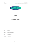
To start the demonstrator simply run the included script (.bat or .sh). This will bring up the Launcher window,
in which various options can be selected before running the demonstration proper. The figure below shows
the Launcher window.
Figure 2-1 TBS Launcher Window
2.2.1 Scenario
The first drop down menu allows the scenario to be chosen – simply select the name of the required scenario
from the list. Currently the scenarios define the traffic and the TBS area, though this can be extended to
cover more options.
2.2.2 Display size
The final drop down menu gives a range of options of display size, from which the most suitable option can
be selected to tailor the size of the CWP according to the screen on which it will be displayed.
GL/EDEP/C0095/UG/1
page 6 of 23
issue date: 06 February 2009
version: 1.0
Time-Based Separation Demonstrator
User Guide
2.2.3 Running
To run the demonstrator with the selected options, click on the “Run Test” button. It will be ready in a few
seconds, and two main windows will be displayed – the CWP itself (see the CWP guide [Ref 3]) and an eDEP
Console, for controlling the demonstration (see next section).
Alternatively, “View Traffic” can be clicked to run the PVT (see Ref 4) for viewing/editing traffic and airspace.
In particular it may be useful for determining the co-ordinates of the required TBS area (see TBS Area
Definition).
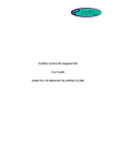
2.2.4 Demonstrator Management
An eDEP console window is displayed as part of the demonstrator, and is shown in the picture below:
Figure 2-2 eDEP Console Window
The four buttons, from left to right are:
Stop
- shuts down the demonstrator.
Pause
- pauses the demonstrator, while still allowing full interaction.
Play
- advances the time in the demonstrator in real-time.
Fast-forward
- doubles the current speed (plays at double-speed if paused).
The ‘TOOLS’ menu, has options to view the version of the eDEP platform the demonstrator is using, and to
view all the current resources (see 4.2).
2.3 Problem Reporting
Any problems found should, initially, be reported to the eDEP Project Manager.
Include a description of the problem, and a copy of the log-file “edep_log.txt”, that is created in the directory
from which the demonstrator is launched. It is useful, if possible, to activate debug output (see 4.2.3.1) before
running, to provide additional information in the log-file to help with investigating the problem.
GL/EDEP/C0095/UG/1
page 7 of 23
issue date: 06 February 2009
version: 1.0
Time-Based Separation Demonstrator
User Guide
3 During the Demo
This section covers the information needed during a demonstration, in particular the TBS windows and
features, but also ‘standard’ features that have been modified for the TBS demonstrator.
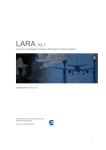
3.1 General
When the demo is launched, the CWP will appear, with layout and appearance similar to this screenshot:
Figure 3-1 CWP
The standard features, including toolboxes and menus are described in the CWP User Guide [Ref 3].
The TBS Configuration Window (top-right corner), TBS List Window (just below it), and Meteo Window are
described in the subsequent sections. The shaded area of the display denotes the area of airspace controlled
by this position, and the other outlined area marks the TBS area for the contained runway.
GL/EDEP/C0095/UG/1
page 8 of 23
issue date: 06 February 2009
version: 1.0
Time-Based Separation Demonstrator
User Guide
3.2 TBS Features
3.2.1 Configuration Window
Figure 3-2 TBS Configuration Window and Icon
The TBS Configuration Window is shown above in normal and iconized forms. Both forms show the version
of the current implementation of TBS. Clicking on the ‘dot button’ in the title bar of the window reduces it to an
icon; clicking on the icon restores it to the full window.
The window contains the following buttons and button groups:
TTP vector button
This simple on/off button controls the display of TTP vectors for
sequenced aircraft. More details on TTP vectors is given in section
3.2.3.
TBS and DBS mode buttons
These radio buttons (meaning only one can be selected at once)
control whether Time-Based or Distance-Based Separation
information is displayed.
TBS algorithm buttons
These radio buttons control which algorithm is used as the source of
information when the display is in TBS mode. Clicking on one when
in DBS mode also automatically changes the mode to TBS.
3.2.2 List Window
Figure 3-3 TBS List Window (empty) and Icon
The TBS List Window is shown above in its initial and iconized forms. Both forms show the name of the
runway for which the window displays sequence information. Clicking on the ‘dot button’ in the title bar of the
window reduces it to an icon; clicking on the icon restores it to the full window.
As aircraft enter the TBS area, and therefore the sequence, a line for each aircraft is added to the window, as
follows:
Figure 3-4 TBS List Window
GL/EDEP/C0095/UG/1
page 9 of 23
issue date: 06 February 2009
version: 1.0
Time-Based Separation Demonstrator
User Guide
Each line contains:
−
The position of the aircraft in the sequence,
−
the aircraft callsign,
−
the aircraft type,
−
the wake turbulence category of the aircraft,
−
the calculated length (in NM) of the aircraft’s TTP (Trailing Target Position) vector.
For certain categories, the wake turbulence section may be high-lighted (e.g. heavy) or low-lighted (e.g. light).
The high-lighting colour is the same as the TTP Vector display colour, which is dependent on the current
(TBS/DBS) display mode.
3.2.2.1 Aircraft Selection
An aircraft can be selected in the CWP by moving the mouse into its aircraft label or into its entry in a TBS
List Window. Selecting an aircraft causes it to be highlighted wherever it appears, i.e. selecting it in the TBS
List Window highlights the entry there and the aircraft label, and vice versa, as seen in this picture:
Figure 3-5 List Window and Aircraft Label Highlighting
Moving the mouse over the aircraft’s wake turbulence category, again in either location, also selects the
aircraft’s leader, highlighting that aircraft’s label and list window entry as well.
3.2.2.2 Sequence Modification
The default sequence can be modified. Clicking on a sequence number causes that aircraft, to be selected
for re-positioning: the sequence number is marked with a border, the cursor changes, and a horizontal line is
displayed indicating the insertion point. A modification in progress can be seen here:
Figure 3-6 List Window Sequence Modification
GL/EDEP/C0095/UG/1
page 10 of 23
issue date: 06 February 2009
version: 1.0
Time-Based Separation Demonstrator
User Guide
As the mouse is moved up and down, the line moves, jumping to the nearest insertion point, including before
the first aircraft, and after the last. If the mouse is clicked again, a request is sent to re-position the selected
aircraft at the indicated position in the sequence, and the sequence is re-calculated accordingly.
The operation can be cancelled by clicking the right mouse button anywhere.
Re-sequencing an aircraft causes a locking of the affected section of the sequence: from the first aircraft, up
to and including the aircraft concerned. Other aircraft will no longer be automatically inserted into a locked
section – the earliest they can be inserted is directly after the manipulated aircraft. Multiple re-sequences
nd
have a cumulative locking effect: a 2 aircraft re-positioned earlier in the sequence than the first will not
change the locked section, whereas one re-positioned later will extend the locked section to its own position.
Aircraft which are automatically inserted into a sequence, and are therefore affected by this locking, include
those entering the TBS area, and those whose trajectory is modified changing their planned arrival time, e.g.
a change of route or speed.
3.2.3 TTP Vector
The Trailing Target Position vector is displayed behind an aircraft and shows the position of minimum
separation for the follower aircraft:
Figure 3-7 Sequenced Aircraft with TTP Vectors
The calculated TBS vector for an aircraft pair is never longer than the equivalent DBS vector. A TBS vector,
even if calculated to be shorter, is never displayed shorter than the overall minimum DBS separation, typically
2.5 NM.
The colour of the vector depends on the separation being displayed – TBS or DBS. The previous screenshot
shows TBS mode, the next one, DBS mode.
Figure 3-8 TTP Vector in DBS mode
If a TBS vector increases in length by more than a defined tolerance, then after a short delay the TTP is
declared invalid, and will flash until it becomes valid again. The flash state can be seen in the picture below.
Note that this will only be seen in TBS mode.
Figure 3-9 Invalid TBS TTP Vector
GL/EDEP/C0095/UG/1
page 11 of 23
issue date: 06 February 2009
version: 1.0
Time-Based Separation Demonstrator
User Guide
3.2.4 TBS Area
The display of the TBS areas can be turned on and off via the Layers->OVERLAY MANAGER menu:
Figure 3-10 TBS Area Display Menu
3.2.5 Meteo Window
The Meteo Window displays, text form, the wind data for each defined weather layer. Each line shows the
altitude range over which it applies, the direction from which the wind is coming, and its strength in knots. A
simple example is shown here:
Figure 3-11 Meteo Window
The weather may change with time. The Meteo Window will quietly update the displayed data, but will not
draw attention to the changes.
GL/EDEP/C0095/UG/1
page 12 of 23
issue date: 06 February 2009
version: 1.0
Time-Based Separation Demonstrator
User Guide
3.3 Controlling Aircraft
Various controller orders can be given to the aircraft, via menus accessed from the aircraft label. These are
all described in the following sections.
3.3.1 Aircraft Label
A general description of aircraft labels, how they function, and their interactions is included in the CWP User
Guide [Ref 3] and makes useful background reading. This section describes the label as it appears in the
TBS demonstrator, and the following sub-sections describe the relevant interactions, and menus through
which controller orders can be given.
3.3.1.1 Appearance
The following are labels for aircraft not included in a TBS sequence:
Figure 3-12 Aircraft Labels (unselected and selected) for Un-sequenced Aircraft
The first (unselected) label shows the following information:
First row
o
Aircraft callsign
Second row
o
Current FL, with optional arrow indicating climbing or descending
o
Cleared FL (altitudes below the defined transition level are displayed with a leading zero)
o
Aircraft Speed, in 10s of knots
o
Aircraft Type
A selected label includes the following additional information:
Third row
o
Exit Waypoint (usually “BDY” – as the aircraft is landing, there is no next sector to exit to)
Fourth row
o
Assigned heading (or “ahdg” if no current controller order given)
o
Assigned Speed, in 10s of knots (or “asp” if no current controller order given)
o
Assigned Rate of Climb/Descent (or “arc” if no current controller order given)
The following are labels for aircraft included in a TBS sequence:
Figure 3-13 Aircraft Labels (unselected and selected) for Sequenced Aircraft
In addition to the standard information, the wake turbulence category of the aircraft, and that of the follower
aircraft, are displayed on the first row. The former follows the same colouring rules as in the TBS List Window
(3.2.2), the latter is the same colour as the TTP Vector (3.2.3).
GL/EDEP/C0095/UG/1
page 13 of 23
issue date: 06 February 2009
version: 1.0
Time-Based Separation Demonstrator
User Guide
3.3.1.2 Interactions
Clicking with the right-mouse button on the Callsign turns on or off the display of the trajectory and Extended
Label Window (ELW) for that aircraft:
Figure 3-14 Trajectory and Extended Label Window
The trajectory shows the remaining route, with waypoints, and time and altitude at each point. The ELW
shows the same as the aircraft label, with additional information including estimated arrival time, SSR code,
and origin and destination airports.
Pressing and holding (rather than clicking) the right-mouse button on the callsign displays the same
information, but only while the button is held.
These functions also operate from the callsign in the TBS List Window.
The same operations on the Exit Waypoint display the trajectory but not the ELW.
3.3.1.3 Kill Flight
It is possible to remove a flight from a simulation in progress. To do this double-click with the middle mouse
button on the aircraft’s callsign (again this will work in either the aircraft label or the TBS List Window). This
will activate the Kill Flight Dialog:
Figure 3-15 Kill Flight Dialog Box
Click on ‘Yes’ to confirm the kill operation. After a short delay the flight will disappear from the CWP, and in
the next update it will be removed from the TBS sequence, the sequence re-calculated, and the TBS List
Window contents updated accordingly.
GL/EDEP/C0095/UG/1
page 14 of 23
issue date: 06 February 2009
version: 1.0
Time-Based Separation Demonstrator
User Guide
3.3.2 Menus
3.3.2.1 Altitude Menu
The altitude menu is activated by clicking on the Cleared FL in the aircraft label:
The menu contains a range of flight-levels, centred on the aircraft’s current CFL.
The flight-levels available can be scrolled up or down using the arrow buttons.
As in the aircraft label, flight-levels below the defined transition level are displayed with a
leading zero.
Clicking on one of the values sends a CFL order to the aircraft: the new chosen value
will be displayed in the aircraft label, and the aircraft will climb/descend to the new level.
Clicking the right mouse button anywhere removes the menu without sending an order.
If no further altitude orders are given, the aircraft will continue to follow those in its
trajectory, typically a stepped descent to the runway threshold.
Figure 3-16 Altitude Menu
3.3.2.2 Direct To Menu
The direct-to menu is activated by clicking on the Exit Waypoint in the aircraft label:
The menu contains the next 7 waypoints on the aircraft’s trajectory.
Clicking on one of the waypoint names sends a direct order to the aircraft to head to
that waypoint: the clearance (waypoint name) will be displayed in the aircraft label, and
the aircraft will turn towards the point. The TBS sequence will be re-evaluated based on
the new trajectory, and the sequence modified and re-calculated if necessary and
possible (see 3.2.2.2 - Sequence Modification).
Clicking the right mouse button anywhere removes the menu without sending an order.
Figure 3-17 Direct To Menu
If no further lateral orders are given, once the aircraft reaches the selected waypoint it will follow the rest of its
trajectory.
GL/EDEP/C0095/UG/1
page 15 of 23
issue date: 06 February 2009
version: 1.0
Time-Based Separation Demonstrator
User Guide
3.3.2.3 Heading Menu
The heading menu is activated by clicking on the assigned heading (or “ahdg”) in the
aircraft label:
The menu contains a range of headings, centred on the aircraft’s current heading (or
nearest rounded value to it).
The headings available can be scrolled clockwise or anti-clockwise using the arrow
buttons.
Clicking on one of the values sends a heading order to the aircraft: the cleared value will
be displayed in the aircraft label, the aircraft will turn towards the point, and the
trajectory will be updated with a ‘best guess’ as to the controller’s intentions to guide the
aircraft to the runway. The TBS sequence will be re-evaluated based on this trajectory,
and the sequence modified and re-calculated if necessary and possible (see 3.2.2.2 Sequence Modification).
Clicking the right mouse button anywhere removes the menu without sending an order.
Figure 3-18 Heading Menu
There are two approaches to creating the ‘best guess’ trajectory above. If the chosen heading intercepts the
existing trajectory (after allowing for the aircraft to turn and follow the heading for a minimum amount of time),
then the initial heading, and the trajectory from the intersection point onwards, are used to compose the new
trajectory. If no intercept is found, then the existing trajectory is searched for a waypoint where only a gentle
turn is needed to re-join the trajectory, and the trajectory from this point onwards is used as the basis for the
new one instead.
Note, the aircraft will not follow the new trajectory: if no further lateral orders are given, it will continue on the
cleared heading indefinitely.
3.3.2.4 Speed Menu
The speed menu is activated by clicking on the assigned speed (or “asp”) in the aircraft
label:
The menu contains a range of speeds (in knots), centred on the aircraft’s current speed
(or nearest rounded value to it).
The speeds available can be scrolled up or down using the arrow buttons.
Clicking on one of the values sends a speed order to the aircraft: the new cleared value
will be displayed in the aircraft label, the aircraft will fly at the new speed, and the
trajectory is updated to reflect the new speed. The TBS sequence will be re-evaluated
based on the new trajectory, and the sequence modified and re-calculated if necessary
and possible (see 3.2.2.2 - Sequence Modification).
Clicking on RESUME sends an order to the aircraft to resume its default speed profile:
any previous speed clearance is removed from the aircraft label, and the same updates
are made as above.
Clicking the right mouse button anywhere removes the menu without sending an order.
Figure 3-19 Speed Menu
GL/EDEP/C0095/UG/1
page 16 of 23
issue date: 06 February 2009
version: 1.0
Time-Based Separation Demonstrator
User Guide
3.3.2.5 ROCD Menu
The rate of climb/descent menu is activated by clicking on the assigned rocd (or “arc”)
in the aircraft label:
The menu contains a range of vertical speeds.
The speeds available can be scrolled up or down using the arrow buttons.
Clicking on one of the values sends a vertical speed order to the aircraft: the new
cleared value will be displayed in the aircraft label, and the aircraft will climb/descend at
the requested rate for any current and future climbs/descents.
Clicking on RESUME sends an order to the aircraft to resume its default vertical speed
profile: any previous speed clearance is removed from the aircraft label, and the aircraft
uses its default climb/descent speeds from now on.
Clicking the right mouse button anywhere removes the menu without sending an order.
Figure 3-20 Rate of Climb/Descent Menu
GL/EDEP/C0095/UG/1
page 17 of 23
issue date: 06 February 2009
version: 1.0
Time-Based Separation Demonstrator
User Guide
4 Configuration
4.1 General
Several files that affect the operation of the TBS demonstrator are made available for editing so the
demonstrator can be customised. These are found under the tbs/resources directory. There are two types of
file:
1. GSDK resource file (.gsdk extension) containing resources in the format <Group>.<Name>
<Value>.
2. Data file (.dat extenstion) containing data in a structured format dictated by the reading component.
All files are in plain text (ASCII) and easily viewed and edited with any basic text editor.
4.2 Resource files
There are many resources in the system most of which are not relevant and/or should not be changed for the
TBS Demonstrator. The relevant, modifiable, resources have been grouped into a small number of GSDK
resource files, which can be found under the tbs/resources directory and are described in the sub-sections
below:
common/threshold_speeds.gsdk
defaults/cwp_defaults.gsdk
defaults/tbs_defaults.gsdk
The complete set of resources defined in the system can be viewed at any time, by selecting, from the
Console window, the TOOLS->Resources item. This brings up a window in which all the resources can be
browsed, but not edited – most of the ones relevant to the demonstrator start with “TBS.”!
4.2.1 Threshold Speeds
This file defines the threshold speed used for each aircraft type by the TCS implementation of the TBS
algorithm. The speeds are defined in the format:
TBS.THRESHOLD_SPEEDS (
(A306 130),
(A30B 135),
…
(TRIN 75)
)
where each line lists an aircraft type and the associated speed in knots.
If traffic is added with a new aircraft type not yet listed here, then a line should be added for it. Existing values
can also be modified, e.g. to improve accuracy.
4.2.2 CWP Defaults
This file contains resources controlling the display and operation of the CWP. Generally, it should not need to
be modified by the user. There are, however, a few entries that might be useful:
CWP_CDG.PVD.LATITUDE
CWP_CDG.PVD.LONGITUDE
CWP_CDG.PVD.SCALE
QNH.TRANSITION_LEVEL
49.1
3.0
300
65
The first three control the centre and zoom factor of the CWP when it is first displayed. The second, selfevidently, defines the transition level.
GL/EDEP/C0095/UG/1
page 18 of 23
issue date: 06 February 2009
version: 1.0
Time-Based Separation Demonstrator
User Guide
4.2.3 TBS Defaults
This file contains resources controlling the TBS implementation and calculations, though some will also affect
the CWP.
The following resource lists the runways for which a TBS sequence will be calculated and managed, along
with the associated TBS Area (for historical reasons the name of the TBS area is repeated). A TBS List
Window is created for each runway listed (see 3.2.2):
TBS.MANAGED_RUNWAYS
( (LFYP_27, CDG_COMP, CDG_COMP),
(LFZP_27, LFZP, LFZP) )
The algorithms resource lists the variants of the TBS algorithm along with the name of the implementing
class. An algorithm button is created in the TBS Configuration Window for each algorithm listed (see 3.2.1).
The subsequent entry defines which algorithm (button) is selected when the demonstrator is launched.
TBS.ALGORITHMS (
("TAS", "tbs.tbs.server.calculator.TASTBSTTPCalculatorImpl" ),
("HW", "tbs.tbs.server.calculator.HWTBSTTPCalculatorImpl" ),
("TCS", "tbs.tbs.server.calculator.TCSTBSTTPCalculatorImpl" ) )
TBS.INITIAL_ALGORITHM
"TAS"
The following resources list the meteo ‘tag’ to be used by each of the TBS implementation algorithms that
use meteo data. The names listed must correspond to a weather entity defined in the meteo data file (see
4.3.3):
TBS.METEO_TAG.TAS
TBS.METEO_TAG.HW
"ACTUAL"
"ACTUAL"
The following resource lists the defined wake turbulence categories, and their representative character. This
resource is in place for future enhancements and should not currently be modified:
TBS.WAKE_TURBULENCE_CATEGORIES
( ("H", "HEAVY" ),
("M", "MEDIUM" ),
("L", "LIGHT" ) )
The following resource defines the separation distances for the DBS algorithm for each possible LeaderFollower aircraft pair combination, based on the defined wake turbulence categories (Heavy, Medium, Light).
It is laid out with leader aircraft in rows and follower aircraft in columns, so for example, the first entry on the
last row (highlighted) gives the separation for a heavy aircraft following a light leader aircraft:
TBS.DBS_SEPARATION_DISTANCES
( ( 4,
5,
6),
(2.5, 2.5,
5),
(2.5, 2.5, 2.5) )
The following resource controls whether or not a list window that has been iconified should be automatically
restored when its contents change (aircraft added or removed, or sequence changed):
TBS.LIST_WINDOW.AUTO_RESTORE
TRUE
4.2.3.1 Debug output
Additional debug information detailing the calculations and operation of the TBS server can be included in the
log file by uncommenting the following two lines (removing the leading ‘//’):
//DEBUG
//TBS.DEBUG_APP
TRUE
TRUE
This information is quite verbose, and in a busy scenario (or at higher speeds) can significantly affect
performance, so this should only be activated if needed.
GL/EDEP/C0095/UG/1
page 19 of 23
issue date: 06 February 2009
version: 1.0
Time-Based Separation Demonstrator
User Guide
4.3 Data files
The following data files are available and are described in the sub-sections below:
common/airspace.dat
common/bada_performance.dat
meteo file (in defaults)
TBS areas files (in defaults)
traffic files (in scenarios)
4.3.1 Airspace Data
This file defines the airspace features used by the demonstrator: fixes, airports, sectors, runways, etc. It
should not normally need modifying, but extra fixes or STARs could be added, for example. The format is
usually self-explanatory from the existing entries.
4.3.2 BADA Data
This file contains BADA aircraft performance data, previously converted to the eDEP file format. It defines
various parameters for each aircraft type. The section of interest for the TBS demonstrator is the low level
speed profile (the descent CAS in particular) defined for each aircraft type:
LOW_LEVEL_SPEED
ALTITUDE
CLIMB_CAS
ALTITUDE
DESCENT_CAS
END
0 3000 6000 10000
155 180 250 250
10000 6000 3000 0
250 220 220 130
An arbitrary number of altitudes and corresponding CAS values can be defined. A descending aircraft
gradually decelerates from its general descent CAS, to the descent CAS defined for the highest altitude in
this low level speed section, starting at 1.2 times this altitude. E.g. for the speeds defined above, at 10,000ft,
6,000ft, etc., the aircraft will start to decelerate when it reaches 12,000ft, reaching a CAS of 250 knots at
10,000ft. Below this level there is a similar linear deceleration from one speed/altitude to the next.
If traffic is added with a new aircraft type not yet listed here, then a complete entry should be added for it.
4.3.3 Meteo Data
This file contains meteo data, specifically one or more named weather definitions, forming a grid centred on a
point, with 1 or more timed sets of weather data defined in layers:
WEATHER ACTUAL
GRID
2 2
48.9 2.4
// degrees
TIME
"17:45:00"
LAYER ALTITUDE 0
WINDSPEED
WINDDIRECTION
END
LAYER ALTITUDE 2001
WINDSPEED
WINDDIRECTION
END
LAYER ALTITUDE 5001
WINDSPEED
WINDDIRECTION
END
LAYER ALTITUDE 8001
WINDSPEED
WINDDIRECTION
END
2000
ROW
ROW
15
300
5000
ROW
ROW
25
270
8000
ROW
ROW
30
330
12000
ROW
25
ROW
310
GL/EDEP/C0095/UG/1
page 20 of 23
issue date: 06 February 2009
version: 1.0
Time-Based Separation Demonstrator
User Guide
TIME
LAYER …
"18:15:00"
In the example above, one weather entity, named “ACTUAL” is defined over point 48.9°, 2.4° with a grid
spacing of 2° latitude and 2° longitude, and a 1x1 g rid of data defined in each layer. An arbitrary number of
timed weather sets, layers, and grid sizes can be used, though the grid size must be the same in each case.
The layers need not be the same in number or altitude range at each time.
An entry for “ACTUAL” must be included for the TBS demonstrator, though additional entries can be added,
e.g. for use by the TBS algorithms (see 4.2.3 - TBS Defaults above).
The following shows a sample extract for a weather entity with a 2x3 grid:
WEATHER ACTUAL
GRID
2.0
48.0 2.5
1.5
// degrees
TIME
"18:00:00"
LAYER ALTITUDE 0
WINDSPEED
WINDDIRECTION
END
LAYER ALTITUDE
WINDSPEED
3001
WINDDIRECTION
3000
ROW
ROW
ROW
ROW
15
13
300
310
17
16
300
290
16
16
285
290
7000
ROW
ROW
ROW
ROW
20
22
300
320
21
21
300
295
18
19
285
303
END
Although a grid of any size can be defined, and will be taken into account by the demonstrator, both for
calculating trajectories, and TBS vectors, only the first element from any layer will currently be displayed in
the Meteo Window (3.2.5).
4.3.4 TBS Area Definition
Three TBS area definition files are provided, with entries like the following
TBSAREA CDG_COMP
REGION
ALTITUDE 0.0 99000.0
49.0
2.25
49.0
2.84
49.15
2.84
49.15
3.75
48.71
3.75
48.71
2.84
48.85
2.84
48.85
2.25
END
COMPUTE RUNWAY LFYP_27
The first line defines the area name. The area will be used for the calculation of a sequence for the runway
defined in the last line. The area is a region whose outline is defined by an arbitrary number of lat/long points,
and extending over an altitude range defined in feet.
4.3.5 Traffic Files
Three traffic files are provided, which can be modified/duplicated to change aircraft callsigns, start times,
aircraft type and/or wake turbulence, starting level, route/STAR, etc.
GL/EDEP/C0095/UG/1
page 21 of 23
issue date: 06 February 2009
version: 1.0
Time-Based Separation Demonstrator
User Guide
4.4 Adding A New Scenario
One default scenario and two variations are supplied:
scenarios/default_scenario.gsdk
scenarios/scenario2.gsdk
scenarios/scenario3.gsdk
It is not recommended that the default scenario is changed. New scenarios can be added, modelled on the
other two files, whose contents are similar to the following:
@LOAD "tbs/resources/scenarios/base_scenario.gsdk"
ASP.SCENARIO
( "tbs/resources/common/airspace.dat",
"tbs/resources/defaults/tbs_areas_medium.dat" )
IFPL.SCENARIO
"tbs/resources/scenarios/traffic3.dat"
METEO.SCENARIO
"tbs/resources/defaults/default_meteo.dat"
Ignoring the top line, the remaining entries allow the airspace and TBS areas, the traffic, and the meteo files
to be changed. From these, a large variety of scenarios can be constructed. Only the items being modified
need to be included, though if the airspace item is present it must list both the standard airspace and the TBS
areas file to be used.
The time at which a scenario starts can also be altered by adding an entry like the following:
CLOCK.STARTTIME
"15:00:00"
In order to run a new scenario, an entry must be added to the file scenarios.dat.
E.g. tbs/resources/scenarios/new_scenario.gsdk
This will then appear in the list of scenarios in the Launcher Window (see 2.2) and can be selected before
starting the demonstrator.
GL/EDEP/C0095/UG/1
page 22 of 23
issue date: 06 February 2009
version: 1.0
Time-Based Separation Demonstrator
User Guide
5 Glossary
AFL
Actual Flight Level
ATM
Air Traffic Management
BADA
Base of Aircraft Data
CAS
Calibrated Air Speed
CFL
Cleared Flight Level
CWP
Controller Working Position
DBS
Distance Based Separation
DDD
Detailed Design Document
eDEP
Early Development and Evaluation Platform
ELW
Extended Label Window
FL
Flight Level
GSDK
Graffica System Development Kit
HMI
Human-Machine Interface
HW
Head Wind
JRE
Java Runtime Environment
PVT
Profile Validation Tool
ROCD
Rate of Climb/Descent
SRD
Software Requirements Document
SSR
Secondary Surveillance Radar
STAR
Standard Terminal Arrival Route
TAS
True Air Speed
TBS
Time Based Separation
TCS
Threshold Crossing Speed
TTP
Trailing Target Position
WTC
Wake Turbulence Category
GL/EDEP/C0095/UG/1
page 23 of 23
issue date: 06 February 2009
version: 1.0