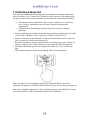
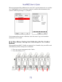
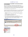
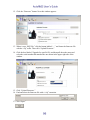
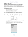
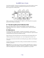
1
Product Registration Register your product online by visiting: www.raesystems.com/support/product-registration By registering your product, you can: Receive notification of product upgrades or enhancements Be alerted to Training classes in your area Take advantage of RAE Systems special offers and promotions Contents Read Before Operating ............................................................................................................. 4 1. AutoRAE 2 Automatic Test and Calibration System - General Information .............................. 5 2. Specifications .............................................................................................................................. 7 3. Overview ..................................................................................................................................... 9 3.1. Standard Package Contents...................................................................................... 13 4. Installing End Caps For Stand-Alone Use................................................................................. 14 5. Powering The AutoRAE 2 Cradle ............................................................................................. 15 6. Preparing For Bump Testing & Calibration .............................................................................. 16 6.1. Installing An External Filter .................................................................................... 16 6.2. Connecting An AC Adapter..................................................................................... 16 6.3. Connecting Calibration Gas ..................................................................................... 17 6.4. Placing A MultiRAE Monitor In The Cradle .......................................................... 19 6.5. Placing A ToxiRAE Pro Monitor In The Cradle ..................................................... 20 6.5.1. Installing Adapters In The ToxiRAE Pro Cradle ........................................................ 20 6.5.2. Placing A ToxiRAE Pro Monitor In The Cradle ........................................................ 21 6.6. Placing A QRAE 3 Monitor In The Cradle ............................................................. 22 6.7. Warm-Up ................................................................................................................. 22 7. Performing A Bump Test .......................................................................................................... 24 8. Performing A Calibration .......................................................................................................... 25 9. Bump And Cal Error And Status Messages .............................................................................. 26 10. Charging An Instrument’s Battery .......................................................................................... 28 11. Removing An Instrument From A Cradle ............................................................................... 28 11.1. AutoRAE 2 Reports ................................................................................................. 29 12. Printing Reports From An AutoRAE 2 Cradle........................................................................ 31 13. Programming A Stand-Alone AutoRAE 2 Cradle .................................................................. 32 13.1. Gas Inlet Configuration Settings ............................................................................. 35 13.2. Selectable Gas Index Values For Gas Config 8 ....................................................... 38 13.3. Gas Name ................................................................................................................ 39 13.4. Concentration [Value] ............................................................................................. 39 13.5. Concentration Unit................................................................................................... 39 13.6. Purge Time (Sec.) .................................................................................................... 39 13.7. Soak Time (Sec.) ..................................................................................................... 39 13.8. Uploading Settings To The AutoRAE 2 Cradle ...................................................... 40 13.9. Downloading & Uploading Individual Gas Inlet Settings ....................................... 40 13.10. Saving The Settings File .......................................................................................... 41 13.11. Recalling Stored Settings ......................................................................................... 41 13.12. Uploading Settings To Multiple AutoRAE 2 Cradles ............................................. 41 13.13. Exiting Programming............................................................................................... 41 14. Upgrading Firmware On The AutoRAE 2 Cradle ................................................................... 42 15. Using A Stand-Alone AutoRAE 2 Cradle For Datalog Transfer, Monitor Configuration, and Firmware Upgrades .......................................................................................................... 45 16. Overview ................................................................................................................................. 46 16.1. Standard Package Contents...................................................................................... 47 17. Operation of an AutoRAE 2 Controller-based System ........................................................... 48 18. Setting Up an AutoRAE 2 Controller-based System............................................................... 48 18.1. Installing Batteries For The Real-Time Clock......................................................... 49 18.2. Attaching An External Filter ................................................................................... 50 19. Powering an AutoRAE 2 Controller-Based System ................................................................ 50 20. Operating A Controller And Attached Cradles ....................................................................... 51 20.1. Turning The AutoRAE 2 Controller On .................................................................. 51 20.2. Turning The AutoRAE 2 Controller Off ................................................................. 51 20.3. Startup Routine ........................................................................................................ 51 20.4. User Interface .......................................................................................................... 53 20.5. Display Status Messages and Color Coding ............................................................ 54 20.6. Warm-Up ................................................................................................................. 54 20.7. Testing ..................................................................................................................... 55 20.7.1. Compatibility Testing ............................................................................................... 55 21. Preparing For Bump Testing & Calibration ............................................................................ 57 21.1. SD Memory Card..................................................................................................... 57 21.1.1. Installing An SD Card............................................................................................... 59 21.1.2. Removing An SD Card ............................................................................................. 59 21.2. Connecting Calibration Gas ..................................................................................... 60 21.3. Placing Monitors In Cradles .................................................................................... 61 21.4. Performing A Bump Test......................................................................................... 61 21.4.1. Interrupting A Bump Test ......................................................................................... 65 21.5. Performing Calibration ............................................................................................ 68 21.5.1. Interrupting A Calibration ........................................................................................ 70 21.6. Direct Bump Testing And Calibrating Via The Cradles’ Buttons ........................... 72 21.7. Printing and Configuration Settings ........................................................................ 74 21.7.1. Printing ..................................................................................................................... 74 21.8. Settings .................................................................................................................... 77 21.8.1. Gas Settings .............................................................................................................. 80 21.8.2. System Settings ......................................................................................................... 81 21.8.3. Network Settings ...................................................................................................... 82 22. Programming An AutoRAE 2 Controller-based System on the Computer ............................. 84 22.1. Gas Inlet Settings ..................................................................................................... 89 22.2. Configuring A Gas Inlet .......................................................................................... 89 22.2.1. Gas Number .............................................................................................................. 90 22.2.2. Gas Lot Number ....................................................................................................... 90 22.2.3. Expiration Date ......................................................................................................... 90 22.2.4. Gas Index .................................................................................................................. 90 22.2.5. Gas Name.................................................................................................................. 90 22.2.6. Concentration [Value]............................................................................................... 90 22.2.7. Concentration Unit.................................................................................................... 91 22.2.8. Purge Time (Sec.) ..................................................................................................... 91 22.2.9. Soak Time (Sec.) ...................................................................................................... 91 22.3. Uploading Settings To The AutoRAE 2 .................................................................. 92 22.4. Downloading & Uploading Individual Gas Bottle Settings .................................... 92 22.5. Saving The Settings File .......................................................................................... 93 22.6. Recalling Stored Settings ......................................................................................... 93 22.7. Uploading Settings To Multiple AutoRAE 2 Systems ............................................ 93 22.8. Exiting Programming............................................................................................... 93 23. Updating Firmware On The AutoRAE 2 Controller ............................................................... 94 24. Transferring AutoRAE 2 Controller Data To A Computer ..................................................... 98 24.1. Exporting Reports .................................................................................................. 103 24.2. Saving A Configuration Upon Exit ....................................................................... 104 25. Wireless Operation ................................................................................................................ 105 25.1. Part One: Configure The AutoRAE 2 Network Interface ...................................... 105 25.2. Part Two: Configure The WiFi Adapter & Test The Network .............................. 106 26. Wall Mounting A Controller & Cradles ................................................................................ 111 27. Transferring Bump And Calibration Data ............................................................................. 112 28. Maintenance .......................................................................................................................... 112 29. Technical Support.................................................................................................................. 113 30. RAE Systems Contacts .......................................................................................................... 113 WARNINGS Read Before Operating This manual must be carefully read by all individuals who have or will have the responsibility of using, maintaining, or servicing this product. The product will perform as designed only if it is used, maintained, and serviced in accordance with the manufacturer’s instructions. Proper Product Disposal At End Of Life The Waste Electrical and Electronic Equipment (WEEE) directive (2002/96/EC) is intended to promote recycling of electrical and electronic equipment and their components at end of life. This symbol (crossed-out wheeled bin) indicates separate collection of waste electrical and electronic equipment in the EU countries. This product may contain one or more Nickel-metal hydride (NiMH), Lithium-ion, or Alkaline batteries. Specific battery information is given in this user guide. Batteries must be recycled or disposed of properly. At the end of its life, this product must undergo separate collection and recycling from general or household waste. Please use the return and collection system available in your country for the disposal of this product. Sensor Specifications, Cross-Sensitivities, And Calibration Information The AutoRAE 2 can be used to calibrate a wide variety of sensors. For calibration information and specifications and cross-sensitivities of various sensors refer to RAE Systems Technical Note TN-114: Sensor Specifications And Cross-Sensitivities (available for free download from www.raesystems.com). All specifications presented in this Technical Note reflect the performance of standalone sensors. Actual sensor characteristics may differ when the sensor is installed in different instruments. As sensor performance may change over time, specifications provided are for brand-new sensors. Make Sure Firmware Is Up To Date For best operation, make sure your monitors, AutoRAE 2 Controller and AutoRAE 2 Cradles are running the latest firmware. 1. Controller firmware. 2. Cradle firmware. 3. Instrument firmware. 1. AutoRAE 2 Automatic Test and Calibration System General Information The AutoRAE 2 Automatic Test and Calibration System for new RAE Systems portable gas monitors makes compliance with monitor test and calibration requirements as easy as pressing a button. Simply cradle the monitor and the system will take care of all calibration, testing, and recharging. The AutoRAE 2 is a flexible, modular system that can be configured to meet your calibration requirements effectively and efficiently. An AutoRAE 2 system can be as simple as a single cradle deployed in standalone mode to calibrate one instrument at a time, or as powerful as a networked1, controller-based system supporting ten monitors and five distinct calibration gas cylinders. Key Features Automatic testing, calibration, charging, and reports management Deployable as a standalone cradle or a controller-based system with up to 10 cradles Controller with a large, color LCD display Up to 5 calibration gas cylinders can be connected at the same time* Data storage on a standard SD card2 Bench-top or wall-mounted use Instruments supported: MultiRAE Lite (Pumped), MultiRAE, and MultiRAE Pro, ToxiRAE Pro, ToxiRAE Pro PID, ToxiRAE Pro LEL, and ToxiRAE Pro CO2, and QRAE 3 (pumped and diffusion models) Unique cradle for all ToxiRAE Pro family (cradle supplied with adapters) Networking capability (optional) Wireless networking capability using external Wi-Fi module for AutoRAE 2 (optional) Benefits Easy, one-touch bump testing, calibration, charging, and reports management Supports a wide variety of gases, including exotics Optimized for field use—does not require a computer to operate Firmware-upgradeable to protect your investment ______________ * Supported only on AutoRAE 2 Controller-based systems Summary Of Differences Between An AutoRAE 2 Controller-Based System And A Stand-alone Cradle Controller-Based System Monitors calibrated simultaneously Up to 10 Number of gas inlets (distinct 5 dedicated gas inlets plus calibration gas cylinders) fresh air with dedicated exhaust port on the Controller Display 5.7" TFT (320 x 240) graphical backlit color LCD on the Controller + 2 seven-segment LED displays on each Cradle Buttons 3 buttons ([Mode], [Y/+], and [N/-]) on the Controller + 2 buttons ([Bump] and [Cal]) on each Cradle Power supply 12V, 7.5A output Charges up to 10 instruments at a time Printer support Printing Built-in pump Data storage Networking Built-in pump (500 ml/min) in the Controller Standard 2 GB SD card with security lock on the Controller RJ-45 10/100 Base-T port on the Controller Standalone Cradle 1 2 dedicated gas inlets plus fresh air with dedicated exhaust port 2 seven-segment LED displays 2 buttons ([Bump] and [Cal]) 12V, 1.25A output Charges one instrument at a time Direct printing on Serial (RS-232) printers Automatic MultiRAE Cradle relies on MultiRAE’s pump to pull in air. ToxiRAE Pro Cradle has 300cc/min internal pump None. Data stored only on the PC None 2. Specifications Size AutoRAE 2 Controller MultiRAE Cradle ToxiRAE Pro Cradle QRAE 3 Cradle Terminal Adapter 5.63" W x 10.43" L x 1.73" H (143 x 265 x 44 mm) 6.50" W x 12.68" L x 4.37" H (165 x 322 x 111 mm) 6.50" W x 11.61" L x 3.91" H (165 x 295 x 99 mm) 6.50" W x 12.60" L x 4.65" H (165 x 320 x 118 mm) 2.17" W x 8.86" L x 1.65" H (55 x 225 x 42 mm) Weight AutoRAE 2 Controller MultiRAE Cradle ToxiRAE Pro Cradle QRAE 3 Cradle Terminal Adapter 1.9 lbs. (0.86 kg) 1.9 lbs. (0.86 kg) 1.96 lbs. (0.89 kg) 2.16 lbs. (0.98 kg) 0.33 lbs. (0.15 kg) Power Supply AutoRAE 2 Controller: Cradle: AC adapter (110V to 240V input, 12V, 7.5A output) Charges up to 10 instruments at a time AC adapter (110V to 240V input, 12V, 1.25A output) Charges one instrument at a time Cradles Supported AutoRAE 2 Controller Cradle Up to 10 cradles total (any mix) No additional cradles supported Display AutoRAE 2 Controller Cradle 5.7" TFT (320 x 240) graphical backlit color LCD 2 seven-segment LEDs Buttons AutoRAE 2 Controller Cradle 3 buttons ([Mode], [Y/+], and [N/-]) 2 buttons ([Bump] and [Cal]) Real-time Clock AutoRAE 2 Controller Cradle Yes Yes Visible Alarm/ Indicators AutoRAE 2 Controller Cradle Color graphical LCD display Tri-color (red/green/yellow) LED lights Audible Alarm AutoRAE 2 Controller Cradle 90dB @ 12" (30 cm) Same as above Gas Inlet/Outlet Ports AutoRAE 2 Controller Cradle 6 inlets (1 dedicated fresh air inlet and 5 configurable calibration gas inlets); 1 exhaust port 3 inlets (1 dedicated fresh air inlet and 2 configurable calibration gas inlets); 1 exhaust port Gas Port Connectors AutoRAE 2 Controller Cradle: Connectors with 200-series barbs, 1/8" (3.18 mm) ID tubing Same as above Gas Regulator AutoRAE 2 Controller Cradle Demand-flow regulator (0 to 1,000 psig/70 bar) Same as above Pump Flow Rate AutoRAE 2 Controller MultiRAE Cradle ToxiRAE Pro Cradle QRAE 3 Cradle Built-in pump (500 ml/min) None; relies on instrument’s pump to pull in air 400cc/min pump (typical) 400cc/min pump (typical) Data Storage AutoRAE 2 Controller Cradle Standard 2 GB SD card with security lock None. Data stored only on PC PC Communications AutoRAE 2 Controller Cradle USB (Type B) port for direct connection to PC Same as above AUTORAE 2 CRADLE 3. Overview An AutoRAE 2 Cradle can be deployed as a stand-alone station for automatic charging, bump testing, and calibrating monitors and printing certificates on a serial printer, or as part of an AutoRAE 2 Controller-based system, which can accommodate up to 10 AutoRAE 2 Cradles. These can be all the same or a mix of MultiRAE, QRAE 3, and ToxiRAE Pro models. When an AutoRAE 2 Cradle is connected to the AutoRAE 2 Controller, all electrical, electronic, and gas connections are automatically internally connected. A controllerbased system can accommodate up to five distinct gas sources for multi-sensor calibration and bump testing. An AutoRAE 2 Cradle can be used on a tabletop (or other flat surface) or mounted on a wall. Wall-mounting instructions are included in this guide. MultiRAE Cradle Capture mechanism Filter Release mechanism Air inlet Sensors for testing MultiRAE LED alarms Exhaust port (not shown) End cap, right 2 gas inlets (not shown) Sensor for testing MultiRAE buzzer End cap, left USB port (not shown) Sensors for testing MultiRAE LED alarms DC input from AC adapter 2-character LED display Charge contacts Charging status LED Bump/Status LED ToxiRAE Pro Cradle Bump Cal key key Cal/Status LED Capture mechanism Filter (hidden) Release mechanism Air inlet (hidden) Sensors for testing ToxiRAE Pro LED alarms Exhaust port (not shown) End cap, right 2 gas inlets (not shown) Sensor for testing ToxiRAE Pro buzzer USB port (not shown) DC input from AC adapter 2-character LED display Charge contacts (hidden) Charging status LED Bump/Status LED Bump Cal key key Cal/Status LED QRAE 3 Cradle Capture mechanism Filter Release mechanism Air inlet Sensors for testing QRAE 3 LED alarms Exhaust port 2 gas inlets Sensors for testing QRAE 3 LED alarms Sensor for testing QRAE 3 buzzer USB port (not shown) Charge contacts DC input from AC adapter 2-character LED display Charging status LED Bump/Status Bump key LED Cal key Cal/Status LED End Cap With Ports, All Models Exhaust Gas port ports USB port 12V DC power Input The USB port has a sliding cover that protects the contacts from contamination when it is not in use. Simply slide the cover over the port. 3.1. Standard Package Contents The AutoRAE 2 Cradle for MultiRAE Pumped Monitors (P/N T02-0103-000), QRAE 3 Pumped Monitors (P/N T02-0203-000), and AutoRAE 2 Cradle for ToxiRAE Pro Monitors (P/N T02-0003-000) are shipped with the following: AutoRAE 2 Cradle for MultiRAE Pumped Monitors, AutoRAE 2 Cradle for QRAE 3 Pumped Monitors, or AutoRAE 2 Cradle for ToxiRAE Pro Monitors Left and right end caps (for deployment in stand-alone mode) For ToxiRAE Pro Cradle only: Cradle comes with ToxiRAE Pro Cradle adapters and stickers for different ToxiRAE Pro models 4 screws and 4 screw covers to attach the right end cap to the Cradle if deployed in stand-alone mode or Cradle to a controller-based system 12-volt, 1.25A power supply with interchangeable plugs, P/N 500-0114-000 External inlet filters: 1 installed, three spare (P/N 008-3022-003, pack of 3) Tygon tubing (1/8" I.D., 15mm long), pack of 5, P/N 411-0018-037-05 PC Communications Cable, USB Type A (Male) to Type B (Male), P/N 410-0086-000 Quick Start Guide, P/N T02-4014-000 AutoRAE 2 Resource CD-ROM, P/N T02-4012-000 This disc includes: User’s Guide QuickStart Guide ProRAE Studio II Instrument Configuration and Data Management Software CDROM, P/N 000-5007-001 Product registration card Quality inspection and test certificate 4. Installing End Caps For Stand-Alone Use The AutoRAE 2 Cradle is shipped with left and right end caps, which are intended to protect and label the ports on both sides of the AutoRAE 2 Cradle. The one for the ―input‖ side (left end cap) snaps on, while the one on the other side (right end cap) gets slipped into its position and is then secured with two screws (plastic caps are included, to hide the screws). Note that the same end caps fit both MultiRAE, QRAE 3, and ToxiRAE Pro models. Slide the cap over the end and snap it into place. Insert the two screws. Slide the second cap into place. Tighten the screws. Do not overtighten! Press the caps over the screws. 5. Powering The AutoRAE 2 Cradle When used as a stand-alone unit, the AutoRAE 2 Cradle is powered by its own AC adapter. (When an AutoRAE 2 Cradle is attached to an AutoRAE 2 Controller, it receives its power from the AutoRAE 2 Controller, and therefore does not need a separate AC adapter.) The jack for the AC adapter connection is in the recess of the left end cap. Plug the barrel end of the AC adapter into the AutoRAE 2 Cradle and the transformer into an AC outlet. Caution: Never use the AutoRAE 2 Cradle or its AC adapter in wet or damp environments or hazardous locations. Plug barrel from AC adapter into jack 6. Preparing For Bump Testing & Calibration Before performing a bump test or calibration, the AutoRAE 2 Cradle must be set up, filter installed, and power applied. In addition, it must be configured using ProRAE Studio II software to set the gas types and concentrations, as well as the time and date. See page 32 for details. 6.1. Installing An External Filter In order to ensure that fresh air is uncontaminated by dust or other materials, use a filter on the AutoRAE 2 Cradle’s fresh air inlet. The inlet is located on the top end, to the left of the locking mechanism. Inspect the filter periodically and replace it as necessary if dirty, damaged, or contaminated. Press filter onto receptacle 6.2. Connecting An AC Adapter The AutoRAE 2 Cradle uses a 12V, 1.25A DC adapter. Plug the barrel end into the port on the side of the AutoRAE 2 Cradle and the transformer end into an AC power source. There is no power switch, so when power is applied to the AC adapter, the AutoRAE 2 Cradle is powered. Caution: Never use the AutoRAE 2 Cradle or its AC adapter in wet or damp environments or hazardous locations. 6.3. Connecting Calibration Gas The AutoRAE 2 Cradle can accommodate two gas calibration gas cylinders (mixture or single gas in each). In addition, there is a connection labeled ―Exhaust,‖ for venting the gas after it has gone through the AutoRAE 2 Cradle. All three connections are barbed to secure the hoses to them. All gas connections are barbed to secure the hoses to them. Appropriately non-reactive/non-adsorptive tubing with a 1/8" I.D. should be used (Teflon for PID or corrosive or reactive gases, Tygon for others). The cylinders must have demand-flow regulators (0 to 1,000 psig/70 bar) installed. Exhaust Calibration gas cylinder 1 Calibration gas cylinder 2 IMPORTANT! Always check that the active gas configuration on the AutoRAE 2 Cradle and the type/concentration of the actual calibration gases connected to the Cradle match before you begin any bump test or calibration. Cross-Sensitivities Determine The Order In Which Sensors Should Be Calibrated Gases used for calibration should be configured and connected to inlet 1 and then inlet 2 in the order in which the sensors should be calibrated. This applies to both a standalone cradle and controller-based systems. Information on the order of calibration is available in RAE Systems Technical Note TN-114. If MultiRAE sensors have cross-sensitivities to the target gas(es) of other sensors installed in the same instrument, the order in which such sensors are calibrated is important, as time is required between calibrations to allow the sensors to clear after exposure to cross-sensitive gas. To shorten the time required to perform calibration, calibrate the most cross-sensitive sensor first, followed by the least cross-sensitive. Wait for both sensors to recover to zero, and then expose both to gas again with most cross sensitive first and least cross sensitive second. For example, 50 ppm of NH3 produces 0 ppm response on a Cl2 (less cross-sensitive) sensor and 1 ppm of Cl2 produces about -0.5 ppm of response on a NH3 (more crosssensitive) sensor. So calibrate the NH3 sensor first with 50 ppm of NH3. This should have no effect on the Cl2 sensor. Then calibrate the Cl2 sensor with 10 ppm Cl2. This will send the NH3 sensor negative for some period of time. After calibrating the Cl2 sensor, return the instrument to clean air and wait until the most cross-sensitive sensor (NH3) fully recovers and/or stabilizes (if it stabilizes to a number other than zero, then re-zero the instrument). After both sensors return to zero, expose both to calibration gas in the same order (NH3 first, and then Cl2.) Note the sensor response. If both sensors are within 10% of the value shown on the gas cylinder, then the calibration of the cross-sensitive sensors was successful. This same logic applies to the order of performing a bump test on an instrument that has cross-sensitive sensors. For more information on cross-sensitivities for select sensors, consult RAE Systems Technical Note TN-114. 6.4. Placing A MultiRAE Monitor In The Cradle 1. Make sure the external filter on the instrument is not dirty or clogged and screwed onto the instrument inlet tightly. 2. Make sure the monitor is either turned off or is in AutoRAE 2 Communications Mode. 3. Place the instrument into the cradle face-down, making sure that it is aligned correctly with the contacts on the AutoRAE 2 Cradle’s charging port. There are two alignment points on one side and one alignment point on the other side, designed to mate with matching points on the bottom of the MultiRAE. 4. Press in on the capture mechanism to lock the MultiRAE in place. Note: There is no need to remove the external filter, rubber boot, belt clip or wrist strap from the monitor to use it with the AutoRAE 2. 6.5. Placing A ToxiRAE Pro Monitor In The Cradle The ToxiRAE Pro cradle requires one of two different adapters, and each is specific to the type of ToxiRAE Pro. They click into place and can be easily removed, in case you want to use one cradle for bump testing/calibrating/managing different types of ToxiRAE Pro monitors. 6.5.1. Installing Adapters In The ToxiRAE Pro Cradle The two types of ToxiRAE Pro adapters are shown here: Adapter for ToxiRAE Pro, ToxiRAE Pro CO2 and ToxiRAE Pro LEL Adapter for ToxiRAE Pro PID Align the two holes in the appropriate adapter with the two matching ports inside the Capture Mechanism. Adapter for ToxiRAE Pro, ToxiRAE Pro CO2 and ToxiRAE Pro LEL Adapter for ToxiRAE Pro PID Note: The adapters can be removed by pulling on the ―thumb tab‖ at the top of each one (it fits into a niche in the capture mechanism). Each adapter comes with a sticker for the inside of the cradle. It is especially recommended that you install these stickers, particularly if both types of adapters are being used in multiple cradles connected to an AutoRAE 2 Controller. Place self-adhesive sticker here 6.5.2. Placing A ToxiRAE Pro Monitor In The Cradle 1. Make sure the correct adapter is located in the cradle’s capture mechanism. 2. Make sure the external filter on the instrument is not dirty or clogged and screwed onto the instrument inlet tightly. 3. Make sure the monitor is either turned off or is in AutoRAE 2 Communications Mode. 4. Place the instrument into the cradle face-down, making check that it is aligned correctly with the contacts on the AutoRAE 2 Cradle’s charging port. 5. Press in on the capture mechanism to lock the ToxiRAE Pro in place. Note: There is no need to remove the external filter, rubber boot, belt clip or wrist strap from the monitor to use it with the AutoRAE 2. 6.6. Placing A QRAE 3 Monitor In The Cradle 1. Make sure the external filter on the instrument is not dirty or clogged and screwed onto the instrument inlet tightly. 2. Make sure the monitor is either turned off or is in AutoRAE 2 Communications Mode. 3. Place the instrument into the cradle face-down, making sure that it is aligned correctly with the contacts on the AutoRAE 2 Cradle’s charging port. There are two alignment points on one side and one alignment point on the other side, designed to mate with matching points on the bottom of the QRAE 3. 4. Press in on the capture mechanism to lock the QRAE 3 in place. Note: There is no need to remove the external filter, belt clip or wrist strap from the monitor to use it with the AutoRAE 2. 6.7. Warm-Up When you place a monitor in the cradle and lock the capture mechanism, the Cradle automatically starts charging the instrument and initiates a warm-up cycle to prepare the instrument for bump testing or calibration. In order for the warm-up cycle to commence, however, the monitor needs to be either turned off or in AutoRAE 2 Communications mode. The warm-up time depends on the sensors installed in the instrument and their individual warm-up requirements. During warm-up, the two Cradle LEDs labeled ―Bump‖ and ―Cal‖ blink orange in alternation. When the instrument is warmed up, the two LEDs glow continuously green, indicating that you may now perform a bump test or calibration. If the instrument fails to warm up, the Cradle’s Bump and Cal LED lights will blink red in alternation and the buzzer will alarm. Remove the monitor from the cradle and refer to the information on the instrument display. An instrument to be placed in the cradle can be off or turned on and set for AutoRAE 2 Communications mode. 1. When you place an instrument that is turned off into the Cradle, the Cradle automatically starts charging the instrument and initiates a warm-up cycle to prepare the instrument for bump testing or calibration. Note: If the instrument’s voltage is too low to power on, the cradle initiates a warmup cycle until the voltage is sufficient to power on. That is to say the identification time is longer. 2. When instruments are turned on and entered into AutoRAE 2 communication mode, they are treated in different ways. Refer to this following table: Instrument Instrument powered off Time Comments Instrument powered on and in AutoRAE 2 Communications Mode Time Comments MultiRAE 2'12" Performs self-test. PID sensor needs 2 minutes to warm up. 6" ToxiRAE Pro 1'26" QRAE 3 1'22" Performs self-test. 25" PID sensor needs 1 minute to warm up. Performs self-test. 8" Sensors need 1 minute to warm up. All sensors are warmed. Mode transmits only. No self-test is performed. All sensors are warmed. Performs self-test. All sensors are warmed. Important! If sensors are still warming when entering AutoRAE 2 Communications Mode, the instrument will not be ready until the sensors are warmed. 7. Performing A Bump Test RAE Systems recommends that a bump test be performed on all portable instruments prior to each day’s use. A bump test is defined as a brief exposure of the monitor to the test gas to make sure that sensor respond to gas and alarms are functional and enabled. The monitor must be calibrated if it does not pass a bump test, or at least once every 180 days, depending on use and sensor exposure to poisons and contaminants. Calibration intervals and bump test procedures may vary due to national legislation. 1. Connect calibration gas cylinders that match the gas settings configured on the Cradle (as specified for Bottles 15 and 16 under Gas Config 8; see Section 13.1). 2. Insert an instrument in the AutoRAE 2 Cradle (as described in Section 6.4) and wait for it to warm up (as described in Section 6.5). 3. When the instrument is warmed up (both LEDs are glowing green), press ―Bump‖ to initiate a bump test. The Cradle produces a beep to signal the start of a bump test. 4. The Bump LED flashes green when a bump test is under way. The Cal LED stays dark. 5. If the instrument passes a bump test, the Bump LED will turn solid green. Note: See page 26 for an explanation of the LED indications that tell you which operations are underway and which LED indications tell you of errors during a bump test. Note: In its standard configuaration, if the instrument does not successfully pass a bump test, the AutoRAE 2 Cradle automatically initiates a full calibration. 8. Performing A Calibration All portable instruments must be calibrated periodically in accordance with national and regional regulations, but no less frequently than every 180 days. Always perform a full calibration after replacing a sensor, using a new instrument for the first time, or if the instrument has been unused for a long period of time. In addition, if the instrument has failed a bump test, perform a full calibration as well. 1. Connect calibration gas cylinders that match the gas settings configured on the Cradle (as specified for Bottles 15 and 16 under Gas Config 8; see Section 13.1). 2. Insert an instrument in the AutoRAE 2 Cradle (as described in Section 6.4) and wait for it to warm up (as described in Section 6.7). 3. When the instrument is warmed up (both LEDs are glowing green), press ―Cal‖ to initiate a calibration. The Cradle produces a beep to signal the start of the calibration process. 4. The Cal LED flashes green when a calibration in under way. The Bump LED stays dark. 5. If a calibration completes successfully, the Cal LED will turn solid green. Note: See page 26 for an explanation of the LED indications that tell you which operations are underway and which LED indications tell you of errors during calibration. 9. Bump And Cal Error And Status Messages The LEDs labeled ―Bump‖ and ―Cal‖ above the two keys on the AutoRAE 2 Cradle provide information about status during bump and calibration testing. The following table explains the various messages: Status Bump LED Cal LED User Action Warm-up in progress Orange blinking in alternation with Cal LED Red blinking in alternation with Cal LED Green (solid) Orange blinking in alternation with Bump LED Red blinking in alternation with Bump LED Green (solid) Pressing keys has no effect. Green (blinking) Off Green (solid) Off Warm-up error Warm-up completed successfully Bump test in progress Bump test completed successfully Remove the instrument from the cradle and take the action indicated on the instrument’s display. Press Bump or Cal key to perform a bump test or calibration. Do not remove the instrument, or the process will be interrupted. Pressing keys has no effect. The bump test result (pass) has been logged. You may remove the instrument from the Cradle for use or leave it on the Cradle for the next AutoRAE 2 operation or to charge its battery. Status Bump LED Cal LED User Action Bump test failed Red (blinking slowly) Off Off Off Green (solid) Calibration failed Off Red (blinking slowly) Sleep mode Orange (solid) Orange (solid) Monitor not connected / system idle Off Off Cradle error Red (blinking slowly at the same time as the Cal LED) Red (blinking slowly at the same time as the Bump LED) The bump test result (fail) has been logged. Do not remove the instrument, or the process will be interrupted. Pressing keys has no effect. The result (pass) has been logged. You may remove the instrument from the Cradle for use or leave it on the Cradle for the next AutoRAE 2 operation or to charge its battery. The result has been logged in the instrument; you may remove it from the Cradle and read its display for an error code. If a Controller is used, the Controller’s display shows the error code. Charging continues when in sleep mode. Press either key to wake up the instrument. Check to make sure the monitor is properly installed in the cradle and the capture mechanism is fully engaged. Check to make sure the monitor is in AutoRAE 2 Communications Mode or turned off. Take the action indicated in the Controller’s display, if used. Otherwise, contact RAE Systems Technical Support. Calibration in progress Calibration completed successfully Green (blinking) 10. Charging An Instrument’s Battery Placing an instrument in the cradle and locking it in position allows the instrument’s battery to be charged. When power is applied to the AutoRAE 2 Cradle and the instrument’s battery is charging, the LED glows red. The LED glows green when the battery is fully charged: 11. Removing An Instrument From A Cradle When you want to remove an instrument from a cradle, press down on the red release lever until the capture mechanism springs forward, releasing the instrument. Then lift the instrument from the cradle, inlet side first. IMPORTANT! If you remove an instrument that is warming up or under bump test or calibration, the process is interrupted, and requires that you place the instrument back in the cradle to restart the process. Anytime you interrupt a process, that process must be started over (an interrupted process cannot be resumed). 11.1. AutoRAE 2 Reports After you perform any test on an instrument, the display on the instrument gives a report for each test that has been done. If any test was not performed, you are informed on the instrument’s screen. Step through the screens to see results from tests that were performed. For example, on the MultiRAE: Select Exit to return the monitor to Normal Measurement Mode. 12. Printing Reports From An AutoRAE 2 Cradle The AutoRAE Cradle has a port for connecting to a serial printer. Connect a serial cable between the serial port of the AutoRAE Cradle and the serial port on a printer. Printer port Serial port on printer The AutoRAE 2 Cradle can support printers that accept ASCII text. A stand-alone Epson paper-tape printer that is fully compatible is available from RAE Systems: Epson TM-T88IV Printer (P/N 550-0250-000) Cable assembly, 9-pin male to 25-pin male (PN 410-1000-000) Printer Kit (P/N 048-0990-000) Note: Do not use a crossover RS-232 cable or a crossover gender-changing adapter to connect two cables if you need greater cable length. Also, do not use a USB-to-serial adapter. If the printer is properly connected, the AutoRAE 2 Cradle will print certificates automatically upon completion of a bump test or calibration. 13. Programming A Stand-Alone AutoRAE 2 Cradle The AutoRAE 2 Cradle gas configurations (gas inlet settings) as well as the system date and time comprise the configurable parameters available for an AutoRAE Cradle. You need a PC, ProRAE Studio II Instrument Configuration and Data Management Software, the AutoRAE 2 Cradle connected to a power source, and a USB PC communications cable. 1. Connect a USB cable between a PC with ProRAE Studio II and the AutoRAE 2 Cradle. 2. Make sure the AutoRAE 2 Cradle is on (AC adapter connected and plugged in). 3. Put the Cradle into PC communications mode. Press and hold the ―Bump‖ key for five seconds, until the 2-digit LED display at the bottom left of the Cradle shows ―PC.‖ 4. Start ProRAE Studio II software on the PC. 5. Select ―Administrator‖ and input the password (the default is ―rae‖). 6. Click ―Detect the instruments automatically‖ (the magnifying glass icon with the letter ―A‖ in it). After a few seconds, the cradle is found and is shown. 7. Click ―Select.‖ 8. Click ―Setup.‖ 9. ProRAE Studio II downloads the AutoRAE 2 Cradle’s configuration data (a progress bar is shown during downloading). The AutoRAE 2 Cradle’s data is shown, including its Model Number and Serial Number: Click ―Clock Information‖ to check or set the date and time: If you want to synchronize the date and time on the AutoRAE 2 Cradle with the time on the PC, click the box labeled ―Sync with PC.‖ 13.1. Gas Inlet Configuration Settings ―Gas Bottle Information‖ tells the AutoRAE 2 what kind of gas is supplied to each gas inlet. The ―Gas Bottle Information‖ section includes configuration parameter settings for the two AutoRAE 2 Cradle gas inlets including gas types, concentrations, concentration units, purge time, and soak time for gas cylinders connected to each gas inlet. You can modify these values and upload them to your AutoRAE 2 Cradle(s) or download the values currently programmed into the Cradle to ProRAE Studio II. There are eight gas configurations (―Gas Config‖), of which only Gas Config 8 is used. Gas Config 8 corresponds to code G8 displayed on the cradle LED display. Gas Config 8, as it appears on the Cradle LED display Gas Configs 1 to 7 are not used Gas Config 8 is the only one available When you click on Gas Config 8, the two gas bottles (Gas Inlet 15 and Gas Inlet 16) are shown: Gas Config 8 covers settings for two cylinders of gas – Gas Bottle 15 and Gas Bottle 16. Gas Bottle 15 and Gas Bottle 16 correspond to gas inlets 1 and 2, respectively, on the side of the AutoRAE 2 Cradle. Number of gases in the cylinder (currently selected: a 4-gas mix) Type in the gas lot number Select a Gas Bottle under Gas Config 8. The window now shows the selected Gas Bottle (Gas Bottle 15 shown), its Gas Number (number of gases in the gas mix, if the bottle contains more than one gas; 4-gas mix shown), Gas Lot Number, and data that includes Gas Index, Gas Name, Concentration, Concentration Unit, Purge Time (Sec.), and Soak Time (Sec.). Note: Gas Configs 1 to 7 cannot be used. Gas Config 8 is the only configuration available. 13.2. Selectable Gas Index Values For Gas Config 8 You can use the pull-down menus to select Gas Index values for the two bottles (Gas Bottle 15 or Gas Bottle 16) to be used for Gas Config 8. Supported gases include: 1 - CO 2 - H2S 3 - SO2 4 - NO 5 - NO2 6 - HCN 7 - NH3 8 - PH3 9 - HCl 10 - HF 11 - Cl2 12 - ClO2 13 - H2 14 - HCHO 15 - COCl2 16 - O2 17 - CH3SH 18 - CO2 19 - Isobutylene 20 - Benzene 21 - Propane 22 - Methane 23 - Nitrogen 24 - ETO Note: The currently selected Gas Index (and name) is highlighted. Use the scroll bar to select the desired gas. 13.3. Gas Name When you change the Gas Index number and then click elsewhere in the table, the Gas Name is updated automatically to the gas name corresponding to the selected Gas Index. 13.4. Concentration [Value] You can set the concentration by double-clicking in the respective gas concentration box and then typing in the concentration value. 13.5. Concentration Unit When you pull down the Concentration Unit menu, select the desired gas concentration units (there are other types of units). ppm % ppb mg ug %LEL %VOL %CH4 13.6. Purge Time (Sec.) Type to set the number of seconds for the system to purge with fresh air after performing a bump test or calibration. 13.7. Soak Time (Sec.) Type to set the number of seconds for the system to allow the sensor to be pre-exposed to calibration gas before bumping or calibrating. 13.8. Uploading Settings To The AutoRAE 2 Cradle 1. When you are done setting the Gas Configs, upload them to the AutoRAE 2 cradle by clicking on the ―Upload all settings to the instrument‖ icon: 2. A dialog box appears: Click ―No‖ if you do not want to upload the configurations. Click ―Yes‖ to upload the configurations. 3. During the upload process, a progress bar is shown: 13.9. Downloading & Uploading Individual Gas Inlet Settings If you only want to download a single set of Gas Inlet settings from the Cradle, click the name (Gas Inlet 4, for example), and then click the ―Get Current Content Settings‖ button: If you want to upload a single set of Gas Bottle settings to the Cradle, click the name (Gas Inlet 4, for example), and then click the ―Set Current Content Settings‖ button: 13.10. Saving The Settings File If you want to save the settings for backup or for use later, click the ―Save Current Data‖ button and then save the file. The file has a ―.prs‖ extension (a ProRAE Studio II file). 13.11. Recalling Stored Settings If you have previously stored settings in a separate file, you can call them up so that you can modify them and/or apply them to AutoRAE 2 Cradles. This feature is especially useful if you have multiple individual Cradles to which similar settings need to be populated. 1. Click the ―Open A Saved File‖ (folder) icon. 2. Find the ProRAE Studio configuration file you want to upload from your PC (it will have a .prs suffix). 3. Click ―Open.‖ Note: Opening a file overwrites any settings (modified or unmodified) already in the active ProRAE Studio II session. You may now modify or upload these settings. 13.12. Uploading Settings To Multiple AutoRAE 2 Cradles You can apply settings to multiple cradles. Simply connect one cradle to the PC and upload the settings as outlined in the previous section, disconnect that cradle, connect another, and then upload settings. 13.13. Exiting Programming When you are done programming and have saved the settings, do the following: 1. Exit ProRAE Studio II. 2. Disconnect the USB cable between the PC and the AutoRAE 2 Cradle. 3. Press the ―Bump‖ key on the AutoRAE 2 Cradle (the display changes from ―PC‖ to the active gas configuration, G8). 14. Upgrading Firmware On The AutoRAE 2 Cradle Upgrades to a stand-alone AutoRAE 2 Cradle’s firmware may can be loaded into the AutoRAE 2 Cradle using ProRAE Studio II software running on a PC. If the Cradle (or multiple Cradles) is attached to an AutoRAE 2 Controller, follow the AutoRAE 2 Controller Firmware Upgrade instructions on page 94. 1. 2. 3. 4. Download firmware from the RAE Systems web site or from a CD-ROM. Connect a PC running ProRAE Studio II to the AutoRAE 2 Cradle via a USB cable. Press and hold the Bump key until ―PC‖ appears in the display. Start ProRAE Studio II. 5. Click ―Administrator.‖ 6. Enter the password (the default is ―rae‖). 7. 8. Click ―OK.‖ Click ―Detect the instruments automatically.‖ 9. Select the AutoRAE 2 Cradle. 10. Click ―Select.‖ 11. The three options on the left are ―Setup,‖ ―Firmware,‖ and ―Tool.‖ Click ―Firmware.‖ 12. Click ―Run Programmer.‖ The RAE Programmer 4000 window opens: 13. Click the button that says, ―Open…‖ 14. Find and select the firmware file with a ―.rfp‖ extension. 15. Click ―Open.‖ 16. Click ―Start.‖ 17. The firmware is uploaded to the AutoRAE 2 Cradle. 18. Exit PC Communications mode on the AutoRAE 2 Cradle by pressing ―Bump.‖ The display should now show ―G8.‖ 19. Exit ProRAE Studio II on the PC. 20. Disconnect the USB cable. 15. Using A Stand-Alone AutoRAE 2 Cradle For Datalog Transfer, Monitor Configuration, and Firmware Upgrades Datalogs can be downloaded from a MultiRAE or ToxiRAE Pro to a computer, and firmware updates and configuration data can be uploaded to a MultiRAE via the USB port on a stand-alone AutoRAE 2 Cradle. Use the included USB cable to connect the AutoRAE 2 Cradle to a computer running ProRAE Studio II (version 1.70 or higher). Follow the instructions in section 10 of the MultiRAE User’s Guide, as well the directions provided with ProRAE Studio II, or the instructions in the ToxiRAE Pro, ToxiRAE Pro LEL, ToxiRAE Pro CO2, ToxiRAE Pro PID, or QRAE 3 User’s Guide. AUTORAE 2 CONTROLLER-BASED SYSTEM 16. Overview The AutoRAE 2 Controller turns the AutoRAE 2 into a powerful, networked docking station that can support up to 10 monitors at a time and accommodate up to five distinct gas sources for multi-sensor calibration and bump testing. Inlet filter Fresh air inlet Exhaust port Up to 10 monitor cradles and the Terminal Adapter attach here 5 gas inlets Color LCD USB to printer (not shown) USB to PC (not shown) Alarm buzzer Ethernet port (not shown) DC input from AC adapter (not shown) On/Off switch Y/+ key Exhaust port Gas ports USB to printer MODE key USB to PC N /- key RJ-45 Ethernet port 12V, 7.5A DC power input On/Off switch The AutoRAE 2 Controller has sliding covers to protect its USB and Ethernet ports from contamination when they are not in use. Simply slide their respective covers over them. 16.1. Standard Package Contents The AutoRAE 2 Controller (P/N T02-0107-000) is shipped with the following: AutoRAE 2 Controller AutoRAE 2 Terminal Adapter PC Communications Cable, USB Type A (Male) to Type B (Male), P/N 410-0086-000 12-volt, 7.5A power supply (P/N 500-0141-000) with: US (P/N 410-0036-000), UK (P/N 410-0036-004), and European (P/N 410-0036-005) power cords External inlet filters: 1 installed, three spare (P/N 008-3022-003, pack of 3) Tygon tubing (1/8" I.D., 15mm long), pack of 5, P/N 411-0018-037-05 SD memory card - 2GB, P/N 550-0300-000 Quick Start Guide, P/N T02-4002-000 AutoRAE 2 Resource CD-ROM, P/N T02-4012-000 This disc includes: User’s Guide QuickStart Guide ProRAE Studio II Instrument Configuration and Data Management Software CDROM, P/N 000-5007-001 Product registration card Quality inspection and test certificate 17. Operation of an AutoRAE 2 Controller-based System Deploying AutoRAE 2 Cradles with the AutoRAE 2 Controller significantly enhances the system’s capabilities compared to those of a standalone cradle. An AutoRAE 2 Controller-based system can charge, test, and calibrate up to 10 instruments at the same time using up to 5 distinct gas inputs. The system supports USB printers (with HP Printer Command Language 5 or 5E) for direct printing, and has a standard SD card on which data are stored. When one or more AutoRAE 2 Cradles are attached to the AutoRAE 2 Controller, the AutoRAE 2 controller acts as the ―command center‖ for the system. The Controller powers the entire system, manages all the configuration settings, and its built-in pump and valves control the gas flow. Note: An AutoRAE 2 Terminal Adapter must be attached to the rightmost cradle in order for an AutoRAE 2 Controller-based system to work. IMPORTANT! Before using the AutoRAE 2 Controller, it must be configured using ProRAE Studio II software to set the gas types and concentrations, as well as the time and date. See page 83 for details. 18. Setting Up an AutoRAE 2 Controller-based System A single AutoRAE 2 Controller can connect with up to 10 AutoRAE 2 Cradles (these can be all of one kind, or mixed types). The Terminal Adapter must be connected to the final (rightmost) AutoRAE 2 Cradle. To assemble an AutoRAE 2 Controller-Based System, slide an AutoRAE 2 Cradle snugly against the AutoRAE 2 Controller. If you have more than one AutoRAE 2 Cradle, slide each one against the other, until all are held snugly. Then slide the Terminal Adapter against the last one. Press them all into place once more, and then insert the Philips screws that hold the units securely together. Tighten all of the Philips screws, and then press the black plastic caps over them. 18.1. Installing Batteries For The Real-Time Clock The AutoRAE 2 Controller has an internal real-time clock (RTC), which is set via ProRAE Studio II. A small button cell is soldered to the main board to keep the clock running when power is removed from the system (it is recharged when power is connected). In addition, three AA replaceable batteries in the AutoRAE 2 Controller maintain the last calibration record in the event that it is not written to the SD card. 1. Make sure the AutoRAE 2 Controller is turned off and the AC adapter disconnected. 2. Remove the two Phillips-head screws that secure the battery compartment cover. 3. Remove the battery compartment cover. 4. Insert three AA batteries (alkaline or lithium), paying attention to their polarity. 5. Replace the cover. 18.2. Attaching An External Filter In order to ensure that fresh air is uncontaminated by dust or other materials, use a filter on the AutoRAE 2 Controller’s fresh air inlet. The inlet is located at the top end on the left side. Inspect the filter periodically and replace it as necessary if it is dirty, damaged, or contaminated. AutoRAE 2 Controller – top view Press filter onto receptacle 19. Powering an AutoRAE 2 Controller-Based System An AutoRAE 2 Controller-based system is powered by its 12V, 7.5A AC adapter. The jack for the AC adapter connection is in the recess on the left side of the AutoRAE 2 Controller, next to the power on/off switch. Plug the barrel end of the AC adapter into the AutoRAE 2 and the transformer into an AC outlet. Caution: Never use the AutoRAE 2 Controller or its AC adapter in wet or damp environments or hazardous locations. Plug barrel from AC adapter into jack 20. Operating A Controller And Attached Cradles When An AutoRAE 2 Controller is attached to one or more AutoRAE 2 Cradles, the buttons on the AutoRAE 2 Cradles are only used to initiate a bump test or calibration. The two-character LED displays on each Cradle show the ID number for the respective Cradle. All operations and settings are controlled by the AutoRAE 2 Controller. 20.1. Turning The AutoRAE 2 Controller On Toggle the switch on the side of the AutoRAE 2 Controller. The LCD display turns on and the LED on the on/off switch glows red. The system performs a self-test, covering the AutoRAE 2’s internal pump and valves, Terminal Adapter, gas pressure in connected cylinders, and other vital components and parameters. As each cradle is powered up, its Bump and Cal LEDs turn on momentarily and the two-character LED display lights up showing the Cradle ID number in the system. 20.2. Turning The AutoRAE 2 Controller Off Toggle the switch on the side of the AutoRAE 2 Controller. The display and power LED go dark, as do all the LEDs on attached cradles. 20.3. Startup Routine When you turn on the system, the AutoRAE 2 Controller’s display shows this screen: It then goes through a series of tests and shows several screens, including configuration information for the five gas inlets. If the system’s initial checkout passes, then this screen is displayed: If either or both mechanical tests fail, then a red square with an ―X‖ in it indicates the problem: If the Controller Valve & Manifold Check fails, you should turn off the system and contact RAE Systems Technical Support. If the Terminal Adapter Check fails, make sure the Terminal Adapter is connected to the last AutoRAE 2 Cradle, and that all of the AutoRAE Cradles in the system are firmly connected. Try restarting the system. If everything is connected but the test fails again, contact RAE Systems Technical Support. If all tests pass, then this screen is displayed, indicating that the AutoRAE 2 system is ready for use: If there are instruments in the cradles, their warm-up process starts automatically as soon as their respective cradle has been powered up and identified by the AutoRAE 2 Controller. 20.4. User Interface All functions and configurations are initiated by using the three buttons on the Controller, [Y/+], [MODE], and [N/-]: ―Soft keys‖ are shown on the display, and the AutoRAE 2 Controller’s buttons correspond to soft keys directly above them. For example: 20.5. Display Status Messages and Color Coding The AutoRAE 2 Controller has a color display, so colors are used to indicate status in different categories of information. Status Pass Color Green Pass? Green Fail Red Warning Warm-up Ready Yellow None None Explanation 1. All sensors and alarms passed bump test. 2. All sensors and alarms passed calibration. 1. All sensors that were tested passed bump test. Some sensors were not tested. 2. All sensors that were calibrated passed calibration. Some sensors were not calibrated. 1. One or more sensors or alarms failed bump test. 2. One or more sensors or alarms failed calibration. 3. Monitor not detected after 30 minutes. 4. Monitor warm-up error or other error. Sensor does not match the gas. Instrument warm-up. Instrument ready to bump test or calibrate. 20.6. Warm-Up When you place a monitor in the Cradle and lock the capture mechanisms, the system automatically starts charging the instrument and initiates a warm-up cycle to prepare the instruments for use with AutoRAE 2. In order for the warm-up cycle to commence, however, the monitors need to be either turned off or in AutoRAE 2 Communications mode. The warm-up time depends on the sensors installed in the instrument and their individual warm-up requirements. During warm-up, the two Cradle LEDs labeled ―Bump‖ and ―Cal‖ blink orange in alternation and the instrument’s name in the AutoRAE 2 Controller’s display is accompanied by ―Warm-up.‖ When an instrument is warmed up, the two LEDs glow continuously green, and the AutoRAE 2 Controller’s display shows the word ―Ready‖ next to the instrument name without highlighting. (Note: If there is a sensor mismatch, the name will be highlighted in yellow.) This indicates that you may now perform a bump test or calibration. If the instrument fails to warm up, the Cradle’s Bump and Cal LED lights will blink red in alternation and the buzzer will alarm. The AutoRAE 2 Controller’s display highlights the instrument in red with the word ―Error.‖ Remove the monitor from the cradle and refer to the information on the instrument display. 20.7. Testing When the AutoRAE 2 Controller is turned on, it performs a self-test, SD card checks (whether an SD card is present, whether it is full or nearing full capacity, etc.), a test of each attached AutoRAE 2 Cradle, and then a test of any instruments that are in the cradles. Bump testing and calibration can only take place on an instrument if its tests are passed, including compatibility between the gas settings in the AutoRAE 2 Controller and the instrument. 20.7.1. Compatibility Testing The AutoRAE 2 Controller checks that the gas settings programmed into the AutoRAE 2 Controller match the settings in the instrument for each sensor and its calibration gas. If there is a mismatch, the ―Status‖ column on the display shows ―Warning.‖ Press [N/-] to scroll to the instrument in the list that you want to read details on. Press [MODE] to get more info: Information is available that describes the detected problem: If there is a mismatch, check the instrument’s settings in Programming Mode, as well as the settings programmed for the AutoRAE 2 via ProRAE Studio II. If all instruments in the cradles warm up and all test without errors or incompatibilities, then they are listed as ―Ready‖: 21. Preparing For Bump Testing & Calibration Before performing a bump test or calibration, the AutoRAE 2 must be set up (refer to Section 16 for details), have an SD card with sufficient available memory in it, power applied, and calibration cylinders connected. 21.1. SD Memory Card The AutoRAE 2 Controller electronically stores system files and reports on a standard SD memory card, as well as system-specific data. IMPORTANT! The 2GB SD card that comes with the AutoRAE 2 Controller is pre-formatted and ready for use (RAE Systems P/N 550-0300-000). If you purchase an SD card from another vendor, it can be greater than 2GB, but only 2GB of space will be used by the AutoRAE 2 Controller. Note: The SD card inside AutoRAE 2 can only be used for AutoRAE 2 recording. Do not save other files to the SD card. Although a 2GB SD card can hold approximately 3 years’ worth of daily bump, calibration, or combined data for 500 instruments, transferring reports from the SD card to a PC every 6 months is recommended. This enhances data security and speeds the data-transfer process. IMPORTANT! The AutoRAE 2 cannot operate without an SD card in its slot. Note: If no SD card is in the slot when the AutoRAE 2 Controller is turned on, or the SD is locked, or if the SD card is removed during operation, the display shows this message: ERROR! Code: 4001 SD card is missing or locked. Please check the SD card and restart the system. CAUTION! Do not remove the SD card from its slot or insert an SD card into an empty slot while the AutoRAE 2 Controller is running. This may damage the SD card or corrupt its data. If the SD card is locked, the error message shown above is displayed. The AutoRAE 2 Controller cannot write data to a locked SD card. Remove the SD card and unlock it by moving the lock tab upward; then reinsert the SD card. Lock Tab Lock Tab Unlocked SD Card Locked SD Card If remaining space for data on the SD card is very low, the display shows the message ―SD card running low on space.‖ If the SD card is full, an error message appears on the display that says: ―SD card full.‖ Replace the SD card with another with more space on it, or offload the data to a computer. Then erase the data from the card, using your computer, and reinsert the SD card back into the AutoRAE 2. IMPORTANT! Keep the SD card port cover closed whenever an SD card is not being inserted or removed. This helps to keep the reading mechanism and the SD card clean, especially in dusty environments. 21.1.1. Installing An SD Card 1. Use a 2.0-size hex wrench to loosen and remove the screw holding the cover on the SD card port. 2. Slide the door down so that the port is visible. 3. Press the SD card into the slot with the angled notch on the right. Press until it locks into place, making a ―click‖ sound. Slide the door up to cover the port. 4. Insert and tighten the screw. Loosen the hex screw that secures the cover Slide the cover down Remove the hex screw Press the SD card into the slot until it clicks 21.1.2. Removing An SD Card To remove an SD card, press in on it until it makes a click and pushes part of the way out of the slot. Then pull it out with your fingers. 21.2. Connecting Calibration Gas Connect cylinders of calibration gas to the inlet ports labeled ―Gases‖ on the left side of the AutoRAE 2 Controller. Make sure that they are connected to the correct inlet, as defined in Gas Bottle settings described in Section 22.1. All gas connections are barbed to secure the hoses to them. Appropriately nonreactive/non-adsorptive tubing with a 1/8" I.D. should be used (Teflon for PID or corrosive or reactive gases, Tygon for others). The cylinders must have demand-flow regulators (0 to 1,000 psig/70 bar) installed. IMPORTANT! Always check that the Gas Bottle configuration for each inlet on the AutoRAE 2 Controller matches the type/concentration of the actual calibration gas connected to it before you begin any bump test or calibration. Also, make sure the calibration gas is not past its due date. Note: When a cylinder of gas is empty, or has low pressure, it should be replaced. Exhaust AutoRAE 2 Controller AutoRAE 2 Cradles (maximum of 10) Calibration gas cylinders (each has a demand-flow regulator) Cross-Sensitivities Determine The Order In Which Sensors Should Be Calibrated Gases used for calibration should be configured and connected to inlet 1, inlet 2, inlet 3, etc., in the order in which the sensors should be calibrated. This applies to both a standalone cradle and controller-based systems. Refer to page 17 for more details. Information on the order of calibration is available in RAE Systems Technical Note TN114. 21.3. Placing Monitors In Cradles When you are ready to perform bump tests or calibration tests, place MultiRAE or ToxiRAE Pro monitors in the cradles, following the instructions shown on page 19. 21.4. Performing A Bump Test The AutoRAE 2 Controller lets you perform bump tests on individual instruments or all instruments that are cradled. A bump test can be initiated by pressing a Bump button on the Cradle or selecting a Bump Test via the AutoRAE 2 Controller menus. Press [Y/+], which selects ―Function‖: A menu is shown, with ―Bump Test‖ at the top of the list, already selected (the triangle to the right of the name indicates the selection): When you press [Y/+] to click ―Select,‖ this screen appears: Note: A grayed-out box indicates that it cannot be selected. When you check ―Bump All,‖ the ―Bump All‖ checkbox and all of the other checkboxes for identified instruments are checked. You can also select individual instruments for bump testing. Press [N/-] to scroll down the list. Press [Y/+] to toggle the selection between checked and unchecked. After you have made your selection(s), press [MODE] to start the bump test.. Press [N/-] to select ―Exit,‖ and then press [Y/+] to exit. A screen shows the instruments to be bump tested and begins a countdown. All bump tests are then performed automatically. If there is a mismatch between sensors and calibration gas settings, then this message is shown. The bump test countdown still proceeds. The sensors that do match the calibration gas settings will be bump tested. 21.4.1. Interrupting A Bump Test Pressing the Abort button during a bump test suspends the test, and this message appears on the AutoRAE 2 Controller’s display: Removing an instrument from the cradle during a bump test interrupts it and results in the following message: Press [N/-] to abort the bump test. When all bump tests are complete, the display shows results: This chart shows what the results mean: Result Description Pass Pass ? Fail N/A All sensors passed successfully All sensors that were tested passed successfully, but some sensors were not tested. The instrument failed one or more tests The instrument was not tested Select a menu item, and then follow through its screens. Navigation markers are located along the bottom of each screen. 21.5. Performing Calibration The AutoRAE 2 Controller lets you perform calibration on individual instruments or all instruments that are cradled. A calibration can be initiated by pressing a Cal button on the Cradle or selecting a Calibration via the AutoRAE 2 Controller menus. Press [Y/+], which selects ―Function‖: A menu is shown, with ―Bump Test‖ at the top of the list, already selected (the triangle to the right of the name indicates the selection). Press [N/-] until ―Calibrate‖ is highlighted. When you press [Y/+] to click ―Select,‖ this screen appears: Note: A grayed-out box indicates that it cannot be selected. You can select ―Calibrate All‖ or individual instruments. To select ―Calibrate All,‖ press [Y/+] to check the ―Calibrate All‖ box. You can also select individual instruments for calibration. Press [N/-] to scroll down the list. Press [Y/+] to toggle the selection between checked and unchecked. After you make your selection(s), press [MODE] to select "Done" and start the calibration. Press [N/-] to select "Exit", and then press [Y/+] to exit. A screen shows the instruments to be calibrated and begins a countdown. All calibrations are then performed automatically. 21.5.1. Interrupting A Calibration Releasing an instrument from an AutoRAE 2 Cradle or otherwise interrupting a calibration suspends the test, and this message appears on the AutoRAE 2 Controller’s display: If you remove the instrument, calibration cannot resume. You must abort the calibration and restart it. Press [N/-] to abort the calibration. This screen is displayed. After calibration is complete, the AutoRAE 2 controller shows status: When an instrument fails calibration, the word ―Fail‖ is in the instrument’s row, and the row is highlighted in red. You can get a report for it and the other instruments in the system’s cradles by pressing [Y/+] (―Report‖). If an instrument does not pass calibration, check the sensor’s age, and consult the instrument’s User’s Guide. 21.6. Direct Bump Testing And Calibrating Via The Cradles’ Buttons When multiple AutoRAE 2 Cradles are connected to a Controller, they can still be used individually to perform a bump test or calibration. 1. Place one or more instruments in the Cradles. 2. Press either Bump or Cal. You have five seconds to change your choice. After that, a screen with a list of the selected instruments and your choices of Bump or Cal. are shown. If no instrument is in one of the cradles, or if you did not choose either option, then there is no selection indicated. You can start the bump tests and calibrations immediately by pressing [Y/+]. Otherwise, a countdown begins. When it reaches zero, the bump and calibrations are initiated. You can quit during this time (press [N/-]). The instruments will undergo a bump test or calibration using parameters stored in the attached AutoRAE 2 Controller. (A stand-alone AutoRAE 2 Cradle uses the configuration stored in its internal configuration.) 21.7. Printing and Configuration Settings In addition to showing status of the most recent bump and calibration testing, the main screen provides access to printing reports and to the AutoRAE 2 Controller’s settings, where you can check settings and change the password. At the main screen, press [Y/+], which selects ―Function‖: 21.7.1. Printing Connect a USB cable is connected to a printer and to the USB A port on the side of the AutoRAE 2 Controller and to the USB port on your printer. Make sure the printer is turned on. Press the [Y/+] button on the controller, corresponding to the ―Function‖ soft key. A menu is shown. Press [N/-] repeatedly until ―Print‖ is selected (the triangle to the right of the name indicates the selection): With ―Print‖ selected on the AutoRAE 2 Controller, press [Y/+] to enter the Print menu. Navigate down the list by pressing [N/-], and check/uncheck boxes by pressing [Y/+]. If you select ―Print All,‖ then ―Print All‖ and all of the other instruments are marked with a check in their checkbox. If you select specific instruments, then only those will be checked. After you have made your selections, press [MODE] to select ―Done.‖ If a printer is connected, then there is an automatic countdown, and all selected instrument data is printed. If you want to stop printing, press [N/-], which aborts printing. You will be asked to confirm that you are aborting printing. Press [Y/+] to abort printing. Press [N/-] to allow printing to continue. 21.8. Settings At the main screen, press [Y/+], which selects ―Function‖: A menu is shown. Press [N/-] until ―Settings‖ is selected (the triangle to the right of the name indicates the selection): Click [Y/+] to enter Settings. A password screen is shown. You must input a password for Advanced access. (A Basic access level is reached with an incorrect password.) The default value is ―0000‖ (four zeroes). Press [Y/+] to increase a value (0 through 9). Press [N/-] to advance to the next digit. Press [MODE] after you have entered the password. If you enter an incorrect password, this screen appears: If you have entered the correct password, you see the ―Gas Settings‖ screen. If you have entered an incorrect password again, then you access the Basic settings, which provides read-only information about the gases configured for each gas inlet: To navigate between the settings types in Advanced mode, press [N/-]. To select, press [Y/+]. 21.8.1. Gas Settings Gas Settings consists of read-only screens that show the gas configuration for each of the five gas inlets. To advance through the settings, press [N/-]. The current screen is highlighted by the empty circle in the series of circles representing the five inlets. To exit from Gas Settings and return to the Settings screen, press [MODE]. 21.8.2. System Settings In Advanced Mode, you are allowed to make changes to the system’s settings. System Settings (Advanced mode only) allow you to access the following: Controller Information This is read-only information about the AutoRAE 2 Controller: Model Serial Number Firmware Built Date You can set the date according to the format set in ProRAE Studio II. Press [Y/+] to advance through numbers 0 through 9. Press [N/-] to advance to the next digit. Press [MODE] to save the new date. Note: If you have already set the date by using ProRAE Studio II, you do not need to set the date again. This screen is useful for checking that your date stamps are correctly set. Time You can set the time according to the format set in ProRAE Studio II. Press [Y/+] to advance through numbers 0 through 9. Press [N/-] to advance to the next digit. Press [MODE] to save the new time. Note: If you have already set the time by using ProRAE Studio II, you do not need to set the time again. This screen is useful for checking that your time stamps are correctly set. Password You can change the password at this screen, which shows: Current Password New Password Press [Y/+] to advance through numbers 0 through 9. Press [N/-] to advance to the next digit. Press [MODE] to save the new password. Action after Bump Failed You can select the action performed by the AutoRAE 2 if a bump test fails. Your options are: Calibration if Bump Test Fail Bump Test Only Press [N/-] to advance to the next option. Press [Y/+] to select the highlighted option or press [MODE] to go back, or press [N/-] to advance to the next option. Press [Y/+] to save your change or [N/-] to abort. 21.8.3. Network Settings Network Settings lets you set up communication with a PC. DHCP Enable/Disable Host IP Address Subnet Mask Default Gateway Port Number DHCP Enable/Disable You can enable or disable DHCP (Dynamic Host Configuration Protocol) at this screen. With DHCP Enable/Disable highlighted in the Network Settings menu, press [Y/+] to access the Enable and Disable options. Note: The currently operational option is shown at the top in a box. Press [N/-] to advance to the next option. Press [Y/+] to select the highlighted option. Press [MODE] to close the window and return to the main menu. Host IP Address This is a read-only screen that shows the Host IP Address. With Host IP Address highlighted in the Network Settings menu, press [Y/+] to access the Host IP Address screen. Press [MODE] to close the window and return to the main menu. Subnet Mask This is a read-only screen that shows the Subnet Mask. With Subnet Mask highlighted in the Network Settings menu, press [Y/+] to access the Subnet Mask screen. Press [MODE] to close the window and return to the main menu. Default Gateway This is a read-only screen that shows the Default Gateway. With Default Gateway highlighted in the Network Settings menu, press [Y/+] to access the Default Gateway screen. Press [MODE] to close the window and return to the main menu. Port Number You can view and change the Port Number at this screen. With Port Number highlighted in the Network Settings menu, press [Y/+] to access the Port Number screen. Note: The default value is 9800. Press [Y/+] to advance through numbers 0 through 9. Press [N/-] to advance to the next digit. Press [MODE] to save the new Port Number. 22. Programming An AutoRAE 2 Controller-based System on the Computer When it comes to an AutoRAE 2 Controller-based system configuration, some parameters, such as date and time, can be configured either on the PC or directly on the Controller screen. Other parameters, such as the AutoRAE 2 system password can only be configured directly on the Controller, whereas gas configurations (gas inlet settings), can be only configured on a PC. Firmware updates for both the Controller and all the Cradles connected to it can also only be done on a PC. To program an AutoRAE 2 Controller-based system on a PC, you need ProRAE Studio II Instrument Configuration and Data Management Software, the AutoRAE 2 Controllerbased system connected to a power source, and a USB PC communications cable. 1. Connect a USB cable between a PC with ProRAE Studio II and the AutoRAE 2 Controller. 2. Turn on the AutoRAE 2 Controller (with AC adapter connected and plugged in, power switch toggled so red LED light is glowing). 3. Start ProRAE Studio II software on the PC. 4. Select ―Administrator‖ and input the password (the default is ―rae‖). 5. Click ―Detect the instruments automatically‖ (the magnifying glass icon with the letter ―A‖ in it). After a few seconds, the AutoRAE 2 Controller is found and it is shown, along with its firmware version, serial number, COM port: 6. Click ―Select.‖ 7. Click ―Setup.‖ ProRAE Studio II downloads the AutoRAE 2 Controller and all attached AutoRAE 2 Cradles’ configuration data (a progress bar is shown during downloading). Note: The AutoRAE 2 Controller’s display shows this message while it is connected and communicating with a PC running ProRAE Studio II: Communicating with Computer. Please follow instructions in ProRAE Studio II. Calibration and Bump Testing Can not be Performed until AutoRAE 2 Exits Communications Mode. In ProRAE Studio II, the AutoRAE 2 Controller is shown, including its Serial Number, under ―Online‖: You can expand the view to show AutoRAE 2 Cradles attached to the AutoRAE 2 Controller by clicking the ―+‖ to the left of the image of the AutoRAE 2 Controller: Double-click the AutoRAE 2 Controller to check its settings and to program it. The Setup/Firmware screen appears: Notice that it shows the AutoRAE 2 controller is active, both in the status bar along the bottom and in the hierarchy at the top of the screen. Click ―Setup‖ to begin programming. This setup screen is shown: Click ―Clock Information‖ to check or set the time: If you want to synchronize the date and time on the AutoRAE 2 Controller with the date and time on the PC, click the box labeled ―Sync with PC.‖ Set the password for access to the AutoRAE 2. Note: The default value is ―0000.‖ 22.1. Gas Inlet Settings ―Gas Inlet Information‖ tells the AutoRAE 2 what kind of gas is supplied to each gas inlet. The ―Gas Inlet Information‖ section includes configuration parameter settings for the five gas inlets on the AutoRAE 2 Controller. For each ―Gas Inlet,‖ you can view and set the gas type, concentration, concentration unit, purge time, and soak time. You can modify these values and upload them to your AutoRAE 2 or download the values currently programmed into the AutoRAE 2 to ProRAE Studio II. There are five gas configurations (Gas Inlet 1 through Gas Inlet 5), and each can be customized to suit the number and types of gases in each gas inlet. Select a Gas Inlet under ―Gas Inlet Information‖: The window now shows the selected Gas Inlet (Gas Inlet 1 shown), its Gas Number (number of gases in the gas mix, if the cylinder contains more than one gas; single gas shown), Gas Lot Number, Expiration Date, and data that includes Gas Index, Gas Name, Concentration, Concentration Unit, Purge Time (Sec.), and Soak Time (Sec.). 22.2. Configuring A Gas Inlet Each Gas Inlet section is designed so that you can define individual gases or gas combinations to match the cylinders you are planning to use with an AutoRAE 2 Controller-based system. Besides the number of gases, you can change each one’s Gas Index (and Gas Name), Concentration, Concentration Unit, Purge Time, and Soak Time. In addition, you can change the Gas Lot Number and expiration date for each cylinder. 22.2.1. Gas Number This is the number of gases (up to eight) present in a single Gas Inlet. Click the up arrow to increase the number or the down arrow to decrease the number. Note: The number can be zero (0). This allows you to effectively remove the corresponding inlet from calibrations and bump testing. 22.2.2. Gas Lot Number Fill in the numbers to correspond to the lot number printed on the gas cylinder. This will be included in any test and calibration certificates generated while bump testing or calibrating instruments using this gas. 22.2.3. Expiration Date Click on each number and use the up/down arrows to change the date numbers to correspond to the expiration printed on the gas cylinder. This will be included in any test and calibration certificates generated while bump testing or calibrating instruments using this gas. 22.2.4. Gas Index You can use the pull-down menus to select Gas Index values corresponding to the gas of interest. Supported gases include: 1 – CO 2 - H2S 3 - SO2 4 – NO 5 - NO2 6 – HCN 7 - NH3 8 - PH3 9 - HCl 10 - HF 11 - Cl2 12 - ClO2 13 - H2 14 - HCHO 15 - COCl2 16 - O2 17 - CH3SH 18 - CO2 19 - Isobutylene 20 - Benzene 21 - Propane 22 - Methane 23 - Nitrogen 24 - ETO Note: The currently selected Gas Index (and name) is highlighted. Use the scroll bar to select the desired gas. 22.2.5. Gas Name When you change the Gas Index number, and then click elsewhere in the table, the Gas Name is updated automatically to the new gas name corresponding to the selected Gas Index. 22.2.6. Concentration [Value] You can set the concentration by double-clicking in the respective gas concentration box and then typing in the concentration value. 22.2.7. Concentration Unit When you pull down the Concentration Unit menu, select the desired gas concentration unit (there are other types of units). ppm % ppb mg/m3 ug/m3 %LEL %VOL %CH4 22.2.8. Purge Time (Sec.) Type to set the number of seconds for the system to purge with fresh air after performing a bump test or calibration. 22.2.9. Soak Time (Sec.) Type to set the number of seconds for the system to allow the sensor to be pre-exposed to calibration gas before bumping or calibrating. 22.3. Uploading Settings To The AutoRAE 2 When you are done setting the Gas Bottle parameters, upload them to the AutoRAE 2 by clicking on the ―Upload all settings to the instrument‖ icon: 1. A dialog box appears: Click ―No‖ if you do not want to upload the configurations. Click ―Yes‖ to upload the configurations. 2. During the upload process, a progress bar is shown: 22.4. Downloading & Uploading Individual Gas Bottle Settings If you only want to download a single set of Gas Bottle settings from the AutoRAE 2, click the name (Gas Bottle 1 through 5), and then click the ―Get Current Content Settings‖ button: If you want to upload a single set of Gas Bottle settings to the AutoRAE 2, click the name (Gas Bottle 1 through 5), and then click the ―Set Current Content Settings‖ button: 22.5. Saving The Settings File If you want to save the settings for backup or for use later, click the ―Save Current Data‖ button and then save the file. The file has an extension of ―.prs‖ (a ProRAE Studio II file). 22.6. Recalling Stored Settings If you have previously stored settings in a separate file, you can call them up so that you can modify them and/or apply them to the AutoRAE 2 system. This feature is especially useful if you have multiple individual systems to which similar settings need to be populated. 1. Click the ―Open A Saved File‖ (folder) icon. 2. Find the ProRAE Studio file you want to upload from your PC (it will have a .prs suffix). 3. Click ―Open.‖ Note: Opening a file overwrites any settings (modified or unmodified) already in the active ProRAE Studio II session. You may now modify or upload these settings. 22.7. Uploading Settings To Multiple AutoRAE 2 Systems You can apply settings to multiple AutoRAE 2 systems. Simply connect one system to the PC and upload the settings as outlined in the previous section, disconnect that system, connect another, and then upload settings. 22.8. Exiting Programming When you are done programming and have saved the settings, do the following: 1. Exit ProRAE Studio II. 2. Press [MODE] on the AutoRAE 2 Controller to exit Communications Mode. 3. Disconnect the USB cable between the PC and the AutoRAE 2 Controller. 23. Updating Firmware On The AutoRAE 2 Controller Updates to the AutoRAE 2 Controller’s firmware may be produced, and these can be loaded into the AutoRAE 2 Controller using ProRAE Studio II software running on a PC. 1. 2. 3. Download firmware from the RAE Systems web site or from a CD-ROM. Connect a PC running ProRAE Studio II to the AutoRAE 2 Controller via a USB cable. Start ProRAE Studio II. 4. Click ―Administrator.‖ 5. Enter the password (the default is ―rae‖). 6. 7. Click ―OK.‖ Click ―Detect the instruments automatically.‖ 8. Select the AutoRAE 2 Controller. 9. Click ―Select.‖ 10. The AutoRAE 2 Controller is shown, along with its serial number. Click ―Firmware.‖ 11. Double-click on the AutoRAE 2 Controller’s icon, and this screen appears: The options on the left are ―Setup,‖ ―Firmware,‖ and ―Tool.‖ 12. Click the ―Firmware‖ button. Now this window appears: 13. Where it says ―RFP File:‖ click the button labeled ―…‖ and locate the firmware file with the ―.rfp‖ suffix. Then click ―Upload Firmware.‖ 14. Click the box labeled ―Upgrade for specific SN, and then pull down the menu and select the serial number that matches the one shown in the upper right side of the window. 15. Click ―Upload Firmware.‖ 16. Find and select the firmware file with a ―.rfp‖ extension. 17. Click ―Open.‖ 18. The firmware file is uploaded to the AutoRAE 2 Controller' s SD card, and the AutoRAE 2 Controller uploads the firmware to the AutoRAE 2 Controller or MultiRAE (Pumped) Cradle, respectively. 19. Exit ProRAE Studio II on the PC. 20. Disconnect the USB cable. 24. Transferring AutoRAE 2 Controller Data To A Computer Bump and calibration data is collected each time an instrument is bump tested or calibrated. The AutoRAE 2 Controller collects this data and stores it on an SD Card, providing a convenient means of storage and easy data transfer. Follow this procedure for reading calibration and bump testing data from an AutoRAE 2 controller: 1. Connect a USB cable to the AutoRAE 2 Controller and to a PC running ProRAE Studio II software 2. Make sure the AutoRAE 2 Controller has power and is turned on. 3. Start ProRAE Studio II software on the PC. Note: You can get reports with any level of access privileges. 4. Click ―Detect the instruments automatically‖ (the magnifying glass icon with the letter ―A‖ in it). After a few seconds, the AutoRAE 2 Controller is found and it is shown, along with its firmware version, serial number, COM port: 5. Click ―Select.‖ 6. This screen appears: 7. Expand either Online or Offline to view Instruments. 8. Click ―Instruments.‖ Instruments that have been bump tested and calibrated on a system with this AutoRAE 2 Controller are shown: 9. Double-click on an instrument to view its reports: The Reports window opens for this instrument: 10. Click ―Reports,‖ and the window changes: 11. Click the ―Download All Reports‖ button: If there are no reports, an alert appears: If there are reports, then they are downloaded and put in a list in the left column: If the list is long, you can change the order so the list order is reversed (from 001, 002, 003, etc., to 003, 002, 001, etc.). Press one of these two buttons to change the sort order: 12. Select a report by clicking on the report’s date and number. Note: You can change the name of a report by double-clicking its name and then changing the name in the dialog box that pops up: 13. When you are done, click ―OK.‖ Caution! Once you change the name of the report and click ―OK,‖ the change cannot be undone. If you want to change the report’s name back to its original, you must do it by typing in the information. With a record set highlighted, click any of the three report types: Calibration report Bump Test report Policy Violation report A typical bump or calibration report is shown in the right window: 24.1. Exporting Reports The report can be exported for archiving or sending. It can be saved as a Rich Text Format (.rtf) file, making it easy to import into most word-processing programs such as Microsoft Word, or it can be saved as a text file (.txt). Click this button, locate where you want to save the file, select the type of file (RTF or TXT), rename it if you like, and then click ―Save.‖ 24.2. Saving A Configuration Upon Exit When you close ProRAE Studio II after you have downloaded reports or made changes, you will see this prompt: If you do not want to save changes to the configuration, click ―No.‖ If you want to save the changes, click ―Yes.‖ Select a name for the file, which will be saved as a ProRAE Studio configuration file with an extension of ―.prs,‖ and select where you would like to save it. Then click ―Save.‖ 25. Wireless Operation The AutoRAE 2 Controller can communicate wirelessly with a PC running ProRAE Studio II, and operates in the same manner (that is, the wireless connection substitutes for a hardwired connection). This requires purchasing an optional WiFi Adapter and configuring it properly for your network. It also requires configuration of the AutoRAE II Controller. Software and firmware requirements: ProRAE Studio 2 (PRS2) V1.8.1 Build 133 (or newer) AutoRAE2 controller firmware V1.20 (or newer) AutoRAE 2 Utility V1.02 Build 105 (or newer) Note: This procedure has been tested with NetGear’s WNCE2001 Universal Wi-Fi Internet Adapter (or equivalent) 25.1. Part One: Configure The AutoRAE 2 Network Interface 1. Connect an Ethernet cable between the PC and the AutoRAE 2 Controller. 2. On the AutoRAE 2 Controller, enter Function and then Settings choose ―Select.‖ 3. When the dialog box appears, input your password. Select ―Done.‖ 4. Now choose Network Settings and ―Select‖ again. The first option is DHCP Enable/Disable (see Figure 1). Figure 1. AutoRAE2 Network Setting Menu. 5. Enter or verify network settings. Following is an example that works with its relative PC settings throughout this procedure. a. Disable DHCP. b. Set the Host IP Address, which is the address of AutoRAE 2 Controller. (The following values are for reference only; use values specific to your network.) Note: The AutoRAE 2 Controller is the host (or server) when connected to the PC via Ethernet. Enter: 172.16.121.25 Subnet mask: 255.255.255.0 Default gateway: 172.16.121.1 Port number: (use your active port number) 6. Restart the AutoRAE 2 Controller (turn it off and on again). 7. Set the corresponding PC Ethernet port IP address, subnet mask, and default gateway manually as shown in Figure 2 for connection to AutoRAE2. Figure 2. Manually Set PC network properties for connection to AutoRAE 2. 8. Run ProRAE Studio II. The program should be able to detect the AutoRAE 2 Controller via the Ethernet cable and communicate with the AutoRAE 2 Controller normally. 25.2. Part Two: Configure The WiFi Adapter & Test The Network Disconnect the Ethernet cable from the PC and the AutoRAE 2 Controller. You will now use the PC’s built-in Wi-Fi wireless modem and a WiFi Internet Adapter connected to AutoRAE2. Communication will be over a wireless network. 1. Keep all the network settings that you provided in Part One. Disconnect and remove the Ethernet cable. 2. Connect a Wi-Fi Internet Adapter (the Netgear WNCE2001 NetGear Universal Wi-Fi Internet Adapter is recommended) to the PC’s network port using the Ethernet cable shipped with the WiFi Internet Adapter. Connect power to the WiFi Internet Adapter. 3. Open the Internet Protocol (TCP/IP) Properties of the PC network port. Set ―Obtain an IP address automatically‖ as in Figure 3 for the WiFi Internet Adapter setup. Also make sure the ―Obtain DNS server address automatically‖ button is selected. Figure 3. Set PC network properties to automatic for the WiFi Internet Adapter. 4. Make sure that the PC has no other Ethernet connection (wired or wireless), except the connection to the WiFi Internet Adapter. Open a web browser in Windows. The WiFi Internet Adapter setup menu will be shown as Figure 4 to Figure 6. Note: You must select a region. Then click the ―Continue‖ button. 5. Following the process shown in Figure 4 to Figure 6, select a wireless network, enter the password for the wireless network, and confirm settings/connection. Figure 4. Select a wireless network. (This example shows all available wireless networks within range. Your choices will be different.) Figure 5. Enter a password to access the selected wireless network. Figure 6. Confirm that the WiFi Internet adapter successfully connected to the selected wireless network. 6. Exit the WiFi Internet Adapter setup. Unplug the Ethernet cable between the WiFi Internet Adapter and the PC, and connect it to the AutoRAE 2 Controller. 7. Restart the AutoRAE 2 Controller. 8. Disable the PC’s Ethernet port. 9. Enable the PC’s Wi-Fi and connect the PC to the same wireless network as the WiFi Internet Adapter. (In this example, the wireless network used is RAEGN as shown in Figure 4.) 10. There are two ways to connect, using manual or automatic connection. a. Manually. Open the corresponding TCP/IP properties of the PC Wi-Fi (wireless) port. Manually set the IP address, subnet mask and default gateway as shown in Figure 4 for connection to the AutoRAE 2 Controller, which has DHCP disabled. b. Automatically (DHCP enabled). At the AR2 site, enter the AutoRAE 2 network setting menu. (See Figure 3.) Enable the DHCP function of the AutoRAE 2 Controller Ethernet port then exit to AR2 normal mode. Keep the PC wireless port setting as shown in Figure 3 (that is, set it to get the IP address automatically). 9. Close the Windows Properties dialog box and wait for a few seconds. The PC will wirelessly connect to the AutoRAE 2 Controller. 10. Run ProRAE Studio II, which should be able to detect the AutoRAE 2 Controller via WiFi connection and communicate with the AutoRAE 2 Controller. Wireless Network WiFi Internet Adapter PC with wireless connection AutoRAE 2 Controller 26. Wall Mounting A Controller & Cradles The AutoRAE 2 can be used on a flat surface, or it can be mounted on a wall. This requires drilling holes into the wall and inserting screws to hold the AutoRAE 2. Important! Make sure the wall is strong enough to support the weight of the AutoRAE 2 Controller and attached AutoRAE 2 cradles. If necessary, mount a piece of plywood or use other reinforcement for the wall. Use a pair of slotted TS35 DIN rails (35mm high x 7.5mm deep) cut to slightly longer than the length of the assembled system, and attach to a strong wall or other rigid surface using low-profile screws. Make sure the center-to-center spacing of the slotted rails is 135 mm. Once the rails have been firmly fastened to the wall, slide the AutoRAE 2 Controller from the left side onto the rails. Then slide an AutoRAE 2 Cradle onto the rails from the right side. Make sure that the last AutoRAE 2 Cradle has the Terminal Adapter from the AutoRAE 2 Controller attached. Once all the AutoRAE 2 units have been slid onto the rails, press them together, insert the screws to secure them to each other, and then place the plastic caps over the screws. Refer to page 48 for assembly details. Make sure that the power cord and the AC Adapter, as well as all gas lines are properly protected from damage and tampering. 27. Transferring Bump And Calibration Data Bump and calibration data is collected in the MultiRAE’s datalog each time an instrument is bump tested or calibrated. To download the data, consult the MultiRAE User’s Guide. 28. Maintenance Occasional cleaning of the AutoRAE 2 Controller and AutoRAE 2 cradle exterior is recommended. Use a damp cloth (water only, no solvents or cleaners) to wipe the exterior case and the dock area. Do not use alcohol or solvents. Inspect the ports in the dock and the space around and between the buttons and the case. If dirt has settled into any of these places, use a can of compressed air to blow it out. Inspect the gas connections and make sure the tubing from gas cylinders is not damaged or cracked. Check the filters on the air inlets often, making sure that dirt and debris do not build up and affect performance. Important! Never use sharp tools or solvents to dislodge small obstructions. If debris is lodged in any portion of the AutoRAE 2 Controller or AutoRAE 2 Cradle and cannot be removed by compressed air or soft cloth, refer it to qualified service personnel. 29. Technical Support To contact RAE Systems Technical Support Team: Monday through Friday, 7:00AM to 5:00PM Pacific (US) Time Phone (toll-free): +1 888-723-4800 Phone: +1 408-952-8461 Email: [email protected] 30. RAE Systems Contacts RAE Systems by Honeywell World Headquarters 3775 N. First St. San Jose, CA 95134-1708 USA Phone: +1 408.952.8200 Fax: +1 408.952.8480 E-mail: [email protected] Web Site: www.raesystems.com RAE Systems Technical Support Monday through Friday, 7:00AM to 5:00PM Pacific Time Phone: +1.408.952.8461 Email: [email protected] RAE Systems Europe ApS Kirstinehøj 23 A DK-2770 Kastrup Denmark Phone: +45 86 52 51 55 Fax: +45 86 52 51 77 [email protected] [email protected] [email protected] Web: www.raesystems.eu RAE Systems UK Ltd D5 Culham Innovation Centre Culham Science Centre Abingdon, Oxon OX14 3DB United Kingdom Phone: +44 1865408368 Fax: +44 1235531119 Mobile: +44 7841362693 Email: [email protected] RAE Systems France ZI des Ayats 679390 MILLERY France Phone: +33 4 78 46 16 65 Fax: +33 4 78 46 25 98 Email: [email protected] Web: www.raesystems.fr RAE BeNeLux BV Rijndal 20 2904 DC Capelle a/d IJssel Phone: +31 10 4426149 Fax: +31 10 4426148 Email: [email protected] Web: www.rae.nl RAE Systems Spain, s.l. Av. Remolar, 31 08820 El Prat de Llobregat Spain Phone: +34 933 788 352 Fax: +34 933 788 353 Mobile: +34 687 491 106 Email: [email protected] Web: www.raespain.com RAE Systems Middle East LOB 7, Ground Floor, Office 19 Jebel Ali Free Zone Dubai, United Arab Emirates Phone: +971.4.887.5562 Fax: +971.4.887.5563 RAE Systems (Hong Kong) Ltd. Units 1516-18, 15/F Delta House 3 On Yiu Street, Shatin, N.T. Hong Kong Phone: +852.2669.0828 Fax: +852.2669.0803 Email: [email protected] RAE Systems Japan Marunouchi Nakadori Bldg 6F-617-B, 2-3, Marunouchi 2-Chome, Chiyoda-ku, Tokyo, 100-0005 Japan Phone: +81-3-6269-9646 Fax: +81-3-6269-9647 Email: [email protected] RAE Systems Korea #1010, DaeMyungAnsVill First, Sang-Dong 412-2, Wonmi-Gu, Bucheon, Kyungki-Do, Korea Phone: 82-32-328-7123 Fax: 82-32-328-7127 Email: [email protected]